

Page 1
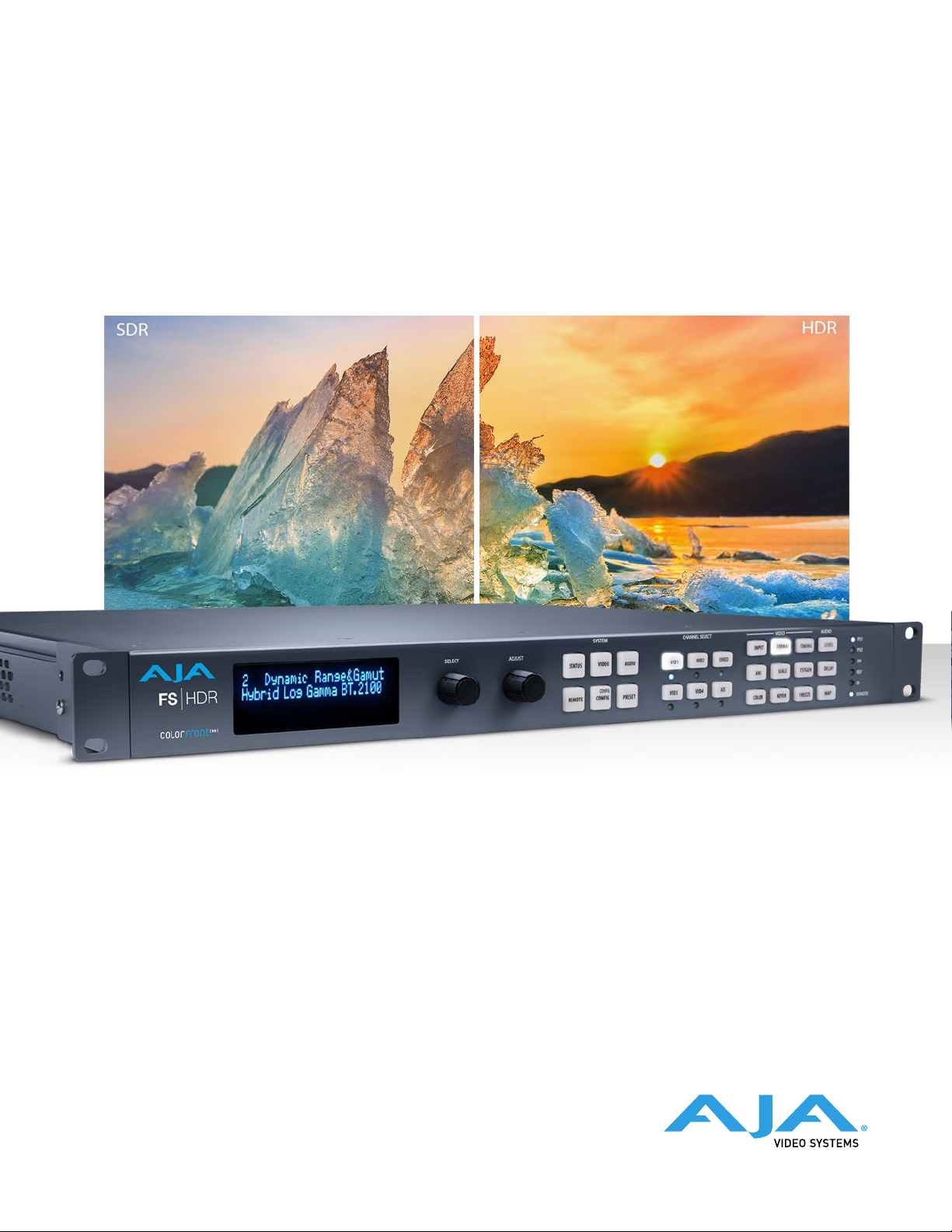
FS-HDR
Frame Synchronizer/Converter/HDR-WCG Processor
Installation and Operation Guide
Version 1.0r1
Published September 8, 2017
Page 2
Notices
Trademarks
AJA® and Because it matters.® are registered trademarks of AJA Video Systems, Inc.
for use with most AJA products. AJA™ is a trademark of AJA Video Systems, Inc. for
use with recorder, router, software and camera products. Because it matters.™ is a
trademark of AJA Video Systems, Inc. for use with camera products.
CION®, Corvid Ultra®, lo®, Ki Pro®, KONA®, KUMO®, ROI® and T-Tap® are registered
trademarks of AJA Video Systems, Inc.
AJA Control Room™, KiStor™, Science of the Beautiful™, TruScale™, TruZoom™,
V2Analog™ and V2Digital™ are trademarks of AJA Video Systems, Inc.
AirPort, Apple, Apple logo, AppleShare, AppleTalk, FireWire, iPod, iPod touch,
Mac, Macintosh and ProRes, are registered trademarks of Apple Inc. Final Cut Pro,
QuickTime and QuickTime logo are trademarks of Apple Inc.
Avid, Avid DNxHD and Media Composer are registered trademarks of Avid
Technology, Inc.
Adobe is a registered trademark of Adobe Systems Incorporated in the United States
and/or other countries.
HDMI, the HDMI logo and High-Definition Multimedia Interface are trademarks or
registered trademarks of HDMI Licensing, LLC.
DVI is a registered trademark of DDWG.
TASCAM is a registered trademark of TEAC Corporation.
Dolby and the double-D Dolby logo are registered trademarks of Dolby Laboratories
Licensing Corporation.
openGear® Ross, ROSS, ROSS®, and MLE are registered trademarks of Ross Video.
DashBoard Control System™ is a trademark of Ross Video.
All other trademarks are the property of their respective holders.
Copyright
Copyright © 2017 AJA Video Systems, Inc. All rights reserved. All information in
this manual is subject to change without notice. No part of the document may be
reproduced or transmitted in any form, or by any means, electronic or mechanical,
including photocopying or recording, without the express written permission of AJA
Video Systems, Inc.
Contacting AJA Support
When calling for support, have all information at hand prior to calling. To contact AJA
for sales or support, use any of the following methods:
Telephone +1.530.271.3190
FAX +1.530.271.3140
Web https://www.aja.com
Support Email [email protected]
Sales Email [email protected]
FS-HDR Frame Synchronizer/Converter/HDR-WCG Processor v1.0r1 2 www.aja.com
Page 3

Contents
Notices . . . . . . . . . . . . . . . . . . . . . . . . . . . . . . . . . . . . . .2
Trademarks . . . . . . . . . . . . . . . . . . . . . . . . . . . . . . . . . . . . . . . . . . . 2
Copyright . . . . . . . . . . . . . . . . . . . . . . . . . . . . . . . . . . . . . . . . . . . . 2
Contacting AJA Support . . . . . . . . . . . . . . . . . . . . . . . . . . . . . . . . . . . 2
Chapter 1 – Introduction . . . . . . . . . . . . . . . . . . . . . . . . . . . 8
Overview. . . . . . . . . . . . . . . . . . . . . . . . . . . . . . . . . . . . . . . . . . . . . 8
Video Features . . . . . . . . . . . . . . . . . . . . . . . . . . . . . . . . . . . . . . . 9
Audio Features . . . . . . . . . . . . . . . . . . . . . . . . . . . . . . . . . . . . . . . 9
Other Features. . . . . . . . . . . . . . . . . . . . . . . . . . . . . . . . . . . . . . . 10
FS-HDR Control. . . . . . . . . . . . . . . . . . . . . . . . . . . . . . . . . . . . . . . . 10
Front Panel Control. . . . . . . . . . . . . . . . . . . . . . . . . . . . . . . . . . . . 10
Remote Web Browser Control . . . . . . . . . . . . . . . . . . . . . . . . . . . . . 10
GPI Inputs and Outputs . . . . . . . . . . . . . . . . . . . . . . . . . . . . . . . . . 10
SNMP Interface Monitoring . . . . . . . . . . . . . . . . . . . . . . . . . . . . . . 10
Technical Description . . . . . . . . . . . . . . . . . . . . . . . . . . . . . . . . . . . . 11
Four Channel Mode . . . . . . . . . . . . . . . . . . . . . . . . . . . . . . . . . . . 11
Single Channel Mode . . . . . . . . . . . . . . . . . . . . . . . . . . . . . . . . . . 12
Video Processor(s) . . . . . . . . . . . . . . . . . . . . . . . . . . . . . . . . . . . . 13
Audio Processor. . . . . . . . . . . . . . . . . . . . . . . . . . . . . . . . . . . . . . 14
Optional FS-HDR Features . . . . . . . . . . . . . . . . . . . . . . . . . . . . . . . . . 14
SFP I/O . . . . . . . . . . . . . . . . . . . . . . . . . . . . . . . . . . . . . . . . . . . . 14
Operation Overview. . . . . . . . . . . . . . . . . . . . . . . . . . . . . . . . . . . . . 14
About Inputs and Outputs . . . . . . . . . . . . . . . . . . . . . . . . . . . . . . . 14
About Reference and Genlock Source. . . . . . . . . . . . . . . . . . . . . . . . 14
HDR and WCG Background. . . . . . . . . . . . . . . . . . . . . . . . . . . . . . . 15
Retained Settings. . . . . . . . . . . . . . . . . . . . . . . . . . . . . . . . . . . . . 15
In This Manual . . . . . . . . . . . . . . . . . . . . . . . . . . . . . . . . . . . . . . . . 16
Chapter 2 – Controls, Indicators, and Connections . . . . . . . . . . 17
Overview. . . . . . . . . . . . . . . . . . . . . . . . . . . . . . . . . . . . . . . . . . . . 17
Front Panel Description . . . . . . . . . . . . . . . . . . . . . . . . . . . . . . . . . . 17
Front Panel Layout and Operation . . . . . . . . . . . . . . . . . . . . . . . . . . 17
Operational Summary . . . . . . . . . . . . . . . . . . . . . . . . . . . . . . . . . . 18
Alphanumeric Display . . . . . . . . . . . . . . . . . . . . . . . . . . . . . . . . . . 19
Control Knobs . . . . . . . . . . . . . . . . . . . . . . . . . . . . . . . . . . . . . . . 19
Button Menus . . . . . . . . . . . . . . . . . . . . . . . . . . . . . . . . . . . . . . . 20
Status LED Indicators . . . . . . . . . . . . . . . . . . . . . . . . . . . . . . . . . . 23
Incompatibility Alarms . . . . . . . . . . . . . . . . . . . . . . . . . . . . . . . . . 23
Rear Panel Description . . . . . . . . . . . . . . . . . . . . . . . . . . . . . . . . . . . 24
Connectors. . . . . . . . . . . . . . . . . . . . . . . . . . . . . . . . . . . . . . . . . 24
Chapter 3 – Installation & Conguration . . . . . . . . . . . . . . . . 27
Installation Overview . . . . . . . . . . . . . . . . . . . . . . . . . . . . . . . . . . . . 27
Installation Summary . . . . . . . . . . . . . . . . . . . . . . . . . . . . . . . . . . 27
Unpacking . . . . . . . . . . . . . . . . . . . . . . . . . . . . . . . . . . . . . . . . . . . 28
Shipping Box Contents . . . . . . . . . . . . . . . . . . . . . . . . . . . . . . . . . 28
Installing Optional SFP I/O Modules. . . . . . . . . . . . . . . . . . . . . . . . . . . 28
FS-HDR Chassis Installation . . . . . . . . . . . . . . . . . . . . . . . . . . . . . . . . 28
Physical Requirements for Mounting the Chassis. . . . . . . . . . . . . . . . . 28
Power Requirements. . . . . . . . . . . . . . . . . . . . . . . . . . . . . . . . . . . 29
Networking . . . . . . . . . . . . . . . . . . . . . . . . . . . . . . . . . . . . . . . . . . 29
FS-HDR Default Network Settings . . . . . . . . . . . . . . . . . . . . . . . . . . 29
Networking Using DHCP or Default Static IP. . . . . . . . . . . . . . . . . . . . 29
Networking FS-HDRhe 30 Using Your Own Static IP . . . . . . . . . . . . . . . 30
Using Ping to Test the Network Connection . . . . . . . . . . . . . . . . . . . . 30
Web Browser Control . . . . . . . . . . . . . . . . . . . . . . . . . . . . . . . . . . . . 31
Software Update Installation . . . . . . . . . . . . . . . . . . . . . . . . . . . . . . . 32
FS-HDR Frame Synchronizer/Converter/HDR-WCG Processor v1.0r1 3 www.aja.com
Page 4

Download the Latest Software . . . . . . . . . . . . . . . . . . . . . . . . . . . . 32
Unpack the Software . . . . . . . . . . . . . . . . . . . . . . . . . . . . . . . . . . 32
Uploading and Installing the Software to the FS-HDR . . . . . . . . . . . . . 32
System Cabling. . . . . . . . . . . . . . . . . . . . . . . . . . . . . . . . . . . . . . . . 33
Four Channel Mode Conguration Examples . . . . . . . . . . . . . . . . . . . 33
Single Channel Mode Conguration Examples . . . . . . . . . . . . . . . . . . 36
Local Monitoring with the FS-HDR . . . . . . . . . . . . . . . . . . . . . . . . . . 39
GPI Connections . . . . . . . . . . . . . . . . . . . . . . . . . . . . . . . . . . . . . 40
Stand Alone Tests . . . . . . . . . . . . . . . . . . . . . . . . . . . . . . . . . . . . . . 40
First Power Up . . . . . . . . . . . . . . . . . . . . . . . . . . . . . . . . . . . . . . . 40
FS-HDR Processing Examples . . . . . . . . . . . . . . . . . . . . . . . . . . . . . . . 41
FS-HDRbout 41 Operating Modes . . . . . . . . . . . . . . . . . . . . . . . . . . 41
General FS-HDR Setup. . . . . . . . . . . . . . . . . . . . . . . . . . . . . . . . . . 42
HD Video Camera to UltraHD HDR Live Production . . . . . . . . . . . . . . . 43
4K HDR to HD HDR Down and Cross-Conversion . . . . . . . . . . . . . . . . . 44
Multiple Legacy Device SDR To HDR Live Conversion . . . . . . . . . . . . . . 46
Multiple Simultaneous HDR and SDR Distribution . . . . . . . . . . . . . . . . 48
Dual Stream Signal Separation . . . . . . . . . . . . . . . . . . . . . . . . . . . . 51
Chapter 4 – Display Menus . . . . . . . . . . . . . . . . . . . . . . . . . 53
Overview. . . . . . . . . . . . . . . . . . . . . . . . . . . . . . . . . . . . . . . . . . . . 53
FS-HDR Modes, System Parameters, and Video Parameters. . . . . . . . . . 53
Presets and FS-HDR Operating Mode . . . . . . . . . . . . . . . . . . . . . . . . 54
Parameter Menus. . . . . . . . . . . . . . . . . . . . . . . . . . . . . . . . . . . . . 54
STATUS Menu Group . . . . . . . . . . . . . . . . . . . . . . . . . . . . . . . . . . . . 54
System Status . . . . . . . . . . . . . . . . . . . . . . . . . . . . . . . . . . . . . . . 54
Vid 1/2 I/O . . . . . . . . . . . . . . . . . . . . . . . . . . . . . . . . . . . . . . . . . 55
Vid 3/4 I/O . . . . . . . . . . . . . . . . . . . . . . . . . . . . . . . . . . . . . . . . . 55
Vid I/O . . . . . . . . . . . . . . . . . . . . . . . . . . . . . . . . . . . . . . . . . . . . 55
Vid 1 Format . . . . . . . . . . . . . . . . . . . . . . . . . . . . . . . . . . . . . . . . 55
Vid 2-4 Format. . . . . . . . . . . . . . . . . . . . . . . . . . . . . . . . . . . . . . . 55
Vid 1 Alarm . . . . . . . . . . . . . . . . . . . . . . . . . . . . . . . . . . . . . . . . . 55
Vid 2-4 Alarm . . . . . . . . . . . . . . . . . . . . . . . . . . . . . . . . . . . . . . . 55
Vid Alarm . . . . . . . . . . . . . . . . . . . . . . . . . . . . . . . . . . . . . . . . . . 56
SDI Input . . . . . . . . . . . . . . . . . . . . . . . . . . . . . . . . . . . . . . . . . . 56
Monitor Output . . . . . . . . . . . . . . . . . . . . . . . . . . . . . . . . . . . . . . 56
AES Input . . . . . . . . . . . . . . . . . . . . . . . . . . . . . . . . . . . . . . . . . . 56
MADI In/Out . . . . . . . . . . . . . . . . . . . . . . . . . . . . . . . . . . . . . . . . 56
Power/Temp Alarm. . . . . . . . . . . . . . . . . . . . . . . . . . . . . . . . . . . . 56
Caption Status. . . . . . . . . . . . . . . . . . . . . . . . . . . . . . . . . . . . . . . 57
REMOTE Menu Group . . . . . . . . . . . . . . . . . . . . . . . . . . . . . . . . . . . . 57
1 Remote Control . . . . . . . . . . . . . . . . . . . . . . . . . . . . . . . . . . . . . 57
1.1 Authentication . . . . . . . . . . . . . . . . . . . . . . . . . . . . . . . . . . . . 57
2.1–4 GPI IN 1–4 Response . . . . . . . . . . . . . . . . . . . . . . . . . . . . . . . 58
Interaction of Presets and GPIs . . . . . . . . . . . . . . . . . . . . . . . . . . . . 59
3.1–4 GPI 1–4 OUT . . . . . . . . . . . . . . . . . . . . . . . . . . . . . . . . . . . . 59
VIDEO Menu Group . . . . . . . . . . . . . . . . . . . . . . . . . . . . . . . . . . . . . 59
1 Output Frame Rate. . . . . . . . . . . . . . . . . . . . . . . . . . . . . . . . . . . 60
2 Genlock Source . . . . . . . . . . . . . . . . . . . . . . . . . . . . . . . . . . . . . 60
3.1 Mon 2K Crop. . . . . . . . . . . . . . . . . . . . . . . . . . . . . . . . . . . . . . 60
3.2 HDMI RGB Range. . . . . . . . . . . . . . . . . . . . . . . . . . . . . . . . . . . 60
3.3 Monitor Map . . . . . . . . . . . . . . . . . . . . . . . . . . . . . . . . . . . . . 60
4.1 SDI1 3G Detect . . . . . . . . . . . . . . . . . . . . . . . . . . . . . . . . . . . . 61
4.2 SDI2 Input Protect . . . . . . . . . . . . . . . . . . . . . . . . . . . . . . . . . . 61
4.3, 4.5, 4.7 SDI3/5/7 3G Detect . . . . . . . . . . . . . . . . . . . . . . . . . . . . 61
4.4, 4.6, 4.8 SDI4/6/8 Input Protect . . . . . . . . . . . . . . . . . . . . . . . . . . 62
5.1 VidProc Bypass . . . . . . . . . . . . . . . . . . . . . . . . . . . . . . . . . . . . 62
CONFIG Menu Group . . . . . . . . . . . . . . . . . . . . . . . . . . . . . . . . . . . . 62
1 System Name . . . . . . . . . . . . . . . . . . . . . . . . . . . . . . . . . . . . . . 62
2 FS-HDR Mode . . . . . . . . . . . . . . . . . . . . . . . . . . . . . . . . . . . . . . 63
3.1 IP Cong . . . . . . . . . . . . . . . . . . . . . . . . . . . . . . . . . . . . . . . . 63
FS-HDR Frame Synchronizer/Converter/HDR-WCG Processor v1.0r1 4 www.aja.com
Page 5

3.2 IP Address . . . . . . . . . . . . . . . . . . . . . . . . . . . . . . . . . . . . . . . 63
3.3 Subnet Mask. . . . . . . . . . . . . . . . . . . . . . . . . . . . . . . . . . . . . . 64
3.4 Default Gateway . . . . . . . . . . . . . . . . . . . . . . . . . . . . . . . . . . . 64
3.5 MAC Address (view only) . . . . . . . . . . . . . . . . . . . . . . . . . . . . . . 64
4 SNMP Enable Parameters. . . . . . . . . . . . . . . . . . . . . . . . . . . . . . . 64
About FS-HDR Alarms . . . . . . . . . . . . . . . . . . . . . . . . . . . . . . . . . . 64
5.1, 5.2 Power Supply 1-2 Alarm . . . . . . . . . . . . . . . . . . . . . . . . . . . . 65
6 Vid Format Alarm. . . . . . . . . . . . . . . . . . . . . . . . . . . . . . . . . . . . 65
6.1-6.4 Vid1-4 Format Alarm . . . . . . . . . . . . . . . . . . . . . . . . . . . . . . 65
7 Reference Alarm . . . . . . . . . . . . . . . . . . . . . . . . . . . . . . . . . . . . 65
8 Hidden Menus. . . . . . . . . . . . . . . . . . . . . . . . . . . . . . . . . . . . . . 65
9 Screen Saver . . . . . . . . . . . . . . . . . . . . . . . . . . . . . . . . . . . . . . . 65
10 Display Intensity. . . . . . . . . . . . . . . . . . . . . . . . . . . . . . . . . . . . 66
11 Fan Speed. . . . . . . . . . . . . . . . . . . . . . . . . . . . . . . . . . . . . . . . 66
12 Serial Number . . . . . . . . . . . . . . . . . . . . . . . . . . . . . . . . . . . . . 66
13 Software Version . . . . . . . . . . . . . . . . . . . . . . . . . . . . . . . . . . . 66
14 Reboot. . . . . . . . . . . . . . . . . . . . . . . . . . . . . . . . . . . . . . . . . . 66
AUDIO Menu Group . . . . . . . . . . . . . . . . . . . . . . . . . . . . . . . . . . . . . 66
1 MADI Output Mode . . . . . . . . . . . . . . . . . . . . . . . . . . . . . . . . . . 66
2.1-2.8 SDI 1-8 SRC Mode . . . . . . . . . . . . . . . . . . . . . . . . . . . . . . . . 67
2.9 AES SRC Mode . . . . . . . . . . . . . . . . . . . . . . . . . . . . . . . . . . . . 67
2.10 MADI BNC SRC Mode . . . . . . . . . . . . . . . . . . . . . . . . . . . . . . . 67
2.11 MADI Fiber SRC Mode . . . . . . . . . . . . . . . . . . . . . . . . . . . . . . . 67
3.0 Mix Down 1 Mode . . . . . . . . . . . . . . . . . . . . . . . . . . . . . . . . . . 68
3.0 Mix Down 2 Mode . . . . . . . . . . . . . . . . . . . . . . . . . . . . . . . . . . 69
7 Mix Down Reset. . . . . . . . . . . . . . . . . . . . . . . . . . . . . . . . . . . . . 70
8 Global Audio Output . . . . . . . . . . . . . . . . . . . . . . . . . . . . . . . . . 70
9 Reset Mapped Output . . . . . . . . . . . . . . . . . . . . . . . . . . . . . . . . 70
PRESET Menu Group . . . . . . . . . . . . . . . . . . . . . . . . . . . . . . . . . . . . 70
1 Factory Preset . . . . . . . . . . . . . . . . . . . . . . . . . . . . . . . . . . . . . . 71
1.1-1.40 Presets #1-#40 . . . . . . . . . . . . . . . . . . . . . . . . . . . . . . . . . . 71
Video with Audio Routing . . . . . . . . . . . . . . . . . . . . . . . . . . . . . . . 71
Interaction of Presets and GPIs . . . . . . . . . . . . . . . . . . . . . . . . . . . . 71
Video Select Buttons VID1-VID4 . . . . . . . . . . . . . . . . . . . . . . . . . . . . . 72
INPUT Menu Group . . . . . . . . . . . . . . . . . . . . . . . . . . . . . . . . . . . . . 72
1 Input. . . . . . . . . . . . . . . . . . . . . . . . . . . . . . . . . . . . . . . . . . . . 72
2.1 Dynamic Range&Gamut . . . . . . . . . . . . . . . . . . . . . . . . . . . . . . 73
2.2 SDR Highlights . . . . . . . . . . . . . . . . . . . . . . . . . . . . . . . . . . . . 73
3 Loss of Input . . . . . . . . . . . . . . . . . . . . . . . . . . . . . . . . . . . . . . . 73
4 Reverse Telecine . . . . . . . . . . . . . . . . . . . . . . . . . . . . . . . . . . . . 73
5 Input Scan Format . . . . . . . . . . . . . . . . . . . . . . . . . . . . . . . . . . . 74
ANC Menu Group . . . . . . . . . . . . . . . . . . . . . . . . . . . . . . . . . . . . . . 75
1.1 AFD Out . . . . . . . . . . . . . . . . . . . . . . . . . . . . . . . . . . . . . . . . . 75
1.2 AFD VANC Output Lines . . . . . . . . . . . . . . . . . . . . . . . . . . . . . . 75
1.3 Downconvert AFD dt . . . . . . . . . . . . . . . . . . . . . . . . . . . . . . . 76
2 Caption Xlator . . . . . . . . . . . . . . . . . . . . . . . . . . . . . . . . . . . . . . 76
3 SD Line 21 Blanking . . . . . . . . . . . . . . . . . . . . . . . . . . . . . . . . . . 76
COLOR Menu Group. . . . . . . . . . . . . . . . . . . . . . . . . . . . . . . . . . . . . 77
1.0 Proc Amp Enable (YUV) . . . . . . . . . . . . . . . . . . . . . . . . . . . . . . 77
3.0 Video Legalizer . . . . . . . . . . . . . . . . . . . . . . . . . . . . . . . . . . . . 77
FORMAT Menu Group. . . . . . . . . . . . . . . . . . . . . . . . . . . . . . . . . . . . 79
1 Output Format . . . . . . . . . . . . . . . . . . . . . . . . . . . . . . . . . . . . . 79
2.1 Dynamic Range&Gamut . . . . . . . . . . . . . . . . . . . . . . . . . . . . . . 79
2.2 Dynamic Range Clamp . . . . . . . . . . . . . . . . . . . . . . . . . . . . . . . 79
3.0 Link Cong SDI1, 2, 3, 4 . . . . . . . . . . . . . . . . . . . . . . . . . . . . . . . 80
3.1 Level B SDI1, 2, 3, 4 . . . . . . . . . . . . . . . . . . . . . . . . . . . . . . . . . . 80
3.0 Link Cong SDI1-4 . . . . . . . . . . . . . . . . . . . . . . . . . . . . . . . . . . 81
4.0 Link Cong SDI5-8 . . . . . . . . . . . . . . . . . . . . . . . . . . . . . . . . . . 81
5 Output Image Mapping. . . . . . . . . . . . . . . . . . . . . . . . . . . . . . . . 81
6 SD Aspect Ratio. . . . . . . . . . . . . . . . . . . . . . . . . . . . . . . . . . . . . 81
7 Upconvert Mode . . . . . . . . . . . . . . . . . . . . . . . . . . . . . . . . . . . . 82
FS-HDR Frame Synchronizer/Converter/HDR-WCG Processor v1.0r1 5 www.aja.com
Page 6

8 Downconvert Mode . . . . . . . . . . . . . . . . . . . . . . . . . . . . . . . . . . 83
SCALE Menu Group . . . . . . . . . . . . . . . . . . . . . . . . . . . . . . . . . . . . . 84
Custom Conversion Settings. . . . . . . . . . . . . . . . . . . . . . . . . . . . . . 84
1.0 Custom Size/Pos . . . . . . . . . . . . . . . . . . . . . . . . . . . . . . . . . . . 85
Region of Interest (ROI) . . . . . . . . . . . . . . . . . . . . . . . . . . . . . . . . . 86
KEYER Menu Group . . . . . . . . . . . . . . . . . . . . . . . . . . . . . . . . . . . . . 87
1 Background Fill . . . . . . . . . . . . . . . . . . . . . . . . . . . . . . . . . . . . . 87
2 Sidebar Edge . . . . . . . . . . . . . . . . . . . . . . . . . . . . . . . . . . . . . . 87
3.1 Matte Luma . . . . . . . . . . . . . . . . . . . . . . . . . . . . . . . . . . . . . . 88
3.2 Matte Chroma. . . . . . . . . . . . . . . . . . . . . . . . . . . . . . . . . . . . . 88
3.3 Matte Hue . . . . . . . . . . . . . . . . . . . . . . . . . . . . . . . . . . . . . . . 88
TIMING Menu Group . . . . . . . . . . . . . . . . . . . . . . . . . . . . . . . . . . . . 88
1 Output Timing H . . . . . . . . . . . . . . . . . . . . . . . . . . . . . . . . . . . . 88
2 Output Timing V . . . . . . . . . . . . . . . . . . . . . . . . . . . . . . . . . . . . 89
3 Frame Delay . . . . . . . . . . . . . . . . . . . . . . . . . . . . . . . . . . . . . . . 90
TSTGEN Menu Group . . . . . . . . . . . . . . . . . . . . . . . . . . . . . . . . . . . . 90
1 Test Pattern Gen . . . . . . . . . . . . . . . . . . . . . . . . . . . . . . . . . . . . 90
2 Test Pattern . . . . . . . . . . . . . . . . . . . . . . . . . . . . . . . . . . . . . . . 90
FREEZE Menu Group . . . . . . . . . . . . . . . . . . . . . . . . . . . . . . . . . . . . 90
1 Freeze Output . . . . . . . . . . . . . . . . . . . . . . . . . . . . . . . . . . . . . 91
Audio Select Buttons EMBED, AES . . . . . . . . . . . . . . . . . . . . . . . . . . . . 91
LEVEL Menu Group . . . . . . . . . . . . . . . . . . . . . . . . . . . . . . . . . . . . . 91
EMBED Level Menus . . . . . . . . . . . . . . . . . . . . . . . . . . . . . . . . . . . 91
AES/MADI Menus . . . . . . . . . . . . . . . . . . . . . . . . . . . . . . . . . . . . . 93
DELAY Menu Group . . . . . . . . . . . . . . . . . . . . . . . . . . . . . . . . . . . . . 93
EMBED Delay Menus . . . . . . . . . . . . . . . . . . . . . . . . . . . . . . . . . . . 93
AES/MADI Delay Menus . . . . . . . . . . . . . . . . . . . . . . . . . . . . . . . . . 94
MAP Menu Group . . . . . . . . . . . . . . . . . . . . . . . . . . . . . . . . . . . . . . 95
About Audio Routing . . . . . . . . . . . . . . . . . . . . . . . . . . . . . . . . . . 95
1.0 Vid 1 Audio Out. . . . . . . . . . . . . . . . . . . . . . . . . . . . . . . . . . . . 95
2.0-4.0 SDI2-4 Audio Out . . . . . . . . . . . . . . . . . . . . . . . . . . . . . . . . 96
Chapter 5 – Browser Remote Control . . . . . . . . . . . . . . . . . . 97
Remote FS-HDR Control Via a Web Browser. . . . . . . . . . . . . . . . . . . . . . 97
General Web Browser Screen Description . . . . . . . . . . . . . . . . . . . . . 97
ControlliFS-HDRg Multiple 99s . . . . . . . . . . . . . . . . . . . . . . . . . . . . 99
Resetting Values To Factory Default Settings . . . . . . . . . . . . . . . . . . . 99
Drop Down Parameter Operation . . . . . . . . . . . . . . . . . . . . . . . . . . 99
Slider Operation . . . . . . . . . . . . . . . . . . . . . . . . . . . . . . . . . . . . . 99
Sub-Menus . . . . . . . . . . . . . . . . . . . . . . . . . . . . . . . . . . . . . . . . 100
Screen Descriptions . . . . . . . . . . . . . . . . . . . . . . . . . . . . . . . . . . . . 100
Network Pane and Network Conguration Screen . . . . . . . . . . . . . . . . 100
IP Address Type . . . . . . . . . . . . . . . . . . . . . . . . . . . . . . . . . . . . . .101
IP Address . . . . . . . . . . . . . . . . . . . . . . . . . . . . . . . . . . . . . . . . .101
Netmask. . . . . . . . . . . . . . . . . . . . . . . . . . . . . . . . . . . . . . . . . . .101
Default Gateway . . . . . . . . . . . . . . . . . . . . . . . . . . . . . . . . . . . . .101
Alarm Conguration Screen. . . . . . . . . . . . . . . . . . . . . . . . . . . . . . . 102
Status Screen . . . . . . . . . . . . . . . . . . . . . . . . . . . . . . . . . . . . . . . . 103
Cong Screen . . . . . . . . . . . . . . . . . . . . . . . . . . . . . . . . . . . . . . . . 105
System Name . . . . . . . . . . . . . . . . . . . . . . . . . . . . . . . . . . . . . . 105
FS-HDR Mode . . . . . . . . . . . . . . . . . . . . . . . . . . . . . . . . . . . . . . 105
SNMP Parameters. . . . . . . . . . . . . . . . . . . . . . . . . . . . . . . . . . . . 105
Hidden Menus. . . . . . . . . . . . . . . . . . . . . . . . . . . . . . . . . . . . . . 106
Screen Saver . . . . . . . . . . . . . . . . . . . . . . . . . . . . . . . . . . . . . . . 106
Display Intensity . . . . . . . . . . . . . . . . . . . . . . . . . . . . . . . . . . . . 106
Fan Speed . . . . . . . . . . . . . . . . . . . . . . . . . . . . . . . . . . . . . . . . 106
UPnP Host . . . . . . . . . . . . . . . . . . . . . . . . . . . . . . . . . . . . . . . . 106
UPnP Proxy . . . . . . . . . . . . . . . . . . . . . . . . . . . . . . . . . . . . . . . . 106
Video Screen . . . . . . . . . . . . . . . . . . . . . . . . . . . . . . . . . . . . . . . . .107
Audio Screen . . . . . . . . . . . . . . . . . . . . . . . . . . . . . . . . . . . . . . . . 108
Presets Screen . . . . . . . . . . . . . . . . . . . . . . . . . . . . . . . . . . . . . . . 109
FS-HDR Frame Synchronizer/Converter/HDR-WCG Processor v1.0r1 6 www.aja.com
Page 7

Presets Screen Controls . . . . . . . . . . . . . . . . . . . . . . . . . . . . . . . . 109
Interaction of Presets and GPIs . . . . . . . . . . . . . . . . . . . . . . . . . . . .110
Remote Screen . . . . . . . . . . . . . . . . . . . . . . . . . . . . . . . . . . . . . . . . 111
Firmware Screen . . . . . . . . . . . . . . . . . . . . . . . . . . . . . . . . . . . . . . .111
Video Channel Screens . . . . . . . . . . . . . . . . . . . . . . . . . . . . . . . . . . .112
Input Screen . . . . . . . . . . . . . . . . . . . . . . . . . . . . . . . . . . . . . . . .112
Format Screen . . . . . . . . . . . . . . . . . . . . . . . . . . . . . . . . . . . . . . .113
Timing Screen . . . . . . . . . . . . . . . . . . . . . . . . . . . . . . . . . . . . . . .113
Scale Screen . . . . . . . . . . . . . . . . . . . . . . . . . . . . . . . . . . . . . . . .114
Keyer Screen . . . . . . . . . . . . . . . . . . . . . . . . . . . . . . . . . . . . . . . .114
Test Gen Screen . . . . . . . . . . . . . . . . . . . . . . . . . . . . . . . . . . . . . .115
Color Screen . . . . . . . . . . . . . . . . . . . . . . . . . . . . . . . . . . . . . . . .115
ANC Screen. . . . . . . . . . . . . . . . . . . . . . . . . . . . . . . . . . . . . . . . .115
Freeze Screen . . . . . . . . . . . . . . . . . . . . . . . . . . . . . . . . . . . . . . .116
Embedded Audio Channel Screens . . . . . . . . . . . . . . . . . . . . . . . . . . . 116
Embed Level Screen . . . . . . . . . . . . . . . . . . . . . . . . . . . . . . . . . . .116
Embed Delay Screen . . . . . . . . . . . . . . . . . . . . . . . . . . . . . . . . . . .117
Embed Map Screen. . . . . . . . . . . . . . . . . . . . . . . . . . . . . . . . . . . .117
AES (and MADI) Audio Channel Screens . . . . . . . . . . . . . . . . . . . . . . . .117
AES/MADI Level Screen . . . . . . . . . . . . . . . . . . . . . . . . . . . . . . . . .118
AES/MADI Delay Screen. . . . . . . . . . . . . . . . . . . . . . . . . . . . . . . . .118
AES/MADI Map Screen . . . . . . . . . . . . . . . . . . . . . . . . . . . . . . . . .119
Chapter 6 – SNMP. . . . . . . . . . . . . . . . . . . . . . . . . . . . . . 120
FS-HDR Simple Network Management Protocol. . . . . . . . . . . . . . . . . . .120
SNMP Conguration . . . . . . . . . . . . . . . . . . . . . . . . . . . . . . . . . . . .120
AJA MIBs . . . . . . . . . . . . . . . . . . . . . . . . . . . . . . . . . . . . . . . . . .120
Front Panel SNMP Conguration . . . . . . . . . . . . . . . . . . . . . . . . . . .121
Web Browser SNMP Conguration. . . . . . . . . . . . . . . . . . . . . . . . . .121
SNMP Conguration Parameters. . . . . . . . . . . . . . . . . . . . . . . . . . . . .12 2
4.0 SNMP Enable . . . . . . . . . . . . . . . . . . . . . . . . . . . . . . . . . . . . .122
4.1 SNMP Trap Destination 1 . . . . . . . . . . . . . . . . . . . . . . . . . . . . . .122
4.2 SNMP Trap Port1. . . . . . . . . . . . . . . . . . . . . . . . . . . . . . . . . . .122
4.3 SNMP Trap Destination 2. . . . . . . . . . . . . . . . . . . . . . . . . . . . . .122
4.4 SNMP Trap Port2. . . . . . . . . . . . . . . . . . . . . . . . . . . . . . . . . . .122
Appendix A – Specications . . . . . . . . . . . . . . . . . . . . . . . 123
FS-HDR Tech Specs . . . . . . . . . . . . . . . . . . . . . . . . . . . . . . . . . . . . .123
Appendix B – FS-HDR Pinouts . . . . . . . . . . . . . . . . . . . . . . 128
GPI Pinouts . . . . . . . . . . . . . . . . . . . . . . . . . . . . . . . . . . . . . . . . . .128
Audio Connection Pinouts. . . . . . . . . . . . . . . . . . . . . . . . . . . . . . . . .129
Digital Audio. . . . . . . . . . . . . . . . . . . . . . . . . . . . . . . . . . . . . . . .12 9
Appendix C – Safety & Compliance. . . . . . . . . . . . . . . . . . . 130
Warranty Information . . . . . . . . . . . . . . . . . . . . . . . . . . . 139
Limited Warranty. . . . . . . . . . . . . . . . . . . . . . . . . . . . . . . . . . . . . . .139
Index. . . . . . . . . . . . . . . . . . . . . . . . . . . . . . . . . . . . . . 140
FS-HDR Frame Synchronizer/Converter/HDR-WCG Processor v1.0r1 7 www.aja.com
Page 8
Chapter 1 – Introduction
Overview
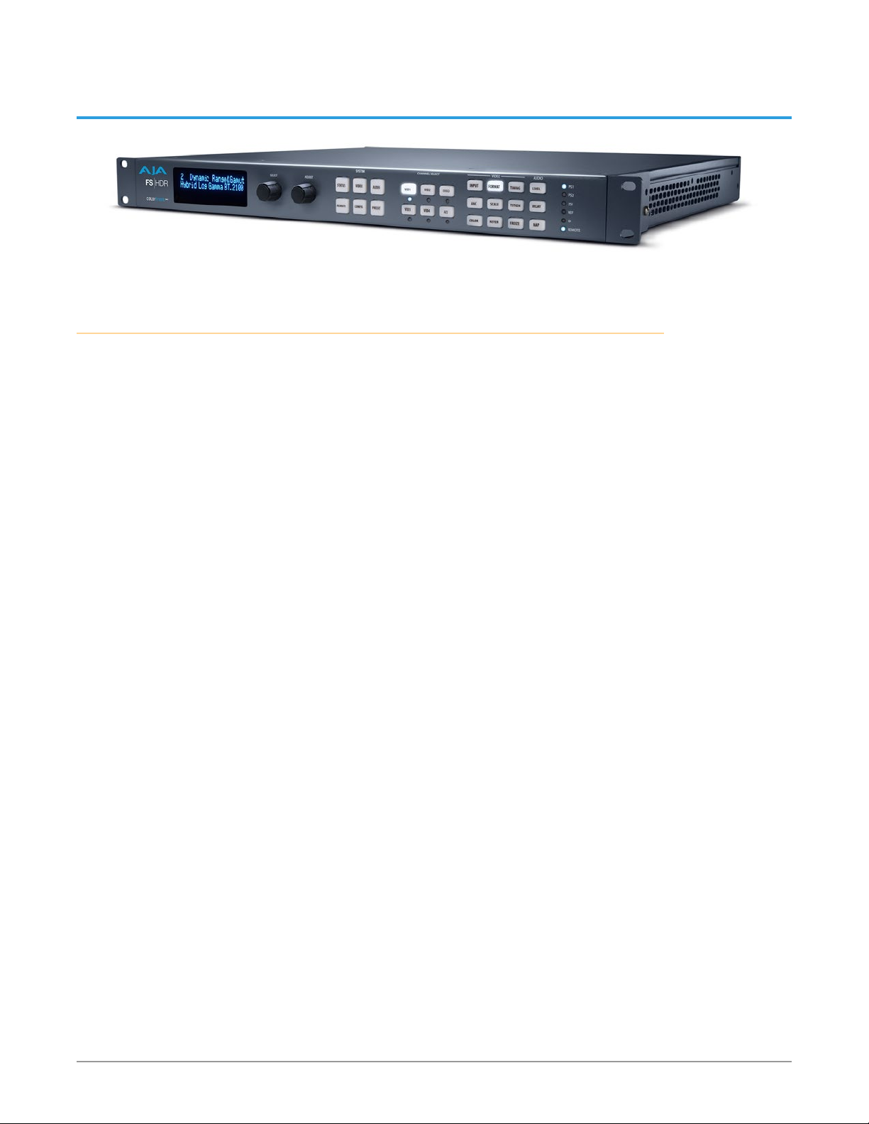
FS-HDR, a 1RU, rack-mount, universal converter/frame synchronizer, is designed
specifically to meet the HDR (High Dynamic Range) and WCG (Wide Color Gamut)
needs of broadcast, OTT, post and live event AV environments, where real time,
low-latency processing and color fidelity is required for 4K/UltraHD and 2K/HD
workflows. Developed in partnership with Colorfront, the FS-HDR’s HDR/WCG
functionality is powered by Colorfront Engine™ proprietary video processing
algorithms. FS-HDR also serves as a full, 1-channel up, down, cross-converter for
4K/UltraHD/2K/HD conversion and frame sync needs and in 4-Channel mode,
offers 4 independent channels of 2K/HD conversion.
The pursuit of High Dynamic Range (HDR) is the dream of getting closer to the
Human Visual System (HVS) in all that we experience as viewers. FS-HDR has been
designed to get us all there faster with a low profile, stand alone and real time
device uniquely designed to bridge SDR to HDR, HDR to SDR and HDR to HDR, all
in real time.
HDR Conversions:
• HDR to HDR
• HDR to SDR
• SDR to HDR
WCG Conversions:
• BT.709 and BT.2020
Up and Down Conversions:
• Converting HD SDR BT.709 sources to UHD HDR BT.2020
• Converting UHD HDR BT.2020 sources to HD SDR BT.709
FS-HDR’s extensive digital video connectivity is only matched by its expansive
digital audio flexibility. The growth of 5.1 and 7.1 audio has increased the number
of audio channels that must be managed in a production as well as needing to
create stereo mixdowns from 5.1 and 7.1 sources. The MADI standard provides
a convenient way to transport large numbers of audio channels along a single
cable, simplifying the cabling demands for broadcasters, mobile trucks and
production. FS-HDR supports both fiber and coax connections with 128-channel
MADI input and output. An internal 277x208 audio matrix allows full routing of
MADI, mixdowns and all audio coming from SDI, fiber and AES sources for an
incredible amount of audio processing capability in a single box.
FS-HDR Frame Synchronizer/Converter/HDR-WCG Processor v1.0r1 8 www.aja.com
Page 9

Video Features
• Integrated Colorfront Engine video processing
• Video Dynamic Range & Gamut supported inputs:
• SDR BT.709 100 Nits (default)
• PQ BT.2020 1000 Nits
• PQ P3D65 1000 Nits
• Hybrid Log Gamma BT.2100
• Sony S-Gamut3/S-Log3
• Arri Log C Wide Gamut
• Panasonic V-Log
• Red Log3G10 Wide Gamut
• Canon Log 2
• Canon Log 3
• Video Dynamic Range & Gamut supported outputs:
• SDR BT.709 100 Nits (default)
• PQ BT.2020 1000 Nits
• Hybrid Log Gamma BT.2100
• Sony S-Gamut3/S-Log3
• Support for two modes: Four-channel 2K/HD/SD or Single-channel 4K/
UltraHD/2K/HD/SD workow support
• 4K/UltraHD/2K/HD/SD video processing and up, down, cross-conversion;
easily frame sync any camera feed for UltraHD production
• Full range of I/O options for 4K/UltraHD include Dual 3Gb, Quad 3Gb, 6Gb,
12Gb over a range of SDI and optional SFP choices
• Single-link, dual-link, quad link conversion
• Automatic link timing alignment for dual and quad link SDI inputs
• Frame Synchronization
• Genlock to external loop through reference or SDI input
• YCbCr, 4:2:2, 10-bit
• BNC and HDMI monitoring output (single channel, 2K/HD/SD non HDR format)
• Frame Rate Conversion (3:2, 1:2, 2:1, but not for 4K/UHD converted to 4K/UHD)
• Quadrant and Two Sample Interleave (2SI) mapping conversion
• De-interlacing and Interlacing
• Video Proc Amp controls
• 3:2 cadence detection and removal for interlaced inputs and 3:2 cadence
generation on interlaced outputs
• Built in Test Pattern Generators
• Crop/Fill controls
• Matte generators for background ll
• Closed caption conversion (CEA-608/CEA-708)
• Adjustable output timing and delay
Audio Features
• 48kHz, 24 bit audio (20 bit for SD)
• Balanced AES I/O (16 ch input, 16 ch output)
• MADI I/O (128 ch input, 128 ch output, via BNC and Fiber)
• Embedded Audio (4x16 ch I/O in Four Channel Mode)
• 277x208 routable mono audio matrix
• Audio Sample Rate Conversion available on all audio inputs
• Independent level, phase, delay controls for each audio channel
FS-HDR Frame Synchronizer/Converter/HDR-WCG Processor v1.0r1 9 www.aja.com
Page 10

• 5.1 and 7.1 to Stereo mixdown processors
Other Features
• Simple operation, redesigned menu structure and quick access to features via
front panel buttons or web UI
• Built in web server. Supports remote status and control and remote software
updates
• Presets
• Redundant power
• Congurable Alarms
• EIA 19” Rack mountable 1RU frame, oering space, power and cost eciencies
ideal for outdoor broadcast trucks, post production or broadcast settings
• Five-year international warranty with unlimited technical support.
FS-HDR Control
FS-HDR operation can be monitored and changed in a number of ways. Feature
sets in each of the control methods vary, although the front panel and web
browser interfaces offer many of the same features.
Front Panel Control
The FS-HDR front panel offers the most direct control, ideal for use in machine
rooms or wherever quick changes and status checks must be made. The buttons
and knobs control menus in the display, allowing you to fully configure the
system according to your purposes. You can control inputs, outputs, processing
paths, keying, and much more.
Remote Web Browser Control
The FS-HDR internally contains an optimized web server that allows remote
monitoring and parameter setting via an Ethernet 10/100/1000 network-attached
computer running a web-browser. Networks can be closed local area networks,
a straight computer-to-FS-HDR cable, or for greatest flexibility, exposed through
a firewall to a broadband WAN. From a network-connected computer you can
communicate with one or more FS-HDR devices, and you can identify the one you
are connected to via LEDs on the FS-HDR’s front and rear panels.
GPI Inputs and Outputs
General Purpose Inputs and Outputs are available on the FS-HDR back panel to
provide contact closure control. Using the inputs, an external contact closure
activates a specified function on the FS-HDR. Using the outputs, specific FS-HDR
functions can produce a contact closure to activate any desired function on
external equipment. The functions to be activated by an input or that can activate
an output are set using the front panel and browser menus.
SNMP Interface Monitoring
SNMP offers remote network monitoring of alarm conditions.
FS-HDR Frame Synchronizer/Converter/HDR-WCG Processor v1.0r1 10 www.aja.com
Page 11

Technical Description
The FS-HDR features an incredibly flexible architecture, offering powerful Video
Processors for video conversion and processing, a separate Audio Processor, and
input and output video and audio signal routing. The FS-HDR has two completely
separate operating modes, selected with a menu parameter and then rebooting
the unit.
Four Channel Mode
In Four Channel Mode four independent HD/SD Video Processors are available,
Frame synchronization, genlock, and up, down and cross conversion is available
for a variety of video inputs and outputs. This mode also allows each Video
Processor to use any one of the other Video Processor’s video as a background or
sidebar key.
Each Video Processor routes its output to dedicated SDI output ports, depending
on the transport configuration. For single link transport the output of Video
Processor 1 is sent to SDI Out 1 and SDI Out 5 (for use with an optional SFP
module). For dual link transport, the output of Video Processor 1 is routed to
the SDI Out 1 and SDI Out 2 pair, and also to the SDI Out 5 and SDI Out 6 pair.
In addition, any Video Processor output can be routed to the monitor BNC and
HDMI outputs.
Four Channel Mode supports frame rate conversion within the same “family” of
frame rates. These families are:
• 59.94/29.97/23.98
• 50/25
• 60/30/24
Audio processing is available for all input audio, and audio can be routed to any of
the Video Processors for embedding, and to any of the audio output connectors.
FS-HDR Frame Synchronizer/Converter/HDR-WCG Processor v1.0r1 11 www.aja.com
Page 12
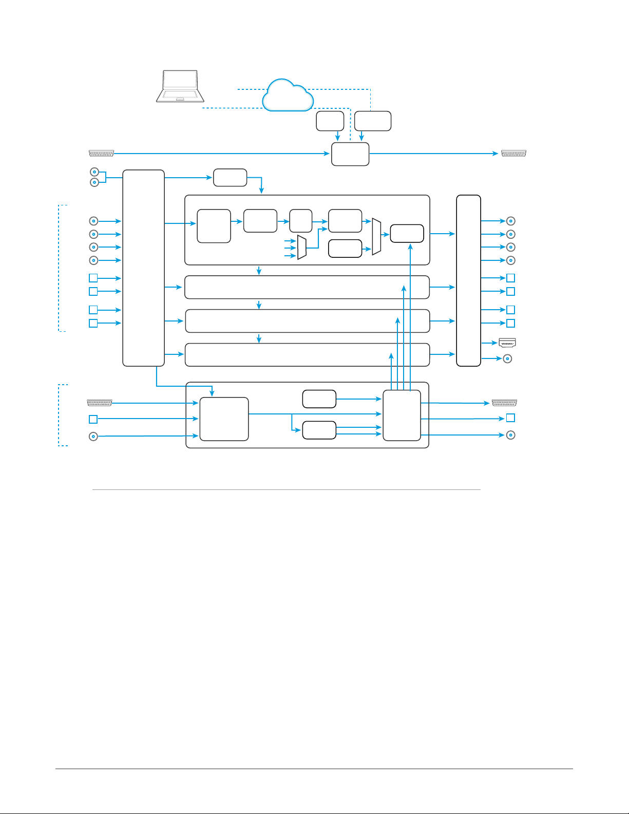
Figure 1. FS-HDR Simplified Block Diagram, Four Channel Mode
HD/SD
4 Channel
Mode
Inputs
GPI Inputs
(4)
Passive
Reference
Loop
Video with
Embedded Audio
SDI In 1
SDI In 2
SDI In 3
SDI In 4
Optional
SFP In 6
Optional
SFP In 5
Optional
SFP In 8
Optional
SFP In 7
Audio
AES/EBU
Digital
Audio In
MADI
Fiber In
MADI
BNC In
Video
Input
Crosspoint
Matrix
and
Audio
De-Embedders
SNMP Control
via Command Line
Video
128 ch.
Audio
16 ch.
Audio
64 ch.
Audio
64 ch.
Audio
Remote Web
Browser
Control
Genlock
HD/SD VIDEO PROCESSOR 1
Video
Converter
and
Frame Sync
HD/SD VIDEO PROCESSOR 2
(same as VP 1)
HD/SD VIDEO PROCESSOR 3
(same as VP 1)
HD/SD VIDEO PROCESSOR 4
(same as VP 1)
Audio Level,
Phase, Delay
Adjustment
Colorfront
Engine
Other Video Proc
AUDIO PROCESSOR
LAN or WAN
Ethernet
Black
Matte
L C R
(Ls Rs)
Lr Rr
Video
Proc
Amp
Panel
Control
Tone
Generator
Mix Down
(2)
FS-HDR CPU
Video
Sidebar
Keyer
Test Signal
Generator
4 x 16 ch. Audio
L
R
Embedded
Web Server
Audio
Embedder
Audio
Router and
Mapper
Video
Video
Output
Drivers
16 ch.
Audio
64 ch.
Audio
64 ch.
Audio
OutputsProcessing
GPI Outputs
(4)
SDI Out 1
SDI Out 2
SDI Out 3
SDI Out 4
Optional
SFP Out 5
Optional
SFP Out 6
Optional
SFP Out 7
Optional
SFP Out 8
Video Monitor
HDMI Out
Video Monitor
SDI Out
AES/EBU
Digital
Audio Out
MADI
Fiber Out
MADI
BNC Out
Single Channel Mode
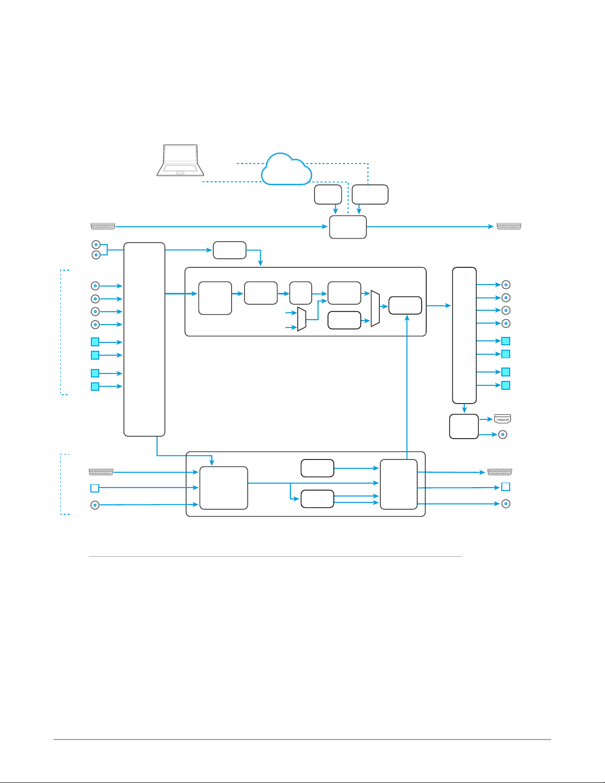
In Single Channel Mode a single 4K/UHD capable Video Processor is available,
allowing up, down, and cross conversion between a variety of 4K, UltraHD, 3G,
HD, and SD video formats.
The same processed output signal is sent to all the FS-HDR output connectors,
depending on transport configuration. For example, when in Quad Link mode,
the same signal is routed to the SDI Out 1-4 connectors, and also to the SDI Out
5-8 connectors (for use with optional SFP modules). In Dual Link mode four copies
of the processed video are routed to the SDI Out 1&2 pair, SDI Out 3&4, SDI
Out 5&6 and SDI Out 7&8. The Video Processor output is also available on the
monitor BNC and HDMI ports, and will be downconverted if necessary.
In Single Channel Mode only matte and black sidebar keying is available. Scale,
Position, Crop, and ROI are also available in Single Channel Mode for all formats
except when both the input and output formats are 4K/UltraHD.
Single Channel Mode frame rate conversion within the same “family” of frame
rates are supported for HD/SD signals, and for up and down format conversion
only to or from 4K/UltraHD signals. These frame rate families are:
• 59.94/29.97/23.98
• 50/25
• 60/30/24
FS-HDR Frame Synchronizer/Converter/HDR-WCG Processor v1.0r1 12 www.aja.com
Page 13
However, when the FS-HDR’s input and output are both 4K or UltraHD, the frame
rates must be the same even within the same family. For example, if the FS-HDR
receives UltraHD 59.94, when it is configured for UltraHD output, that frame rate
must also be 59.94.
Audio processing and routing in Single Channel Mode is similar to Four Channel
Mode.
Figure 2. FS-HDR Simplified Block Diagram, Single Channel Mode
4K/UltraHD
Single Channel
Mode
Inputs
GPI Inputs
(4)
Passive
Reference
Loop
Video with
Embedded Audio
SDI In 1
SDI In 2
SDI In 3
SDI In 4
*Optional
SFP In 6
*Optional
SFP In 5
*Optional
SFP In 8
*Optional
SFP In 7
*12/6G-SDI Capable Input
Audio
AES/EBU
Digital
Audio In
MADI
Fiber In
MADI
BNC In
Video
Input
Crosspoint
Matrix
and
Audio
De-Embedders
Remote Web
Browser
Control
SNMP Control
via Command Line
Genlock
4K/UltraHD VIDEO PROCESSOR
Video
Video Video
128 ch.
Audio
16 ch.
Audio
64 ch.
Audio
64 ch.
Audio
Converter
and
Frame Sync
Audio Level,
Phase, Delay
Adjustment
LAN or WAN
Ethernet
Colorfront
Engine
Black
Matte
AUDIO PROCESSOR
L C R
(Ls Rs)
Lr Rr
Video
Proc
Amp
Panel
Control
Tone
Generator
Mix Down
(1)
FS-HDR CPU
Video
Sidebar
Keyer
Test Signal
Generator
L
R
Embedded
Web Server
Audio
Embedder
16 ch. Audio
Audio
Router and
Mapper
Video
Output
Drivers
Down
Converter
16 ch.
Audio
64 ch.
Audio
64 ch.
Audio
OutputsProcessing
GPI Outputs
(4)
SDI Out 1
SDI Out 2
SDI Out 3
SDI Out 4
**Optional
SFP Out 5
**Optional
SFP Out 6
**Optional
SFP Out 7
**Optional
SFP Out 8
**12/6G-SDI Capable Output
Video Monitor
HDMI Out
Video Monitor
SDI Out
AES/EBU
Digital
Audio Out
MADI
Fiber Out
MADI
BNC Out
Video Processor(s)
Each Video Processor performs format conversion, frame synchronization, signal
processing, and keying operations. Conversion is done with very high quality
scalers. De-interlacing is performed with high quality motion-adaptive processing
including diagonal filters.
Integrated Colorfront Engine proprietary video processing algorithms in each
Video Processor provide the highest quality transforms between different video
dynamic ranges and color spaces. The Video Processor also supports video signal
adjustment with standard Proc Amp controls.
The FS-HDR can embed 16 channels of audio from any of the audio inputs to each
complete video output. On multiple link outputs, the audio is embedded on the
first link. When signals are duplicated on multiple outputs, the same embedded
audio is present on the first link of all the duplicated outputs.
FS-HDR Frame Synchronizer/Converter/HDR-WCG Processor v1.0r1 13 www.aja.com
Page 14

Audio Processor
The Audio Processor accepts AES, MADI and embedded SDI audio and performs
high quality sample rate conversions as required. Full audio channel mapping
supports any mixture of inputs to outputs.
Dolby 5.1 and similar schemes of non-PCM digital encoded audio can be passed
unaltered, provided the input is genlocked to the FS-HDR output.
Internal mixers are available that permit mixing down five inputs (5.1) or seven
inputs (7.1) to a left/right stereo mix. Two Mixdown mixers are available in Four
Channel Mode, and one Mixdown mixer is available in Single Channel Mode.
Optional FS-HDR Features
SFP I/O
All FS-HDR’s SFP I/O ports support up to 3G SDI data rates. In addition, in Single
Channel mode the FS-HDR‘s SFP ports 5 through 8 In and Out also support 12G
and 6G SDI, when equipped with a compatible SFP module.
The FS-HDR supports optional AJA Optical SFP I/O modules as follows:
• Single Input, LC connector (up to 3G)
• Single Input SC connector (up to 3G)
• Single Output LC connector (up to 3G)
• Single Output SC connector (up to 3G)
• Dual Input LC connectors (up to 12G)
• Dual Output LC connectors (up to 12G)
• Dual CWDM
• Dual HD BNC connector (up to 3G)
• Dual Output HD BNC connector (up to 3G)
Only AJA SFP modules are supported; use of other manufacturers’ modules is not
supported and may void the warranty.
Operation Overview
About Inputs and Outputs
In general, to use the FS-HDR for video conversion, select a Video Processor
Channel, select an Output Format that is compatible with the current FS-HDR
reference signal (see "About Reference and Genlock Source" on page 14), and then
select an Input port. The FS-HDR will automatically determine the selected input
video format and convert it to the selected Output Video Format. The converted
video is routed to the FS-HDR output ports.
About Reference and Genlock Source
A source being used by the FS-HDR for reference must be compatible with the
FS-HDR video output format. These signals are compatible when they are both in
the same frame rate family (59.94/29.97/23.98, or 50/25, or 60/30/24).
FS-HDR Frame Synchronizer/Converter/HDR-WCG Processor v1.0r1 14 www.aja.com
Page 15

The FS-HDR can be configured to operate with one of a variety of references,
including genlock to the signal from the Reference input connector, genlock to
the current video input signal, or Free Run. Your choice of reference needs to
meet your individual facility requirements, and must be accounted for when you
configure an FS-HDR video output format.
HDR and WCG Background
High Dynamic Range (HDR) and Wide Color Gamut (WCG) are relatively new ways
to present video programming that gives brighter highlights, more detailed
shadows, and enhanced colors with smoother gradients. HDR and WCG are
display oriented features, dependent on the capabilities of the device presenting
the video material.
Standards have been developed to help manage HDR signal flows, including:
• HDR-10 (for HDMI) - Uses a Perceptual Quantizer (PQ) curve that accounts for
the human visual response to maximize coding eciency. This standard also
uses static metadata to communicate signal characteristics to the monitor so
it can optimize its display characteristics to match the signal.
• Hybrid Log Gamma (HLG) - Uses a combination log and gamma curve to
achieve coding eciency of HDR signals while also allowing the same signal
to be shown on both standard and HDR displays. No metadata is required.
Other standards exist, or are in development, including some that have dynamic
metadata, which can be used by displays to adjust for the best possible picture
from scene to scene.
Retained Settings
The FS-HDR stores the current value of each operational parameter in nonvolatile memory so that the system returns to the same state after a power cycle.
Most of the settings for Single Channel mode are stored separately from those for
Four Channel Mode, and vice-versa. These separate settings for each mode can
be changed only when operating in that mode.
The FS-HDR also stores independent values for many settings, so that if the unit
is configured for one operation, changed to a different operation, and then
returned to that prior operation, the settings for that prior operation are restored.
For example, changing the Video Input selection automatically selects new values
for Proc Amp parameters and RGB Proc Amp parameters. This is referred to as
Source Memory.
Each video source remembers its own Proc Amp settings.
Similarly, changing the Output Format selection automatically selects new values
for H & V timing parameters. This is referred to as Output Timing Memory. Each
Output Format mode remembers its own H & V timing settings.
As another example, Output Format Mapping stores the Output Format selected
for any of the frame rates. That Mapped Output Format is recalled if the frame
rate selection is changed.
Presets can also be used to restore the FS-HDR to a previous state. Many
parameters can be individually reset to factory values using individual menus, or
the entire FS-HDR can be reset to defaults (with the PRESET, Factory Preset menu).
Presets for Single Channel mode are separate from those for Four Channel Mode.
Preset changes made in one mode will not affect settings for the other mode.
FS-HDR Frame Synchronizer/Converter/HDR-WCG Processor v1.0r1 15 www.aja.com
Page 16

In This Manual
Chapter 1: Introduction provides an overview and a list of box contents.
Chapter 2: Controls, Indicators, and Connections describes controls, indicators,
and connections.
Chapter 3: Installation and Configuration provides complete instructions for
installing and configuring the unit.
Chapter 4: Display Menus explains how to use the controls and display menus.
Chapter 5: Browser Control explains how to use the unit remotely via a web
browser on a network-attached computer.
Chapter 6: SNMP discusses support of SNMP.
Appendix A: Specifications presents a list of technical specifications for the
product.
Appendix B: Pinouts explains the rear panel connector pinouts.
Appendix C: Safety & Compliance provides regulatory compliance statements,
advisories and warnings.
Warranty and Index
FS-HDR Frame Synchronizer/Converter/HDR-WCG Processor v1.0r1 16 www.aja.com
Page 17
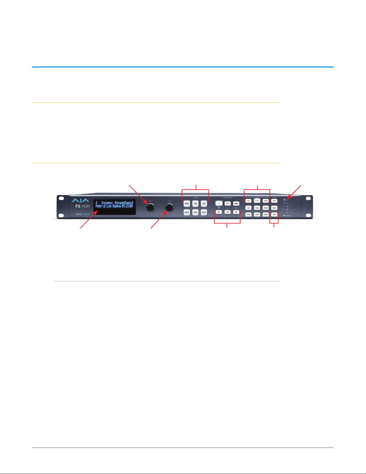
System Selection Buttons:
Select Knob:
Status
Chapter 2 – Controls, Indicators, and Connections
Overview
The controls, indicators, and connectors illustrated and described in this
chapter allow you to connect, operate, and monitor the FS-HDR system and to
troubleshoot problems if you encounter them. Becoming familiar with the front
and rear panels also simplifies system installation, setup, and operation.
Front Panel Description
Press a button to select
Alphanumeric
Display
Scrolls and selects menus.
Push to undo changes.
Adjust Knob:
Changes selected value.
Hold down for default value.
Front Panel Layout and Operation
The FS-HDR’s front panel control system is designed to be quick and easy to use.
The alphanumeric display on the left shows status and parameter information.
SELECT and ADJUST knobs provide fast menu scrolling, parameter selection and
adjustment. Status LEDs on the right report important system information.
The buttons on the front panel operate interactively. At the center of the panel
are System Selection buttons, which provide direct access to parameter menus
that control basic FS-HDR operation (like setting the output frame rate or
selecting Single or Four Channel Mode). In addition, the STATUS button brings
up menus that report FS-HDR status information, and the PRESET button displays
Preset selection menus for rapid reconfiguration. When a System Selection
button is pressed, the parameter menu that was last selected from that group will
be displayed. Pressing any of these buttons de-selects all other SYSTEM buttons,
CHANNEL SELECT buttons, VIDEO menu group buttons, and AUDIO menu group
buttons to the right.
The four VID1-4 Channel Selection buttons to the right allow immediate access
to separate parameter menus for each Video Processor (when in Four Channel
Mode). The button for the currently selected Video Processor is illuminated. In
Single Channel Mode pressing any of the four buttons will light the VID1 button,
indicating that single Video Processor is selected for control. After a Video
a System Category
Channel Selection Buttons:
Press a button to select a
Video Processor or
Type of Audio
(Selection LED Lights)
Video Menu Group
Selection Buttons
Audio Menu Group
Selection Buttons
Indicator
LEDs
FS-HDR Frame Synchronizer/Converter/HDR-WCG Processor v1.0r1 17 www.aja.com
Page 18

Processor has been selected, the nine VIDEO Menu Group buttons on the right
are activated. The VIDEO Menu Group button that was last selected for that Video
Processor will be illuminated, and the alphanumeric display will show the last
selected parameter menu for that Video Menu Group.
Similarly, the EMBED and AES Channel Select buttons selects either Embedded
or AES audio, and activates the three AUDIO Menu Group buttons to the far
right. The last selected AUDIO Menu Group button for that audio type will be
illuminated and its last selected parameter menu will be displayed. Pressing an
Audio Channel Select button de-selects the Video Channel Select button, and
vice-versa.
This design allows rapid menu access, reducing the number of menus to scroll
through, and time is saved when button presses automatically return to their last
selected menus.
Operational Summary
To change FS-HDR operational parameters with the front panel controls:
1. Select a system component and menu group for the alphanumeric display:
• For overall system control, press one of the six SYSTEM buttons,
• For control of a Video Processor, press one of the four VID1-4 Channel Select
buttons and then press one of the VIDEO Menu Select buttons,
• For Embedded audio control, press the EMBED button and then press one
of the AUDIO Menu Select Buttons,
• For AES or MADI audio control, press the AES button and then press one of
the AUDIO Menu Select Buttons.
2. Scroll through menus in a group: Turn SELECT.
3. Edit a menu parameter: Stop SELECT on the menu, then turn ADJUST to set
the value. Changes are applied immediately.
Multiple Part Parameter Editing
To edit a multiple part parameter, such as an IP address,:
1. Push the ADJUST knob momentarily (the value blinks).
2. To save the whole parameter after editing, push ADJUST momentarily again.
Coarse Adjust Editing
To coarse adjust a value (for use with parameters that have more than 10
selections):
• 10x speed - Hold down the SYSTEM or currently active CHANNEL SELECT
button (the button turns dark blue) and turn ADJUST. The values will change
in approximately 10x increments.
• 100x speed (available for extremely wide-range parameters, like Audio Delay)
- After enabling 10x speed above, momentarily release and press that group
button a second time (the button turns light blue). Turning ADJUST will now
change the value in approximately 100x increments.
Undo a Change
To restore a previous setting:
• Push SELECT momentarily.
FS-HDR Frame Synchronizer/Converter/HDR-WCG Processor v1.0r1 18 www.aja.com
Page 19
Reset to Factory Default:
To return to the factory default of a parameter:
• Hold down ADJUST for 4 seconds.
Alphanumeric Display
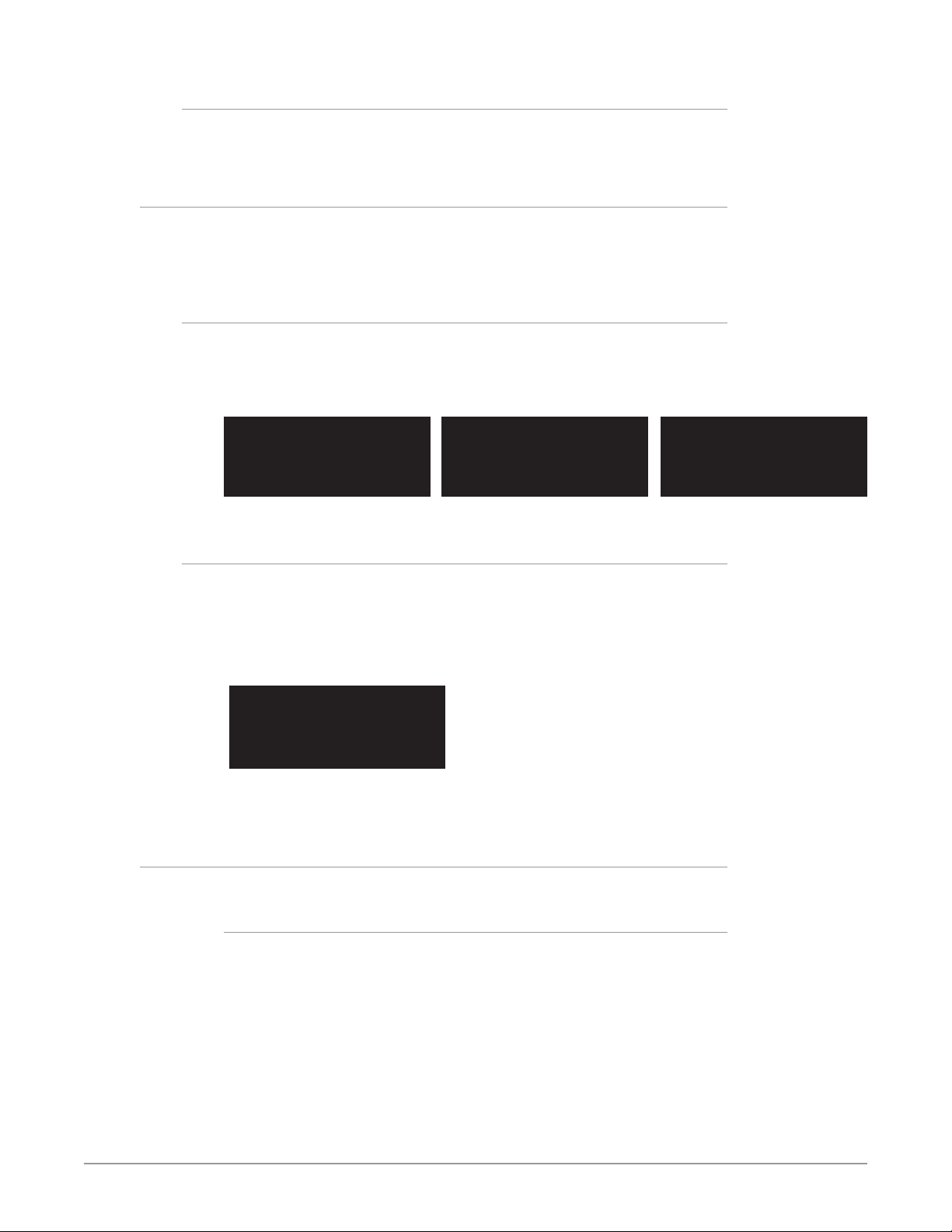
The four-line alphanumeric display shows either status menus that can be
scrolled through but not altered, or parameter adjustment menus that are
numbered and grouped by function, whose parameters can be altered.
Status Menus
Status menus generally have a feature on the left, and the current status or
setting for that feature next to it. Information can generally be shown in two
columns, three columns, or four columns (two columns side by side).
Figure 3. Status Menu Front Panel Displays
System Name
Feature 1 STATUS
Feat2 STATUS
Feat3 STATUS
Parameter Menus
Parameter menu lines display the following information:
• First line—parameter number and name.
• Second line—the editable value set for a parameter.
• Third and fourth lines—current status, labels, or prompts.
Figure 4. Four Lines of the Front Panel Display
1 Param number & name
2 Current value setting
3 Legend, info or prompt
4 Legend, info or prompt
When you edit a parameter containing multiple values, such as the IP address, the
value currently being edited blinks.
Control Knobs
Feature1 SETTING STATUS
Feat2 SETTING STATUS
Feat3 SETTING STATUS
Feat4 SETTING STATUS
Feat1 STATUS Feat5 STATUS
Feat2 STATUS Feat6 STATUS
Feat3 STATUS Feat7 STATUS
Feat4 STATUS Feat8 STATUS
The general rules of SELECT and ADJUST knob operation are:
SELECT
Turning the SELECT knob performs these actions:
• Turn SELECT in either direction to scroll through the menus.
• Stop on a menu to enter that menu for editing.
• Turn SELECT within a menu to scroll through multiple parameters.
• Pause on a parameter to select it for editing. For multiple elds in a parameter,
use SELECT to move through the elds (after pressing ADJUST to enter eld
editing mode).
• Push SELECT momentarily to undo and restore the previous setting.
FS-HDR Frame Synchronizer/Converter/HDR-WCG Processor v1.0r1 19 www.aja.com
Page 20

ADJUST
Turning the ADJUST knob performs these actions:
• Turn ADJUST to change the values of a selected parameter.
• In most cases, leaving a value in place for a moment sets that value.
• To perform special actions, such as recalling a register, push the knob to
conrm the displayed value. Display line 4 indicates such special actions.
• Some parameters having multiple elds, such as IP Address require you to
push the ADJUST knob to select a eld, and push again to save changes.
• Hold down the knob to reset a value to the factory default; for multiple eld
values, all elds are reset to the default.
• When the STATUS button is selected, pressing ADJUST returns the user to the
last mode and menu selected before SYSTEM -> STATUS was selected.
Button Menus
The general functions accessed by the front panel buttons are listed below:
System Buttons
STATUS
Displays the Status Menu Group, which shows current machine status and error
conditions:
• Video Input and status
• Caption status
• Reference and Genlock status
• Output status
• Power and Temperature status
• System Name display
• Alarms
REMOTE
Displays the Remote Menu Group, which lets you select how to control the
FS-HDR:
• Control by local front panel only, remote sources only, or local and remote
• Authentication
• GPI input and output behavior
VIDEO
Displays the System Video Menu Group, which lets you change or enable system
wide video functions:
• Output frame rate selection
• Genlock reference source selection
• Monitor output settings
• Video input format settings, including 3G setup
CONFIG
Displays the Config Menu Group, which lets you configure the FS-HDR for your
environment:
• System Name setting
• FS-HDR Mode (Single Channel or Four Channel)
FS-HDR Frame Synchronizer/Converter/HDR-WCG Processor v1.0r1 20 www.aja.com
Page 21

• IP settings, MAC address
• SNMP settings
• Alarm control
• Hidden Menus, Screen Saver, and Display intensity
• Fan speed
• System serial number and software version
• System reboot
AUDIO
Displays the System Audio Menu Group, which lets you change or enable system
audio functions:
• MADI Output mode
• Audio Input Sample Rate Conversion (Embedded, AES, MADI
• 5.1 and 7.1 Mixdown
• Global Audio Output
• Reset Channel Mapping (Embedded, AES, MADI)
PRESET
Displays the Preset Menu Group, which accesses the memory registers:
• Store, Recall, and edit the names of Presets
• Factory Preset (defaults)
Channel Select Buttons
VID1- 4
Selects which Video Processor the nine VIDEO buttons will access menus for
control. In Single Channel Mode any button can be pressed.
Blue = A valid video source is present.
Red = An invalid video source is detected (unless the alarm has been suppressed,
in which case the LED will be turned off).
Off = No video is present, or invalid video is detected and the alarm is suppressed.
NOTE: The FS-HDR operating mode can be determined by the VID 1-4 button tallies. In
Four Channel Mode all four LEDs light, with the selected Video Processor high
tally. In Single Channel Mode only the VID1 button tally is low tally or high tally.
EMBED
Selects Embedded Audio for control by menus accessed by the three AUDIO
Menu Group buttons.
Blue = Valid embedded audio is present on any video source.
Off = No embedded audio is detected.
AES
Selects AES and MADI for control by menus accessed by the three AUDIO Menu
Group buttons.
Blue = Valid AES or MADI audio is present.
Off = No AES or MADI audio is detected.
FS-HDR Frame Synchronizer/Converter/HDR-WCG Processor v1.0r1 21 www.aja.com
Page 22

Video Menu Group Buttons
INPUT
• Input source selections
• Dynamic Range and Gamut settings
• SDR Highlights settings
• Loss of input selection
• Reverse Telecine
• Input scan format settings (PsF or interlaced)
• Input Image Mapping (Single Channel Mode only)
ANC
• Active Format Descriptor (AFD) settings
• Caption translation selection
• SD line 21 blanking selection
COLOR
• Proc amp settings
• Legalizer settings
FORMAT
• Output format
• Dynamic Range and Gamut settings
• Dynamic Range Clamp selection
• Link Conguration
• SD Aspect Ratio
• Up and Down Convert settings
• Output Image Mapping (Single Channel Mode only)
SCALE
• Custom Size and Position and ROI settings
KEYER
• Background ll selection
• Sidebar Edge
• Matte adjustments
TIMING
• H and V timing and delay settings
TSTGEN
• Test Pattern settings
FREEZE
• Freeze Output setting
Audio Menu Group Buttons
LEVEL
• Audio level and phase settings
FS-HDR Frame Synchronizer/Converter/HDR-WCG Processor v1.0r1 22 www.aja.com
Page 23

DELAY
• Audio delay settings
MAP
• Output mapping controls
Status LED Indicators
Indicators on the front panel are multi-state LEDs that light when a condition is
present. The indicators and the conditions that cause them to light are as follows:
PS1/PS2
• Blue = Power Supply 1 or 2 is operational and receiving power. Both PS1 and
PS2 LEDs must be lit blue to indicate redundant power is available.
• Red = Power supply is not receiving power or not operating within 10% of
nominal value (unless the alarm has been suppressed, in which case the LED
will be turned o).
• O = Power supply alarm is suppressed and nominal power is not being
received.
2SI
• Blue = (Single Ch only) The processor’s output mapping is set to 2SI (2 Sample
Interleave).
• O = In Single Channel Mode the processor’s output mapping is set to
Quadrant (Square Division). In Four Channel Mode this LED is always o.
REF
• Blue = The FS-HDR is operating with a valid reference.
• Red = A reference alarm condition exists (unless the alarm has been
suppressed, in which case the LED will be turned o).
ID
Blinks blue on and off when you right-click on an FS-HDR system name and
choose Identify in the web interface Network list. This action helps identify
which system you’re controlling when multiple units are operated from a single
computer. The ID LEDs on the front and rear panels perform the same function.
No matter which side of a rack you’re facing, you’ll be able to see one of the LEDs.
REMOTE
This multicolor LED indicates the current control mode:
• Blue= Local Only (front panel control only)
• Red = Remote Only (remote browser or panel control only)
• Purple = Local + Remote (front panel and remote control both enabled)
Incompatibility Alarms
The FS-HDR produces signal incompatibility alarms for a number of reasons. For
example, incompatible conversion alarms can occur because the FS-HDR cannot
convert between frame rate families (59.94/29.97/23.98, or 50/25, or 60/30/24).
FS-HDR Frame Synchronizer/Converter/HDR-WCG Processor v1.0r1 23 www.aja.com
Page 24
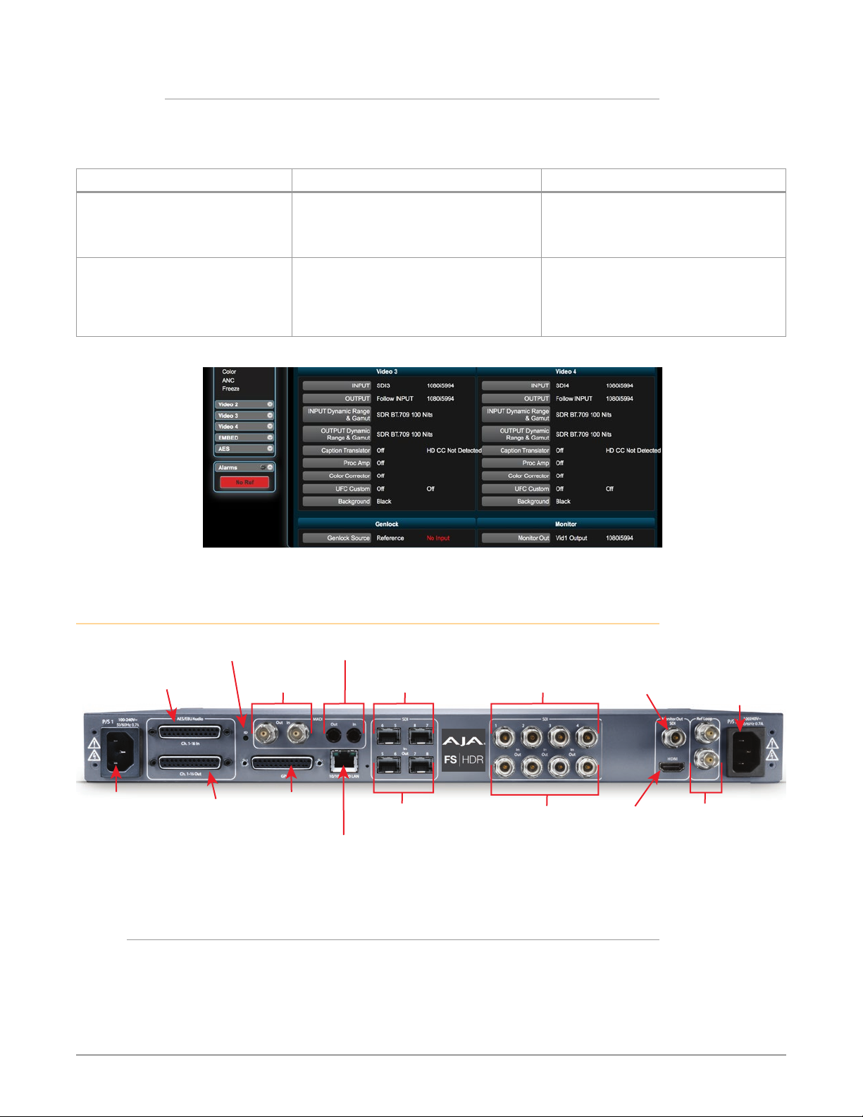
LAN Connector
ID
AC Power
MADI Fiber
AES/EBU Digital
Example Reference and Video Incompatibility Alarms
Video incompatibilities that the FS-HDR may detect include the following
examples:
Table 1. Video Incompatibility Examples
Video Incompatibility Detected Alarm Status screen will show Video Status screen will show
Genlock Source is set to “Reference”,
but no Reference signal is detected.
In this example the cable has been
disconnected.
Reference signal format is not
compatible with selected Output
Format. In this example the
reference signal is 50 Hz but output
is 59.94 Hz.
Figure 5. Web page example of un-supported signals alarm.
IN SDI 1 OK
BKGD Matte OK
GEN Ref No Ref
OUT1 1080i59
IN SDI 1 OK
BKGD Matte OK
GEN Ref incompat
OUT 1080i59
IN SDI 1 1080i59
BKGD Matte
GEN Ref No Input
OUT1 UHDp59
IN SDI 1 1080i59
BKGD Matte
GEN Ref 1080i50
OUT1 UHDp59
Rear Panel Description
LED
Audio Out
The FS-HDR rear panel connectors are summarized below:
DB-25F Connector
AC Power
Socket #1
Autosensing
100 to 240VAC
50/60Hz
Audio In
Channels 1-16
AES/EBU Digital
Channels 1-16
DB-25F Connector
Connectors
MADI BNC
Out/In
GPI 25-pin
DB-25F
Connector
Out/In
10/100/1000
RJ45 Ethernet
SFP Input
SDI 6,5,8,7
SFP Output
SDI 5, 6, 7, 8
SDI 1-4
Input BNCs
SDI 1-4
Output BNCs
Monitor
Output BNC
Monitor
Output HDMI
Socket #2
Autosensing
100 to 240VAC
50/60Hz
External Reference
I/O with looping
BNC connectors.
FS-HDR Frame Synchronizer/Converter/HDR-WCG Processor v1.0r1 24 www.aja.com
Page 25

P/S 1 and P/S 2
Two IEC-60320 3-pin grounded connectors provide AC power to the two
independent power supplies. The supplies are autosensing for 100–240 VAC,
50/60 Hz. Only one connection is required for operation, but both connectors
must be plugged into AC power for redundant power protection.
AES/EBU Digital Audio
Two GPI DB-25F connectors provide input and output of 16 channels of balanced
digital audio. See "Audio Connection Pinouts" on page 129.
MADI BNC
64 channel MADI output and input, on separate BNC connectors.
MADI Fiber
64 channel MADI output and input, on separate Multi-Mode fiber ST connectors.
GPI
The GPI DB-25F connector provides connection to external equipment or circuits
via an isolated TTL-compatible interface. Four GPI inputs and four outputs are
available. See "GPI Pinouts" on page 128 .
Using the REMOTE menu group, you can program the actions of the GPI inputs
and outputs individually. Contact closures on the inputs can trigger a wide variety
of FS-HDR functions. Alarms or loss of video can trigger the GPI outputs.
10/100/1000 LAN
This RJ-45 connector provides an Ethernet 10/100/1000 port for connection
directly to a computer or to a LAN through an Ethernet hub or switch.
SFP In/Out (optional)
All FS-HDR’s optional SFP I/O ports support up to 3G SDI operation. In addition, in
Single Channel mode the FS-HDR‘s SFP ports 5 through 8 In and Out also support
12G and 6GSDI, when equipped with a compatible SFP module.
SDI In/Out
Digital video with embedded audio. Four SDI input and Four SDI Output BNCs.
10 bit 3G SDI is supported. The input and output signals carried on each BNC
connector varies, depending on the link configuration and format selection.
Monitor Output
Two Monitor output connectors are available, BNC (SDI) and HDMI, which output
the same video and audio. In Four Channel Mode you can select which Video
Processor output is sent to both of these Monitor output connectors. Single
Channel Mode always passes the unit’s single output to these connectors, and
4K/UltraHD signals are automatically downconverted to 2K/HD.
NOTE: The BNC and HDMI monitor output cannot directly display 4K/UltraHD signals,
and the HDMI output does not include an HDR infoframe.
4K/Ultra HD and HDR signals can be monitored locally using the FS-HDR's extra
outputs (optional SFP modules required) and AJA Hi5-4K Mini-Converters. See
"Local Monitoring with the FS-HDR" on page 39 for more information.
FS-HDR Frame Synchronizer/Converter/HDR-WCG Processor v1.0r1 25 www.aja.com
Page 26

Ref Loop
The Reference Loop BNCs accept an Output timing reference signal. The
reference can be analog SD blackburst or HD tri-level sync. Examples of
permissible reference video input signals:
• 525 Color Black
• 625 Color Black
• 1080i Tri-level Sync
• 720p Tri-level Sync
The 2 BNCs are a passive loop: one BNC is for the Input, and the remaining BNC
can be connected to another piece of equipment in the reference chain or
terminated.
NOTE: For proper operation the input Reference signal must be stable and properly
terminated using a 75-ohm terminator on either the unused loop connector or
the last piece of downstream equipment to which the Ref Video is connected.
FS-HDR Frame Synchronizer/Converter/HDR-WCG Processor v1.0r1 26 www.aja.com
Page 27
Chapter 3 – Installation & Configuration
Installation Overview
The installation and set up of an FS-HDR is very simple. Plug both AC supply
cords into AC mains power (separate branch circuits for redundancy), connect the
LAN connector to a LAN, WAN or local computer with a web-browser, and then
connect source and destination video and audio equipment.
NOTE: The AJA FS-HDR should be plugged into 3-wire 100-240 VAC 50/60 Hz power
(autosensing) before you make connections to other equipment. The AC cords
provide a path to ground for accidental static discharge to protect system
equipment. The unit has two fully independent and redundant power supplies
and will operate with one or both AC power cords plugged into the unit. However,
fault-tolerance exists only if both power supplies are connected and plugged into
separate branch circuits. Then if power is lost on a branch or one of the supplies,
the unit will continue to operate on the remaining circuit and power supply.
Warning! To meet safety regulations for leakage current and to ensure redundancy
in the event that a branch circuit breaker shuts o a branch, connect the dual
power supplies to separate branch circuits.
Installation Summary
All the steps of installation and configuration are documented in this chapter and
are summarized as follows:
1. Unpack the shipping box, removing the FS-HDR and two power cords.
2. Install any physical options, such as SFP I/O modules.
3. Mount the physical chassis as desired: front rack, rear rack, or desk mount.
If you are mounting multiple FS-HDR units, try to place them visually in the
same area so you can use an attached computer to turn on and see the ID
LED of the FS-HDR you’re communicating with. For physical installation
details see "FS-HDR Chassis Installation" on page 28.
4. Connect the two FS-HDR power cords to mains AC. For redundancy, use
both power supplies and connect them to separate branch circuits so that
the FS-HDR will continue to operate even if a circuit breaker opens on one
branch.
5. If you plan to use remote control, connect your computer to the FS-HDR
directly using an Ethernet cable, or connect both the computer and the
FS-HDR to a local area network through an appropriate hub or router. Also
set the FS-HDR IP address in the menus, and then use a computer to test
(ping) the FS-HDR over the network connection to verify communication.
For details, see "Networking" on page 29.
6. Install a web browser on the computer, if not already present, for accessing
the FS-HDR web pages. You can access the pages simply by entering the
FS-HDR IP address in the browser address eld. See "Web Browser Control" on
page 31.
7. Connect the FS-HDR to system audio and video sources, including VTRs,
monitors, DVD players, video switchers, and audio mixers. For details,
see"System Cabling" on page 33
8. Test the FS-HDR with all of your devices to verify everything is working.
FS-HDR Frame Synchronizer/Converter/HDR-WCG Processor v1.0r1 27 www.aja.com
Page 28

Unpacking
Shipping Box Contents
An FS-HDR chassis is shipped with two AC power cords and any late-breaking
news bulletins (if applicable). Chassis rackmount brackets are provided as part of
the chassis with screws.
As you unpack the shipping box, carefully examine the contents. Ensure you
received everything and that nothing was damaged during shipment. If you find
any damage, immediately notify the shipping service and supply them with a
complete description of the damage. AJA will repair or replace damaged items.
If you find shipping damage, contact your AJA dealer or distributor for details on
how to have your FS-HDR repaired or replaced.
NOTE: Save packing materials and the shipping box. If your FS-HDR ever requires service
or you move your system, use the packaging materials and box for safe shipment.
Installing Optional SFP I/O Modules
The optional AJA SFP I/O modules are purchased separately from the FS-HDR.
Install the optional SFP I/O modules by inserting them into the rectangular cages
on the back panel with the electrical connectors facing downward. Press gently
but firmly until the modules seat in the inside connectors.
You must remove any connected fiber or coaxial cables from the SFP modules
before you remove the modules from the FS-HDR. Pull down the SFP lever to free
the module before you withdraw the module from the cage.
For additional installation and operation details, see the instructions provided
with the SFP modules.
FS-HDR Chassis Installation
The following information will help you install the FS-HDR chassis correctly.
Physical Requirements for Mounting the Chassis
You can mount the FS-HDR chassis in two ways:
• Rackmounting—attach the FS-HDR (rear or front mounted) to a standard 19inch wide equipment rack. The chassis occupies only one vertical rack unit.
• Desktop—lay it on a horizontal at surface.
Chassis Dimensions
When planning the equipment location, consider the chassis dimensions:
• Height—1 rack unit, 1.75 inches (4.5 cm)
• Depth—16 inches (40.65 cm)
• Width—17.5 inches (44.45cm)
• Weight—7.85 pounds, 3.56 kilograms
Cabling and Cooling Requirements
Observe these precautions when placing your FS-HDR:
FS-HDR Frame Synchronizer/Converter/HDR-WCG Processor v1.0r1 28 www.aja.com
Page 29

NOTE: FS-HDR units can be stacked vertically without limit as long as there is an
Power Requirements
Networking
• Plan adequate space for cable routing from the back of the chassis. Ensure that
cable connectors are not stressed and cables are not bent or crimped.
• When rack mounting or stacking multiple FS-HDR chassis, ensure adequate
airspace for cooling around the FS-HDR units. Note the location of cooling
vents on all equipment next to the FS-HDR and ensure none are obstructed.
adequate supply of cool air around the FS-HDR side vents.
The FS-HDR requires the following input voltage and power.
• Input Voltage—Chassis: autosensing 100VAC to 240VAC, 50/60Hz,
fully redundant with both power supplies diode isolated.
• Power Consumption—55 Watts (70 Watts maximum)
You can network the FS-HDR directly to a laptop or other desktop computer
using a single Ethernet cable (straight or cross-over), or connect it to a local area
network (LAN). In either case, the FS-HDR connects via its 10/100/1000 Base-TX
Ethernet connector. A LAN is a shared network that includes other Ethernet
devices all attached via a hub or digital switch. LANs may be divided into zones
separated by software or hardware routers. Routers may also be used to connect
the LAN to an outside wide area network (WAN) such as the internet.
Devices on a LAN have IP addresses which may be fixed and permanent or
dynamically assigned by the network (DHCP). When attaching the FS-HDR to a
LAN, talk to your network administrator to find out how they want it connected
(static IP or DHCP). Your IT department will be able to supply the information you
need to install the FS-HDR on a LAN.
FS-HDR Default Network Settings
The FS-HDR ships from the factory set for DHCP networking, and can be manually
reset to the following default network settings:
IP Address 192.168.0.2
Subnet Mask 255.255.255.0
Gateway 192.168.0.1
The following topics discuss two ways to set up the unit to communicate over a
TCP/IP network connection: via DHCP or via a static IP address.
Networking Using DHCP or Default Static IP
The FS-HDR factory default configuration automatically looks for a DHCP server
to issue an IP address. If your network includes a DHCP server, plug the FS-HDR
into the network and connect with the unit as follows:
1. Press the CONFIG button.
2. Turn the SELECT knob to navigate to cong parameter 3.2. Note on a piece
of paper the DHCP-supplied IP address shown.
3. With your laptop or desktop computer connected to the same LAN as the
FS-HDR and DHCP enabled, launch a web browser, type the IP address you
noted on the FS-HDR’s display into the browser address eld and press
Enter. You should now see the FS-HDR’s browser Status screen.
FS-HDR Frame Synchronizer/Converter/HDR-WCG Processor v1.0r1 29 www.aja.com
Page 30

If the FS-HDR cannot get an IP address from the network DHCP server, the FS-HDR
will automatically use a preset factory static IP address of 192.168.0.2. You can
access the FS-HDR using the default static address as follows:
1. Set your computer’s IP address to whatever address you prefer in the
192.168.0 (class C) network.
2. Set the computer’s Subnet mask to 255.255.255.0 (most PCs default to the
proper netmask when the address is set).
3. Set the gateway address, if used, to match the FS-HDR default: 192.168.0.1.
Alternatively, change the FS-HDR gateway address to match your gateway:
A. Press CONFIG, turn SELECT to 3.4 Default Gateway, push and then turn
ADJUST to change the rst group of digits.
B. Turn SELECT to advance to the next set of numbers, and turn ADJUST to set
these numbers.
C. Continue using SELECT and ADJUST to set the full address.
D. When nished, push ADJUST momentarily to save the address.
5. Run a browser on the computer and type “192.168.0.2” (the factory static IP
address). You should now see the FS-HDR’s browser status screen.
When you can access the FS-HDR screens, see "Browser Remote Control" on page
97 for details about configuring the FS-HDR using a browser.
Networking the FS-HDR Using Your Own Static IP
If you don’t want to use DHCP or the default static IP address, you can set your
own static IP address:
1. Select the CONFIG button and use the SELECT knob to navigate to
parameter 2.1 IP CONFIG. Use the ADJUST knob to select Static.
2. Turn SELECT to navigate to parameter 3.2 IP ADDRESS. The display shows
the default static IP address: 192.168.0.2.
3. Change the IP address as follows.
A. Push the ADJUST knob momentarily so that the rst octet (set of numbers)
blinks, and then turn ADJUST to change the numbers.
B. Turn SELECT to advance to the next set of numbers, and turn ADJUST to set
these numbers.
C. Continue using SELECT and ADJUST to set the full address.
D. When nished, push ADJUST momentarily to save the address.
5. Turn SELECT to advance to 3.3 Subnet Mask. Use the SELECT and ADJUST
knobs as in the previous step to set the desired subnet mask.
6. Turn SELECT to advance to 3.4 Default Gateway. Use the SELECT and ADJUST
knobs as in the previous step to set the desired gateway address.
7. Run a browser on the computer and type in the IP address you set for the
FS-HDR. You should now see the FS-HDR’s Status screen.
When you can access the FS-HDR screens, see "Browser Remote Control" on page
97 for details about configuring the FS-HDR using a browser.
Using Ping to Test the Network Connection
If you have connected the FS-HDR to a computer and set up the IP address and
still do not see the FS-HDR screens in your browser, you can ping the network to
verify the connection. Simply run the Ping utility from a Mac OS X or Windows
PC computer attached directly or on the same LAN as the FS-HDR as described
below:
FS-HDR Frame Synchronizer/Converter/HDR-WCG Processor v1.0r1 30 www.aja.com
Page 31

Mac Ping Procedure
1. Find the Utilities Folder inside of the Applications Folder.
2. Locate the “Terminal” utility application and double-click it.
3. On the FS-HDR, select the STATUS button and go to System Status menu
(with the FS-HDR name) to read the unit’s currently congured IP address.
NOTE: The STATUS menu always shows the FS-HDR’s current IP address. The IP address
on the CONFIG menu is a database entry, which occasionally may not be the
address the unit is using.
4. At the Mac terminal prompt, enter ping and the IP address noted in Step 3
above. For example: ping 192.168.0.2 (and press Return).
5. If successful, the ping utility will respond that packets were sent, received
and how long it took. For example:
64 bytes from 192.168.0.2: icmp_seq=0 ttl=64 time=0.590 ms
6. If unsuccessful, check the FS-HDR network settings and resolve the problem
with your IT administrator.
Windows PC Ping Procedure
1. From the Start button, select the All Programs menu.
2. Select Accessories/Command Prompt from the All Programs list.
3. On the FS-HDR, select the STATUS button and go to System Status menu
(with the FS-HDR name) to read the unit’s currently congured IP address.
NOTE: The STATUS menu always shows the FS-HDR’s current IP address. The IP address
on the CONFIG menu is a database entry, which occasionally may not be the
address the unit is using.
4. In the PC Command Prompt utility, enter ping and the IP address noted in
step 3. For example: ping 192.168.0.2 (and press Return)
5. If successful, the ping utility will respond that packets were sent, received
and how long it took. For example:
64 bytes from 192.168.0.2: icmp_seq=0 ttl=64 time=0.590 ms
6. If unsuccessful, check the FS-HDR network settings and resolve the problem
with your IT administrator.
Web Browser Control
To control the FS-HDR from a web browser on a network attached computer,
enter the FS-HDR IP address as a URL in the browser. For example, if the
FS-HDR IP address were “90.0.6.31”, you would then type into the web browser:
http://90.0.6.31. This topic is explained in greater detail in Chapter 5: Browser
Remote Control.
NOTE: The web UI (browser GUI) will keep up with most changes initiated at the front
panel. However, the web UI may not reconnect (displays “Disconnected”) when
network changes are initiated at the FS-HDR front panel. To manually reconnect,
type the new IP address into the browser, or click the browser Refresh button.
Sometimes the browser caches the old FS-HDR address. If you can’t get the
browser to connect, try clearing the Browser history to clear the cache, and then
enter the new address again.
FS-HDR Frame Synchronizer/Converter/HDR-WCG Processor v1.0r1 31 www.aja.com
Page 32
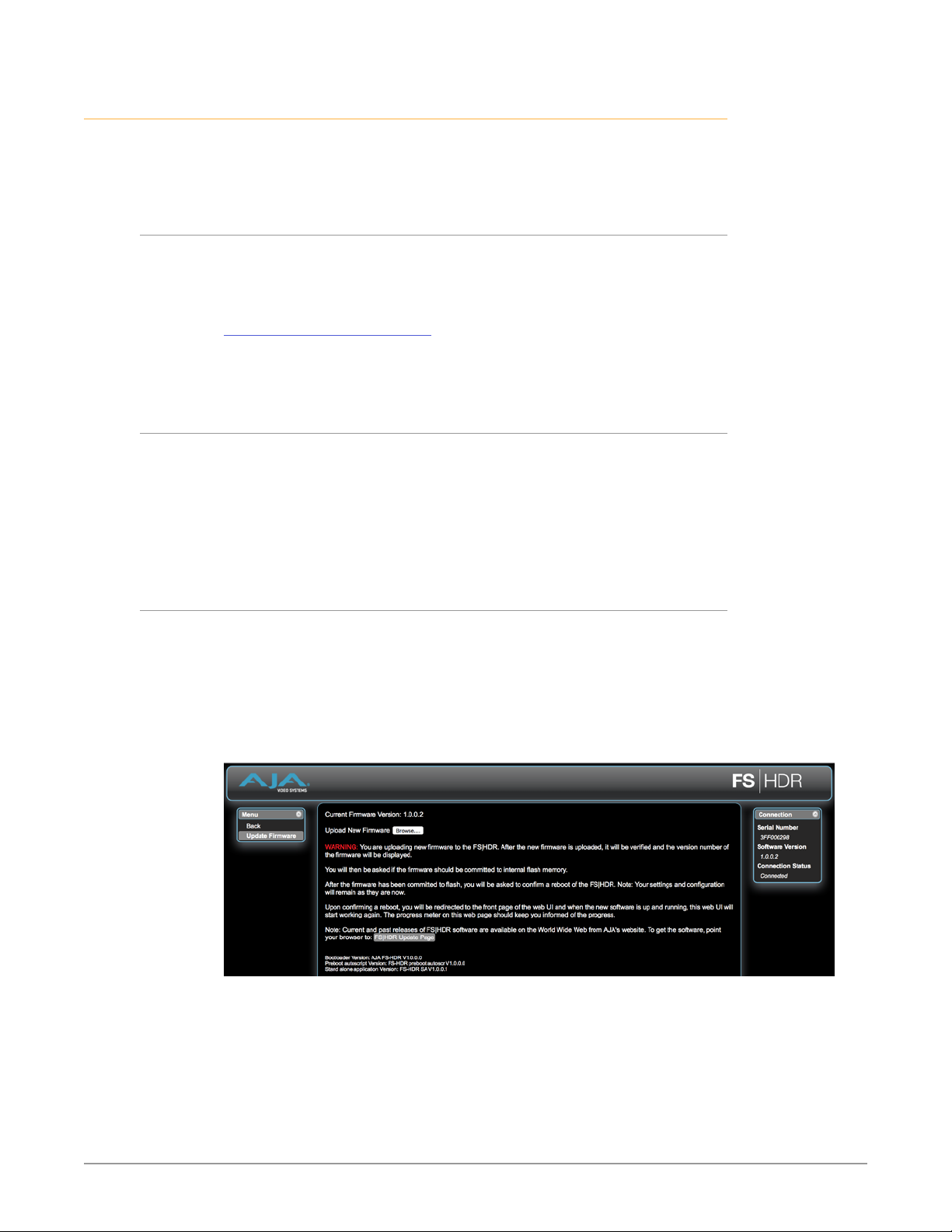
Software Update Installation
Although the FS-HDR comes from the factory pre-installed with software, it may
not be as up-to-date as software posted on the AJA website. This topic describes
the steps required to update the software in your AJA FS-HDR.
Download the Latest Software
Current and past releases of FS-HDR software are available on the World Wide
Web from AJA’s website. To get the software, point your browser to the FS-HDR
support page, which will contain helpful FS-HDR information and links to the
updates.
https://www.aja.com/en/family/fs
Once you’re at the update page, you can select FS-HDR software files to
download to your Mac or PC for upgrading your local FS-HDR machine.
Unpack the Software
FS-HDR software update files are “ZIP” files that you can open with a number of
standard and third party file compression applications. The software image that
you’ll install on the FS-HDR is a file with a name like FS-HDR_ver_1.0.0.0.bin or
similar.
NOTE: Depending on your PC or Mac operating system settings, the “.bin” extension
may not be visible to you in a file directory.
Uploading and Installing the Software to the FS-HDR
Uploading and installing the software update requires a PC or Mac that can
“see” the FS-HDR via its Ethernet connection. Follow this procedure to install the
software:
1. Point your browser at the FS-HDR’s upgrade page by clicking on the
Firmware link at the bottom of the navigation box on the left-hand side of
any FS-HDR web page. The FS-HDR web pages are discussed in Chapter 5.
Figure 6. Update Firmware Browser Screen
2. Click the Browse... button to nd and select the downloaded le. For
example: FS-HDR_ver_1.0.0.10.bin contained in the le downloaded from
AJA.
3. Click OK when asked if you want to Upload Firmware. The le uploads to
the FS-HDR and is tested for validity. Incomplete, corrupted, or non-FS-HDR
les are rejected. Wait for the procedure to complete—it will take only a few
minutes. Progress bars show upload progress.
FS-HDR Frame Synchronizer/Converter/HDR-WCG Processor v1.0r1 32 www.aja.com
Page 33
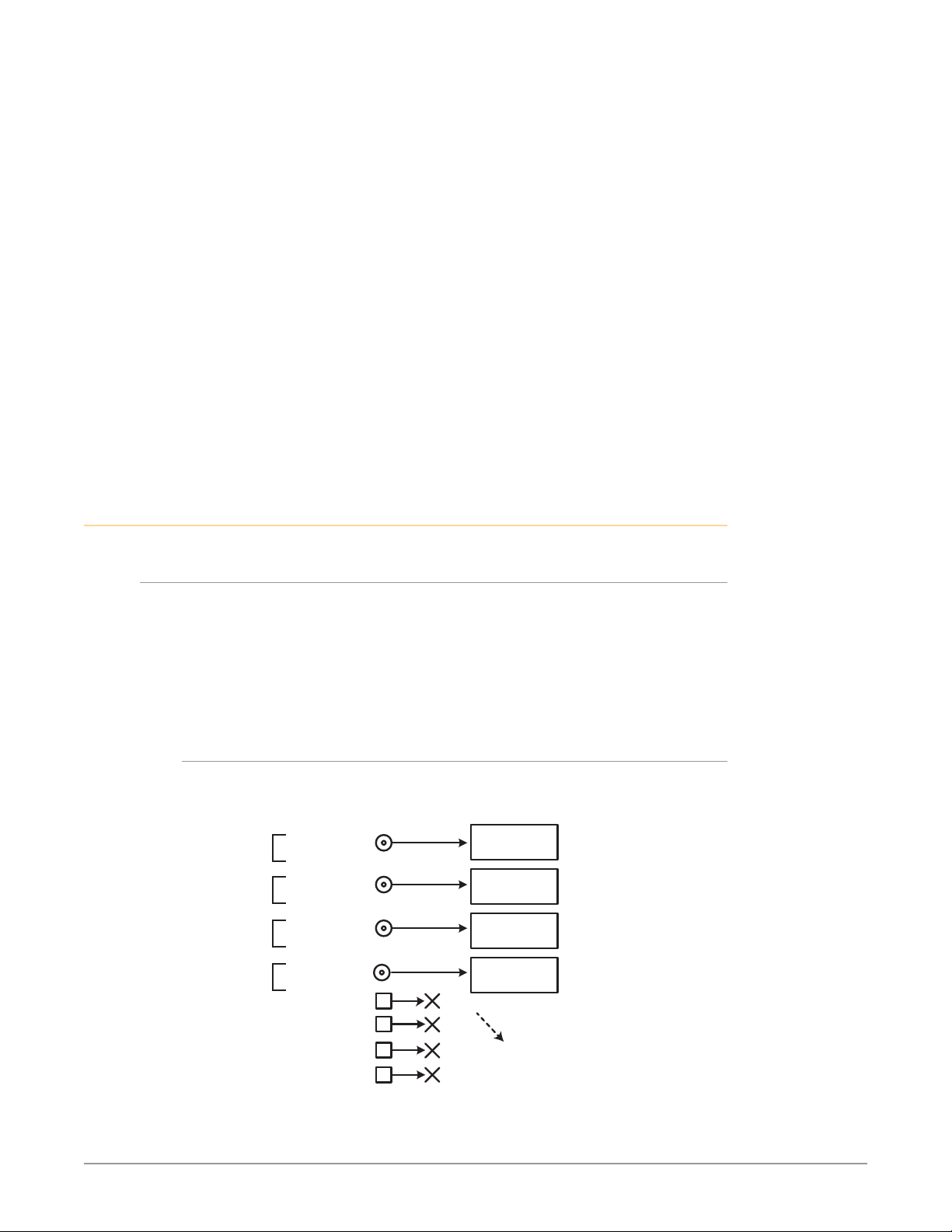
audio is disembedded and
sent to Audio Processor
Signal W
Four Channel Mode
4. Click Commit Uploaded Firmware when prompted after the upload is
nished. Progress bars show progress as the le is written to ash memory.
5. Click Restart FS-HDR with New Firmware to restart the FS-HDR. This will
take the FS-HDR oine for a minute or two. During the restart, progress is
shown in the connection area in the upper right corner of the FS-HDR Status
screen. After restart, the FS-HDR will be running the new software.
6. Once these steps are complete, the FS-HDR will be running the software,
and the Software Version on the Status screen shows the new version
number. Check that the new software is running by bringing up the FS-HDR
web page again; the software version is displayed at the top of all FS-HDR
web screens. If the FS-HDR did not update successfully, run through the
update steps again.
NOTE: The configuration of the FS-HDR prior to the upgrade is preserved. The unit
returns to service exactly as it was before the upgrade.
If there is a power outage or glitch during the software download, the FS-HDR
will boot the older software version and you can restart the upgrade process. This
happens because the FS-HDR has been designed with a safety feature where an
internal “safe” copy of the previous software is retained in the event the updating
process fails.
System Cabling
Four Channel Mode Configuration Examples
In Four Channel Mode each Video Processor can receive a different video signal
and independently process that signal. All incoming embedded audio, even on
inputs not routed to a Video Processor, are disembedded and sent to the Audio
Processor.
NOTE: In the following examples, U, V, W, X, Y, and Z represent different complete
signals, which may be carried on one or more connectors.
Four Channel Mode Input Examples
Figure 7. Four Channel Mode, Four BNC Inputs
Signal X
Signal Y
Signal Z
BNC Input
SDI !n 1 BNC
(w Embedded Audio)
SDI !n 2 BNC
(w Embedded Audio)
SDI !n 3 BNC BNC
(w Embedded Audio)
SDI !n 4 BNC
(w Embedded Audio)
SDI In 5 SFP
SDI In 6 SFP
SDI In 7 SFP
SDI In 8 SFP
HD/SD
Video Processor 1
HD/SD
Video Processor 2
HD/SD
Video Processor 3
HD/SD
Video Processor 4
All incoming embedded
FS-HDR Frame Synchronizer/Converter/HDR-WCG Processor v1.0r1 33 www.aja.com
Page 34
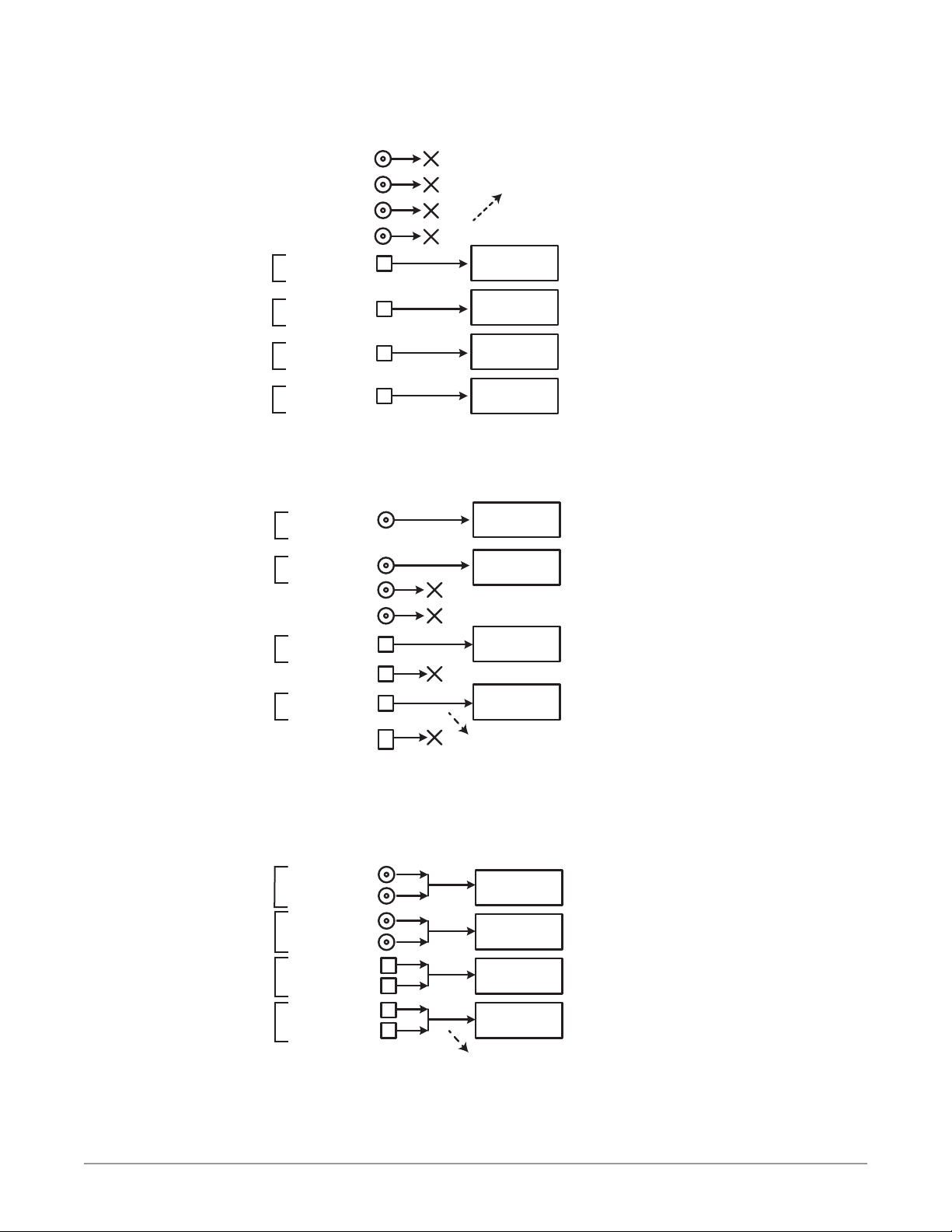
Four Channel Mode
audio is disembedded and
Signal W
audio is disembedded and
sent to Audio Processor
Four Channel Mode
Signal W
audio is disembedded and
sent to Audio Processor
Signal W
Four Channel Mode
Figure 8. Four Channel Mode, Four SFP Inputs
SFP Input
SDI In 1 BNC
SDI In 2 BNC
SDI In 3 BNC
SDI In 4 BNC
SDI In 5 SFP
(w Embedded Audio)
All incoming embedded
sent to Audio Processor
HD/SD
Video Processor 1
Signal X
Signal Y
Signal Z
SDI In 6 SFP
(w Embedded Audio)
SDI In 7 SFP
(w Embedded Audio)
SDI In 8 SFP
(w Embedded Audio)
HD/SD
Video Processor 2
HD/SD
Video Processor 3
HD/SD
Video Processor 4
Figure 9. Four Channel Mode, BNC and SFP Inputs
BNC & SFP Inputs
HD/SD
Video Processor 1
HD/SD
Video Processor 2
HD/SD
Video Processor 3
HD/SD
Video Processor 4
All incoming embedded
Signal X
Signal Y
Signal Z
SDI In 1 BNC
(w Embedded Audio)
SDI In 2 BNC
(w Embedded Audio)
SDI In 3 BNC
SDI In 4 BNC
SDI In 5 SFP
(w Embedded Audio)
SDI In 6 SFP
SDI In 7 SFP
(w Embedded Audio)
SDI In 8 SFP
Figure 10. Four Channel Mode, Dual Link Inputs
BNC & SFP Dual LInk Input
SDI In 1 BNC
(w Embedded Audio)
SDI In 2 BNC
(w Embedded Audio)
SDI In 3 BNC
Signal X
Signal Y
Signal Z
(w Embedded Audio)
SDI In 4 BNC
(w Embedded Audio)
SDI In 5 SFP
(w Embedded Audio)
SDI In 6 SFP
(w Embedded Audio)
SDI In 7 SFP
(w Embedded Audio)
SDI In 8 SFP
(w Embedded Audio)
FS-HDR Frame Synchronizer/Converter/HDR-WCG Processor v1.0r1 34 www.aja.com
HD/SD
Video Processor 1
HD/SD
Video Processor 2
HD/SD
Video Processor 3
HD/SD
Video Processor 4
All incoming embedded
Page 35
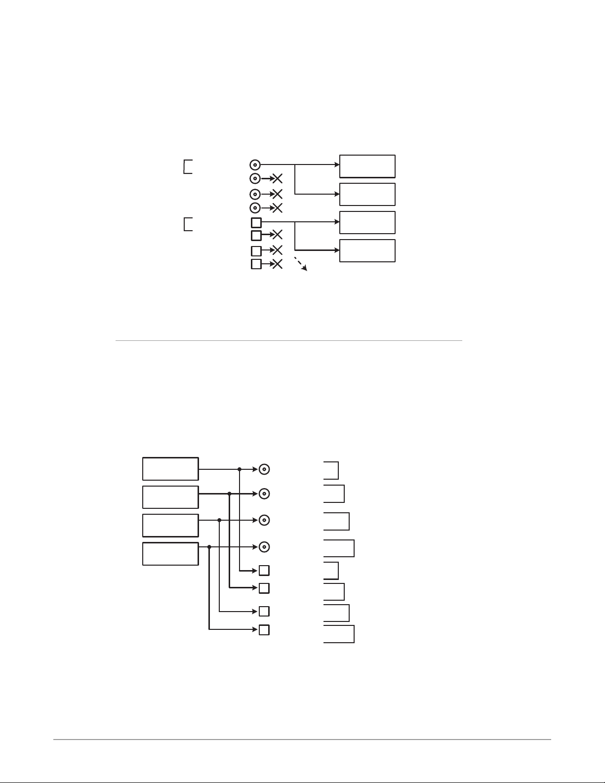
sent to Audio Processor
Dual Stream
Dual Stream
Four Channel Mode
duplicated once
Four Channel Mode
For Dual Stream input, two independent video image signals are transported
over a single link (SDI-A and SDI-B). Each video image requires a separate Video
Processor, so a total of two Dual Stream signals can be received for processing.
Sixteen channels of embedded audio can be carried on each video signal, so up
to 64 embedded audio channels can be routed to the FS-HDR Audio Processor.
Figure 11. Four Channel Mode, Dual Stream Inputs
BNC & SFP Dual Stream Input
Signal Y
Signal Z
SDI In 1 BNC
(w Embedded Audio)
SDI In 2 BNC
SDI In 3 BNC
SDI In 4 BNC
SDI In 5 SFP
(w Embedded Audio)
SDI In 6 SFP
SDI In 7 SFP
SDI In 8 SFP
SDI-A
SDI-B
SDI-A
SDI-B
All incoming embedded
audio is disembedded and
HD/SD
Video Processor 1
HD/SD
Video Processor 2
HD/SD
Video Processor 3
HD/SD
Video Processor 4
Four Channel Mode Output Examples
In Four Channel Mode each Video Processor can output a different processed
video signal. Depending on configuration, output signals can be duplicated on
additional available output connectors.
The video output signal from each Video Processor can also carry embedded
audio on the first link of that signal. When video signals are duplicated, the first
link of that duplicated video signal will also carry that same embedded audio.
Figure 12. Four Channel Mode, Single Link Outputs
Single Link Output
HD/SD
Video Processor 1
HD/SD
Video Processor 2
HD/SD
Video Processor 3
HD/SD
Video Processor 4
SDI Out 1 BNC
(w Embedded Audio)
SDI Out 2 BNC
(w Embedded Audio)
SDI Out 3 BNC
(w Embedded Audio)
SDI Out 4 BNC
(w Embedded Audio)
SDI Out 5 SFP
(w Embedded Audio)
SDI Out 6 SFP
(w Embedded Audio)
SDI Out 7 SFP
(w Embedded Audio)
SDI Out 8 SFP
(w Embedded Audio)
Signal W
Signal X
Signal Y
Signal Z
Signal W
Signal X
Signal Y
Signal Z
Four dierent
signals each
FS-HDR Frame Synchronizer/Converter/HDR-WCG Processor v1.0r1 35 www.aja.com
Page 36
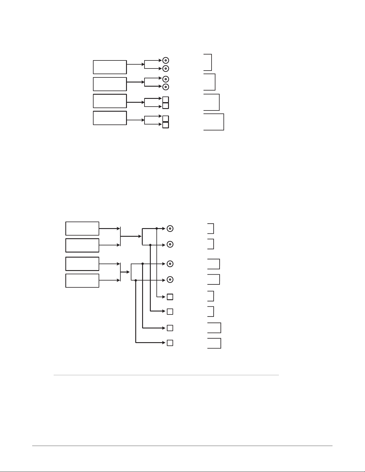
putputs each
Four Channel Mode
Figure 13. Four Channel Mode, Dual Link Outputs
Four Channel Mode
Dual Link Output
SDI Out 1 BNC
HD/SD
Video Processor 1
HD/SD
Video Processor 2
HD/SD
Video Processor 3
HD/SD
Video Processor 4
(w Embedded Audio)
SDI Out 2 BNC
SDI Out 3 BNC
(w Embedded Audio)
SDI Out 4 BNC
SDI Out 5 SFP
(w Embedded Audio)
SDI Out 6 SFP
SDI Out 7 SFP
(w Embedded Audio)
SDI Out 8 SFP
For Dual Stream output, video images from two Video Processors can feed a
single output connector, so two different Dual Stream signals can be output. A
Dual Stream signal carries two video images (SDI-A and SDI-B).
The FS-HDR can also be configured to route only the Dual Stream SDI-A or SDI-B
video image signal to an output connector.
Sixteen channels of embedded audio can be carried on each video signal, so each
Dual Stream output can carry up to 32 embedded audio channels.
Signal W
Signal X
Signal Y
Four dierent
signals not
duplicated
Signal Z
Figure 14. Four Channel Mode, Dual Stream Outputs
Dual Stream Output
HD/SD
Video Processor 1
HD/SD
Video Processor 2
HD/SD
Video Processor 3
HD/SD
Video Processor 4
SDI-A
SDI-B
SDI-A
SDI-B
SDI Out 1 BNC
(w Embedded Audio)
SDI Out 2 BNC
(w Embedded Audio)
SDI Out 3 BNC
(w Embedded Audio)
SDI Out 4 BNC
(w Embedded Audio)
SDI Out 5 SFP
(w Embedded Audio)
SDI Out 6 SFP
(w Embedded Audio)
SDI Out 7 SFP
(w Embedded Audio)
SDI Out 8
(w Embedded Audio)
Signal Y
Dual Stream (SDI-A + SDI-B)
Signal Y
Dual Stream (SDI-A + SDI-B)
Signal Y
Dual Stream (SDI-A + SDI-B)
Signal Y
Dual Stream (SDI-A + SDI-B)
Single Channel Mode Configuration Examples
Signal Z
Dual Stream (SDI-A + SDI-B)
Signal Z
Dual Stream (SDI-A + SDI-B)
Signal Z
Dual Stream (SDI-A + SDI-B)
Signal Z
Dual Stream (SDI-A + SDI-B)
Two dierent
Dual Stream
duplicated
four times
Single Channel Mode has one 4K/UltraHD Video Processor, and all incoming
video is routed to that processor. All incoming embedded audio, even on inputs
not routed to the Video Processor, are disembedded and sent to the Audio
Processor.
FS-HDR Frame Synchronizer/Converter/HDR-WCG Processor v1.0r1 36 www.aja.com
Page 37
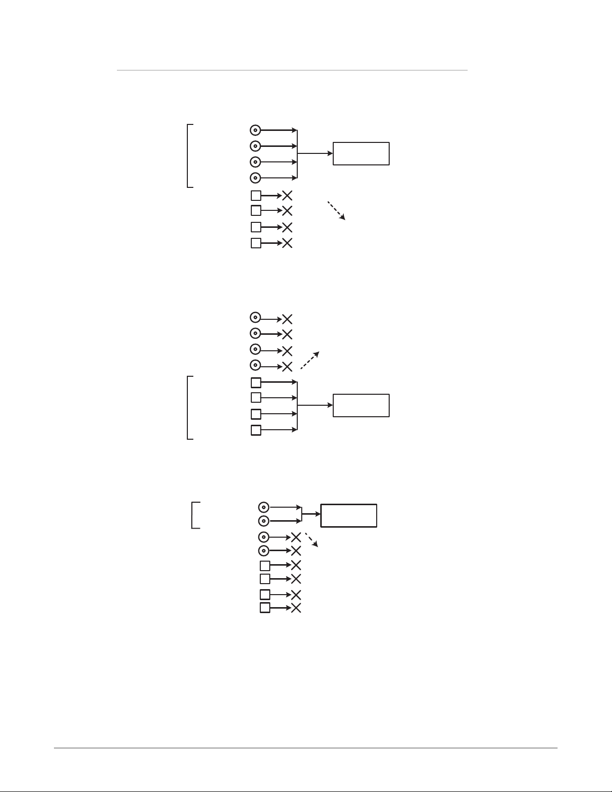
Single Channel Mode Input Examples
Figure 15. Single Channel Mode, 1-4 Quad Link BNC Input
Single Channel Mode
1-4 Quad LInk Input
SDI In 1 BNC
(w Embedded Audio)
SDI In 2 BNC
Signal Z
Figure 16. Single Channel Mode, 5-8 Quad Link SFP Input
(w Embedded Audio)
SDI In 3 BNC
(w Embedded Audio)
SDI In 4 BNC
(w Embedded Audio)
SDI In 5 SFP
SDI In 6 SFP
SDI In 7 SFP
SDI In 8 SFP
Single Channel Mode
5-8 Quad LInk Input
All incoming embedded
audio is disembedded and
sent to Audio Processor
4K/UHD
Video Processor
Signal Z
SDI In 1 BNC
SDI In 2 BNC
SDI In 3 BNC
SDI In 4 BNC
SDI In 5 SFP
(w Embedded Audio)
SDI In 6 SFP
(w Embedded Audio)
SDI In 7 SFP
(w Embedded Audio)
SDI In 8 SFP
(w Embedded Audio)
All incoming embedded
audio is disembedded and
sent to Audio Processor
Figure 17. Single Channel Mode, Dual Link Input
Single Channel Mode
Dual Link Input
SDI In 1 BNC
Signal Z
(w Embedded Audio)
SDI In 2 BNC
(w Embedded Audio)
SDI In 3 BNC
SDI In 4 BNC
SDI In 5 SFP
SDI In 6 SFP
SDI In 7 SFP
SDI In 8 SFP
Video Processor
All incoming embedded
audio is disembedded and
sent to Audio Processor
4K/UHD
Video Processor
4K/UHD
FS-HDR Frame Synchronizer/Converter/HDR-WCG Processor v1.0r1 37 www.aja.com
Page 38
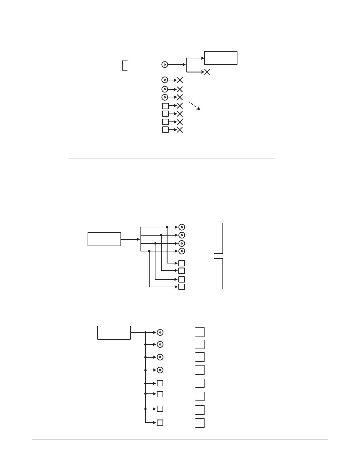
Figure 18. Single Channel Mode, Dual Stream Input
Single Channel Mode
Signal Z
Dual Stream
Dual Stream Input
SDI In 1 BNC
(w Embedded Audio)
SDI In 2 BNC
SDI In 3 BNC
SDI In 4 BNC
SDI In 5 SFP
SDI In 6 SFP
SDI In 7 SFP
SDI In 8 SFP
SDI-A
SDI-B
audio is disembedded and
4K/UHD
Video Processor
Only one of the
Dual Streams
is routed to the
Video Processor
All incoming embedded
sent to Audio Processor
Single Channel Mode Output Examples
In Single Channel Mode, depending on configuration, output signals can be
duplicated on additional available output connectors.
The video output signal from the Video Processor can also carry embedded audio
on the first link of that signal. When video signals are duplicated, the first link of
that duplicated video signal will also carry that same embedded audio.
Figure 19. Single Channel Mode, Quad Link Outputs
Single Channel Mode
Quad Link Output
4K/UHD
Video Processor
SDI Out 1 BNC
(w Embedded Audio)
SDI Out 2 BNC
SDI Out 3 BNC
SDI Out 4 BNC
SDI Out 5 SFP
(w Embedded Audio)
SDI Out 6 SFP
SDI Out 7 SFP
SDI Out 8 SFP
Figure 20. Single Channel Mode, Single Link Outputs
Single Channel Mode
Single Link Output
4K/UHD
Video Processor
SDI Out 1 BNC
(w Embedded Audio)
SDI Out 2 BNC
(w Embedded Audio)
SDI Out 3 BNC
(w Embedded Audio)
SDI Out 4 BNC
(w Embedded Audio)
SDI Out 5 SFP
(w Embedded Audio)
SDI Out 6 SFP
(w Embedded Audio)
SDI Out 7 SFP
(w Embedded Audio)
Signal Z
Signal Z
Signal Z
Signal Z
Signal Z
Signal Z
Signal Z
Signal Z
Two copies of the
same signal on the
BNC and SFP outputs
Signal Z
Eight copies of
the same signal
on all outputs
SDI Out 8 SFP
(w Embedded Audio)
Signal Z
FS-HDR Frame Synchronizer/Converter/HDR-WCG Processor v1.0r1 38 www.aja.com
Page 39
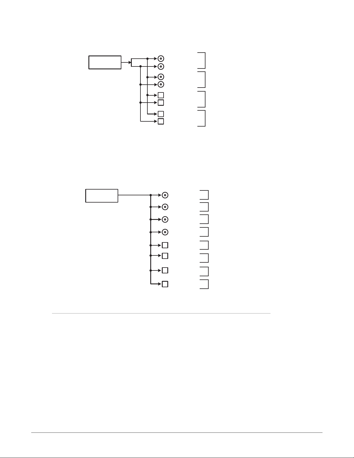
Figure 21. Single Channel Mode, Dual Link Outputs
Single Channel Mode
Dual Link Output
4K/UHD
Video Processor
SDI Out 1 BNC
(w Embedded Audio)
SDI Out 2 BNC
SDI Out 3 BNC
(w Embedded Audio)
SDI Out 4V
SDI Out 5 SFP
(w Embedded Audio)
SDI Out 6 SFP
SDI Out 7 SFP
(w Embedded Audio)
SDI Out 8 SFP
Signal Z
Signal Z
Signal Z
Signal Z
Four copies of the
same signal on all
Dual Link outputs
Because Single Channel Mode has only one Video Processor, two different video
output images cannot be created. When configured for Dual Stream output in
Single Channel Mode, the SDI-B portion of the output signal will either have no
video, or will be a copy of the SDI-A stream (Figure 22 on page 39).
Figure 22. Single Channel Mode, Dual Stream Outputs
Single Channel Mode
Dual Stream Output
4K/UHD
Video Processor
Only 1 input
signal. If the
source is Dual
Stream it will
be either SDI-A
or SDI-B.
SDI Out 1 BNC
(w Embedded Audio)
SDI Out 2 BNC
(w Embedded Audio)
SDI Out 3 BNC
(w Embedded Audio)
SDI Out 4 BNC
(w Embedded Audio)
SDI Out 5 SFP
(w Embedded Audio)
SDI Out 6 SFP
(w Embedded Audio)
SDI Out 7 SFP
(w Embedded Audio)
SDI Out 8 SFP
(w Embedded Audio)
Signal Z
Dual Stream (SDI-A)
Signal Z
Dual Stream (SDI-A)
Signal Z
Dual Stream (SDI-A)
Signal Z
Dual Stream (SDI-A)
Signal Z
Dual Stream (SDI-A)
Signal Z
Dual Stream (SDI-A)
Signal Z
Dual Stream (SDI-A)
Signal Z
Dual Stream (SDI-A)
The SDI-B portion of the
Dual Stream output will
either have no video, or
it will be a duplicate the
SDI-A stream video.
Eight copies of
the same signal
on all outputs
Local Monitoring with the FS-HDR
To support the widest range of monitoring devices, the FS-HDR provides an SDI
and an HDMI monitor output. These outputs carry the same signal. In Single
Channel mode, a 4K/UltraHD signal is automatically downconverted to 2K/HD
on the monitor output. In Four Channel, the monitor outputs can be assigned to
monitor any one of the four channels.
The SDI and HDMI outputs provide the same video dynamic range & gamut as the
monitored output. For example if the monitored output is HLG, the SDI and HDMI
monitor outputs are also HLG. However the HDMI output does not generate
a HDR Infoframe which may be required for proper viewing on HDR capable
displays.
Additional monitoring solutions are available with the FS-HDR when using
optional SFPs for additional SDI outputs. For example when delivering a 4K/
UltraHD output in Single Channel mode, the FS-HDR can be equipped with
FS-HDR Frame Synchronizer/Converter/HDR-WCG Processor v1.0r1 39 www.aja.com
Page 40

optional SFPs to provide a second quad-link 4K/UltraHD output. This output can
be used to feed an AJA Hi5-4K-Plus with an HDMI 2.0a output to connect directly
to a 4K HDMI 2.0 monitor. The Hi5-4K-Plus can be configured to transmit a HDMI
HDR Infoframe with static metadata to a HDR capable display.
Another example is equipping the FS-HDR with optional SFPs to provide four
channel monitoring when in Four Channel mode. By using the SFPs to provide an
additional four outputs, each channel will have a second SDI output that can be
fed to an AJA Hi5-Plus for HDMI 1.4 monitoring.
GPI Connections
The FS-HDR has four GPI inputs and four GPI outputs. The GPI inputs and outputs
are electrically isolated from the power and ground on the FS-HDR frame.
Electrical isolation is provided for up to four pieces of external equipment.
See "GPI Pinouts" on page 128 for information on how to wire the GPI connector
to work with external devices that you want to use to control the FS-HDR or that
you want the FS-HDR to control.
Stand Alone Tests
The stand alone tests can be performed without a computer, using the FS-HDR
front panel controls and rear connections. The following procedures assume
the FS-HDR is at factory defaults (taken from a newly opened box). If not set to
defaults, the FS-HDR may behave differently.
NOTE: FS-HDR units are configured at the factory to operate in Four Channel Mode.
First Power Up
The following workflow powers up a default FS-HDR and demonstrates some
example alarms.
Setup
• Ensure the FS-HDR is completely disconnected (all video, audio, network, and
power connector ports are empty).
Procedure
1. Connect both FS-HDR power cords to mains AC and allow time for the unit
to boot up. Observe the front panel LEDs.
• The REF LED will light red, indicating an alarm condition. By default the
FS-HDR is congured to operate genlocked to an external reference signal.
2. Press the front panel STATUS button, then turn the SELECT knob to view
various Status menus.
• The Status menu for Video Processor 1 will report No Input for IN1, the
port is disconnected), and the GEN (Genlock) parameter will report Ref
(congured for external reference) but will also report No Input.
Video Format Status screen Video Format Alarm Status screen
IN1 SDI 1 No Input
BKGD Black 1080i59
GEN Ref No Input
OUT1 1080i59
IN1 SDI 1 OK
BKGD Black OK
GEN Ref No Ref
Rate 59/29/23
FS-HDR Frame Synchronizer/Converter/HDR-WCG Processor v1.0r1 40 www.aja.com
Page 41
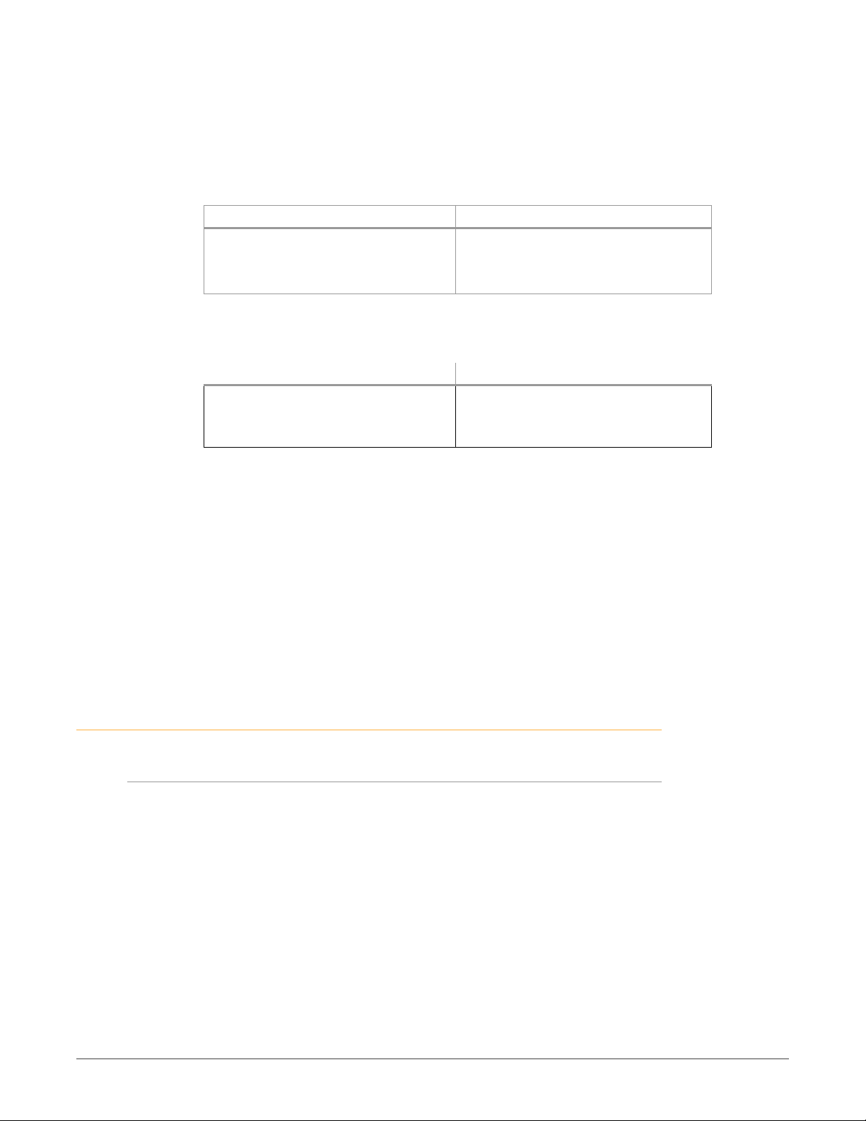
3. Connect a 1080i59.94 HD tri-level sync reference signal to one of the FS-HDR
Ref Loop BNCs, and connect a 75 ohm terminator to the other Ref BNC.
• The REF LED will light blue, indicating the FS-HDR is genlocked to reference.
• The Status menu GEN parameters will report Ref and indicate the format of
the incoming reference signal or OK.
• However, because the FS-HDR is still not receiving a compatible video input,
No Input, will be reported for IN1.
Video Format Status screen Video Format Alarm Status screen
IN1 SDI 1 No Input
BKGD Black 1080i59
GEN Ref 1080i59
OUT1 1080i59
4. Connect a 1080i59.94 SDI video source to the SDI 1 input BNC.
• The front panel will report 1080i59 and an OK status for SDI 1. This indicates
no alarm condition exists.
Video Format Status screen Video Format Alarm Status screen
IN1 SDI 1 1080i59
BKGD Black 1080i59
GEN Ref 1080i59
OUT1 1080i59
5. Disconnect one of the power cords, leaving the other attached.
• The front panel PWR LED will light red for the power supply with the
removed cord.
• The PS status will report PS1 (or 2) OFF.
6. Reconnect the power cable. The PWR LED for that power supply will light
blue and the power supply status will report OK.
This workflow confirms the FS-HDR powers up successfully and reports reference
and power supply alarms.
NOTE: FS-HDR Reference, Power Supply, and Video Format alarms can be disabled, if
desired. This will prevent the LEDs from going red, but will not affect SNMP or
front panel status displays.
IN1 SDI 1 OK
BKGD Black OK
GEN Ref OK
Rate 59/29/23
IN1 SDI 1 OK
BKGD Black OK
GEN Ref OK
OUT1 1080i59
FS-HDR Processing Examples
About FS-HDR Operating Modes
The FS-HDR has two operating modes.
• Single Channel Mode (4K/UHD) has one video processing channel capable
of 4K/UltraHD video, and supports up and down-conversion to and from HD
video.
• 4 Channel Mode (HD/SD) has four video processing channels capable of HD
video, and each channel supports independent up and down-conversion
between HD and SD video.
Both operating modes support various types of High Dynamic Range (HDR) and
Wide Color Gamut (WCG) video, and can perform conversions between them.
The appropriate FS-HDR operating mode should be selected first, because
parameter setting changes only affect the current operating mode.
To change the FS-HDR operating mode:
1. Press the CONFIG System button:
FS-HDR Frame Synchronizer/Converter/HDR-WCG Processor v1.0r1 41 www.aja.com
Page 42

2. Select 2 FS-HDR Mode
3. Select either 4K/UHD or HD/SD and press ADJUST.
NOTE: The FS-HDR must restart after its operating mode has been changed.
General FS-HDR Setup
For any FS-HDR operation the following general menu items will need to be set
correctly for your workflow. Some default FS-HDR settings may be applicable.
The following items assume front panel control. Web browser control may require
additional network configuration steps.
Select Single or Four Channel Mode (Reboot Required)
Config Menu: 2 FS-HDR Mode
• HD/SD (Four Channel mode), or 4K/UHD (Single Channel mode)
NOTE: See Step 1 on page 29 for procedure.
Select Frame Rate
Video Menu: 1 Output Frame Rate
• 59/29/23 (default), or 50/25, or 60/30/24
Select Genlock
Video Menu: 2 Genlock
• Reference (default), or Freerun, or SDI (n)
Configure Video Input
VID (n), INPUT Menu, 1 Input
• SDI (n) (default), or (n/n) Dual Link, or Quad Link
Configure Video Output
Vid (n), FORMAT Menu, 1 Output Format
• Follow Input (default), or Follow Ref, or (raster/framerate)
• Various conversion settings in related menus may also apply.
Dynamic Range Clamp (HDR Output Only)
Vid (n), FORMAT Menu, 2.2 Dynamic Range Clamp
The Dynamic Range Clamp parameter can be used to quickly preview what an
HDR signal may look like on an SDR monitor, without having to switch between
HDR and SDR modes on that monitor (which may go black during the changeover). The FS-HDR default setting is No Clamp, and this generally should be used
during production. When set to 100 Nits, the HDR signal is cleanly compressed to
SDR, allowing quick A/B comparison on an HDR display in HDR mode.
NOTE: The Dynamic Range Clamp parameter is only active when PQ BT.2020 1000 Nits
or Hybrid Log Gamma BT.2100 HDR video is being output.
Additional Settings
Other more specialized settings not discussed in the Quick Start Guide may also
apply to your workflow. Refer to the FS-HDR Installation and Operation Guide
available on the AJA website for more information.
FS-HDR Frame Synchronizer/Converter/HDR-WCG Processor v1.0r1 42 www.aja.com
Page 43
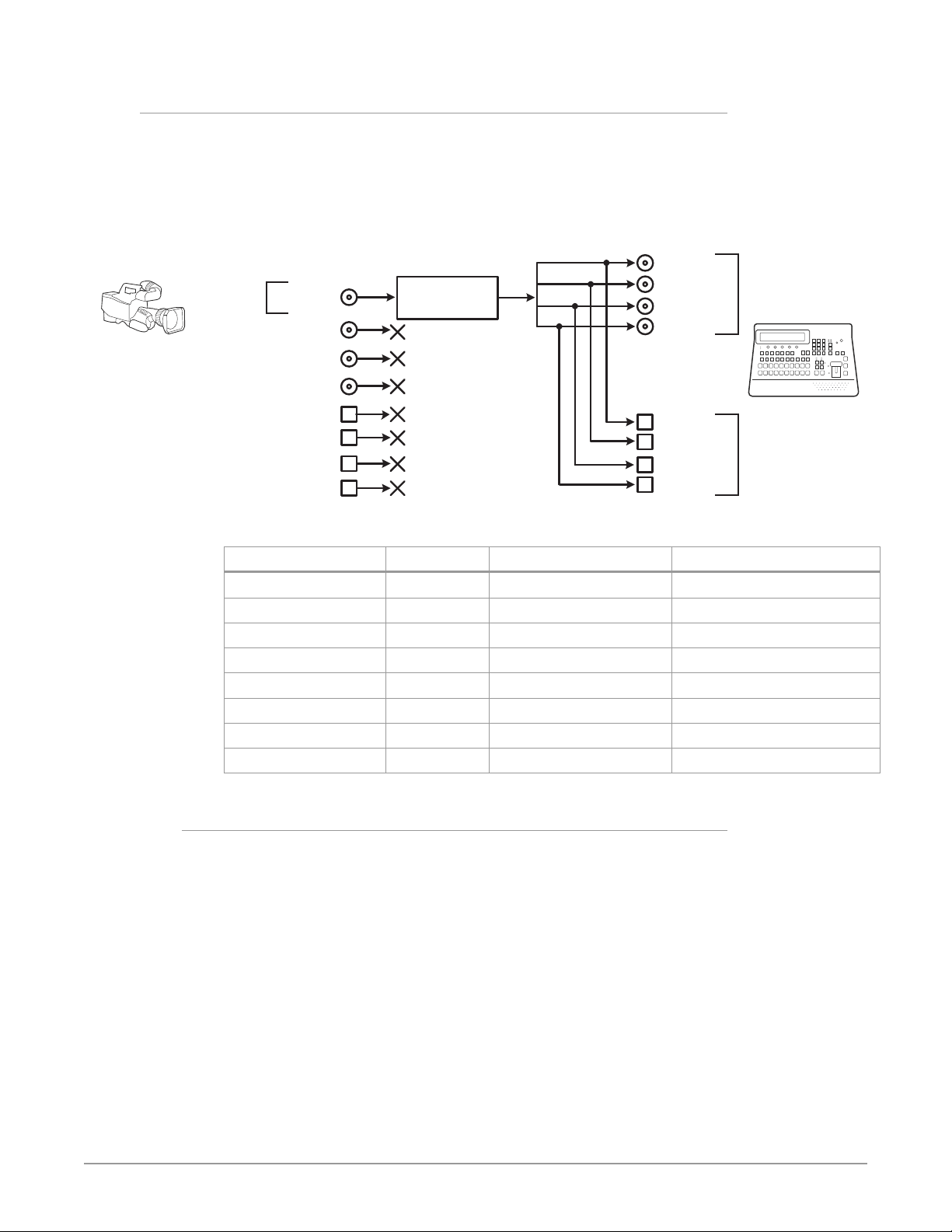
HD Video Camera to UltraHD HDR Live Production
The following workflow demonstrates feeding an HD video camera signal to an
UltraHD HDR capable video switcher through the FS-HDR for a live production. In
this example a Canon camera's HD Log 2 output is converted to UltraHD Hybrid
Log Gamma.
Figure 23. Single Channel Mode, HD Up Conversion to UltraHD HDR
Single Channel Mode
Camera HD Up-Conversion to UltraHD with HDR
Camera Signal
1920 x1080i
59.94 (SDR)
SDI In 1 BNC
SDI In 2 BNC
SDI In 3 BNC
SDI In 4 BNC
4K/UHD
Video Processor with
Colorfront Engine
SDI Out 1 BNC
SDI Out 2 BNC
SDI Out 3 BNC
SDI Out 4 BNC
Signal to Video Switcher
Up-Converted to
Quad Link UltraHD
3840x2160p 59.94 (HLG)
SDI In 5 SFP
SDI In 6 SFP
SDI In 7 SFP
SDI In 8 SFP
Table 2. Menu Settings for Single Channel Mode, Up Conversion
Channel Select Button Video Button Menu Name Setting
VID1 INPUT 1 Input SDI1
VID1 INPUT 2.1 Dynamic Range&Gamut Canon Log 2 (match to camera)
VID1 FORMAT 1 Output Format UHD2160p5994
VID1 FORMAT 2.1 Dynamic Range&Gamut Hybrid Log Gamma BT.2100
VID1 FORMAT 2.2 Dynamic Range Clamp No Clamp (default)
VID1 FORMAT 3.0 Link Cfg SDI1-4 Quad Link LvlA
VID1 FORMAT 4.0 Link Cfg SDI5-8 Quad Link LvlA
VID1 FORMAT 5.0 Output Image Mapping Quadrant or 2SI (as required)
Setup
• Ensure the FS-HDR is receiving a valid reference signal. Connect a 1080i59.94
HD tri-level sync signal to one of the Ref Loop BNC connectors, and terminate
the other Ref Loop BNC connector.
• Congure the camera (for example, SDI 1080i59.94 Canon Log 2)
• Connect the camera's SDI output connector to the SDI1 input on the rear of
the FS-HDR. Once connected the FS-HDR front panel VID IN LED will light.
• Connect the four FS-HDR SDI1-4 video output BNC connectors to a UltraHD
video production switcher that supports Hybrid Log Gamma.
• View the FS-HDR SDI output signal on a compatible HDR display.
SDI Out 5 SFP
SDI Out 6 SFP
SDI Out 7 SFP
SDI Out 8 SFP
Signal Up-Converted to
Quad Link UltraHD
3840x2160p 59.94 (HLG)
(Requires optional SFP
modules)
FS-HDR Frame Synchronizer/Converter/HDR-WCG Processor v1.0r1 43 www.aja.com
Page 44

Procedure
System Configuration
1. If the FS-HDR is not already in Single Channel Mode, press the CONFIG
System button:
• Select 2 FS-HDR Mode, select 4K/UHD and press the ADJUST knob. Wait for
the FS-HDR to reboot (not longer than 90 seconds).
2. Press the VIDEO System button.
• Select 1 Output Frame Rate, and adjust to 59/29/23.
• Select 2 Genlock Source, and adjust to Reference.
Video Processor Setup
3. Press the VID1 Channel Select button.
4. Press the INPUT Video button.
• Select 1 Input, and adjust to SDI 1.
• Select 2.1 Dynamic Range&Gamut, and match to the camera, in this example
Canon Log 2.
5. Press the FORMAT Video button.
• Select 1 Output Format, and adjust to UHD2160p5994.
• Select 2.1 Dynamic Range&Gamut and select Hybrid Log Gamma BT.2100.
• Select 2.2 Dynamic Range Clamp and ensure No Clamp (default) is selected.
NOTE: Setting Dynamic Range Clamp to 100 Nits allows you to quickly A/B preview on a
connected HDR monitor how the video may appear on an SDR display.
• Select 3.0 Link Cfg SDI1-4 and adjust to QuadLnk LvlA.
• Select 5.0 Output Mapping and select either Quadrant (default) or 2SI as
required for your production.
6. If you have optional SFP output modules installed, you can select FORMAT
4.0 Link Cfg SDI5-8 and adjust to QuadLnk LvlA for an additional copy of that
converted signal.
The video switcher should now be able to accept the up-converted UltraHD HLG
camera signal.
4K HDR to HD HDR Down and Cross-Conversion
The following workflow demonstrates down-converting a Quad Link 4K input to
HD, and simultaneously cross-converting the HDR/WCG format, from PQ (HDR-
10) to HLG. The 4096x2160 input will be cropped to 3840x2160 and then down
converted.
FS-HDR Frame Synchronizer/Converter/HDR-WCG Processor v1.0r1 44 www.aja.com
Page 45
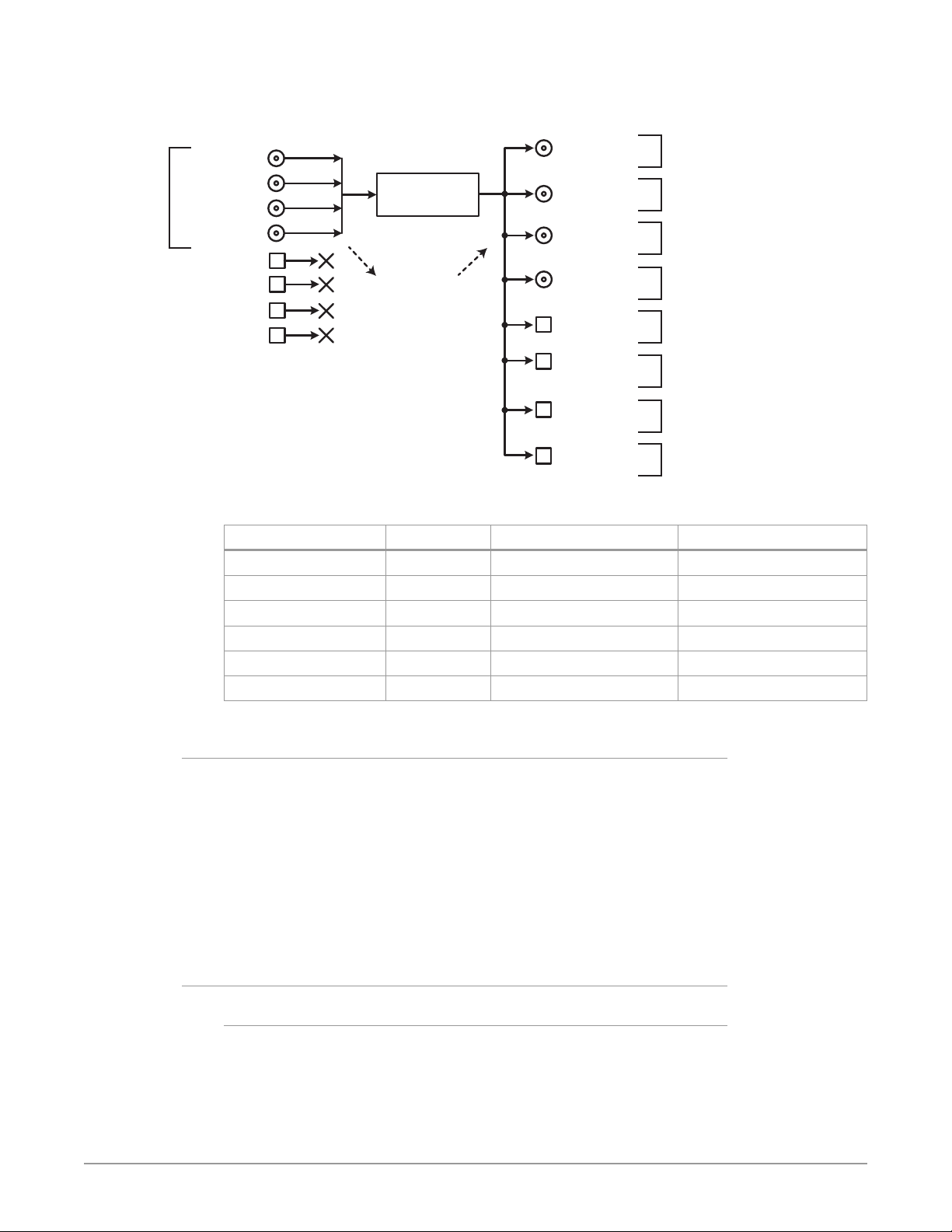
Figure 24. Single Channel Mode, Down and HDR Cross-Conversion
Single Channel Mode
4K Down-Conversion and HDR Cross-Conversion
SDI In 1 BNC
(w Embedded Audio)
SDI In 2 BNC
Quad Link 4K
4096x2160p
59.94 PQ
(w Embedded Audio)
SDI In 3 BNC
(w Embedded Audio)
SDI In 4 BNC
(w Embedded Audio)
SDI In 5 SFP
SDI In 6 SFP
SDI In 7 SFP
SDI In 8 SFP
4K/UHD
Video Processor with
Colorfront Engine
Incoming embedded
audio is disembedded,
sent to the Audio Processor,
and can be routed
to the output.
SDI Out 1 BNC
(w Embedded Audio)
SDI Out 2 BNC
(w Embedded Audio)
SDI Out 3 BNC
(w Embedded Audio)
SDI Out 4 BNC
(w Embedded Audio)
SDI Out 5 SFP
(w Embedded Audio)
SDI Out 6 SFP
(w Embedded Audio)
SDI Out 7 SFP
(w Embedded Audio)
Down Convert to
1920 x1080p 59.94 HLG
Down Convert to
1920 x1080p 59.94 HLG
Down Convert to
1920 x1080p 59.94 HLG
Down Convert to
1920 x1080p 59.94 HLG
Down Convert to
1920 x1080p 59.94 HLG
Down Convert to
1920 x1080p 59.94 HLG
Down Convert to
1920 x1080p 59.94 HLG
Eight copies of
the same signal
on all outputs
Outputs 5-8
require optional
SFP modules
SDI Out 8 SFP
(w Embedded Audio)
Table 3. Menu Settings for Single Channel Mode, Down and Cross Conversion
Channel Select Button Video Button Menu Name Setting
VID1 INPUT 1 Input 1-4 QuadLink
VID1 INPUT 2.1 Dynamic Range&Gamut PQ BT.2020 1000Nits
VID1 FORMAT 1 Output Format 1080p5994
VID1 FORMAT 2.1 Dynamic Range&Gamut Hybrid Log Gamma BT.2100
VID1 FORMAT 3.0 Link Cfg SDI1-4 Sngl Link LvlA
VID1 FORMAT 4.0 Link Cfg SDI5-8 Sngl Link LvlA
Setup
• Ensure the FS-HDR is receiving a valid reference signal. Connect a 1080p 59.94
HD tri-level sync signal to one of the Ref Loop BNC connectors, and terminate
the other Ref Loop BNC connector.
• Connect a Quad Link 4K 59.94 signal to the FS-HDR SDI 1, 2, 3, and 4 video
input BNC connectors.
• Connect any one of the FS-HDR SDI BNC output connectors to a compatible
HDR video monitor.
• Ensure the FS-HDR Vid (n) FORMAT 2.2 Dynamic Range Clamp parameter is set
to No Clamp (default).
Down Convert to
1920 x1080p 59.94 HLG
Procedure
System Configuration
1. If the FS-HDR is not already in Single Channel Mode, press the CONFIG
System button:
• Select 2 FS-HDR Mode, select 4K/UHD and press the ADJUST knob. Wait for
the FS-HDR to reboot (not longer than 90 seconds).
FS-HDR Frame Synchronizer/Converter/HDR-WCG Processor v1.0r1 45 www.aja.com
Page 46
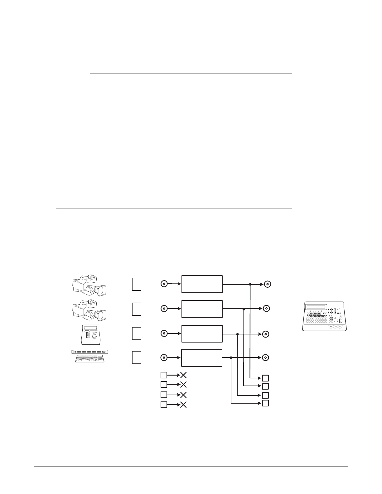
Four Channel Mode
2. Press the VIDEO System button
• Select 1 Output Frame Rate, and adjust to 59/29/23.
• Select 2 Genlock Source, and adjust to Reference.
Video Processor Setup
3. Press the VID1 Channel Select button
4. Press the INPUT Video button
• Select 1 Input, and adjust to 1-4 QuadLnk.
• Select 2.1 Dynamic Range&Gamut, and select PQ BT.2020 1000Nits.
5. Press the FORMAT Video button.
• Select 1 Output Format, and adjust to 108 0p5994.
• Select 2.1 Dynamic Range&Gamut, and select Hybrid Log Gamma BT.2100.
• Select 3.0 Link Cfg SDI1-4 and adjust to Sngl Lnk LvlA.
6. If you have optional SFP output modules installed, you can select FORMAT
4.0 Link Cfg SDI5-8 and adjust to Sngl Lnk LvlA for an additional copy of that
converted signal.
The down-converted HD signal should now be present on the connected HDR
video monitor.
Multiple Legacy Device SDR To HDR Live Conversion
The following workflow demonstrates simultaneously converting multiple legacy
device SD and HD signals for an HD HDR production. In this example, signals
from two legacy SDR HD cameras, a legacy SD Video Replay system, and a legacy
SD Character Generator are up-converted or transformed to HLG for a live HDR
production. Four Channel mode operation is required.
Figure 25. Four Channel Mode Example, Four Conversions
Multiple Device Conversion to HDR
Camera 1
1920x1080i
59.94 (SDR)
Camera 2
1920x1080i
59.94 (SDR)
Video Replay
525i (SDR)
Character
Generator
525i (SDR)
SDI In 1 BNC
SDI In 2 BNC
SDI In 3 BNC
SDI In 4 BNC
SDI In 5 SFP
SDI In 6 SFP
SDI In 7 SFP
SDI In 8 SFP
HD/SD
Video Processor with
Colorfront Engine
HD/SD
Video Processor with
Colorfront Engine
HD/SD
Video Processor with
Colorfront Engine
HD/SD
Video Processor with
Colorfront Engine
SDI Out 1 BNC
Camera 1
1920x1080p
59.94 HLG
SDI Out 2 BNC
Camera 2
1920x1080p
59.94 HLG
SDI Out 3 BNC
Video Replay
1920x1080p
59.94 HLG
SDI Out 4 BNC
Character Generator
1920x1080p
59.94 HLG
SDI Out 5 SFP
SDI Out 6 SFP
SDI Out 7 SFP
SDI Out 8 SFP
Output Signals to
HDR Video Switcher
One copy of each
converted signal
on each SFP output
(requires optional
SFP modules)
FS-HDR Frame Synchronizer/Converter/HDR-WCG Processor v1.0r1 46 www.aja.com
Page 47

Table 4. Menu Settings for Four Channel Mode Example, Two Conversions
Channel Select Button Video Button Menu Name Setting
VID1 INPUT 1 Input SDI1
VID1 INPUT 2.1 Dynamic Range&Gamut SDR BT.709 100 Nits
VID1 INPUT 2.2 SDR Highlights If necessary, select best image from:
Standard (default), Soft 1-3, Bright
VID1 FORMAT 1 Output Format 1080p5994
VID1 FORMAT 2.1 Dynamic Range&Gamut Hybrid Log Gamma BT.2100
VID1 FORMAT 3.0 Link Cfg SDI1 Sngl Link LvlA
VID1 FORMAT 4.0 Link Cfg SDI5 Sngl Link LvlA
VID2 INPUT 1 Input SDI2
VID2 INPUT 2.1 Dynamic Range&Gamut SDR BT.709 100 Nits
VID2 INPUT 2.2 SDR Highlights If necessary, select best image from:
Standard (default), Soft 1-3, Bright
VID2 FORMAT 1 Output Format 1080p5994
VID2 FORMAT 2.1 Dynamic Range&Gamut Hybrid Log Gamma BT.2100
VID2 FORMAT 3.0 Link Cfg SDI2 Sngl Link LvlA
VID2 FORMAT 4.0 Link Cfg SDI6 Sngl Link LvlA
VID3 INPUT 1 Input SDI3
VID3 INPUT 2.1 Dynamic Range&Gamut SDR BT.709 100 Nits
VID3 INPUT 2.2 SDR Highlights If necessary, select best image from:
Standard (default), Soft 1-3, Bright
VID3 FORMAT 1 Output Format 1080p5994
VID3 FORMAT 2.1 Dynamic Range&Gamut Hybrid Log Gamma BT.2100
VID3 FORMAT 3.0 Link Cfg SDI3 Sngl Link LvlA
VID3 FORMAT 4.0 Link Cfg SDI7 Sngl Link LvlA
VID4 INPUT 1 Input SDI4
VID4 INPUT 2.1 Dynamic Range&Gamut SDR BT.709 100 Nits
VID4 INPUT 2.2 SDR Highlights If necessary, select best image from:
Standard (default), Soft 1-3, Bright
VID4 FORMAT 1 Output Format 1080p5994
VID4 FORMAT 2.1 Dynamic Range&Gamut Hybrid Log Gamma BT.2100
VID4 FORMAT 3.0 Link Cfg SDI4 Sngl Link LvlA
VID4 FORMAT 4.0 Link Cfg SDI8 Sngl Link LvlA
Setup
• Ensure the FS-HDR is receiving a valid reference signal. Connect a 1080i59.94
HD tri-level sync signal to one of the Ref Loop BNC connectors, and terminate
the other Ref Loop BNC connector.
• Congure the source devices to the desired settings and connect them to SDI1
through SDI 4 BNC inputs on the rear of the FS-HDR. Once connected the LED
below the VID1 button on the FS-HDR front panel will light.
• Connect the FS-HDR SDI1 through SDI4 BNC output connectors to a HDR
compatible video switcher.
• Ensure the FS-HDR Vid (n) FORMAT 2.2 Dynamic Range Clamp parameter is set
to No Clamp (default).
FS-HDR Frame Synchronizer/Converter/HDR-WCG Processor v1.0r1 47 www.aja.com
Page 48

• View the FS-HDR SDI output signal on a compatible HDR display.
Procedure
System Configuration
1. If the FS-HDR is not already in Four Channel Mode, press the CONFIG System
button:
• Select 2 FS-HDR Mode, select HD/SD and press the ADJUST knob. Wait for the
FS-HDR to reboot (not longer than 90 seconds).
2. Press the VIDEO System button.
• Select 1 Output Frame Rate, and adjust to 59/29/23.
• Select 2 Genlock Source, and adjust to Reference.
Video Processor 1 Setup
3. Press the VID1 Channel Select button
4. Press the INPUT Video button
• Select 1 Input, and adjust to SDI1.
• Select 2.1 Dynamic Range&Gamut, and select SDR BT.709 100 Nits.
5. Press the FORMAT Video button.
• Select 1 Output Format, and adjust to 108 0p5994.
• Select 2.1 Dynamic Range&Gamut, and select Hybrid Log Gamma BT.2100.
6. Press the INPUT Video button
• Select 2.2 SDR Highlights and select for best image from: Standard (default),
Soft 1-3, or Bright.
NOTE: The SDR Highlights parameter is only active when transforming from SDR to
HDR. Source SDR video dynamic range compression can vary, and only be visible
when expanded to HDR. This parameter offers five different presets that can be
used to try to match the source material. For lesser quality SDR video that exhibits
substantial clipping, a less aggressive expansion is a better choice. The Soft 1 to 3
settings are progressively less aggressive.
7. If you have optional SFP output modules installed, you can select FORM AT
3.0 Link Cfg SDI5 and adjust to Sngl Lnk LvlA for an additional copy of that
converted signal.
Video Processor 2, 3, and 4 Setup
8. Press the VID2, 3 or 4 Channel Select button.
9. Repeat the Video Processor 1 setup steps described above, substituting 2/6,
3/7, and 4/8 as appropriate.
The video switcher should now be able to accept all the converted to HLG signals.
Multiple Simultaneous HDR and SDR Distribution
The following workflow demonstrates simultaneously distributing HDR and SDR
content. In this example, the FS-HDR converts one HDR input to a different HDR
format output and also converts it to an SDR output. Simultaneously the FS-HDR
also converts two other signals, one from a BNC input, and the other from an SFP
module input. Four Channel mode operation is required.
FS-HDR Frame Synchronizer/Converter/HDR-WCG Processor v1.0r1 48 www.aja.com
Page 49
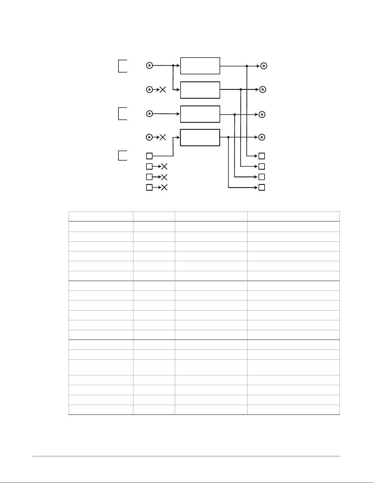
Figure 26. Four Channel Mode Example, Four Conversions of Three Sources
Four Channel Mode
Simultaneous HDR and SDR Distribution
Source A
1920x1080p
59.94 PQ
SDI In 1 BNC
HD/SD
Video Processor with
Colorfront Engine
SDI Out 1 BNC
Converted Source A
1920x1080p 59.94 HLG
SDI Out 2 BNC
Converted Source A
1920x1080i 59.94 (SDR)
SDI Out 3 BNC
Converted Source B
1280x720p 59.94 HLG
SDI Out 4 BNC
Converted Source C
1280x720p 59.94 HLG
SDI Out 5 SFP
SDI Out 6 SFP
SDI Out 7 SFP
SDI Out 8 SFP
One copy of each
converted signal
on each SFP output
(requires optional
SFP modules)
Source B
525i (SDR)
Source C
1920x1080i
59.94 (SDR)
(requires optional
SFP module)
SDI In 2 BNC
SDI In 3 BNC
SDI In 4 BNC
SDI In 5 SFP
SDI In 6 SFP
SDI In 7 SFP
SDI In 8 SFP
HD/SD
Video Processor with
Colorfront Engine
HD/SD
Video Processor with
Colorfront Engine
HD/SD
Video Processor with
Colorfront Engine
Table 5. Menu Settings for Four Conversions of Three Sources
Channel Select Button Video Button Menu Name Setting
VID1 INPUT 1 Input SDI1
VID1 INPUT 2.1 Dynamic Range&Gamut PQ BT.2020 1000 Nits
VID1 FORMAT 1 Output Format 1080p5994
VID1 FORMAT 2.1 Dynamic Range&Gamut Hybrid Log Gamma BT.2100
VID1 FORMAT 3.0 Link Cfg SDI1 Sngl Link LvlA
VID1 FORMAT 4.0 Link Cfg SDI5 Sngl Link LvlA
VID2 INPUT 1 Input SDI1
VID2 INPUT 2.1 Dynamic Range&Gamut PQ BT.2020 1000 Nits
VID2 FORMAT 1 Output Format 1080i5994
VID2 FORMAT 2.1 Dynamic Range&Gamut SDR BT.709 100 Nits
VID2 FORMAT 3.0 Link Cfg SDI2 Sngl Link LvlA
VID2 FORMAT 4.0 Link Cfg SDI6 Sngl Link LvlA
VID3 INPUT 1 Input SDI3
VID3 INPUT 2.1 Dynamic Range&Gamut SDR BT.709 100 Nits
VID3 INPUT 2.2 SDR Highlights If necessary, select best image from:
Standard (default), Soft 1-3, Bright
VID3 FORMAT 1 Output Format 720p5994
VID3 FORMAT 2.1 Dynamic Range&Gamut Hybrid Log Gamma BT.2100
VID3 FORMAT 3.0 Link Cfg SDI3 Sngl Link LvlA
VID3 FORMAT 4.0 Link Cfg SDI7 Sngl Link LvlA
FS-HDR Frame Synchronizer/Converter/HDR-WCG Processor v1.0r1 49 www.aja.com
Page 50
Channel Select Button Video Button Menu Name Setting
VID4 INPUT 1 Input SDI5
VID4 INPUT 2.1 Dynamic Range&Gamut SDR BT.709 100 Nits
VID4 INPUT 2.2 SDR Highlights If necessary, select best image from:
Standard, Soft 1-3, Bright
VID4 FORMAT 1 Output Format 720p5994
VID4 FORMAT 2.1 Dynamic Range&Gamut Hybrid Log Gamma BT.2100
VID4 FORMAT 3.0 Link Cfg SDI4 Sngl Link LvlA
VID4 FORMAT 4.0 Link Cfg SDI8 Sngl Link LvlA
Setup
• Ensure the FS-HDR is receiving a valid reference signal. Connect a 1080i59.94
HD tri-level sync signal to one of the Ref Loop BNC connectors, and terminate
the other Ref Loop BNC connector.
• Connect sources A and B to the FS-HDR SDI 1 and SDI 3 Input BNCs.
• Install an optional SFP module into the FS-HDR SDI 5 Input cage and connect
the source cable.
• Connect the FS-HDR SDI outputs to the downstream devices.
• Ensure the FS-HDR Vid (n) FORMAT 2.2 Dynamic Range Clamp parameter is set
to No Clamp (default).
• View the FS-HDR SDI output signals on a compatible HDR or SDR display.
Procedure
System Configuration
1. If the FS-HDR is not already in Four Channel Mode, press the CONFIG System
button:
• Select 2 FS-HDR Mode, select HD/SD and press the ADJUST knob. Wait for the
FS-HDR to reboot (not longer than 90 seconds).
2. Press the VIDEO System button
• Select 1 Output Frame Rate, and adjust to 59/29/23.
• Select 2 Genlock Source, and adjust to Reference.
Video Processor 1 Setup
3. Press the VID1 Channel Select button.
4. Press the INPUT Video button.
• Select 1 Input, and adjust to SDI1.
• Select 2.1 Dynamic Range&Gamut, and select PQ BT.2020 1000 Nits.
5. Press the FORMAT Video button.
• Select 1 Output Format, and adjust to 108 0p5994.
• Select 2.1 Dynamic Range&Gamut, and select Hybrid Log Gamma BT.2100s
6. If you have optional SFP output modules installed, you can select FORMAT
3.0 Link Cfg SDI5 and adjust to Sngl Lnk LvlA for an additional copy of that
converted signal.
Video Processor 2 Setup
7. Press the VID2 Channel Select button.
FS-HDR Frame Synchronizer/Converter/HDR-WCG Processor v1.0r1 50 www.aja.com
Page 51

8. Press the INPUT Video button.
• Select 1 Input, and adjust to SDI1 (same input as Video Processor 1).
• Select 2.1 Dynamic Range&Gamut, and select PQ BT.2020 1000 Nits.
9. Press the FORM AT Video button.
• Select 1 Output Format, and adjust to 108 0p5994
• Select 2.1 Dynamic Range&Gamut, and select SDR BT.709 100 Nits.
10. If you have optional SFP output modules installed, you can select FORMAT
3.0 Link Cfg SDI6 and adjust to Sngl Lnk LvlA for an additional copy of that
converted signal.
Video Processor 3 Setup
11. Press the VID3 Channel Select button.
12. Press the INPUT Video button.
• Select 1 Input, and adjust to SDI3.
• Select 2.1 Dynamic Range&Gamut, and select SDR BT.709 100 Nits.
13. Press the FO RMAT Video button.
• Select 1 Output Format, and adjust to 720p5994.
• Select 2.1 Dynamic Range&Gamut, and select Hybrid Log Gamma BT.2100.
14. Press the INPUT Video button
• Select 2.2 SDR Highlights and select for best image from: Standard (default),
Soft 1-3, or Bright.
15. If you have optional SFP output modules installed, you can select FORM AT
3.0 Link Cfg SDI7 and adjust to Sngl Lnk LvlA for an additional copy of that
converted signal.
Video Processor 4 Setup
16. Press the VID4 Channel Select button.
17. Press the INPUT Video button.
• Select 1 Input, and adjust to SDI5.
• Select 2.1 Dynamic Range&Gamut, and select SDR BT.709 100 Nits.
18. Press the FORM AT Video button.
• Select 1 Output Format, and adjust to 720p5994.
• Select 2.1 Dynamic Range&Gamut, and select Hybrid Log Gamma BT.2100.
19. Press the INPUT Video button
• Select 2.2 SDR Highlights and select for best image from: Standard (default),
Soft 1-3, or Bright.
20. If you have optional SFP output modules installed, you can select FO RMAT
3.0 Link Cfg SDI8 and adjust to Sngl Lnk LvlA for an additional copy of that
converted signal.
Dual Stream Signal Separation
The following workflow demonstrates separating two Dual Stream inputs and
routing the signals to different outputs.
NOTE: In the following example, U, V, W, X, Y, and Z represent different complete signals,
which may be carried on one or more connectors.
FS-HDR Frame Synchronizer/Converter/HDR-WCG Processor v1.0r1 51 www.aja.com
Page 52

Four Channel Mode
Dual Stream
Signal U
Dual Stream
Signal V
SDI In 1 BNC
(w Embedded Audio)
SDI In 2 BNC
SDI In 3 BNC
SDI In 4 BNC
SDI In 5 SFP
(w Embedded Audio)
SDI In 6 SFP
SDI In 7 SFP
SDI In 8 SFP
Figure 27. Four Channel Mode, Dual Stream Inputs Separated
Dual Stream Inputs Separated
SDI-A
SDI-B
SDI-A
SDI-B
All incoming embedded
audio is disembedded and
sent to Audio Processor
HD/SD
Video Processor 1
HD/SD
Video Processor 2
HD/SD
Video Processor 3
HD/SD
Video Processor 4
SDI Out 1 BNC
(w Embedded Audio)
SDI Out 2 BNC
(w Embedded Audio)
SDI Out 3 BNC
(w Embedded Audio)
SDI Out 4 BNC
(w Embedded Audio)
SDI Out 5 SFP
(w Embedded Audio)
SDI Out 6 SFP
(w Embedded Audio)
Signal W
(SDI-A only)
Signal X
(SDI-B only)
Signal Y
(SDI-B only)
Signal W
(SDI-A only)
Signal X
(SDI-B only)
Signal Z
(SDI-A only)
Dual Stream input
videos separated and
routed to dierent
connectors, with each
signal duplicated once
SDI Out 7 SFP
(w Embedded Audio)
SDI Out 8
(w Embedded Audio)
Signal Y
(SDI-B only)
Signal Z
(SDI-A only)
Table 6. FS-HDR Menu Settings for Figure 27.
System Button Menu Name Setting
VIDEO 4.1 SDI1 3G Detect Dual Stream
VIDEO 4.2 SDI2 Input Protect Dual Stream
Channel Select Button Video Button Menu Name Setting
VID1 INPUT 1 Input SDI1
VID1 FORMAT 1 Output Format Follow Input
VID1 FORMAT 2.0 Link Cfg SDI1 Sngl Link LvlA
VID2 INPUT 1 Input SDI2
VID2 FORMAT 1 Output Format Follow Input
VID2 FORMAT 2.0 Link Cfg SDI1 Sngl Link LvlA
VID3 INPUT 1 Input SDI6
VID3 FORMAT 1 Output Format Follow Input
VID3 FORMAT 2.0 Link Cfg SDI1 Sngl Link LvlA
VID4 INPUT 1 Input SDI5
VID4 FORMAT 1 Output Format Follow Input
VID4 FORMAT 2.0 Link Cfg SDI1 Sngl Link LvlA
FS-HDR Frame Synchronizer/Converter/HDR-WCG Processor v1.0r1 52 www.aja.com
Page 53

Chapter 4 – Display Menus
Overview
The FS-HDR is generally controlled using two different methods: (1) direct control
using the front panel buttons, knobs, and display menus, (2) remote control using
a web browser. This chapter describes the first, using the front panel controls,
which is the most direct way to configure and use an FS-HDR. The other method,
using a computer, is described in the next chapter. A third method of FS-HDR
control, using external GPI contacts, is described in various locations in this
manual.
FS-HDR Modes, System Parameters, and Video Parameters
The FS-HDR also operates in two distinct modes, either Four Channel Mode or
Single Channel Mode. Menu parameters settings made in one mode may or may
not affect the operation of FS-HDR when it is set to the other mode. For example,
in Single Channel Mode, setting Output Image Mapping to 2SI will not affect
operations in Four Channel Mode, because that parameter only affects 4K or
UltraHD formats that are not available in Four Channel mode. However, changing
the IP Address Type (DHCP, Static) will affect FS-HDR operation in both modes
regardless of the mode in which that parameter was adjusted.
In general, settings made for FS-HDR system operation, like IP address, Output
Frame Rate, Genlock, etc. affect operation in both Four Channel and Single
Channel mode. These front panel menu settings are accessed via the three
System buttons (VIDEO, CONFIG, and AUDIO).
The Channel Select AES menus (and associated LEVEL and DELAY menu
parameters for AES and MADI), also affect the FS-HDR in both operating modes.
Separate MAP parameters for audio routing, however, are saved for each Video
Processor, so changing mapping in one operating mode will not affect mapping
in the other mode.
The Channel Select EMBED menus provide LEVEL, DELAY, and MAP menu
parameters for embedded SDI audio. Because both operating modes use the
same SDI inputs, adjustment to these parameters affects both modes.
Video parameter settings in the Channel Select VID1-4 menus (and associated
VIDEO submenus) apply to only the current FS-HDR operating mode. In Four
Channel Mode, each VID channel accesses separate settings for only that channel,
allowing four different conversions to take place simultaneously. In Single
Channel Mode, only one set of video parameters exists that apply to that single
channel. Changing video parameters in Four Channel Mode will not affect any
video settings stored in Single Channel Mode.
NOTE: One exception is in the REMOTE Menu Group. The Remote Control setting (Local,
Remote) affects both Four Channel and Single Channel mode, but separate sets
of GPI In and GPI Out settings exist for each operating mode. Single Channel
Mode has only one set. Separate GPI inputs and outputs are needed for the
different functionality available in these two modes.
FS-HDR Frame Synchronizer/Converter/HDR-WCG Processor v1.0r1 53 www.aja.com
Page 54
Presets and FS-HDR Operating Mode
Independent sets of FS-HDR Presets exist for Four Channel and Single Channel
mode. Forty presets are available in each mode, each can be given a different
name, and storing or recalling a preset in Four Channel mode will not affect
FS-HDR operation in Single Channel mode.
Caution! In Four Channel Mode, each Preset saves all the settings for all four
channels. Storing and recalling a Preset will aect all the settings for all four
channels in that mode. Care must be taken to establish a policy for the use of
FS-HDR Presets, especially if the FS-HDR is operated in Four Channel mode and
the dierent channels have dierent users.
Parameter Menus
The FS-HDR display presents five major types of menu pages:
• Status pages—present status information that cannot be changed.
• Simple parameter menus—contain a parameter number and name on line 1
and its current value setting on line 2. The line 2 value can be changed using
SELECT and ADJUST. Example: Output Format.
• “Take action” parameter menus—contain a parameter number and name
on line 1, and the value to “take” on line 2. A “take” prompt may appear on
line 3. The line 2 value can be changed using SELECT and ADJUST, and the
take or switch to the new value occurs when you press ADJUST momentarily.
Examples: Preset Save/Recall.
• Multiple eld parameter menus—contain a parameter number and name
on line 1 and its current value setting on line 2, consisting of multiple letter
or number elds that must each be set individually. The line 2 elds can be
changed using SELECT and ADJUST. Example: IP Address.
• Hidden parameter menus—a “parent” menu exists that, when that parent
parameter is turned on, can display “child” menus of related parameters.
When the Hidden Menus parameter is set to Hide Inactive, these child menus
are hidden when the parent parameter is o. Some menu names contain a
decimal (dot) number and zero, which indicates there are a group of related
parameters. Example: 1.0 ProcAmp is the parent menu of the 1.1 through 1.4
child menus.
NOTE: In this chapter, menus unique to an FS-HDR operating mode will be indicated as
(4Ch only) or (SingleCh only). Other menus are identical in both Four Channel and
Single Channel modes.
STATUS Menu Group
The Status Menu Group contains a series of Status display pages that you can
scroll using the SELECT knob. The various Status pages are actually just displays,
not menus, since they don’t include menu numbers or editable values. The
ADJUST knob doesn’t affect the Status Menu Group display pages.
System Status
This menu shows the FS-HDR’s System Name, IP address and mask, and version
number.
System Name
IP addr value
IP Mask value
Version value
FS-HDR Frame Synchronizer/Converter/HDR-WCG Processor v1.0r1 54 www.aja.com
Displays the System Name as set in Cong menu 1.
Shows the IP address.
Shows the IP mask.
Shows the software version number.
Page 55

NOTE: The STATUS menu always shows the FS-HDR’s current Ethernet settings. The
Vid 1/2 I/O
(4Ch only) This menu shows the current primary video settings for Video
Processors 1 and 2.
parameters shown on the CONFIG Menu Group IP configuration menu may not
display the values the unit is currently using.
IN1 Input Source Format
OUT1 Output Source Format
IN2 Input Source Format
OUT2 Output Source Format
Vid 3/4 I/O
(4Ch only) Same as Vid 1/2 I/O status menu, except for Video Processors 3 and 4.
Vid I/O
(SingleCh only) This menu shows the current primary video settings for Video
Processor.
IN Input Source(s) Format
GEN Genlock Source Status
OUT Format AudIn
Vid CC Status
Vid 1 Format
(4Ch only) This menu shows the current primary video settings for Video
Processor 1.
Selected (physical) video 1 input & detected format.
Selected video output 1 format & selected audio input
used on output.
Selected (physical) video 2 input & detected format.
Selected video output 2 format & selected audio input
used on output.
Selected (physical) video 1-4 inputs & detected format.
Selected Genlock source and format.
Selected video output format & selected audio input
used on output
Closed Caption status
IN1 Input Source Format
BKGD Backgd Source
GEN Genlock Source Format
OUT1 Format
Selected video input source and format.
Selected Background video source.
Selected Genlock source and format.
Selected video output format.
Vid 2-4 Format
(4Ch only) Same as Vid 1 Format menu, except for Video Processors 2-4.
Vid 1 Alarm
(4Ch only) This menu shows the Video Processor 1 alarm status. Absence of alarm
shows as OK. If selections are incompatible, the status of the affected signal
shows Incompat.
IN1 Input Source Status
BKGD Backgd Source Status
GEN Genlock Source Status
Rate Status
Video input source alarm status.
Selected Background video source alarm status.
Selected Genlock source alarm status.
System Output Frame Rate (59/29/23.98, 50/25, 60/30/24)
Vid 2-4 Alarm
(4Ch only) Same as Vid 1 Alarm menu, except for Video Processors 2-4.
FS-HDR Frame Synchronizer/Converter/HDR-WCG Processor v1.0r1 55 www.aja.com
Page 56
Vid Alarm
(Single Ch only) This menu shows the Video Processor 1 alarm status. Absence of
alarm shows as OK. If selections are incompatible, the status of the affected signal
shows Incompat.
IN Input Source(s) Status
GEN Genlock Source Status
Rate Status
SDI Input
This menu shows the status of all eight SDI inputs.
SDI1 Status SDI5 Status
SDI2 Status SDI6 Status
SDI3 Status SDI7 Status
SDI4 Status SDI8 Status
Monitor Output
This menu shows the status of the monitor outputs (BNC and HDMI).
Monit Status
Fmt Status
Crop Status
AES Input
This menu shows the status of all eight AES channel pair inputs. Each can carry a
stereo digital audio signal.
Video input source alarm status.
Selected Genlock source alarm status.
System Output Frame Rate (59/29/23.98, 50/25, 60/30/24)
Statuses for SDI inputs 1-8: (Format, No Input, No SFP)
Output selected for monitoring (Vid1-4 Out)
Output format.
Crop status (O, On).
AES1 Status AES5 Status
AES2 Status AES6 Status
AES3 Status AES7 Status
AES4 Status AES8 Status
MADI In/Out
This menu shows the status of the MADI audio inputs and outputs.
BNC In Mode Status
BNC Out Mode
Fib In Mode Status
Fib Out Mode
Power/Temp Alarm
This menu shows the power supply status of the FS-HDR and the temperature
status. If a power supply is unplugged, the display indicates PS OFF or PS Error.
PS1 Alarm Status
PS2 Alarm Status
TmpAlarm Status
Statuses for AES inputs 1-8: (Present, No Input)
BNC input mode (56ch, 64ch), status (Present, No Input)
BNC output mode
Fiber input mode, status
Fiber output mode.
Displays the state of the PS1 power supply (OK or ERROR).
Displays the state of the PS 2 power supply (OK or ERROR).
Displays a temperature alarm if the FS-HDR overheats.
FS-HDR Frame Synchronizer/Converter/HDR-WCG Processor v1.0r1 56 www.aja.com
Page 57

Caption Status
(4Ch only) This menu shows what type of closed caption data is selected and
whether closed caption data is present on the selected video input.
Vid1 CC Caption Type & Presence
Vid2 CC Caption Type & Presence
Vid3 CC Caption Type & Presence
Vid4 CC Caption Type & Presence
REMOTE Menu Group
The REMOTE Menu Group lets you set up how you want the FS-HDR to be
controlled. Control options include the front panel, a remote computer running a
browser, and GPI inputs and outputs.
NOTE: The Remote Menu Group parameters available on the front panel interact with
the browser parameters available on an attached computer, and vice versa. For
example, once the Remote Control parameter is set to ‘Local Only’ from either the
browser or front panel, all future settings will only be able to be changed from
the front panel. The opposite is true if set to ‘Remote Only’. However the Remote
Control parameter is always available from the front panel, regardless of how it
is set.
1 Remote Control
This parameter determines whether the FS-HDR panel responds to controls
locally from the front panel, from a network attached computer with a web
browser, or both. The selected mode is indicated by the color of the REMOTE LED.
For Video Processors 1-4, selected caption type (SD/HD/
Invalid), and presence (Detected/Not detected/Pass
Thru).
Local + Remote (default)
Local Only
Remote Only
1.1 Authentication
This parameter enables or disables an authentication login requirement. By
default this parameter is set to Disabled.
When you select Login via the front panel parameter, you must then go to the
browser interface to perform a login each time you access the FS-HDR. The
browser presents the login screen first, requiring you to log in before you can
access any other browser screens. The password is initially set to the default value,
but you can change it using the Remote browser screen.
The default password is password.
NOTE: If authentication is used, it provides only a minimum security safeguard against
unauthorized use of the FS-HDR. The authentication mechanism is simple and
does not provide robust security.
Disabled (default)
Login
Control from the front panel, a remote control panel, or a
network-attached browser. The REMOTE LED lights purple.
Control only from the front panel (browsers cannot change
parameters). The REMOTE LED lights blue.
Control only from a network attached browser or remote control
panel. The REMOTE LED lights red.
Disables the requirement for a login password. No password is
needed.
Login is required via the web browser interface before changes
can be made. After selecting Login, depending on the browser a
new browser window may be necessary (i.e. just a page refresh or
reload may not get rid of the login page).
FS-HDR Frame Synchronizer/Converter/HDR-WCG Processor v1.0r1 57 www.aja.com
Page 58
2.1– 4 GPI IN 1–4 Response
The setting of this parameter determines what happens when a GPI trigger is
received at the FS-HDR’s GPI Inputs (1–4). A GPI Trigger is defined as a TTL low
voltage level (0 to 0.8V with respect to its isolated ground pin). The GPI interface
pinout and specifications are discussed in "GPI Pinouts" on page 128 . Input video
sources selected by GPI trigger remain selected until the trigger is released.
Caution! GPI Inputs can be used to trigger Presets. When you recall a Preset
Conguration, the recalled preset immediately replaces the system’s existing
conguration. All previous settings are lost unless you have previously stored
them in another preset conguration or an exported le.
In Four Channel Mode, each FS-HDR Video Processor can be programmed to
perform an action on each of the four GPI Inputs. This means the same GPI input
trigger could cause different actions on each channel. In Single Channel Mode,
each GPI input can only trigger one action on that Video Processor.
Caution! In Four Channel Mode, each Preset saves all the settings for all four
channels. Storing and recalling a Preset will aect all the settings for all four
channels in that mode. Care must be taken to establish a policy for the use of
FS-HDR Presets, especially if the FS-HDR is operated in Four Channel mode and
the dierent channels have dierent users.
NOTE: In the table below, Vid<n> indicates which Video Processor will perform the
action in Four Channel Mode, and V1-V4 is displayed on the FS-HDR front panel.
In Single Channel Mode Vid appears on the front panel, because only one Video
Processor is available.
No Action (default)
PRESET 1–10
Vid<n> Freeze
Vid<n> SDI1 In
Vid<n> SDI2 In
Vid<n> SDI1.2 D
Vid<n> SDI3 In
Vid<n> SDI4 In
Vid<n> SDI3.4 D
Vid<n> SDI1-4 Q
Vid<n> SDI5 In
Vid<n> SDI6 In
Vid<n> SDI5.6 D
Vid<n> SDI7 In
Vid<n> SDI8 In
Vid<n> SDI7.8 D
Vid<n> SDI5-8 Q
Vid<n> ARC O
Vid<n> ARC LTBX
Vid<n> ARC H CP
Vid<n> ARC PLBX
Vid<n> ARC V CP
Vid<n> ARC 14X9
Vid<n> DC Crop
Vid<n> DC ANA
Vid<n> DC 14X9
Vid<n> DC AuAFD
Vid<n> DC LTBX
Performs no action.
Recalls the specied PRESET conguration for the current FS-HDR
operating mode.
Freezes the current video frame at its outputs. Freezing stops when
the GPI trigger is released.
Selects SDI1 as the video input.
Selects SDI2 as the video input.
Selects Dual-Link mode as the video input.
Selects SDI3 as the video input.
Selects SDI4 as the video input.
Selects Dual-Link mode as the video input.
Selects Quad-Link mode as the video input (Single Ch only)
Selects SDI5 (SFP) as the video input.
Selects SDI6 (SFP) as the video input.
Selects Dual-Link mode as the video input.
Selects SDI7 (SFP) as the video input.
Selects SDI8 (SFP) as the video input.
Selects Dual-Link mode for the SDI input.
Selects Quad-Link mode as the video input (Single Ch only)
Turns O aspect ratio conversion.
Converts 16:9 anamorphic video to letterbox.
Converts 16:9 anamorphic video to 4:3 standard (H crop—crops
left and right edges of video).
Converts 4:3 standard video to 16:9 anamorphic (pillarbox).
Converts letterbox video to 16:9 anamorphic (V crop).
Converts 16:9 anamorphic video to 14:9 cropped.
Downconverts source to cropped 4x3 picture.
Downconverts source to anamorphic picture.
Downconverts source to 14x9 picture.
Downconverts source automatically using the best mode for the
input video Active Format Description (AFD) code.
Downconverts source to letterbox picture.
FS-HDR Frame Synchronizer/Converter/HDR-WCG Processor v1.0r1 58 www.aja.com
Page 59
Vid<n> UC 4X3PB
Vid<n> UC14X9 PB
Vid<n> UCFLSCR
Vid<n> UC LBFUL
Vid<n> UC WDZM
Vid<n> UC Custom
V<n>i<HDR format>
V<n>o<HDR format>
V<n>i SDR BT.709 100 Nits
V<n>i SDR BT.709 <value>
V<n>NoClamp
V< n >10 0 N it s
Upconverts source to 4x3 pillarbox.
Upconverts source to 14x9 pillarbox.
Upconverts source to full screen.
Upconverts source from letterbox to full.
Upconverts source to a wide zoom.
Upconverts source to a Custom size.
Selects input High Dynamic Range/Wide Color Gamut format
Selects output High Dynamic Range/Wide Color Gamut format
Sets INPUT 2.1 Dynamic Range&Gamut to SDR BT.709 100 Nits and
Sets INPUT 2.1 Dynamic Range&Gamut to SDR BT.709 100 Nits and
Sets FORMAT 2.2 Dynamic Range Clamp to No Clamp
Sets FORMAT 2.2 Dynamic Range Clamp to 100 Nits
Interaction of Presets and GPIs
If you use a GPI input trigger to recall a preset, the recall changes the GPI IN
Response setting to whatever GPI IN Response setting the preset contains. As the
following examples explain, this feature offers both the power of serial recalls and
the possibility of triggering a recall that changes GPI IN Response to something
unintended.
Example of a Serial Recall
The advantage of using GPI IN Response with presets is that you can trigger a
series or even a looping series of preset recalls. For example, suppose GPI IN 1
Response in Preset 1 is set to Preset 2, and GPI IN Response in Preset 2 is set to
Preset 1. Triggering the GPI will toggle between the two presets.
also sets INPUT 2.2 SDR Highlights to Standard.
also sets INPUT 2.2 SDR Highlights to Soft1, Soft2, Soft3 or Bright.
Example of an Unintended Recall
Suppose you trigger GPI IN 1 while the current GPI IN 1 Response parameter
is set to Preset1. This recalls Preset 1 as expected. However, suppose Preset 1
contains a stored GPI IN 1 Response setting of No Action. If you trigger GPI IN 1
later, expecting to recall Preset 1 again, the FS-HDR instead performs No Action.
To prevent unexpected changes in the GPI IN Response parameters, set these
parameters as desired before storing presets; in the example, set GPI IN 1 to
Preset 1 before you store Preset 1.
3.1– 4 GPI 1–4 OUT
The setting of this parameter determines whether certain FS-HDR events will
generate a GPI trigger output at GPI outputs 1, 2, 3, or 4. The GPI interface pinout
is presented in "GPI Pinouts" on page 128 .
No Action (default)
Alarm
No Video
No Ref
VIDEO Menu Group
The VIDEO Menu Group includes parameters for setting up various FS-HDR
system related features (video formats, audio level standards, etc.
Does not trigger a GPI output regardless of event.
Generates a GPI out trigger if an internal alarm condition occurs.
Generates a GPI out trigger if no video is detected at the input.
Generates a GPI out trigger if no video is detected at the Ref input.
FS-HDR Frame Synchronizer/Converter/HDR-WCG Processor v1.0r1 59 www.aja.com
Page 60

1 Output Frame Rate
This parameter selects the system output video frame rate family associated with
the video standard.
59/29/23 (default)
50/25
60/30/24
NOTE: Changing the Output Frame Rate selection automatically selects a new value for
"1 Output Format" on page 79. Each Frame Rates selection remembers its own
Output Format settings.
2 Genlock Source
This parameter selects the source of reference video used for genlock, either
automatically or explicitly.
Reference (default)
Free run
Input
SDI<n>
3.1 Mon 2K Crop
This parameter selects whether to crop 2K HDMI monitor output rasters to 1920
wide (and has no effect on the SDI monitor output).
O (default)
Crop
Selects the desired output frame rate family.
Use the signal on the Ref connector as the genlock source.
Free run mode (FS-HDR syncs to its own timebase, not locked to an
external source)
Use the selected SDI input signal as the genlock source.
No cropping occurs on the Monitor Outputs.
Left and right sides of the Monitor Outputs are cropped to 1920.
3.2 HDMI RGB Range
This parameter selects the output range for the HDMI monitor output (and has no
effect on the SDI monitor output). Full allows a range of 0-255 and SMPTE limits
the range to 16 to 235 (see note for details).
Full (default)
SMPTE
3.3 Monitor Map
(Single Ch only) This parameter selects which Video Processor output will be sent
to the Monitor output. The same video and embedded audio is sent to both the
BNC and HDMI connectors.
VID1 Output (default)
VID2 Output
VID3 Output
VID4 Output
Selects an HDMI output range of 0-255.
Selects an HDMI output range of 16-235.
Selects which Video Processor’s output appears on the Monitor
Outputs.
FS-HDR Frame Synchronizer/Converter/HDR-WCG Processor v1.0r1 60 www.aja.com
Page 61
4.1 SDI1 3G Detect
T
This parameter configures 3G operation of the SDI 1 video input.
Auto Detect (default)
1080p50/60
Dual Stream
Figure 28. Dual Stream 3G DEMUX Schematic
Dual Stream 3G
SDI Video Input
See Figure 11 on page 35 and Figure 18 on page 38 for more information.
4.2 SDI2 Input Protect
This parameter allows you to protect Input SDI 2 from being taken by a Dual
Stream selection made with SDI1 3G Detect above.
Normal (default)
Dual Stream
In the Normal setting (default), the SDI 2 video signal always comes from the SDI
2 physical input. Choosing Auto Detect or Dual Stream in SDI1 3G Detect does not
switch away from the physical input.
In the Dual Stream setting, the FS-HDR assumes both channels of Dual Stream
3G video are muxed onto a single wire at the SDI1 input. The SDI 2 video signal
is then taken internally from the SDI 1 Stream B signal instead of the SDI2 In
connector.
The following table shows the selections and their results. In the table, SDI1-A and
SDI1-B are the two muxed streams entering the SDI1 Input.
Automatically detects presence of 1080p50/60 or Dual Stream
video.
Congures the SDI1 input for 1080p50/60 (single) video.
Congures SDI 1 for Dual Stream 3G video (uses SDI 1 and SDI 2 in
Input Crosspoint matrix).
SDI 1
INPUT
SDI 2
INPUT
3G
DEMUX
SDI 1-A
SDI 1-B
Switch controlled by SDI 1 3G Detect and
SDI2 Input Protect menus
SDI 1
SDI 2
TO INPUT
CROSSPOIN
MATRIX
SDI2 cannot be used by Dual Stream 3G SDI video on SDI Input1.
Allows SDI2 to be used by a Dual Stream 3G SDI input present on
SDI1.
SDI-3G Detect Setting
3G-LvlB-DS signal
Dual Stream setting, or Auto
Detect with ANC Dual Stream data
SDI2 Input Protect
Setting
Dual Stream SDI1 SDI1-A
Normal SDI1 SDI1-A
1 Video Input
Setting
Resulting Input to
Crosspoint Matrix
SDI2 SDI1-B
SDI2 SDI2
3G-LvlA signal
1080p 50/60 setting, or Auto
Detect with ANC 1080p data, or
Auto Detect with no ANC data
Dual Stream SDI1 SDI1
SDI2 SDI2
Normal SDI1 SDI1
SDI2 SDI2
See Figure 11 on page 35 and Figure 18 on page 38 for more information.
4.3, 4.5, 4.7 SDI3/5/7 3G Detect
This parameter configures 3G operation of the SDI 3, 5, and 7 video input, using
settings similar to "4.1 SDI1 3G Detect" on page 61.
FS-HDR Frame Synchronizer/Converter/HDR-WCG Processor v1.0r1 61 www.aja.com
Page 62
4.4, 4.6, 4.8 SDI4/6/8 Input Protect
This parameter allows you to protect Input SDI 4, 6, and 8 from being taken by a
Dual Stream selection, using settings similar t"4.2 SDI2 Input Protect" on page 61.
5.1 VidProc Bypass
(4Ch only) This parameter routes the input signal assigned to each video
processor to the output of that video processor (e.g. - Vid1 outputs are SDI1 and
SDI5). All video processor input SDI signals must be locked to each other and
the Genlock Source must be set to one of the SDI inputs assigned to a video
processor input.
O (default)
On
CONFIG Menu Group
The CONFIG Menu Group includes parameters for setting up the FS-HDR’s
network, system name, SNMP, alarm, and screen saver configurations.
1 System Name
This parameter defines a unique name for the FS-HDR. This same name is used
both when displaying systems via the web interface and when displaying the
FS-HDR’s screen saver.
Variable Set the system name, up to 20 characters. Default: aja-FS-HDR
In Auto Detect mode, the hardware looks for SMPTE 352 Payload ID ANC data on
the video inputs to determine whether there are two independent 1.5G signals
(Dual Stream) or a single 1080p50/60 signal. If there is no SMPTE 352 data, the
default is to assume 1080p50/60 (single), but you can manually instruct the
FS-HDR to always assume either 1080p50/60 or Dual Stream by selecting one of
those choices.
In 1080p50/60 mode, the system always assumes that the input is a single
1080p50/60 signal (even if there is SMPTE 352 data to the contrary).
In Dual Stream mode, the system always assumes that the input consists of two
multiplexed independent video streams i.e. 3G-LvlB-DS (even if there is SMPTE
352 data to the contrary). The signals are demuxed as shown.
Video Processor(s) operate normally.
Video Processor(s) are bypassed.
Name Entry Procedure
Set the name as follows:
1. Push ADJUST momentarily to enter character editing mode.
2. Turn SELECT to advance the blinking cursor to each character.
3. Turn ADJUST to scroll through the choices for each character. These
characters are allowed: A through Z (uppercase), a through z (lowercase),
numerals, hyphen (-), period (.), and space (blank). Leave the desired
character selected and advance to the next one.
4. Push ADJUST to save and activate the name after all characters are dened.
• To abandon changes before saving, push SELECT.
• To return to the default name at any time, hold down ADJUST.
FS-HDR Frame Synchronizer/Converter/HDR-WCG Processor v1.0r1 62 www.aja.com
Page 63
NOTE: To eliminate trailing characters to shorten an existing system name, overwrite
them with a hyphen (-) or space.
2 FS-HDR Mode
Selects whether the FS-HDR will operate in Four Channel or Single Channel mode.
Pressing the ADJUST knob at the “Change Mode?” prompt will reboot the FS-HDR
in the other operating mode. During reboot, the display shows [Rebooting], goes
dark momentarily, and then shows the percentage of progress as the system
reboots. Reboot should take no longer than 90 seconds. This parameter has no
default setting (is only be used to change to the other mode) and is not saved in
Presets.
HD/SD
4K/UHD
3.1 IP Config
This parameter determines the type of TCP/IP network configuration used by the
FS-HDR. Consult your network administrator about how to set this value.
DHCP (default)
Static Addr
3.2 IP Address
This parameter determines the static IP address used by the FS-HDR for TCP/IP
networking. Consult your network administrator about how to set this value.
IP Address variable If IP Cong is set to DHCP dynamic addressing (default), the IP Address is set
Octet Value Entry Procedure
After reboot the FS-HDR will operate in Four Channel (HD/SD) mode.
After reboot the FS-HDR will operate in Single Channel (4K/UHD) mode.
Select automatic IP address assignment from the LAN DHCP server. If the
FS-HDR cannot nd a DHCP server, it fails over to the static IP address.
Assign a static IP address manually (using the following parameter
menus). The FS-HDR factory default static IP address is 192.168.0.2.
automatically by the network’s DHCP server.
If IP Cong is set to Static Addr, manually enter an IP address.
If IP Cong is set to DHCP and there is a DHCP failure, the IP address is set to
the static IP address. The factory default static IP address is 192.168.0.2.
Set the octets (numbers between periods) values as follows:
1. Push ADJUST momentarily to enter edit mode.
2. Turn SELECT to select the octet you want to edit, indicated by blinking.
3. Turn ADJUST to enter the new value.
• If you need to revert to the previous setting (undo changes), push SELECT.
4. Push ADJUST momentarily to save and activate the new setting.
• If you want to revert to the default value, hold down ADJUST for 4 seconds.
FS-HDR Frame Synchronizer/Converter/HDR-WCG Processor v1.0r1 63 www.aja.com
Page 64

3.3 Subnet Mask
This parameter determines the subnet mask used by the FS-HDR for TCP/IP
networking. Consult your network administrator about how to set this value.
Subnet Mask variable Enter a subnet mask compatible with your LAN. This is only needed for
3.4 Default Gateway
This parameter determines the gateway or router used on your LAN for TCP/IP
networking. Consult your network administrator about how to set this value.
Without a properly configured default gateway (whether you have a router/
gateway or not), the FS-HDR will be unable to see other FS units on the network,
although you may still be able to control this unit via a web browser. Also, without
a proper gateway defined, the discovery feature on the Network web page will
fail to list other FS units on the network.
Gateway Address variable Enter the address of the gateway or router used to connect the
Static IP congurations.
If IP Cong is set to DHCP, the Subnet Mask is set by the DHCP server
and cannot be changed by the user.
If IP Cong is set to Default Addr, the default Subnet Mask is
255.255.255.0
FS-HDR to the network. Default: 192.16 8 .0.1
3.5 MAC Address (view only)
Selecting this parameter allows you to view the MAC address. The MAC address
is a unique value associated with the FS-HDR’s internal network adapter. MAC
addresses are also known as hardware addresses or physical addresses. MAC
addresses uniquely identify an Ethernet adapter on a LAN.
MAC address format: MM:MM:MM:SS:SS:SS
The value is 12-digit hexadecimal, where the first half identifies the manufacturer
and the second half identifies the unique serial number.
4 SNMP Enable Parameters
The following parameters are used to setup the FS-HDR SNMP (Simple Network
Management Protocol) feature.
• 4.0 SNMP Enable
• 4.1 SNMP Trap Destination 1
• 4.2 SNMP Trap Port1
• 4.3 SNMP Trap Destination 2
• 4.4 SNMP Trap Port2
Refer to "Chapter 6 SNMP" on page 12 0 for a description of SNMP and how the
FS-HDR supports it.
About FS-HDR Alarms
The following FS-HDR alarm parameters affect how the front panel LEDs and Web
UI report error conditions. When suppressed, front panel LEDs will not light red,
and the Web UI will not report that particular error status. Suppressed alarms do
not affect the information reported on the FS-HDR front panel Status menus, and
does not affect SNMP messaging.
FS-HDR Frame Synchronizer/Converter/HDR-WCG Processor v1.0r1 64 www.aja.com
Page 65
5.1, 5.2 Power Supply 1-2 Alarm
These parameters control how the FS-HDR alarm responds to a power supply
disconnection or failure. If the FS-HDR will be connected using only one power
cord, you can suppress the alarm, which only changes the color of the front panel
LED for the disconnected power supply.
Normal (default)
Suppress
6 Vid Format Alarm
(Single Ch only) When set to Normal (default), an alarm is triggered (the Channel
Select LED of that video processor [VID1 - Vid4] will light red) whenever the
selected input video signal format for that Video Processor is incompatible with
the selected output format. You can suppress the Format Alarm if you wish.
Normal (default)
Suppress
6.1-6.4 Vid1-4 Format Alarm
(4Ch only) Same as Vid 1 Format Alarm menu, except for Video Processors 1-4.
7 Reference Alarm
This parameter controls how the FS-HDR responds when the Video Processors
has a format that is incompatible with the Reference video signal. When set to
NORMAL, the alarm triggers (the REF LED on the FS-HDR front panel will light
red) if the Reference signal is not detected or is incompatible with the processor
format. You can suppress the Reference alarm is you wish.
Alarm triggers if either internal power supply experiences a failure or
is disconnected from mains power.
Alarm will not be triggered by a power supply failure or disconnection
from power.
Alarm triggers if the format of the selected input video signal is
incompatible with the selected output format.
Alarm will not be triggered by a format incompatibility.
Normal (default)
Suppress
NOTE: For proper operation the Input reference signal must be stable and properly
terminated using a 75-ohm terminator on either the unused loop connector or
the last piece of downstream equipment to which the Ref Video is connected.
8 Hidden Menus
This parameter lets you choose whether to hide or show inactive menus.
Hide Inactive (default)
Show All
9 Screen Saver
This parameter lets you choose the menu screen saver.
On (AJA Logo) (default)
O
System Name
Alarm triggers if the reference signal is not detected or is
incompatible with the processor format.
Alarm will not be triggered by reference errors.
Hides menus that are not in use.
Shows all menus, even those that are not in use.
AJA logo screen saver is displayed
The screen saver is not displayed.
Screen saver displays the system name.
FS-HDR Frame Synchronizer/Converter/HDR-WCG Processor v1.0r1 65 www.aja.com
Page 66
10 Display Intensity
This parameter determines the brightness of the alphanumeric display and front
panel LEDs.
Variable Dim or brighten the alphanumeric display and activity indicator
11 Fan Speed
This parameter determines the speed (and sound level) of the FS-HDR’s internal
cooling fans. For long term reliability, the fan speed should be set as high as
possible, only lowering the speed if fan noise is a concern. At 25C (77F) ambient
temperature any speed setting (1 to 10) provides adequate cooling. At 40C (104F)
ambient, a fan speed of 5 or higher is recommended. The FS-HDR also has built-in
thermal protection that will increase the fan speed automatically if necessary.
Variable Changes the fan speed in steps from 1 (slow) to 10 (fast).
12 Serial Number
This parameter displays the FS-HDR’s unique serial number. Please reference this
number if you contact AJA customer support.
LEDs in steps from 1 (dim) to 8 (brightest). Default: 6
Default is 10.
13 Software Version
This parameter displays the FS-HDR’s software version number.
14 Reboot
This parameter lets you reboot the FS-HDR. Press and hold in both front panel
knobs simultaneously to reboot.
During reboot, the display shows [Rebooting], goes dark momentarily, and then
shows the percentage of progress as the system reboots. Reboot should take no
longer than 90 seconds.
AUDIO Menu Group
The following descriptions explain the AUDIO Menu Group, which allows you to
make adjustments to the FS-HDR’s sample rate converters, Mix Down Modes, and
some other system wide settings.
1 MADI Output Mode
This parameter controls the number of MADI channels sent to both the MADI BNC
and Fiber output connectors, 64 or 56.
If the FS-HDR receives 56 channels and is set to output 64 channels, active
silent channels 57 to 64 are added to the output. When the FS-HDR receives 64
channels and is set to output 56 channels, channels 57 to 64 are dropped on the
output.
64ch (default)
56ch
FS-HDR Frame Synchronizer/Converter/HDR-WCG Processor v1.0r1 66 www.aja.com
Sixty four audio channels selected for MADI output.
Fifty six audio channels selected for MADI output. MADI output
channels 57-64 will not be available.
Page 67

2.1-2.8 SDI 1-8 SRC Mode
These parameters control the use of sample rate converters for the incoming SDI
embedded audio. This setting affects all 16 embedded audio channels for that
SDI input, if present.
Auto (default)
On
O
In Auto mode, normal PCM audio passes through the Sample Rate Converters and
gets converted, as appropriate. If any of the active input signals are non-PCM the
SRC is turned off for all audio inputs.
2.9 AES SRC Mode
These parameters control the use of sample rate converters for the incoming AES
audio. This setting affects all 16 AES input channels.
Auto (default)
On
O
NOTE: For SRC, all AES channels must be synchronous to AES1 (channel pair 1&2), or to
the lowest numbered AES pair if AES1 is not present.
2.10 MADI BNC SRC Mode
These parameters control the use of sample rate converters for the incoming
MADI BCN audio. This setting affects all 64 MADI BNC input channels
The system decides how to handle sample rate conversion. PCM uses
SRC, compressed data doesn’t use SRC.
Sample rate conversion is always performed on the inputs.
Sample rate conversion is never performed on the inputs.
The system decides how to handle sample rate conversion. PCM uses
SRC, compressed data doesn’t use SRC.
Sample rate conversion is always performed on the inputs.
Sample rate conversion is never performed on the inputs.
Auto (default)
On
O
In Auto mode, normal PCM audio passes through the Sample Rate Converters and
gets converted, as appropriate. If any of the active input signals are non-PCM the
SRC is turned off for all audio inputs.
2.11 MADI Fiber SRC Mode
These parameters control the use of sample rate converters for the incoming
MADI Fiber audio. This setting affects all 64 MADI Fiber input channels
Auto (default)
On
O
In Auto mode, normal PCM audio passes through the Sample Rate Converters and
gets converted, as appropriate. If any of the active signal pairs are non-PCM the
SRC is turned off for all audio inputs.
The system decides how to handle sample rate conversion. PCM uses
SRC, compressed data doesn’t use SRC.
Sample rate conversion is always performed on the inputs.
Sample rate conversion is never performed on the inputs.
The system decides how to handle sample rate conversion. PCM uses
SRC, compressed data doesn’t use SRC.
Sample rate conversion is always performed on the inputs.
Sample rate conversion is never performed on the inputs.
FS-HDR Frame Synchronizer/Converter/HDR-WCG Processor v1.0r1 67 www.aja.com
Page 68

3.0 Mix Down 1 Mode
This parameter activates the Mix Down mixer, and selects either 5.1 or 7.1 mix
down mode.
O (default)
5.1 Channel
7.1 Channel
When set to 5.1 or 7.1 Channel Mode, additional menus follow that are used to
select the source of the incoming multi-channel audio, adjust the level of each of
the incoming channels routed to the Left and Right output channels, and adjust
the level of the Left and Right output channels.
Mix down feature is turned o.
Selects 5.1 mix down mode.
Selects 7.1 mix down mode.
About Mix Down Mode
Multi-channel audio uses more than two speakers to represent the sound field.
NOTE: The LFE channel is not used in the stereo mix down output, but is passed through
the FS-HDR audio routing matrix.
The Mix Down outputs are available as inputs to the FS-HDR audio matrix and can
be mapped to any audio output.
3.1 Mix Down Input
When 5.1 Channel or 7.1 Channel is selected above, this parameter selects the
source of the multi-channel audio coming into that mixer.
SDI 1(default)
SDI 2-8
Sig Gen 1KHz
Sig Gen 400Hz
Map This parameters activates a series of related menus to map a specic
Selects the indicated source. The channel assignments are as follows.
All unused channels are muted:
Input Ch 1 - Left Front
Input Ch 2 - Right Front
Input Ch 3 - Center
Input Ch 4 - Left Rear
Input Ch 5 - Right Rear
Input Ch 6 - LFE (not used in mix down output)
Input Ch 7 - Left Surround (mute in 5.1 mode)
Input Ch 8 - Right Surround (mute in 5.1 mode)
Routes the indicates signal generator to all the active multi-channel
inputs.
input channel to each of the 5 or 7 mixer input channels.
3.2 - 3-8 Mix Down Input Mapping (LF, RF, CTR, LR, RR, LS, RS)
When Map is selected above, these menus permit the mapping of any FS-HDR
audio input channel or signal generator to any of the mixer inputs (L Front, R
Front, Center, L Rear, RRear, and in 7.1 mode L Surround and R Surround). Each
mixer input can also be turned Off (muted). Default setting is Off.
3.9 - 3.14 Mix Down Input Level
In Mix Down Mode, multi-channel input channels are mixed to the Left and Right
output channels. The level of each input signal sent to its mixed output can be
adjusted plus or minus 18 dB, in half dB increments, using these menu controls.
FS-HDR Frame Synchronizer/Converter/HDR-WCG Processor v1.0r1 68 www.aja.com
Page 69
The default settings are set to the basic equations above, and are listed below.
LF Level
RF Level
CTR Level
LR Level
RR Level
LS Level (7.1 mode only)
RS Level (7.1 mode only)
0 dB (unity) to Left output.
0 dB (unity) to Right output.
-3 dB from unity to both the Left and Right outputs.
-3 dB from unity to the Left output.
-3 dB from unity to the Right output.
-3 dB from unity to the Left output.
-3 dB from unity to the Right output.
Figure 29. Multi-Channel 5.1 and 7.1 Speaker Positions
5.1 Speaker Positions
LF
Left
Front
LR
Left
Rear
CTR
Center
Listener
RF
Right
Front
RR
Right
Rear
Left
Front
Left
Surround
Left
Rear
Multi-channel audio, typically embedded in an SDI signal, can be passed through
the FS-HDR converter unchanged. The multi-channel sound can also be mixed
down to stereo, using the two Mix Down Modules built into the FSI-X Audio
Processor.
The default 5.1 to 2 ch. mix-down equation is:
• Left Ch Output = LF + (-3dB * CTR) + (-3dB * LR)
• Right Ch Output = RF + (-3dB * CTR) + (-3dB * RR)
The default 7.1 to 2 ch. mix-down equation is:
• Left Ch Output = LF + (-3dB * CTR) + (-3dB * LS) + (-3dB * LR)
• Right Ch Output = RF + (-3dB * CTR) + (-3dB * RS) + (-3dB * RR)
These default settings can be adjusted using the front panel menus or web
interface.
NOTE: The LFE channel is not used in the stereo mix down output, but is passed through
the FS-HDR audio routing matrix.
7.1 Speaker Positions
LF
LS
LR
CTR
Center
Listener
RF
Right
Front
RS
Right
Surround
RR
Right
Rear
3.16 - 3.17 Mix Down Output Lft Rt Level
The level of the Left and Right mixer output signal can be adjusted plus or minus
18 dB, in half dB increments, using these menu controls. Default is 0 dB (unity).
3.0 Mix Down 2 Mode
(4Ch only) Same as Mix Down 1 Mode menu and related sub-menus, except for
the Mix Down 2 mixer.
FS-HDR Frame Synchronizer/Converter/HDR-WCG Processor v1.0r1 69 www.aja.com
Page 70
7 Mix Down Reset
This parameter resets all of the mix down levels (five or seven input, two output)
for the selected mixer to the factory defaults. Turn the ADJIUST knob to select
the mixer. Two mixers are available in Four Channel Mode, and only one mixer is
available in Single Channel mode. After selecting a mixer, press ADJ. An “Are you
sure” prompt is displayed. Pressing ADJUST again resets that mixer...
Mix Down 1
Mix Down 2 (4Ch only)
8 Global Audio Output
This parameter allows routing the same source or set of sources to all the FS-HDR
audio outputs. The rules used for Audio Out apply if the number of outputs do
not match the number of inputs.
O (default) No Global output conguration is imposed. When O all other AUDIO
SDI1
SDI2-8 (4Ch only)
AES.EBU
MADI BNC
MADI Fiber
Sig Gen 1KHz
Sig Gen 400Hz
Mute
Mix Down 1 L:R
Mix Down 2 L:R (4Ch
only)
Resets the Mix Down 1 mixer levels to default settings.
Resets the Mix Down 2 mixer levels to default settings.
OUTPUT menus are enabled and displayed.
The selected source channels are routed to all the FS-HDR audio
output channels.
The selected tone or mute is routed to every FS-HDR audio output
channel.
The stereo output of Mix Down module is routed to all the FS-HDR
audio output channels. The Left mixer channel goes to FS-HDR
output channel 1 and the Right mixer channel goes to output
channel 2. If the output has more than two channels (i.e. embedded
SDI), mute (silence) is routed to the higher numbered output
channels.
NOTE: No Global Map source is available.
9 Reset Mapped Output
This parameter resets the selected output map to the factory default values
Choose a Map (default) Prompt for selecting an Output to map.
SDI1
SDI2-8 (4Ch only)
AES.EBU
MADI BNC
MADI Fiber
All Sets all outputs to their factory default mappings.
PRESET Menu Group
The PRESET Menu Group provides the means of saving, editing the names of, and
loading FS-HDR presets. A preset is a set of all System, Video, Audio, and most
Config parameters as they were set at the time the preset was stored.
Caution! When you recall a Preset Conguration, the recalled preset immediately
replaces the system’s existing conguration. All previous settings are lost unless
you have previously stored them in another preset conguration or an exported
le
After selecting an output, press ADJUST to reset that output to the
factory default mapping (i.e. SDI1 to SDI1, SDI2 to SDI2, etc.).
FS-HDR Frame Synchronizer/Converter/HDR-WCG Processor v1.0r1 70 www.aja.com
Page 71

Caution! In Four Channel Mode, each Preset saves all the settings for all four
channels. Storing and recalling a Preset will aect all the settings for all
four channels in that mode. Care must be taken to establish a policy for
the use of FS-HDR Presets, especially if the FS-HDR is operated in Four
Channel mode and the dierent channels have dierent users..
During recall, the display reads, Recalling until the recall is finished. On recall
completion, the displays shows the success or failure: Recalled, Failed, or Empty.
A failed or empty recall does not recall anything and leaves the FS-HDR as it was.
(Preset registers are empty until you store something in them.)
During a store, the display reads Storing until the store is finished. On store
completion, the display shows Complete or Failed. A failed store does not store
anything and leaves the preset register as it was. To retry a failed store, turn
SELECT to another preset number and then back to the desired preset number.
1 Factory Preset
This parameter recalls a read-only Factory Preset.
Factory
Recall
1.1-1.40 Presets #1-#40
These parameters let you recall, edit the name of, and store an FS-HDR preset
configuration for the selected storage register. Forty storage registers are
available.
Preset #1–#40
[Preset Name]
Recall
Edit Name
Store
Recalls factory values for all System, Video, Audio, and most Cong
parameters. Push ADJUST for four seconds to perform the recall.
The display reports “Factory values” during the recall. User
preferences, network settings, and existing Presets are not
aected by recalling the Factory Preset.
Shows the currently selected preset register number. Turn SELECT
choose the desired register. Then turn ADJUST to choose Recall,
Edit Name, or Store for the selected register.
Shows the name of the selected preset register, which can be
edited.
Recalls that preset. Push ADJUST momentarily to perform (take) the
recall. The display reports “Loading” and “Complete” during the
recall.
Enables editing the name of the preset register. Push ADJUST to
enable editing (blinking character), use the SELECT and ADJUST
knobs to edit the name and then press ADJUST to save the edited
preset register name.
Stores the current set of all System, Video, Audio, and most Cong
parameters to the selected preset register.
Video with Audio Routing
Presets can be used to coordinate audio and video routing. Store and name
presets that match the desired audio inputs to each desired video input, and use
those presets to select the video inputs, causing the configured audio to follow.
Interaction of Presets and GPIs
Triggering presets using GPI inputs offers considerable power but also requires
some care to avoid unexpected results. If you plan to trigger presets using GPIs,
please see the information about the "Interaction of Presets and GPIs" on page 59.
FS-HDR Frame Synchronizer/Converter/HDR-WCG Processor v1.0r1 71 www.aja.com
Page 72
Video Select Buttons VID1-VID4
As described in "Operational Summary" on page 18 the VID1, VID2, VID3 and
VID4 front panel buttons select a Video Processor channel. When selected, the
nine Video buttons on the right are used to select a category of menus.
Table 7. Video Menu Group Buttons activated with Channel Select buttons.
INPUT FORMAT TIMING
ANC SCALE TSTGEN
COLOR KEYER FREEZE
Single Channel Mode has one Video Processor, to which all the parameter
settings in these menu groups apply. Four Channel Mode has four Video
Processors. Changes to Video Select Button parameter settings only apply to the
currently selected Video Processor, whose VID1-4 button will be illuminated.
INPUT Menu Group
IM PORTA NT: In Four Channel Mode, the settings in this menu group apply only to the
selected Video Processor (VID1- VID 4).
1 Input
These parameters perform input video source selection for the Video Processor.
SDI1 (4Ch default)
SDI2-8
1/2, 3/4, 5/6, 7/8 DualLink
1-4 Quad Link (Single Ch
default)
5-8 Quad Link
Select SDI1 as the input source.
Selects either SDI2 through SDI8 as the input source.
Selects SDI 1/2, or SDI 3/4, or SDI 5/6 or SDI 7/8 DualLink as the
input source, linking both SDI inputs.
(Single Ch only) Select SDI 1-4 SDI QuadLink as the input source,
linking all four of the inputs
(Single Ch only) Select SDI 5-8 SDI QuadLink as the input source,
linking all four of the inputs.
Source Memory
Changing the Video Input selection automatically selects new values for Proc
Amp parameters and Color Corrector (RGB) parameters. Each video source
remembers its own Proc Amp and Color Corrector settings. This is referred to as
Source Memory.
Dual Link
Dual Link referred to here is 1080p50/59.94/60 on two 1.5 Gb HD-SDI connections,
or 4K/UltraHD low frame rate video on two 3 Gb connections. Selecting Dual Link
as the Video Input will allocate both SDI Inputs for Dual Link use. The SFP inputs
operate the same way.
Quad Link
Quad Link referred to here is 4K/UltraHD on four 1.5 Gb HD-SDI connections,
or 4K/UltraHD high frame rate video on four 3 Gb connections. Selecting Quad
Link as the Video Input will allocate all four SDI Inputs for Quad Link use. The SFP
inputs operate the same way.
See "System Cabling" on page 33 for more information about FS-HDR signal
routing.
FS-HDR Frame Synchronizer/Converter/HDR-WCG Processor v1.0r1 72 www.aja.com
Page 73
2.1 Dynamic Range&Gamut
This parameter is used to identify the Dynamic Range, OETF, and Color Gamut of
the incoming video. This information is used by the Video Processor to choose
the appropriate internal processing to be used with that input signal.
SDR BT.709 100 Nits (default)
PQ BT.2020 1000 Nits
PQ P3D65 1000 Nits
Hybrid Log Gamma BT.2100
Sony S-Gamut3/S-Log3
Arri Log C Wide Gamut
Panasonic V-Log
Red Log3G10 Wide Gamut
Canon Log 2
Canon Log 3
2.2 SDR Highlights
The SDR Highlights parameter affects the way SDR input video is processed when
transformed to HDR output. Highlights in SDR video are usually reduced for
compatibility with the SDR 100 Nit display standard. Source SDR video dynamic
range compression can vary, however, and the differences only become visible
when expanded to HDR. This parameter offers five different presets that can be
used to try to match the source material. For lesser quality SDR video that exhibits
substantial clipping, a less aggressive expansion is a better choice. The Soft 1 to
3 settings are progressively less aggressive. Conversely, the Bright setting can be
used if highlights appear flat instead of clipped.
NOTE: The SDR Highlights parameter is only active when tranforming from SDR to HDR.
The Input Dynamic Range&Gamut must be set to SDR BT.709 100 Nits, and the
Output Dynamic Range&Gamut must NOT be set to SDR BT.709 100 Nits.
Standard Dynamic Range input with BT.709 color space.
HDR input with PQ curve and BT.2020 color space.
HDR input with PQ curve and P3 (cinema) color space.
HDR input with HLG curve and BT.2100 color space.
A Sony proprietary format.
An Arri proprietary camera format.
A Panasonic proprietary camera format.
A Red proprietary camera format.
Canon Log 2 proprietary camera format.
Canon Log 3 proprietary camera format.
Standard (default)
Soft1
Soft2
Soft3
Bright
Assumes a well applied SDR gamma was used.
Strong correction will be applied to reduce for clipping.
Moderate correction will be applied to reduce for clipping.
Gentle correction will be applied to reduce clipping.
Correction will be used to bring up at highlights.
3 Loss of Input
This parameter selects the automatic action that occurs if the video input is lost.
The Black selection (default) cuts the video to black. The Freeze selection freezes
video on the last available good frame.
Black (default)
Freeze
Switches to black if input video is lost.
Freezes on the last available good video frame if input is lost.
4 Reverse Telecine
This parameters can be used to control film cadence detection.
O (default)
Auto
About Reverse Telecine and Film Cadence
Film cadence detection is disabled. This setting should remain O
unless you are processing interlaced pulldown input.
3:2 pull down eld removal is enabled for interlaced video sources.
Film cadence is a way to convert film frame rates to interlaced field rate video
suitable for broadcast, commonly employed by telecine equipment when
FS-HDR Frame Synchronizer/Converter/HDR-WCG Processor v1.0r1 73 www.aja.com
Page 74

converting film to video (for example, converting from 24 frames to 60 interlaced
fields, or 23.98 frames to 59.94 fields). This requires a 4/5 conversion ratio. For 3:2
pulldown cadence, the most common, two fields are duplicated for every four
input frames, with a resulting 2:3:2:3 field output pattern. 3:2 pulldown outputs
four fields of the original two input frames, then one duplicate field, then four
more fields of the next two input frames, and then another duplicate field. This
provides the smoothest motion, but results in two of the five video output frames
being “dirty”, having fields from different original frames. Another commonly
used film cadence is 2:3:3:2, which has only one “dirty” frame but results in
motion that is slightly less smooth. Many other more exotic film cadences exist,
but they are rarely used.
Film cadence removal reverses pulldown (Reverse Telecine), and can turn
interlaced video originally sourced from film with pulldown back to progressive
frame rate video, removing the duplicated fields. This can be useful for postproduction facilities that have a need to accurately re-edit this type of material.
FS-HDR Reverse Telecine Conditions
The FS-HDR converter can perform film cadence removal under the following
conditions:
• Input signal must be 525i59.94, 1080i59.94 and output format selected must
be p23.98 or PsF23.98, OR the input signal must be 1080i60 and output format
p24 or PsF24.
• Input signal must have consistent 3:2 pulldown.
• The Reverse Telecine parameter must be set to Auto.
Under the conditions above, the FS-HDR will automatically identify and remove
the duplicate fields, and perform motion detection and de-interlacing processing
to create high quality output with clean frames.
NOTE: Approximately 10 incoming frames are required before film cadence can be
detected and correctly processed. If the cadence pattern changes (for example,
the source pulldown video may have been edited) that same approximately 10
frame interval is required after the discontinuity to detect and process the new
cadence pattern.
5 Input Scan Format
This parameter determines how the Deinterlacer handles interlaced vs. PsF inputs.
Auto (default)
Progressive
Interlaced
Normally, this control will only be used to indicate that a 1080PsF25 input is PsF
and not interlaced.
Auto
When Auto is selected, the system will look for clues in the source’s SMPTE 352
(Payload ID) data and respond accordingly. If there is no SMPTE 352 information,
the system will assume that 23.98/24 fps sources are PsF, and 25/29.97/30 fps
sources are interlaced.
Progressive
When Progressive is selected, the system will assume that all sources are PsF
(even if there is SMPTE 352 data to the contrary).
FS-HDR Frame Synchronizer/Converter/HDR-WCG Processor v1.0r1 74 www.aja.com
Deinterlacer detects input source payload ID data and sets the
processing format accordingly.
Assumes all input sources are progressive
Assumes all input sources are interlaced.
Page 75

Interlaced
When Interlaced is selected, the system will assume that all sources are interlaced
(even if there is SMPTE 352 data to the contrary)
ANC Menu Group
IM PORTA NT: In Four Channel Mode, the settings in this menu group apply only to the
selected Video Processor (VID1- VID 4).
1.1 AFD Out
These parameters determine if and where the Video Processor will insert a SMPTE
2016 Active Format Descriptor (AFD) packet into its output video. The inserted
AFD code does not affect the Video Processor’s conversion, but it may affect
downstream video processing if the signal is later converted.
O (default) The FS-HDR does not insert an AFD code into the output.
Auto If there is no AFD code on the input video, a “Full Frame” (8) code is inserted. If the
>16 :9 Always inserts a “Box > 16:9 (center)” AFD code (4), which indicates that the image has
Full Frame Always inserts a “Full Frame” AFD code (8), which indicates that the image is full frame,
Pillarbox Always inserts a “4:3 (center)” AFD code (9), which indicates that the image has a 4:3
Letterbox Always inserts a “16:9 (with complete 16:9 image protected)” AFD code (10), which
14:9 Always inserts a “14:9 (center)” AFD code (11), which indicates that the image has a 14:9
4:3 Alt 14:9 Always inserts a “4:3 (with alternate 14:9 center)” AFD code (13), which indicates that the
16:9 Alt 14:9 Always inserts a “16:9 (with alternative 14:9 center” AFD code (14), which indicates
16:9 Alt 4:3 Always inserts a “16:9 (with alternative 4:3 center)” AFD code (15), which indicates that
FS-HDR is converting, the appropriate AFD code will be chosen based on the convert
mode (see "7 Upconvert Mode" on page 82 and "8 Downconvert Mode" on page 83)
an aspect ratio greater than 16:9 as a vertically centered letterbox within the 16:9
frame.
with an aspect ratio that is 16:9.
aspect ratio as a horizontally center pillarbox image within the 16:9 frame.
indicates that the image is full frame, with a 16:9 aspect ratio and all image areas are
protected.
aspect ratio as a horizontally centered pillarbox within the 16:9 frame.
image has a 4:3 aspect ratio and with an alternative 14:9 centered pillarbox image
within the 16:9 frame.
that the image has a 16:9 aspect ratio with an alternative 14:9 center within the 16:9
frame.
the image has a 16:9 aspect ratio with an alternative 4:3 center within the 16:9 frame.
1.2 AFD VANC Output Lines
This parameter determines which video output lines have AFD VANC inserted on
the output.
10 (default)
9– 42
FS-HDR Frame Synchronizer/Converter/HDR-WCG Processor v1.0r1 75 www.aja.com
Adds AFD VANC to line 10.
Select which line other than 10 will have AFD VANC added.
Page 76
1.3 Downconvert AFD dflt
This parameter selects what occurs when the Downconvert Mode parameter
has been set to “Auto AFD” (see "8 Downconvert Mode" on page 83 and no AFD
codes are detected at the selected input source.
Hold Last (default)
Crop
Anamorphic
14x9
Letterbox
2 Caption Xlator
This parameter translates closed captioning from the SD CEA-608 format on line
21 to the HD CEA-708 format and inserts it into the output video stream.
O (default) When O, caption translation is not performed.
On When set to On, the FS-HDR will automatically translate incoming line
NOTE: This parameter interacts with parameter SD Line 21 Blanking, see below.
In standard definition video (525i59.94 or 625i50), closed captioning data is
encoded and sent on line 21 of both fields, using a format defined by the
Consumer Electronics Association standard, CEA-608. This is traditionally called
“line 21”, “SD”, or “608” captioning, and is used for analog composite, analog
component, and serial digital (SDI) video.
In high definition video, closed captioning is encoded and sent as Vertical
Ancillary (VANC) packets in SDI video, using a format defined by the Consumer
Electronics Association standard CEA-708 (there is no equivalent for analog
HD video). This is traditionally called “HD,” “DTV,” or “708” captioning. The
data formatting and encoding for 708 captions is very different from the data
contained in 608 (SD) captioning, reflecting the added features and capabilities
available with the CEA-708 standard.
When the Caption Translator is on, the FS-HDR Upconverter automatically
translates incoming line 21 captions to CEA-708 format and inserts the VANC
packets into the converted HD video stream. This is a complete translation from
CEA-608 format to CEA-708 format (including the embedded SD captions).
Hold the last setting.
Image is cropped to t new screen size.
HD image is converted to full-screen SD with a 16x9 aspect ratio
(anamorphic).
Image is reduced slightly with aspect ratio preserved. Black is added
top and bottom, and the left and right sides are cropped.
Image is reduced with black top and bottom added to image area,
with the aspect ratio preserved.
21 captions to CEA-708 format and insert the VANC packets into
the converted video stream. This is a complete translation from
CEA-608 format to CEA-708 format (including the embedded SD
captions).
3 SD Line 21 Blanking
This parameter determines whether the FS-HDR blanks line 21 closed captioning
data prior to video processing of an SD 525i video input. (Line 21 normally
occurs at the top of the raster in the overscan area of video, so the presence of
captioning data or blanking does not interfere with the visible SD or Upconverted
video.)
Blank (default)
Pass
Auto blank
FS-HDR Frame Synchronizer/Converter/HDR-WCG Processor v1.0r1 76 www.aja.com
This setting copies caption data and blanks 525i input video Line 21
caption data before conversion, and may or may not include that
data (see above).
Passes input video unaltered to the converter and to the outputs.
Automatically detects caption data on SD input, passing unaltered
video if no line 21 caption is present, and reinserting caption data if
18 Caption Xlator is On.
Page 77
COLOR Menu Group
IM PORTA NT: In Four Channel Mode, the settings in this menu group apply only to the
selected Video Processor (VID1- VID 4).
1.0 Proc Amp Enable (YUV)
This parameter turns the Proc Amp On and Off for signals composed of YUV
components. When it is On, you can set additional parameters to control video
Gain, Black Level, Hue, and Saturation.
O (default)
On
Sets the YUV Proc Amp to O.
Sets the YUV Proc Amp to On.
Source Memory
Independent Proc Amp parameter values are kept for each input format.
1.1 Proc Amp Gain
This parameter adjusts the video gain from 0 to 1.5 times luma in 0.01 steps
Variable Adjusts Proc Amp Gain from zero to 1.5 in 0.01 steps.
Default (unity): 1.0
1.2 Proc Amp Black
This parameter adjusts the video black level from -20 IRE to +20 IRE in 0.5 steps.
Variable Adjusts Proc Amp Black level from -20 IRE to +20 IRE in 0.5 steps.
Default (unity): 0 IRE
1.3 Proc Amp Hue
This parameter adjusts the video color hue through 360 degrees (color wheel) in
1 degree steps.
Variable Adjusts Proc Amp Hue from -179 to +180 in steps of 1 degree.
Default (unity): 0 degrees
1.4 Proc Amp Sat
This parameter adjusts the video color saturation from black and white to 1.5
times chroma in steps of 0.01.
Variable Adjusts Proc Amp Saturation from 0 (black & white) to 1.5 (Chroma)
in steps of 0.01.
Default: 1.0
3.0 Video Legalizer
These parameters allow adjustment of signal levels to meet legal broadcast
requirements. When set to Off, the Video Legalizer is not enabled, and the
following clip controls are not active. In YUV mode, the White Clip, Black Clip,
FS-HDR Frame Synchronizer/Converter/HDR-WCG Processor v1.0r1 77 www.aja.com
Page 78

and Chroma Clip controls are enabled and clip any luma/chroma that exceed the
set limits. In RGB mode only the White Clip and Black Clip controls are active and
limit the R, G, and B values to those settings. RGB mode requires the video to pass
through the RGB Proc Amp to be converted to and from RGB.
O (default)
YUV
RGB
Disables the Video Legalizer.
Enables the Video Legalizer to clip YUV to legal levels.
Enables the Video Legalizer to clip RGB to legal levels.
3.1 Legalizer White Clip
When the Video Legalizer mode is YUV or RGB, this parameter limits the white
level so that it does not exceed the adjusted limit. Limit can be set from +80 IRE to
+120 IRE.
Variable Adjusts white clip level from +80 IRE to +120 IRE in 0.5 steps.
Default (unity): 100 IRE
3.2 Legalizer Black Clip
When the Video Legalizer mode is YUV or RGB, this parameter limits the black
level to the adjusted limit. Limit can be set from -10 IRE to +20 IRE,.
Variable Adjusts black level limit from -10 IRE to +20 IRE in 0.5 steps. Default
(unity): 0 IRE
3.3 Legalizer Chroma Clip
When the Video Legalizer mode is YUV, this parameter limits the maximum
chroma level to the adjusted limit. The limit can be set from +60% to +140%,.
Variable Adjusts chroma clip level from +60% to +140% in 0.5 steps. Default
(unity): 100 IRE
Blank
In Blank mode, the FS-HDR copies and remembers the contents of SD line 21
and then blanks those lines before transformation to ensure captioning data
does not get included in the transformed video. If parameter 18 Caption Xlator
is On, the copied caption gets translated into an HD caption and inserted into
the transformed output (and if the caption translator is Off, the output does not
contain caption data). This is the setting to use if the SD input includes a caption
and you want to retain it at the output (parameter 18 Caption Xlator must be On),
or you want to blank it at the output (18 Caption Xlator must be Off).
Pass
In Pass mode, the FS-HDR does not blank line 21 of the SD video input and passes
the unaltered video to the Video Processor for transformation. This is the setting
to use if there is no captioning data present on line 21 of a 525i video input.
Auto blank
In Auto Blank mode, the FS-HDR automatically detects presence or absence of
line 21 caption data on the SD input. If no line 21 caption is present, the FS-HDR
passes the video unaltered. If line 21 data is detected, the FS-HDR copies the data,
blanks line 21, and reinserts translated captioning on the transformed output if
FS-HDR Frame Synchronizer/Converter/HDR-WCG Processor v1.0r1 78 www.aja.com
Page 79
parameter 18 Caption Xlator is On. If the Caption Translator is Off, the output will
not contain captioning. This is the setting to use if your SD input video sometimes
contains captions and other times does not, or if you are uncertain which setting
to use.
FORMAT Menu Group
1 Output Format
This parameter defines the output format of the Video Processor. Available
choices depend on the frame rate selection.
Follow Input (default)
Follow Ref
<format><frame rate>
Output Format Selection Constraint
Available frame rates depend on System menu "1 Output Frame Rate" on page
60 parameter setting.
Output Timing Memory
Changing the Output Format selection automatically selects new values for H & V
timing parameters (see "1 Output Frame Rate" on page 60. Each Output Format
mode remembers its own H and V timing settings.
Output Format Mapping
The Output Format selection is remembered for each of the frame rates. If you
change the Output Frame Rate ("1 Output Frame Rate" on page 60), the Output
Format setting associated with the newly selected frame rate is recalled.
See "System Cabling" on page 33 for more information about FS-HDR signal
routing.
2.1 Dynamic Range&Gamut
This parameters is used to select the type of Dynamic Range and Color Gamut
that will be applied to the output video of this Video Processor.
Match the output format to the incoming video format.
Match the output format to the current Reference input.
Select this format and frame rate as the output format.
SDR BT.709 100 Nits (default)
PQ BT.2020 1000 Nits
Hybrid Log Gamma BT.2100
Sony S-Gamut3/S-Log3
Standard Dynamic Range output with BT.709 color space.
HDR output with PQ curve and BT.2020 color space.
HDR output with HLG curve and BT.2100 color space.
A Sony proprietary format.
2.2 Dynamic Range Clamp
The Dynamic Range Clamp parameter can be used to quickly preview what an
HDR signal may look like on an SDR monitor, without having to switch between
HDR and SDR modes on that monitor (which may go black during the changeover). The FS-HDR default setting is No Clamp, and this generally should be used
during production. When set to 100 Nits, the HDR signal is cleanly compressed to
SDR, allowing quick A/B comparison on an HDR display in HDR mode.
FS-HDR Frame Synchronizer/Converter/HDR-WCG Processor v1.0r1 79 www.aja.com
Page 80
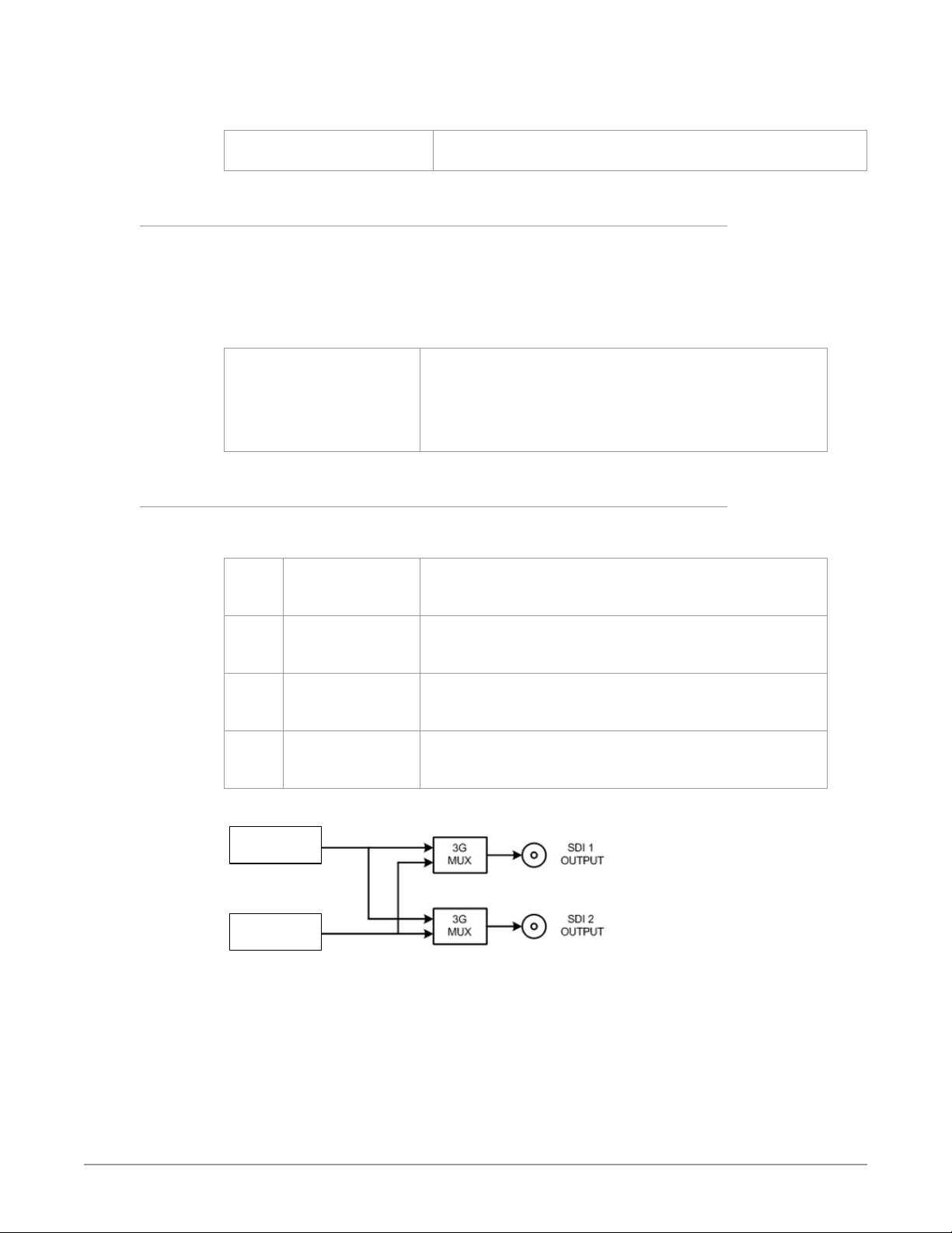
NOTE: The Dynamic Range Clamp parameter is only active when PQ BT.2020 1000 Nits
or Hybrid Log Gamma BT.2100 HDR video is being output.
No Clamp (default)
100 Nits
3.0 Link Config SDI1, 2, 3, 4
(4Ch only) These parameters determine how 1080p50/60 signal transport is
configured for the Video Processor output BNC connectors. The menu names
and parameters available depend on the currently selected Video Processor. For
example, if Video Processor 1 is selected, the menu title will be 2.0 Link Cfg SDI1
identifying the primary output BNC connector used by that Video Processor. For
Video Processor 2 the menu title will be 2.0 Link Cfg SDI2, etc.
Sngl Link LvlA (default)
Dual Link
Sngl Link LvlB
3.1 Level B SDI1, 2, 3, 4
(4Ch only) When Single Link Level B has been selected above, the parameters on
the menu below become available for the selected Video Processor.
VID1 Vid1 (default)
Vid1 + Vid 2
VID2 Vid2 (default)
Vid1 + Vid 2
VID3 Vid3 (default)
Vid3 + Vid 4
VID4 Vid4 (default)
Vid3 + Vid 4
O (no clamp processing).
Output is cleanly compressed to 100 Nits SDR.
Sets the output transport to 3Gb Level A (single connector).
Sets the output transport to 1.5Gb Dual Link (two connectors,
ST 372).
Sets the output transport to 3Gb Level B-DL (single connector).
When Level B is selected a sub menu becomes available to
choose the Video Processor(s).
Selects only the Vid 1 Processor signal for output.
Select both the Vid1 and Vid2 Processor signals for output (Dual
Stream).
Selects only the Vid 2 Processor signal for output.
Select both the Vid1 and Vid2 Processor signals for output (Dual
Stream).
Selects only the Vid 3 Processor signal for output.
Select both the Vid3 and Vid4 Processor signals for output (Dual
Stream).
Selects only the Vid 4 Processor signal for output.
Select both the Vid3 and Vid4 Processor signals for output (Dual
Stream).
Figure 30. Dual Stream 3G MUX Schematic
HD/SD
Video Processor 1
HD/SD
Video Processor 2
See Figure 14 on page 36 for more information.
FS-HDR Frame Synchronizer/Converter/HDR-WCG Processor v1.0r1 80 www.aja.com
Page 81
3.0 Link Config SDI1-4
(Single Ch only) These parameters determine how 1080p50/60 signal transport is
configured for the Video Processor output BNC connectors.
QuadLnk Lvl A (default)
QuadLnk LvlB
Sngl Lnk LvlA
Dual Link
Sngl Lnk LvlB
See "Single Channel Mode Output Examples" on page 38 .
4.0 Link Config SDI5-8
(Single CH only) These parameters determine how 1080p50/60, 6Gb, and 12Gb
signals are formatted for the Video Processor SFP output ports.
QuadLnk Lvl A (default)
QuadLnk Lvl B
Sngl Lnk LvlA
Dual Link
Sngl Lnk LvlB
NOTE: 6Gb and 12Gb signal output requires compatible SFP modules.
See "Single Channel Mode Output Examples" on page 38 .
Sets the output transport to Quad Link Level A (four
connectors).
Sets the output transport to Quad Link Level B-DL (four
connectors).
Sets the output transport to 3Gb Level A (single connector).
Sets the output transport to 1.5Gb Dual Link (two connectors)
Sets the output transport to 3Gb Level B-DL (single connector).
Sets the output transport to Quad Link Level A (four connectors).
Sets the output transport to Quad Link Level B-DL (four
connectors).
Sets the output transport to 3Gb, 6Gb, or 12Gb Level A (single
connector).
Sets the output transport to 1.5Gb or 3Gb Dual Link (two
connectors)
Sets the output transport to 3Gb Level B-DL (single connector).
5 Output Image Mapping
(Single Ch only) This parameter sets the structure of the UHD or 4K output video.
The image can be divided into four quadrants (Square Division [SQD] format, see
SMPTE 425-3, Appendix B), or interleave (2 Sample Interleave [2SI] format (see
SMPTE 425-5, Section 8).
Quadrant (default)
Interleave
6 SD Aspect Ratio
This parameter selects the type of SD-to-SD Aspect Ratio Conversion (ARC)
performed on an incoming selected SD source input. This parameter has an effect
only when the input and output are both SD (525i or 625i).
O (default)
Letterbox
H Crop
Pillarbox
V Crop
14x9
The output is Quadrant format (Square Division).
The output is Two Sample Interleave format. The front panel 2SI LED
will light when selected.
No ARC conversion will be performed.
Selects the indicated ARC conversion.
FS-HDR Frame Synchronizer/Converter/HDR-WCG Processor v1.0r1 81 www.aja.com
Page 82
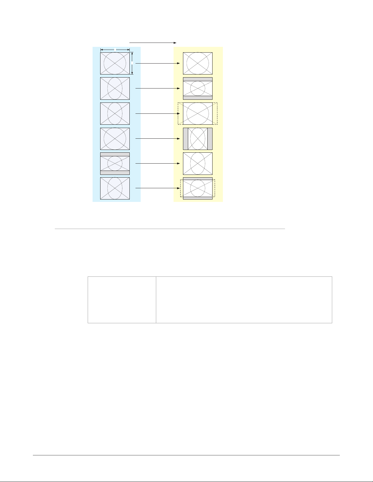
SD Aspect Ratio Conversion Illustrations
Figure 31. SD Aspect Ratio Conversion Illustrations
4:3 Converts To These displays on 4:3
4
7 Upconvert Mode
These parameters select the type of upconversion the Video Processor performs
on the selected input. This parameter has an effect only when the input has a
narrower aspect ratio than the output (SD > HD, HD > 2K). When converting from
2K, the selections do not precisely describe the resulting picture. For example,
4x3 pillar is not precisely 4x3, and 14x9 is not precisely 14x9. However, picture
scaling is such that the visual effect closely resembles an SD-to-HD upconvert.
3
O
(no conversion)
Letterbox
H Crop
Pillarbox
V Crop
14:9
4x3 Pillar (default)
14x9 Pillar
Full Screen
LB to Full
Wide Zoom
NOTE: Any Custom Size/Pos values (only available in Four Channel Mode) will be applied
Results in 4x3 image at center screen with black sidebars.
Results in 14x9 image, zoomed slightly to ll a 14x9 image with
sidebars.
Anamorphic full screen display.
Image is zoomed to t the full screen (letterbox).
Using a combination of zoom and stretch, the image is sized to t a
16x9 screen (this can introduce a small aspect ratio change).
on top of this settings.
FS-HDR Frame Synchronizer/Converter/HDR-WCG Processor v1.0r1 82 www.aja.com
Page 83
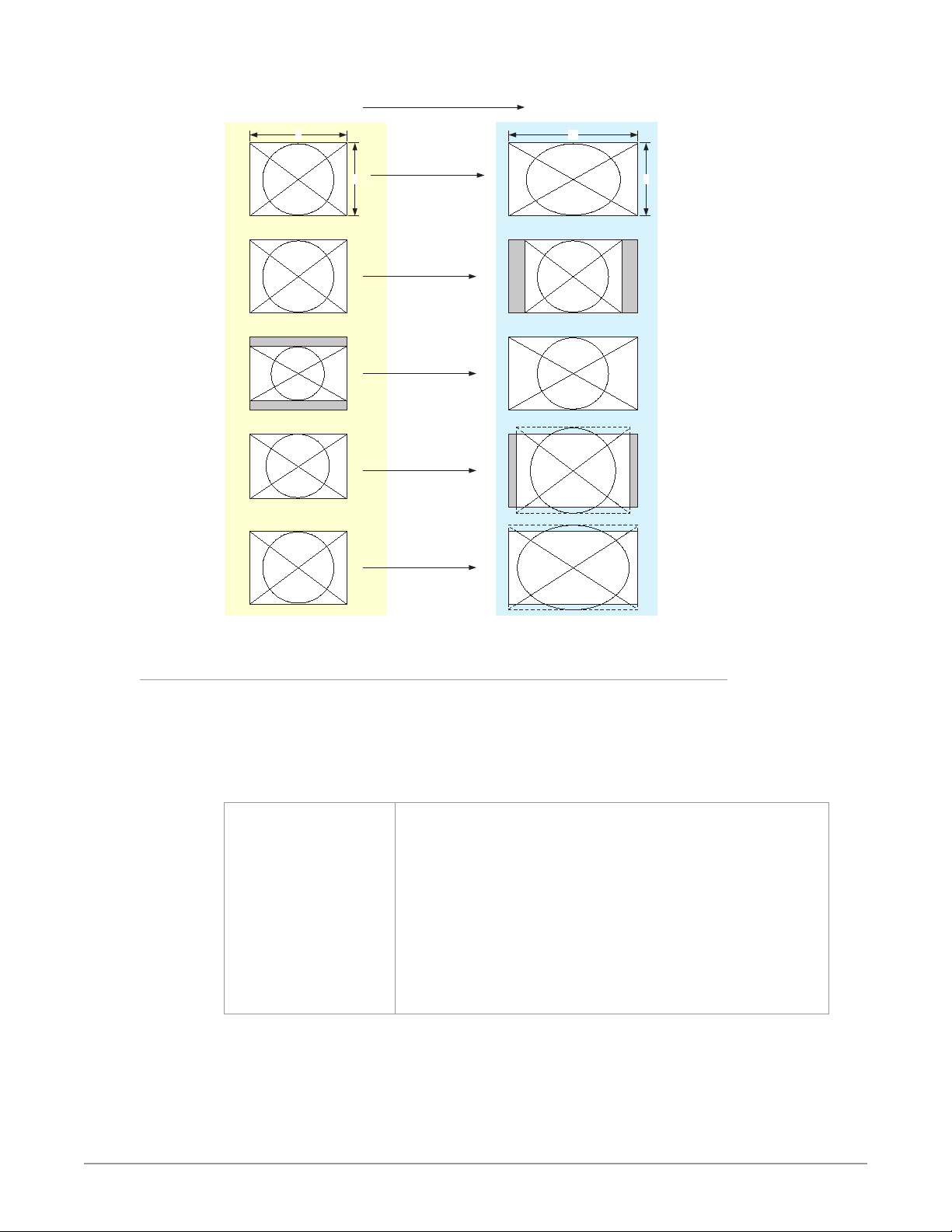
Upconvert Illustrations
Figure 32. Upconvert Illustrations
4:3 Upconverts To These displays on 16:9
4
Full Screen
3
4:3 Pillar
LB to Full
14:9 Pillar
16
9
8 Downconvert Mode
These parameters select the type of down conversion the Video Processor
performs on the selected input. This parameter has an effect only when the
input has a wider aspect ratio than the output (HD > SD, 2K>HD). When down
converting from 2K, the selections do not precisely describe the resulting picture.
For example, 14x9 is not precisely 14x9. However, picture scaling is such that the
visual effect closely resembles an HD-to-SD downconvert.
Crop (default)
Anamorphic
14:9
Auto AFD
Letterbox
Wide Zoom
Image is cropped to t new screen size.
HD image is converted to full-screen SD with a 16x9 aspect ratio
(anamorphic).
Image is reduced slightly with aspect ratio preserved. Black is added
top and bottom, and the left and right sides are cropped.
Automatically selects the best Downconvert mode based on the
input video’s Active Format Description (AFD) code. If the input
video is not carrying an AFD VANC code, the Downconverter
defaults to the mode specied in the Downconvert AFD Dt menu.
With this selection any Custom Size/Pos settings and Region Of
Interest settings are ignored.
Image is reduced with black top and bottom added to image area,
with the aspect ratio preserved.
NOTE: Any Custom Size/Pos values (only available in Four Channel Mode) will be applied
on top of this settings.
NOTE: Any Custom Size/Pos values (only available in Four Channel Mode) will be applied
on top of this settings EXCEPT when Downconvert Mode is set to Auto AFD.
FS-HDR Frame Synchronizer/Converter/HDR-WCG Processor v1.0r1 83 www.aja.com
Page 84
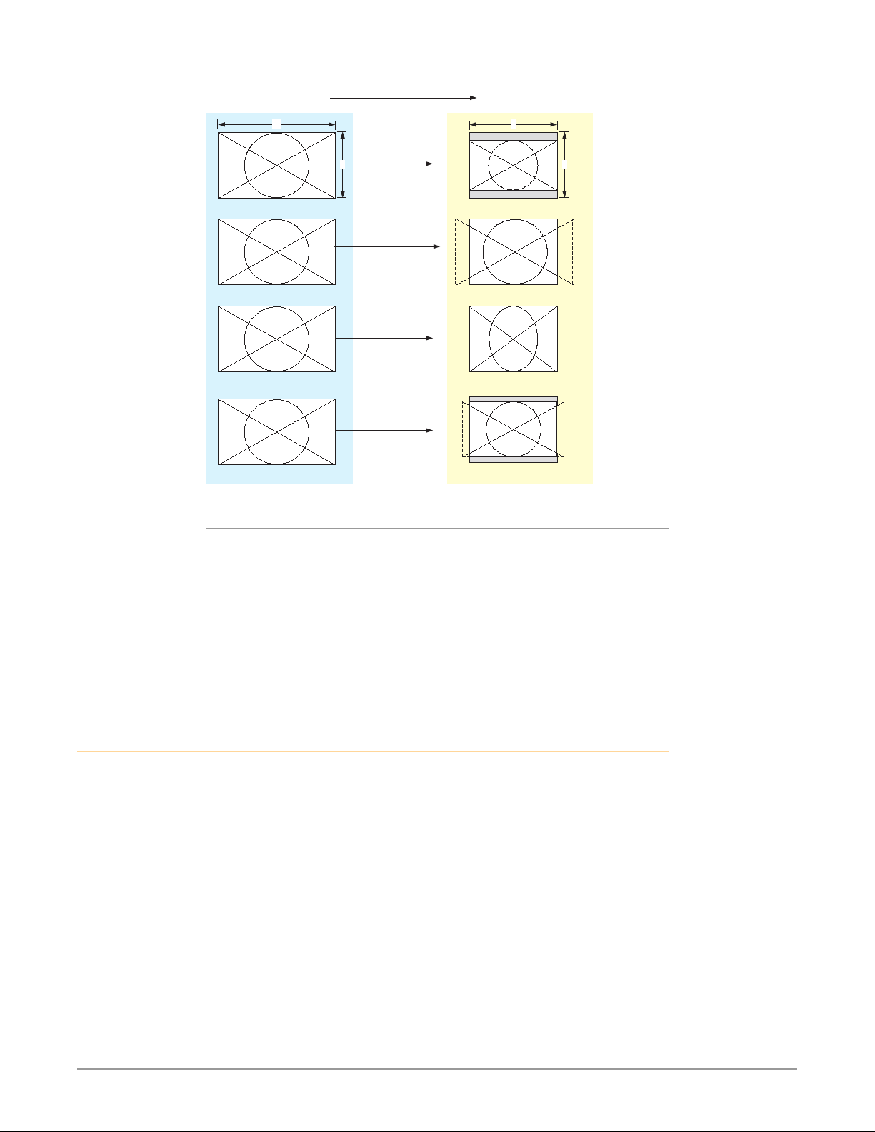
Downconvert Illustrations
Figure 33. Downconvert Illustrations
16:9 Downconverts To These displays on 4:3
16
AFD and Conversion
9
4
Letterbox
3
Crop
Anamorphic
14:9
Active Format Description (AFD) codes are carried in the vertical ancillary
(VANC) portion of HD SDI video signals, specified in SMPTE 2016 as follows: “AFD
information is intended to guide DTV receivers and/or intermediate professional
video equipment regarding the display of video of one aspect ratio on a display
of another aspect ratio.” Because Auto AFD mode fully defines the size, position,
and aspect ratio of the output raster, any Custom Size/Pos settings and any
Region Of Interest settings are ignored, and those menus are hidden. FS-HDR AFD
processing (passing, removing, and re-inserting) occurs based on the setting of
parameter "1.1 AFD Out" on page 75.
SCALE Menu Group
IM PORTA NT: In Four Channel Mode, the settings in this menu group apply only to the
selected Video Processor (VID1- VID 4).
Custom Conversion Settings
The custom settings determine the image size and shape for Upconvert mode if
you choose the Custom selection for those modes.
Custom settings are stored separately for each Conversion Mode. Values for each
of the Upconvert modes and SD Aspect Ratio modes (excluding OFF), plus no
conversion (or HD CrossConvert), are independently stored.
FS-HDR Frame Synchronizer/Converter/HDR-WCG Processor v1.0r1 84 www.aja.com
Page 85
1.0 Custom Size/Pos
This parameter turns custom image settings On or Off. When Hide Inactive is on,
the Custom Size/Position controls are only displayed when Custom Size/Pos is
On. When Custom Size/Pos is Off, modified parameters are skipped in the menu
system, and the UFC hardware is programmed for unity.
This menu is also not displayed when Active Format Description (AFD) is in
control of the Conversion Mode.
NOTE: The Custom Size/Pos feature is not available in Single Channel Mode if both the
inputs and outputs are UltraHD/4K.
O (default)
On
Sets this parameter and related custom size/pos parameters to o.
Enables this parameter and related custom size/position parameters.
1.1 Custom Size
This parameter changes the H and V size of the output picture by the specified
percentage (%) while maintaining the current aspect ratio.
100% (default)
10% to 200%
Maintains 100% picture size for the selected format.
Enables changing the picture size.
1.2 Custom Aspect
This parameter changes the H/V aspect ratio of the output picture while
maintaining the current V size (Aspect < 0) or H size (Aspect > 0).
0.000 (default)
-0.500 to +0.500
Maintains the normal 100% aspect ratio for the selected format.
Enables changing the aspect ratio.
1.3 Custom H Position
This parameter changes the H position of the output picture.
0% (default)
-100% to +100%
Maintains the normal horizontal position of the selected format.
Enables changing the horizontal position.
1.4 Custom V Position
This parameter changes the V position of the output picture.
0% (default)
-100% to +100%
Maintains the normal 100% vertical position of the selected format.
Enables changing the vertical position.
1.5 Custom Left Crop
This parameter changes the Left picture crop position.
100% (default)
+10. 0% to +10 0 .0%
FS-HDR Frame Synchronizer/Converter/HDR-WCG Processor v1.0r1 85 www.aja.com
Maintains the normal left side position of the selected format.
Enables changing the left side position.
Page 86
1.6 Custom Right Crop
This parameter changes the Right picture crop position.
100% (default)
+10. 0% to +10 0 .0%
1.7 Custom Top Crop
This parameter changes the Top picture crop position.
100% (default)
+10. 0% to +10 0 .0%
1.8 Custom Bottom Crop
This parameter changes the bottom picture crop position.
100% (default)
+10. 0% to +10 0 .0%
Region of Interest (ROI)
The Region of Interest parameters select a portion of the input picture that will
be used for scaling and/or positioning. The selected area can then be scaled to
a standard pillarbox or letterbox size and shape (On Square), or it can be set to a
full screen input image (On Full). On Full may cause image distortion if it is used to
expand an odd-shaped region of interest to full screen.
NOTE: The ROI feature is not available in Single Channel Mode if both the inputs and
outputs are UltraHD/4K.
Maintains the normal right side position of the selected format.
Enables changing the right side position.
Maintains the normal top position of the selected format.
Enables changing the top position.
Maintains the normal bottom position of the selected format.
Enables changing the bottom position.
The ROI Setup mode allows you to preview the edges of your selected Region Of
Interest as you set it up. After selecting the desired region using the Setup Cursor,
you can take the region to air by setting Region Of Interest to On Square or On
Full.
The Setup mode is not required to operate the ROI feature. The edges of the
Region Of Interest can also be adjusted while in On Square or On Full modes
2.0 Region of Interest
This parameter turns the Region of Interest settings On or Off. When enabled,
the ROI Left, Right, Top, and Bottom controls define the rectangular shape and
position of the ROI.
O (default)
Setup
On Square
On Full
Interactions occur between ROI settings and other parameters:
• The Region of Interest menu is not displayed when Active Format Description
(AFD) is in control of the Conversion Mode.
• Custom Size and Position settings work interactively with ROI, but Custom
Crop settings are disabled. Custom Size/Pos is also temporarily disabled while
in the ROI Setup mode.
Turns o the ROI feature.
Enables ROI cursor.
Enables ROI and sets video to a pillarbox or letterbox shape.
Enables ROI, and expands the ROI area to full screen.
FS-HDR Frame Synchronizer/Converter/HDR-WCG Processor v1.0r1 86 www.aja.com
Page 87
2.1 ROI Left
This parameter sets the left boundary of the ROI.
Variable (default=100%) Sets ROI left boundary to 10-100% of full screen in 0.1% increments.
For 1% increments, hold down the Video button.
2.2 ROI Right
This parameter sets the right boundary of the ROI.
Variable (default=100%) Sets ROI right boundary to 10-100% of full screen in 0.1% increments.
For 1% increments, hold down the Video button.
2.3 ROI Top
This parameter sets the top boundary of the ROI.
Variable (default=100%) Sets ROI top boundary to 10-100% of full screen in 0.1% increments.
For 1% increments, hold down the Video button.
2.4 ROI Bottom
This parameter sets the bottom boundary of the ROI.
Variable (default=100%) Sets ROI bottom boundary to 10-100% of full screen in 0.1%
KEYER Menu Group
IM PORTA NT: In Four Channel Mode, the settings in this menu group apply only to the
selected Video Processor (VID1- VID 4).
1 Background Fill
This parameter selects the background source used to fill any part of the
processor output raster not filled with video from the main input video. For
example, when the Video Output Mode selection is Sidebars, this parameter
selects the video source for the Sidebars.
Black (default)
Matte
Vid 1, 2, 3, 4 (4Ch only)
2 Sidebar Edge
increments. For 1% increments, hold down the Video button.
Selects black as the background ll video.
Selects matte as the background ll video.
Select the output of another Video Processor as background ll
video.
The parameter adjusts the sidebar position where the center video meets the
pillarbox background video on both sides. The underlying hardware feature is
the same as Custom Right Crop and Custom Left Crop. This is effectively an extra
handle on the Left Crop and Right Crop parameters.
FS-HDR Frame Synchronizer/Converter/HDR-WCG Processor v1.0r1 87 www.aja.com
Page 88
The Crop and Sidebar Edge controls are additive; increasing Sidebar Edge
(making the sidebars larger and the center-video smaller), equates to setting Left
and Right Crop values to smaller percentages. The Sidebar Edge can be set to 0
through +128. A value of 0 produces a 4:3 center. Positive values produce wider
sidebars (and a narrower center).
0 (default)
0 to +128 (Variable)
3.1 Matte Luma
This parameter determines the Matte Luma level of the background fill.
50% (default)
0–100% (Variable)
3.2 Matte Chroma
This parameter determines the Matte Chroma level of the background fill.
50% (default)
0–100% (Variable)
3.3 Matte Hue
This parameter determines the Matte Hue of the background fill.
0 degrees (default)
0–359 degrees (Variable)
Defaults to 0. Select a width value from 0 through +128 to expand
or shrink the sidebars, which are lled with Background video (4
Background Fill). Selecting a larger value causes the center picture
to become narrower while the sidebars expand.
Sets the matte luminance level to the default 50% value.
Sets the matte luminance level from 0–100%.
Sets the matte chrominance level to the default 50% value.
Sets the matte chrominance level from 0–100%.
Sets the matte hue to the default 0 degrees (red).
Sets the matte hue to a value between 0 and 359 degrees.
NOTE: On the front panel, as you turn the Matte Hue ADJUST knob the values wrap from
359 back to 0 degrees.
TIMING Menu Group
IM PORTA NT: In Four Channel Mode, the settings in this menu group apply only to the
selected Video Processor (VID1- VID 4).
These parameters adjust Video Processor horizontal and vertical output timing in
reference to the genlock source already selected, and permits adding up to 6 full
frames of output delay.
NOTE: Unlike most knob-adjustable parameters, on the front panel menu this
parameter automatically wraps around from the maximum value to 0 (and vice
versa).
1 Output Timing H
When adjusting the horizontal timing (H), this parameter specifies a number of
pixels to offset, from zero to full line width. Adjustment range increments from
0 to the width of the line in pixels. The maximum value varies, depending on the
format already chosen.
Variable Adjustment range increments from 0 to the width of the line in
pixels. The maximum varies, depending on the format chosen.
Default: 0
FS-HDR Frame Synchronizer/Converter/HDR-WCG Processor v1.0r1 88 www.aja.com
Page 89
2 Output Timing V
When adjusting the vertical timing (V), this parameter specifies a number of lines
to offset, moving the screen up to a half a frame up or down.
Variable Adjustment range increments from half a frame up to a half a frame
Output Timing Memory
Independent horizontal and vertical timing values are kept for all available output
formats.
Output Timing Ranges
The table below lists the output timing ranges for various video frame rates.
Table 8. Output Timing Ranges
Output Frame Rate
UHD23.98 0 2749 -562 562
UHD24 0 2749 -562 562
UHD25 0 2639 -562 562
UHD29.97 0 2199 -562 562
UHD50 0 2639 -562 562
UHD59.94 0 2199 -562 562
4K1080p23.98 0 2749 -562 562
4K1080p24 0 2749 -562 562
4K1080p25 0 2639 -562 562
4K1080p29.97 0 219 9 -562 562
4K1080p50 0 2639 -562 562
4K1080p59.94 0 219 9 -562 562
1080i50 0 2639 -562 562
1080i59.94, 1080i60 0 2199 -562 562
1080p23.98, 1080p24 0 2749 -562 562
1080p25 0 2639 -562 562
1080p29.97, 1080p30 0 2199 -562 562
1080p50 0 2639 -562 562
1080p59.94, 1080p60 0 2199 -562 562
1080psf23.98, 1080psf24 0 2749 -562 562
1080psf25 0 2639 -562 562
1080psf29.97, 1080psf30 0 2199 -562 562
2Kx1080p23.98, 2Kx1080p24 0 2749 -562 562
2Kx1080p25 0 2639 -562 562
2Kx1080p29.97, 2Kx1080p30 0 2199 -562 562
2Kx1080p50 0 2639 -562 562
2Kx1080p59.94, 2Kx1080p60 0 2199 -562 562
525i59.94, 525psf29.97 0 857 -262 262
625i50, 625psf25 0 863 -312 312
720p23.98, 720p24 0 4124 -375 375
down in single line increments. The maximum varies, depending
on the format already chosen. Default: 0
Horizontal Vertical
Min Max Min Max
FS-HDR Frame Synchronizer/Converter/HDR-WCG Processor v1.0r1 89 www.aja.com
Page 90
Output Frame Rate
720p25 0 3959 -375 375
720p29.97, 720p30 0 3299 -375 375
720p50 0 1979 -375 375
720p59.94, 720p60 0 1649 -375 375
3 Frame Delay
This parameter adjusts Video Processor output timing.
Variable Adjustment output timing from 0 to 6 frames in one frame
NOTE: This delay amount is in addition to the FS-HDR’s default video latency. In Four
Channel Mode and in Single Channel Mode with no Ultra-HD/4K up or down
conversion, this default latency is nominally two frames at low frame rates
(23.98/24/25/29.97/30 fps) or four frames at high frame rates (50/59.94/60 fps). In
Single Channel Mode with UltraHD/4K up or down conversion being performed
this default latency is nominally 3 frames at low frame rates or five frames at high
frame rates.
Horizontal Vertical
Min Max Min Max
increments.
Default: 0
TSTGEN Menu Group
IM PORTA NT: In Four Channel Mode, the settings in this menu group apply only to the
selected Video Processor (VID1- VID 4).
1 Test Pattern Gen
This parameter turns selects whether test pattern is output by that Video
Processor.
O (default)
On
NOTE: Normal output can be a version of its currently selected input, a Sidebar or
Letterbox display, Black, or a Freeze of last good video, depending on the current
configuration.
2 Test Pattern
This parameter selects the type of test pattern output if Test Pattern Gen is on.
75% Bars (default)
Flat
Black
100% Bars
Normal video is output (no test pattern).
The output is the test pattern generator.
Sets the test pattern to 75% color bars.
Sets the test pattern to at eld gray.
Sets the test pattern to black.
Sets the test pattern to 100% color bars.
FREEZE Menu Group
IM PORTA NT: In Four Channel Mode, the settings in this menu group apply only to the
selected Video Processor (VID1- VID 4).
FS-HDR Frame Synchronizer/Converter/HDR-WCG Processor v1.0r1 90 www.aja.com
Page 91

1 Freeze Output
This parameter tells the FS-HDR to freeze the current video frame on the Video
Processor output. This may be useful either for testing or in case of loss of the
input source.
O (default) Normal video is output (no freeze).
On The FS-HDR captures and freezes the most current video frame and
displays it on the outputs as long as this parameter is set to On.
NOTE: Normal output can be a version of its currently selected input, a Sidebar
or Letterbox display, Black, or a Test Pattern, depending on the current
configuration.
Audio Select Buttons EMBED, AES
IM PORTA NT: These parameters are NOT affected by the selection of Single or Four
Channel Mode.
As described in "Operational Summary" on page 18 the EMBED and AES front
panel buttons select categories of audio.
• EMBED selects SDI embedded audio for control. The FS-HDR supports 16
embedded audio channels for each video channel.
• AES selects both AES and MADI audio for control, each with their own set of
parameter menus. The FS-HDR supports up to 16 AES channels (eight pairs),
and up to 64 MADI audio channels.
When the EMBED or AES button is selected, the three Audio buttons on the right
are used to select a category of parameter menus.
Figure 34. Audio Menu Group Buttons
LEVEL
DELAY
MAP
LEVEL Menu Group
IM PORTA NT: The settings in this menu group apply to the currently selected audio
category (EMBED or AES/MADI). These settings are shared with both Four
Channel and Single Channel modes.
The LEVEL menus provide Level and Phase adjustments for SDI Embedded, AES,
MADI BNC, and MADI Fiber input audio.
EMBED Level Menus
When EMBED is selected, the following SDI Embedded Audio menus are available.
FS-HDR Frame Synchronizer/Converter/HDR-WCG Processor v1.0r1 91 www.aja.com
Page 92

1.0 SDI1 Level
This parameter selects the Audio Level Mode for all 16 SDI1 audio input channels.
The default Unity setting applies 0.0. db gain to all the input channels
Unity (default)
Adjust
When Adjust mode is selected:
• After selecting an individual channel adjustment menu, the ADJUST knob
changes the value shown by 0.5 dB (up or down) for each knob detent.
• The range of adjustment is -18.0dB to +18.0dB.
• Switching from Unity to Adjust will apply the individual level values that were
set in the Adjust mode to the input for each of the channels. Switching from
Adjust to Unity will apply unity (0.0dB) to all channels.
All 16 SDI1 audio input channels are set to 0.0 dB. Individual channel
adjustment menus are hidden.
Each of the 16 SDI1 audio input channel adjusted values are applied to
the audio processor, and the individual channel adjustment menus
become available.
1.1-1.16 SDI1 Level Ch 1
When Adjust is selected above, individual SDI 1 audio channel menus become
available, permitting +/- 18.0 dB level adjustment to each input channel.
2.0-8.0 SDI2-8 Level
Same as 1.0 SDI1 Level menu, except for SDI inputs 2 through 8, and similar level
adjust submenus are available.
9.0 SDI1 Phase
This parameter selects the Audio Phase Mode for all 16 SDI1 audio input channels
The default Unity setting applies normal (non-inverted) phase to all the input
channels.
Unity (default)
Adjust
When Adjust mode is selected:
• After selecting an individual channel adjustment menu, the ADJUST knob
toggles the Phase value shown between Normal and Invert. When Invert is
selected the phase of the audio input on that channel will be inverted.
Switching from Unity to Adjust will apply the individual Phase values that were
set in the Adjust mode to the input for each of the channels. Switching from
Adjust to Unity will apply unity (Normal) to all channels.
All 16 SDI1 audio input channels are set to Normal phase. Individual
channel adjustment menus are hidden.
Each of the 16 SDI1 audio input Phase values (either Normal or Invert)
are applied to the audio processor, and the individual channel
adjustment menus become available.
9.1-9.16 SDI 1 Phase
When Adjust is selected above, individual SDI 1 audio channel menus become
available, permitting inverting the phase of each input channel.
10.0 - 16.0 SDI2-8 Phase
Same as 9.0 SDI1 Phase menu, except for SDI inputs 2 through 8, and similar
phase adjust submenus are available.
FS-HDR Frame Synchronizer/Converter/HDR-WCG Processor v1.0r1 92 www.aja.com
Page 93

AES/MADI Menus
When AES is selected, Level and Phase parameter menus for AES and MADI input
audio are displayed. These menus are the similar to those used for Embedded
Audio SDI1 Level and Phase.
1.0 AES Level
Sixteen AES Level menus (and related submenus) are available.
2.0 MADI BNC Level
Sixty four MADI BNC Level (and related submenus) are available.
3.0 MADIFIB Level
Sixty four MADI Fiber Level (and related submenus) are available.
NOTE: For level adjustment information, see "1.0 SDI1 Level" on page 92.
4.0 AES Phase
Sixteen AES Phase menus (and related submenus) are available.
5.0 MADI BNC Phase
Sixty four MADI BNC Phase (and related submenus) are available
6.0 MADIFIB Phase
Sixty four MADI Fiber Phase (and related submenus) are available.
NOTE: For Phase adjustment information, see "9.0 SDI1 Phase" on page 92.
DELAY Menu Group
IM PORTA NT: The settings in this menu group apply to the currently selected audio
category (EMBED or AES/MADI). These settings are shared with both Four
Channel and Single Channel modes.
The DELAY Menu Group provides delay adjustments for SDI Embedded, AES,
MADI BNC, and MADI Fiber input audio. Delay adjustments are applied to audio
channel pairs.
EMBED Delay Menus
When EMBED is selected, the following SDI Embedded Audio menus are available.
1.0 SDI1 Delay
This parameter selects the Audio Delay Mode for the eight SDI1 audio input
channel pairs. Delay operates on channel pairs only. Delay cannot be adjusted
on any single channel. Channel pairs are grouped as: Channel 1 and 2, Channel
FS-HDR Frame Synchronizer/Converter/HDR-WCG Processor v1.0r1 93 www.aja.com
Page 94

3 and 4,…, Channel 15 and 16. The default Global setting applies the currently
set Global delay value to all eight input channel pairs. The factory default Global
setting is 0 seconds delay, but whatever value the user changes this setting to will
be applied when Global is selected.
Global (default)
Channel Pair
When Channel Pair mode is selected:
• Each of the individual eight SDI1 audio input channel pair delay values are
applied to the input delay of each channel pair.
• The range of delay is -128 to +12288 in units of samples where 48 samples = 1
millisecond.
Switching from Global to Channel Pair will apply the individual delay values that
were set for each individual channel pair. Switching from Channel Pair to Global
will apply the same currently set Global delay value to all the channel pairs.
All eight SDI1 audio input channel pairs are set to the current Global
delay value. Individual channel adjustment menus are hidden.
Each of the eight SDI1 audio input channel pairs delay values are
applied to the input of each channel pair, and the channel pair
adjustment menus become available.
1.1 SDI 1 Delay Global
When Global is selected above, the individual SDI 1 audio channel pair menus are
hidden
SDI 1 Delay Global The ADJUST knob sets the Global delay value. Adjustment range is
-128 to +12288 in units of samples where 48 samples = 1
millisecond.
The Front Panel displays the delay in milliseconds and as fractions of
milliseconds in units of samples.
1.1-1.8 SDI 1 Channel Pair Delay
When Channel Pair is selected above, eight individual SDI 1 audio channel pair
menus become available, permitting adjusting the delay of each input channel
pair.
• Delay adjustment range is -128 to +12288 in units of samples where 48
samples = 1 millisecond. The Front Panel displays the delay in milliseconds
and as fractions of milliseconds in units of samples.
2.0 - 8.0 SDI2-8 Delay
Same as 1.0 SDI1 Delay menu, except for SDI inputs 2 through 8, and similar delay
adjust submenus are available.
AES/MADI Delay Menus
When AES is selected, Delay parameter menus for AES and MADI input audio are
displayed. These menus are the similar to those used for Embedded Audio SDI1
Delay.
1.0 AES Delay
Sixteen AES Level menus (and related submenus) are available.
FS-HDR Frame Synchronizer/Converter/HDR-WCG Processor v1.0r1 94 www.aja.com
Page 95
2.0 MADI BNC Delay
Sixty four MADI BNC Level (and related submenus) are available.
3.0 MADIFIB Delay
Sixty four MADI Fiber Level (and related submenus) are available.
NOTE: For level adjustment information, see "1.0 SDI1 Delay" on page 93.
MAP Menu Group
IM PORTA NT: The settings in this menu group apply to the currently selected audio
category (EMBED or AES/MADI). These settings are NOT shared with both Four
Channel and Single Channel modes.
The MAP menus provide FS-HDR audio routing controls. Any audio input can be
routed to any audio output, except the Monitor output embedded audio always
matches the monitored video.
About Audio Routing
The following menus control the FS-HDR’s audio routing. The general routing
procedure using the front panel is to select the menu of the audio output with
the SELECT knob, and then select the input source you wish to route to that
output with the ADJUST knob. Channel mapping allows different individual audio
channels to be routed to different individual outputs.
See "System Cabling" on page 33 for more information about FS-HDR signal
routing.
1.0 Vid 1 Audio Out
This parameter selects the audio input sources for the selected FS-HDR Video
Processor’s audio output channels. The factory default for each output is the
corresponding input: i.e. SDI1 to SDI1, SDI2 to SDI2, etc.
SDI1 - 8
AES/EBU
MADI BNC
MADI Fiber
Mix Down 1 L:R The stereo output of the Mix Down 1 Module is routed to the output
Mix Down 2 L:R (4Ch only) The stereo output of the Mix Down 2Module is routed to
Sig Gen 1KHz
Sig Gen 400Hz
Mute
Map The currently congured mapping is applied to each output channel
The selected source channels are routed to the corresponding output
channels.
channels 1 and 2. The other channels are muted.
the output channels 1 and 2. The other channels are muted.
The selected tone or mute is routed to every output channel of the
selected Video Processor.
of the selected Video Processor. Channel mapping menus for each
output become available.
When set to SDI1-8, AES/EBU, or MADI:
• The selected source channels are routed to the corresponding output
channels. For example, SDI1 input Ch n to SDI1 output Ch n, where n = 1 thru
16.
FS-HDR Frame Synchronizer/Converter/HDR-WCG Processor v1.0r1 95 www.aja.com
Page 96

When set to Mix Down
• The stereo output of the Mix Down Module is routed to audio channels 1 and
2 of the SDI output. The other channels are muted.
When set to Sig Gen 1KHz, Sig Gen 400Hz or Mute:
• The selected source (tone or silence) is routed to every output channel.
When set to Map:
• The mapped source is routed to each output channel according to the last
congured mapped source for each channel in the output.
• The following channel map menus become available via the SELECT knob.
1.1-1.16 SDI1 Output Channel
When Map is selected, each listed source can be mapped to each output channel
of the currently selected output menu.
SDI1 Output Ch 1
through
SDI1 Output Ch 16
2.0-4.0 SDI2-4 Audio Out
See "1.0 Vid 1 Audio Out" on page 95
Select the source to route to the selected output from the following:
-SDI1-8 Ch 1 - Ch 16
-AES Ch 1-16
-MADI BNC 1-64
-MADI Fiber 1-64
-Mix Down 1 L
-Mix Down 1 R
-Mix Down 2 L (4Ch only)
-Mix Down 2 R (4Ch only)
-Sig Gen 1kHz
-Sig Gen 400Hz
-Mute
FS-HDR Frame Synchronizer/Converter/HDR-WCG Processor v1.0r1 96 www.aja.com
Page 97

Chapter 5 – Browser Remote Control
Remote FS-HDR Control Via a Web Browser
The FS-HDR web interface consists of a built-in optimized web server that
provides control via a web browser running on a network-attached computer.
The browser screens are presented and described on the following pages,
organized as they appear in the browser.
Supported browsers
• Chrome (all platforms)
• Firefox (all platforms)
• Safari (OSX, Mobile)
• Internet Explorer (versions 10 and higher)
Other browsers are likely to work but are not guaranteed.
Supported RJ-45 Ethernet network connections
• Closed local area network (LAN)
• Straight computer to FS-HDR cable connection
• Broadband wide area network (WAN) with the rewall opened for the FS-HDR
(not recommended since anyone on the internet can then access the FS-HDR)
Internally the FS-HDR senses and adapts to either a “straight-through” CAT 5
Ethernet cable or null-modem (crossover) cable using standard RJ-45 connectors.
No setup or strapping is needed to adapt to the cable.
Browser connection
For browser access, enter the FS-HDR IP address in the browser’s address field.
By default, the FS-HDR is set to automatically connect to your network’s DHCP
server to get an IP address and other network configuration data. You will find the
IP address in the STATUS Menu Group as follows:
1. Press the STATUS button on the FS-HDR front panel.
2. Turn the SELECT knob until you reach status display with the FS-HDR name
at the top.
3. Enter the IP address shown in the IP Addr eld.
When the browser successfully connects to the FS-HDR, the main Status screen
is displayed. If the browser fails to connect, make sure CONFIG settings for IP,
Subnet, and Gateway match the network setup of the browser host. You can
either make the computer match the FS-HDR, or make the FS-HDR match your
computer.
General Web Browser Screen Description
The webpage screens are different, depending on the current FS-HDR operating
mode. All FS-HDR screens share some common elements:
Menu
On the left of each screen is a navigational list of the available screens. Click any of
these items to jump to that screen. Collapse/expand buttons on the upper right
of each menu lets you open and close that menu’s selection list.
FS-HDR Frame Synchronizer/Converter/HDR-WCG Processor v1.0r1 97 www.aja.com
Page 98
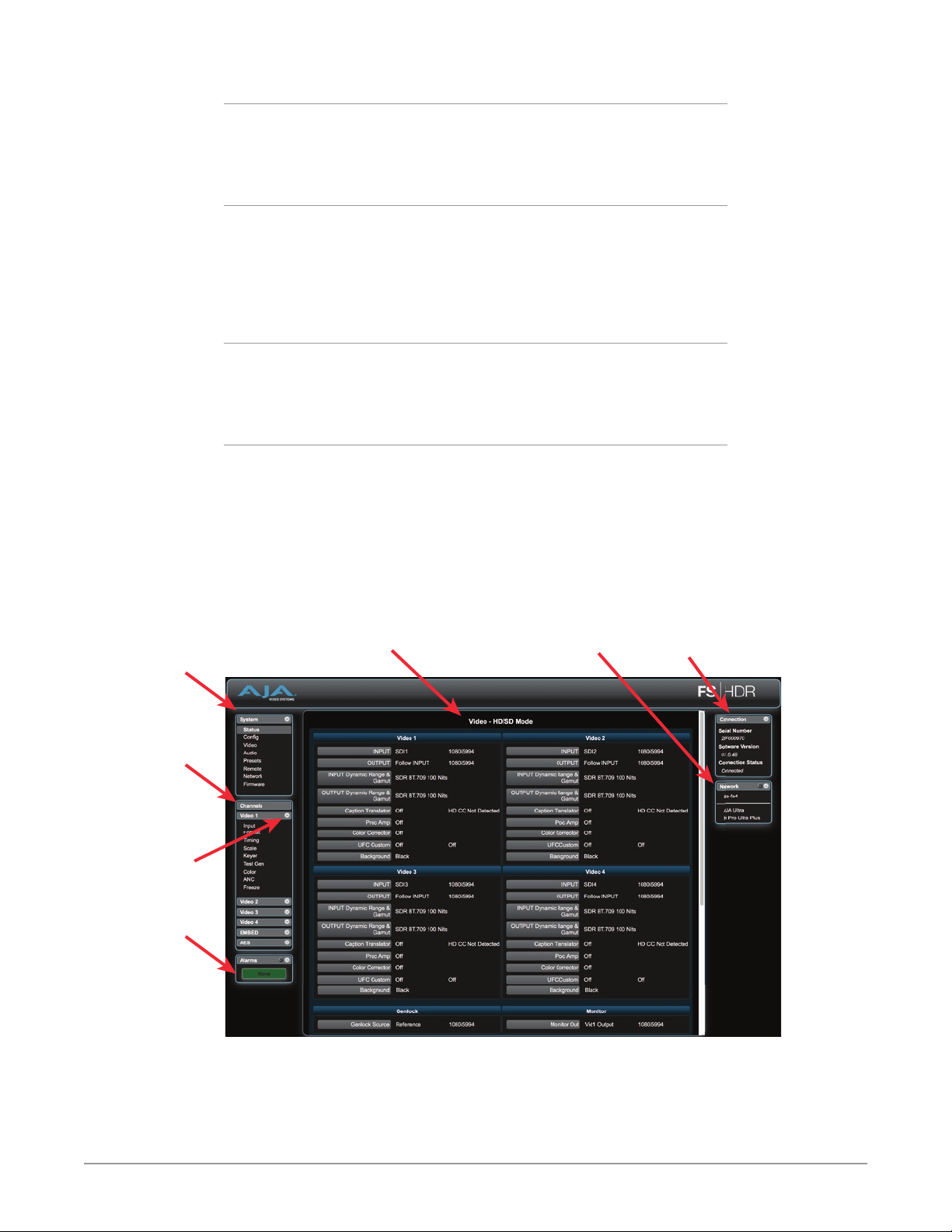
Alarms
The lower left side of the screen shows alarms that alert you to possible problem
conditions, such as disconnected or failed power supplies and video format
incompatibilities.
Status and Menu Display
In the center of each screen you’ll find the main display showing the status and
menu selections for the screen you are viewing. The content of FS-HDR web
screens closely mirrors the parameter menus displayed on the front panel. On all
menus except Status, if you hover the cursor over any parameter, the equivalent
front panel parameter number is displayed.
Connection
The right side of the screen lists FS-HDR system details, including system serial
number, installed software version, and connection status. This information is
useful if you ever have to call AJA Technical Support for help.
Network
The right side of the screen lists AJA systems on the network. The network panel
is divided into two sections by the white line- above the line will be a list of
FS-HDR models on the network- below the line will be a list of other AJA devices
(such as Cion and other FS models) If you right-click any system in the list and
select Identify, the ID LEDs on the unit will blink to identify it. Click on Identify
again to stop the blinking. Another way to identify systems is to notice which
system’s EXT front panel LED flashes when you change any setting from a remote
control device, such as the web browser.
Menu of System
Screens:
Click a screen’s
name to display
that screen.
Menu of Channel
Screens:
Click a screen’s
name to display
that screen.
Collapse/Expand
Button
Alarms
Figure 35. FS-HDR Web Interface, Main Status Screen, Four Ch Mode
Status and Menu
Display Area
AJA Systems on
the Network
System Info
FS-HDR Frame Synchronizer/Converter/HDR-WCG Processor v1.0r1 98 www.aja.com
Page 99
Controlling Multiple FS-HDRs
From any screen, you can see at-a-glance all of the AJA devices present on the
same local LAN as well as the current FS-HDR you are controlling. Clicking on any
of the listed systems will bring up the Status screen of that device.
NOTE: The FS-HDR you control may be running a different software version, so screens
may look different. It’s a good idea to have all your devices running the most
current software and the same version. Also, if the Default Gateway is not
configured properly, other AJA devices will not be visible. If the display shows no
devices found, check the gateway setting.
Resetting Values To Factory Default Settings
FS-HDR web browser screens feature many user controls that can be reset to
factory default values by simply “right-clicking” on the parameter label. When you
right-click, the browser displays a Reset to Factory popup that if clicked will cause
the parameter to be reset.
NOTE: This reset procedure only works with computers that allow right-clicking. Some
computers may not permit this operation.
You can perform a global reset to factory values of all System, Video, Audio, and
most Config parameters (the same set of parameters acted on by a Preset Recall).
Caution! Recall Factory Preset changes the settings for both Single Channel and
Four Channel FS-HDR operating modes to their factory default values. .
To perform a global reset:
1. Go to the Presets screen.
2. Click on the Recall button in the Factory Preset row.
User preferences, network settings, and existing Presets are not affected by
recalling the Factory Preset.
Drop Down Parameter Operation
Most parameters available on the browser are selected from a drop-down list.
The currently active parameter is displayed. Click on the down arrow symbol next
to the parameter to display the list and select an alternative value. The FS-HDR
will immediately operate with the new setting.
Slider Operation
Some screens contain slider controls for setting values. To set a value, you can
click on a slider to select it and then use the mouse to drag the slider to the
position you desire. For fine tuning, while the slider is selected (highlighted by
a blue border), use the keyboard left and right arrow keys to change the value
one unit at a time. Or you can enter the value directly by clicking on the number
displayed above the slider, type in your number then hit Enter to have it take
effect. After setting a slider’s position, click on the page’s background area (blue
highlight turns off) to ensure the change is confirmed and saved.
FS-HDR Frame Synchronizer/Converter/HDR-WCG Processor v1.0r1 99 www.aja.com
Page 100
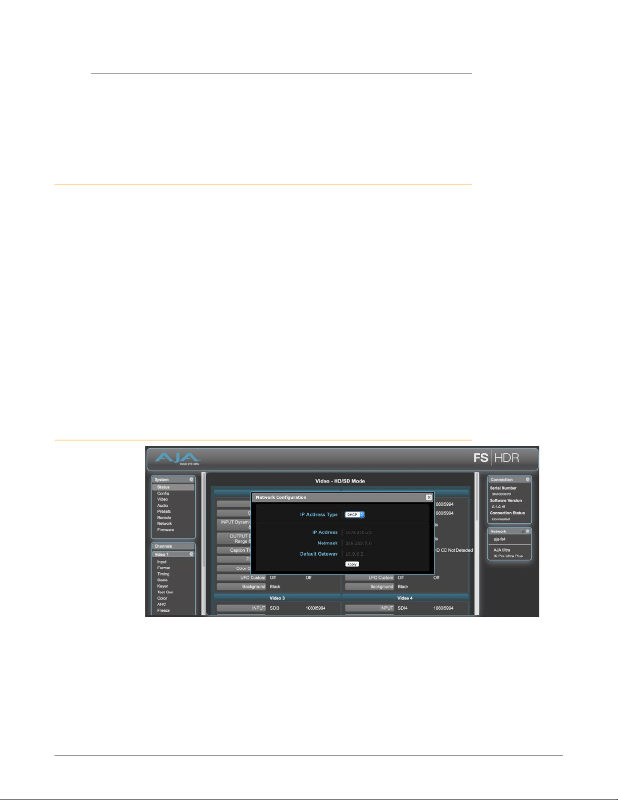
Sub-Menus
Some parameters, when activated, open sub-menus. The sub-menus are a lighter
gray color and have a collapse/expand button on the parent selection. This
lets you collapse the sub-menus to make it easier to configure the system. The
collapsed setting only stays in effect until the user reconnects or refreshes the
browser.
Screen Descriptions
Now that you have had an introduction to how the FS-HDR browser works and
how to navigate the screens, each screen and its settings are described in detail
(click to jump).
• "Network Pane and Network Conguration Screen" on page 100
• "Alarm Conguration Screen" on page 102
• "Status Screen" on page 103
• "Cong Screen" on page 105
• "Video Screen" on page 107
• "Audio Screen" on page 108
• "Presets Screen" on page 109
• "Remote Screen" on page 111
• "Firmware Screen" on page 111
• "Video Channel Screens" on page 112
• "Embedded Audio Channel Screens" on page 116
• "AES (and MADI) Audio Channel Screens" on page 117
Network Pane and Network Configuration Screen
The Network pane on the right side of any screen lists the AJA devices that
appear on the network. This pane includes three additional controls:
• Hover the cursor over any system name to see its IP address.
• Right-click any system and select Identify to blink the system ID LEDs.
• Click the gear-shaped icon in the Network pane (or select Network from the
Menu list on the left side of the screen) to open the Network Conguration
screen listing FS-HDR network settings.
The Network Configuration screen allows you to view and change your FS-HDR’s
network settings and then click Apply to activate them.
FS-HDR Frame Synchronizer/Converter/HDR-WCG Processor v1.0r1 100 www.aja.com
 Loading...