

Page 1
1.
2.
3.
4.
5.
6.
7.
8.
9.
Io
Quick Setup
Overview
Installation and configuration can be summarized as
follows:
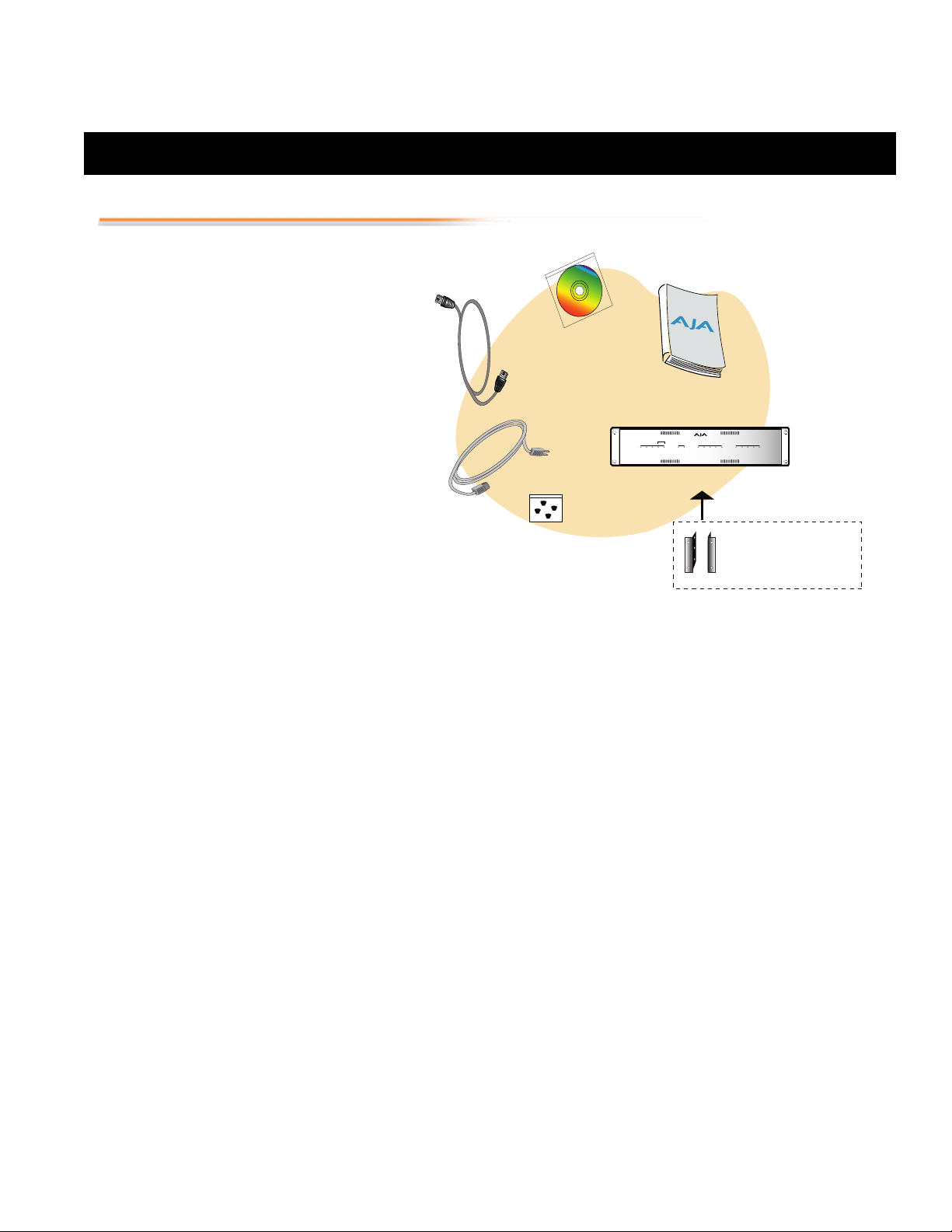
1. Unpack the shipping box
2. If not previously installed on your Power
Mac or Xserve, ensure that Final Cut Pro 4 is
installed as detailed in its user
documentation. Final Cut Pro 4 must be
installed and have been run at least once prior
to installing AJA Io software.
3. Install AJA Io software on your PowerMac
G4 or Xserve from the supplied AJA CDROM
4. Configure the Io chassis for how it will be
mounted: front rack, rear rack, or
deskmount. Use the supplied chassis brackets
or rubber feet as required.
5. Cable the system audio and video sources,
VTR, audio monitor, and video monitor.
Installation Software CD
FireWire
Cable
AC Power Cord
Rubber Feet
For Bottom of
Chassis
Installation and Operation Manual
Status
Mode
Video In
Audio In
FireWire Ref NTSCPower PAL
AJA Io
SDI Component S-VideoPresent Composite
OutIn
Io
™
Panel Chassis
Chassis
Rackmount
Brackets
(already installed on Chassis)
SDI ADAT AES/EBUPresent Analog
Software Installation
Procedure
Locate the CD packaged with your system. Then follow the procedure below to put the required
software on a host system to be used with Io. The system can be either an Apple Power Mac or
Xserve. Minimum system requirements for the host are described in the User Manual shipped with
the system .
Insert the CD in the Power Mac or Xserve. Locate the CD icon on the OS X desktop
Move the cursor to the icon and double click to see the CD contents.
In the CD contents window, locate the package files; they have an icon that looks like a box
and have a “.mpkg” suffix. There should be six different packages.
Out of the six packages, choose the one that best matches your operating environment. For
example, if the system will be used primarily for working with US NTSC digital video, then
select the “IoDigitalNTSC-US.mpkg” file. The file you choose affects the Final Cut Easy
Setup presets that will be installed.
Double-click the desired package to log on and begin software installation.
The system will ask you to authenticate who you are as currently defined on your OS X user
profile. Enter the proper name and password. Click on the OK button.
The installer will launch and you’ll see a series of installer screens. Click Continue to begin
installation.
The next screen shows all the available drives on the Power Mac or Xserve. Click on the
drive that contains your system files (Apple default is “Macintosh HD”). A green arrow will
point to the drive you’ve selected. Click the Continue button to proceed with installation.
At the next screen, click the Install button to place the software on the drive you previously
selected. A system prompt will pop up with a reminder that OS X must be restarted after
installation. Click the Continue Installation button to proceed.
10. The installer will run and put all the necessary Io drivers and software on the desired hard
drive. When it has completed installation, a final screen will be displayed announcing that
“software was successfully installed.”
11. Click the Restart button to complete the installation procedure. The system will perform a
software restart and be ready for use.
Page 2

A
GA
M
O
Externa
to Monitor System
1.
2.
2
Configuring the Io Chassis
3.
4.
Desk Mounting
Front Rackmounting
Rear Rackmounting
System Video/Audio
Cable Connections
The Io chassis should be
plugged into AC power
before you make
connections — although it
should not be switched on.
The AC cord provides a
path to ground for
accidental static discharge
and protects system
equipment.
This figure shows typical
system interconnections for
a system with digital A/V
sources. For an analog
system, use the Component
or composite video
outputs/inputs
corresponding to your
equipment.
To desk mount an Io chassis, follow this procedure. Refer to the illustration Mounting Bracket and
Rubber Feet Locations for visual reference.
Locate the plastic bag containing four rubber feet that was shipped with the system. Each
of the feet have an adhesive-backed flat side.
Turn the Io chassis upside down. Locate the four circular depressions in the bottom of the
chassis, at each of the four corners—these are where the feet will placed.
For each of the four rubber feet: peel off the plastic strip over the adhesive backed side of
the rubber foot and then press it, adhesive side down onto the mounting location.
Press each foot firmly to ensure the adhesive has positive contact and will adhere.
The Io chassis is shipped with chassis brackets already mounted on each side of the front panel,
ready for mounting into a standard 19” equipment rack. No modification is necessary.
For frequent access to connectors, you may prefer rear mounting of the chassis in a 19” rack. Move
the mounting brackets from the factory configuration to the rear by simply removing the two
screws securing each bracket and then moving each to the back of the chassis and securing with the
same screws.
AES/EBU Audio
Ch. 1 In Ch. 2 In Ch. 3 In Ch. 4 In
PUSH
PUSH
PUSHPUSH
Ch. 1 Out Ch. 2 Out Ch. 3 Out Ch. 4 Out
POWER
CMPTR
Analog Audio
PUSH
V
onito
Video Monitor
Component Video
Optional
Genlock
Reference
Loop
Out 1
Ref
SDI
Loop
Out 2
OUT
SDI Video
with Embedded
Audio
l
100 - 240V~
50/60Hz 0.3A
YPbPr
This class A digital apparatus complies
ul
Composite
In
Out
with Canadian ICES-003. Cet appareil
numerique de la classe A est conforme
a la norme NMB-003 du Canada.
In
In
S-Video
Loop Out
Out
Io
www.aja.com
PUSH
Ch. 1-8
In
Optical
Audio
Ch. 1-8
Out
Channels 1-8 Out
Analog Audio Monitor
RS-422
101351
Word Clock
Y/G In
Pr/R In
Pb/B In
Audio
Component
Out
Y/G Out
Pr/R Out
Pb/B Out
IN
ion
RS422
Machine
Control
u
IN
AJA Io
OUT
Computer Monitor
Reference Monitors
Ch. 1/2 In Ch. 3/4 In
Ch. 1/2 Out Ch. 3/4 Out
•
•
•
•
•
•
•
•
•
•
•
•
•
•
•
•
•
•
•
•
•
•
•
•
•
•
•
•
•
•
•
•
•
•
•
•
Dual-port 2Gb Apple Fibre Channel PCI card
(installed in the G4 Macintosh)
Typical Digital System Connections
Digital VTR
Sony DSR-45 (example)
 Loading...