


XR-X77
CD Stereo System
OPERATING INSTRUCTIONS
En (English)
XR-X77
U
Owner’s record
For your convenience, record the model number and serial
number (you will find them on the rear of your set) in the space
provided below. Please refer to them when you contact your
Aiwa dealer in case of difficulty.
Model No. Serial No. (Lot No.)
For assistance and information
(United States and Puerto Rico)
8C-CL2-903-01
020305BSW-H-M
C
MANUAL DE INSTRUCCIONES
MODE D'EMPLOI
E (Español)
F (Français)
En
WARNING
To reduce the risk of fire or electric shock, do not expose
this appliance to rain or moisture.
Explanation of Graphical Symbols:
The lightning flash with arrowhead
symbol, within an equilateral triangle,
is intended to alert the user to the
presence of uninsulated “dangerous
voltage” within the product’s enclosure
that may be of sufficient magnitude to
constitute a risk of electric shock to
persons.
The exclamation point within an
equilateral triangle is intended to alert
the user to the presence of important
operating and maintenance (servicing)
instructions in the literature
accompanying the appliance.
2
IMPORTANT SAFETY INSTRUCTIONS
Read the Operating Instructions carefully and completely before
operating the unit. Be sure to keep the Operating Instructions for
future reference. All warnings and cautions in the Operating
Instructions and on the unit should be strictly followed, as well as
the safety suggestions below.
Warning
To prevent electric shock or injury, these safety instructions should
be followed in the installation, use and servicing the unit.
Installation
Attachments - Do not use attachments not recommended by the
unit manufacturer as they may result in the risk of fire, electric shock
or injury to persons.
Water and Moisture - Do not use this unit near water - for
example, near a bathtub, washbowl, kitchen sink, or laundry tub, in
a wet basement, or near a swimming pool, and the like.
Heat - Do not use this unit near sources of heat, including heating
vents, stoves, or other appliances that generate heat. It also should
not be placed in temperatures less than 5˚C (41˚F) or greater than
35˚C (95˚F ).
Mounting surface - Place the unit on a flat, even surface.
Accessories - Do not place this unit on an unstable cart, stand,
tripod, bracket, or table. The unit may fall, causing serious injury
to a child or an adult, and serious damage to the appliance. Use
only with a cart, stand, tripod, bracket, or table recommended by
the manufacturer, or sold with the unit. Any mounting of the
appliance should follow the manufacturer’s instructions, and should
use a mounting accessory recommended by the manufacturer.
Portable cart - An appliance and cart
combination should be moved with care. Quick
stops, excessive force, and uneven surfaces may
cause the appliance and cart combination to
overturn.
Ventilation - The unit should be situated with adequate space
around it so that proper heat ventilation is assured. Allow 13 cm
clearance from the rear and the top of the unit, and 5 cm from the
each side.
Slots and openings in the cabinet and the back or bottom are
provided for ventilation, and to ensure reliable operation of the unit
and to protect it from overheating, these openings must not be
blocked or covered. The openings should never be blocked by
placing the unit on a bed, sofa, rug or other similar surface. This
unit should not be placed in a built-in installation such as a bookcase
unless proper ventilation is provided.
Object and Liquid Entry - Never push objects of any kind into
this unit through the cabinet slots as they may touch dangerous
voltage points or short-circuit parts that could result in a fire or
electric shock. Never spill liquid of any kind on the unit.
Electric Power
Power Sources - This unit should be operated only from the type
of power source indicated on the marking label. If you are not sure
of the type of power supply to your home, consult your appliance
dealer or local power company. To operate unit on battery power, or
other sources, refer to the operating instructions.
Grounding or Polarization - This unit is provided with a polarized
alternating-current line plug (a plug having one blade wider than
the other). This plug will fit into the power outlet only one way.
This is a safety feature. If you are unable to insert the plug fully into
the outlet, try reversing the plug. If the plug should still fail to fit,
contact your electrician to replace your obsolete outlet. Do not defeat
the safety purpose of the polarized plug.
Power-Cord Protection - Power-supply cords should be routed
so that they are not likely to be walked on or pinched by items
placed upon or against them, paying particular attention to cords at
plugs, convenience receptacles, and the point where they exit from
the product.
Overloading - Do not overload wall outlets, extension cords,
integral convenience receptacles as this can result in a risk of fire
or electric shock.
Outdoor Antenna
Power lines - An outside antenna system should not be located
in the vicinity of overhead power lines or other electric light or power
circuits, or where it can fall into such power lines or circuits. When
installing an outside antenna system, extreme care should be taken
to keep from touching such power lines or circuits as contact with
them might be fatal.
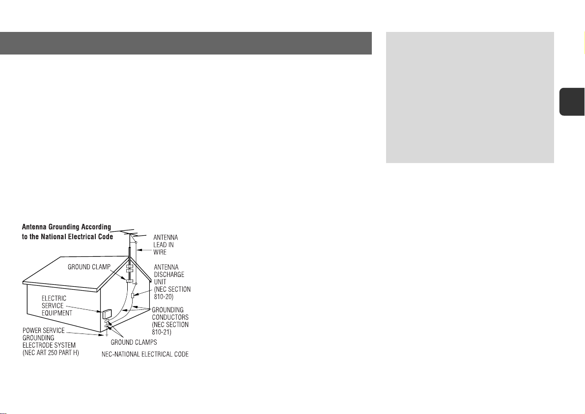
Outdoor Antenna Grounding - If an outside antenna or cable
system is connected to the unit, be sure the antenna or cable system
is grounded so as to provide some protection against voltage surges
and built-up static charges. Section 810 of the National Electrical
Code, ANSI/NFPA No.70, provides information with regard to proper
grounding of the mast and supporting structure, grounding of the
lead-in wire to an antenna discharge unit, size of grounding
conductors, location of antenna-discharge unit, connection to
grounding electrodes, and requirements for the grounding electrode.
See the figure.
Lightning
For added protection for this unit receiver during a lightning storm,
or when it is left unattended and unused for long periods of time,
unplug it from the wall outlet and disconnect the antenna or cable
system. This will prevent damage to the unit due to lightning and
powerline surges.
Maintenance
Cleaning - Unplug this unit from the wall outlet before cleaning.
Do not use liquid cleaners or aerosol cleaners. Use a damp cloth
for cleaning.
Damage Requiring Service
Unplug this unit from the wall outlet and refer servicing to qualified
service personnel under the following conditions:
1) When the power cord or plug is damaged.
2) If liquid has been spilled, or objects have fallen into the unit.
3) If the unit has been exposed to rain or water.
4) If the unit does not operate normally by following the operating
instructions. Adjust only those controls that are covered by the
operating instructions as improper adjustment of other controls
may result in damage and will often require extensive work by a
qualified technician to restore the unit to normal operation.
5) If the unit has been dropped or the cabinet has been damaged.
6) When the unit exhibits a distinct change in performance - this
indicates a need for service.
Do not attempt to service this unit yourself as opening or removing
covers may expose you to dangerous voltage or other hazards. Refer
all servicing to qualified service personnel.
Replacement Parts - When replacement parts are required, be
sure the service technician has used replacement parts specified
by the manufacturer or having the same characteristics as the original
part. Unauthorized substitutions may result in fire, electric shock
or other hazards.
Safety Check - Upon the completion of any service or repairs to
this unit, ask the service technician to perform safety checks to
determine that the unit is in proper operating condition.
TABLE OF CONTENTS
IMPORTANT SAFETY INSTRUCTIONS ......... 2
PREPARATIONS ................................... 4
PARTS AND CONTROLS ......................... 5
ADJUSTMENTS BEFORE OPERATION.......... 7
CD OPERATIONS .................................. 8
RADIO OPERATIONS ........................... 10
SOUND ADJUSTMENTS ........................ 11
TIMER OPERATIONS ........................... 12
REFERENCE ..................................... 14
System and accessories
Main unit CX-LX77
Speakers SX-LX77
Speaker cords
Remote control
FM antenna
AM antenna
En
3
PREPARATIONS
Connection
Plug in the AC power cord to the AC outlet after all other
connections are made.
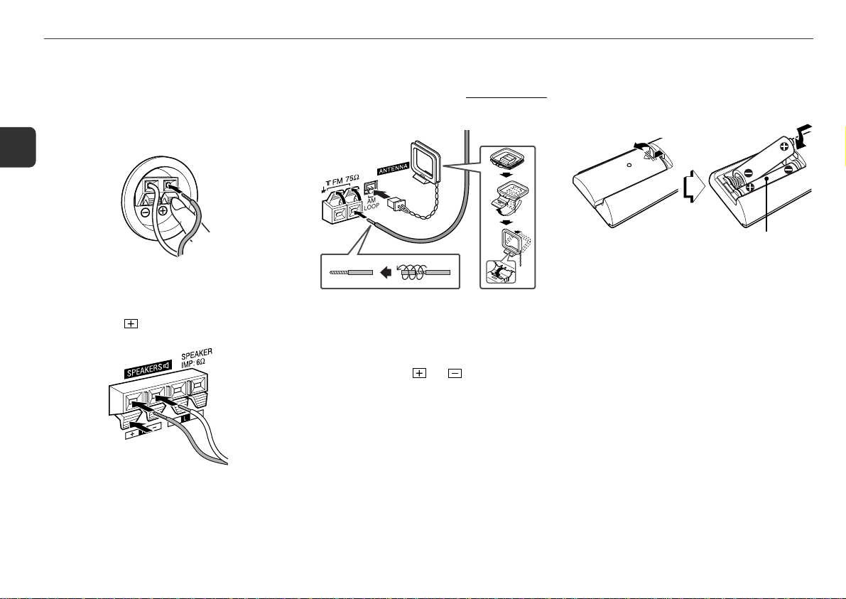
1
Connect the speaker cords to the speakers.
Connect the copper cords to the + terminals and the silver
En
cords to the – terminals.
2
Connect the speakers to the main unit.
Connect the right speaker to the SPEAKERS 3 R terminals
and the left to the SPEAKERS 3 L terminals. The copper
cords go to the
terminals.
3
Connect the supplied antennas.
Connect the FM antenna to the FM 75 Ω terminals and
the AM antenna to the AM LOOP jack. Connect the FM
antenna to the FM 75 Ω terminals without the 2 mark,
as illustrated.
AM antenna
4
Connect the AC power cord to an AC outlet.
The clock will flash on the display.
For setting the clock, see page 12.
Speakers
•Do not short-circuit the
•Do not leave objects generating magnetism or objects
affected by magnetism near the speakers.
Antennas
Keep antennas away from metallic objects, electrical
equipment and cords.
•FM antenna: Extend fully and position for the best
reception. If reception is poor, connect an optional outdoor
antenna to the FM 75 Ω terminals. When connecting an
optional outdoor antenna, be sure to connect the shield braid
of the antenna to the 2 terminal.
•AM antenna: Rotate to find best reception.
FM antenna
and speaker cord leads.
Remote control
Detach the battery compartment lid at the rear of the remote
control and insert two R6 (size AA) batteries with correct
polarity.
R6(AA)
•Replace the batteries with new ones when the operational
distance between the remote control and main unit becomes
shorter.
•Remove the batteries if the unit is not going to be used for
an extended period of time.
•The remote control may not operate if it is used under intense
sunlight or if its line of sight is obstructed.
4
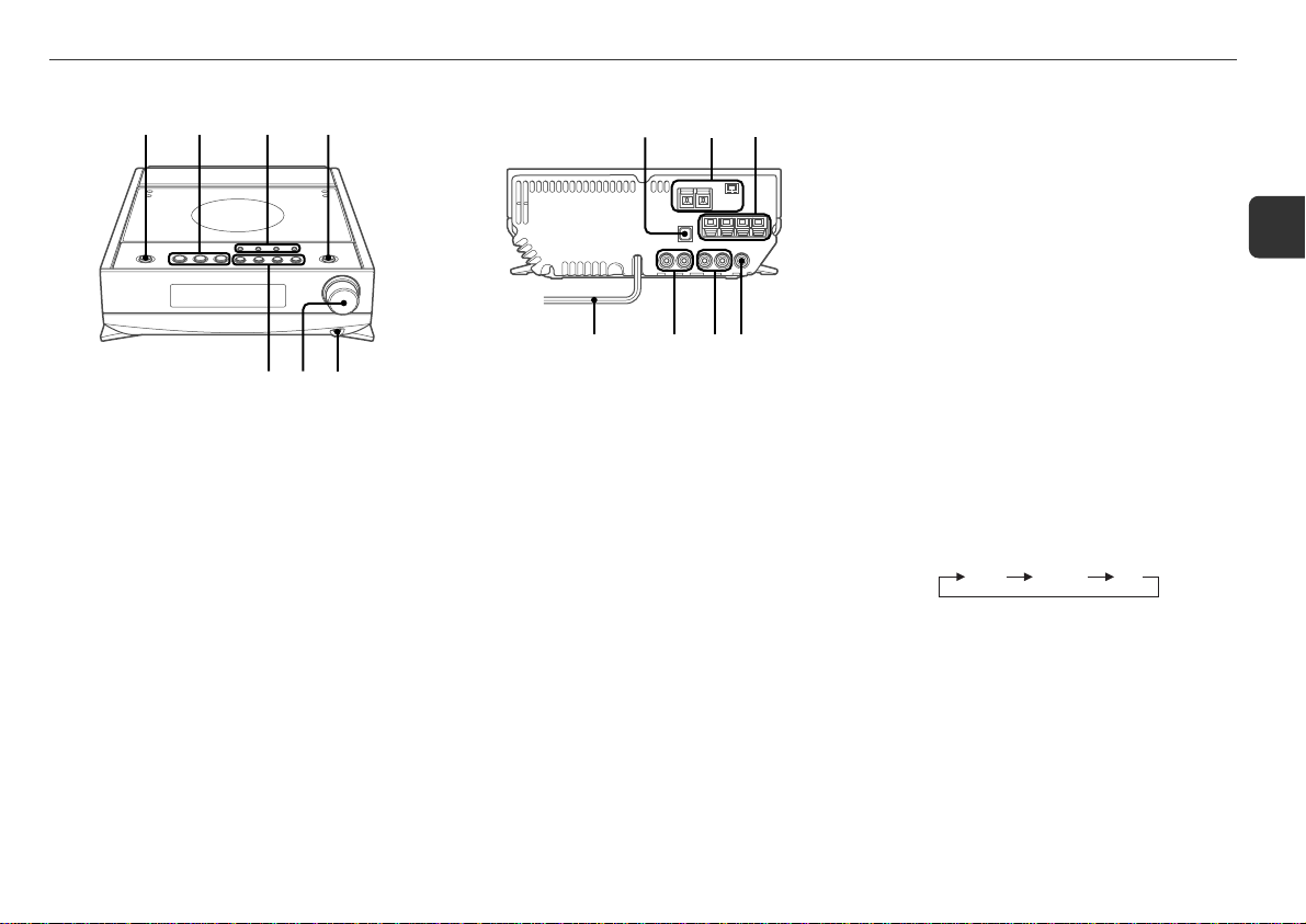
PARTS AND CONTROLS
76
Main unit
12 3
1 POWER 6STANDBY/ON
Switches the unit on and off (standby).
2 TUNER/BAND
Selects Radio function and the radio band.
AUX
Selects the function of external equipment connected to
VIDEO/AUX IN jacks.
ECD
Starts and pauses play.
3 ECO/DIMMER
Selects ECO mode and dimmer mode.
DISPLAY
Changes the display in CD playback mode.
TONE
Selects the sound adjusting mode, "BAS" (bass),
"MID" (middle range) or "TRE" (treble).
SET
Determines the mode.
Stores the received station to preset.
4
5
8
!@
4 z OPEN/CLOSE
Opens or closes the disc compartment.
5 sCLEAR
CD: stops playback.
Radio: clears a preset station.
f/r, t/g (TUNING - ,+)
CD: skips to a previous or a succeeding track when
pressed, searches a track in fast forward or reverse
playback when held down.
Radio: manually tunes up or down within the band.
PRESET
Tune in a preset station.
6 VOLUME
Adjusts the volume.
7 PHONES jack
Plug in optional headphones set with a stereo mini plug
(ø3.5 mm,
1
/8 in.). Speaker output is canceled.
90
#$
8 DIGITAL OUT (OPTICAL) jack
CD digital sound signals can be output through this jack.
Use an optical cable to connect digital audio equipment.
Remove the dust cap from the DIGITAL OUT (OPTICAL)
jack. Then connect an optical cable plug to the DIGITAL
OUT (OPTICAL) jack.
9 AM LOOP jack and FM 75 Ω terminal
Plug in the supplied AM and FM antennas.
0 SPEAKERS3 terminals
Connect the supplied speaker cords.
! AC power cord
@ VIDEO/AUX IN jacks
Accept analog sound signals from external equipment.
Connect external equipment using an optional connecting
cable with RCA phono plugs (red plug to R jack, white
plug to L jack). Refer also to the operating instructions
for your equipment.
To switch function to external input, press AUX.
To change a source name in the display of the
AUX function
Hold down AUX and press POWER while the power is
on.
AUX VIDEO TV
# LINE OUT jacks
Analog sound signals for all functions can be output
through these jacks. Use a cable with RCA phono plugs
to connect audio equipment.
Signals input through the VIDEO/AUX IN jacks are not
output from the LINE OUT jacks.
$ 3SUB WOOFER jack
Connect an optional sub woofer with a built-in amplifier
to the jack.
En
5
 Loading...