

Page 1
For assistance and information
call toll free 1-800-BUY-AIWA
En (English)
E (Español)
F (Français)
88-AR2-903-01
980401CCK-Y-9
(United States and Puerto Rico)
Page 2
ENGLISH
WARNING
TO REDUCE THE RISK OF FIRE OR ELECTRIC SHOCK. DO NOT EXPOSE THIS APPLIANCE TO RAIN OR MOISTURE.
CAUTION
RISK OF ELECTRIC SHOCK
DO NOT OPEN
“CAUTIONTO REDUCE THE RISK OF
ELECTRIC SHOCK,
DO NOT REMOVE COVER (OR BACK).
NO USER-SERVICEABLE PARTS INSIDE.
REFER SERVICING TO QUALIFIED
SERVICE PERSONNEL.”
Explanation of Graphical Symbols:
The lightning flash with arrowhead
symbol, within an equilateral triangle, is
Intended to alert the user to the presence
H
of uninsulated "dangerous voltage" within
the product's enclosure that may be of
sufficient magnitude to constitute a risk
of electric shocK to persons.
The exclamation point within an
equilateral tilangle is intended to alert
the user to the presence of important
operating and maintenance (.servicing)
instructions in the liteiature accom
panying the appliance.
PRECAUTIONS
Read the Operating Instructions carefully and completely before
operating the unit. Be sure to keep the Operating instructions
for future reference. Aii warnings and cautions in the Operating
instructions and on the unit shouid be strictly followed, as well
as the safety suggestions beiow.
Installation
1 Water and moisture — Do not use this unit near water, such
as near a bathtub, washbowi, swimming pool, or the like.
2 Heat — Do not use this unit near heat sources, including
heating vents, stoves, or other appliances that generate heat.
It also should not be placed in temperatures less than 5°C
(41 °F) or higher than 35°C (95°F).
3 Mounting surface — Place the unit on a flat, even surface.
4 Ventilation — The unit should be situated with adequate
space around it so that proper heat ventilation is assured.
Allow 10 cm (4 in.) clearance from the rear and the top of the
unit, and 5 cm (2 in.) from each side.
- Do not place the unit on a bed, rug, or similar surface that
may block the ventilation openings.
- Do not install the unit in a bookcase, cabinet, or airtight
rack where ventilation may be impeded.
5 Objects and liquid entry — Take care that objects or liquids
do not get inside the unit through the ventilation openings.
6 Carts and stands — When placed or
mounted on a stand or cart, the unit
should be moved with care.
Quick stops, excessive force, and
uneven surfaces may cause the unit or
cart to overturn or fall.
7 Wall or ceiling mounting — The unit should not be mounted
on a wall or ceiling, unless specified in the Operating
Instructions.
Owner’s record
For your convenience, record the model number and serial
number (you will find them on the rear of your unit) in the space
provided below. Please refer to them when you contact your
Aiwa dealer in case of difficulty.
Model No.
AV-D50
Serial No. (Lot No.)
1 ENGLISH
Electric Power
1 Power sources — Connect this unit only to power sources
specified in the Operating Instructions, and as marked on
the unit.
2 Polarization — As a safety feature, some units are equipped
with polarized AC power plugs which can only be inserted
one way into a power outlet. If it is difficult or impossible to
insert the AC power plug into an outlet, turn the plug over
and try again. If it is not still inserted easily into the outlet,
please call a qualified service technician to service or replace
the outlet. To avoid defeating the safety feature of the
polarized plug, do not force it into a power outlet.
3 AC power cord
- When disconnecting the AC power cord, pull it out by the
AC power plug. Do not pull the cord itself.
- Never handle the AC power plug with wet hands, as this
could result in fire or shock.
- Power cords should be firmly secured to avoid being
severely bent, pinched, or walked upon. Pay particular
attention to the cord from the unit to the power socket.
- Avoid overloading AC power plugs and extension cords
beyond their capacity, as this could result in fire or shock.
4 Extension cord — To help prevent electric shock, do not
use a polarized AC power plug with an extension cord,
receptacle, or other outlet unless the polarized plug can be
completely inserted to prevent exposure of the blades of the
plug.
5 When not in use — Unplug the AC power cord from the AC
power outlet if the unit will not be used for several months or
more. When the cord is plugged in, a small amount of current
continues to flow to the unit, even when the power is turned
off.
Page 3
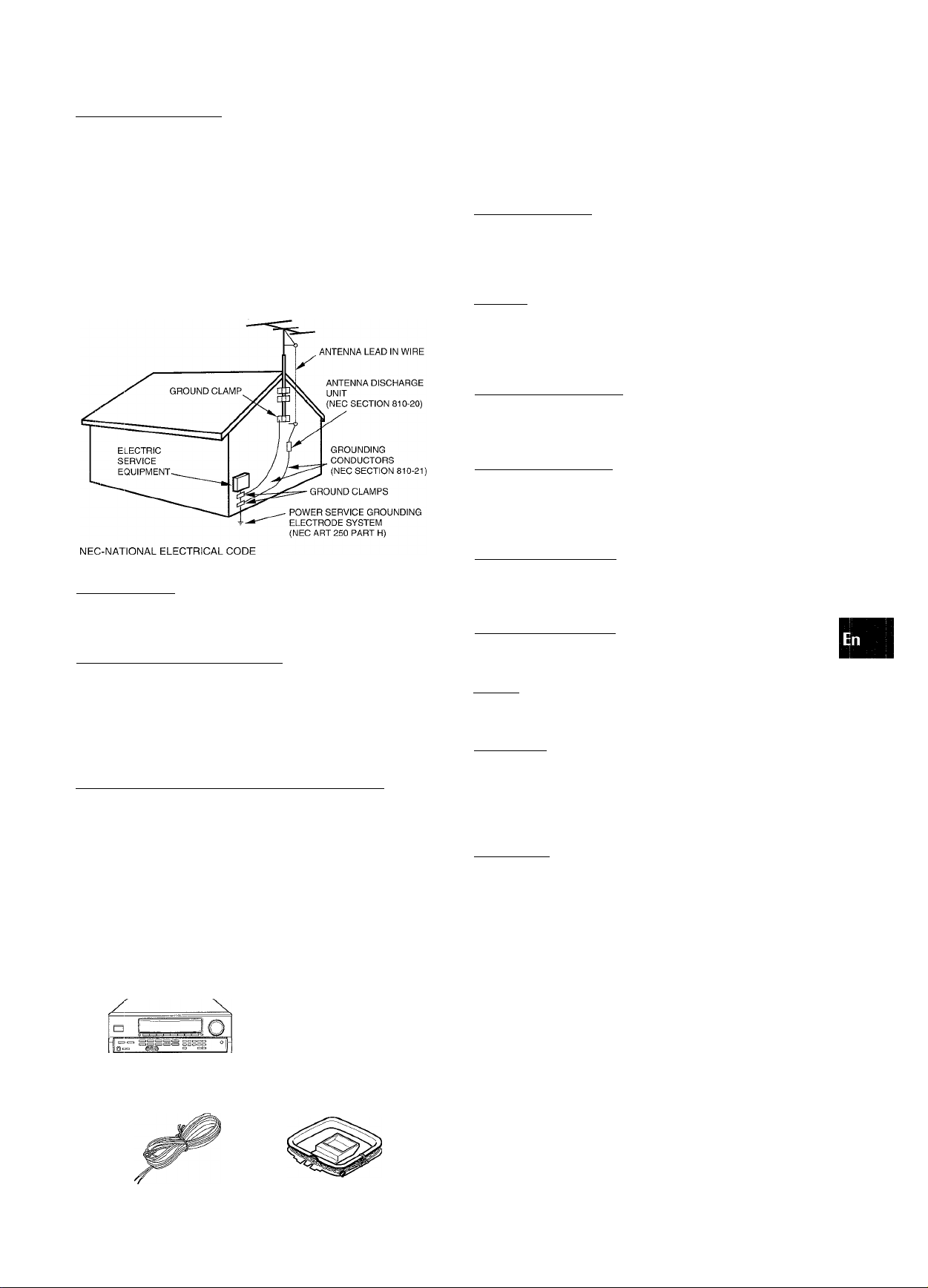
Outdoor Antenna
Power lines — When connecting an outdoor antenna, make
1
sure it is located away from power lines.
Outdoor antenna grounding — Be sure the antenna system
is properly grounded to provide protection against unexpected
voltage surges or static electricity build-up. Article 810 of the
Natienal Electrical Code, ANSI/NFPA70, provides infermation
on proper grounding of the mast, supporting structure, and
the lead-in wire to the antenna discharge unit, as well as the
size of the grounding unit, connection to grounding terminals,
and requirements for grounding terminals themselves.
TABLE OF CONTENTS
PRECAUTIONS.................................................................1
PREPARATIONS
CONNECTIONS
BEFORE OPERATION
SETTING THE CLOCK
____________________________
...............................................................
....................................................
....................................................
3
7
7
Antenna Grounding According to the National Electrical Code
Maintenance
Clean the unit only as recommended in the Operating
Instructions.
Damage Requiring Service
Have the unit serviced by a qualified service technician if:
- The AC power cord or plug has been damaged
- Foreign objects or liquid have gotten inside the unit
- The unit has been exposed to rain or water
- The unit does not seem to operate normally
- The unit exhibits a marked change in performance
- The unit has been dropped, or the cabinet has been damaged
DO NOT ATTEMPT TO SERVICE THE UNIT YOURSELF.
SOUND____________________________________
CUSTOM AUDIO ADJUSTMENT
ELECTRONIC GRAPHIC EQUALIZER.............................9
DSP SURROUND...............................................................9
BASIC OPERATIONS
SELECTION OF AUDIOAfIDEO SOURCE
RECORDING AN AUDIO SOURCE
RADIO RECEPTION
MANUAL TUNING
DIRECT TUNING..............................................................12
PRESETTING STATIONS
DOLBY SURROUND
SELECTING DOLBY PRO LOGIC .................................
ADJUSTING SPEAKER LEVEL BALANCE
REMOTE CONTROL
OPERATING TV, CABLE TV, VCR AND CD PLAYER
________________________
_________________________
.........................................................
_________________________
_________________________
......................................
.....................
................................
...............................................
...................
12
....
8
10
11
13
14
15
16
TIMER_____________________________________
SETTING THE SLEEP TIMER.........................................17
GENERAL__________________________________
CARE AND MAINTENANCE
SPECIFICATIONS
TROUBLESHOOTING GUIDE.........................................19
PARTS INDEX
.......................................................
.................................................................
...........................................
18
17
19
Check your unit and accessories
AV- D50 Stereo receiver Remote control
FM antenna
Operating Instructions, etc.
AM antenna
APPENDIX
ID CODES FOR TV.................................................... A-1
ID CODES FOR CABLE TV......................................... A-2
ID CODES FOR VCR
ID CODES FOR CD PLAYER
_________________________________
....................................................
........................................
ENGLISH 2.
A-3
A-4
Page 4
I*
PREPARATIONS
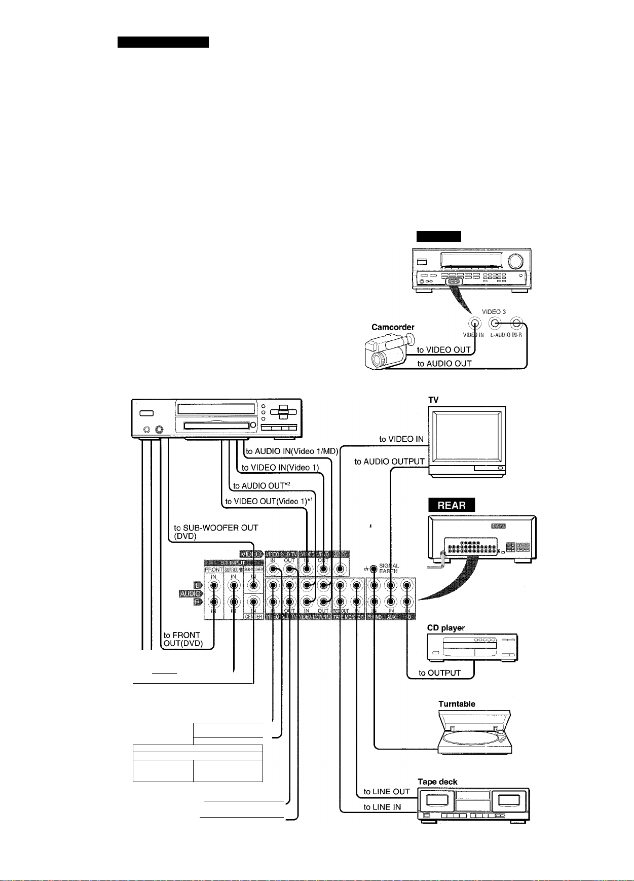
CONNECTIONS
Before connecting the AC cord
The rated voltage of your unit shown on the rear panel Is 120 V
AC. Check that the rated voltage matches your local voltage.
IMPORTANT
Connect the speakers, antennas, and all other external
equipment first. Then connect the AC cord at the end.
*' Be sure to connect the VIDEO OUT terminal of a DVD player
directly to a TV set, not through this unit. Otherwise, the picture
noise may appear when playing the DVDs copy protected.
Input sound through the 5.1 INPUT terminals cannot be
recorded. When recording the sound from the DVD player,
connect the AUDIO OUT (DOWN MIXING) terminals of the
DVD player to the VIDEO 1/DVD/MD AUDIO IN terminals of
the unit.
When connecting a monaural video, use a stereo-mono
connecting cord (not supplied).
CONNECTING EQUIPMENT
Jacks and plugs of the connecting cord are color-coded as
follows:
Red jacks and plugs : For the right channel of audio signals
White jacks and plugs: For the left channel of audio signals
Yellow jacks and plugs: For video signals
Insert the plugs fully Into the jacks. Loose connections may
produce a humming sound or other noise interference.
FRONT
DVD or Video 1/MD player*'
to SURROUND OUT
.(DVD)
____________
to CENTER OUT(DVD)
_
ENGLISH
Video 2 or
LD/Cable TV*^
to AUDIO OUT
to VIDEO OUT
f
II I I
to AUDIO IN (Video 2)
. to VIDEO IN (Video 2)
Page 5
O’)
•Z.
o
h
c:
<£
c.
UJ
q:
c..
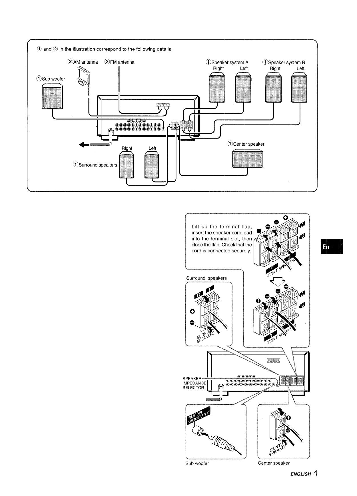
CONNECTING SPEAKERS ®
Speaker terminals
Connect front speakers (system A and/or B), a center speaker,
surround speakers and sub woofer to the corresponding speaker
terminals on the unit:
- the front speaker cords to the FRONT SPEAKERS terminals
- the center speaker cord to the CENTER SPEAKER terminals
- the surround speaker cords to the SURROUND SPEAKERS
terminals.
- for more powerful bass, the sub woofer (with a built-in amplifier,
Aiwa TS-W35 etc.) cord to the SUPER WOOFER Kl jack
Speaker impedance
• Front and center speakers
Use the same impedance speakers for both the front and center
ones.
The SPEAKER IMPEDANCE SELECTOR on the rear should be
set to the position that matches the impedance value of the front
and center speakers.
When using 4 ohm speakers, set the selector to IMP:40. When
using 8 ohm speakers, set the selector to IMP:8i2. Please unplug
the AC cord before setting the selector.
• Surround speakers and super woofer
The SPEAKER IMPEDANCE SELECTOR has no effect on the
SURROUND SPEAKERS terminals and the SUPER WOOFER
<1 jack. For the surround speakers and sub woofer, use speakers
of 8 ohms or more.
Front speakers
Connecting + to +, - to - terminals
To get the proper sound effect, the speaker terminals on the unit
and the speaker should be connected with proper polarity; the -r
terminal on the unit should be connected to the -r terminal on
the speaker (and - to -).
• Be sure to connect the speaker cords correctly as shown in
the illustration on the right column. Improper connections can
cause short circuits in the SPEAKER(S) terminals.
' Do not leave objects generating magnetism near the speakers.
•
Page 6
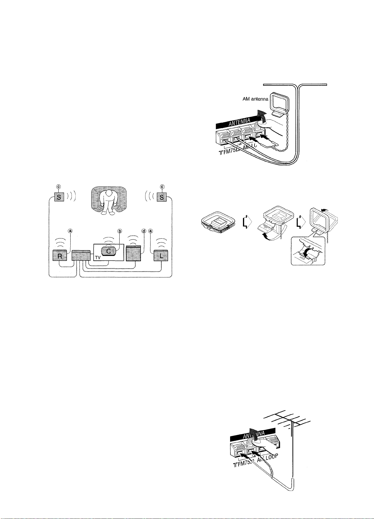
POSITIONING THE SPEAKERS
Position the speakers to make the most of the Doiby Digital
Surround (5.1 CH), Dolby Pro Logic or DSP effect.
CONNECTING THE SUPPLIED ANTENNAS (2)
Connect the FM antenna to the FM 75 i2 terminals and the AM
antenna to the AM LOOP terminals.
(D Front speakers d) Center speaker
Position in the center of the two front speakers. In addition,
position on or below the TV set, if connecting a TV set to the
unit.
© Surround speakers
Place the surround speakers directly to the side of or slightly
behind the listening area. Align them horizontally, about 1
meter (3.2 feet) above ear height.
@ Sub woofer
Place the sub woofer in any place between the two front
speakers.
Sound from the surround speakers or center speaker depends
on the setting of the DSP, Dolby Pro Logic and 5.1 CH function.
FM antenna
To stand the AM loop antenna on a surface
Fix the claw to the slot as shown in the illustration.
To position the antennas FM feeder antenna:
Extend this antenna horizontally in a T shape and fix its ends to
the wall.
AM loop antenna:
Position for the best reception.
• Do not bring the FM antenna near metal objects or curtain rails.
• Do not bring the AM antenna near other external equipment,
the unit itself, the AC power cord or speaker cords, as noise
will be picked up.
• Do not unwind the AM loop antenna wire.
CONNECTING AN OUTDOOR ANTENNA
For better FM reception, use of an outdoor antenna is
recommended. Connect the outdoor antenna to the FM 75 Ì2
terminals.
ENGLISH
Page 7
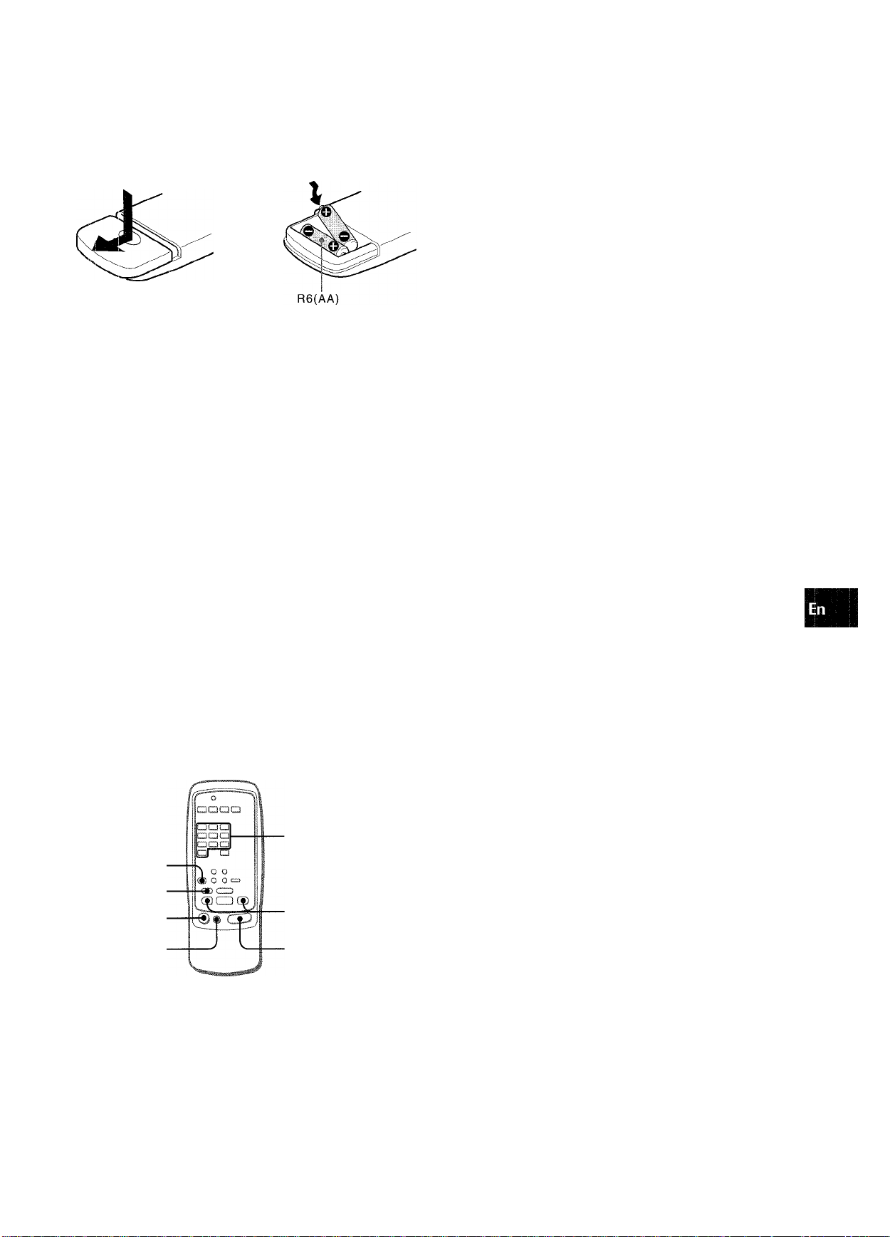
ABOUT THE REMOTE CONTROL
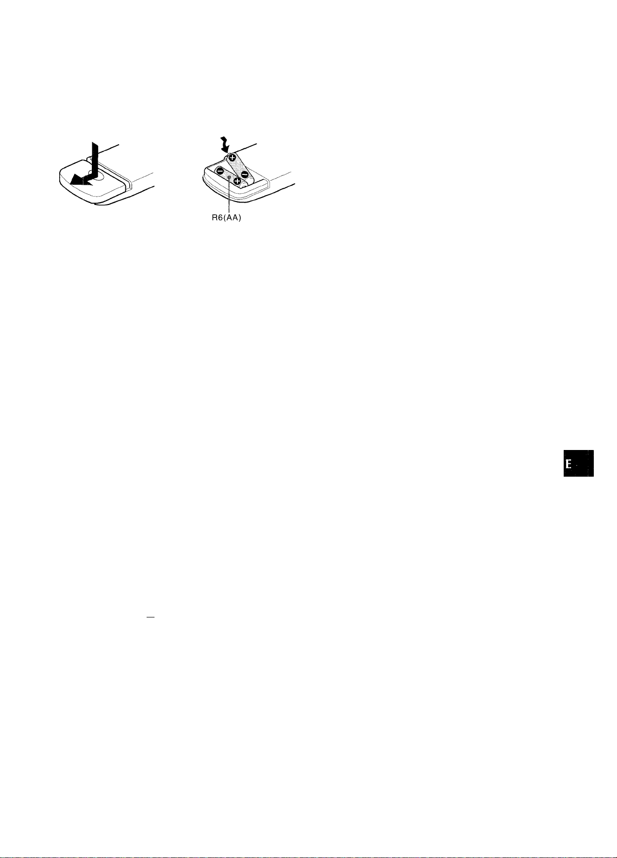
Inserting batteries
Detach the battery cover on the rear of the remote control and
insert two R6 (size AA) batteries.
c
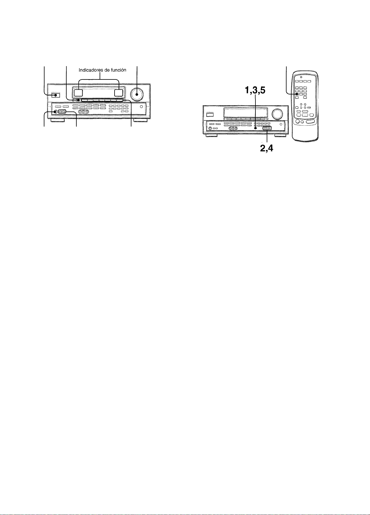
FUNCTION button
Each time this button is pressed, the sound source changes
FM (or AM)=» -» V3-> V2--» VI^CD-» AUX-i^ PHONO
cyclically.
a): Either band, which you have tuned in tor the last time, comes on.
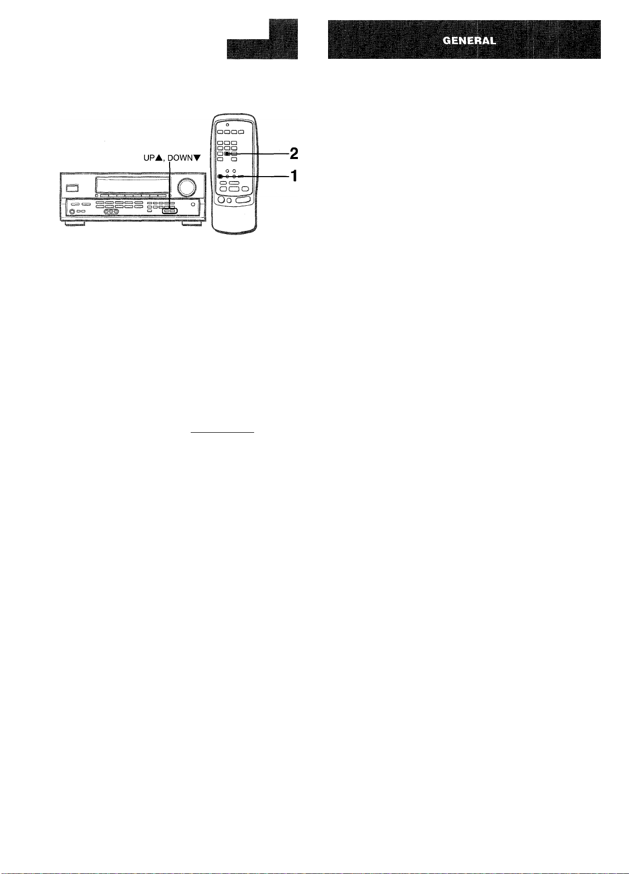
TUNER PRESET/SURROUND buttons
Tune in the station which has been preset on the receiver.
To go to a higher preset number, press the UP^W button. To
go to a lower preset number, press the DOWNW<( button.
This button is also used when adjusting the speakers level
balance of the DSP, Dolby Pro Logic or 5.1 CH mode.
t/i
2
:
O
<:
oc;
<
a.
lit
a:
Q.
When to replace the batteries
The maximum operational distance between the remote control
and the sensor on the unit should be approximately 5 meters
(16 feet). When this distance decreases, replace the batteries
with new ones.
Using the remote control
The instructions in this manual refer mainly to the buttons on the
main unit. Buttons on the remote control with the same names
as those on the main unit can be used as well.
• If the unit is not going to be used for an extended period of
time, remove the batteries to prevent possible electrolyte
leakage.
• The remote control may not operate correctly when:
- The line of sight between the remote control and the remote
sensor in the display window is exposed to intense light, such
as direct sunlight.
- Other remote controls are used nearby (those of television,
etc.)
Remote control operation
This remote control system allows you to operate other external
equipment besides the AIWA receiver. For details of the remote
control operation for other external equipment, see “REMOTE
CONTROL” on page 16.
Hereupon, it is explained how to operate the Aiwa receiver.
It is not necessary to press the AIWA RECEIVER button each
time you operate the Aiwa receiver unless another mode has
already been set. (See “REMOTE CONTROL” on page 16.)
If the receiver cannot be operated with the remote control
Follow the steps below with the remote control.
1 Press the AIWA RECEIVER button. 2 Press and hold the SET UP button for about 2.5
seconds.
The indicator on the top of the remote control blinks twice
while pressing the button.
3 Press the DIGIT buttons in the order of “4,” “0”
and “6.”
RECEIVER
AIWA
RECEIVER
MUTE
POWER
FUNCTION
KEY
TUNER PRESET/
SURROUND
VOLUME
1 Press the AiWA RECEiVER button to set the
remote controi to the Aiwa receiver mode.
2 Preaa one of the buttons indicsted above.
ENGLISH<SH 6
Page 8
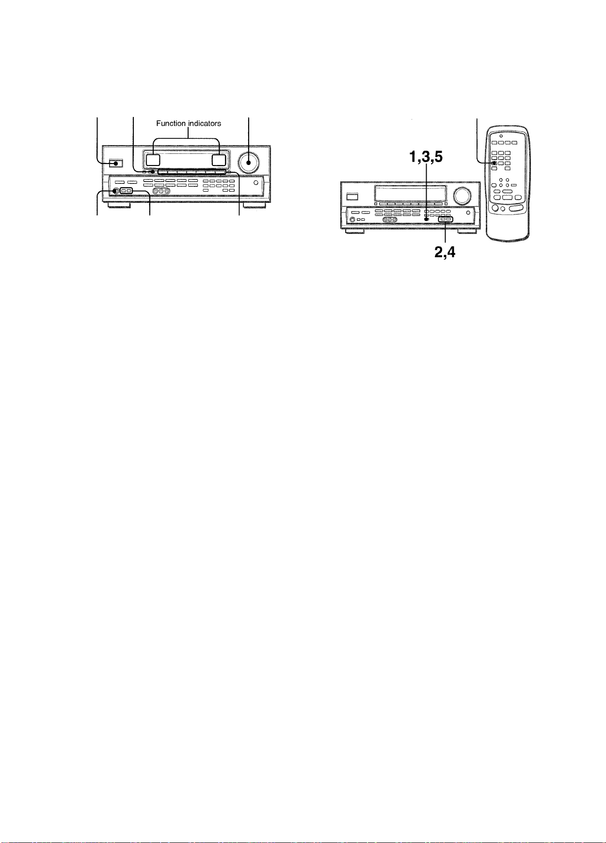
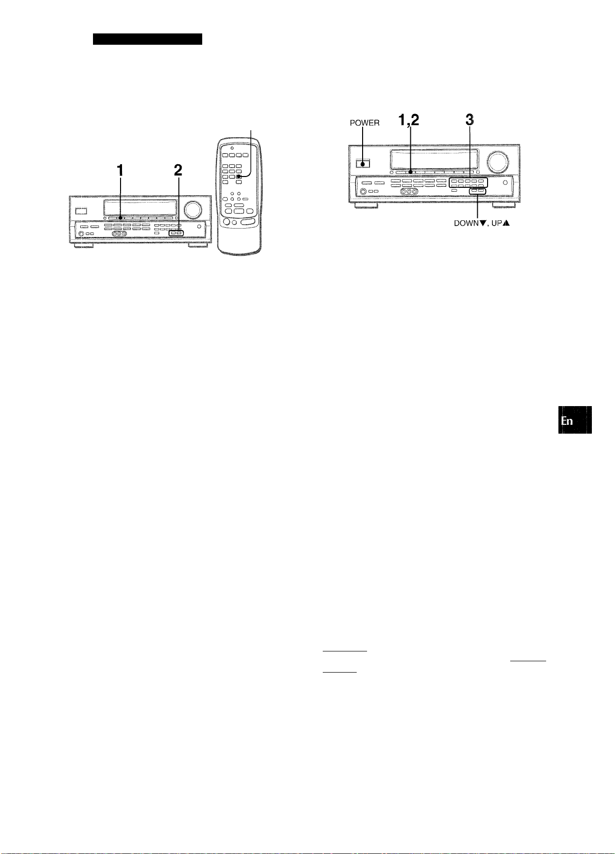
BEFORE OPERATION SEniNG THE CLOCK
POWER
PHONES FRONT SPEAKERS A, B Function
TAPE MONITOR
VOLUME
buttons
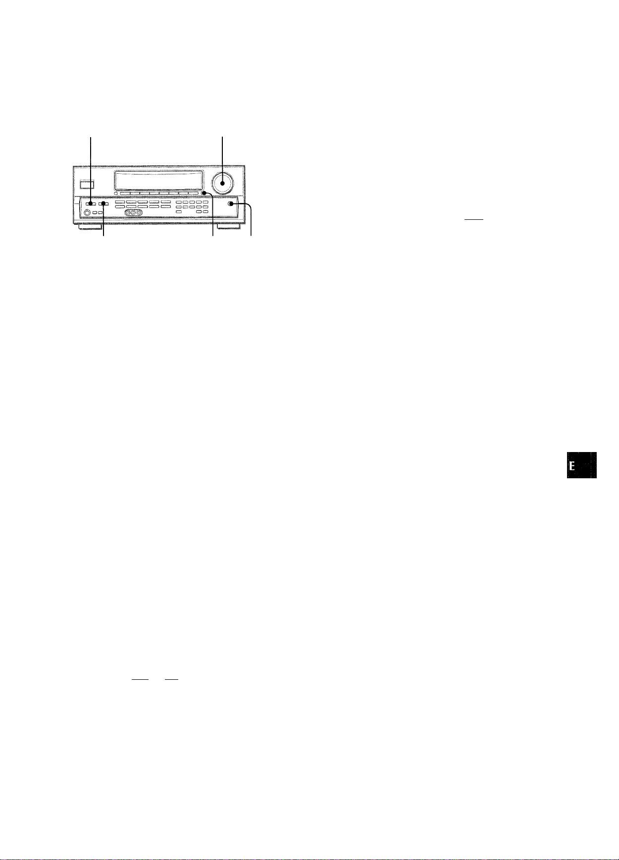
To turn the unit on
Press one of the function buttons (TUNER, PHONO,
AUX, CD, VIDEO 1/5.1 CH, VIDEO 2 or VIDEO 3) or
the TAPE MONITOR button.
When pressing the TUNER button, the previously tuned
station is received (Direct Play Function).
The POWER button is also available.
Operation is possible after four seconds, while the VOL
(volume) level or function name is displayed one after the
other and the selected function indicator flashes.
To select the front speaker system
To use speaker system A: Set the FRONT SPEAKERS A button
to *ON.
To use speaker system B; Set the FRONT SPEAKERS B button
to .»ON.
To use both speaker systems: Set both the buttons to »ON.
Set the button(s) to J.OFF to turn off the speaker system(s).
CLOCK
When the AC cord is connected for the first time, the clock on
the display flashes.
Set the time as follows while the power is off.
1 Press the SET button.
The hour flashes.
2 Press the DOWNT or UPA button to designate
the hour.
3 Press the SET button to set the hour.
The hour stops flashing and the minute starts flashing.
As the front speaker systems A and B are connected in series:
- The sound will be slightly decreased when using both speaker
systems
- No sound can be heard if the FRONT SPEAKERS A and B
buttons are set to »ON when only one speaker system is
connected
Using the headphones
Connect headphones to the PHONES jack with a standard stereo
plug (06.3 mm, 1/4 inch). Be sure to set the FRONT SPEAKERS
A and B buttons to J.OFF. Otherwise sound is output from the
speakers.
The 5.1 CH function, Dolby Pro Logic or DSP system is
automatically canceled when the headphones are plugged in.
To turn the unit off, press the POWER button.
4 Press the DOWNT or UPA button to designate
the minute.
5 Press the SET button to set the minute.
The minute stops flashing on the display and the clock starts
from 00 second.
To correct the current time
Press the POWER button to turn the unit off. Press the SET
button and carry out steps 1 to 5 above.
To display the current time
Press the CLOCK button on the remote control. The clock is
displayed for 4 seconds.
To switch to the 24-hour standard
Press the POWER button while pressing the UPA or DOWNT
button while the current time is displayed.
Repeat the same procedure to restore the 12-hour standard.
If the clock display flashes while the power is off
This is caused by a power interruption. The current time needs
to be reset.
If power is interrupted for more than approximately 24 hours, all
settings stored in memory after purchase need to be reset.
7 ENGLISH
Page 9
A
I
CUSTOM AUDIO ADJUSTMENT
T-BASS
VOLUME CONTROL
Turn the VOLUME control on the unit, or press the VOLUME
buttons on the remote control.
The volume level is shown on the display for four seconds. It
can be adjusted between 0 and MAX (31). It flashes when being
set over the level 21.
The volume level remains memorized even after the power is
turned off. However, if the power is turned off when the volume
is set to more than 17, it is automatically set to 16 the next time
the power is turned on.
VOLUME
SUPER T-BASS SYSTEM
The T-BASS system enhances the realism of low-frequency
sound.
Press the T-BASS button.
Each time it is pressed, the level changes. Select one of the
three levels, or the off position to suit your preference.
»lliitnia-
(cancel)
Low-frequency sound may be distorted when the T-BASS system
is used for a disc or tape in which low-frequency sound is
originally emphasized. In this case, cancel the T-BASS system.
SOUND ADJUSTMENT DURING
RECORDING
The output volume and tone of the speakers or headphones
may be freely varied without affecting the level of the recordingi.
CO
::
o
flD
< O
CL (/}
LlJ
CC
CL
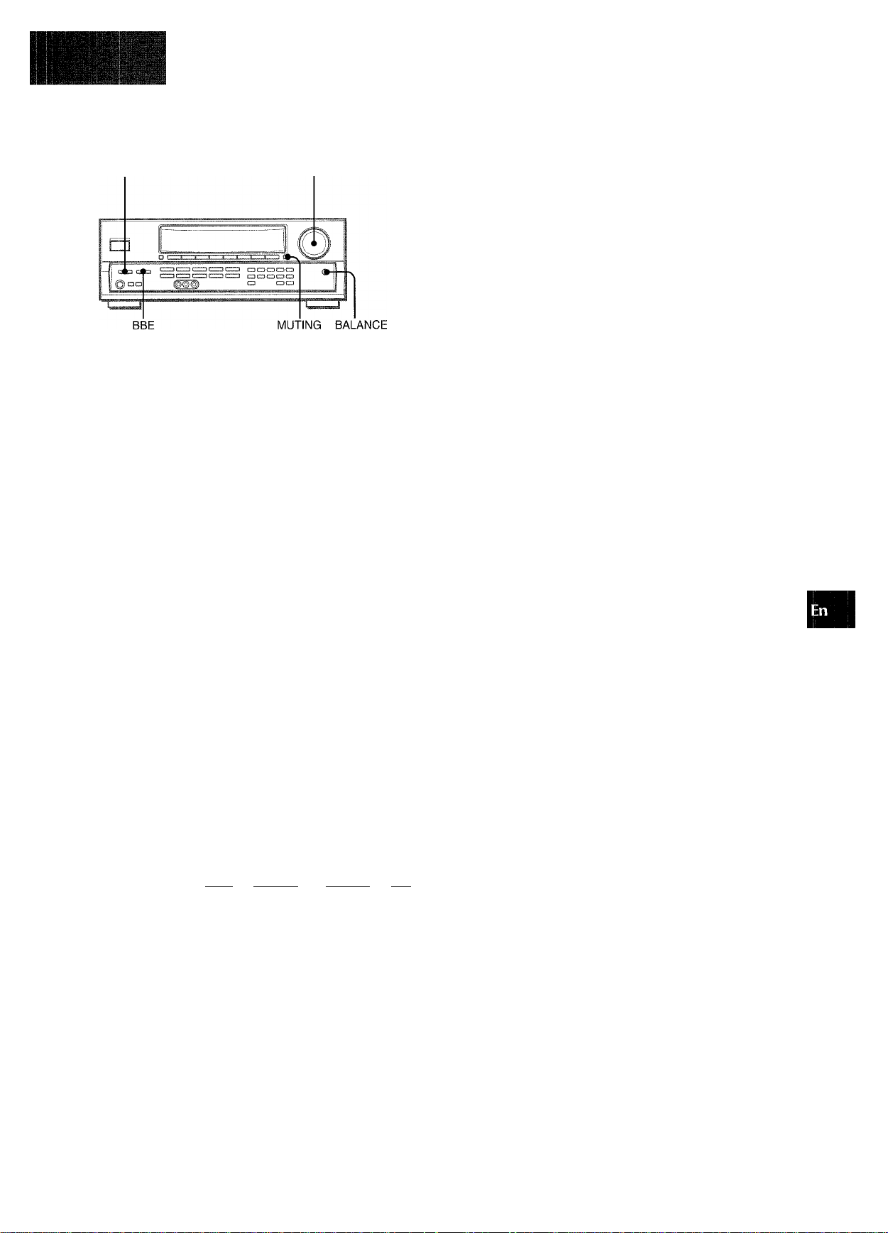
To adjust the left/right balance of the front speakers
Press the BALANCE button to display “L/R OdB”. Then press
the DOWNT or UPA button repeatedly within four seconds.
Note that the front speakers balance of the 5.1 CH and Dolby
Pro Logic modes is also changed.
To mute the sound temporarily
Press the MUTING button (-20 dB).
“MUTE ON” appears on the display for four seconds. While
muting the sound, the selected function indicator flashes. Press
the MUTING button again to restore the sound.
BBE SYSTEM
The BBE system enhances the clarity of high-frequency sound.
Press the BBE button.
Each time it is pressed, the level changes. Select one of the
three levels, or the off position to suit your preference.
»—».■asia—» 1515111—>■ 1515151 —»lilsrt-
I (cancel)
cr^i
■ The BBE system is automatically canceled:
- when the Dolby Pro Logic is turned on
- when the 5.1 CH function is selected
’ The BBE system cannot be turned on while the 5.1 CH function
is selected.
ENGLISH (5
Page 10
ELECTRONIC GRAPHIC EQUALIZER
GEQ
DSP SURROUND
MANUAL
DSP SELECT
n K ^10
1 <=:;cr3
This unit provides the following five different equalization modes.
ROCK: Powerful sound emphasizing treble and bass
POP: More presence in the vocals and midrange
JAZZ: Accented lower frequencies for jazz-type music
CLASSIC: Enriched sound with heavy bass and fine treble
BGM: Calm tone with suppressed bass and treble
Press one of the GEQ (Graphic Equalizer) buttons.
The selected mode name appears on the display for four
seconds, and the selected mode on the display Is enclosed with
parentheses.
CT3Cr3 1 C3CTC3C3trj ^
GEQ
MANUAL
SELECT
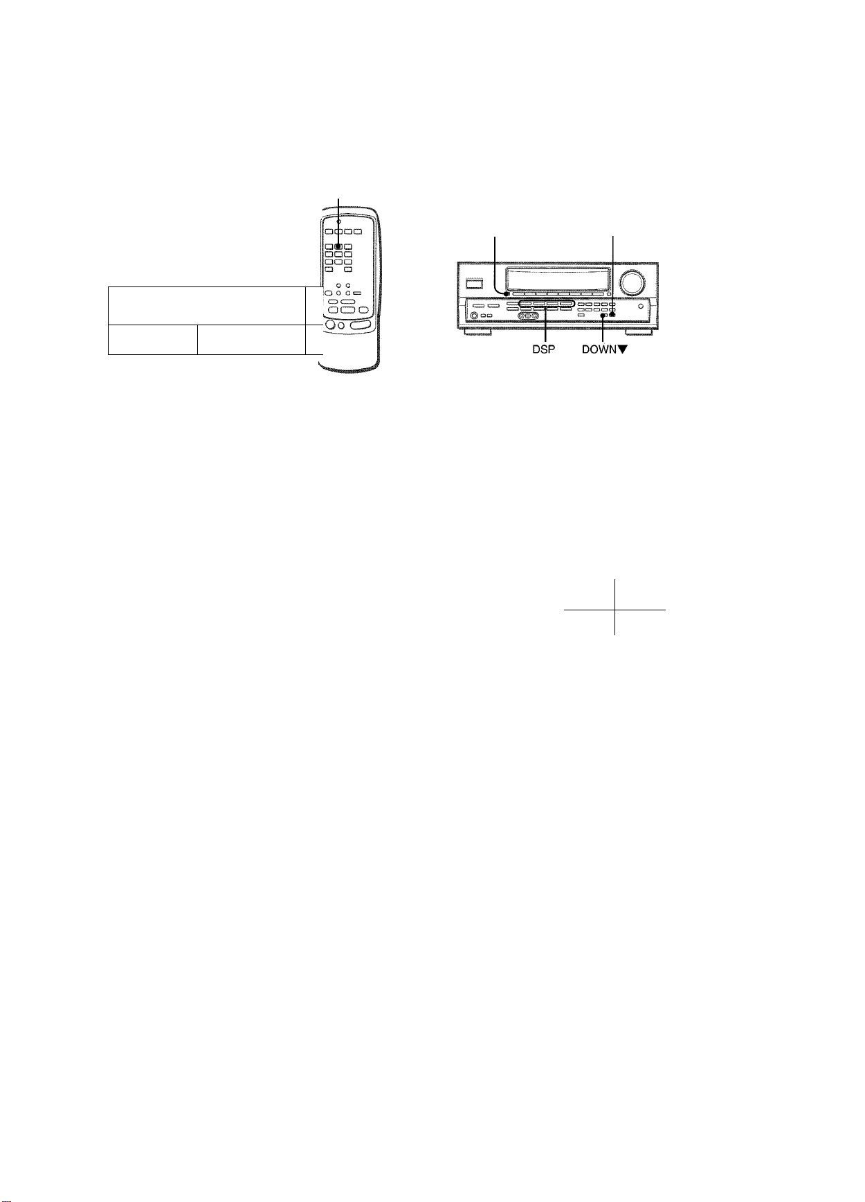
The DSP (Digital Signal Processor) surround circuits can recreate
the effect of sounds reflected from walls or ceilings, to obtain
the sound presence of real environments. There are four modes
with matching graphic equalization modes. Equalization modes
are selected automatically and can also be selected or turned
off to suit your preference.
UPA
□c 3
aa#
aaa
a a
o o
o|o o
c 3 CZD
(£(ZD
■DOWN
■UP^M
Press one of the DSP buttons (DANCE, LIVE, HALL or ARENA).
The selected mode name appears on the display for four
seconds, and the selected DSP and matching GEQ modes on
the display are enclosed with parentheses.
Selected DSP mode
.
(DANCE) 1 LIVE
(ROCK) 1 POP
I
Matching GEQ mode
\ J I-
HALL •ARENA
JAZZ... CLASSIC
■0:4
Selected mode
To cancel the selected mode
Press the selected button again. “GEQ OFF” appears on the
display.
To select with the remote control
Press the GEQ button repeatedly until the desired equalization
mode is displayed.
When the music source is monaural
Select LIVE to obtain a simulated stereo effect. When DANCE,
HALL or ARENA Is selected, no sound will be heard from the
surround speakers.
To cancel the selected mode
Press the selected button again. “DSP QFF” appears on the
display. Even if canceling the selected DSP mode, the matching
or selected GEQ mode still remains.
To select with the remote control
Press the DSP button repeatedly until the desired DSP mode Is
displayed.
To adjust the volume and balance of the surround
speakers
Press the MANUAL SELECT button twice or three times, while
the DSP system is turned on, to display “S-R OdB” (for right
surround speaker) or “S-L OdB” (for left surround speaker). Then
press the DQWNTor UPA button repeatedly within four
seconds.
Note that the surround speakers volume and balance of the 5.1
CH and Dolby Pro Logic modes are also changed.
' The DSP system is automatically canceled:
- when the Dolby Pro Logic Is turned on
- when the 5.1 CH function Is selected
' The DSP system cannot be turned on:
- while the 5.1 CH function Is selected
- while headphones are plugged In
9 ENGLISH
Page 11
Îtei-Sï-.-..?-
t’îivît.Æ:" -''- . '
^ ■ * ■ t
.....
............
V--
......
SELECTION OF AUDIO/VIDEO SOURCE
......
.......
.:
To change a displayed name for the VIDE:0 1/5.1 CH
button and VIDEO 2 button
When the VIDEO 1/5.1 CH button is pressed, VIDEO 1 is
displayed initially. It can be changed to DVD or MD.
With the power on, press the POWER button while pressing the
(/}
2:
o
VIDEO 1/5.1 CH button.
This VIDEO 1/5.1 CH button also works as the 5.1 CH (5.1
INPUT) function switch. While the selected function name
(VIDEO 1, DVD or MD) for the VIDEO 1/5.1 CH button is
displayed, press the button again. The function name will change
to “5.1 CH” and the source connected to the 5.1 INPUT terminals
is selected.
To resume, press the button again so that the selected function
So
CO
o
<
m
name is displayed.
The displayed name for VIDEO 2 button can be changed to
VIDEO 2, LDorTV; with the power on, press the POWER button
while pressing the VIDEO 2 button.
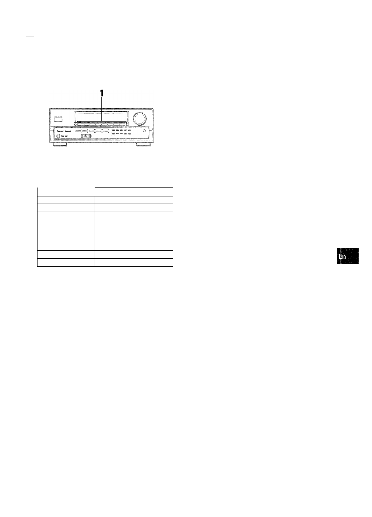
1 Select the program source.
Press one of the function buttons or the TAPE MONITOR
button.
To listen to or watch The button pressed
Tape
Radio
TAPE MONITOR
TUNER
Record PHONO
Television, etc. AUX
Compact disc
Video
CD
VIDEO 1/5.1 CH, VIDEO 2,
VIDEO 3
LD or Cable TV
VIDEO 2
MD or DVD VIDEO 1/5.1 CH
The function buttons to be pressed (except PHONO) depend
on the equipment connected to the input terminais on the
rear panel of the unit.
When using a turntable with a built-in equalizer amplifier, set the
switch of the equalizer amplifier to off. See the instructions of
the turntable for further information.
2 Start the selected program source. 3 Adjust the sound.
To adjust the sound level of the connected source
The input sensitivity level of each function (except the TUNER
and 5.1 CH functions) can be adjusted.
When the sound level of the connected source is higher or lower
than that of the TUNER, adjust it as follows.
1 Select the function to be adjusted.
Press the function button accordingly and play the source.
2 Press the UP A or DOWNT button repeatedly.
The level can be adjusted between -6dB (MIN) and +8dB (MAX)
in 2dB steps. Adjust the level so that the sound is output at the
same level as the TUNER.
•The input sensitivity level of the TUNEF^ or 5.1 CH function
cannot be adjusted.
• That of the TAPE MONITOR cannot be adjusted either.
Even if the TAPE MONITOR is selected and the TAPE
MONITOR indicator turns red, pressing the UPA or DOWNV
button will change the level of the function displayed on the
window.
About the video source to the monitor or TV
I
Selected VIDEO source
VI; VIDEO 1, V2: VIDEO 2, V3: VIDEO 3
The selected video source is indicated on the display and the
video signal through the MONITOR VIDEO OUT jack is output
on the TV.
ENGLISH 10
Page 12
TO PLAY A DVD RECORDED IN DOLBY
DIGITAL SURROUND
This receiver has the 5.1 INPUT connectors supporting Dolby
Digital decoder with the 5.1 ch output terminals. When a DVD
player that contains a Dolby Digital decoder is connected to the
receiver, you can enjoy theater-quality audio right in your home
when playing discs recorded in Dolby Digital Surround.
1 Press the VIDEO 1/5.1 CH button to select the
VIDEO 1 (DVD or MD) function.
2 Press the VIDEO 1/5.1 CH button again.
RECORDING AN AUDIO SOURCE
1 Select the program source to be recorded.
Press one of the function buttons.
“5.1 CH” appears on the display and the DVD player
connected to the 5.1 INPUT terminals Is selected as a source.
3 Start piaying the DVD recorded in Dolby Digital
Surround.
To resume the VIDE01, DVD (2 ch stereo) or MD function, press
the VIDEO 1/5.1 CH button again.
• The 5.1 CH function is automatically canceled and the VIDEO
1, DVD or MD function is selected;
- when the Dolby Pro Logic is turned on
- when headphones are plugged in
• The 5.1 CH function cannot be selected while headphones are
plugged in.
2 Set the tape deck or MD recorder to the recording
mode.
3 Start the selected program source.
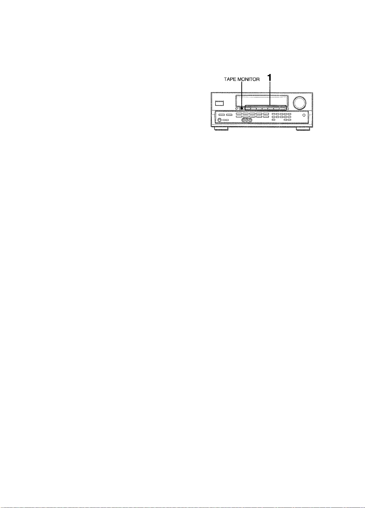
To monitor recorded sound during recording (when the connected tape deck is a three-head system)
Press the TAPE MONITOR button. ‘TAPE ON” appears on the
display for four seconds, and then the source name selected in
step 1 comes back on. To cancel the tape monitor, press it again
so that “TAPE OFF” appears.
• Any sound control system has no effect on recording (see page
8).
•Input sound through the 5.1 INPUT terminals cannot be
recorded. When recording the sound from the DVD player,
connect the AUDIO OUT (DOWN MIXING) terminals of the DVD
player to the VIDEO 1/DVD/MD AUDIO IN terminals of the unit.
• When recording sources by the MD recorder connected to the
VIDEO 1/DVD/MD AUDIO OUT terminals, select the source
after pressing the VIDEO 2 or VIDEO 3 button (V2 or V3 should
be displayed).
Recording cannot be done while the VI indication is displayed
on the window.
• Input sound from the tape deck connected to the TAPE
MONITOR IN terminals cannot be recorded.
11 ENGLISH
Page 13
RADIO RECEPTION
MANUAL TUNING
MONO
TUNER
1 Press the TUNER button repeatedly to select the
desired band.
The display changes to frequency indications after indicating
band and video source (V1, V2 or V3) for two seconds.
When the TUNER button is pressed while the power is off,
the power is turned on directly.
cr
FM
-------
► AM •
n
DIRECT TUNING
When you know the frequency of the desired station, you can
tune in directly to the station.
1 Press the TUNER button to select a band.
2 Press the TUNER button and hold it down until
“
....
’’flashes on the display (DirectTuning Mode).
c5g
LIJ
o2
ci5°
«I **
cn“:
UJ
Press the UPA or DOWNT button to select a station.
Each time the button is pressed, the frequency changes.
When a station is received, “TUNE” is displayed for two
seconds. During FM stereo reception, is displayed.
To search for a station quickly (Auto Search)
Keep the UPA or DOWNT button pressed until the tuner starts
searching for a station. After tuning in to a station, the search
stops.
To stop the Auto Search manually, press the UPA or DOWNT
button.
• The Auto Search may not stop at stations with very weak
signals.
When an FM stereo broadcast contains noise
Press the MONO TUNER button on the remote control so that
“MONO” appears on the display.
Noise is reduced, although reception is monaural.
MONO
I
3 Press the appropriate numbered buttons to tune
in to the desired station.
Example:
To tune in to 106.50 MHz, press 1,0, 6, 5 and 0 buttons.
To tune in to 95.20 MHz, press 9, 5, 2 and 0 buttons.
To cancel the Direct tuning mode
Press the UPA or DOWNT button.
' When entering a frequency out of tuning range, the value
flashes for two seconds and then goes off. Check the frequency
and repeat step 3 correctly.
■ When entering a frequency not covered by the tuning interval,
the value is automatically rounded up or down to the closest
one covered by it.
' The DIGIT buttons on the remote control can not be used when
tuning in to the desired station.
To change the AM tuning interval
The default setting of the AM tuning interval is 10 kHz/step. If
you use this unit in an area where the frequency allocation
system is 9 kHz/step, change the tuning interval.
Hold down the TUNER button and press the POV^/ER button
immediately. Note that the unit is set to the Direct Tuning mode
if the TUNER button is pressed and held down for about half
a second.
To reset the interval, repeat this procedure.
To restore stereo reception, press the button so that “MONO”
disappears.
ENGLISH 12
Page 14
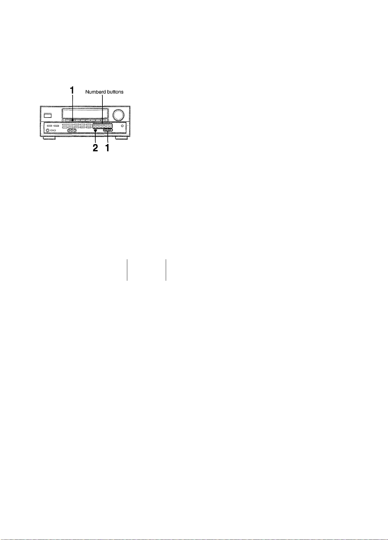
PRESEniNG STATIONS
aaa
aaa
aoc3
Q Q
O O
C O O =
CDdD
®CD(
0C3
The unit can store a total of 32 preset stations. When a station is
stored, a preset number is assigned to the station. Use the preset
number to tune in to a preset station directly.
1 Press the TUNER button to select the band, and
press the UPA or DOWNT button to select a
station. Direct tuning is also available.
■DOWN
■UPW
PRESET NUMBER TUNING
1 Press the TUNER button to select a band. 2 Press the numbered buttons to select a preset
number.
Example:
To select preset number 25, press 2 and 5.
To select preset number 7, press 0 and 7.
To clear a preset station
Select the preset number of the station to be cleared. Then, press
the SET button, and press the SET button again within four
seconds.
The preset numbers of all other stations in the band with higher
numbers are decreased by one.
When using the remote controi
Press UPWH or DOWNK< button to select a preset number.
The DIGIT buttons on the remote control can not be used when
selecting a preset number.
2 Press the SET button to store the station.
A preset number assigned to the station, beginning from 1 in
consecutive order for each band, flashes in the display for
two seconds.
1C BGM
' I
3 Repeat steps 1 and 2.
No more stations will be stored if a total of 32 stations have
already been stored for all the bands.
When the AM tuning interval is changed, all preset stations are
cleared. The preset stations have to be set again.
13
ENGLISH
Page 15
This unit is equipped with the Doiby Pro Logic decoder and also
supports the Dolby Digital decoder with the 5.1 ch output
terminals.
The unit and the center and surround speakers (standard) assure
full-scale home theater sound. When playing back discs or video
software that have been recorded in Dolby Pro Logic or Dolby
Digital Surround, astonishingly realistic sound surrounds the
listener to create a new level of audio/visual entertainment.
Independent control of the five channels allows the listener to
enjoy the same type of sound reproduction experienced in movie
theaters. Voices are reproduced in the front and center sound
field, while ambient sounds like cars and crowds are reproduced
on all sides of the listener for an incredibly lifelike audio/video
experience. Please read the following carefully to “tune” the
system’s output to match the characteristics of your listening
space.
Check the following:
• Before enjoying the DOLBY SURROUND sound, adjust the
proper balance of the speaker sound levels (see page 15).
• Make sure the speakers are properly connected and positioned
(see pages 3, 4 and 5).
• Make sure the TV set and video unit are properly connected
(see page 3).
• Make sure the disc and video tape, etc., support Dolby Pro
Logic or Dolby Digital Surround.
TO SELECT A DOLBY PRO LOGIC MODE
1,2
.X.—,,—, ciDczpcrDczzic;
I ^^ CZI3CTS aaaczia
|@Do ®Sp
Press the DOLBY SURROUND button repeatedly
to select the appropriate mode.
When selecting the DOLBY PRO LOGIC or 3 STEREO mode,
the indicator lights up, and the selected mode name runs
through on the display. Each time the button is pressed, the
mode changes as shown below.
DOLBY PRO LOGIC
c
DOLBY PRO LOGIC OFF(cancel) <*—”
------
► 3 STEREO
OK
Lu
is:
o _i
<o
c: a
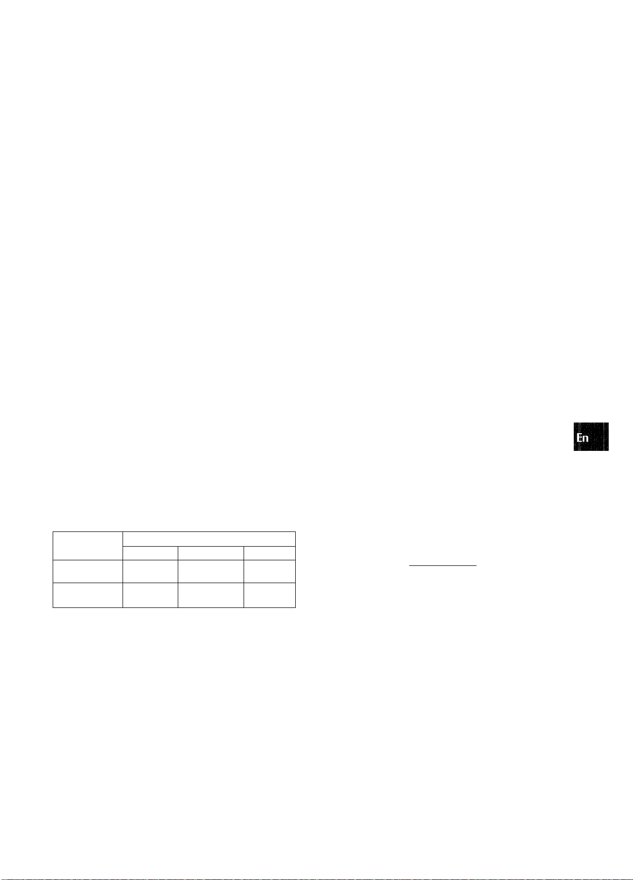
SELECTING DOLBY PRO LOGIC
The optimal Dolby Pro Logic mode depends on the type and
placement of the speakers. It is recommended that the optional
Aiwa speakers should be used for all channels, for example, the
SX-R2500 for surround speakers, the SX-C2500 for a center
speaker and the SX-AV2500 for front speakers. Check your
current type and placement of the speakers and select the
recommended Dolby Pro Logic mode accordingly.
The recommended mode
Center speaker
Larger-size
Surround speaker
(Rear speaker)
No surround
speaker
DOLBY PRO
LOGIC-WIDE
3 STEREO
WIDE
PHANTOM mode: Select this mode when the center speaker is
not connected. All center channel signals are redistributed to
the left and right channel speakers.
3 STEREO mode: Select this mode when the surround speakers
are not connected.
Smaller-size No speaker
DOLBY PRO
LOGIC-NORMAL
3 STEREO
NORMAL
PHANTOM
- '
Press the DOLBY SURROUND button again and
hold it down until the center speaker mode to be
selected appears.
When selecting the DOLBY PRO LOGIC mode in step 1:
“NORMAL”, “WIDE” and “PHANTOM” appear in turn.
When selecting the 3 STEREO mode in step 1:
“NORMAL” and “WIDE” appear one after the other.
' Depending on the sound source or listening condition, surround
effect may not be obtained even when the Dolby Pro Logic is
set to on.
' The full Dolby Pro Logic effect cannot be obtained when using
the software without nni5ii-°Y5n°B°uM°l mark. In this case, use
the DSP surround system instead (see page 9).
' The Doiby Pro Logic system is automatically canceled:
- when the BBE or DSP system is turned on
- when the 5.1 CH function is selected
- when headphones are plugged in
’ The Dolby Pro Logic cannot be set to on while headphones
are plugged in.
ENGLISH 14
Page 16
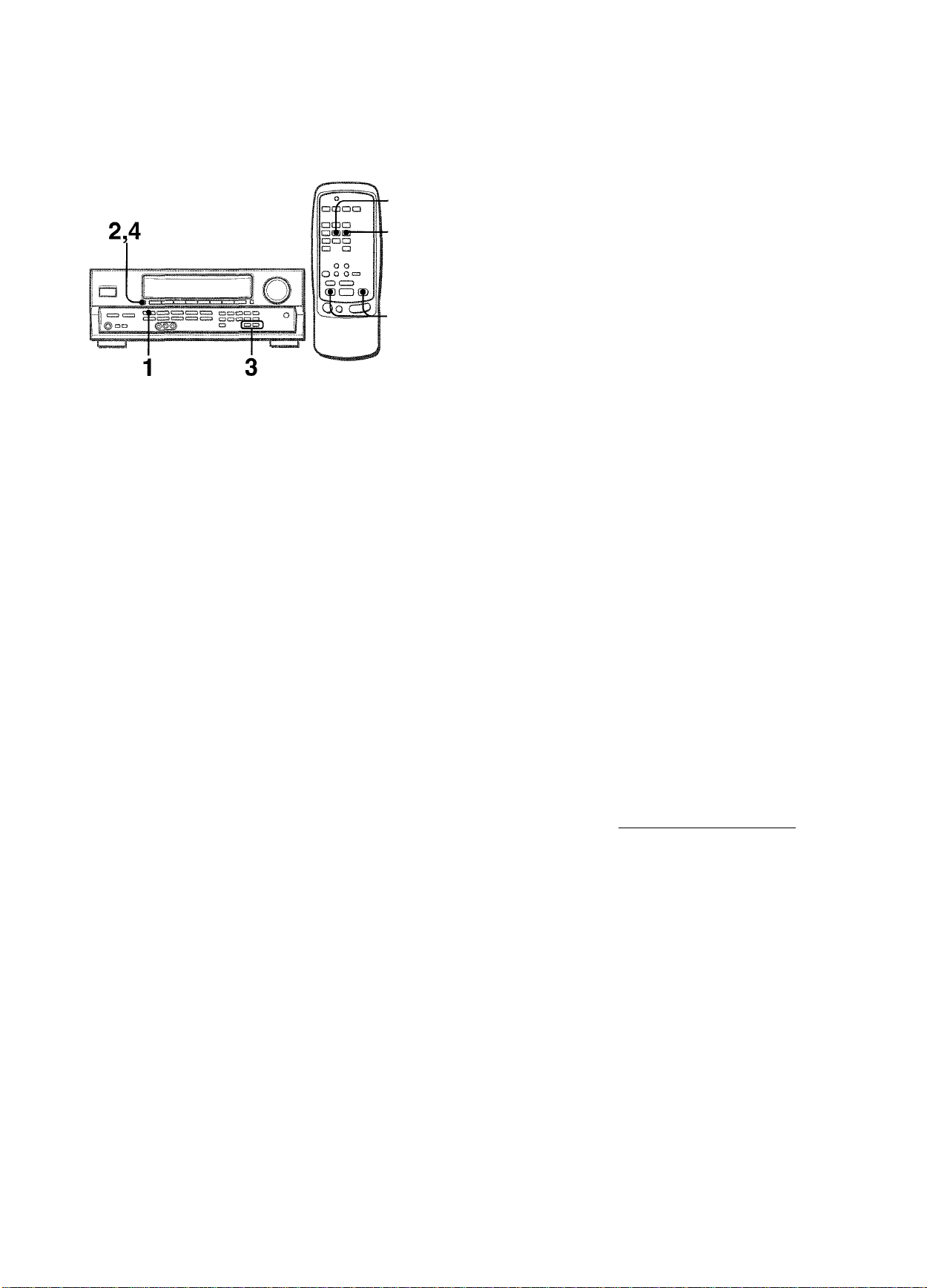
ADJUSTING SPEAKER LEVEL
BALANCE
1
2,4
■UPW
DOWN
Adjust the sound level of the center and surround
speakers.
While “CEN”, “S-L” or “S-R” flashes in the display, press the
UPA or DOWNT button so that the sound level of the center
or surround speakers matches that of the front speakers.
/ I \
The balance of the front speakers can be adjusted as well
while “L/R” is displayed.
4 Press the MANUAL SELECT button again to stop
the noise signai.
The unit is equipped with a built-in test signal generator called a
noise sequencer for easy balance adjustment of all five channels.
The sequencer outputs a noise signal that “travels” from channel
to channel, enabling the simple adjustment of sound level to
achieve the same apparent loudness, at your listening position,
from each channel.
1 Seiect the Doiby Pro Logic mode according to
your current type and placement of the speakers.
(See page 14.)
2 Press the MANUAL SELECT button and hold it
down for about two seconds until “L/R OdB”
appears.
pninQlci Ì dance uve hall arena
-—^ I ^ ROCK PO? JA2Z CLASSIS BQM
/ I \
A noise signal is sent to each channel in turn as follows:
DOLBY PRO LOGIC NORMAL or WIDE mode
L/R OdB (Left front speaker)*^
I
CEN OdB (Center speaker)
I
L/R OdB (Right front speaker)*’
I
S-R OdB (Right surround speaker)*
S-L OdB (Left surround speaker)
I
___________________
DOLBY PRO LOGIC PHANTOM mode
L/R OdB*’-
S-L0dB*=^
r
3 STEREO NORMAL or WIDE mode
L/R OdB*’-
r
L/R OdB*
■S-R OdB*
■CENOdB-
■a
L/R OdB*
• The UP^M or DOWNK^ button on the remote control cannot
be used in step 3 when adjusting speakers balance with the
noise signals.
• When adjusting the speakers level balance of the Dolby Pro
Logic, those of the DSP and 5.1 CH modes are also changed.
About the channels
The left and right speakers create the stereo effect.
The center speaker helps achieve precise sound positioning
over a broad sound field.
The rear-mounted surround speakers enhance the “depth” of
the sound field.
To change the surround speakers delay time of the Dolby Pro Logic mode
The surround speakers reproduce sounds a split second after
the front speakers. The delay is initially set to 20 ms
(milliseconds).
To change this standard delay time, press the MANUAL SELECT
button repeatedly so that “SUR” is displayed. Then, press the
UPA or DOWNT button. Each time one of the buttons is
pressed, the delay time changes as shown below.
(->■15ms 20 ms ■<—> 30ms-*1
To adjust the speakers level balance while listening to the source (Dolby Pro Logic and 5.1 CH modes)
The speakers level balance can be changed after adjusting it
with the noise sequencer. The balance can be changed whenever
the Dolby Pro Logic system is turned on or the 5.1 CH function
is selected.
1 Play a disc or video software recorded in Dolby Pro Logic or
Dolby Digital Surround.
2 Press the MANUAL SELECT button repeatedly so that “L/R”,
“CEN”, “S-L” or "S-R” appears on the display.
3 Press the UPA or DOWNT button while the speaker name
to be adjusted is displayed.
In this case, the UP^M or DOWNM^ button on the remote
control can be used as well.
*1 ..p» flashes to indicate one of the front speakers from which
the noise signal is output.
The noise signal is output from the L and R surround speakers at
the same time.
15 ENGLISH
Page 17

OPERATING TV, CABLE TV, VCR AND CD PLAYER
You can control basic functions of a TV, CABLE TV, VCR and
CD player with this remote control.
TO ENTER THE ID CODE OF THE EXTERNAL EQUIPMENT
Indicator.
MODE SELECT ■
a
aacDa
□ QQ
Q) Q
p~51
qIq ol^^—
CZ) CID
QCDO
"^i
. DIGIT buttons
(0~9)
■ SET UP
Oo CZ)
To confirm the stored ID code
You can check the stored ID code by counting the indicator
blinking.
1 Press either the TV, CABLE, VCR or CD button.
For example, to check the stored code for CD player, press
CD.
2 Press and hold the SET UP button for about 2.5 seconds, 3 Press “9,” “9” and “0.” 4 Press “1,” and count the indicator blinks.
For example, in the case that the stored ID is “157.”
The indicator blinks once.
5 Press “2,” and count the indicator blinks.
The indicator blinks five times.
6 Press “3,” and count the indicator blinks.
The indicator blinks seven times.
TO CONTROL TV, CABLE TV, VCR AND CD
PLAYER
CHANNEL
-----
ft
■VOLUME
■ DIGIT buttons
(0~9) and ENTER
Q-l
zo
:3cc
o\=
ieO
:3 0
(.0 UJ
m O
..JS
Olu
ate
Before attempting to control them, be sure to enter the ID code
of the external equipment to the remote control as follows.
1 Confirm the code number of the external
equipment.
See the ID code list in the “APPENDIX” at the end of this
manual.
2 Press either the TV, CABLE, VCR or CD button in
the MODE SELECT area.
3 Press and hold the SET UP button for about 2.5
seconds.
Confirm that the indicator blinks twice while pressing the SET
UP button.
4 Press three DIGIT buttons which correspond to
the ID code of the external equipment.
For example, if your CD player is an AIWA unif, the required
ID code is 124 or 157. In this case, press the DIGIT buttons
in the order of “1,” “2” and “4” (or “1,” “5” and “7”).
After the third DIGIT button is pressed, the indicator blinks
twice indicating that the ID code is correct and is stored on
the remote control.
MODE SELECT •
VCR/CD
POWER ■
ll:Pause,H:Stop,
M^;Rewind,
►:Play,
►►I: Fast forward
1 Press any button in the MODE SELECT area (TV,
CABLE, VCR or CD).
The remote control is ready to operate the selected mode
equipment.
2 Press one of the buttons indicated above.
For the use of fhe 0-9 and the ENTER buttons, see the
instruction manual supplied with the unit to be controlled.
Other buttons indicated above have the same function which
you will find on the unit to be controlled.
’ Reenter the ID CODE of the external equipment after replacing
the batteries of the remote control.
■ If fhere are plural ID codes for external equipment in the
“APPENDIX,” try each number listed until you can control the
external equipment.
ENGLISH
16
Page 18
SEniNG THE SLEEP TIMER
The receiver can be automatically turned off at a specified time.
1 Press the AIWA RECEIVER button. 2 Press the SLEEP button.
CARE AND MAINTENANCE
Occasional care and maintenance of the unit is needed to
optimize the performance of your unit.
To clean the cabinet
Use a soft dry cloth.
If the surfaces are extremely dirty, use a soft cloth lightly
moistened with mild detergent solution. Do not use strong
solvents, such as alcohol, benzine or thinner as these could
damage the finish of the unit.
The unit will be turned off after about 60 minutes.
To specify the time until the power is turned off
Press the UPA or DOWNT button on the main unit repeatedly
within four seconds after step 2.
Each time the button is pressed, the time changes between 5
and 240 minutes in 5-minute steps.
Specified time
To check the time remaining untii the power is turned off
Press the SLEEP button once. The remaining time is displayed
for four seconds.
To cancel the sleep timer
Press the SLEEP button twice so that “SLEEP” on the display
disappears.
The UP^M or DOWNM^ button on the remote control cannot
be used to specify the time until the power is turned off. Use the
buttons on the main unit.
1 7 ENGLISH
Page 19

SPECIFICATIONS
FM tuner section
Tuning range 87.5 MHz to 108 MHz
Usable sensitivity 13.2 dBf
(IHF)
Antenna terminals 75 ohms (unbalanced)
AIVI tuner section
Tuning range
Usable sensitivity Antenna
Amplifier section
Power output [Stereo Mode]
Total harmonic
distortion
Inputs
Outputs
530 kHz to 1710 kHz (10 kHz step),
531 kHz to 1602 kHz (9 kHz step)
350 pV/m
Loop antenna
Front
130 watts per channel, Min. RMS at 8
ohms, from 40 Hz to 20 kHz, with no
more than 0.9% Total Harmonic
Distortion
[Dolby Pro Logic or 5.1 CH Mode]
Front
120 watts per channel, Min. RMS at 8
ohms, from 40 Hz to 20 kHz, with no
more than 0.9% Total Harmonic
Distortion
Rear (Surround)
60 watts per channel, Min. RMS at 8
ohms, 1 kHz, with no more than 0.9%
Total Harmonic Distortion
Center
120 watts, Min. RMS at 8 ohms, 1
kHz, with no more than 0.9% Total
Harmonic Distortion
0.08 % (85 W, 1 kHz, 8 ohms, Front)
AUDIO IN
PHONO: 2.5 mV, adjustable (47
kohms)
CD: 250 mV, adjustable (47
kohms)
TAPE MONITOR: 350 mV (47
kohms)
VIDEO 1/DVD/MD, VIDEO 2/LD/
TV, VIDEO 3, AUX: 250 mV,
adjustable (47 kohms)
5.1 INPUT
FRONT, CENTER: 560 mV (47
kohms)
SURROUND, SUB-WOOFER:
400 mV (47 kohms)
VIDEO IN: 1 Vp-p (75 ohms)
AUDIO OUT (REG OUT): 200 mV (1
kohm)
VIDEO OUT (MONITOR): 1 Vp-p (75
ohms)
SUPER WOOFER: 1,2 V
FRONT SPEAKERS IMP: 80/40
selectable (front speakers A and B):
with the SPEAKER IMPEDANCE
SELECTOR set to 40, accepts
speakers of 4 ohms,
with the SPEAKER IMPEDANCE
SELECTOR set to 80, accepts
speakers of 8 ohms or more.
SURROUND SPEAKERS IMP: 80
(surround speakers): accepts
speakers of 8 ohms or more
CENTER SPEAKER IMP: 80/40
selectable
with the SPEAKER IMPEDANCE
SELECTOR set to 40, accepts
speaker of 4 ohms,
with the SPEAKER IMPEDANCE
SELECTOR set to 80, accepts
speaker of 8 ohms or more.
PHONES (stereo jack): accepts
headphones of 32 ohms or more
Muting
-20 dB
General
Power requirements
Power consumption
Dimensions
(W X H X D)
Weight
Specifications and external appearance are subject to change
without notice.
uuu SYSTEM
The word “BBE” and the “BIBE symbol” are trademarks of BBE
Sound, Inc.
Under license from BBE sound, Inc.
DOLBY PRO LOGIC
Manufactured under license from Dolby Laboratories Licensing
Corporation.
“DOLBY” the double-D symbol □□ and ’’PRO LOGIC” are
trademarks of Dolby Laboratories Licensing Corporation.
120 VAC, 60 Hz
230 W
430 X 155 X 351 mm
(17x6 Vs x13Vs in.)
11.2 kg (24 lb 11 oz.)
ENGLISH 18
ss
UJ
:Z
UJ
Ü
Page 20

TROUBLESHOOTING GUIDE
PARTS INDEX
If the unit fails to perform as described in these Operating
Instructions, check the following guide.
GENERAL
There is no sound.
• Is the AC cord connected properly?
• Is there an incorrect connection? {-* page 3)
• There may be a short circuit in the speaker terminals.
Disconnect the AC cord, then correct the speaker
connections.
• Was an incorrect function button pressed?
• Are the FRONT SPEAKERS A and B buttons set correctly?
(-»page 7)
Sound is emitted from one speaker only.
• Is the BALANCE set appropriately?
• Is the other speaker disconnected?
Sound is heard at a very low volume.
• Has the MUTING button been pressed?
An erroneous display or a malfunction occurs.
-» Reset the unit as stated below.
TUNER SECTION
There is constant, wave-like static.
• Is the antenna connected properly? (-» page 5)
• Is the FM signal weak?
-► Connect an outdoor antenna.
The reception contains noise interference or the sound is
distorted.
• Is the system picking up external noise or multipath distortion?
-► Change the orientation of the antenna.
Move the unit away from other electrical appliances.
To reset
If an unusual condition in the display window or malfunction
occurs, reset the unit as follows.
1 Press the POWER button to turn off the power.
2 Press the POWER button while pressing the SET button.
Everything stored in memory after purchase is canceled.
If the power cannot be turned off in step 1 because of a
malfunction, reset by disconnecting the AC cord and carry out
step 2.
Instructions about each part on the unit or remote control are
indicated on the pages listed below.
Parts Pages
AIWA RECEIVER 6,17
AUX 7, 10
BALANCE 8
BBE 8
CD 7, 10
CLOCK
DOLBY SURROUND 14, 15
DOWN T (!◄◄)
DSP
FRONT SPEAKERS A, B 7
FUNCTION
GEO 9
MANUAL SELECT (TEST) 9, 15
MONO TUNER 12
MUTING, MUTE 8
PHONES
PHONO
POWER 7, 12
SET
SETUP 16
SLEEP
SPEAKER IMPEDANCE
SELECTOR
TAPE MONITOR 7, 10, 11
T-BASS 8
TUNER, BAND DIRECT 7, 10, 12, 13
TUNER PRESET/SURROUND
UP A (►►!) 7, 9, 10, 12, 13, 15, 17
VIDEO 1/5.1 CH 7, 10, 11
VIDEO 2
VIDEOS
VOLUME (V, 8, 16
7
7, 9, 10, 12, 13, 15, 17
9
6
7
7, 10
7, 13
17
4
6
7, 10
7, 10
19 ENGLISH
Page 21

Page 22

I
■ ^ 'i 7- “--3. -
s-. V".. .. v-.“';. ■■ -
ADVERTENCIA
PARA REDUCIR EL RIESGO DE INCENDIOS
O SACUDIDAS ELECTRICAS. NO EXPONGA
ESTE APARATO A LA LLUVIA NI A LA
HUMEDAD.
CAUTION
RISK OF ELECTRIC SHOCK
DO NOT OPEN
“PRECAUCIONiPARA REDUCIR EL RIESGO
DE QUE SE PRODUZCAN SACUDIDAS
ELECTRICAS, NO QUITE LA CUBIERTA
(O PANEL POSTERIOR).
EN EL INTERIOR NO HAY PIEZAS QUE
DEBA REPARAR EL USUARIO.
SOLICITE LAS REPARACIONES AL
PERSONAL DE SERVICIO CAPACITADO."
Explicación de ios símboios gráficos:
El símbolo del rayo con punta de flecha, en el
interior de un triángulo equilátero, tiene la
/m\ “tensiones peligrosas” sin aislar en el interior del
finalidad de avisar ai usuario de la presencia de
producto que podrían ser de suficiente magnitud
f \ como para constituir un riesgo de sacudida
eléctrica para las personas.
El signo de exclamación en el interior de un
triángulo equilátero tiene la finalidad de avisar al
usuario de la presencia de instrucciones de
operación y mantenimiento (reparación) en el
material impreso que acompaña al aparato.
PRECAUCIONES
Antes de utilizar la unidad, lea cuidadosa y completamente este
manual instrucciones. Guarde el manual de instrucciones para
futuras referencias. Todos los avisos y precauciones del manual
de instrucciones y de la unidad deberán seguirse estrictamente,
así como las sugerencias de seguridad indicadas a continuación.
Instalación
1 Agua y humedad — No utilice esta unidad cerca del agua,
como al lado de una bañera, un lavabo, una piscina, etc.
2 Calor — No utilice esta unidad cerca de fuentes térmicas,
como salidas de calefacción, estufas, ni demás aparatos que
generen calor.
Tampoco deberá someterse a temperaturas inferiores a 5°C
(41 °F) ni superiores a 35°C (95°F).
3 Superficie de montaje — Coloque la unidad sobre una
superficie plana y nivelada.
4 Ventilación — La unidad deberá colocarse donde tenga
espacio suficiente a su alrededor para asegurar su ventilación
adecuada. Deje un espacio libre de 10 cm en la parte posterior
y superior de la unidad, y de 5 cm a cada lado.
- No la coloque sobre una cama, una alfombra, ni nada similar
que pueda bloquear las aberturas de ventilación.
- No la instale en una librería, un armario, ni un bastidor
cerrado, donde la ventilación podría ser deficiente.
5 Entrada de objetos y líquidos — Tenga cuidado de que en
el interior de la unidad no entren objetos pequeños ni líquidos
a través de las aberturas de ventilación.
6 Carritos y estantes — Cuando haya colocado o montado la
unidad sobre un estante o un carrito,
deberá moverla con cuidado.
Las paradas repentinas, la fuerza
excesiva, o las superficies desiguales
podrían causar el vuelco o la caída de la
combinación de la unidad y el carrito.
7 Montaje en una pared o en el techo — La unidad no deberá
montarse en una pared ni en el techo, a menos que se
especifique en el manual de instrucciones.
Anotación del propietario
Para su conveniencia, anote el número de modelo y el número
de serie (los encontrará en el panel trasero de su aparato) en el
espacio suministrado más abajo. Menciónelos cuando se ponga
en contacto con su concesionario Aiwa en caso de tener
dificultades.
N.° de modelo
AV-D50
N.° de serie (N.° de lote)
Energía eléctrica
1 Fuentes de alimentación — Conecte esta unidad solamente
a las fuentes de alimentación especificadas en las
instrucciones de manejo, y como está marcado en la unidad.
2 Polarización — Como medida de seguridad, algunas
unidades disponen de enchufes de alimentación de CA
polarizados que solamente podrán insertarse de una forma
en el tomacorriente de la red. Si es difícil o imposible insertar
el enchufe de alimentación de CA en un tomacorriente de la
red, dele la vuelta e inténtelo de nuevo. Si sigue sin poder
insertarse bien, llame a un técnico de servicio cualificado para
que reemplace el tomacorriente. para evitar anular la función
de seguridad dei enchufe polarizado, no lo inserte a la fuerza
en un tomacorriente.
3 Cable de alimentación de CA
- Para desconectar el cable de alimentación, tire del enchufe
de CA. No tire del propio cable.
- No tome nunca el cable de alimentación de CA con las
manos húmedas, ya que esto podría resultar en incendios
o descargas eléctricas.
- No pise el cable de alimentación ni io pille con objetos
colocados encima o contra él, ya que podrían producirse
incendios o descargas eléctricas.
- Evite sobrecargar los tomacorrientes y los cables
prolongadores por encima de su capacidad, ya que esto
podría resultar en incendios o descargas eléctricas.
1 ESPAÑOL
Page 23

4 Cable prolongador — Para evitar descargas eléctricas, no
utilice el enchufe de alimentación de CA polarizado con un
cable prolongador ni tomacorriente a menos que el enchufe
pueda insertarse completamente a fin de evitar que sus
cuchillas queden al descubierto.
5 Períodos sin utilización — Cuando no vaya a utilizar la
unidad durante varios meses, desenchufe el cable de
alimentación de CA del tomacorriente de la red. Cuando el
cable de alimentación estás enchufado, circulará una
pequeña corriente por la unidad, incluso aunque la
alimentación esté desconectada.
Antena exterior
1 Líncías eléctricas — Cuando conecte una antena exterior,
cerciórese de que esté alejada de las líneas eléctricas.
2 Puesta a tierra de la antena exterior — Cerciórese de que
el sistema de antena esté adecuadamente puesto a tierra
como medida de protección contra sobretensiones
inesperadas o la generación de electrostática. El artículo
810 del código National Electric Code, ANSI/NFPA70
proporciona información sobre la puesta a tierra adecuada
del mástil, la estructura de soporte, y la acometida a la unidad
de descarga de la entena, así como sobre ei tamaño de la
unidad de puesta a tierra, la conexión de los terminales de
puesta a tierra, y los requisitos de puesta a tierra de los
propios terminales.
Puesta a tierra de la antena según el Codigo Eléctrico Nacionai
CABLE DE BAJADA
DE LA ANTENA
UNiDAD DE DESCARGA
DE LA ANTENA
(NEC,SECCION 810-20)
CONDUCTORES DE
PUESTA ATIERRA
(NEC,SECCION 810-21)
ABRAZADERAS DE
PUESTA ATIERRA
SISTEMA DE ELECTRODO DE PUESTA
A TIERRA DEL SERVICIO ELECTRICO
NEC(CODIGO ELECTRICO NACIONAL)
(NEC,ARTICULO 250,PARTE H)
INDICE
PRECAUCIONES
PREPARATIVOS
CONEXIONES................................................................... 3
ANTES DE LA OPERACION
PUESTA EN HORA DEL RELOJ
SONIDO
___________________________________
AJUSTE DEL SONIDO A SU GUSTO...............................8
ECUALIZADOR GRAFICO ELECTRONICO.....................9
SONIDO PERIMETRICO DEL PROCESADOR DE
SEÑAL DIGITAL
OPERACIONES BASICAS
SELECCION DE UNA FUENTE DE AUDIO/VIDEO
GRABACION DE UNA FUENTE DE AUDIO
ESCUCHA DE LA RADIO
SINTONIA MANUAL........................................................12
SINTONIA DIRECTA...................................................... 12
MEMORIZACION DE EMISORAS
DOLBY SURROUND
SELECCION DE DOLBY PRO LOGIC
AJUSTE DEL EQUILIBRIO DEL NIVEL
ENTRE ALTAVOCES..................................................
CONTROLADOR REMOTO
OPERACION DE UN TELEVISOR, SISTEMA DE
CABLEVISION, VIDEOGRABADORA, Y
REPRODUCTOR DE DISCOS COMPACTOS
..............................................................
____________________________
.............................................
.....................................
...........................................................
____________________
...................
_____________________
.................................
_________________________
..........................
.
...........
.........
1
7
7
9
10
11
13
14
15
16
Mantenimiento
Limpie ia unidad soiamente como se recomienda en ei manuai
de instrucciones.
Daños que requieren reparación
Haga que ia unidad sea revisada por un técnico de servicio
cuaiificado si:
- se ha dañado ei cabie de aiimentación o ei enchufe de CA.
- en ei interior de ia unidad han entrado objetos o iíquidos.
- ia unidad ha estado expuesta a ia iiuvia o al agua.
- la unidad parece no funcionar normalmente.
- la unidad presenta un cambio notable en su rendimiento.
- la unidad ha caído, o se ha dañado su caja.
NO INTENTE REPARAR USTED MISMO LA UNIDAD.
Compruebe su unidad y accesorios
Receptor estéreo AV-D50 Controlador remoto
■.»1
Antena de FM
Antena de AM
TEMPORIZADOR
____________________________
PROGRAMACION DEL TEMPORIZADOR
CRONODESCONECTADOR.......................................
17
GENERALIDADES___________________________
CUIDADOS Y MANTENIMIENTO.................................. 17
ESPECIFICACIONES.................................................
GUIA PARA LA SOLUCION DE PROBLEMAS....
.....
..........
18
19
INDICE DE LAS PARTES.............................................. 19
APÉNDICE
CODIGOS DE IDENTIFICACION PARA TELEVISION .
CÓDIGOS DE IDENTIFICACIÓN PARA
CABLEVISIÓN........................................................
CÓDIGOS DE IDENTIFICACIÓN PARA
VIDEOGRABADORAS
...........................................
CÓDIGOS DE IDENTIFICACIÓN PARA
REPRODUCTORES DE DISCOS COMPACTOS ...
. A-1
.A 2
.A-3
.A-4
Manual de instrucciones, etc.
ESPAÑOL.
Page 24
PREPARATIVOS
CONEXIONES
Antes de conectar el cable de alimentación de CA
La tensión nominal de su unidad indicada en ei panei posterior
de su unidad es de 120 V CA. Compruebe si esta tensión
coincide con ia de la red local.
IMPORTANTE
Conecte primero los altavoces, las antenas, y todos los demás
equipos externos. Después conecte el cable de alimentación
de CA.
Cerciórese de conectar el terminal VIDEO OUT de un reproductor de
discos DVD directamente a un televisor, no a través de esta unidad. De
lo contrario, es posible que aparezca ruido en las imágenes cuando
reproduzca discos DVD protegidos contra copia.
El sonido de entrada a través de los terminales 5.1 INPUT no podrá
grabarse. Cuando desee grabar sonido de un reproductor de discos
DVD, conecte los terminales AUDIO OUT (DOWN MIXING) del
reproductor de discos DVD a los terminales VIDEO 1/DVD/MD AUDIO
IN de la unidad.
Para conectar a un equipo de vídeo monoaural, utilice un cable conectar
de estéreo-monoaural (no suministrado).
CONEXION DE EQUIPOS
Las clavijas de ios cabies conectares y las tomas están
codificadas en coior de la forma siguiente:
Clavijas y tomas rojas; Para ei canai derecho de señaies de
audio
Clavijas y tomas blancas: Para el canal izquierdo de señaies de
audio
Clavijas y tomas amarilias: Para señaies de vídeo
NOTA
Inserte las clavijas de los cables conectores firmemente en las
tomas. Las conexiones flojas podrían producir zumbidos u otras
interferencias de ruido.
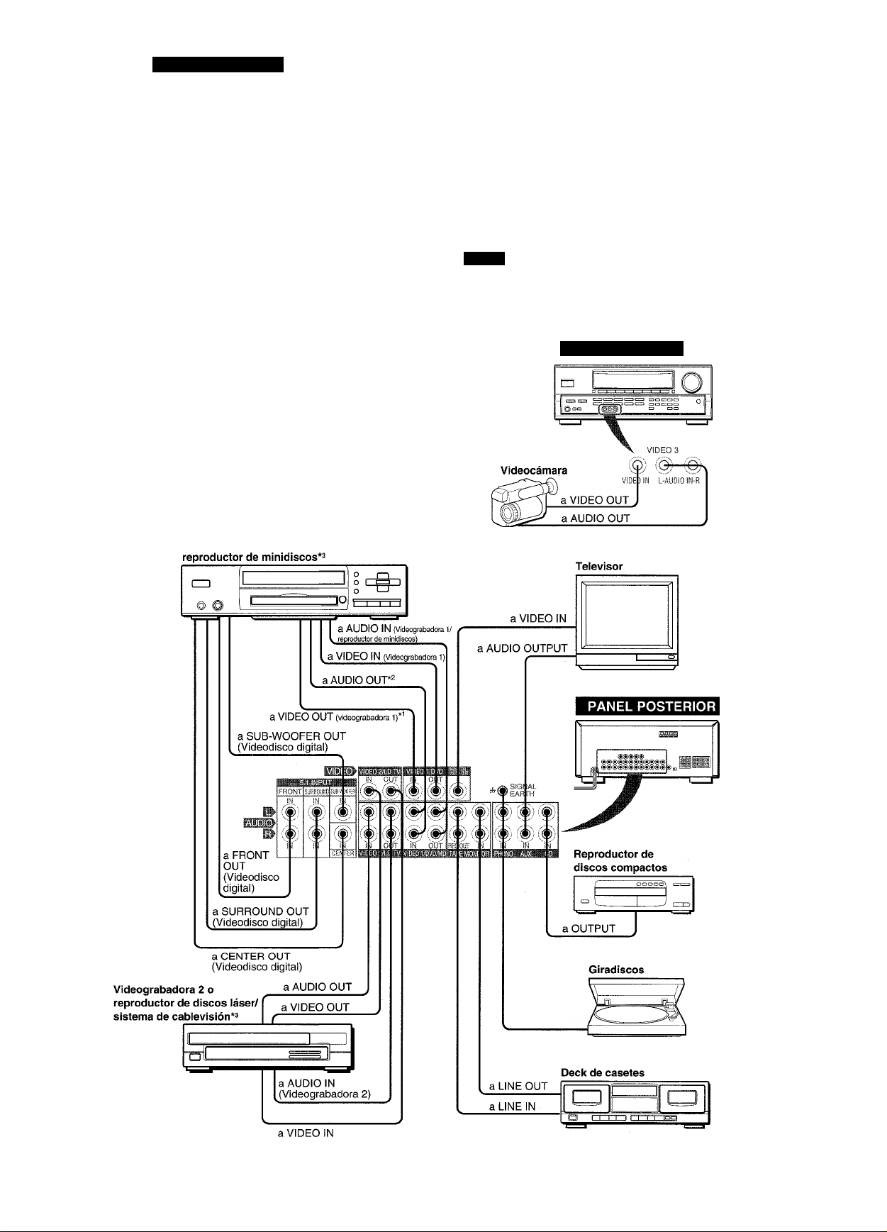
PANEL FRONTAL
Reproductor de discos DVD o videograbadora 1/
3 ESPAÑOL
(Videograbadora 2)
Page 25
® y (D de ia ilustración corresponden a los detalles siguientes.
(2)Antena de AM (2)Antena de FM
©Sistema de altavoces A ©Sistema de altavoces EÎ
(O
O
>
Œ
2
lU
cr
QL
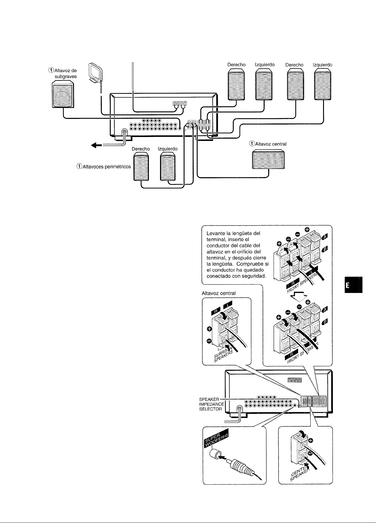
CONEXION DE LOS ALTAVOCES (5)
Terminales para altavoces
Conecte los altavoces delanteros (sistema A y/B), un altavoz
central, y altavoces perimétricos a los terminales para altavoces
correspondientes de la unidad.
- los cable de los altavoces delanteros a los terminales FRONT
SPEAKERS
- el cable del altavoz central a los terminales CENTER SPEAKER
- los cables de los altavoces perimétricos a los terminales
SURROUND SPEAKERS
- para obtener graves más potentes, el cable del altavoz de
subgraves (con amplificador incorporado, TS-W35, etc. Aiwa)
a la toma SUPER WOOFER <1.
Impetílancia de los altavoces
• Altavoces delanteros y central
Utilice altavoces de la misma impedancia para los delanteros y
el central.
El selector SPEAKER IMPEDANCE SELECTOR del panel
posterior deberá ponerse en la posición correspondiente al valor
de impedancia de los altavoces delanteros y central.
Cuando utilice altavoces de 4 ohmios, ponga el selector en
IMP:4£2. Cuando utilice altavoces de 8 ohmios, ponga el selector
en IMP:8Í2. Antes de ajustar el selector, desenchufe el cable de
alimentación de CA.
• Altavoces perimétricos y altavoz de subgraves
El selector SPEAKER IMPEDANCE SELECTOR no afecta a los
terminales SURROUND SPEAKERS ni a la toma SUPER
WOOFER tt]. Para los altavoces perimétricos y el altavoz de
subgraves, utilice altavoces de 8 ohmios o más.
Altavoces delanteros
Conexión de los terminales + a +, y - a -
Para obtener el efecto acústico apropiado, los terminales de la
unidad y de los altavoces deberán conectarse con la polaridad
apropiada: los terminales + de la unidad deberán conectarse a
los terminales + de los altavoces (y - a -).
• Cerciórese de conectar correctamente los cables de ios
altavoces como se muestra en la columna de la derecha. La
conexión inapropiada podría causar cortocircuitos en los
terminales SPEAKER(S).
• No coloque objetos que generen magnetismo cerca de los
altavoces.
•
Altavoces perimétricos
Altavoz de subgraves
ESPAÑOL 4
Page 26
UBICACION DE LOS ALTAVOCES
Coloque los altavoces de forma que obtenga el máximo efecto
del sistema Dolby Digital Surround (5,1 CH), Dolby Pro Logic, o
efecto del DSP.
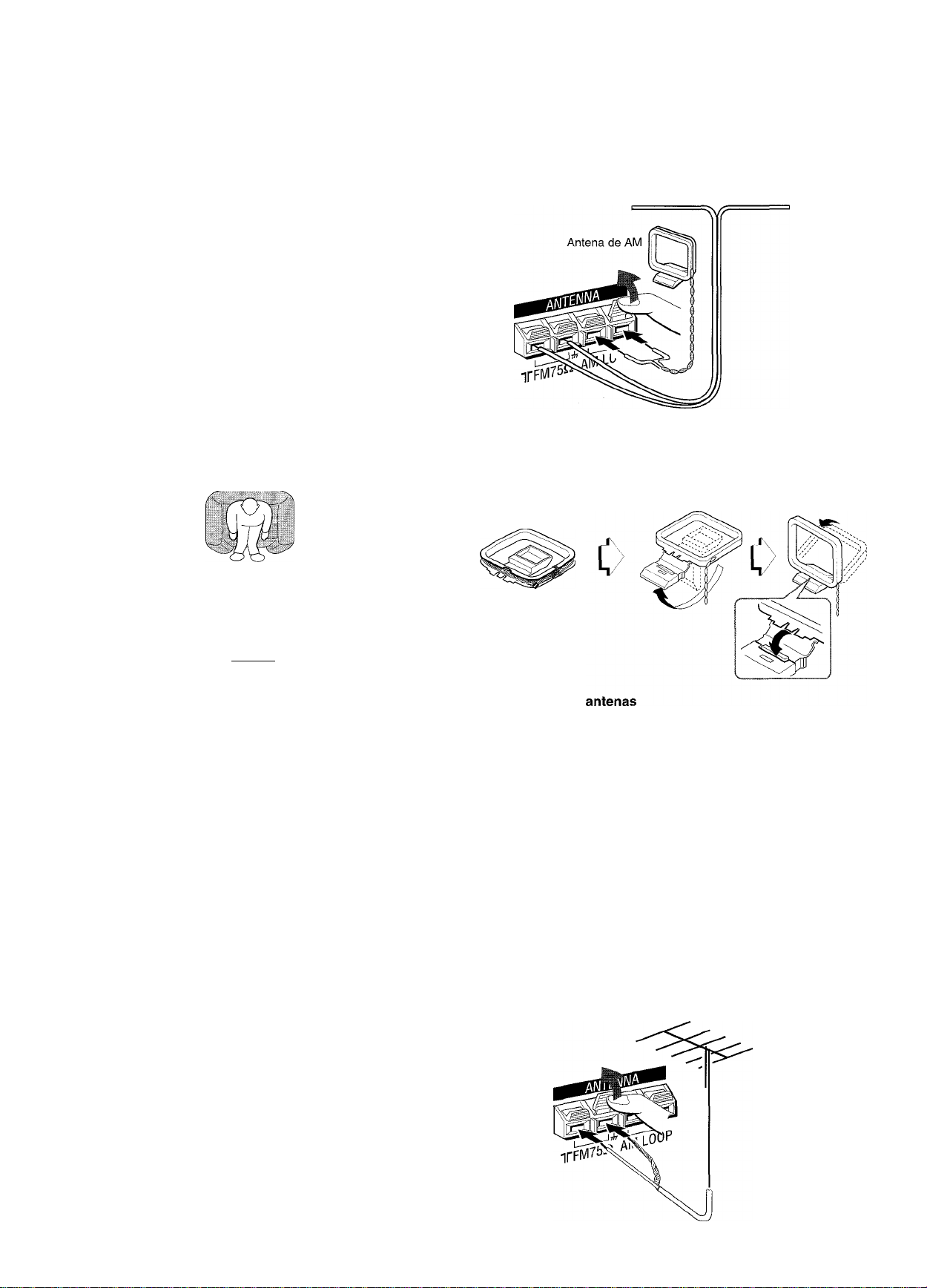
CONEXION DE LAS ANTENAS
SUMINISTRADAS (D
Conecte la antena de FM a los terminales FM 75 Í2 y la antena
de AM a los terminales AM LOOP.
(a) Altavoces delanteros
(g) Altavoz central
Colóquelo en el centro de los dos altavoces delanteros.
Además, si ha conectado un televisor a la unidad, coloque el
altavoz sobre o debajo del mismo.
© Altavoces perimétricos
Colóquelos directamente a los lados del área de escucha o
ligeramente detrás de ella. Alinéelos horizontalmente, a
aproximadamente 1 metro sobre la altura de los oídos. -
© Altavoz de subgraves
Coloque el altavoz de subgraves entre los dos aaltavoces
delanteros.
El sonido procedente de los altavoces perimétricos o del altavoz
central dependerá del ajuste del DSP, de Dolby Pro Logic, y de
la función 5,1 CH.
1
©
® ® ®
Antena de FM
Para colocar la antena de cuadro de AM sobre una
superficie
Fije la uña en la ranura como se muestra en la ilustración.
R
I c y
TV
Antena en T de FM:
Extienda horizontalmente esta antena en forma de T y fije sus
extremos a una pared.
Antena de cuadro de AM:
Colóquela con la orientación óptima.
' No acerque la antena de FM a objetos metálicos ni a rieles de
cortinas.
' No acerque la antena de AM a otros equipos externos, la propia
unidad, el cable de alimentación de CA, ni los cables de los
altavoces, porque podría captar ruido.
■ No desbobine la antena de cuadro de AM.
CONEXION DE UNA ANTENA EXTERIOR
Para mejorar la recepción de FM, se recomienda utilizar una
antena exterior. Conecte la antena exterior a los terminales FM
75 Q.
5 ESPAÑOL
Page 27
SOBRE EL CONTROLADOR REMOTO
Inserción de las pilas
Quite la tapa del compartimiento de las pilas de la parte posterior
del controlador remoto e Inserte dos pilas R6 (AA).
c
Cuándo reemplazar las pilas
La distancia máxima de operación entre el controlador remoto y
el sensor de la unidad deberá ser de aproximadamente 5 metros.
Cuando esta distancia se reduzca, reemplace las pilas por otras
nuevas.
Utilización del controlador remoto
Las instrucciones de este manual se refieren principalmente a
los botones de la unidad principal. Los botones del controlador
remoto con los mismos nombres que los de la unidad principal
también podrán utilizarse.
• Cuando no vaya a utilizar la unidad durante mucho tiempo,
extráigale las pilas para evitar la posible fuga de su electrólito.
• Es posible que el controlador remoto no funcione correctamente
cuando:
- La línea de visión entre el controlador remoto y el sensor de
control remoto del interior del visualizador esté expuesta a
una luz intensa como, por ejemplo, la luz solar directa.
- Estén utilizándose cerca otros controladores remotos (de un
televisor, etc.).
Botón FUNCTION
Cada vez que presione este botón, la fuente de sonido cambiará
cíclicamente en la forma siguiente: FM (oAM)=» V3 V2 ->
VI ->■ CD -»• AUX -> PRONO.
a): Aparecerá la banda que haya sintonizado por última vez.
Botones TUNER PRESET/SURROUND
Sintonizan las emisoras memorizadas en el receptor.
Para pasar a un número de memorización más alto, presione el
botón UP^W. Para pasar a un número de memorización máis
bajo, presione el botón DOWNM^.
Este botón se utiliza también para ajustar el equilibrio del nivel
de los altavoces del modo DSP, Dolby Pro Logic, o 5,1 CH.
No es necesario que presione el botón AIWA RECEIVEFt cada
vez que controle su receptor Aiwa a menos que haya ajustado
otro modo. (Consulte "UTILIZACION DEL CONTROLADOR
REMOTO" de la página 16.)
Si el receptor no puede gobernarse con el
controlador remoto
Realice los pasos siguientes con el controlador remoto.
1 Presione el botón AIWA RECEIVER.
2 Mantenga presionado el botón SET UP durante
unos 2,5 segundos.
El indicador de la parte superior del controlador remoto
parpadeará dos veces mientras presione el botón.
3 Presione los botones DIGIT en el orden de “4”,
“0”, y “6”.
U)
O
>
cc
2
LU
CC
Q.
Operación del controlador remoto
Este sistema de cotrol remoto le permitirá gobernar equipos
externos además del receptor Aiwa. Con respecto a los detalles
sobre la operación de control remoto de gobernar equipos
externos, consulte "CONTROLADOR REMOTO" de la página
16.
A continuación se explica cómo controlar el receptor Aiwa.
□□a
□aa
□oa
AIWA
RECEIVER ■
MUTE
POWER ■
FUNCTION ■
1 Presione el botón AIWA RECEIVER para poner
Qj o
too
» o o c
CBCZ)
■ RECEIVER
KEY
■ TUNER PRESET/
SURROUND
■ VOLUME
el controlador remoto en el modo de receptor
Aiwa.
2 Presione uno de los botones indicados arriba.
ESPAÑOL. 6
Page 28
ANTES DE LA OPERACION
PUESTA EN HORA DEL RELOJ
POWER TAPE MONITOR
PHONES FRONT SPEAKERS A, B Botones de función
VOLUME CLOCK
Para conectar la alimentación de ia unidad
Presione uno de ios botones de función (TUNER,
PHONO, AUX, CD, VIDEO 1/5.1 CH, VIDEO 2 o VIDEO
3) o el botón TAPE MONITOR.
Cuando presione el botón TUNER, se recibirá la emisora
previamente sintonizada (función de reproducción directa).
Tambión podrá utilizarse el botón POWER.
La operación será posible después de cuatro segundos, mientras
esté visualizándose el nivel de VOL (volumen) o el nombre de
la función, uno tras otro, y el indicador de la función seleccionada
esté parpadeando.
Selección dei sistema de altavoces delanteros
Cuando conecte por primera vez el cable de alimentación de
CA, la indicación del reloj parpadeará.
Ajuste la hora de la forma siguiente con la alimentación
desconectada.
1 Presione el botón SET.
La hora parpadeará.
Para utilizar el sistema de altavoces A: Ponga el botón FRONT
SPEAKERSAen *ON.
Para utilizar el sistema de altavoces B: Ponga el botón FRONT
SPEAKERS B en *ON.
Para utilizar ambos sistemas de altavoces: Ponga ambos
botones en .«.ON.
Para desconectar uno de los sistemas (o ambos sistemas) de
altavoces, ponga el botón (o los botones) en J.OFF.
Como los sistemas de altavoces delanteros A y B están
conectados en serie:
- El sonido se reducirá ligeramente cuando utilice ambos
sistemas de altavoces.
- No se oirá sonido si los botones FRONT SPEAKERS A y B
están en j».ON cuando solamente haya conectado un
sistema de altavoces.
Utilización de auricuiares
Conecte los auriculares con clavija estéreo estándar (6,3 mm
de diá.) en la toma PHONES. Cerciórese de que los botones
FRONT SPEAKERS A y B no estén en J.OFF. De lo contrario,
el sonido saldría a través de los altavoces.
Cuando enchufe los auriculares, se cancelará automáticamente
la función 5,1 CH, Dolby Pro Logic, o el sistema del DSP.
Para desconectar la alimentación de la unidad, presione
el botón POWER.
2 Presione el botón DOWNT o UPA para designar
la hora.
3 Presione el botón SET para introducir la hora.
La hora dejará de parpadear y comenzarán a hacerlo los
minutos.
4 Presione el botón DOWNT o UPA para designar
los minutos.
5 Presione el botón SET para introducir los
minutos.
Los minutos dejarán de parpadear y el reloj comenzará a
funcionar a partir de 00 segundos.
Para corregir ia hora actuai
Presione el botón POWER para desconectar la alimentación de
la unidad. Presione el botón SET y realice los pasos 1 a 5
anteriores.
Para hacer que se visualice la hora actual
Presione el botón CLOCK del controlador remoto. El reloj se
visualizará durante 4 segundos.
Para cambiar al modo de 24 horas
Presione el botón POWER manteniendo pulsado el botón UPA
o DOWNT mientras esté visualizándose la hora actual.
Para volver al modo de 12 horas, repita el mismo procedimiento.
Si ia indicación dei reloj parpadea mientras ia alimentación esté desconectada
Esto se deberá a una interrupción del suministro eléctrico. Usted
tendrá que volver a poner en hora el reloj.
Si el suministro eléctrico se interrumpe durante más de 24 horas,
todos los ajustes almacenados en la memoria después de haber
adquirido la unidad tendrán que volver a memorizarse.
7 ESPAÑOL
Page 29
AJUSTE DEL SONIDO A SU
GUSTO
T-BASS
VOLUME
SISTEMA SUPER T-BASS
El sistema T-BASS realza el realismo del sonido de baja
frecuencia.
Presione el botón T-BASS.
Cada vez que presione el botón, el nivel cambiará.
Seleccione a su gusto uno de los tres niveles o la posición de
cancelación.
IL:.«
I ll?33.i i
(/}
o
ccz
Sj««
cc
o.
BBE
MUTING BALANCE
CONTROL DEL VOLUMEN
Gire el control VOLUME de la unidad o presione los botones
VOLUME del controlador remoto.
El nivel del volumen se mostrará en el visualizador durante cuatro
segundos. Este nivel podrá ajustarse entre 0 y MAX (31). La
indicación parpadeará cuando el nivel se haya ajustado a más
de 21.
El nivel del volumen permanecerá memorizado incluso después
de haber desconectado la alimentación. Sin embargo, si
desconecta la alimentación cuando el nivel del volumen esté
ajustado a más de 17, la próxima vez que vuelva a conectarla
se ajustará automáticamente a 16.
Para ajustar el equilibrio entre los altavoces delanteros
izquierdo/derecho
Presione el botón BALANCE para hacer que se visualice “L/R
OdB”. Después presione repetidamente el botón DOWNT o
UPA antes de cuatro segundos. Tenga en cuenta que también
cambiará el equilibrio de los altavoces delanteros de ios modos
5,1 CH y Dolby Pro Logic.
Para silenciar temporaimente el sonido
Presione el botón MUTING (-20 dB).
En el visualizador aparecerá “MUTE ON” durante cuatro
segundos. Mientras el sonido esté silenciado, el indicador de
función seleccionado parpadeará. Para restablecer el sonido,
vuelva a presionar el botón MUTING.
IB:rj.t.1 —»■ iMüüi -
El sonido de baja frecuencia puede distorsionarse cuando utilice
el sistema T-BASS con un disco o un casete cuyo sonido de
baja frecuencia haya sido acentuado originalmente. En este
caso, cancele el sistema T-BASS.
(cancelación)
AJUSTE DEL SONIDO DURANTE LA GRABACION
El volumen y el tono de salida de los altavoces o de los
auriculares podrán vanarse libremente sin que se vea afectado
el nivel de grabación.
SISTEMA BBE
El sistema BBE realza la claridad del sonido de alta frecuencia.
Presione el botón BBE.
Cada vez que presione el botón, el nivel cambiará. Seleccione
a su gusto uno de ios tres niveles o la posición de cancelación.
ÉtIiU—» laaa—► igga -
1^1
• El sistema BBE se cancelará automáticamente:
- cuando active el modo Dolby Pro Logic
- cuando seleccione la función 5,1 CH
• El sistema BBE no podrá activarse cuando haya seleccionado
la función 5,1 CH.
I (cancelación)
ESPAÑOL 8
Page 30
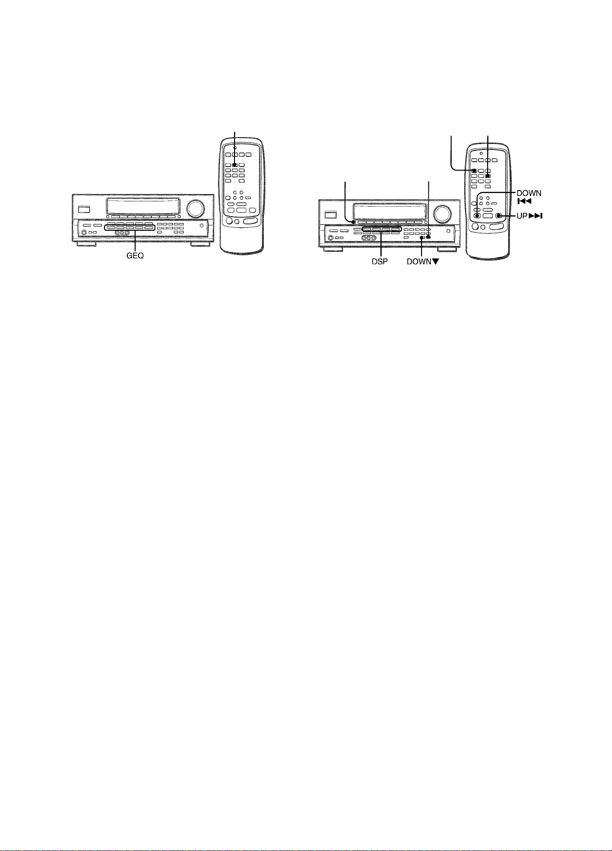
ECUALIZADOR GRAFICO
SONIDO PERIMETRICO DEL
ELECTRONICO
GEQ
Esta unidad dispone de ios cinco modos de ecuaiización
siguientes.
ROCK: Acentúa ei sonido de graves y agudos.
POP: Ofrece más presencia a las voces y a la gama media.
JAZZ: Acentúa las frecuencias bajas para música de tipo jazz.
CLASSIC: Ofrece sonido rico con graves profundos y agudos
delicados.
BGM: Ofrece tono calmado con graves y agudos suprimidos.
Presione uno de los botones GEQ (ecualizador gráfico).
El nombre del modo seleccionado aparecerá en el visualizador
durante cuatro segundos, y en se encerrará entre paréntesis en
el visualizador.
PROCESADOR DE SEÑAL DIGITAL
MANUAL
DSP
SELECT
MANUAL
SELECT
Los circuitos de sonido perimètrico del procesador de señal
digital (DSP) pueden recrear el efecto de sonidos reflejados en
paredes o techos, para ofrecer la presencia de sonido de
ambientes reales. Existen cuatro modos correspondientes a los
modos de ecuaiización gráfica. Los modos de ecuaiización se
seleccionarán automáticamente, y también podrá seleccionar o
desactivarlos a su gusto.
Presione uno de los botones DSP (procesador de señal digital) (DANCE, UVE, HALL o ARENA).
El nombre del modo seleccionado aparecerá en el visualizador
durante cuatro segundos, y también se visualizarán los modos
del DSP y del GEQ adecuados.
UPA
Mdo del DSP seleccionado
.
---------
1
Modo seleccionado
Para cancelar el modo seleccionado
Vuelva a presionar el botón seleccionado. En el visualizador
aparecerá “GEQ OFF”.
Para seleccionar con el controlador remoto
Presione repetidamente el botón GEQ hasta que se visualice el
modo de ecuaiización deseado.
Modo de GEQ correspondiente
Cuando la fuente de música sea monoaural
Seleccione LIVE para obtener un efecto estéreo simulado. Si
selecciona DANCE, HALL o ARENA no oirá sonido a través de
los altavoces perimétricos.
Para cancelar el modo seleccionado
Vuelva a presionar el botón seleccionado. En el visualizador
aparecerá “DSP QFF”. Incluso aunque haya cancelado el modo
del DSP seleccionado, ei modo del GEQ adecuado o
seleccionado permanecerá en el visualizador.
Para seleccionar con el controlador remoto
Presione repetidamente el botón DSP hasta que se visualice el
modo de ecuaiización deseado.
Para ajustar el volumen y el equilibrio de los altavoces
perimétricos
Presione dos o tres veces el botón MANUAL SELECT, mientras
el sistema del DSP esté activado, para hacer que se visualice
“S-R OdB” (para el altavoz perimètrico derecho) o “S-L OdB” (para
el altavoz perimètrico izquierdo). Después presione
repetidamente el botón DQWNT o UPA antes de cuatro
segundos.
Tenga en cuenta que también podrá cambiar el volumen y el
equilibrio de los altavoces de los modos 5,1 CH y Dolby Pro
•
Logic.
• El sistema del DSP se cancelará automáticamente:
- cuando active el modo Dolby Pro Logic
- Cuando seleccione la función 5,1 CH
• El sistema del DSP no podrá activarse:
- cuando haya seleccionado la función 5,1 CH.
- cuando haya enchufado unos auriculares
9 ESPAÑOL
Page 31
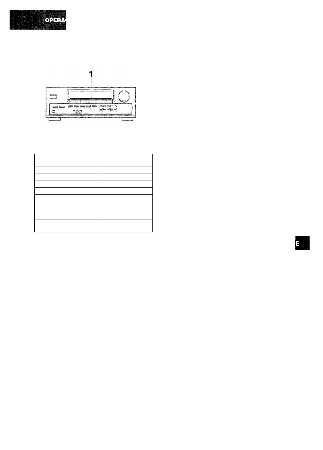
â
SELECCION DE UNA FUENTE DE
AUDIO/VIDEO
1 Seleccione la fuente de programas.
Presione uno de los botones de función o el botón TAPE
MONITOR.
Para escuchar o contemplar
Cintas
La radio TUNER
Discos analógicos
Televisión, etc.
Discos compactos
Videocintas VIDEO 1/5.1 OH,
Discos láser o programas de
cablevisión
Minidiscos 0 videodiscos
digitales
Los botones de función a presionarse (excepto PHONO)
parpadearán del equipo conectado a los terminales de
entrada del panel posterior de la unidad.
Botón presionado
TAPE MONITOR
PHONO
AUX
CD
VIDEO 2, VIDEOS
VIDEO 2
VIDEO 1/5.1 OH
Para cambiar el nombre visualizado para el botón VIDEO
1/5.1 CHyel botón VIDEO 2
Cuando presione ei botón VIDE01/5.1 OH, inicialmente se
visualizará VIDEO 1. Usted podrá cambiar la indicación a DVD
o MD.
Para conectar ia alimentación, presione el botón POWER
manteniendo pulsado el botón VIDE01/5.1 OH.
Este botón VIDEO 1/5.1 OH también trabajará comio selector de
función 5,1 OH (5.1 INPUT). Mientras esté visualizándose el
nombre de la función seleccionada (VIDEO 1, DVD, o MD) para
el botón VIDEO 5.1 OH, vuelva a presionar este botón. El nombre
de la función cambiará a “5.1 OH”, y se seleccionará la fuente
conectada a los terminales 5.1 INPUT.
Para reanudar, vuelva a presionar el botón de forma que se
visualice el nombre de la función seleccionada.
El nombre visualizado para el botón VIDEO 2 podrá cambiarse
a VIDEO 2, LD, o TV. Con la alimentación conectada, presione
el botón POWER manteniendo pulsado el botón VIDEO 2.
Para ajustar el nivel del sonido de la fuente conectadei
El nivel de sensibilidad de entrada de cada función (excepto las
funciones TUNER y 5,1 OH) podrá ajustarse.
Cuando el nivel del sonido de la fuente conectada sea superior
0 inferior al de TUNER, ajúsfelo de la forma siguiente.
1 Seleccione la función que desee ajustar.
Presione el botón de función correspondiente y ponga la
fuente en reproducción.
2 Presione repetidamente el botón UP A o DOWN
■Ï-.4
líi№
El nivel podrá ajustarse entre -6 dB (MIN) y +8 dB (M.AX) en
pasos de 2 dB. Ajuste el nivel de forma que el sonido salga con
el mismo nivel que el de TUNER.
§S
O o
Q.
(/}
<
O
U)
<
<
tr
UJ
O
Cuando utilice un giradiscos con amplificador incorporado,
desconecte la alimentación del amplificador ecualizador. Para
más información, consulte el manual de instrucciones del
giradiscos.
2 Poinga en reproducción ia fuente de programas
seleccionada.
3 Ajuste el sonido.
Sobre la fuente de vídeo para el monitor o el televisor
Fuente de vídeo seleccionada
VI: VIDEO 1, V2: VIDEO 2, V3: VIDEO 3
La fuente de vídeo seleccionada se indicará en el visualizador,
y la señal de vídeo aplicada a la toma MONITOR VIDEO OUT
saldrá al televisor.
I
' El nivel de sensibilidad de entrada de la función TUNER o 5,1
OH no podrá ajustarse.
' Tampoco podrá ajustarse el de TAPE MONITOFT
Aunque haya seleccionado TAPE MONITOR y el indicador
TAPE MONITOR se haya vuelto rojo, al presionar el botón UPA
o DOWNT, el nivel de la función indicada en el visualizador
cambiará.
ESPAÑOL 10
Page 32

PARA REPRODUCIR UN VIDEODISCO
DIGITAL GRABADO CON SONIDO DOLBY
DIGITAL SURROUND
Este receptor posee conectores 5.1 INPUT que permiten la
conexión de un decodificador Dolby Digital con terminales de
salida de 5,1 canales. Cuando conecte al receptor un reproductor
de discos DVD que contiene un decodificador Dolby Digital,
podrá disfrutar de sonido con la calidad de un cine en su hogar
cuando reproduzca discos grabados con sonido Dolby Digital
Surround.
1 Presione el botón VIDEO 1/5.1 CH para
seleccionar la función VIDEO 1 (DVD o MD).
2 Vuelva a presionar el botón VIDEO 1/5.1 CH.
En el visualizador aparecerá “5.1 CH”, y como fuente se
seleccionará el reproductor de discos DVD conectado a ios
terminales 5.1 INPUT.
GRABACION DE UNA FUENTE DE
AUDIO
1 Seleccione la fuente de programas que desee
grabar.
Presione uno de los botones de función.
2 Ponga el deck de casetes o el grabador de
minidiscos en el modo de grabación.
3 Ponga en reproducción la fuente de programas
seleccionada.
3 Inicie la reproducción del disco DVD grabado con
sonido Dolby Digital.
Para reanudar la función de VIDEO 1, DVD (2 canales estéreo),
o MD, vuelva a presionar el botón VIDEO 1/5.TCH.
' La función 5,1 CH se cancelará y se selecionará la función
VIDE01, DVDoMD:
- cuando active el modo Dolby Pro Logic
- cuando enchufe unos auriculares
’La función 5,1 CH no podrá seleccionarse cuando haya
enchufado unos auriculares.
Para escuchar el sonido grabado durante la grabación
(cuando el deck de casetes conectado posee un sistema
de tres cabezas)
Presione el botón TAPE MONITOR. En el visualizador aparecerá
“TAPE ON” durante cuatro segundos, y después volverá a
aparecer el nombre de la fuente seleccionada en el paso 1. Para
cancelar la escucha, vuelva a presionar el botón para que
aparezca “TAPE OFF”.
' Ningún sistema de control del sonido tendrá efecto en la
grabación (consulte la página 8).
' El sonido de entrada a través de los terminales 5.1 INPUT no
podrá grabarse. Para grabar el sonido procedente de un
reproductor de discos DVD, conecte los terminales AUDIO OUT
(DOWN MIXING) de dicho reproductor a los terminales VIDEO
1/DVD/MD AUDIO IN de la unidad.
’ Para grabar fuentes mediante el grabador de minidiscos
conectado a los terminales VIDEO 1/DVD/MD AUDIO OUT,
seleccione la fuente después de haber presionado el botón
VIDEO 2 o VIDEO 3 (deberá visualizarse V2 o V3).
La grabación no podrá realizarse mientras esté visualizándose
la indicación VI.
’ El sonido procedente de la grabadora de casetes conectada a
los terminales TAPE MONITOR IN no podrá grabarse.
11
ESPAÑOL
Page 33
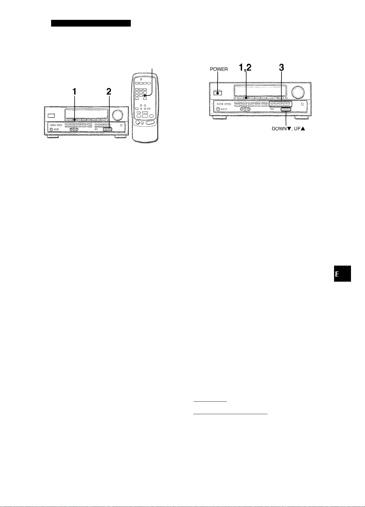
ESCUCHA DE LA RADIO
SINTONIA MANUAL SINTONIA DIRECTA
MONO
TUNER
Cuando conozca ia frecuencia de la emisora deseada, podrá
1 Presione repetidamente el botón TUNER para
seleccionar la banda deseada.
-►AM
FM
r
La visualización cambiará a la indicación de la frecuencia
después de haber mostrado la banda y la fuente de vídeo
(VI, V2, o V3) durante dos segundos.
Cuando presione el botón TUNER con la alimentación
desconectada, la alimentación se conectará directamente.
□
sintonizarla directamente.
1 Presione el botón TUNER para seleccionar una
banda.
2 Mantenga presionado ei botónTUNEFt hasta que
en el visualizador parpadee “...........” (modo de
sintonía directa).
m <
íSm
z Q
o<
cc ^
Q. (I)
Qin
Presione el botón UPA o DOWNT para
seleccionar una emisora.
Cada vez que presione el botón, la frecuencia cambiará.
Cuando se reciba una emisora, se visualizará “TUNE” durante
dos segundos. Durante la recepción de FM estéreo, se
visualizará l(i®il).
Para buscar rápidamente una emisora (búsqueda
automática)
Mantenga presionado ei botón UPA o DOWNT hasta que ei
sintonizador comience a buscar una emisora. Después de
haberse sintonizado una emisora, la búsqueda se parará.
Para parar manualmente la búsqueda automática, presione el
botón UPA o DOWNT.
• La búsqueda automática es posible que no se pare en emisoras
de señal muy débil.
Cuando un programa de radiodifusión de FM estéreo
contenga ruido
Presione el botón MONO TUNER del controlador remoto para
que en el visualizador aparezca “MONO”.
El ruido se reducirá, pero la recepción será monoaural.
MONO
Para restablecer la recepción estéreo, presione el botón para
que desaparezca “MONO”.
3 Presione los botones numéricos apropiados para
sintonizar ia emisora deseada.
Ejemplo;
Para sintonizar 106,50 MHz, presione los botones 1,0, 6, 5,
y 0.
Para sintonizar 95,20 MHz, presione los botones 9, 5, 2, y 0.
Para cancelar el modo de sintonía directa
Presione el botón UPA o DOWNT.
’ Si introduce una frecuencia fuera de la gama de sintonía, ésta
parpadeará durante dos segundos y después desaparecerá.
Compruebe la frecuencia y repita correctamente el paso 3.
’ Si introduce una frecuencia no cubierta por el intervalo de
sintonía, ésta se redondeará automáticamente por defecto o
exceso a la más cercana cubierta por el intervalo de sintonía.
' Los botones DIGIT del controlador remoto no podrán utilizarse
para sintonizar emisoras.
Para cambiar el intervalo de sintonía de AM
El ajuste inicial del intervalo de sintonía de AM es de 10 kH2:/
paso. Para utilizar esta unidad donde el sistema de
asignación de frecuencias sea de 9 kHz/paso, cambie el
intervalo de sintonía.
Mantenga presionado el botón TUNER y presione
inmediatamente el botón POWER. Tenga en cuenta que si
mantiene presionado el botón TUNER durante
aproximadamente medio segundo, la unidad entrará en el
modo de sintonía directa.
Para volver al intervalo anterior, repita este procedimiento.
ESPAÑOL
12
Page 34

MEMORIZACION DE EMISORAS
2 1
La unidad podrá almacenar un total de 32 emisoras. Cuando
aimacene una emisora, se ie asignará un número de
memorización. Utilice el número de memorización para sintonizar
directamente ia emisora aimacenada.
1 Presione el botón TUNER para seleccionar la
banda, y presione el botón UPA o DOWNT para
seleccionar la emisora. Usted también podrá
utilizar la sintonía directa.
SINTONIA DE EMISORAS POR SU NUMERO DE MEMORIZACION
1 Presione el botón TUNER para seleccionar una
banda.
2 Presione los botones numéricos para introducir
el número de memorización.
Ejemplo:
Para introducir el número de memorización 25, presione 2 y
5.
Para introducir ei número de memorización 7, presione 0 y 7.
Para borrar una emisora memorizada
introduzca el número de memorización de la emisora que desee
borrar. Después presione ei botón SET, y antes de cuatro
segundos vueiva a presionar el botón SET.
Los números de memorización de todas las demás emisoras de
la banda de número superior se reducirán una unidad.
Cuando utilice el controlador remoto
Presione los botones UP^W o DOWN
un número de memorización.
Los botones DIGIT del controlador remoto no podrán utilizarse
para seieccionar un número de memorización.
para seleccionar
2 Presione el botón SET para almacenar le emisora.
En ei visuaiizador parpadeará durante dos segundos un
número de memorización asignado a ia emisora, en orden
consecutivo, comenzando por 1, para cada banda.
.i.
. . -
3 Repita los pasos 1 y 2.
La emisora siguiente no se almacenará si ya ha almacenado
un total de 32 emisoras para todas las bandas.
Cuando cambie el intervalo de sintonía de AM, se borrarán todas
las emisoras memorizadas. En este caso tendrá que volver a
memorizar las emisoras.
13 ESPAÑOL
Page 35
I
Esta unidad dispone de un decodificador Dolby Pro Logic y
también permite la conexión de un decodificador Dolby Digital
con terminales de salida de 5,1 canales.
Los altavoces central y perimétricos (estándar) aseguran sonido
de cine a plena escala para el hogar. Cuando reproduzca discos
o software de vídeo grabados con Dolby Pro Logic o Dolby Digital
Surround, un sonido sorprendentemente realista rodeará al
oyente para crear un nuevo nivel de entretenimiento audiovisual.
El control independiente de los cinco canales permitirá al oyente
disfrutar del mismo tipo de reproducoión de sonido que el
experimentado en salas de cine. Las voces se reproducirán en
el campo acústico delantero y central, mientras que los sonidos
ambientales como el de automóviles o multitudes se reproducirá
por todos los lados del oyente y le ofrecen una experiencia
audiovisual increíblemente realista. Lea cuidadosamente lo
siguiente para “sintonizar” la salida del sistema de acuerdo con
ias características de su espacio de escucha.
Compruebe lo siguiente:
• Antes de disfrutar de sonido DOLBY SURROUND, ajuste
el equilibrio apropiado de los niveles de sonido de los
altavoces (consulte la página 15).
• Cerciórese de que ios altavoces estén adecuadamente
conectados y ubicados (consulte las páginas 3, 4, y 5).
• Cerciórese de que el televisor y la unidad de vídeo estén
adecuadamente conectados (consulte la página 3).
•Cerciórese de que el disco, la videocinata, etc., sean del
sistema Dolby Pro Logic o Dolby Digital Surround.
PARA SELECCIONAR UN MODO DOLBY PRO LOGIC
1,2
^
i B
.................
i b
1 @ oo
Presione repetidamente el botón DOLEÌY SURROUND para seleccionare! modo apropiado.
Cuando seleccione el modo DOLBY PRO LOGIC o 3
STEREO, se encenderá el indicador, y en el visualizador se
desplazará el nombre del modo seleccionado. Cada vez que
presione el botón, el modo cambiará como se indica a
continuación.
DOLBY PRO LOGIC
......
1
Z3 CZ3 crrp cm CX3 CDCZtaCZtCD ^ 1
CDCDC3CDC3 n i1=3 t=IC3 J j
------
► 3 STEREO
zO
-------
1
g
Q o
<z
CC =)
<C)
CC
oc
LU
3 :
Q
(ñ
<
>■
X
ai
o
3
o
u
Q
(/¡
LU
SELECCION DE DOLBY PRO
LOiíülC
El modo Dolby Pro Logic óptimo dependerá del tipo y la ubicación
de los altavoces. Se recomienda utilizar altavoces Aiwa
opcionales para todos los canales, por ejemplo, SX-R2500 para
los altavoces perimétricos, SX-C2500 para el altavoz central, y
SX-AV2500 para los altavoces delanteros. Compruebe el tipo y
la ubicación de sus altavoces y seleccione el modo Dolby Pro
Logic recomendado correspondiente.
Modo recomendado
Altavoz central
Más grande
Altavoces perimétricos
(altavoces traseros)
Sin altavoces
perimétricos
Modo PHANTOM: Seleccione este modo cuando no haya
conectado un altavoz central. Todas las señales del canal central
se redistribuirán a los altavoces de los canales izquierdo y
derecho.
Modo 3 STEREO: Seleccione este modo cuando no haya
conectado altavoces perimétricos.
DOLBY PRO
LOGIC-WIDE
3 STEREO
WIDE
Más pequeño
DOLBY PRO
LOGIC-NORMAL
3 STEREO
NORMAL
Sin altavoz
PHANTOM
-
DOLBY PRO LOGIC OFF(cancelación )
ón) <—I
2 Mantenga presionado el botón DOLE3Y
SURROUND hasta que aparezca el modo de
altavoz central deseado.
Cuando haya seleccionado el modo DOLBY PRO LOGIC en el paso 1:
Aparecerán “NORMAL”, “WIDE”, y “PHANTOM", uno tras otro.
Cuando haya seleccionado 3 STEREO en el paso 1:
Aparecerán “NORMAL” y “WIDE”, uno tras otro.
• Dependiendo de la fuente de sonido o de las condiciones de
escucha, es posible que no obtenga efecto perimètrico incluso
aunque haya activado el sistema Dolby Pro Logic.
• El efecto pleno de Dolby Pro Logic no podrá obtenerse cuando
se utilice software sin la marca □□|q°i.°vsubb°u™| . En este caso,
utilice en su lugar el sistema perimètrico del DSP (consulte la
página 9).
• El sistema Dolby Pro Logic se cancelará automáticamente:
- cuando active el sistema BBE o DSP
- cuando seleccione la función 5,1 CH
- cuando enchufe unos auriculares
• Dolby Pro Logic no podrá activarse cuando haya enchufado
unos auriculares.
ESPAÑOL 14
Page 36

AJUSTE DEL EQUILIBRIO DEL
NIVEL ENTRE ALTAVOCES
Ajuste el nivel del sonido de los altavoces dentral
y perimétricos.
Mientras esté parpadeando “CEN”, “S-L”, o “S-R” en el
visualizador, presione el botón UPA o DOWNT de forma
que el nivel del sonido de los altavoces central o perimétricos
coincida con ei de los altavoces delanteros.
<GE, LIVE HALL ARENA
:x/ ■ o .A.»-' ■ r-‘.v
■
' / I \
El equilibrio de los altavoces delanteros también podrá
ajustarse mientras esté visualizándose “L/R”.
4 Para parar la señal de ruido, vuelva a presionar
el botón MANUAL SELECT.
Esta unidad dispone de un generador de señal de prueba
incorporado denominado secuenciador de ruido para facilitar el
ajuste del equilibrio de los cinco canales.
El secuenciador da salida a una señal de ruido que “viaja” de
canal a canal para permitir el ajuste sencillo del nivel del sonido
a fin de obtener la misma sonoridad aparente desde cada canal
en su posición de escucha.
1 Seleccione el modo Dolby Pro Logic de acuerdo
con el tipo y la ubicación de sus altavoces.
(Consuite ia página 14.)
2 Mantenga presionado el botón MANUAL SELECT
durante unos dos segundos hasta que aparezca
“L/R OdB”.
fpQLBYPBüLDGÍC^
/|\
A cada canal se enviará ana señal de ruido de la forma
siguiente:
Modo DOLBY PRO LOGIC NORMAL o WIDE
L/R OdB (Altavoz delantero izquierdo)*’
I
CEN OdB (Altavoz central )
I
L/R OdB (Altavoz delantero derecho)*’
• El botón UP^W o DOWNM^ del controlador remoto no podrá
utilizarse en ei paso 3 cuando se ajuste el equilibrio entre los
altavoces con señales de ruido.
• Cuando ajuste el equilibrio del nivel de los altavoces Cuando
ajuste el equilibrio del nivel de los altavoces en el modo Dolby
Pro Logic, también cambiará el de los modos del DSP y 5,1
CH.
Información sobre los canales
Los altavoces izquierdo y derecho crean el efecto estéreo.
El altavoz central ayuda a ubicar con precisión el sonido en un
campo acústico amplio.
Los altavoces perimétricos montados atrás realzan la
“profundidad” del campo acústico.
Para cambiar ei tiempo de retardo de ios aitavoces perimétricos en el modo Dolby Pro Logic
Los altavoces perimétricos reproducen sonidos una fracción de
segundo después de los altavoces delanteros. Este retardo está
ajustado inicialmente a 20 ms (milisegundos).
Para cambiar el tiempo de retardo estándar, presione
repetidamente ei botón MANUAL SELECT hasta que se visualice
“SUR”. Después presione el botón UPA o DOWNT. Cada vez
que presione uno de los botones, el tiempo de retardo cambiará
como se indica a continuación.
r>15ms-< '•20ms-
►30ms
S-R OdB (Altavoz perimètrico derecho)*^
S-L OdB (Altavoz perimètrico izquierdo)*^
I
________________________
Modo DOLBY PRO LOGIC PHANTOM
I—► L/R OdB*'—► L/R OdB*’
I
-----
S-L 0dB*2-<
Modo 3 STEREO NORMAL o WIDE
I—► L/R OdB*'—►CEN OdB —► L/R OdB
-----
S-R OdB
'.Z]
□
*' “L” o “R” parpadeará para indicar uno de los altavoces delanteros
a través del que sale señal de ruido.
*® La señal de ruido sale a través de los altavoces perimétricos
izquierdo (L) y derecho (R) al mismo tiempo.
15 ESPAÑOL
Para ajustar ei equiiibrio del nivel de los altavoces
mientras escuche una fuente (modos Doiby Pro Logic y
5,1 CH)
El equilibrio del nivel de los altavoces podrá cambiarse después
de haberio ajustado con ei secuenciador de ruido. Ei equiiibrio
podrá cambiarse cuando active el sistema Dolby Pro Logic o
cuando seleccione la función 5,1 CH.
1 Ponga en reproducción un disco o software de vídeo grabado
con Dolby Pro Logic o Dolby Digital Surround.
2 Presione repetidamente el botón MANUAL SELECT hasta
que en el visualizador aparezca “L/R”, “CEN”, “S-L”, o “S-R”.
3 Presione ei botón UPA o DCWNT mientras esté
visualizándose el nombre del altavoz que desee ajustar.
En este caso también podrá utilizar el botón UP^W o
DCWNM^ del controlador remoto.
Page 37
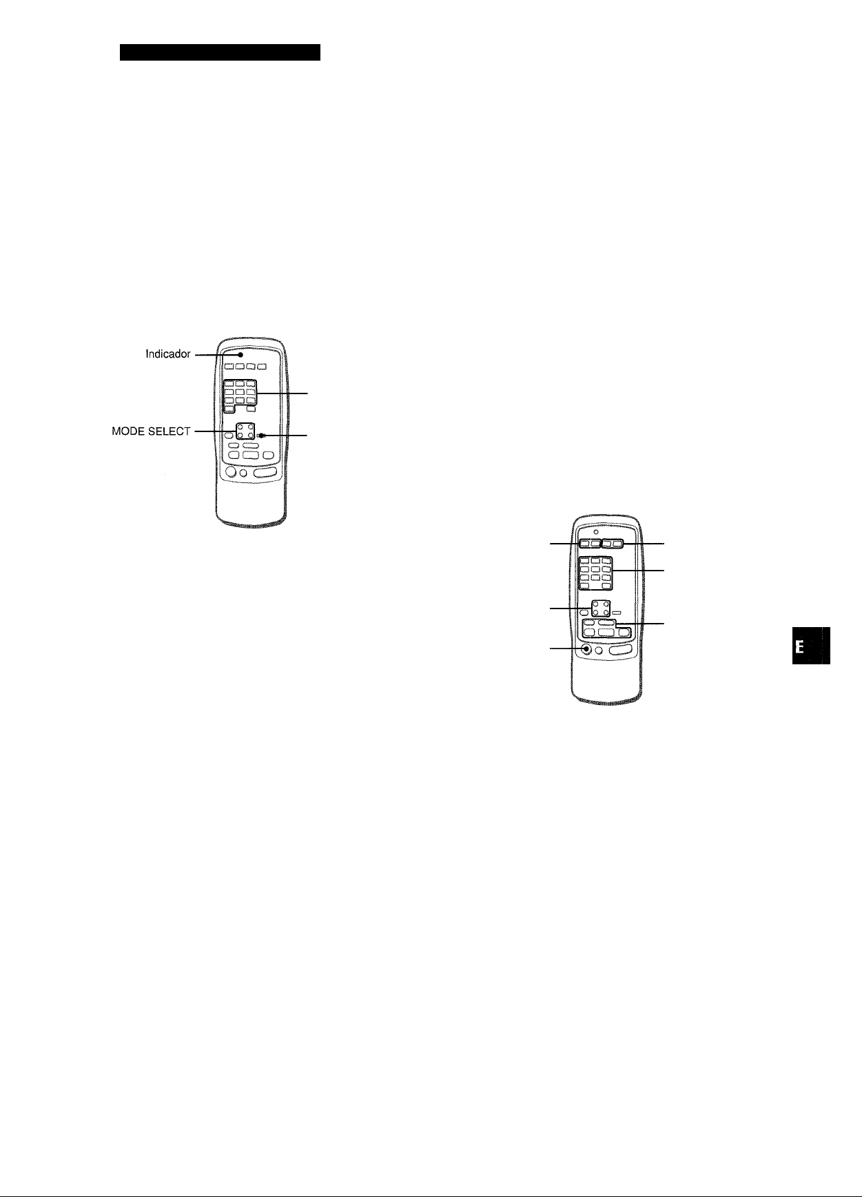
CONTROLADOR REMOTO
OPERACION OE UN TELEVISOR, SISTEMA DE
CABI.EVISION, VIDEOGRABADORA, Y
REPRODUCTOR DE DISCOS COMPACTOS
Con este controlador remoto, podrá gobernar un televisor, un
sistema de cablevisión, una videocámara, y un reproductor de
discos compactos.
PARA INTRODUCIR UN CODIGO DE IDENTIFICACION DE UN EQUIPO EXTERNO
. Botones DIGIT
(0~9)
■ SET UP
Para confirmar el código de identificación aimacenado
Usted podrá comprobar el código de identificación almacenado
contando el número que parpadea el Indicador.
1 Presione ei botón TV, CABLE, VCR, o CD.
Por ejemplo, para comprobar el código almacenado para un
reproductor de discos compactos, presione CD.
2 Mantenga presionado el botón SET UP durante unos 2,5
segundos.
3 Presione “9”, “9”, y “0”. 4 Presione “1 ”, y cuente los parpadeos del indicador.
Por ejemplo, en caso de que el código de identificación
almacenado sea “157".
El indicador parpadeará una vez.
5 Presione “2”, y cuente ios parpadeos dei indicador.
El indicador parpadeará cinco veces.
6 Presione “3”, y cuente los parpadeos del indicador.
El indicador parpadeará siete veces.
PARA CONTROLAR UN TELEVISOR, SISTEMA DE CABLEVISION, VIDEOGRABADORA, Y REPRODUCTOR DE DISCOS COMPACTOS
»“
□ o
ZS
=>UJ
ooc
“o
>- _í
CQC
OH
Q Z
O
O
ü
Antes de intentar controlar estos equipos, cerciórese de asignar
el código de identificación de los mismos al controlador remoto
de la misma de la forma siguiente.
1 Confirme el número de código del equipo
externo.
Consulte la lista de códigos de identificación del “APENDICE”
de este manual.
2 Presione el botón TV, CABLE, VCR, o CD del área
MODE SELECT.
3 Mantenga presionado el botón SET UP durante
unos 2,5 segundos.
Compruebe si el indicador parpadea dos veces manteniendo
presionado el botón SET UP.
4 Presione los botones DIGIT correspondientes
al código de identificación del equipo externo.
Por ejemplo, si su reproductor de discos compactos es AIWA,
el código de identificación requerido es 124 o 157. En este
caso, presione los botones DIGIT en el orden de “1”, “2”, y
“4” (o “1”, “5”, y “7”).
Después de haber presionado el tercer botón DIGIT, el
indicador parpadeará dos veces para indicar que el código
de identificación es correcto y que se ha almacenado en el
controlador remoto.
•
CHANNEL
MODE SELECT
POWEFÌ
VOLUME
Botones DIGIT
(0~9) y ENTER
VCR/CD
ll:Pausa,B: Parada,
Rebobinado,
►: Reproducción,
►M: Avance rápido
1 Presione cualquier botón del área MODE SELECT
(TV, CABLE, VCR, o CD).
El controlador remoto habrá quedado listo para gobernar el
equipo del modo seleccionado.
2 Presione uno de los botones indicados arriba.
Con respecto a la utilización de los botones 0 - 9 y ENTER,
consulte el manual de instrucciones suministrado con la unidad
que desee controlar.
Los demás botones indicados arriba poseen la misma función
que la de los botones de la unidad que desea controlar.
• Después de haber cambiado las pilas del controlador remoto,
vuelva a introducir el código de indentificación del equipo
externo.
• Si hay muchos códigos de identificación para un equipo externo
en la lista de “APENDICE”, pruebe a introducir uno tras otro
hasta encontrar el que permita controlar tal equipo.
ESPAÑOL
16
Page 38
■■■■ V ‘ ri
GENERALIDADES
PROGRAMACION DEL TEMPORIZADOR CRONODESCONECTADOR
oaaa
DEDO
gao
UPA, DOWNT
~
0 o
CD CID
acDO
lpo*c5j
...
................—-
O
-
c=3c=pc=3c=5c=i C3ac3c¡
Usted podrá hacer que la alimentación de la unidad se
desconecte automáticamente después del tiempo especificado.
O fa
h °
1 Presione el botón AIWA RECEIVER. 2 Presione el botón SLEEP.
2
CUIDADOS Y MANTENIMIENTO
El mantenimiento y el cuidado ocasionales de la unidad serán
necesarios para sacar el máximo partido de ella.
Para limpiar el exterior
Utilice un paño suave y seco.
Si la superficie está extremadamente sucia, utilice un paño
ligeramente humedecido en una solución poco concentrada de
detergente. No utilice disolventes fuertes, como alcohol, bencina,
o diluidor de pintura ya que podría dañar el acabado de la unidad.
1
La alimentación de la unidad se desconectará después de
unos 60 minutos.
Para especificar el tiempo hasta que se desconecte la
alimentación
Presione repetidamente el botón UPA or DOWNV de la unidad
principal antes de cuatro segundos de haber realizado el paso
2.
Cada vez que presione el botón, el tiempo cambiará entre 5 y
240 minutos en pasos de 5 minutos.
I
Tiempo especificado
Para comprobar el tiempo restante hasta que se desconecte la alimentación
Presione una vez el botón SLEEP. El tiempo restante se
visualizará durante cuatro segundos.
Para cancelar el temporizador cronodesconectador
Presione dos veces el botón SLEEP para que “SLEEP”
desaparezca del visualizador.
El botón UP^W o DOWNK4 del controlador remoto no podrá
utilizarse para especificar el tiempo hasta que se desconecte la
alimentación. Utilice los botones de la unidad principal.
17
ESPAÑOL
Page 39

ESPECIFICACIONES
Sección del sintonizador de FM
Gama de sintonía 87,5 a 108 MHz
Sensibilidad útil 13,2 dBf
Terminales de antena 75 ohmios (desequilibrados)
Sección del sintonizador de AM
Gama de sintonía 530 a 1710 kHz (intervalo de 10 kHz),
531 a 1602 kHz (intervalo de 9 kHz)
Sensibilidad útil 350 qV/m
Antena Antena de cuadro
Silenciamiento
SURROUND SPEAKERS IMP; 8ÍÍ
(altavoces peri métricos): acepta
altavoces de 8 ohmios o más
CENTER SPEAKER IMP: 80/40
seleccionable
Con el selector SPEAKER
IMPEDANCE SELECTOR en 40,
aceptará altavoces de 4 ohmios.
Con el selector SPEAKER
IMPEDANCE SELECTOR en 80,
aceptará altavoces de 8 ohmios o
más.
PHONES (toma estéreo): Acepta
altavoces de 32 ohmios o más
-20 dB
^IL
|S
o. Mj
Sz
LiJ u.
Sección del amplificador
Salida de potencia [Modo estéreo]
Altavoces delanteros
130 vatios por canal como mín., valor
eficaz, a 8 ohmios, de 40 Hz a 20
kHz, con no más del 0,9% de
distorsión armónica total
[Modo Dolby Pro Logic o 5,1 CH]
Altavoces delanteros
120 vatios por canal como mín., valor
eficaz, a 8 ohmios, de 40 Hz a 20
kHz, con no más del 0,9% de
distorsión armónica total
Altavoces traseros (peri métricos)
60 vatios por canal como mín., valor
eficaz, a 8 ohmios, 1 kHz, con no más
del 0,9% de distorsión armónica total
Altavoz central
120 vatios como mín., valor eficaz, a
8 ohmios, 1 kHz, con no más del
0,9% de distorsión armónica total
Distorsión armónica
total
Entradas
Salidas
0,08 % (85 W, 1 kHz, 8ohmios,
Altavoces delanteros)
AUDIO IN
PHONO: 2,5 mV, ajustable (47
kiloohmios)
CD: 250 mV, ajustable (47
kiloohmios)
TAPE MONITOR: 350 mV (47
kiloohmios)
VIDEO 1/DVD/MD, VIDEO 2/LD/
TV, VIDEO 3, AUX: 250 mV,
ajustable (47 kiloohmios)
5.1 INPUT
FRONT, CENTER: 560 mV (47
kiloohmios)
SURROUND, SUB-WOOFER:
400 mV (47 kiloohmios)
VIDEO IN: 1 Vp-p (75 ohmios)
AUDIO OUT (REC OUT): 200 mV
(1 kiloohmio)
VIDEO OUT (MONITOR); 1 Vp-p (75
ohmios)
SUPER WOOFER: 1,2 V
FRONT SPEAKERS IMP: 8Q/40
seleccionable (altavoces delanteros A
y B):
Con el selector SPEAKER
IMPEDANCE SELECTOR on 4Si,
aceptará altavoces de 4 ohmios.
Con el selector SPEAKER
IMPEDANCE SELECTOR en 80,
aceptará altavoces de 8 ohmios o
más.
Sección general
Alimentación 120VCA, 60Hz
Consumo 230 W
Dimensiones (AN x Al x Prf)
430 X 155 X 351 mm (17 x 6Vs x 1378
pulgadas)
Peso 11,2 kg (24 Ib 11 oz.)
Las especificaciones y el aspecto externo están sujetos a camtrio
sin previo aviso.
auE SYSTEM
Las siglas “BBE” y el “símbolo BBE” son marcas comerciales de
BBE Sound Inc.
Con licencia de BBE Sound Inc.
DOLBY PRO LOGIC
Fabricados con licencia de Dolby Laboratories Licensing
Corporation.
DOLBY y el símbolo de la D doble □□, y “PRO LOGIC” son
marcas de Dolby Laboratories Licensing Corporation.
ESPAÑOL
8
Page 40

GUIA PARA LA SOLUCION DE
INDICE DE LAS PARTES
PROBLEMAS
Si la unidad no funciona como se describe en este Manual de
_________________
SECCION GENERAL
No hay sonido.
• ¿Está adecuadamente conectado el cable de alimentación de
CA?
• ¿Hay alguna conexión incorrecta? (-► página 3)
• Es posible que los terminales de los altavoces estén
cortocircuitados.
-► Desconecte el cable de alimentación de CA y corrija las
conexiones de los altavoces.
• ¿Ha presionado un botón de función incorrecto?
• ¿Ha ajustado correctamente los botones FRONT SPEAKERS
A y B? (-► página 7)
El sonido solamente sale a través de un altavoz.
• ¿Está adecuadamente ajustado BALANCE?
• ¿Está desconectado el otro altavoz?
El sonido se oye con un volumen muy bajo.
• ¿Ha presionado el botón MUTING?
La visualización es errónea o se produjo un mal
funcionamiento.
-► Reponga la unidad como se indica más abajo.
SECCION DEL SINTONIZADOR
Hay estáticos constantes en forma de onda.
• ¿Está adecuadamente conectada la antena? (-> página 5)
• ¿Es débil la señal de FM?
-* Conecte una antena exterior.
La recepción contiene interferencias de ruido o el sonido
se oye distorsionado.
• ¿Está el sistema captando ruido externo o distorsión de
múltiples trayectorias?
-► Cambie la orientación de la antena.
Aleje la unidad de otros aparatos eléctricos.
Las instrucciones sobre cada parte de la unidad o del controlador
remoto se indican en las páginas mostradas a continuación.
Partes
AIWA RECEIVER
AUX
BALANCE
BBE
CD
CLOCK
DOLBY SURROUND
DOWN T (!◄◄)
DSP
FRONT SPEAKERS A, B
FUNCTION
GEO
MANUAL SELECT (TEST) 9, 15
MONO TUNER
MUTING, MUTE
PHONES
PHONO
POWER
SET
SET UP
SLEEP
SPEAKER IMPEDANCE
SELECTOR
TAPE MONITOR
T-BASS
TUNER, BAND DIRECT
TUNER PRESET/SURROUND 6
UP A(^M)
VIDEO 1/5.1 CH
VIDEO 2 7, 10
VIDEOS 7, 10
VOLUME (V, /V) 8, 16
Páginas
6,17
7, 10
8
8
7, 10
7
14, 15
7, 9, 10, 12, 13, 15, 17
9
7
6
9
12
8
7
7, 10
7, 12
7, 13
16
17
4
7, 10, 11
8
7, 10, 12, 13
7, 9, 10, 12, 13, 15, 17
7, 10, 11
Reposición
Si hay alguna visualización anormal o se produce un mal
funcionamiento, reponga la unidad de la forma siguiente.
1 Presione el botón POWER para desconectar la alimentación.
2 Presione el botón POWER manteniendo pulsado el botón
SET. Todos los ajustes almacenados en la memoria después
de haber adquirido la unidad se borrarán.
Si no puede desconectar la alimentación en el paso 1 debido a
algún mal funcionamiento, reponga la unidad desconectando el
cable de alimentación de CA, y después realice el paso 2.
19 ESPAÑOL
Page 41

Page 42

AVERTISSEMENT
POUR REDUIRE LE RISQUE DE COURT-CIRCUIT OU
DE CHOC ELECTRIQUE. NE PAS EXPOSER CET
APPAREIL A LA PLUIE OU A L HUMIDITE.
CAUTION
RISK OF ELECTRIC SHOCK
DO NOT OPEN
“ATTENTION:POUR REDUIRE LE RISQUE
DE СНОС ELECTRIQUE, NE PAS ENLEVER
LE COUVERCLE (NI LE DOS).
CET APPAREIL NE CONTIENT PAS DE
PIECES REPARABLES PAR L'UTILISATEUR.
POUR TOUTE REPARATION, S'ADRESSER
A UNE PERSONNE QUALIFIEE.”
Signification des symboies graphiques:
L’éclair portant une flèche, situé dans un triangle
équilatéral, sert à prévenir l’utilisateur de la
présence d'une “tension dangereuse” non isolée
H
à l’intérieur de l’appareil, assez élevée pour
constituer un risque d'électrocution.
Le point d’exclamation situé dans un triangle
équilatéral, sert à prévenir l'utilisateur de la
présence d’instructions importantes concernant
¡’utilisation et l’entretien (ou la réparation) de
l’appareil dans le manuel qui accompagne ce
dernier.
PRECAUTIONS
Lisez attentivement et complètement le mode d’emploi avant
d’utiliser l’ampli-tuner et conservez-le pour toute référence future.
Respectez tous les avertissements et consignes mentionnés
dans le mode d’emploi, ainsi que les conseils concernant la
sécurité.
Installation
1 Eau et humidité — Ne pas utiliser l’ampli-tuner près d’une
baignoire, d’un lavabo, d’une piscine ou de tout autre endroit
similaire.
2 Chaleur — Ne pas utiliser l’ampli-tuner près d’une source de
chaleur, comme une sortie d’air chaud, un chauffage, ou autre
appareil produisant de la chaleur. Il ne doit pas non plus être
exposé à des températures inférieures à 5°C (41 °F) ou
supérieures à 35°C (95°F).
3 Installation — Installez l’ampli-tuner sur une surface plane,
de niveau.
4 Ventilation — Laissez un espace suffisant tout autour de
l’ampli-tuner pour garantir une bonne ventilation, soit environ
10 cm (4 po.) à l’arrière et au-dessus de l’ampli-tuner et 5 cm
(2 po.) sur les deux côtés.
- Ne pas poser l’ampli-tuner sur un lit, une couverture ou
toute autre surface similaire qui pourrait bloquer les orifices
de ventilation.
- Ne pas installer l’ampli-tuner dans une étagère, un placard
ou un meuble où la ventilation est insuffisante.
5 Objets et liquide — Veillez à ce qu’aucun objet ni liquide ne
pénètre dans les orifices de ventilation de l’ampli-tuner.
6 Chariots et supports — Quand vous installez l’ampli-tuner
sur un support ou un chariot,
déplacez-les lentement.
A cause d’arrêts subits, de
mouvements brusques et de surfaces
inégales, l’ampli-tuner ou le chariot
peuvent être renversés. '
7 Fixation au mur ou au plafond — L’ampli-tuner ne doit pas
être installé au mur ou au plafond.
Relevé du propriétaire
Pour plus de commodité, noter le numéro de modèle et le numéro
de série (cas numéros se trouvent au dos de l’appareil) dans les
cases ci-dessous. Prière de mentionner ces numéros quand on
contacte un distributeur Aiwa en cas de difficulté.
№ de modèle
AV-D50
№ de série (№ de lot)
1 FRANÇAIS
Electricité
1 Sources d’alimentation — Raccordez l’ampli-tuner
seulement à la source d’alimentation spécifiée dans le mode
d’emploi et indiquée sur l’ampli-tuner proprement dit.
2 Polarisation — Par mesure de sécurité, certains appareils
sont équipés d’une fiche secteur polarisée qui ne rentre dans
la prise murale que dans un seul sens. S’il n’est pas possible
d’insérer la fiche dans la prise, essayez dans l’autre sens.
S’il n’est toujours pas possible d’insérer la fiche dans la prise,
faites appel à un électricien pour remplacer la prise qui est
probablement trop vieille. Ne pas modifier la fiche polarisée,
elle ne remplirait plus son but.
3 Cordon d’alimentation secteur
- Quand vous débranchez le cordon d’alimentation secteur,
tirez sur la fiche et non pas sur le cordon.
- Ne jamais toucher la fiche secteur avec des mains humides
afin d’éviter les risques d’incendie ou d’électrocution.
- Les cordons d’alimentation doivent être fixés correctement
pour éviter qu’ils ne soient pliés, coincés ou piétinés. Faites
particulièrement attention au cordon reliant l’ampli-tuner à
la prise secteur.
- Evitez de surcharger les fiches et cordons de prolongation
au-delà de leur capacité afin d’éviter tout risque d’incendie
ou d’électrocution.
4 Cordon de prolongation — Afin d’éviter tout risque
d’électrocution, ne pas utiliser de fiche secteur polarisée avec
un cordon de prolongation, douille ou autre type de prise à
moins que la fiche polarisée ne soit complètement insérée
sans laisser les lames à découvert.
Page 43
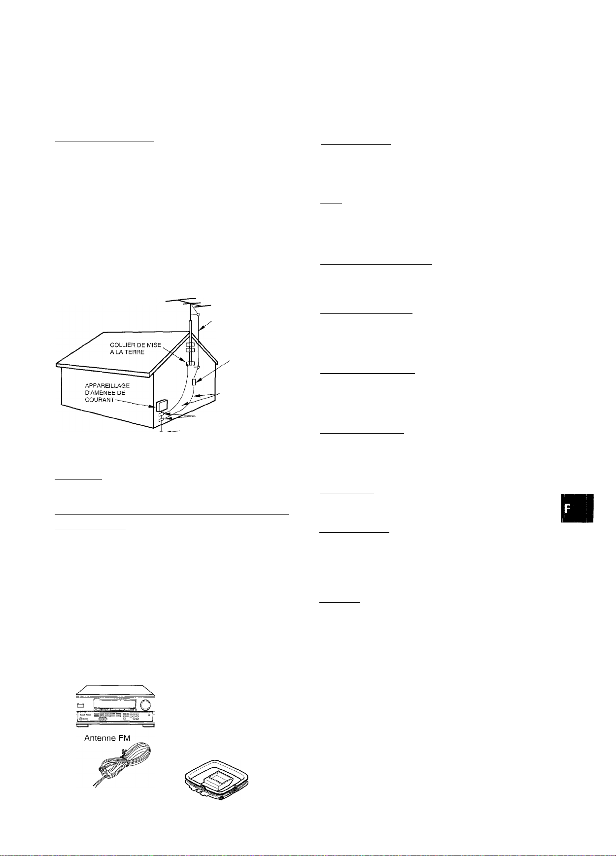
5 Quand l’ampli-tuner n’est pas utilisé — Débranchez l’ampli-
tuner de la prise murale si vous prévoyez de ne pas l’utiliser
pendant plusieurs mois. Quand le cordon est branché, une
petite quantité d’électricité s’écoule vers même s’il est hors
tension.
TABLE DES MATIERES
PRECAUTIONS............................................................... 1
Antenne extérieure
1 Lignes électriques — Quand vous raccordez une antenne
extérieure, assurez-vous qu’elle est suffisamment éloignée
des lignes électriques.
2 Prise de terre de l’antenne extérieure — Assurez-vous que
l’antenne est raccordée correctement à la terre par mesure
de protection contre les pointes de tension et l’accumulation
de charges statiques. L’article 810 du Code Electrique
National, ANSI/NFPA70, fournit des informations pour une
mise à la terre correcte des mâts et supports, la mise à la
terre du fil de connexion à un appareil de décharge, la
dimension de l’appareil de décharge, la connexion des
électrodes de terre et les exigences que doivent remplir les
électrodes de terre.
Mise à la terre d'une antenne selon le code national
d'électrlclté(NEC)
FIL DE DESCENTE D'ANTENNE
UNITE DE DECHARGE
D'ANTENNE
(NEC SECTION 810-20)
CONDUCTEURS DE
MISE ALA TERRE
(NEC SECTION 810-21)
COLLIERS DE MISE A LA TERRE
_ ELECTRODE DE MISE A LA TERRE DE
■ LA LIGNE D'AMENEE DE COURANT
(NEC ARTICLE 250 PARTIE H)
NEC; CODE NATIONAL D'ELECTRICITE
Entretien
Nettoyez l’ampli-tuner comme indiqué dans le mode d’emploi.
Réparations exigeant l’intervention d’un professionnel
Faites réparer l’ampli-tuner par un professionnel dans les cas
suivants:
- Le cordon ou la prise secteur a été endommagé
- Des objets ou liquides sont tombés dans l’ampli-tuner
- L’ampli-tuner a été exposé à la pluie ou à l’eau
- L’ampli-tuner ne semble pas fonctionner correctement
- Les performances de l’ampli-tuner ne sont plus les mêmes
- L’ampli-tuner est tombé ou le coffret a été endommagé
NE PAS ESSAYER DE REPARER SQI-MEME LE RECEPTEUR.
Vérifiez votre appareil et les accessoires
Ampli-tuner stéréo AV-D50 Télécommande
PREPARATIFS______________________________
RACCORDEMENTS
AVANT DE COMMENCER
REGLAGE DE L'HORLOGE..............................................7
..........................................................
................................................
SON_______________________________________
REGLAGE PERSONNEL DU SON.....
EGALISEUR GRAPHIQUE ELECTRONIQUE
PROCESSEUR D'AMBIANCE......................................... 9
OPERATIONS DE BASE
______________________
SELECTION D'UNE SOURCE AUDIO OU VIDEO
ENREGISTREMENT D'UNE SOURCE AUDIO...............11
..............................
............
.....
...........
10
RECEPTION RADIO__________________________
ACCORD MANUEL...................................................... 12
ACCORD DIRECT............................................................12
PREREGLAGE DES STATIONS................................... 13
DOLBY SURROUND
SELECTION DU DOLBY PRO LOGIC
REGLAGE DE LA BALANCE DU NIVEAU DES
ENCEINTES
TELECOMMANDE
FONCTIONNEMENT D’UN TELEVISEUR ORDINAIRE,
TELEVISEUR RACCORDE AU CABLE,
MAGNETOSCOPE OU LECTEUR CD
MINUTERIE
_______________________
REGLAGE DE LA MINUTERIE D'ARRET
GENERALITES
SOIN ET ENTRETIEN..................................................... 17
SPECIFICATIONS........................................................... 18
EN CAS DEPANNE
NOMENCLATURE...........................................................19
ANNEXE
CODES ID DE TELEVISEURS
CODES ID DE DECODEURS
CODES ID DE MAGNETOSCOPES
CODES ID DE LECTEURS CD
___________________________________
_________________________
.......................
................................................................
___________________________
.......................
......................
_________________________
.........................................................
......................................
........................................
..............................
......................................
.....
14
15
16
17
19
A-1
A-2
A-3
A-4
3
7
8
9
Mode d’emploi, etc.
L
Antenne AM
FRANÇAIS
Page 44

PREPARATIFS
RACCORDEMENTS
Avant de raccorder le cordon secteur
La tension nominale de l’ampli-tuner indiquée sur le panneau
arrière est de 120 V. Vérifiez si elle correspond à la tension locaie.
IMPORTANT
Raccordez les enceintes, les antennes et les autres appareils
en premier. Raccordez le cordon secteur en dernier.
Veillez à raccorder la prise VIDEO OUT d’un lecteur DVD
directement à un téléviseur, et non pas à cet appareil, sinon
l’image présentera de la distorsion à la lecture de copie DVD
protégée.
Le son fourni aux prises 5.1 INPUT ne peut pas être enregistré.
Lors de l’enregistrement du son d’un lecteur DVD, raccordez
les prises AUDIO OUT (DOWN MIXING) du lecteur DVD aux
prises VIDEO 1/DVD/MD AUDIO IN de cet appareil.
Pour le raccordement d’un appareil vidéo monophonique,
utilisez un cordon de liaison stéréo-mono (non fourni).
RACCORDEMENT DE TOUT
L'EQUIPEMENT
Les prises et les fiches des cordons de liaison sont codées
couleur de la façon suivante:
Prises et fiches rouges: Canal droit des signaux audio
Prises et fiches blanches: Canal gauche des signaux audio
Prises et fiches jaunes: Signaux vidéo
REMARQUE
Insérez les fiches à fond dans les prises. Des connexions
relâchées peuvent produire un bourdonnement ou d’autres
interférences.
Camescope
à VIDEO PUT .
à AUDIO OUT
Lecteur DVD ou magnétoscope 1/Lecteur MD*^
CZD
© O
1-------------------------1
0 1
..............
Téléviseur
Magnétoscope 2 ou lecteur
TT
1
3 FRANÇAIS
____1 i
-
....
1
à AUDIO IN
, (Magnétoscope 2)
à VIDEO IN (Magnétoscope 2)
L.J!
Il
II
Page 45
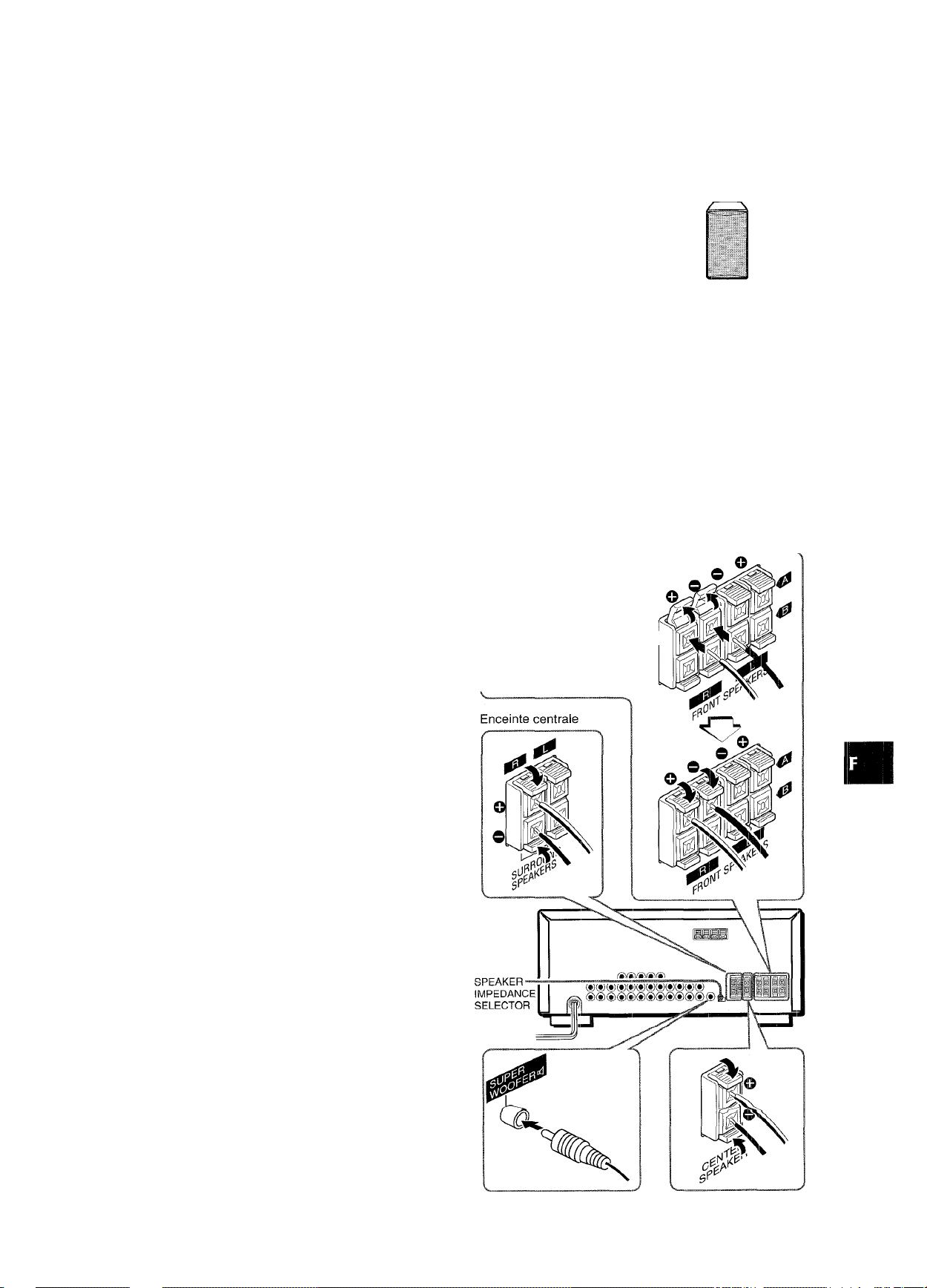
® et (2) sur l’illustration correspondent aux détails suivants.
©Antenne AM ©Antenne FM
©Caisson de grave
®®®@@®®®®®®® I /C
®@®®®®@@®®®®® ^ '
Droite Gauche
©Enceinte surround
RACCORDEMENT DES ENCEINTES ®
Bornes d’enceinte
Raccordez les enceintes avant (systèmes A et/ou B), une
enceinte centrale, des enceintes surround et un caisson de grave
aux prises correspondantes de l’ampli-tuner;
- les cordons d’enceintes avant aux bornes FRONT SPEAKERS
- le cordon d’enceinte centrale aux bornes CENTER SPEAKER
- les cordons d’enceinte surround aux bornes SURROUND
SPEAKERS.
- le cordon du caisson de grave (amplifié, Aiwa TS-W35 etc.) à
la prise SUPER WOOFER “d pour obtenir un son grave
omniprésent.
©Paire d'enceintes A ©Paire d'enceintes B
n
[7
Enceintes avant
Relevez le poussoir de la
borne, insérez le cordon
d’enceinte dans l’orifice,
puis refermez le poussoir.
Vérifiez si le cordon est
bien bloqué.
Droite Gauche Droite Gauche
©Enceinte centrale
i£
<
0.
lU
ir
0.
Impédance des enceintes
• Enceintes avant et arriére
Utilisez des enceintes de même impédance pour les enceintes
avant et arrière.
Le sélecteur SPEAKER IMPEDANCE SELECTOR à l’arrière de
l’ampli-tuner doit être réglé sur la position correspondant à
l’impédance des enceintes avant et centrale.
Pour utiliser des enceintes de 4 ohms, réglez le sélecteur sur
IMP;4ÎI Pour utiliser des enceintes de 8 ohms, réglez-le sur
IMP:8Î2. Débranchez le cordon secteur avant de régler le
sélecteur.
• Enceintes surround et caisson de grave
Le sélecteur SPEAKER IMPEDANCE SELECTOR n’a aucun
effet sur les bornes SURROUND SPEAKERS et la prise SUPER
WOOFER <1. Pour les enceintes surround et le caisson de grave,
utilisez des enceintes d’au moins 8 ohms.
Raccordement des bornes + à + et - à -
Pour obtenir l’effet sonore adéquat, les bornes d’enceintes de
l’ampli-tuner et des enceintes doivent être raccordées
correctement: les bornes + de l’ampli-tuner doivent être reliées
au« bornee -i- dee enesintee (et — à —).
• Veillez à raccorder correctement les cordons comme indiqué
sur l’illustration de droite. Des connexions inadéquates peuvent
causer des courts-circuits au niveau des bornes SPEAKER(S).
• Ne pas laisser de sources de magnétisme près des enceintes.
* •
Enceintes surround
Caisson de grave
FRANÇAIS 4
Page 46
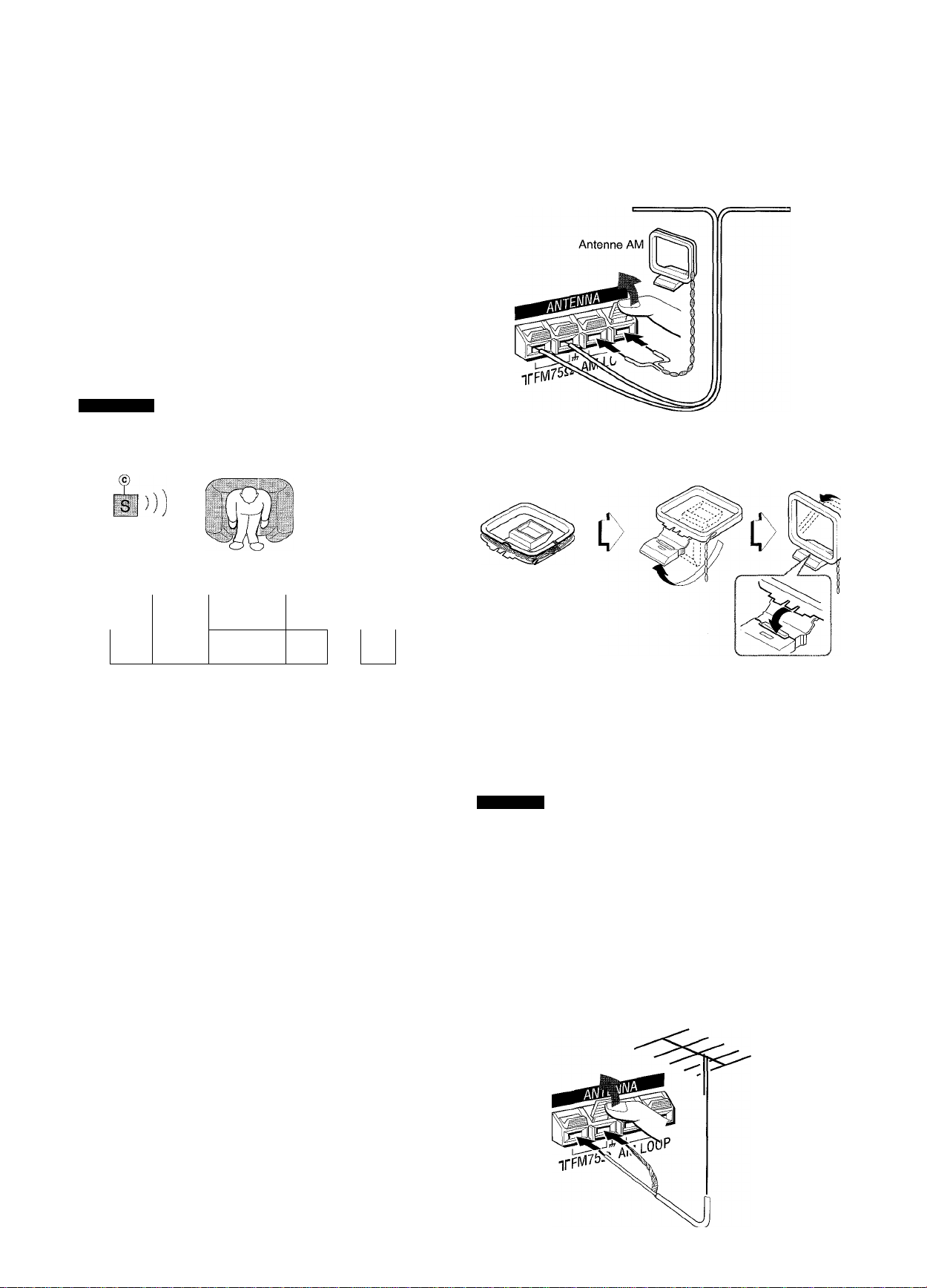
POSITIONNEMENT DES ENCEINTES
Positionnez les enceintes de manière à obtenir les meilleurs
effets Dolby Digital Surround (5.1 CH), Dolby Pro Logic ou DSP.
(D Enceintes avant ® Enceinte centraie
Installez l’enceinte centrale entre les deux enceintes avant
et sur ou sous le téléviseur, si l’ampli-tuner est raccordé à un
téléviseur.
© Enceintes surround
Installez les enceintes surround directement sur les côtés ou
légèrement en retrait de la position d’écoute. Alignez-les
horizontalement à environ 1 m (3,2 pieds) au-dessus du
niveau des oreilles.
(§) Caisson de grave
Installez le caisson de grave quelque part entre les deux
enceintes avant.
REMARQUE
Le son des enceintes surround ou de l’enceinte centrale dépend
du réglage de la fonction DSP, Dolby Pro Logic et 5,1 CH.
S
RACCORDEMENT DES ANTENNES
FOURNIES (D
Raccordez l’antenne FM aux bornes FM 75 Q et l’antenne AM
aux bornes AM LOOP.
Antenne FM
Pour poser i’antenne cadre AM sur une surface
Insérez la saillie dans la rainure comme Indiqué sur l’Ilustration.
—
R "
@
J
.............
----
TV
----
1
® S) @
i
—
CIZ
J
V
L
Pour positionner les antennes
Antenne fil FM:
Etendez-la à l’horizontale de manière à former un T et fixez ses
extrémités au mur.
Antenne cadre AM:
Faites-la pivoter pour trouver la meilleure direction.
REMARQU
• Ne pas approcher l’antenne FM d’objets métalliques ou de
tringles de rideaux.
• Ne pas approcher l’antenne AM d’autres appareils, de l’ampli-
tuner, du cordon secteur ou des cordons d’enceintes, car elle
pourrait capter du bruit.
• Ne pas dérouler le fil de l’antenne cadre AM.
RACCORDEMENT D’UN ANTENNE EXTERIEURE
Pour garantir une réception FM de qualité, il est conseillé d’utiliser
une antenne extérieure. Raccordez l’antenne extérieure aux
bornes FM 75 n.
FRANÇAIS
Page 47

A PROPOS DE LA TELECOMMANDE
Mise en place des piles
Enlevez le couvercle du logement des piles au dos de la
télécommande et insérez deux piles R6 (format AA).
Remplacement des piles
La portée maximale de la télécommande, c’est-à-dire la distance
entre la télécommande et le capteur de l’ampli-tuner, devrait être
de 5 mètres (16 pieds). Quand la portée est réduite, remplacez
les piles par des neuves.
Utilisation de la télécommande
Les instructions de ce mode d’emploi indiquent la plupart du
temps les touches de l’appareil. Les touches de la télécommande
ayant ie même nom que celles de l’appareil peuvent tout aussi
bien être utilisées.
k-'ii i--¿llli
• Si vous prévoyez de ne pas utiliser l’ampli-tuner pendant une
certaine période, enlevez les piles de la télécommande pour
éviter toute fuite de l’électrolyte des piles.
• La télécommande risque de ne pas fonctionner correctement
quand:
- La ligne de vue entre ia télécommande et le capteur de
télécommande dans l’afficheur est exposée à une lumière
intense, par exemple la lumière directe du soleil.
- D’autres télécommandes sont utilisées à proximité
(télécommande de téléviseur, par ex.).
Touche FUNCTION
A chaque pression sur cette touche, la source sonore change
de la façon suivante: FM (ou AM)®’ V3 V2 -■> V1 CD
^AUX-» PHONO.
a): Le nom de la gamme accordée en dernier lieu est affiché.
Touches TUNER PRESET/SURROUND
Elles servent à accorder les stations qui ont été préréglées.
Accordez une station qui a été préréglée sur l’ampli-tuner.
Pour accorder une station supérieure, appuyez sur la touche
►WUP. Pour accorder une station inférieure, appuyez sur la
touche ¡◄◄DOWN.
Cette touche sert aussi à ajuster la balance des niveaux
d’enceintes du mode DSP, Dolby Pro Logic ou 5,1 CH.
SBUADAIie
Il n’est pas nécessaire d’appuyer sur la touche AIW,A RECEIVER
chaque fois que vous faites fonctionner l’ampli-tuner Aiwa, à
moins qu’un autre mode ait été sélectionné. (Voir
“TELECOMMANDE” a la page 16.)
Si l’ampli-tuner ne fonctionne pas avec la
télécommande
Effectuez les étapes suivantes avec la télécommande.
1 Appuyez sur la touche AIWA RECEIVER.
2 Appuyez pendant environ 2,5 secondes sur la
touche SET UP.
Le témoin en haut de la télécommande clignote deux fois
pendant que vous appuyez sur la touche.
3 Appuyez sur les touches DIGIT dans l’ordre de
“4” “o”et “6”.
(/>
cc
<
O.
liJ
tr
a.
Fonctionnement de la télécommande
Cette télécommande vous permet de faire fonctionner d’autres
appareils outre l’ampli-tuner Aiwa. Pour les détails au sujet du
fonctionnement d’un autre appareil à partir de la télécommande,
reportez-vous à “Télécommnade” a la page 16.
Seul le fonctionnement de l'ampli-tuner Aiwa à partir de la
télécommande est expliqué dans ce paragraphe.
■ RECEIVER
KEY
■ TUNER PRESET/
SURROUND
■ VOLUME
1 Appuyez sur la touche AIWA RECEIVER peur
régler la télécommande sur le mode ampli-tuner
Aiwa.
2 Appuyez sur une des touches indiquées ci-
dessus.
FRANÇAIS 6
Page 48

AVANT DE COMMENCER
REGLAGE DE L’HORLOGE
POWER TAPE MONITOR VOLUME
PHONES FRONT SPEAKERS A, B Touches de
fonction
Pour mettre l’ampli-tuner sous tension
Appuyez sur une des touches de fonction (TUNER,
PHONO, AUX, CD, VIDEO 1/5.1 CH, VIDEO 2 ou
VIDEO 3) ou sur la touche TAPE MONITOR.
Quand vous appuyez sur la touche TUNER, la station accordée
en dernier lieu est reçue (Mise en service directe).
Vous pouvez aussi utiliser l’interrupteur POWER.
L’ampli-tuner fonctionne dans les quatre secondes qui suivent,
quand le niveau du volume (VOL) et le nom de la fonction
apparaissent tour à tour et que l’indicateur de la fonction
sélectionnée clignote.
Sélection de la paire d’enceintes avant
Pour utiliser la paire d’enceintes A: Réglez la touche FRONT
SPEAKERS A sur .»ON (marche).
Pour utiliser la paire d’enceintes B: Réglez la touche FRONT
SPEAKERS B sur ».ON (marche).
Pour utiliser les deux paires d’enceintes: Réglez les deux touches
sur »ON (marche).
Réglez ces touches sur J.OFF (arrêt) pour mettre une paire
d’enceintes, ou les deux, hors service.
REMARQUE
Comme les paires d’enceintes avant A et B sont raccordées en
série:
- le son est légèrement réduit quand vous utilisez les deux
paires d’enceintes
- aucun son n’est audible si les touches FRONT SPEAKERS
A et B sont enclenchées (»ON/marche) mais qu’une seule
paire d’enceintes est raccordée
Utilisation d’un casque
Raccordez un casque à fiche standard stéréo (06,3 mm, 1/4
pouce) à la prise PHONES. N’oubliez pas de désactiver les
touches FRONT SPEAKERS A et B ( J.OFF/arrêt), sinon le son
sera fourni par les haut-parleurs.
CLOCK
1,3,5
Û O
Q O O =3
CD CDD
Q L_
..
■
JO
30000 O I - V
2,4
Quand le cordon secteur est raccordé au secteur pour la première
fois, l’horloge clignote sur l’afficheur.
Réglez-la de la façon suivante quand l’ampli-tuner est éteint.
1 Appuyez sur la touche SET.
L’heure clignote.
\ I /
'! ' -
7 1"'"
2 Appuyez sur la touche DOWNT ou UPA pour
désigner l’heure.
3 Appuyez sur la touche SET pour valider l’heure.
L’heure cesse de clignoter et les minutes clignotent.
4 Appuyez sur la touche DOWNT ou UPA pour
désigner ies minutes.
5 Appuyez sur ia touche SET pour vaiider ies
minutes.
Les minutes cessent de clignoter sur l’afficheur et l’horloge
se met en marche à partir de 00 seconde.
Pour remettre l’horloge à l’heure
Appuyez sur l’interrupteur POWER pour mettre l’ampli-tuner hors
tension. Appuyez sur la touche SET et effectuez les opérations
I à 5 ci-dessus.
Pour afficher l’heure actuelle
Appuyez sur la touche CLOCK de la télécommande. L’heure est
affichée pendant 4 secondes.
^acDO
REMARQUE
La fonction 5,1 CM, I0 ôystômô Dôlby Pj*ô Lôcjîe ôu I© ©yçfèmç
DSP sont automatiquement annulés quand vous raccordez un
casque.
Pour éteindre l’ampli-tuner, appuyez sur l’interrupteur POWER.
7 FRANÇAIS
Pour passer au standard de 24 heures
Appuyés sur l'Interrupteur POWER tout en tenant la touche UFA
OU DOWNT enfoncée pendant que l’heure est affichée.
Répétez la même opération pour rétablir le standard de 12
heures.
Si l’affichage de l’heure clignote quand l’ampli-tuner est hors tension
II y a eu une interruption de courant. L’horloge doit être remise à
l’heure.
Si l’alimentation est interrompue pendant plus de 24 heures,
tous les réglages mémorisés après l’achat doivent être de
nouveau effectués.
Page 49

REGLAGE PERSONNEL DU SON
T-E3ASS
VOLUME
SYSTEME SUPER Ï-BASS
Le système T-BASS sert à renforcer le réalisme des basses
fréquences.
Appuyez sur la touche T-BASS.
A chaque pression, le niveau change. Sélectionnez un des trois
niveaux, ou la position d'annulation si vous préférez.
(annulation)
|o
lij
cr
Q.
REGLAGE DE VOLUME
Tournez la commande de volume sur l’ampli-tuner ou appuyez
sur les touches VOLUME de la télécommande.
Le niveau sonore est indiqué sur l’afficheur pendant quatre
secondes. Il peut être réglé de 0 à 31 (MAX) mais il clignote s’il
est réglé au-dessus du niveau 21.
Le niveau du volume reste mémorisé à la mise hors tension de
l’ampli-tuner, mais s’il est réglé au-dessus du niveau 17 il sera
automatiquement réglé au niveau 16 la prochaine fois que vous
mettrez l’ampli-tuner sous tension.
Pour ajuster la balance gauche/droite des enceintes avant
Appuyez sur la touche BALANCE pour afficher “L/R OdB”, puis
appuyez de façon répétée sur la touche DOWNT ou UPA en
l’espace de quatre secondes.
Notez que la balance des enceintes avant des modes 5,1 CH et
Dolby F’ro Logic change également.
Pour couper provisoirement le son
Appuyez sur la touche MUTING (-20 dB).
“MUTE ON’’ apparaît sur l’afficheur pendant quatre secondes.
Quand le son est coupé, l’indicateur de fonction sélectionné
clignote. Appuyez une nouvelle fois sur la touche MUTING pour
rétablir le son.
SYSTEME BBE
REMARQUE
Le son des basses fréquences peut présenter des distorsions
quand le système T-BASS est utilisé avec un disque ou une
cassette sur lesquels les graves sont amplifiés d’origine. Dans
ce cas, mettez le système T-BASS hors service.
REGLAGE DU SON PENDANT L'ENREGISTREMENT
Vous pouvez varier à volonté le volume de sortie et le timbre
des enceintes ou du casque sans changer le niveau
d’enregistrement.
Le système BBE permet d’améliorer la clarté des hautes
fréquences.
Appuyez sur la touche BBE.
A chaque pression, le niveau change. Sélectionnez un des trois
niveaux, ou la position d'annulation si vous préférez.
■aaa—»•■aga-viaaa-
L-ii
REMARQUE
- Le système BBE est automatiquement annulé quand:
- le Dolby Pro Logic est activé
- la fonction 5,1 CH est sélectionnée
• Le système BBE ne peut pas être activé quand la fonction 5,1
CH est sélectionnée.
I (annulation)
FRANÇAIS 8
Page 50

EGALISEUR GRAPHIQUE
PROCESSEUR D’AMBIANCE
ELECTRONIQUE
L’ampli-tuner présente les cinq modes d’égalisation suivants.
__________
GEQ
ROCK: Son puissant avec accentuation des aigus et des graves
POP: Présence améliorée des voix et des médiums
JAZZ: Accentuation des basses fréquences pour ia musique de
type jazz
CLASSIC: Son plus riche avec des graves iourds et des aigus
fins
BGM: Son caime avec graves et aigus supprimés
Appuyez sur une des touches GEQ (égaliseur graphique).
Le nom du mode sélectionné apparaît sur l’afficheur pendant
quatre secondes et ie mode séiectionné sur i’afficheur est entre
parenthèses.
MANUAL
DSP SELECT
MANUAL
SELECT
UPi
□[ J
cjam
aacD
Q a
O O
C^O Oc=3
C DC=D
®CD
■DOWN
■UP^M
Oo CT3
Les circuits du processeur d’ambiance (DSP) peuvent recréer
l’effet de sons réfléchis par les murs et les plafonds, pour simuler
la présence d’un environnement particulier. Il y a quatre modes
d’ambiance avec les modes d’égalisation correspondants. Les
modes d’égalisation sont automatiquement sélectionnés et
peuvent être activés ou désactivés selon vos goûts.
Appuyez sur une des touches DSP (DANCE, LIVE, HALL ou ARENA).
Le nom de mode sélectionné apparaît sur l’afficheur pendant
quatre secondes, puis le mode DSP et le mode GEQ
correspondant restent allumés sur l’afficheur.
Mode DSP sélectionné
Mode sélectionné
Pour annuler le mode sélectionné
Appuyez une nouvelle fois sur la touche. “GEQ OFF” apparaît
sur l’afficheur.
Pour sélectionner le mode avec la télécommande
Appuyez de façon répétée sur la touche GEQ jusqu’à ce que le
mode d’égalisation souhaité apparaisse.
I
Mode GEQ correspondant
........................................................
Quand la source de musique est monophonique
Sélectionnez LIVE pour simuler un effet stéréo. Quand vous
sélectionnez DANCE, HALL ou ARENA, aucun son n’est fourni
par les enceintes surround.
Pour annuler le mode sélectionné
Appuyez une nouvelle fois sur la touche sélectionnée. “DSP QFF”
apparaît sur l’afficheur. Même si vous annulez le mode DSP
sélectionné, le mode GEQ correspondant ou sélectionné reste
actif.
Pour sélectionner le mode avec la télécommande
Appuyez de façon répétée sur la touche DSP jusqu’à ce que le
mode DSP souhaité soit affiché.
Pour ajuster le volume et la balance des enceintes surround
Appuyez deux ou trois fois sur la touche MANUAL SELECT
quand le ayetème DSP eat en aervice pour afficher “S-R OdB"
(pour l’enceinte surround droite) ou “S-L OdB” (pour l’enceinte
surround gauche). Appuyez ensuite de façon répétée sur la
touche DOWNT ou UPA en l’espace de quatre secondes.
Notez que le volume et la balance des enceintes surround des
modes 5,1 CH et Dolby Pro Logic changent également.
REMARQU
' Le système DSP est automatiquement annulé quand:
- le Dolby Pro Logic est activé
- la fonction 5,1 CH est sélectionnée
' Le système DSP ne peut pas être activé quand:
- la fonction 5,1 CH est sélectionnée
- un casque est branché
9 FRANÇAIS
Page 51
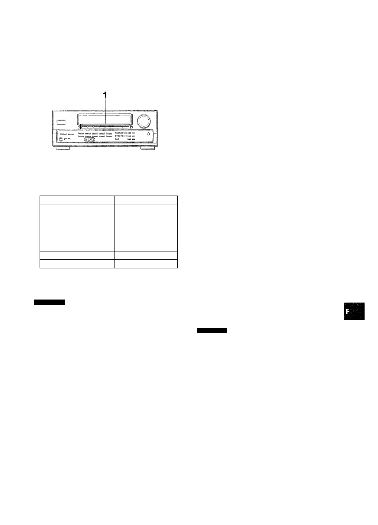
■ii «■
SELECTION D'UNE SOURCE
AUDIO OU VIDEO
1 Sékictionnez la source de programme.
Appuyez sur une des touches de fonction ou la touche TAPE
MONITOR.
Pou' écouter ou regarder Appuyez sur la touche
une cassette
la radio
un disque analogique PHONO
la télévision, etc. AUX
un disque compact CD
une cassette vidéo VIDEO 1/5.1 CH, VIDEO
un LD ou la télévision câble
un MD ou DVD
TAPE MONITOR
TUNER
2, VIDEO 3
VIDEO 2
VIDEO 1/5.1 CH
Pour changer ie nom affiché pour la touche VIDEO 1/5.1 CH et la touche VIDEO 2
Quand vous appuyez sur la touche VIDEO 1/ 5.1 CH, VIDEO 1
apparaît normalement, mais cette indication peut être remplacée
par DVD ou MD.
Quand l’ampli-tuner est sous tension, appuyez sur l’interrupteur
POWER tout en tenant la touche VIDEO 1/5.1 CH enfoncée.
La touche VIDEO 1/5.1 CH fonctionne aussi comme sélecteur
de fonction 5,1 CH (5.1 INPUT). Quand le nom de la fonction
sélectionnée (VIDEQ 1, DVD ou MD) pour la touche VIDEQ 1/
5.1 CH est affiché, appuyez une nouvelle fois sur la touche. Le
nom de la fonction sera “5.1 CH” et la source raccordée aux
prises 5.1 INPUT sera sélectionnée.
Pour rétablir le nom de la fonction sélectionnée, appuyez une
nouvelle fois sur la touche.
Le nom affiché pour la touche VIDEQ 2 peut être remplacé par
VIDEO 2, LD ou TV. Quand l’ampli-tuner est sous tension,
appuyez sur l’interrupteur PQWER tout en tenant la touche
VIDEO 2 enfoncée.
Pour ajuster le niveau sonore de !a source raccordée
Le niveau de sensibilité d’entrée de chaque fonction (sauf
fonctions TUNER et 5,1 CH) peut être ajusté.
Quand le niveau de la source sonore raccordée est plus haut ou
bas que celui de la radio, ajustez-le de la façon suivante.
1 Sélectionnez la fonction dont le niveau doit être
ajusté.
Appuyez sur la touche de fonction correspondante et
reproduisez la source.
2 Appuyez de façon répétée sur la touche UPA ou
DOWNT.
lU
IZü,
OZ
■ no
Q.
'J)
<
ai
U
a
<
ce
LJ
O
Les touches de fonction sur lesquelles il faut appuyer (sauf
PHONO) dépendend de l’appareil raccordé aux prises
d’entrée sur le panneau arrière de l’ampli-tuner.
REMARQUE
Quand vous utilisez un tourne-disque avec amplificateur
égaliseur intégré, réglez l’interrupteur de l’amplificateur égaliseur
sur arrêt. Reportez-vous au mode d’emploi de la platine tournedisque pour les détails.
2 Démarrez la source de programme sélectionnée. 3 Réglez le son.
A propos de la source vidéo fournie au moniteur ou téléviseur
Source vidéo sélectionné
VI ; VIDEO 1, V2: VIDEO 2, V3: VIDEO 3
La source vidéo sélectionnée est indiquée sur l’afficheur et le
signal vidéo transmis par la prise MONITOR VIDEO OUT
apparaît sur le téléviseur.
Le niveau peut être ajusté entre -6dB (MIN) et +8clB (MAX) par
pas de 2dB. Ajustez le niveau de sorte que le son soit au même
niveau que celui de la radio.
nBUABAIie
' Le niveau de sensibilité d’entrée de la fonction TUNER ou 5,1
CH ne peut pas être ajusté.
' Le niveau de TAPE MONITQR ne peut pas non plus être ajusté.
Même si TAPE MONITQR est sélectionné et l’indicateur TAPE
MQNITQR éclairé en rouge, une pression sur la touche UPA
ou DOWNT changera le niveau de la fonction indiquée sur
l’afficheur.
FRANÇAIS
10
Page 52
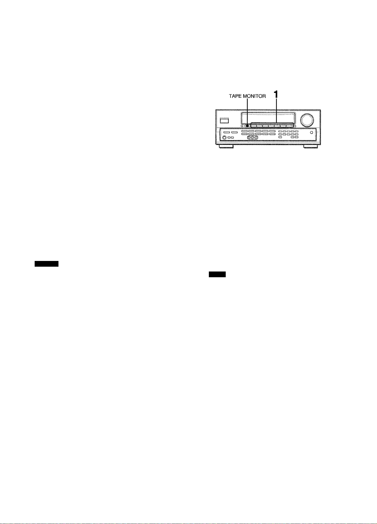
POUR REPRODUIRE UN DVD ENREGISTRE
AVEC LE SYSTEME DOLBY DIGITAL
SURROUND
Cet ampli-tuner a des prises 5.1 INPUT permettant le
raccordement d’un décodeur équipé de prises de sortie 5.1 CH.
SI un lecteur DVD contenant un décodeur Dolby Digital est
raccordé à l’ampll-tuner, vous obtiendrez un son Dolby Digital
Surround comme au cinéma avec les disques enregistrés avec
le système Dolby Digital Surround.
1 Appuyez sur la touche VIDEO 1/5.1 CH pour
sélectionner la fonction VIDEO 1 (DVD ou MD).
2 Appuyez une nouvelle fois sur la touche VIDEO
1/5.1 CH.
“5.1 CH” apparaît sur l’afficheur et le lecteur DVD raccordé
aux prises 5.1 INPUT est sélectionné comme source.
ENREGISTREMENT D’UNE
SOURCE AUDIO
1 Sélectionnez la source de programme qui doit
être enregistrée.
Appuyez sur une des touches de fonction.
2 Mettez la platine à cassette ou l’enregistreur MD
en mode d’enregistrement.
3 Démarrez la source de programme sélectionnée.
3 Démarrez la lecture du DVD raccordé au Dolby
Digital Surround.
Pour rétablir la fonction VIDEO 1, DVD (2 canaux stéréo) ou
MD, appuyez une nouvelle fois sur la touche VIDEO 1/5,1 CH.
REMARQ
> La fonction 5,1 CH est automatiquement annulée et la fonction
VIDEO 1, DVD ou MD sélectionnée quand:
- le Dolby Pro Logic est activé
- un casque est branché
■ La fonction 5.1 CH ne peut pas être sélectionnée quand un
casque est branché.
Pour contrôler le son enregistré pendant l’enregistrement
(quand la platine à cassette raccordée a trois têtes)
Appuyez sur la touche TAPE MONITOR. “TAPE ON” apparaît
sur l’afficheur pendant quatre secondes, puis le nom de la source
sélectionnée à l’étape 1 réapparaît. Pour cesser de contrôler le
son, appuyez une nouvelle fois sur la touche pour que “TAPE
OFF” apparaisse.
ARQU
' Aucun système de contrôle du son n’agit sur l’enregistrement
(voir page 8). .
’ Le son fourni aux prises 5.1 INPUT ne peut pas être enregistré.
Pour l’enregistrement du son d’un lecteur DVD, raccordez les
prises AUDIO OUT (DOWN MIXING) du lecteur DVD aux prises
VIDEO 1/DVD/MD AUDIO IN de l’ampli-tuner.
’ Lors de l’enregistrement d’une source avec l’enregistreur MD
raccordé aux prises VIDEO 1/DVD/MD AUDIO OUT,
sélectionnez la source après avoir appuyé sur la touche VIDEO
2 ou VIDEO 3 (V2 ou V3 doit apparaître).
L’enregistrement ne peut pas être effectué quand l’indication
VI est affiché.
■ Le son fourni par la platine à cassette raccordé aux prises TAPE
MONITOR IN ne peut pas être enregistré.
11
FRANÇAIS
Page 53
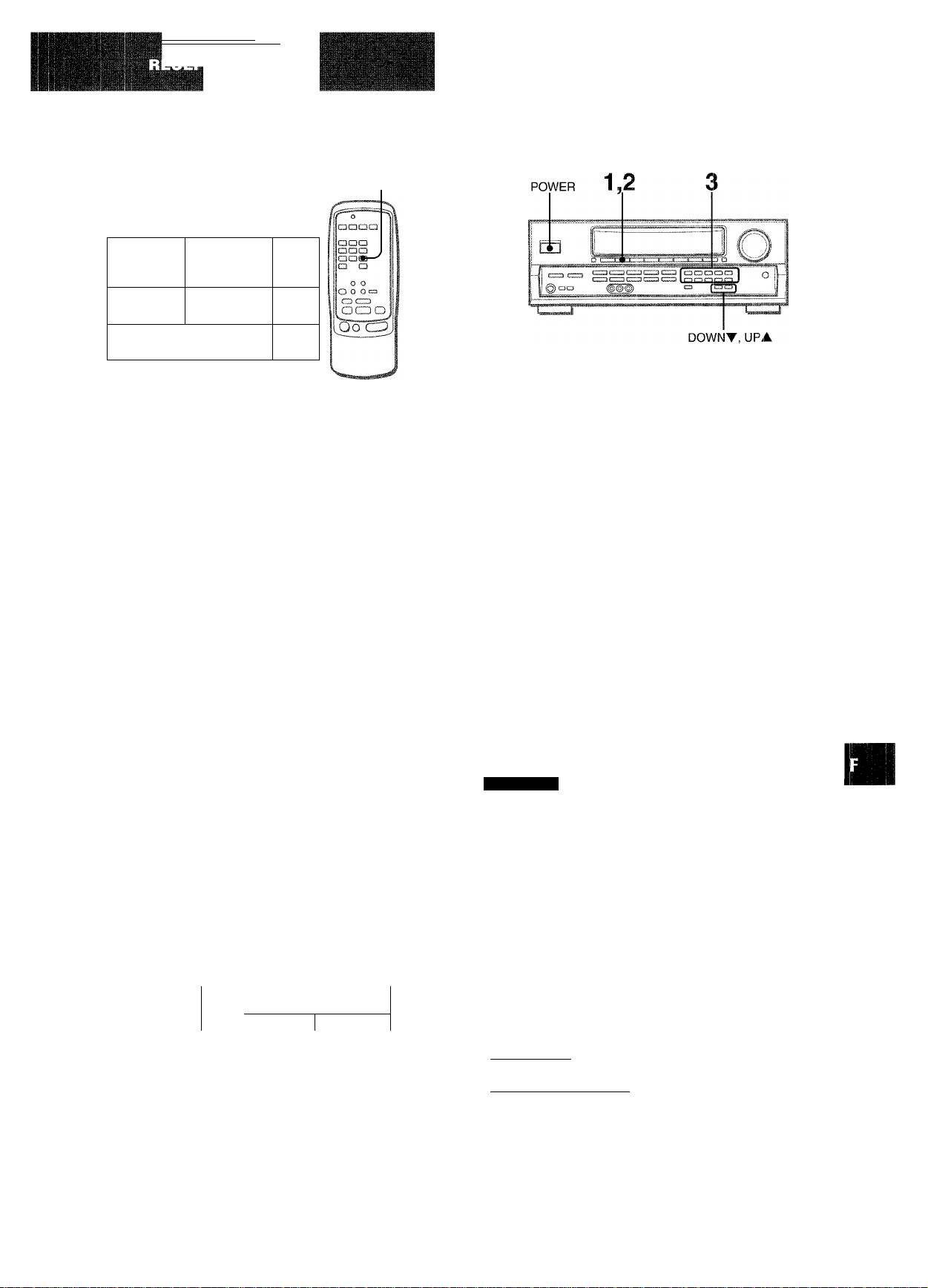
Ml—l
ACCORD MANUEL
MONO
TUNER
)
IE3
! .0.&1
L©°° « -„.„°
crzs ooocac
Appuyez de façon répétée sur la touche TUNER
pour sélectionner la gamme souhaitée.
FM
La fréquence est indiquée après le nom de la gamme et de la
source vidéo (VI, V2 ou V3) pendant deux secondes.
Si vous appuyez sur la touche TUNER quand l’ampli-tuner
est éteint, il se met sous tension.
-------
O
L.I!
► AM —I
ACCORD DIRECT
Si vous connaissez la fréquence de la station souhaitée, vous
pouvez l’accorder directement.
1 Appuyez sur la touche TUNER pour sélectionner
une gamme.
2 Appuyez sur la touche TUNER et maintenez-la
enfoncée jusqu’à ce que “
l’afficheur (Mode d’accord direct).
...........
” clignote sur
lu
<o
iS Q
!JU<
qd:
U)’Z
zQ
OH
iza.
!? ui
ujuJ
O
Appuyez sur ia touche UPA ou DOWNT pour
séiectionner une station.
A chaque pression sur la touche, la fréquence change.
Quand vous recevez une station, “TUNE” est affiché pendant
deux secondes. Pendant la réception stéréo FM, (li®H) est
affiché.
Pour rechercher rapidement une station (recherche automatique)
Appuyez en continu sur la touche UPA ou DOWNT jusqu’à ce
que la recherche commence. Quand une station est accordée,
la recherche s’arrête.
Pour arrêter la recherche automatique, appuyez sur la touche
UPA ou DOWNT.
• La recherche automatique peut ne pas s’arrêter sur les stations
dont le signal est trop faible.
Quand une émission FM stéréo est parasitée
Appuyez sur la touche MONO TUNER de la télécommande pour
que “MONO” apparaisse sur l’afficheur.
Le bruit est réduit, mais la réception est monophonique.
MONO
^ DANCF. LIV
Pour rétablir la réception stéréo, appuyez sur la touche pour
que “MONO” disparaisse.
..........
V*-
3 Appuyez sur les touches numériques
appropriées pour accorder la station souhaitée.
Par exemple:
Pour faire l’accord sur 106,50 MHz, appuyez sur les touches
1,0, 6, 5et0.
Pour faire l’accord sur 95,20 MHz, appuyez sur les touches
9, 5, 2 et 0.
Pour annuler le mode d’accord direct
Appuyez sur la touche UPA ou DOWNT.
REMARQUE
' Quand vous entrez une fréquence hors de la plage d’accord,
la valeur clignote sur l’afficheur pendant deux secondes puis
s’éteint. Vérifiez la fréquence et refaites l’opération 3
correctement.
' Si vous entrez une fréquence non couverte par l’intervalle
d’accord, la valeur est automatiquement arrondie au chiffre
inférieur ou supérieur le plus proche.
' Les touches DIGIT de la télécommande ne peuvent pas être
utilisées pour accorder une station.
Pour changer l’intervalle d’accord AM
Le réglage par défaut de l’intervalle d’accord AM est de 10
kHz. Si vous utilisez cet ampli-tuner dans un pays où
l’attribution des fréquences est de 9 kHz, changez l’intervalle
d’accord.
Tout en tenant la touche TUNER enfoncée, appuyez
immédiatement sur l’interrupteur POWER. Notez que l’ampli-
tuner passe au mode d’accord direct si vous appuyez pendant
une demi-seconde environ sur la touche TUNER.
Pour revenir à l’intervalle initial, refaites les mêmes opérations.
FRANÇAIS 12
Page 54

PREREGLAGE DES STATIONS
ACCORD DES STATIONS PREREGLEES
1 Appuyez sur la toucheTUNER pour sélectionner
une gamme.
/f-ï—^
aoQ
aoa
aaa
a a
O O
c^o O
c ? c:
(1) CD
•DOWN
■UP^M
Oo
2 1
L’ampli-tuner peut mémoriser en tout 32 stations. Quand une
station est mémorisée, un numéro de prérégiage est affecté à
cette station. Utilisez le numéro de préréglage pour accorder
directement la station préréglée.
1 Appuyez sur la touche TUNER pour sélectionner
la gamme et sur la touche UPA ou DOWNT pour
sélectionner une station. Vous pouvez aussi
utiliser i’accord direct.
2 Appuyez sur la touche SET pour mémoriser la
station.
Un numéro de préréglage est affecté à la station, à compter
de 1 dans l’ordre consécutif pour chaque gamme, et clignote
dans l’afficheur pendant deux secondes.
2 Appuyez sur les touches numériques pour
sélectionner une station préréglée.
Par exemple:
Pour sélectionner le numéro de préréglage 25, appuyez sur
2 et 5.
Pour sélectionner le numéro de préréglage 7, appuyez sur 0
et 7.
Pour supprimer une station préréglée
Sélectionnez le numéro de préréglage de la station que vous
voulez supprimer. Appuyez ensuite sur la touche SET puis, dans
les quatre secondes, une nouvelle fois sur la touche SET.
Les numéros de préréglage de toutes les stations de la gamme,
supérieurs au numéro annulé diminuent d’une unité.
Quand vous utilisez la télécommande
Appuyez sur UP^W ou DOWNM^ pour sélectionner un
numéro de préréglage.
REMARQUE
Les touches DIGIT de la télécommande ne peuvent pas être
utilisées pour la sélection d’un numéro de préréglage.
i/^z, tlASS;
/|\
3 Refaites les opérations 1 et 2.
Il n’est pas possible de prérégler une nouvelle station si 32
stations sont déjà mémorisées pour toutes les gammes.
REMARQU
Quand vous changez l’intervalle d’accord AM, toutes les stations
préréglées sont supprimées. Vous devez les prérégler une
nouvelle fois.
13 FRANÇAIS
Page 55
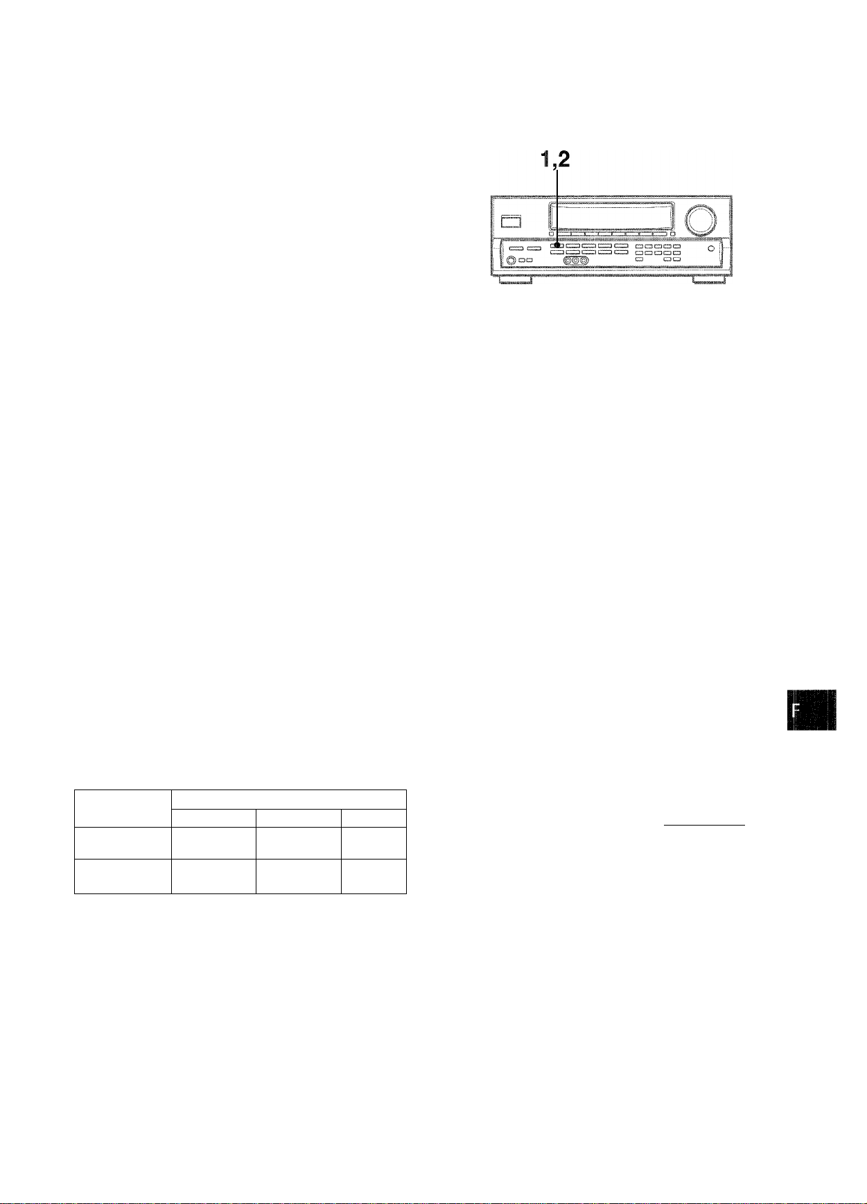
Cet appareil est équipé d’un décodeur Dolby Pro Logic et
supporte aussi un décodeur Dolby Digital équipé de prises 5.1
CH.
L’ampli-tuner combiné aux enceintes surround et à l’enceinte
centrale (standard) assurent un véritable son cinématographique.
A la lecture de disques ou cassettes vidéo enregistrés avec le
système Dolby Pro Logic ou Dolby Digital Surround, un son
extrêmement réaliste enveloppe l’auditeur et crée un
divertissement audiovisuel inédit.
Le réglage indépendant des cinq canaux permet à l’auditeur de
bénéficier d’un son tel que l’on peut en faire l’expérience au
cinéma. Les voix sont reproduites par le champ sonore avant et
central, tandis que l’ambiance, par exemple bruits de voitures
ou de la foule, enveloppe de toute part et recrée une atmosphère
incroyablement réaliste. Veuillez lire attentivement ce qui suit
pour “accorder” la sortie du système en fonction des
caractéristiques de votre salle d’écoute.
Vérifiez les points suivants;
•Avant d’écouter le son DOLBY SURROUND, ajustez
correctement la balance des niveaux d’enceintes (voir page
15).
• Assurez-vous que les enceintes ont été raccordées et installées
correctement (voir pages 3,4 et 5).
• Assurez-vous que le téléviseur et l’appareil vidéo sont raccordés
correctement (voir page 3).
• Assurez-vous que le disque ou la cassette vidéo, etc. sont
enregistrés avec le système Dolby Pro Logic ou Dolby Digital
Surround.
POUR SELECTIONNER UN MODE DOLBY PRO LOGIC
Appuyez de façon répétée sur la touche DOLBY
SURROUND pour sélectionner le mode approprié.
Quand vous sélectionnez le mode DOLBY PRO LOGIC ou 3
STEREO, l’indicateur s’allume et le nom du mode sélectionné
défile sur l’afficheur. A chaque pression sur la touche, le mode
change de la façon suivante.
DOLBY PRO LOGIC
DOLBY PRO LOGIC OFF (annulation)
r
-------
► 3 STEREO
a
ii
''■a:
Z ÛC
0=5
î=ü:
11. >
lU a:
:.} ..J
iU O
iro
SELECTION DU DOLBY PRO
LOGIC
Le mode Dolby Pro Logic optimal dépend du type et de
remplacement des enceintes. Il est conseillé d’utiliser les
enceintes optionnelles Aiwa pour tous les canaux, par exemple,
c’est-à-dire les SX-R2500 comme enceintes surround, la SX-
C2500 comme enceinte centrale et les SX-AV2500 comme
enceintes avant. Sélectionnez le mode Dolby Pro Logic en
fonction de la configuration de vos enceintes.
Mode conseillé
Enceinte centrais
Grande dimension
Enceintes surround
(enceintes arrière)
Sans enceintes
surround
Mode PHANTOM: Sélectionnez ce mode si vous ne raccordez
pas d’enceinte centrale. Les signaux du canal central sont
redistribués sur les enceintes avant gauche et droite.
Mode 3 STEREO: Sélectionnez ce mode si vous ne raccordez
pas d’enceintes surround.
DOLBY PRO
LOGIC-WIDE
3 STEREO
WIDE
Petite dimension
DOLBY PRO
LOGIC-NORMAL
3 STEREO
NORMAL
Sans enceinte
PHANTOM
-
2 Appuyez une nouvelle fois sur la touche DOLBY
SURROUND et tenez la touche enfoncée jusqu’à
ce que le mode d’enceinte centrale que vous
voulez sélectionner apparaisse.
Quand vous sélectionnez le mode DOLBY PRO LOGIC à l’étape 1 :
“NORMAL”, “WIDE” et “PHANTOM” apparaissent tour à tour
sur l’afficheur.
Quand vous sélectionnez le mode 3 STEREO à l’étape 1:
“NORMAL” et “WIDE” apparaissent tour à tour sur l’afficheur.
':ü
• Selon la source sonore ou les conditions d’écoute, vous
n’obtiendrez peut-être pas d’effet surround bien que le Dolby
Pro Logic ait été activé.
• L’effet Dolby Pro Logic ne peut pas être obtenu avec les
enregistrements ne portant pas le logo □□|o°i.BYsumiiuBiD|. utilisez
à la place le système surround DSP (voir page 9).
• Le système Dolby Pro Logic est automatiquement annulé
quand:
- le système BBE ou DSP est activé
- la fonction 5,1 CH est sélectionnée
- un casque est branché
• Le système Dolby Pro Logic ne peut pas être activé quand un
casque est branché.
FRANÇAIS 14
Page 56
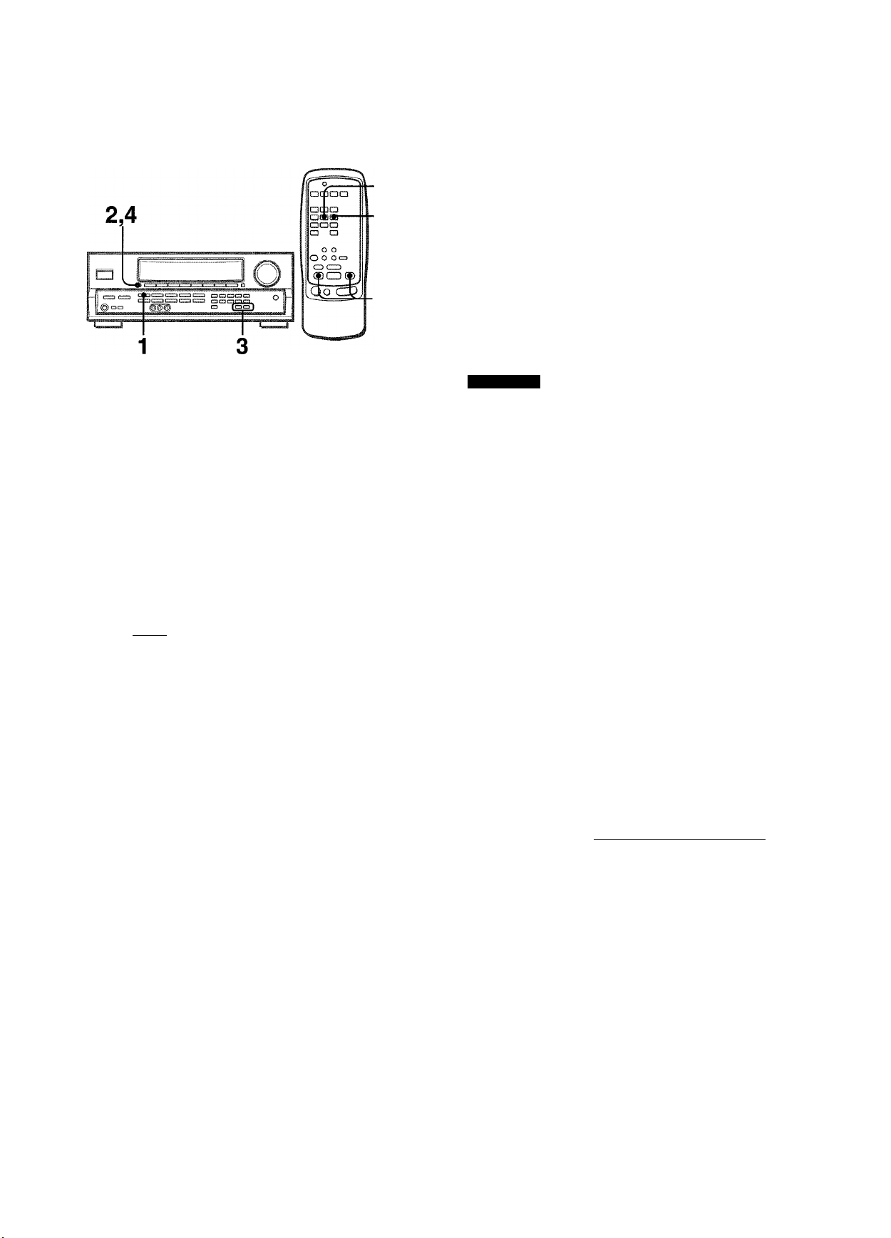
REGLAGE DE LA BALANCE DU NIVEAU DES ENCEINTES
1
2,4
■UP»
DOWNI
Ajustez le niveau sonore de l’enceinte centrale
et des enceintes surround.
Quand “CEN”, “S-L” ou “S-R” clignote sur l’afficheur, appuyez
sur la touche UPA ou DOWNT pour que le niveau sonore
de l’enceinte centrale ou des enceintes surround corresponde
à celui des enceintes avant.
^ / I
La balance des enceintes avant peut être également ajustée
quand “L/R” est affiché.
4 Appuyez une nouvelle fois sur la touche MANUAL
SELECT pour arrêter le signal.
L’ampli-tuner intègre un générateur de signaux d’essai appelé
séquenceur de bruit pour faciliter le réglage de la balance des
cinq canaux.
Le séquenceur fournit un signal qui passe d’un canal à l’autre,
permettant ainsi d’effectuer simplement un réglage du niveau
sonore pour obtenir le même niveau apparent pour chaque canal
à la position d’écoute.
1 Sélectionnez le mode Dolby Pro Logic en fonction
de la configuration actuelie des enceintes.
(Voir page 14.)
2 Appuyez sur ia touche MANUAL SELECT et tenez-
ia enfoncée pendant environ deux secondes
jusqu’à ce que “L/R OdB ’’ apparaisse.
¡nr-'-T-rrr ! 1 .L -¡ÎL^ ■ ■ ■ ■ •■ ■
' I '
Un signal est envoyé à chaque canal dans l’ordre suivant:
Mode DOLBY PRO LOGIC NORMAL ou WIDE
I
L/R OdB (Enceinte avant droite)*’
I
CEN OdB (Enceinte centrale)
REMARQUE
• La touche UP^W ou DOWNM^ de la télécommande peut
être utilisée à l’étape 3 pour le réglage de la balance des
enceintes avec le bruit rose.
• Lors du réglage de la balance des niveaux d’enceintes dans le
mode Dolby Pro Logic, lésa niveaux des modes DSP et 5,1
CH changent aussi.
A propos des canaux
Les enceintes gauche et droite créent l’effet stéréo.
L’enceinte centrale permet d’obtenir un positionnement plus
précis du son sur un large champs sonore.
Les enceintes surround arrière augmentent la “profondeur” du
champ sonore.
Pour changer le temps de retard des enceintes surround
du mode Dolby Pro Logic
Les enceintes surround reproduisent le son une fraction de
seconde après les enceintes avant. Le retard est initialement
réglé sur 20 ms (millisecondes).
Pour changer le temps de retard standard, appuyez de façon
répétée sur la touche MANUAL SELECT pour que “SUR” soit
affiché. Appuyez ensuite sur UPA ou DOWNT. A chaque
pression sur une de ces touches, le temps de retard change
comme suit.
"l" I '■■■.
L/R OdB (Enceinte avant droite)*’
I
S-R OdB (Enceinte surround droite)*^
S-L OdB (Enceinte surround gauche)*^
I
______________________
Mode DOLBY PRO LOGIC PHANTOM
-----
S-l
L/R OdB*’
3-R OdB*"-«
•L/R OdB*i—► L/R OdB*’-
I—►L/R
I
-----
S-L(
Mode 3 STEREO NORMAL ou WIDE
■ L/R OdB*'—►CEN OdB —► L/R OdB*’
------
1
---
1
□
*1 «[_>’ «P” clignote pour indiquer l’enceinte avant d’où sort le bruit
rose.
*^ Le bruit rose est fourni en même temps par les enceintes surround
gauche et droite.
15 FRANÇAIS
|->-15ms ■<-» 20 ms-«—>■ 30ms
Pour ajuster la balance des niveaux d’enceintes pendant l’écoute de la source (modes Dolby Pro Logic et 5,1 CH)
La balance des niveaux d’enceintes peut être changée après le
réglage avec le séquenceur de bruit rose. La balance peut être
réglée à chaque mise en service du système Dolby Pro Logic
ou sélection de la fonction 5,1 CH.
1 Reproduisez un disque ou une cassette vidéo enregistré avec
le Dolby Pro Logic ou Dolby Digital Surround.
2 Appuyez de façon répétée sur la touche MANUAL SELECT
pour que “L/R”, “CEN”, “S-L” ou “S-R” apparaisse sur
l’afficheur.
3 Appuyez sur la touche UPA ou DOWNT pendant que le
nom de l’enceinte que vous voulez régler est affiché.
Dans ce cas, la touche UP^W ou DownM^ de la
télécommande peut aussi être utilisée.
Page 57

TELECOMMAND
FONCTIONNEMENT D’UN TELEVISEUR ORDINAIRE, TELEVISEUR RACCORDE AU CABLE, MAGNETOSCOPE OU LECTEUR CD
Avec la télécommande, vous pouvez aussi faire fonctionner un
téléviseur, un téléviseur raccordé au câble, magnétoscope et
lecteur CD.
POUR ENTRER LE CODE ID D’UN APPAREIL EXTERIEUR
Indicateur-
MODE SELECT ■
aaaa
ZjlZTQ
aa
CDOQ
Q| Q
CD CCD
0CZ)0
. Touches DIGIT
(0-9)
■ SET UP
Oo CD
Pour vérifier le code ID programmé
Vous pouvez vérifier le code ID en comptant le nombre de
clignotements de l'indicateur.
1 Appuyez sur la touche TV, CABLE, VCR ou CD.
Par exemple, pour vérifier le code programmé pour un lecteur
CD, appuyez sur CD.
2 Appuyez pendant environ 2,5 secondes sur la touche SET
UP.
3 Appuyez sur “9”, “9” et “0”. 4 Appuyez sur “1 ” et comptez le nombre de clignotements
de l'indicateur.
Par exemple, si le code “157” a été programmé.
L’indicateur clignote une fois.
5 Appuyez sur “2” et comptez le nombre de clignotements
de l'indicateur.
L’indicateur clignote cinq fois.
6 Appuyez sur “3” et comptez le nombre de clignotements
de l'indicateur.
L’indicateur clignote sept fois.
POUR FAIRE FONCTIONNER UN
TELEVISEUR, DECODEUR, MAGNETO
SCOPE ET LECTEUR CD
^iij
OQ
OZ
~l<
o|
DCS
11.0
>o
ajLu
g
Avant d’essayer de faire fonctionner un appareil eztérieur vous
devez programmer son code ID sur la télécommande de la façon
suivante.
1 Vérifiez le code ID de l'appareil extérieur.
Reportez-vous à le liste de codes ID dans “ANNEXE” à la fin
de ce manuel.
2 Appuyez sur la touche TV, CABLE, VCR ou CD
dans la section MODE SELECT.
3 Appuyez pendant environ 2,5 secondes sur la
touche SET UP.
Assurez-vous que l’Indicateur clignote deux fois quand vous
appuyez sur la touche SET UP.
4 Appuyez sur les trois touches DiGiT qui
correspondent au code ID de l’appareil extérieur.
Par exemple, si le lecteur CD est un modèle AIWA, qui a le
code ID 124 ou 157, appuyez sur les touches DIGIT “1”, “2”
et “4” (ou “1”, “5” et “7”) dans l’ordre.
Quand vous appuyez sur la troisième touche DIGIT,
l’indicateur clignote deux fois pour indiquer que le code ID
est correct et programmé dans la télécommande.
CHANNEL-
MODE SELECT ■
POWER
■ VOLUME
■ Touches DIGIT
(0~9) et ENTER
VCR/CD
ll:Pause,H: Arrêt,
Rembobinage,
►: Lecture,
►W: Avance rapide
1 Appuyez sur une touche de la section MODE
SELECT (TV, CABLE, VCR ou CD)
La télécommande est prête pour faire fonctionner l’appareil
du mode sélectionné.
2 Appuyez sur une des touches indiquées ci-
dessous.
Pour l’utilisation des touches numériques (0 à 9) et ENTEF1,
reportez-vous au mode d’emploi fourni avec l’appareil à contrôler.
Les autres touches mentionnées ci-dessus ont les mêmes
fonctions que celles de l’appareil à contrôler.
la'TXti'F
• Réentrez le code ID de l’appareil extérieur après avoir remplacé
les piles de la télécommnade.
• S’il existe plusieurs codes ID pour l’appareil extérieur dans
“ANNEXE”, essayez d’entrer les codes ID les uns après les
autres jusqu’à ce que parveniez à faire fonctionner l’appareil.
FRANÇAIS 16
Page 58

MINUTERIE
■
GENERALITES
REGLAGE DE LA MINUTERIE D’ARRET
L’ampli-tuner peut être automatiquement mis hors tension à une
heure précise.
1 Appuyez sur la touche AIWA RECEIVER. 2 Appuyez sur la touche SLEEP.
SLEEP ilsi
SOIN ET ENTRETIEN
Un entretien occasionnel de l’ampli-tuner est indispensable pour
garantir des performances optimales.
Pour nettoyer le coffret
Utilisez un chiffon doux et sec.
Si la surface est extrêmement sale, utilisez un chiffon légèrement
imprégné d’une solution détergente neutre. Ne pas utiliser de
solvants puissants, tels que l’alcool, la benzine et du diluant,
car ils pourraient abîmer la finition.
L’appareil se mettra hors tension dans ies 60 minutes qui
suivent.
Pour désigner le temps de fonctionnement jusqu’à la mise hors tension
Appuyez plusieurs fois de suite sur la touche UPA et DOWNT
de l’appareil dans les quatre secondes qui suivent l’étape 2.
A chaque pression sur la touche, le temps change par incréments
de 5 minutes de 5 à 240 minutes.
Temps désigné
Pour vérifier le temps restant jusqu’à la mise hors tension
Appuyez une fois sur la touche SLEEP. Le temps restant est
affiché pendant quatre secondes.
Pour arrêter la minuterie
Appuyez deux fois sur la touche SLEEP pour que “SLEEP”
disparaisse de l’afficheur.
REMARQUE
La touche UP^W ou DOWNM^ de la télécommande ne peut
pas être utilisée pour désigner le temps de fonctionnement
jusqu’à la mise hors tension. Utilisez les touches de l’appareil.
17 FRANÇAIS
Page 59

SPECIFICATIONS
Section Tuner FM
Plage d’accord 87,5 MHz à 108 MHz
Sensibilité utilisable 13,2 dBf
(IHF)
Bornes d’antenne 75 ohms (asymétrique)
Section Tuner AM
Plage d’accord
Sensibilité utiiisable
Antenne
Section Amplificateur
Puissance de sortie
Distorsion harmonique
totale
Entrées
Sorties
530 kHz à 1710 kHz (intervalle de 10
kHz), 531 kHz à 1602 kHz (intervalle
de 9 kHz)
350 ^iV/m
Antenne cadre
[Mode stéréo]
Avant
130 watts par canal, minimum RMS à
8 ohms, de 40 Hz à 20 kHz, avec
moins de 0,9 % de distorsion
harmonique totale
[Mode Dolby Pro Logic ou 5,1 CH]
Avant
120 watts par canal, minimum RMS à
8 ohms, de 40 Hz à 20 kHz, avec
moins de 0,9 % de distorsion
harmonique totale
Arrière (Surround)
60 watts par canal, minimum RMS à 8
ohms, 1 kHz, avec moins de 0,9 % de
distorsion harmonique tetale
Centre
120 watts, minimum RMS à 8 ohms, 1
kHz, avec moins de 0,9 % de
distorsion harmonique totale
0,08 % (85 W, 1 kHz, 8 ohms.
Enceintes avant)
AUDIO IN
PHONO: 2,5 mV, réglable (47
kohms)
CD: 250 mV, réglable (47 kohms)
TAPE MONITOR: 350 mV (47
kohms)
VIDEO 1/DVD/MD, VIDEO 2/LD/
TV, VIDEO 3, AUX: 250 mV,
réglable (47 kohms)
5.1 INPUT
FRONT, CENTER: 560 mV (47
kohms)
SURROUND, SUB-WOOFER:
400 mV (47 kohms)
VIDEO IN: 1 Vc-c (75 ohms)
AUDIO OUT (REC OUT): 200 mV (1
kohm)
VIDEO OUT (MONITOR): 1 VC-C (75
Ohms)
SUPER WOOFER: 1,2 V
FRONT SPEAKERS IMP: 80/4i2
au Choix (enceintes avant A et B):
avec SPEAKER IMPEDANCE
SELEGTOn réglé aur 4S2, aoGepto
des enceintes de 4 ohms
avec SPEAKER IMPEDANCE
SELECTOR réglé sur 80, accepte
des enceintes de 8 ohms ou plus
SURROUND SPEAKERS IMP: 80
(enceintes surround): accepte des
enceintes de 8 ohms ou plus
CENTER SPEAKER IMP: 80/40 au
choix
avec SPEAKER IMPEDANCE
SELECTOR réglé sur 40, accepte
des enceintes de 4 ohms,
avec SPEAKER IMPEDANCE
SELECTOR réglé sur 80, accepte
des enceintes de 8 ohms ou plus.
PHONES (jack stéréo): accepte un
casque de 32 ohms ou plus
Coupure du son
-20 dB
Généralités
Alimentation
Consommation
Dimensions (l/h/p)
Poids
La conception et les spécifications peuvent être modifiées sans
préavis.
HUE SYSTEM
Le mot “BBE” et le logo “BBE SYSTEM” sont des marques de
BBE Sound, Inc.
Sous licence de BBE Sound, Inc.
DOLBY PRO LOGIC
Fabriqué sous licence de Dolby Laboratories Licensingi
Corporation.
“DOLBY”, le symbole du double D □□ et “PRO LOGIC” sont des
marques de fabrique de Dolby Laboratories Licensinçi
Corporation.
Secteur 120 V, 60 Hz
230 W
430 X 155 X 351 mm (17 X 6Vb x 13%
po.)
11,2 kg (24 li. 11 on.)
lU Uj
■■aiE
^ LU
W
ü
FRANÇAIS 18
Page 60

EN CAS DE PANNE
NOMENCLATURE
Si l’ampli-tuner ne fonctionne pas comme décrit dans le mode
d’emploi, vérifiez les points suivants.
GENERAL
Aucun son.
• Est-ce que le cordon secteur est raccordé correctement?
• Est-ce qu’un raccordement n’est pas exact? (-► page 3)
• Est-ce qu’il y a un court-circuit au niveau des bornes
d’enceintes?
-» Débranchez le cordon secteur, puis raccordez correctement
l’enceinte.
• Est-ce que vous avez appuyé sur une mauvaise touche?
• Est-ce que les touches FRONT SPEAKERSAet B sont réglées
correctement? (-» page 7)
Son émis par une enceinte seuiement.
• Est-ce que la balance BALANCE est réglée correctement ?
• Est-ce que l’autre enceinte est débranchée ?
Le voiume sonore est considérabiement réduit.
• Est-ce que vous avez appuyé sur la touche MUTING?
Affichage erroné ou dysfonctionnement.
-> Réinitialisez l’ampli-tuner comme indiqué ci-dessous.
SECTION TUNER
Parasites éiectrostatiques constants.
• Est-ce que l’antenne est correctement raccordée? (-► page 5)
• Est-ce que le signal FM est faible?
-* Raccordez une antenne extérieure.
La réception contient des interférences ou ie son
présente de ia distorsion.
• Est-ce que la chaîne capte du bruit ou est-ce qu’il y a des
interférences par trajets multiples?
-► Changez l’orientation de l’antenne.
-* Eloignez l’ampli-tuner des autres appareils électriques.
Pour réinitialiser l’ampli-tuner
Si l’affichage ou le fonctionnement n’est pas normal, réinitialisez
l’ampli-tuner de la manière suivante.
1 Appuyez sur l’interrupteur POWER pour mettre l’ampli-tuner
hors tension.
2 Appuyez sur l’interrupteur POWER tout en tenant la touche
SET enfoncée. Tous les préréglages sont effacés.
Si vous ne pouvez pas mettre îampli-tuner hors tension à l’étape
1 parce qu’il ne fonctionne pas normalement, réinitialisez-le en
débranchant le cordon secteur et refaites l’opération 2.
Les instructions concernant chaque touche de l’ampli-tuner ou
la télécommande se trouvent aux pages indiquées ci-dessous.
Commandos
AIWA RECEIVER
AUX
BALANCE
6BE
CD
CLOCK
DOLBY SURROUND
DOWNT (!◄◄) 7, 9, 10, 12, 13, 15, 17
DSP
FRONT SPEAKERS A, B
FUNCTION
GEQ
MANUAL SELECT (TEST)
MONO TUNER
MUTING, MUTE
PHONES
PHONO
POWER
SET
SETUP
SLEEP
SPEAKER IMPEDANCE
SELECTOR
TAPE MONITOR
T-BASS
TUNER, BAND DIRECT
TUNER PRESET/SURROUND
UP A (►►!)
VIDEO 1/5.1 CH
VIDEO 2
VIDEOS
VOLUME (V, y\)
Pages
6,17
7,10
8
8
7, 10
7
14, 15
9
7
6
9
9, 15
12
8
7
7, 10
7, 12
7, 13
16
17
4
7, 10, 11
8
7, 10, 12, 13
6
7, 9, 10, 12, 13, 15, 17
7, 10,11
7, 10
7, 10
8, 16
19 FRANÇAIS
Page 61

Page 62
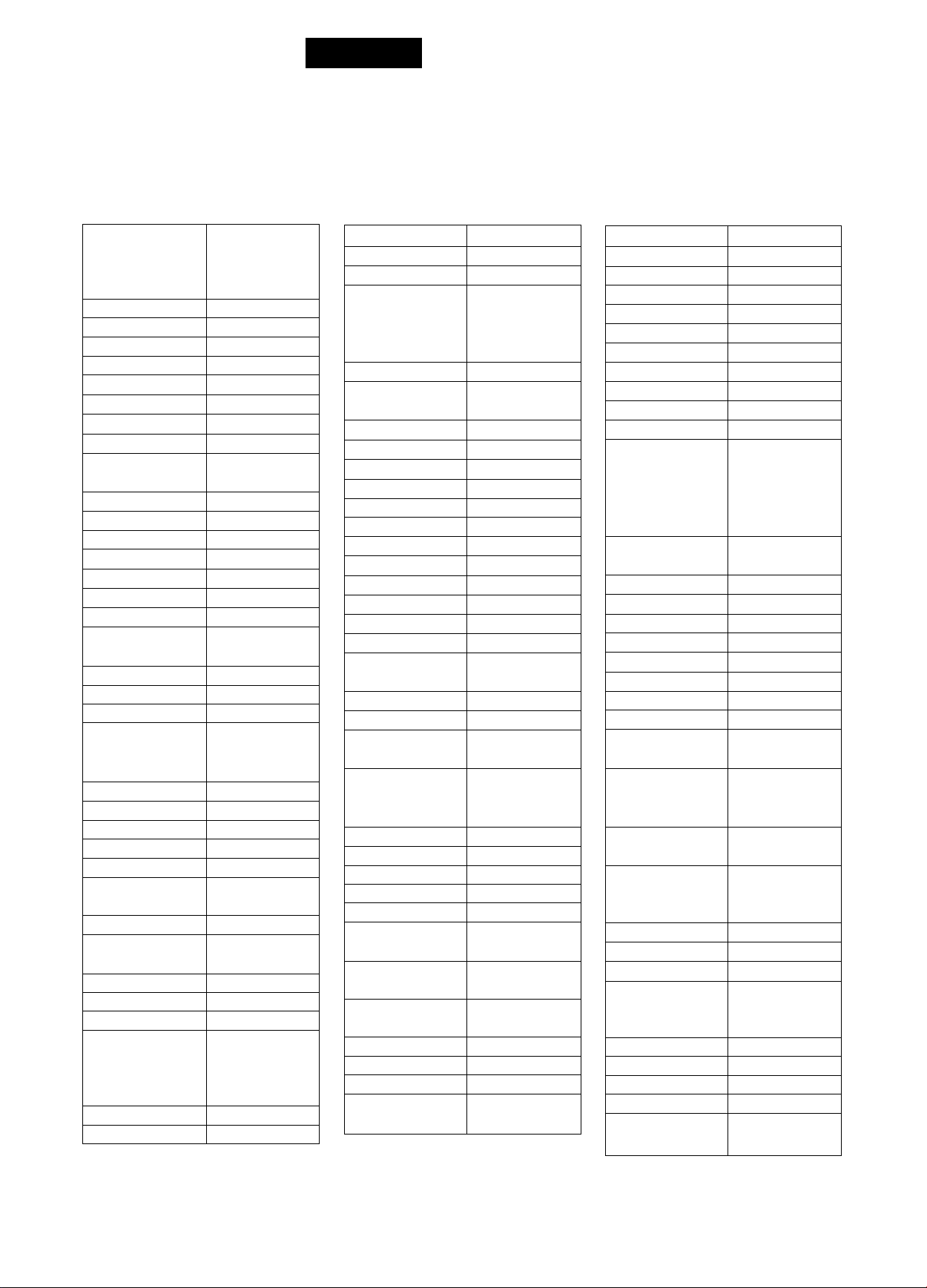
E/ANNEXE
ID CODES FOR TV
CÓDIGOS DE INDENTIFICACIÓN PARA TELEVISION
CODES 10 DE TELEVISEURS
•Ъ. >
BRAND NAME
MARCA
NOM DE MARQUE
A-Mark
Adventura 046
Aiko
Akai
Aileron
Ambassador
Anam
Anam National
AOC 003, 019, 030,
Archer
Audiovox
Beloor
Bell & Howell
Bradford
Brockwood
Broksonic
Candle
Carnivaie 030
Carver
Celebrity 000
Citizen
Ciairtone
Concerto .
Contee
Craig
Crown
Curtis Mathes
CXC
Daewoo
Daytron
Dumont
Eiectroband
Emerson
Envision
Fisher
ID CODE
CÓDIGO DE
IDENTIFICATION
CODE ID
003
092
030
179
177
180
055
137, 185
003
003, 180
019
016, 154
180
019
003
030, 046, 056,
186
054
030, 039, 046,
056, 060, 092,
186, 280
185
056
180, 185
180
039, 180
030, 039, 060,
154
180
019, 039, 092,
451
019
017, 019
000, 185
019, 039, 154,
177, 178, 179,
180, 185, 236,
280, 282, 463
030
154, 159
Fujitsu
Funai
Futu retech
GE 021, 027, 047,
Gibralter
GoidStar
Grunpy 179, 180
Hallmark
Harvard 180
Hitachi
Infinity 054
Janeil
JBL
JCB
JVC
KEC
Kenwood 019, 030
Kloss 024, 046
KTV
Logik
Luxman
LXI
Magnavox 020, 024, 030,
Majestic
Marantz
Matsushita
Megatron
MEI
Memorex
MGA
Midiand
Minutz
Mitsubishi
Motorola
MTC
179
171, 179, 180
180
051, 055, 135,
174, 178, 282,
451
017, 019, 030
019, 030, 039,
056, 178
178
056, 145, 151
046
054
000
053
180
030, 039, 180,
185, 280
016
056
047, 054, 154,
156,178
054, 096, 186,
187
016
030, 054
250
003, 145, 178
185
016, 056, 150,
154, 178
019, 030, 150,
178
017, 039, 047,
051, 135
021
019, 150, 178
055, 093
019, 030, 056,
060, 185
Multitech
NAD
NEC
Nikko
Noshi
NTC 092
Onwa
Optimus
Optonica 165
Orion
Panasonic 051,055, 250
Penney
Philco
Philips 054
Pilot
Pioneer
Portiand
Prism
ProScan
Proton
Puisar
Quasar
Radio Shack
RCA
Realistic
Rhapsody
Runco
Sampo
Samsung
Samsux
Sanyo
Scimitau
Scotch
Scott
180
156, 166, 178
019, 030, 056
030, 092, 178
018
180
154, 166, 250
236
003, 018, 019,
021,027, 030,
039, 047, 051,
060,135, 156,
178
019, 020, 030,
054, 096
019, 030, 039
166
019, 039, 092
051
047
003, 178, 466
017, 019
051,055, 165,
250
019, 030, 039,
047, 056, 154,
165, 178,180
018, 019, 047,
090, 135, 174
019, 030, 039,
056, 154, 165,
178, 180
185
017, 030, 494
030, 039
019, 030, 039,
056, 060, 178,
427
039
146, 154, 159
019
178
019, 178, 179,
180, 236
A-1
APPENDIX/APENDICE/ANNEXE
Page 63
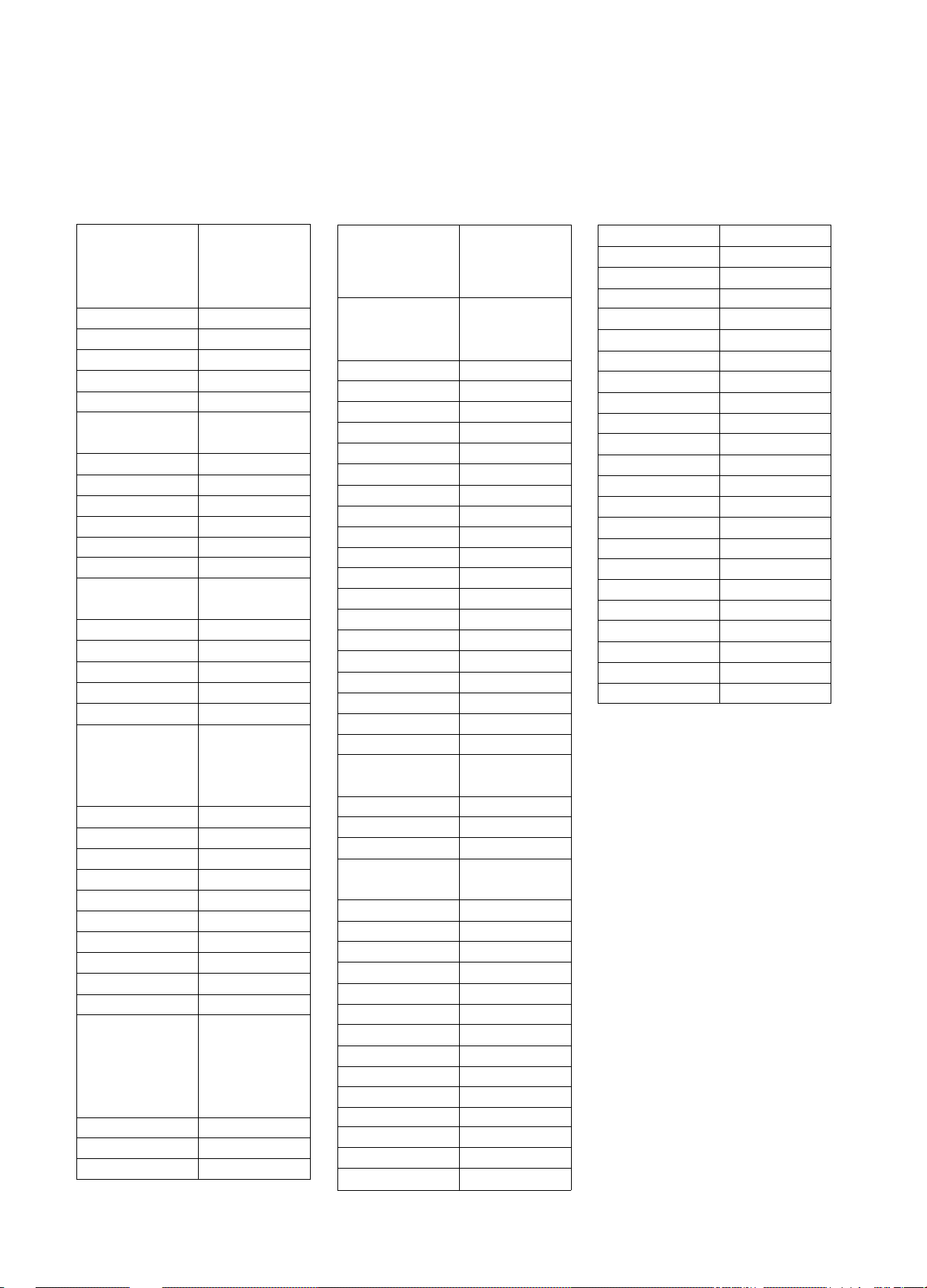
ID CODES FOR CABLE TV
Sears 047, 054, 056,
146, 154, 156,
159, 171, 178,
179
Sharp 039, 165
Shogun 019
Signature 016
Simpson
Sony
Soundesign
Spectricon 003, 137
Squareview 171
SSS
Starlite
Supre-Macy
Supreme 000
Sylvania
Symphonic 171
Tatung 003, 055
Technics 051,250
Technol Ace 179
Techwood 003, 051,056
Teknika 016, 019, 039,
TMK
Toshiba 060, 154, 156
Tosonic
Totevision 039
Universal 027
Vector Research 030
Victor 053
Vidikron
Vidtech
Viking
Wards 016, 019, 020,
Yamaha 019, 030
Zenith 016, 017
Zonda 003
186, 187
000, 080
178, 179, 180,
186
019, 180
180
046
020, 030, 054,
096
054, 056, 060,
092, 150, 179,
180,186
056, 177, 178
185
054
019, 178
046
021,027, 030,
054, 056, 080,
096, 165, 174,
176, 179
CÓDIGOS DE INDENTIFICACIÓN PARA CABLEVISIÓN
CODES 10 DE DECODEURS
BRAND NAME
MARCA
NOM DE MARQUE
ABC 001,003, 007,
Antronix
Archer 022, 153
Beloor 056
Cable Star 056
Cabletenna 022
Cableview
Century 153
Citizen 153, 315
Colour Voice 025
Comtronics 040
Contec
Eastern 002
Everquest 015, 040
Focus
Garrard 153
GC Electronics 056
Gemini 015
General Instrument
GoldStar 040, 144
Hamlin
Hitachi oil
Hytex
Jasco
Jerrold
Movie Time
Novaplex 618
NSC
Oak
Panasonic
Philips
Pioneer 144
Popular Mechanics
RCA
Recoton 400
Regal
Regency
Rembrandt oil
Samsung
ID CODE
CÓDIGO DE
IDENTIFICATION
CODE ID
008, oil, 013,
014, 017
022
022
019
400
oil, 476
009, 020, 034,
259
007
153, 315
003, oil, 012,
014, 015, 476
063, 156
063, 156
007, 019
021,107
025, 153
400
021
020, 259
002
040, 144
Scientific Atlanta 008, 017, 477
Signal
Signature
SL Marx
Sprucer 021
Starcom 003, 015
Stargate 015, 040
Starquest 015
Sylvanis 001
Tandy
Teleview
Texscan 001
Tocorn 012, 013
Tusa 015
TV86 063
Unika 022, 153
United Artists
United Cable
Universal
Vi dec way
Viewstar
Zenith
Zentek 400
015, 040
oil
040
258
040
007
003
022, 056, 153
250
063, 258
525
¡il
O
ÍÍ5
:z
•Ш Ш
13. X
< Ш
P
Ш
a.
a
<
APPENDIX/APENDICE/ANNEXE A-2
Page 64
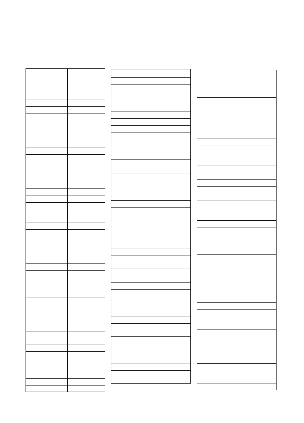
ID CODES FOR VCR
CÓDIGOS DE IDENTIFICACIÓN PARA VIDEOGRABADORAS
CODES ID DE MAGNETOSCOPES
BRAND NAME
MARCA
NOM DE MARQUE
Action
Adventura
Aiko
Aiwa
Akai
American High
Asha
Audiovox
Beaumark
Bell & Howell
Broksonic
Calix
Canon
Capehart
Carver
CCE
Citizen
Colt
Craig
Curtis Mathes
Cybernex
Daewoo
Daytzon
Dynatech
Electrohome
Electrophonic
Emerex
Emerson
Fisher
Fuji
Funai
Garrard
GE
Go Video
GoldStar
Gradiente
ID CODE
CÓDIGO DE
IDENTIFICATION
CODE ID
317
000
278
000, 037, 038,
307, 406, 468
041,061,315
035
240
037
240
104
121, 184, 211,
295, 361
037
035
020
081
072, 278
037, 278
072
037, 047, 072,
240, 271
035, 041, 060
240
020, 045, 278
020
000
037
037
032
000, 002, 037,
043, 061, 121,
184, 208, 211,
278,295, 361,
479
047, 054, 066,
104
033, 035
000
000
035, 060, 202
232, 350
037, 038
ООО
Harley Davidson
Harman/Kardon
Harwood
Headquarter
Hl-Q
Hitachi
Jensen
JVC
KEC
Kenwood
KLH
Kodak
Lloyd
Lloyd’s
Logik
LXI
Magnavox
Magnin
Marantz
Marta
Matsushita
MEI
Memorex
MGA
MGN Technology
Minolta
Mitsubishi
Motorola
MTC
Multitech
NEC
Nikko
Nikon
Noblex
Olympus
Optimus
Optonica
Orion
Panasonic
000
038
072
046
047
041,042
041
008, 041, 067
037, 278
038, 041,067
072
035, 037
000
208
072
037
035, 039, 081,
110, 149
240
035, 081
037
035, 162, 454
035
000, 035, 037,
039, 046, 047,
104, 240, 307
043, 061
240
042
043, 061, 067,
173
035
000, 240
000, 072
038, 041, 067,
104
037
034
240
035
037, 037, 104,
162, 454
062
295, 479
035, 162, 225,
454
Penney
Pentax
Philco
Philips
Pilot
Pioneer
Portland
Protec
Pulsar
Quarter
Quartz
Quasar
Radio Shack
Radix
Randex
RCA
Realistic
Ricoh
Runco
Samsung
Sanky
Sansui
Sanyo
Scott
Sears
Sharp
Shintom
Shogun
Singer
Sony
STS
Sylvania
Symphonic
Tatung
Teac
Technics
035, 037, 038,
042, 054, 240
042
035
035, 062, 081,
110
037
067
020
072
039
046
046
035, 162, 454
000, 037
037
037
042, 060, 149,
202
000, 035, 037,
046, 047, 062,
066, 104, 240
034
039
045, 240
039
041,067, 271
046, 047, 104,
240
043, 045, 121,
184, 211
035, 037, 042,
046, 047, 054,
066, 104,
062
072
240
072
032, 033, 034,
035
042
000, 035, 043,
081, 110
000
041
Э00, 041
035, 162
A-3
APPENDIX/APENDICE/ANNEXE
Page 65
ID CODES FOR CD PLAYER
Teknika
TMK
Toshiba 043, 045, 060,
Totevision
Unitech 240
Vector
Vector 038
Research
Video Concepts 045, 061
Videosonic 240
Wards 000, 035, 042,
XR-1000 000, 035, 072
Yamaha 038
Zenith
000, 035, 037
208, 240
066
037, 240
045
047, 060, 062,
072, 149, 240
033, 034, 039
CÓDIGOS DE IDENTIFICACÓN PARA REPRODUCTORES DE DISCOS COMPACTOS
CODES ID DE LECTEURS CD
BRAND NAME
MARCA
NOM DE MARQUE CODE ID
Aiwa 124, 157
California Audio Lab
Carver
Denon
DKK 000
Emerson
Fisher
Garrard
Genexxa 032, 305
Hitachi
JVC 072
Kenwood
Krell
LVI
Magnavox
Marantz
MCS 029
Mission 157
NSM 157
Onkyo 101
Optimus 000, 032, 179,
Panasonic 029
Philips 157
Pioneer
Proton 157
QED 157
Quasar
RCA
Reaiistic 179
Rotel
SAE 157
Sansui 157, 305
Sanyo 179
Scott 305
Sears 305
Sony
Soundesign 145
Teac
Technics 029, 303
Victor 072
Yamaha 036, 187
ID CODE
CÓDIGO DE
IDENTIFICATION
029
157, 179
003
305
048, 088, 179
393
032
028, 048, 190
157
305
157
029, 157
305, 468
032, 305, 468
029
053, 179, 305
157
000, 185, 490,
604, 605
393
Q
O
Q
:¡:
-UJ Ш
D. X
< Ш
p
LJ
CL
D.
<
APPENDIX/APÉNOiCE/ANNEXE A~A-
Page 66

Page 67

Page 68

AIWA CO.,LTD.
For assistance and information call toll free 1-800-BUY-AIWA (United States and Puerto Rico)
Printed in Malaysia
 Loading...