

8Z-AR4-903-01
9901 15Ac~-y43
ml
ml
T
For assistance and information
call toll free I-800-BUY-AIWA
(United States and Puerto Rico)
/ 7 \ IR’SKER%Y”CKI/’ ! \
“CAUTION:TO REDUCE THE RISK OF
ELECTRIC SHOCK,
DO NOT REMOVE COVER (OR BACK).
NO USER-SERVICEABLE PARTS INSIDE.
REFER SERVICING TO QUALIFIED
SERVICE PERSONNEL.”
Owner’s record
For your convenience, record the model number and serial
number (you will find them on the rear of your unit) in the space
provided below. Please refer to them when you contact your
Aiwa dealer in case of difficulty.
Model No.
Serial No. (Lot No.)
AV-D35
PRECAUTIONS
Read the Operating Instructions carefully and completely before
operating the unit. Be sure to keep the Operating Instructions
for future reference. All warnings and cautions in the Operating
Instructions and on the unit should be strictly followed, as well
as the safety suggestions below.
Installation
1
2
3
4
5
6
7
Water and moisture — Do not use this unit near water, such
as near a bathtub, washbowl, swimming pool, or the like.
Heat — Do not use this unit near heat sources, including
heating vents, stoves, or other appliances that generate heat.
It also should not be placed in temperatures less than 5°C
(41“F) or higher than 35°C (95”F).
Mounting surface — Place the unit on a flat, even surface.
Ventilation — The unit should be situated with adequate
space around it so that proper heat ventilation is assured.
Allow 10 cm (4 in.) clearance from the rear and the top of the
unit, and 5 cm (2 in.) from each side.
- Do not place the unit on a bed, rug, or similar surface that
may block the ventilation openings.
- Do not install the unit in a bookcase, cabinet, or airtight
rack where ventilation may be impeded.
Objects and liquid entry — Take care that objects or liquids
do not get inside the unit through the ventilation openings.
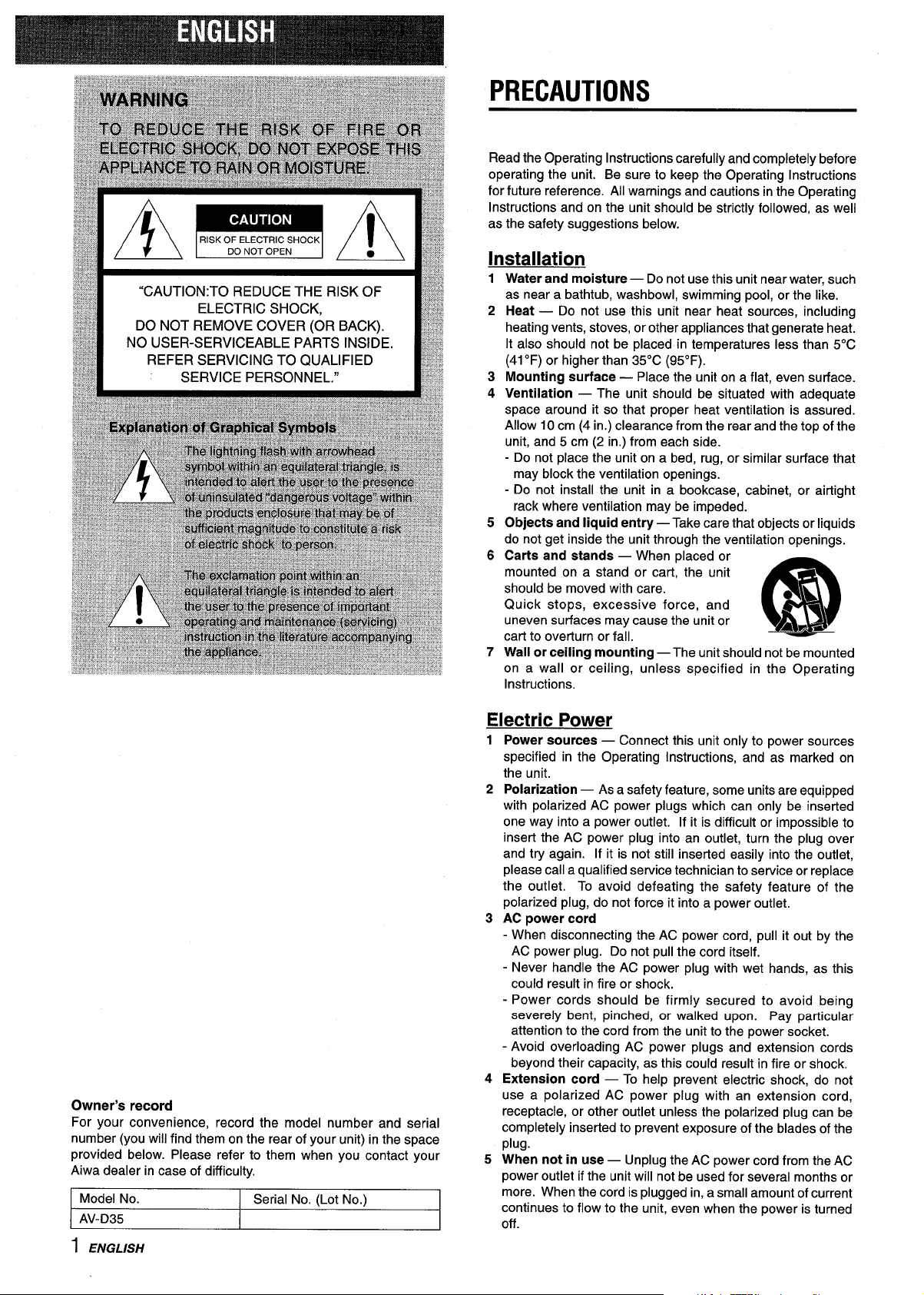
Carts and stands — When placed or
mounted on a stand or cart, the unit
should be moved with care.
Quick stops, excessive force, and
uneven surfaces may cause the unit or
m
3
A&~
cart to overturn or fall.
Wall or ceiling mounting — The unit should not be mounted
on a wall or ceiling, unless specified in the Operating
Instructions.
Electric Power
1
2
3
4
5
Power sources — Connect this unit only to power sources
specified in the Operating Instructions, and as marked on
the unit.
Polarization — As a safety feature, some units are equipped
with polarized AC power plugs which can only be inserted
one way into a power outlet. If it is difficult or impossible to
insert the AC power plug into an outlet, turn the plug over
and try again. If it is not still inserted easily into the outlet,
please call a qualified service technician to service or replace
the outlet. To avoid defeating the safety feature of the
polarized plug, do not force it into a power outlet.
AC power cord
- When disconnecting the AC power cord, pull it out by the
AC power plug. Do not pull the cord itself.
- Never handle the AC power plug with wet hands, as this
could result in fire or shock.
- Power cords should be firmly secured to avoid being
severely bent, pinched, or walked upon. Pay particular
attention to the cord from the unit to the power socket.
- Avoid overloading AC power plugs and extension cords
beyond their capacity, as this could result in fire or shock.
Extension cord — To help prevent electric shock, do not
use a polarized AC power plug with an extension cord,
receptacle, or other outlet unless the polarized plug can be
completely inserted to prevent exposure of the blades of the
plug.
When not in use — Unplug the AC power cord from the AC
power outlet if the unit will not be used for several months or
more. When the cord is plugged in, a small amount of current
continues to flow to the unit, even when the power is turned
off.
1 ENGLISH
Outdoor Antenna
1 Power lines — When connecting an outdoor antenna, make
sure it is located away from power lines.
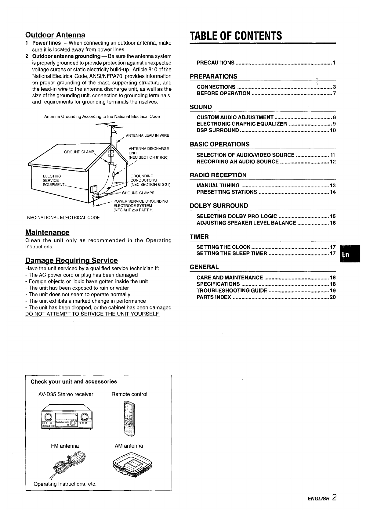
2 Outdoor antenna grounding — Be sure the antenna system
is properly grounded to provide protection against unexpected
voltage surges or static electricity build-up. Article 810 of the
National Electrical Code, ANS1/NFPA70, provides information
on proper grounding of the mast, supporting structure, and
the lead-in wire to the antenna discharge unit, as well as the
size of the grounding unit, connection to grounding terminals,
and requirements for grounding terminals themselves.
AntennaGroundingAccordingtothe NationalElectricalCode
)
(NEC ART 250 PART H)
NEC-NATIONALELECTRICALCODE
Maintenance
Clean the unit only as recommended in the Operating
Instructions.
Darnaqe Requirinq Service
Have the unit serviced by a qualified service technician if:
- The AC power cord or plug has been damaged
- Foreign objects or liquid have gotten inside the unit
- The unit has been exposed to rain or water
- The unit does not seem to operate normally
- The unit exhibits a marked change in performance
- The unit has been dropped, or the cabinet has been damaged
DO NOT ATTEMPT TO SERVICE THE UNIT YOURSELF.
Check your unit and accessories
AV-D35 Stereo receiver
Remote control
FM antenna
AM antenna
Operating Instructions, etc.
TABLE OF CONTENTS
PRECAUTIONS ...................................................................
1
PREPARATIONS
CONNECTIONS
++;
...................................................................
BEFORE OPERATION .........................................................i'
SOUND
CUSTOM AUDI() ADJUSTMENT ....................... .............. 8
ELECTRONIC GRAPHIC EQUALIZER ............................ $)
DSP SURROUNID ............................................................. 10
BASIC OPERATIONS
—— .
SELECTION OF AUDIO/VIDEO SOURCE ...................... Ill
RECORDING AINAUDIO SOURCE .................................. 12!
RADIO RECEPTION
——-
MANUALTUNING ............................................................. 13
PRESETTING STATIONS ................................................. 14
DOLBY SURROUND
SELECTING DC)LBY PRO LOGIC ................................... 15
ADJUSTING SPEAKER LEVEL BALANCE ...................... 16
TIMER
SETTING THE CLOCK ................>..................................... 17
SETTING THE SLEEP TIMER .......................................... 17
m
GENERAL
CARE AND MAINTENANCE ............................................. 1[3
SPECIFICATIONS .............................................................1[3
TROUBLESHOOTING GUIDE ..........................................1!3
PARTS INDEX .....................................m.............................2{)
ENGLISH 2
CONNECTIONS
CONNECTING EQUIPMENT
Jacks and plugs of the connecting cord are color-coded as
follows:
Before connecting the AC cord
Red jacks and plugs : For the right channel of audio signals
The rated voltage of your unit shown on the rear panel is 120 V
White jacks and plugs: For the left channel of audio signals
AC. Check that the rated voltage matches your local voltage.
Yellow jacks and plugs: For video signals.
IMPORTANT
m
Connect the speakers, antennas, and all other external
Insert the plugs fully into the jacks. Loose connections may
equipment first. Then connect the AC cord at the end.
produce a humming sound or other noise interference.
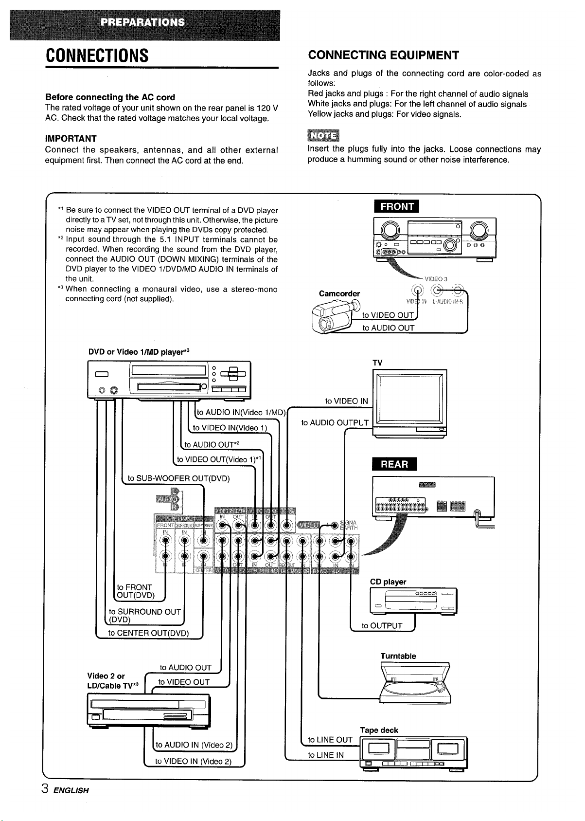
“ Be sure to connect the VIDEO OUT terminal of a DVD player
directly to a TV set, not through this unit.Otherwise,the picture
noise may appear when playing the DVDScopy protected.
F
o
0
‘2 Input sound through the 5.1 INPUT terminals cannot be
o
@
Onnan o ~ ~ ~
recorded. When recording the sound from the DVD player,
Do 0
@@Zm30 “
connect the AUDIO OUT (DOWN MIXING) terminals of the
DVD player to the VIDEO l/DVD/MD AUDIO IN terminals of
the unit.
vlrxo
3
*3When connecting a monaural video, use a stereo-mono
, ...\ ..,$
~,,.’ ,,”’.,,
Camcorder
connecting cord (not supplied).
\ ... ‘..../ ‘y;
!,/IL)E] N L-#,JD10ii.<
I I I [ to SUB-WOOFER OUT(DVD)
11111
II
to SURROUNDOUT
[n\ln\
I 1111
II I
I
“~m
I
r
!- v u)
J
‘1111 Ill
L
to OUTPUT
to CENTER OUT(DVD)
J
1111
Ill
Turntable
iDK2ableTV*3_l I
Vldao 2 or
II
L_
Tape deck
to LINE OUT
to LINE IN
lu]~lul
a
~~
-
3 ENGLISH
@)Surround speakers
—
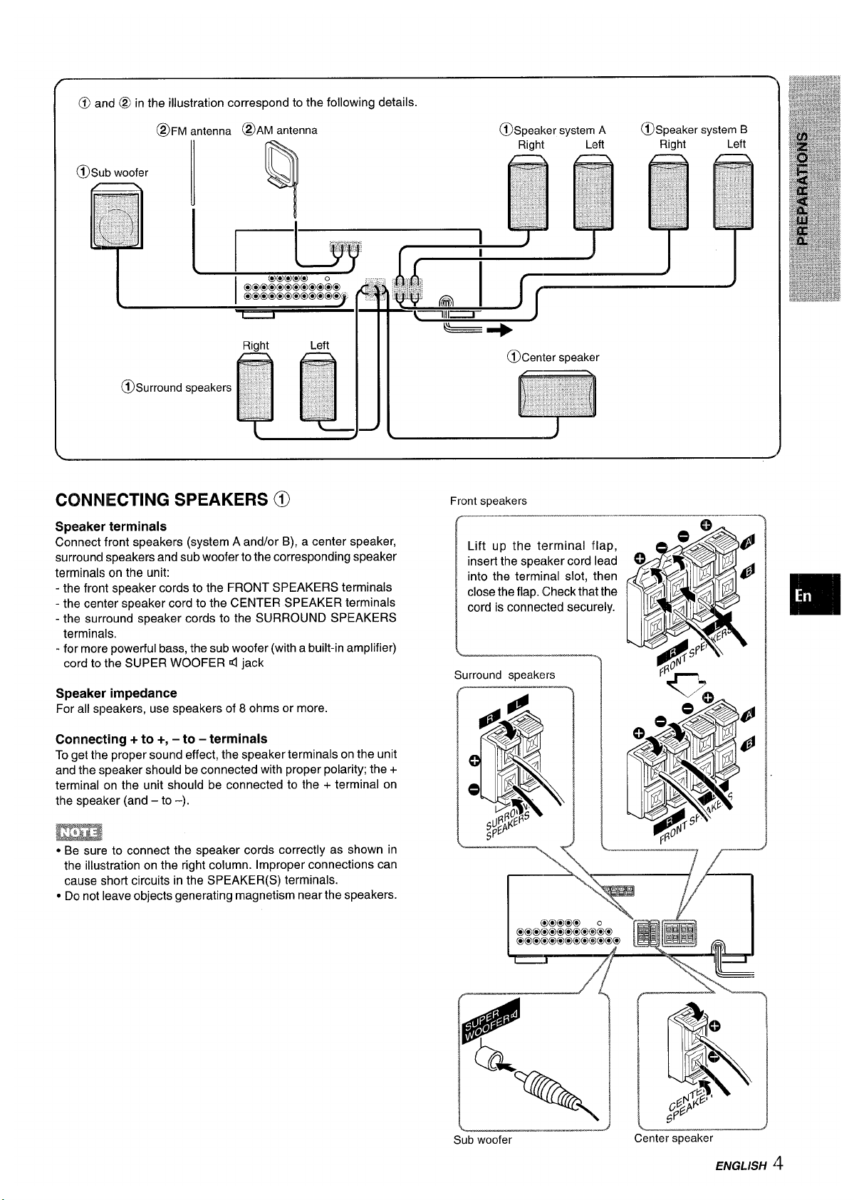
CONNECTING SPEAKERS @
Front speakers
Speaker terminals
Connect front speakers (system A and/or B), a center speaker,
surround speakers and sub woofer to the corresponding speaker
terminals on the unit:
- the front speaker cords to the FRONT SPEAKERS terminals
- the center speaker cord to the CENTER SPEAKER terminals
- the surround speaker cords to the SURROUND SPEAKERS
terminals.
- for more powerful bass, the sub woofer (with a built-in amplifier)
cord to the SUPER WOOFER d iack
Lift up the terminal flap,
insert the speaker cord lead
into the terminal slot, then
close the flap. (Checkthat the
cord is connected securely.
Surround speakers
Speaker impedance
For all speakers, use speakers of 8 ohms or more.
Connecting + to +, – to – terminals
To get the proper sound effect, the speaker terminals on the unit
and the speaker should be connected with proper polarity; the +
terminal on the unit should be connected to the + terminal on
the speaker (and – to -).
EEiza
● Be sure to connect the speaker cords correctly as shown in
the illustration on the right column. Improper connections can
cause short circuits in the SPEAKER(S) terminals.
● Do not leave objects generating magnetism near the speakers.
—
7 r“
~.
Sub woofer
.
~.
Center speaker
ENGLISH ‘$
POSITIONING THE SPEAKERS
Position the speakers to make the most of the Dolby Digital
Surround (5.1 CH), Dolby Pro Logic or DSP effect.
@ Front speakers
@ Center speaker
Position in the center of the two front speakers. In addition,
position on or below the TV set, if connecting a TV set to the
unit.
@ Surround speakers
Place the surround speakers directly to the side of or slightly
behind the listening area. Align them horizontally, about 1
meter (3.2 feet) above ear height.
@ Sub woofer
Place the sub woofer in any place between the two front
speakers.
Sound from the surround speakers or center speaker depends
on the setting of the DSP, Dolby Pro Logic and 5.1 CH function.
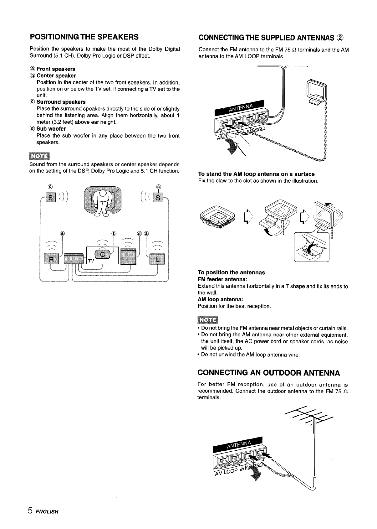
CONNECTING THE SUPPLIED ANTENNAS @
Connect the FM antenna to the FM 75 Q terminals and the AM
antenna to the AM LOOP terminals,
-=+4
To stand the AM loop antenna on a surface
Fix the claw to the slot as shown in the illustration.
To position the antennas
FM feeder antenna:
Extend this antenna horizontally in a T shape and fix its ends to
the wall.
AM loop antenna:
Position for the best reception.
● Do not bring the FM antenna near metal objects or curtain rails.
● Do not bring the AM antenna near other external equipment,
the unit itself, the AC power cord or speaker cords, as noise
will be picked up.
● Do not unwind the AM loop antenna wire.
CONNECTING AN OUTDOOR ANTENNA
For better FM reception, use of an outdoor antenna is
recommended. Connect the outdoor antenna to the FM 75 Cl
terminals.
5 ENGLISH
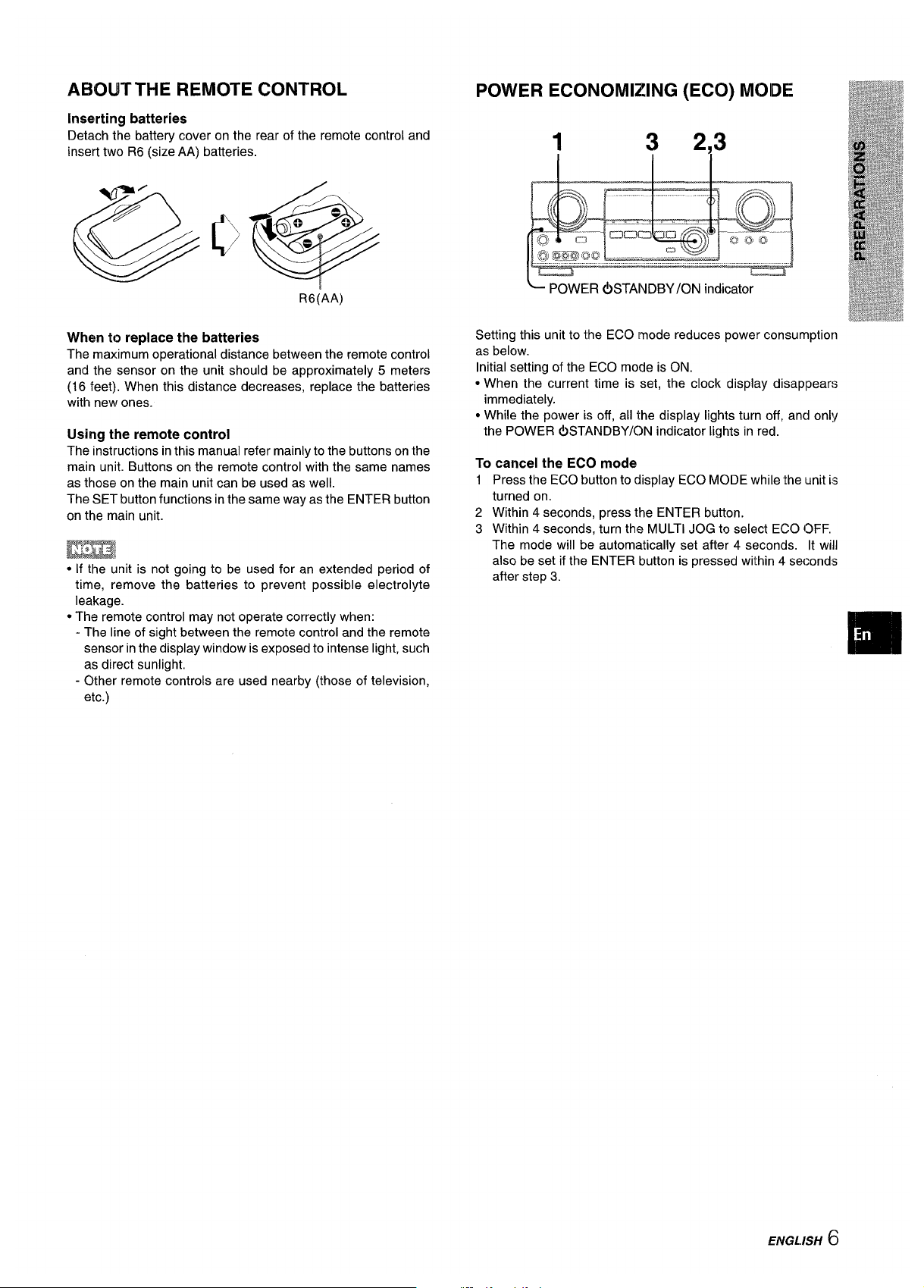
ABOIJTTHEREMOTE CONTROL
inserting batteries
Detach the battery cover on the rear of the remote control and
insert two R6 (size AA) batteries.
R6(AA)
When to replace the batteries
The maximum operational distance between the remote control
and the sensor on the unit should be approximately 5 meters
(16 feet). When this distance decreases, replace the batteries
with new ones.
Using the remote control
The instructions in this manual refer mainly to the buttons on the
main unit. Buttons on the remote control with the same names
as those on the main unit can be used as well.
The SET button functions in the same way as the ENTER button
on the main unit.
● If the unit is not going to be used for an extended period of
time, remove the batteries to prevent possible electrolyte
leakage.
● The remote control may not operate correctly when:
- The line of sight between the remote control and the remote
sensor in the display window is exposed to intense light, such
as direct sunlight.
- Other remote controls are used nearby (those of television,
etc.)
POWER ECONOMIZING (ECO) MOIDE
1
3 2.3
l—
LJ
L POWER &3TANDBY/ON indicator
Setting this unit to the ECO mode reduces power consumption
as below.
Initial setting of the ECO mode is ON.
● When the current time is set, the clock display disaploears
immediately.
● While the power is off, all the display lights turn off, anc~only
the POWER &3TANDBY/ON indicator lights in red.
To cancel the ECO mode
1
2
3
Press the ECO button to display ECO MODE while the unit is
turned on.
Within 4 seconds, press the ENTER button.
Within 4 seconds, turn the MULTI JOG to select ECO OFF,
The mode will be automatically set after 4 seconds. It will
also be set if the ENTER button is pressed within 4 seconds
after step 3.
ENGL.ISH 6
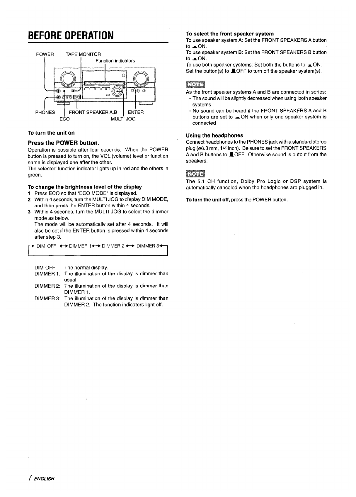
BEFORE OPERATION
POWER TAPE MONITOR
I
I
Function indicators
PHONES I FRONT SPEAKERA,B I ENTER
ECO
MULTI JOG
To turn the unit on
Press the POWER button.
Operation is possible after four seconds. When the POWER
button is pressed to turn on, the VOL (volume) level or function
name is displayed one after the other.
The selected function indicator lights up in red and the others in
green.
To change the brightness level of the display
1
2
3
Press ECO so that “ECO MODE” is displayed.
Within 4 seconds, turn the MULTI JOG to display DIM MODE,
and then press the ENTER button within 4 seconds.
Within 4 seconds. turn the MULTI JOG to select the dimmer
mode as below.
The mode will be automatically set after 4 seconds. It will
also be set if the ENTER button is pressed within 4 seconds
after step 3.
DIM OFF *DIMMER 1- DIMMER 2- DIMMER3
DIM-OFF:
DIMMER1:
DIMMER 2:
DIMMER 3:
The normal display.
The illumination of the display is dimmer than
usual.
The illumination of the display is dimmer than
DIMMER 1.
The illumination of the display is dimmer than
DIMMER 2. The function indicators light off.
To select the front speaker system
To use speaker system A: Set the FRONT SPEAKERS A button
to wON.
To use speaker system B: Set the FRONT SPEAKERS B button
to wON.
To use both speaker systems: Set both the buttons to s ON.
Set the button(s) to IOFF to turn off the speaker system(s).
As the front speaker systems A and B are connected in series:
- The sound will be slightly decreased when using both speaker
systems
- No sound can be heard if the FRONT SPEAKERS A and B
buttons are set to *ON when only one speaker system is
connected
Using the headphones
Connect headphones to the PHONES jack with a standard stereo
plug (06.3 mm, 1/4 inch). Be sure to set the FRONT SPEAKERS
A and B buttons to l.OFF. Otherwise sound is output from the
speakers.
m
The 5.1 CH function, Dolby Pro Logic or DSP system is
automatically canceled when the headphones are plugged in.
To turn the unit off, press the POWER button.
7 ENGLISH
CUSTOM AUDIO ADJUSTMENT
VOL
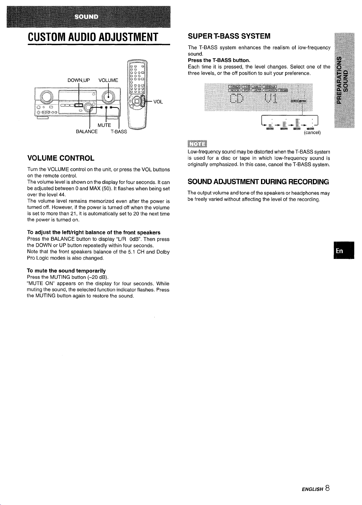
VOWME CONTROL
Turn the VOLUME control on the unit, or press the VOL buttons
on the remote control.
The volume level is shown on the display for four seconds. Itcan
be adjusted between Oand MAX (50). It flashes when being set
over the level 44.
The volume level remains memorized even after the power is
turned off. However, if the power is turned off when the volume
is set to more than 21, it is automatically set to 20 the next time
the power is turned on.
To adjust the Ieft/right balance of the front speakers
Press the BALANCE button to display “L/R OdB. Then press
the DOWN or UP button repeatedly within four seconds.
Note that the front speakers balance of the 5.1 CH and Dolby
Pro Logic modes is also changed,
(cancel)
m
Low-frequency sound may be distorted when the T-BASS system
is used for a disc or tape in which low-frequency sound is
originally emphasized. In this case, cancel the T-BASS system.
SOUND ADJUSTMENT DURING RECORDING
The output volume and tone of the speakers or headphones may
be freely varied without affecting the level of the recording.
To mute the sound temporarily
Press the MUTING button (–20 dB).
‘(MUTE ON” appears on the display for four seconds. While
muting the sound, the selected function indicator flashes. Press
the MUTING button again to restore the sound.
ENGL.ISH 8
ELECTRONIC GRAPHIC
E(IUALIZER
GEQ
This unit provides the following five different equalization modes.
ROCK: Powerful sound emphasizing treble and bass
POP: More presence in the vocals and midrange
JAZZ: Accented lower frequencies for jazz-type music
CLASSIC: Enriched sound with heavy bass and fine treble
BGM: Calm tone with suppressed bass and treble
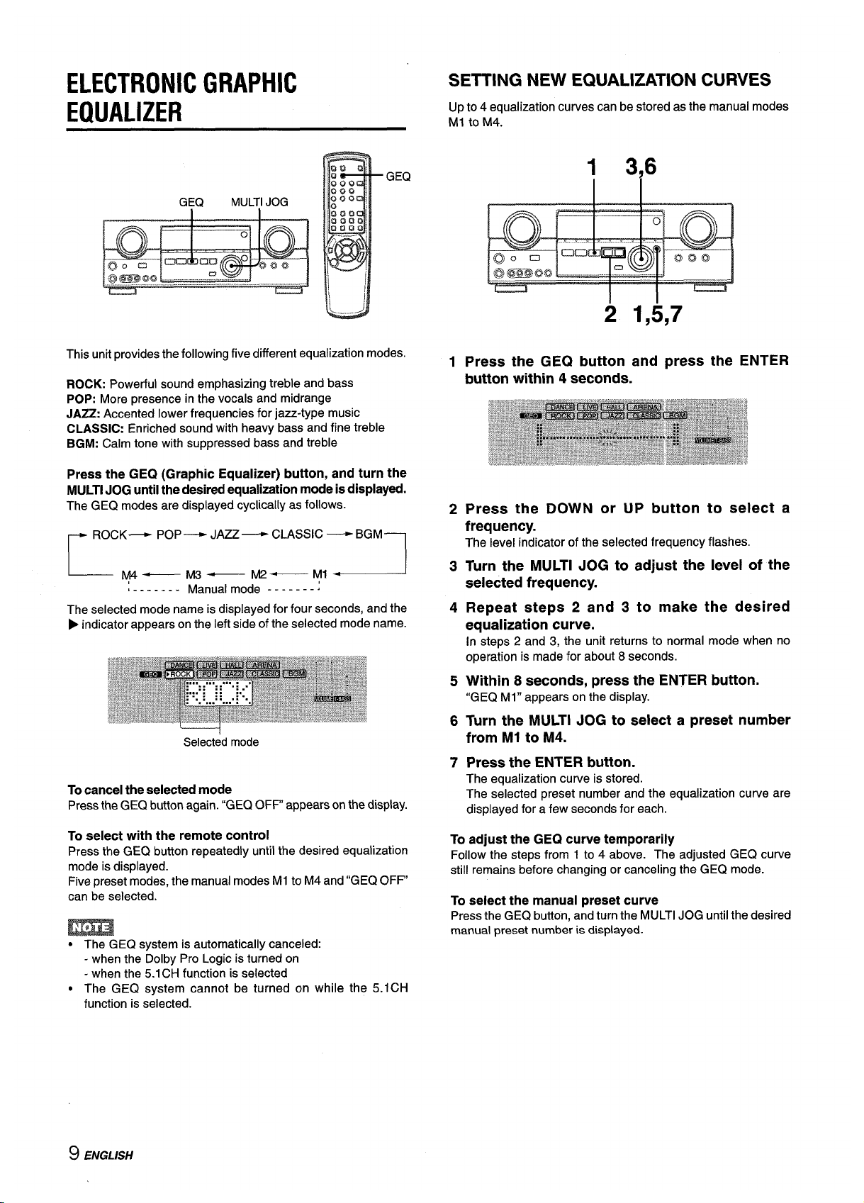
Press the GEQ (Graphic Equalizer) button, and turn the
MULTI JOG until the desired equalization mode is displayed.
The GEQ modes are displayed cyclically as follows.
r
ROCK— PoP—
JAZZ —
CLASSIC
—
BGM
1
L-..._M4
—M3— M2—
Ml ~
L------- Manual mode -------;
The selected mode name is displayed for four seconds, and the
➤ indicator appears on the left side of the selected mode name.
Selected mode
To cancel the selected mode
Press the GEQ button again. “GEQ OFF” appears on the display.
To select with the remote control
Press the GEQ button repeatedly until the desired equalization
mode is displayed.
Five preset modes, the manual modes Ml to M4 and “GEQ OFF
can be selected.
SETTING NEW EQUALIZATION CURVES
Up to 4 equalization curves can be stored as the manual modes
Ml to M4.
1
2
3
4
5
6
7
1 3,6
2 1,5,7
Press the GEQ button and press the ENTER
button within 4 seconds.
Press the DOWN or UP button to select a
frequency.
The level indicator of the selected frequency flashes.
Turn the MULTI JOG to adjust the level of the
selected frequency.
Repeat steps 2 and 3 to make the desired
equalization curve.
In steps 2 and 3, the unit returns to normal mode when no
operation is made for about 8 seconds.
Within 8 seconds, press the ENTER button.
“GEQ Ml” appears on the display.
Turn the MULTI JOG to select a preset number
from Ml to M4.
Press the ENTER button.
The equalization curve is stored.
The selected preset number and the equalization curve are
displayed for a few seconds for each.
To adjust the GEQ curve temporarily
Follow the steps from 1 to 4 above. The adjusted GEQ curve
still remains before changing or canceling the GEQ mode.
To select the manual preset curve
Press the GEQ button, and turn the MULTI JOG until the desired
manual preset number is displayed.
● The GEQ system is automatically canceled:
- when the Dolby Pro Logic is turned on
- when the 5.1CH function is selected
● The GEQ system cannot be turned on while the 5.ICH
function is selected.
9 ENGLISH

DSPSURROUND
DSP MULTIJOG
DOW”N,UP
DSP
MANUAL
SELECT
The DSP (Digital Signal Processor) surround circuits can recreate
the effect of sounds reflected from walls or ceilings, to obtain the
sound presence of real environments. There are four modes with
matching graphic equalization modes. Equalization modes are
selected automatically and can also be selected or turned off to
suit your preference.
Press the DSP button, and turn the MULTI JOG until
the desired DSP mode is displayed.
The selected mode name is displayed for four seconds, and the
indicators P appears on the left sides of the selected DSP name
and matching GEQ mode name.
Selected pSP mode
Matching GEQ mode
To cancel the selected mode
Press the DSP button again. “DSP OFF” appears on the display.
Even if canceling the selected DSP mode, the matching or
selected GEQ mode still remains.
To select with the remote control
Press the DSP butiton repeatedly until the desired [)SP mode is
displayed.
Four DSP modes and “DSP OFF can be selected.
To adjust the volume and balance of the! surroumd
speakers
Press the MANUAI- SELEC-r button on the remote control twice
or three times, while the DSP system is turned on, lo display “S-
R OdB”(for right surround speaker) or “S-L OdB (for left surround
speaker). Then press the DOWN or UP button repeatedly within
four seconds.
Note that the surround speakers volume and balance of tlhe 5.1
CH and Dolby Pro Logic modes are also changed.
● The DSP system is automatically canceled:
- when the Dolby Pro Logic is turned on
- when the 5.1 CH function is selected
● The DSP system cannot be turned on:
- while the 5.1 Cl-l functiorl is selected
- while headphones are plugged in
When the music source is monaural
Select LIVE to obtain a simulated stereo effect. When DANCE,
HALL or ARENA is selected, no sound will be heard from the
surround speakers.
,ENGL/!5H II
O

SELECTION OF AUDIO/VIDEO
SOURCE
1
2
3
FUNCTION Function indicators
ENTER
DOWN~UP I
MULTI JOG
VIDEO 1/5.1CH/BAND
Select the program source.
Turn the FUNCTION selector or press the TAPE MONITOR
button. The selected function indicator flashes in red.
I Radio I TUNER
I
Record I PHONO
Compact disc I CD
I Television, etc. I AUX
I
Video
VIDEO l/DVD/MD,
VIDEO 2/LD/TV, VIDEO 3
LD or Cable TV VIDEO 2
1
MD or DVD VIDEO l/DVD/MD
To select a function on the remote control
Press the desired function button directly.
The function to be selected (except PHONO) depend on the
equipment connected to the input terminals on the rear panel
of the unit.
When using a turntable with a built-in equalizer amplifier, set
the switch of the equalizer amplifier to off. Seethe instructions
of the turntable for further information.
Start the selected program source.
Adjust the sound.
About the video source to the monitor orTV
Selected video source
VI: VIDEO1 ,V2: VIDE02, V3: VIDE03
To select the video source
1 Select one of the functions except TUNER.
2 Press the ENTER button to display VIDEO 1.
3 Turn the MULTI JOG to select VIDEO 2 or VIDEO 3.
To change a displayed name for the VIDEO
1 and VIDEO 2
When the VIDEO 1 is selected, VIDEO 1 is displayed initially. It
can be changed to DVD or MD.
Press the VIDEO l/5.1 CH/BAND button while pressing the
ENTER button.
To use the 5.1CH function, press the VIDEO 1/5.1CH/BAND
button. The function name will change to “5.1 ch IN” and the
source connected to the 5.1 INPUT terminals is selected.
To resume, press the button again so that the selected function
name is displayed.
The displayed name for VIDEO 2 button can be changed to
VIDEO 2, LD orT~ while the VIDEO 2 function isselected, press
the VIDEO 1/5.1CH/BAND button while pressing the ENTER
button.
To adjust the sound level of the connected
source
The input sensitivity level of each function (except the TUNER
function) can be adjusted.
When the sound level of the connected source is higher or lower
than that of the TUNER, adjust it as follows.
1 Select the function to be adjusted.
Turn the MULTI JOG accordingly and play the source,
2 Press the UP
or DOWN button repeatedly.
The level can be adjusted between -6dB (MIN) and +8dB (MAX)
in 2dB steps. Adjust the level so that the sound is output at the
same level as the TUNER.
● The input sensitivity level of the TUNER function cannot be
adjusted.
● That of the TAPE MONITOR cannot be adjusted either.
Even if the TAPE MONITOR is selected and the TAPE
MONITOR indicator turns red, pressing the UP or DOWN button
will change the level of the function displayed on the window.
The selected video source is indicated on the display and the
video signal through the MONITOR VIDEO OUT jack is output
on the TV.
:1 ENGLISH

TO PLAY A DVD RECORDED IN DOLBY
DIGITAL SURROUND
This receiver has the 5.1 INPUT connectors supporting Dolby
Digital decoder with the 5.1 ch output terminals. When a DVD
player that contains a Dolby Digital decoder is connected to the
receiver, you can enjoy theater-quality audio right in your home
when playing discs recorded in Dolby Digital Surround.
1 Turn the FUNCTION selector to select the VIDEO
l/DVD/MD function.
3 Start playing the DVD recorded
in Dolby Digital
Surround.
EEma
* The 5.1 CH function is automatically canceled and the VIDEO
1, DVD or MD function is selected:
- when the Dolby Pro Logic is turned on
- when headphones are plugged in
● The 5.1 CH function cannot be selected while headphones are
plugged in.
RECORDING AN AUDIO SOURCE
——.
1 ENTER
1
2
3
TAPEMC)NITOR
MULTIJOG
Select the program source to be recolrded.
Turn the FUNCTION selector.
Set the tape deck or MD recorder to the recording
mode.
Start the selected program source.
To monitor recorded sound during recording (when thle
connected tape deck is a three-head systemk)
Press the TAPE MONITOR button. “TAPE ON” appears on the
display for four seconds, and then the source name selected in
step 1comes back on. To cancel the tape monitor, press it again
so that “TAPE OFF” appears.
m
● Any sound control system has no effect on recording (see page
8).
c Input sound through the 5.1 INPUT terminals cannot be
recorded. When recording the sound from the DVD player,
connect the AUDIO OUT (DOWN MIXING) terminals of the DVD
player to the VIDEO l/DVD/MD AUDIO INterminids ofthe unit,
● When recording sources by the MD recorder ccmnecteclto the
VIDEO l/DVD/MD AUDIO OUT terminals, first press the
ENTER button tc)display VIDEO 1, and turn the MULTI ,JOGto
select VIDEO 2 or VIDEO 3. Then select the source (W or \/3
should be displayed).
Recording cannot be done while the V1 indication is displayed
on the window.
● Input sound from the tape deck connected to the TAF’E
MONITOR IN terminals cannot be recorded.
MANUAL TUNING
MONO
TUNER
1
2
L—”——i
I
L--Al
1
u
<......>
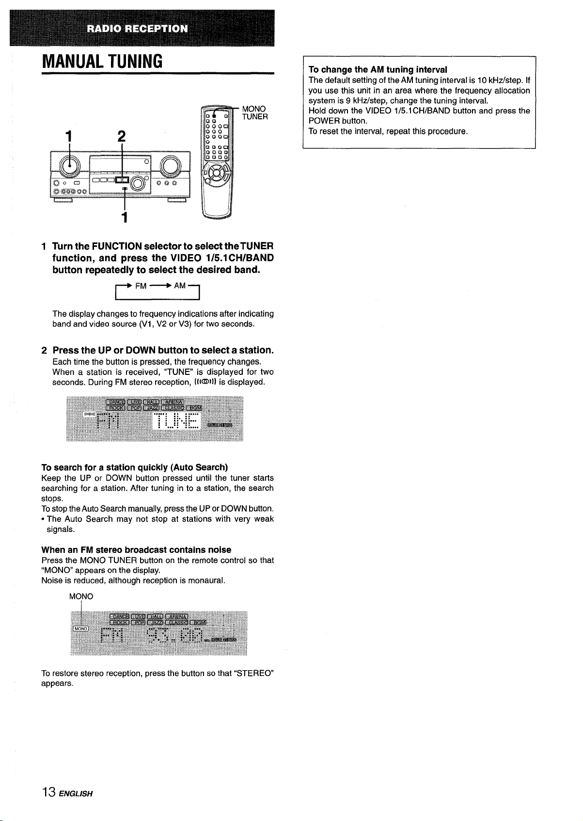
Turn the FUNCTION selector to select theTUNER
function, and press the VIDEO 1/5.1 CH/BAND
button repeatedly to select the desired band.
~
The display changes to frequency indications after indicating
band and video source (V1, V2 or V3) for two seconds.
Press the UP or DOWN button to select a station.
Each time the button is pressed, the frequency changes.
When a station is received, “TUNE is displayed for two
seconds. During FM stereo reception, 11{~11]is displayed.
To search for a station quickly (Auto Search)
Keep the UP or DOWN button pressed until the tuner starls
searching for a station. After tuning in to a station, the search
stops.
To stop the Auto Search manually, press the UP or DOWN button.
● The Auto Search may not stop at stations with very weak
signals.
When an FM stereo broadcast contains noise
Press the MONO TUNER button on the remote control so that
“MONO appears on the display.
Noise is reduced, although reception is monaural.
MONO
To restore stereo reception, press the button so that “STEREO
appears.
To change the AM tuning interval
The default setting of the AM tuning interval is 10 kHz/step. If
you use this unit in an area where the frequency allocation
system is 9 kHz/step, change the tuning interval.
Hold down the VIDEO 1/5. 1CH/BAND button and press the
POWER button.
To reset the interval, repeat this procedure.
13 ENGLISH

PRESETTING STATIONS
Numbered
buttons
TUNER
BAND
U
,.......
The unit can store a total of 32 preset stations. When a station is
stored, a preset number is assigned to the station. Usethe preset
number to tune in to a preset station directly.
1
2
3
Turn the FUNCTION selector to select theTUNER
function, and press the VIDEO 1/5.1 CH/BAND
button repeatedly to select the desired band.
Then press the UP or DOWN button to select a
station.
Press the ENTER button to store the station.
A preset number assigned to the station, beginning from 1 in
consecutive order for each band, is displayed for two seconds.
Repeat steps 1 and 2.
No more stati&s will be stored if a total of 32 stations have
already been stored for all the bands.
PRESET NUMBER TUNING
1 Turn the FUNCTION selector to select theTUNE[? ;
function, and press the VIDEO 1/5.1 CHIBAN[)
button repeatedly to select a band.
.
2 Turn the MUILTI JOGI to select a presel number.
To clear a preset station
Select the preset number of the station to be cleared. Then, press
the ENTER button, and press the ENTER button again within
four seconds.
The preset numbers of ail other stations in the band with highf?r
numbers are decrx?ased by one.
When using the remote control
Press the TUNER BAND button to select a band, then press the
numbered buttons to select a preset number.
Example:
To select preset number 25, press 2 and 5.
To select preset number 7, press Oand 7.
When the AM tuning interval is changed, all preset stations are
cleared. The preset stations have to be set again.
ENGLISH14

This unit is equipped with the Dolby Pro Logic decoder and also
supports the Dolby Digital decoder with the 5.1 ch output
terminals.
The unit and the center and surround speakers (standard) assure
full-scale home theater sound. When playing back discs or video
software that have been recorded in Dolby Pro Logic or Dolby
Digital Surround, astonishingly realistic sound surrounds the
listener to create a new level of audio/visual entertainment.
Independent control of the five channels allows the listener to
enjoy the same type of sound reproduction experienced in movie
theaters. Voices are reproduced in the front and center sound
field, while ambient sounds like cars and crowds are reproduced
on all sides of the listener for an incredibly lifelike audio/video
experience. Please read the following carefully to “tune” the
system’s output to match the characteristics of your listening
space.
Check the following:
● Before enjoying the DOLBY SURROUND sound, adjust the
proper balance of the speaker sound levels (see page 16).
● Make sure the speakers are properly connected and positioned
(see pages 3,4 and 5).
● Make sure the TV set and video unit are properly connected
(see page 3).
● Make sure the disc and video tape, etc., support Dolby Pro
Logic or Dolby Digital Surround.
SELECTING DOLBY PRO LOGIC
The optimal Dolby Pro Logic mode depends on the type and
placement of the speakers. It is recommended that the optional
A]wa speakers should be used for all channels, for example, the
SX-R1 700 for surround speakers, the SX-C1 700 for a center
speaker and the SX-AV1 700 for front speakers. Check your
current type and placement of the speakers and select the
recommended Dolby Pro Logic mode accordingly.
The recommended mode
Centerspeaker
Larger-size
Smaller-size Nospeaker
Surroundspeaker
DOLBYPRO DOLBYPRO
PHANTOM
(Rearspeaker)
LOGIC-WIDE LOGIC-NORMAL
Nosurround
3 STEREO- 3 STEREO-
.
speaker
WIDE NORMAL
TO SELECT A DOLBY PRO LOGIC MODE
1.2 1
1 Press the DOLBY SURROUND button, and turn
the MULTI JOG to select the appropriate mode.
The mode names are displayed in the order as shown below,
r
PRO LOGIC -PHANTOM -3 STEREO
1
1 1
2 Press the DOLBY SURROUND button again and
hold it down until the center speaker mode to be
selected appears. (Except the PHANTOM mode.)
“NORMAL” and “WIDE” appear one after the other.
wDepending on the sound source or listening condition, surround
effect may not be obtained even when the Dolby Pro Logic is
set to on.
● The full Dolby Pro Logic effect cannot be obtained when using
the software without 110[~ SIJWIIJ@mark. In this case, use
the DSP surround system instead (see page 10).
● The Dolby Pro Logic system is automatically canceled:
- when the DSP system is turned on
- when the GEQ system is turned on
- when the 5.1 CH function is selected
- when headphones are plugged in
● The Dolby Pro Logic cannot be set to on while headphones
are plugged in.
PHANTOM mode: Select this mode when the center speaker is
not connected. All center channel signals are redistributed to
the left and right channel speakers.
3 STEREO mode: Select this mode when the surround speakers
are not connected.
i 5 ENGLISH

ADJUSTING SPEAKER LEVEL
BALANCE
1
The unit is equipped with a built-in test signal generator called a
noise sequencer for easy balance adjustment of all five channels.
The sequencer outputs a noise signal that “travels” from channel
to channel, enabling the simple adjustment of sound level to
achieve the same apparent loudness, at your listening position,
from each channel.
1
2
Select the Dolby Pro Logic mode according to
your current type and placement of the speakers.
(See page 15.)
Press the MANUAL SELECT button on the remote
control
and hold it down for about two seconds
until “L’ of “L/R OdB” starts to flash.
A noise signal is sent to each channel in turn as follows:
DOLBY PRO LOGIC NORMAL or WIDE mode
+====7
+
CEN OdB(Center speaker)
I
I
L/R OdB(Right front speaker)* I
4
S-R ~dB (Right surround speaker)*2
+
S-L OdB(Left surround speaker)* 2
I
DOILBY PRO LOGIC PHANTOM mode
~L/ROdB*i -F L/R OdW1l
i-. S-L 0dB’2~ S-R OdB*2~
3 STEREO NORMAL or WIDE mode
~ L/R 0cii3=
+ CEN OcfB+ LIR OdB’1
1
*I
*2
l“ or “R” flashes to indicate one of the front speakers from which
the noise signal is output.
The noise signal isoutput from the Land Rsurround speakers at
the same time.
3
4
Adjust the sound level of the center and surround
speakers.
while ~,CEN~~~~[-
, .>-V
or “S-R” flashes in the display, press the
UP or DOWN button on the remote control so that the sound
level of the center or surround speakers matches that of the
front speakers,
The balance of the front speakers can be adjusted as wf?ll
while “L/R” is displayed.
Press the MANUAL SELECT button again to stop
the noise signal.
When adjusting the speakers level balance of the Dolby PIro
Logic, those of the DSP and 5.1 CH modes are also changed.
About the channels
The left and right speakers create the stereo effect,
The center spealker helps achieve precise sound positioning
over a broad sound field.
The rear-mounted surround speakers enhance the “depth” of
the sound field.
To change the surround speakers delay time of the Dolby
Pro Logic mode
The surround speakers reproduce sounds a split second after
the front speakers. The delay is initially set to 20 ms
(milliseconds).
To change this standard delay time, press the MANUAL SELECT
button on the remote control repeatedly so that “TlME20mS” is
displayed. Then, press the UP or DOWN button. Each time one
of the buttons is pressed, the delay time changes as shown
below.
To adjust the speakers level balance while listening
ito
the source (Dollby Pro Logic and 5.1 CH rnoldes)
The speakers level balance can be changed after adjusting it
with the noise sequencer, The balance can be changed
whenever the Dolby Pro Logic system is turned on or the 5.1
CH function is selected.
1
2
3
Play a disc or video software recorded in Dolby Pro Logic or
Dolby Digital Surround,
Press the MANUAL SELECT button on the n?mote control
repeatedly so that “UR, “CEN”, “S-L”, “S-R” or “S-W” (lor
sub woofer in 5.1 CH mode) appears on the display.
Press the UP cw DOWN button while the speaker name to Ibe
adjusted is displayed.
ENGLISH16

SETTING THE CLOCK
SETTING THE SLEEP TIMER
213
1
VIDEO 1/5:1CH/BAND
CLOCK
When the AC cord is connected for the first time, the clock on
the display flashes.
Set the time as follows while the power is off.
1
2
3
Press the ENTER button.
The display becomes a little brighter
Turn the MULTI JOG to designate the hour and
the minute.
The time advances by turning it to right, and decreases by
turning it to left.
Press
the ENTER button.
The clock starts from 00 second.
m
When the clock is set for the first time after purchase
Everything on the display will clear.
This is because the power economizing mode of the unit is
activated, and is not a malfunction.
The power economizing mode can be canceled. See page 6 for
details.
To correct the current time
Press the POWER button to turn the unit off. Press the ENTER
button and carry out steps 1 to 5 above.
To display the current time
Press the CLOCK button on the remote control. The clock is
displayed for 4 seconds.
To switch to the 24-hour standard
Press the VIDEO 1/5.1CH/BAND button while the current time
is displayed.
Repeat the same procedure to restore the 12-hour standard.
The receiver can be automatically turned off at a specified time.
Use the remote control.
1
2
Press the SLEEP button.
Press the UP or DOWN button within four
seconds to specify the time until the power is
turned off.
Each time the button is pressed, the time changes between 5
and 240 minutes in 5-minute steps.
Specified time
The time can also be selected by the MULTI JOG on the main
unit.
To check the time remaining until the power is turned off
Press the SLEEP button once. The remaining time is displayed
for four seconds.
To cancel the sleep timer
Press the SLEEP button twice so that “SLEEPoFF on the display
appears.
If the clock display flashes while the power is off
This is caused by a power interruption. The current time needs
to be reset.
If power is interrupted for more than approximately 24 hours, all
settings stored in memory after purchase need to be reset.
17 ENGLISH

CARE AND MAINTENANCE
SPECIFICATIONS
Occasional care and maintenance of the unit is needed to
optimize the performance of your unit.
To clean the cabinet
Use a soft dry cloth.
If the surfaces are extremely dirty, use a soft cloth lightly
moistened with mild detergent solution. Do not use strong
solvents, such as alcohol, benzine or thinner as these could
damage the finish of the unit.
FM tuner’ section
Tuning range
87.5 MHz to 108 MHz
Usable sensitivity 13.2 dBf
(IHF)
Antenna terminals, 75 ohms (unbalanced)
AM tuner section
Tuning range
530 kt+z to 1710 kHz (10 kHz step), 531
kHz to 1602 kHz (9 kHz step)
Usable sensitivity 350 @//m
Antenna
Loop antenna
Amplifier section
Power output
[Stereo Mode]
Front
100 watts per channel, Min. IRMSat 8
ohms, from 40 Hz to 20 kl-lz, with no
more than
0.90/. Total Harmonic
Distortion
[Dolby Pro Logic or 5.1 Cl+ Mode]
Front
60 watts per channel, Min. RMS at 8
ohms, from 40 Hz to 20 kHz, with no
more than
().9Y0 Total Harmcmic
Distortion
Rear (Surround)
60 watts per channel, Min. RiMS at 8
ohms, 1 kHz, with no more tlhan 0.9%
Total Harmonic Distortion
Center
60 watts, Min. RM.Sat 8 ohms, 1 kHz,
with no more than
0.9?4. Total Harmonic
Distortion
Total harmonic 0.08 % (40 W, 1 kHz, 8 ohms, Front)
distortion
Inputs
AUDIO IN
PHONO: 2,5 mV,adjustable (47 kohms)
CD, VIDEO l/DVD/MD, VIDEO 2/LD/
TV, VIDEO 3:250 mV, adjustable (47
kohms)
TAPE MONITOR: 350 mV (47
kohms)
AUX: 200 mV, adjustable (47 kohms)
5.1 INPUT
FRONT, CENTER: 400 mV,
adjustable (47 kohms)
SURROUND: 400 mV, adjustable
(47 kohms)
SUB-WOOFER: 400 mV, adjustable
(47 kohms)
VIDEO IN: 1 Vp-p (75 ohms)
ENGLISH 18

outputs
AUDIO OUT (REC OUT): 200 mV (1
kohm)
VIDEO OUT (MONITOR): 1 Vp-p (75
ohms)
SUPER WOOFER: 1.2V
FRONT SPEAKERS IMP: 8L2
(front speakers A and B): accepts
speakers of 8 ohms or more.
SURROUND SPEAKERS IMP: 8Q
(surround speakers): accepts
speakers of 8 ohms or more
CENTER SPEAKER IMP: 8Q: accepts
a speaker of 8 ohms or more.
PHONES (stereo jack): accepts
headphones of 32 ohms or more
Muting
-20 dB
General
Power requirements 120 V AC, 60 Hz
Power consumption 125 W
Dimensions
430 x 155 x 351 mm
(W XHXD)
(17 x 6’/8 x 137/8 in.)
Weight
10 kg (22 lb 1 OZ.)
Specifications and external appearance are subject to change
without notice.
DOLBY PRO LOGIC
Manufactured under license from Dolby Laboratories Licensing
Corporation.
“DOLBY” the double-D symbol
❑O and “PRO LOGIC are
trademarks of Dolby Laboratories Licensing Corporation.
TROUBLESHOOTING GUIDE
If the unit fails to perform as described in these Operating
Instructions, check the following guide.
GENERAL
There is no sound.
● Is the AC cord connected properly?
● Is there an incorrect connection? (+ page 3)
● There may be a short circuit in the speaker terminals.
+ Disconnect the AC cord, then correct the speaker
connections.
● Was an incorrect function button pressed?
● Was the TAPE MONITOR button pressed?
cAre the FRONT SPEAKERS A and B buttons set correctly?
(+ page 6)
Sound is emitted from one speaker oniy.
● is the BALANCE set appropriateiy?
● is the other speaker disconnected?
Sound is heard at a very iow volume.
● Has the MUTi NG button been pressed?
An erroneous display or a malfunction occurs.
+ Reset the unit as stated below.
TUNER SECTION
There is constant, wave-like static.
● Is the antenna connected properly? (+ page 5)
● Is the FM signai weak?
+ Connect an outdoor antenna.
The reception contains noise interference or the sound is
distorted.
● is the system picking upexternai noise or multipath distortion?
+ Change the orientation ofthe antenna.
+ Move the unit away from other electrical appliances.
To reset
If an unusual condition in the dispiay window or malfunction
occurs, reset the unit as foiiows.
1 Press the POWER button to turn off the power.
2 Press the POWER button whiie pressing the ENTER button.
Everything stored in memory after purchase is canceied.
if the power cannot be turned off in step 1 because of a
malfunction, reset by disconnecting the AC cord and carry out
step 2.
19 ENGLISH

PARTS INDEX
Instructions about each part on the unit or remote control are
indicated on the pages listed below.
(in alphabetical order)
Parts
AUX
BALANCE
CD
CLOCK
DOLBY SURROUND
DOWN
DSP
ECO
ENTER
FRONT SPEAKERS A, B
GEQ
MANUAL SELECT (TEST)
MONO TUNER
MULTI JOG
MULTI SELECTOR
MUTING
PHONES
PHONO
POWER
SET
SLEEFI
TAPE MONITOR
T-BASS
TUNER BAND
UP
VIDEO 1/5.1 CH/BAND
VIDEO l/DVD/MD
VIDEO 2/LD/TV
VIDEO 3
VOLUME , VOL(V, A)
Pages
11
8
11
17
15
10,11, 13, 14, 16, 17
10
6, 7
6,7, 11, 12, 14, 17
7
9
10, 16
13
6, 7,9-12, 14, 15, 17
11-14
8
7
11
7, 13, 17
6
17
7,11,12
8
11,14
10,11,13,14,16,17
11,13, 14, 17
11
11
11
8
ENGLISH :?~

“PRECAUCION:PARA REDUCIR EL RIESGO
DE QUE SE PRODUZCAN SACUDIDAS
ELECTRICAS, NO QUITE LA CUBIERTA
(O PANEL POSTERIOR).
EN EL INTERIOR NO HAY PIEZAS QUE
DEBA REPARAR EL USUARIO.
SOLICITE LAS REPARACIONES AL
PERSONAL DE SERVICIO CAPACITADO.”
Anotacion del propletario
Para su conveniencia, anote et ntimero de modelo y el numero
de serie (Ios encontrara en el panel trasero de su aparato) en el
espacio suministrado mas abajo. Mencionelos cuando se ponga
en contacto con su concesionario Aiwa en caso de tener
dificultades.
N.” de modelo
N.” de serie (N.” de Iote)
AV-D35
1 ESPANOL
PRECAUCIONES
Antes de utiiizar la unidad, lea cuidadosa y completamente este
manual instrucciones. Guarde el manual de instrucciones para
futuras referencias. Todos Ios avisos y precauciones del manual
de instrucciones y de la unidad deberan seguirse estrictamente,
as[ como Ias sugerencias de seguridad indicadas a continuation.
Instalacion
1
2
3
4
5
6
7
Agua y humedad — No utilice nunca esta unidad cerca del
agua, como al Iado de una bafiera, un Iavabo, una piscina,
etc.
Calor — No utilice esta unidad cerca de fuentes termicas,
como salidas de calefaccion, estufas, ni demas aparatos que
generen calor.
Tampoco debera someterse a temperatures inferiors a 5°C
(41“F) ni superiors a 35°C (95”F).
Superficie de montaje — Coloque la unidad sobre una
supetficie plana y nivelada.
Ventilation — La unidad debera colocarse donde tenga
espacio suficiente a su alrededor para asegurar suventiiacion
adecuada. Deje un espacio Iibre de 10 cm en la parte posterior
y superior de la unidad, y de 5 cm a cada Iado.
- No la coloque sobre una cama, una alfombra, ni nada similar
que pueda bloquear Ias aberturas de ventilation.
- No la instale en una Iibreria, un armario, ni un bastidor
cerrado, donde la ventilation podria ser deficient.
Entrada de objetos y Kquidos — Tenga cuidado de que en
el interior de la unidad no entren objetos pequehos ni Kquidos
a traves de Ias aberturas de ventilation.
Carritos y estantes — Cuando haya
colocado o montado la unidad sobre un
estante o un carrito, debera moverla
con cuidado.
Las paradas repentinas, la fuerza
@!l
“3
excesiva. o Ias su~erficies desiauales
a-
podrian causar el kelco o la ca~dade la unidad o el carrito.
Montaie en una Dared o en el techo — La unidad no debera
montake en unk pared ni en ei techo, a menos que se
especifique en el manual de instrucciones.
Eneraia electrica
1
2
3
4
5
Fuentes de alimentacion — Conecte esta unidad solamente
a Ias fuentes de alimentacion especificadas en el manual de
instrucciones, y como esta marcado en la unidad.
Polarization
— Como medida de seguridad, algunas
unidades van equipados con enchufes de alimentacion de
CA que solo pueden insertarse en el tomacorriente de una
manera. Si results dificil o imposible introducer el enchufe de
CA en un tomacorriente, debera darle la vueita e intentarlo
de nuevo, Si aun no se inserta facilmente en el tomacorriente,
acuda a un tecnico especializado para que repare o sustituya
el tomacorriente. Para no desaprovechar la seguridad que
ofrece el enchufe polarizado, no 10fuerce para insertarlo en
un tomacorriente.
Cable de alimentacion de CA
- Para desconectar el cable de alimentacion, tire del enchufe
de CA. No tire del propio cable.
- No tome nunca el cable de alimentacion de CA con Ias
manes htimedas, ya que esto podria resultar en incendios
o descargas electrical.
- Los cables de alimentaGi6n deben estar firmemente sujetos
para evitar que se doblen, se pincen demasiado o se pisen.
Preste especial atencion al cable que conecta la unidad al
tomacorriente.
- Evite sobrecargar Ios tomacorrientes y Ios cables
prolongadores por encima de su capacidad, ya que esto
podria resultar en incendios o descargas electrical.
Cable prolongador — Para prevenir Iasdescargas electrical,
no utilice un enchufe de alimentacion de CA polarizado con
un cable prolongador, receptaculo u otro tomacorriente a
menos que et enchufe polarizado pueda insertarse por
completo para evitar que Ias ciavijas queden expuestas.
Periodos sin utilization — Cuando no vaya a utilizar la unidad
durante varies meses, desenchufe el cable de alimentacion
de CA del tomacorriente. Cuando el cable de alimentacion este
enchufado, circulara una pequerla corriente por la unidad,
incluso aunque laalimentacion de la misma este desconectada.

Antena exterior
1 Cables electricos — Al conectar una antena exterior,
asegtirese de mantenerla alejada de Ios cables electricos.
2 Puesta a tierra de la antena exterior — Asegurese de que
el sistema de antena esta correctamente desconectado a
tierra para protegerlo de sobretensiones inesperadas o
acumulaciones de electricidad estatica. El Artfculo 810 del
Codigo Electrico National (NEC), ANS1/NFPA70, proporciona
information sobre la adecuada puesta a tierra del mastil, la
estructura de soporte y el hilo de entrada a la unidad de
descarga de la antena, asf como el tamaiio de la unidad de
puesta a tierra, la conexion a Iosterminals de puesta a tierra
y 10srequisites relatives a 10spropios terminals.
Puesta a tierra de antenas segun el Cr5digo Electrlco National
)
ELECTRICA (ART. 250 PARTE H
NEC. CODIGO ELECTRICO NACIONAI.
DEL NEC)
Manltenimiento
Limpie la unidad solamente como se recomienda en el manual
de instrucciones.
DaFios que requieren reparation
Haga que la unidad sea revisada por un tecnico de servicio
cualificado si:
- Se ha dafiado el cable de alimentacion o el enchufe de CA.
- En el interior de la unidad han entrado objetos o Iiquidos.
- La unidad ha estado expuesta a la Iluvia o al agua.
- La unidad parece no funcionar normalmente.
- La unidad presenta un cambio notable en su rendimiento.
- La unidad ha ca{do, o se ha dafiado su caja.
NCI INTENTE REPARAR USTED MISMO LA UNIDAD.
Connpruebe su unidad y accesorios
Receptor estereo AV-D35
Controlador remoto
Antena de FM
Antena de AM
Manual de instrucciones, etc
iNDICE
PRECAUCIONES ...........................i............... ............. .. 1
PREPARATIVES
CONEXIONES ..............................m..................................... 3
ANTES DE LA OPERACION ............................................ 7
SONIDO
AJUSTE DEL SONIDO A SU GUSTO ................................8
ECUALIZADOIR GRAFICO ELECTRONIC .....................9
SONIDO PERllMkTRICCI DEL PROCESADOFI DE
SENAL DIGITAL ........m..................................................
110
OPERACIONE!S BASICAS
SELECCION DE UNA FUENTE DE AUDIO/ViDEO ........’11
GRABACION DE UNA FUENTE DE AUDIO .................... ’12
ESCUCHA DE LA RADIO
———
SINTONIA MANUAL ..m......................m................s.............. “13
MEMORIZAC16N DE EMISORAS .................................... “14
DOLBY SURROUND
SELECCION DE DOLBY PRO LOGIC .............................“15
AJUSTE DEL EQUILIBRIA DEL NIVEL
ENTRE ALTAVOCES ....................m............................... ’16
TEMPORIZADOR
PUESTA EN HIORA DEL RELOJ ..................................... ’17
PROGRAMACION DEL TEMPORIZADOR
CRONODESCONECTADOR ................................. ...... ’17
GENERALIDAIDES
•l
CUIDADOSY MANTENIMIENTO .....................................’18
ESPECIFICACIONES .............m............................................ 18
GUiA PARA LA SOLUCION DE PROBLEMA!3 .............. 19
iNDICE DE LAS PARTES ..m..............m.........m......m.......m........2o
ESPAINOL 2

CONEXIONES
CONEXION DE EQUIPOS
Antes de conectar et cable de alimentacion de CA
La tension nominal de su unidad indicada en el panel posterior
de su unidad es de 120 VCA. Compruebe siesta tension coincide
con la de la red local.
IMPORTANTE
Conecte primero Ios altavoces, Ias antenas, y todos Ios demas
equipos externos. Despues conecte el cable de alimentacion de
Las clavijas de Ios cables conectores y Ias tomas estan
codificadas en color de la forma siguiente:
Clavijas y tomas rojas: Para el canal derecho de serlales de
audio
Clavijas y tomas blancas: Para el canal izquierdo de sehales de
audio
Clavijas y tomas amarillas: Para sehales de video
Inserte Ias clavijas de Ios cables conectores firmemente en Ias
tomas. Las conexiones flojas podrian producir zumbidos u otras
CA.
interferencias de ruido,
“1 Cerciorese de conectar el terminal VIDEO OUT del reproductor de
discos DVD directamente al televisor, no a traves de la unidad. En
caso contrario, puede aparecer ruido de imagen al reproducer discos
DVD protegidos contra copia.
“2 El sonido de entrada a traves de Ios terminals 5.1 INPUT no podra
grabarse. Cuando desee grabar sonido de un reproductor de discos
DVD, conecte Ios terminals AUDIO OUT (DOWN MIXING) del
reproductor de discos DVD a Ios terminals VIDEO l/DVD/MD AUDIO
IN de la unidad.
‘3 Para conectar a un equipo de video monoaural, utilice un cable conector
de estereo-monoaural (no suministrado).
Reproductor
de discos DVD o videograbadora
1/ reproductor de minidiscoa*3
I
I
Televisor
,7. B=
a AUDIO IN (Vldeograbadora
Ikeorodoc forde minidiscos)- Jr
\
a AUDIO OUT’2
a VIDEO OUT
\
(Videograbadora 1)“
a QI lR-\A/nnEFR nl IT >
..
~=e..-- !-,.-v,
1 1 1 {(Videodisc digital)
.
= I
a VIDEO IN(Wdeograbadora1)
aAuD’OOu~
Ill
d]
I
II
11111 I
rmm
I
I
I I
1....
a hilUN I
OUT
Reproductor de
discos compactos
~disco
~
H
(Videc
digital)
-Jllllll Ill I I ~–l
I
a SURROUND OUT
I Hll HI I
~~ .[
,,,!_l_-J,____l:-,._,\ I
~ I I Ill
1
a OUTPUT
a CENTER OUT (Videodiscdigital)
J
n
I
I
[
~
(Videograbadora 2)
a VIDEO IN(Videograbadorai
m
Deck de casetes
3 ESPAfiOL

CONIEXION DE LOS ALTAVOCES @)
Altavoces delanieros
—.
Terminates para altavoces
Conecte Ios altavoces delanteros (sistema A y/o B), un altavoz
central, y altavoces perimetricos y altavoz de subgraves a Ios
terminals para altavoces correspondientes de la unidad.
- Ios cables de Ios altavoces delanteros a Iosterminals FRONT
SPEAKERS
- el cable del altavoz central a Iosterminals CENTER SPEAKER
- Ios cables de Ios altavoces perimetricos a Ios terminates
SURROUND SPEAKERS
- para obtener graves mas potentes, el cable del altavoz de
subgraves (con amplificador incorporado) a la toma SUPER
WOOl:ER 4.
Impedtmcia de Ios altavoces
Para todos Ios altavoces, utilice altavoces de 8 ohmios o mas.
Conexion de Ios terminals + a +, y - a -
Para obtener el efecto acktico apropiado, [OSterminals de la
unidad y de Ios altavoces deberan conectarse con la polaridad
apropiada: Ios terminals + de la unidad deberan conectarse a
Ios terminals+ de Ios altavoces (y – a –).
mi
● Cerci6rese de conectar correctamente Ios cables de Ios
altavoces como se muestra en la columns de la derecha. La
conexion inapropiada podr~a causar cortocircuitos en Ios
terminals SPEAKER(S).
● No coloque objetos que generen magnetism cerca de Ios
altavoces,
Levante la Iengtieta del
terminal, inswte el
conductor del cable del
altavoz en el orificio del
terminal, y despues cierre
la Iengueta. Compruebe si
et conductor ha quedado
conectado con seguridad.
~-%
Altavoces perimetricos
‘L\
Altavoz de subglraves
Altavoz central
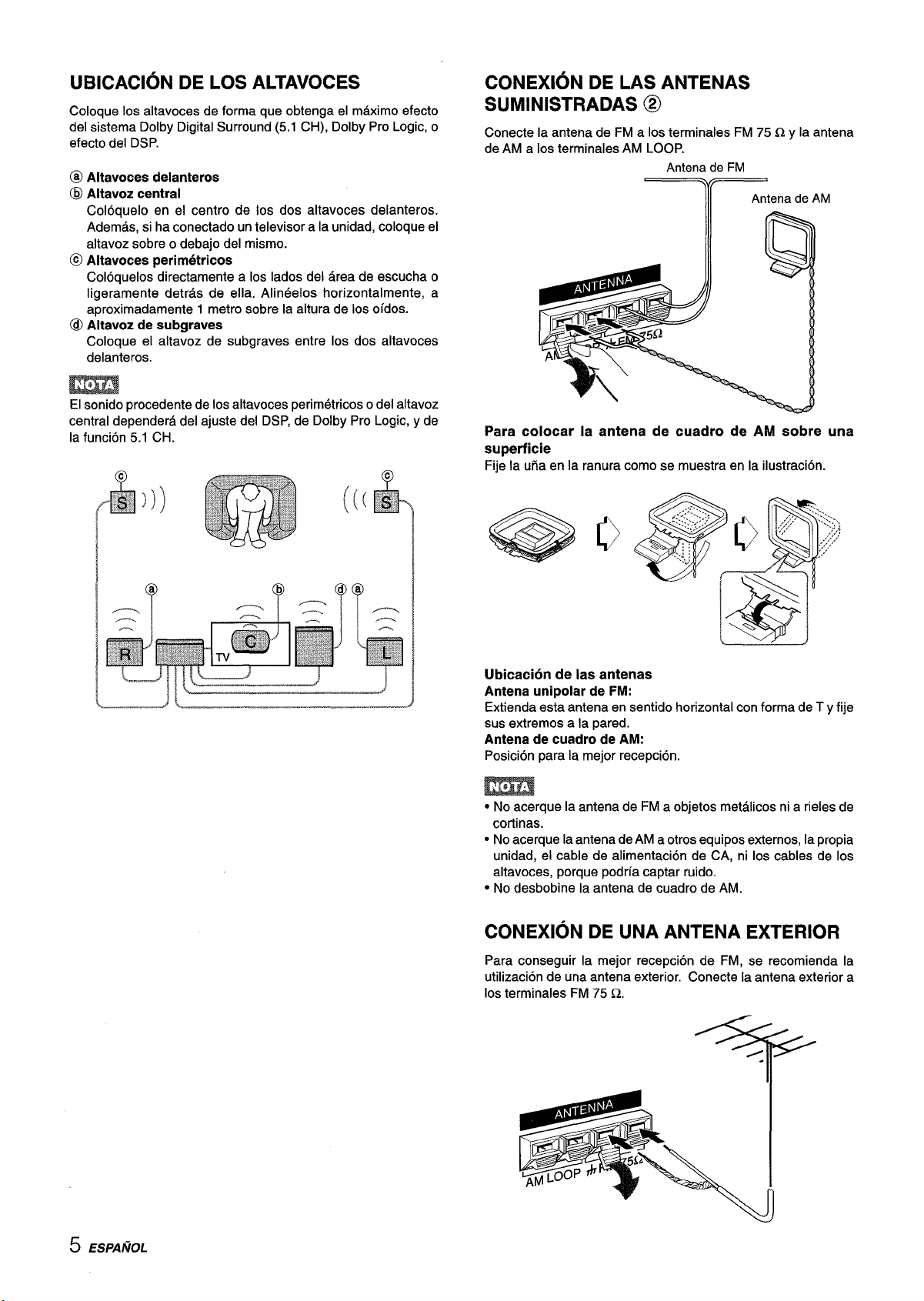
UBICACION DE LOS ALTAVOCES
Coloque Ios altavoces de forma que obtenga el maximo efecto
del sistema Dolby Digital Surround (5.1 CH), Dolby Pro Logic, o
efecto del DSP.
@ Altavoces delanteros
@ Altavoz central
Coloquelo en el centro de Ios dos altavoces delanteros.
Ademas, si ha conectado un televisor a la unidad, coloque el
altavoz sobre o debajo del mismo.
@ Altavoces perimetricos
Coloquelos directamente a Ios Iados del area de escucha o
Iigeramente detras de ells. Alineelos horizontalmente, a
aproximadamente 1 metro sobre la altura de Ios oidos.
@ Altavoz de subgraves
Coloque el altavoz de subgraves entre Ios dos altavoces
delanteros.
El sonido procedente de Ios altavoces perimetricos o del altavoz
central dependera del ajuste del DSP, de Dolby Pro Logic, y de
la funcion 5.1 CH.
I @
@
@@
I
CONEXION DE LAS ANTENAS
SUMINISTRADAS @
Conecte la antena de FM a Ios terminals FM 75 Cly la antena
de AM a Ios terminals AM LOOP.
Antena de FM
Ill
Antena de AM
Para colocar la antena de cuadro de AM sobre una
superficie
Fije la ufia en la ranura como se muestra en la ilustracion.
Ubicacion de Ias antenas
Antena unipolar de FM:
Extienda esta antena en sentido horizontal con forma de T y fije
sus extremes a la pared.
Antena de cuadro de AM:
Position para la mejor recepcion,
● No acerque la antena de FM a objetos metalicos ni a rieles de
cortinas.
● No acerque la antena de AM a otros equipos externos, la propia
unidad, el cable de alimentacion de CA, ni Ios cables de Ios
altavoces, porque podria captar ruido.
● No desbobine la antena de cuadro de AM,
CONEXION DE UNA ANTENA EXTERIOR
Para conseguir la mejor recepcion de FM, se recomienda la
utilization de una antena exterior. Conecte la antena exterior a
Ios terminals FM 75 fl.
5 ESPANOL

SOB13E EL CONTROLADOR REMOTO
lnsercir5n de Ias piias
Quite la tapa del compartimiento de Ias pilas de la parte posterior
del controlador remoto e inserte dos pilas R6 (AA).
MODO DE AHORRO DE
-l_.l__
ENERGhl, (ECO)
9
5!_____–
U Indicador POWER (!)STANDBY/ON
R6(AA)
Si aiusta esta unidad en el modo ECO, el consumo de energia
Cuandlo reemplazar Ias pilas
La distancia maxima de operation entre el controlador remoto y
el sensor de la unidad debera ser de aproximadamente 5 metros.
Cuando esta distancia se reduzca, reemplace Ias pilas por otras
nuevas.
Utilization del controlador remoto
Las instrucciones de este manual se refieren principalmente a
Ios botones de la unidad principal. Los botones del controlador
remoto con Ios mismos nombres que Ios de la unidad principal
tambien podran utilizarse.
* Cuando no vaya a utilizar la unidad durante mucho tiempo,
extraigale Ias pilas para evitar la posible fuga de su electrolito.
● Es posible que el controlador remoto no funcione correctamente
cuando:
- La l(nea de vision entre el controlador remoto y el sensor de
control remoto del interior del visuaiizador este expuesta a
una Iuz intensa como, por ejemplo, la Iuz solar directs.
- Est6n utilizandose cerca otros controladores remotos (de un
televisor, etc.).
se reducira tal corno se indica a continuation.
El ajuste initial del modo ECO es ON.
● Si lahors actual esta ajustada, laindication de reloj desalparece
inmediatamente,
* Mientras la alimentacion se encuentra desccmectada, se
apagan todos Ic)s indicadores Iuminosos y solo permanece
iluminado en color rojo el indicador POWER (!)STANDEIY/ON.
Para cancelar ell modo ECO
1 Presione el boton ECO para mostrar ECO MODE mientras la
unidad se encuentra encendida.
2 Dentro de 4 segundos, presione el boton ENTER.
3 Dentro de 4segundos, gire MULTI JOG para seleccionar ECO
OFF.
El modo se ajustara de forma automatic despues de 4
segundos. Tambien se ajustara si el boton ENTER se presiona
en un plazo de 4 segundos despues del paso :3.
ESPAIfiOL 6

ANTES DE LA OPERACION
POWER TAPE MONITOR
Indicadores de funcion
PHONES I FRONT SPEAKERA,B I ENTER
ECO MULTI JOG
Para conectar la alimentacion de la unidad
Presione el boton POWER.
La operation sera posible despues de cuatro segundos. Cuando
se presiona el boton POWER para encender la unidad, se
muestra el nivel de volumen (VOL) o el nombre de funcion, uno
detras del otro.
El indicador de la funcion seleccionada se ilumina en color rojo
y Ios demas indicadores se iluminan en verde.
Para cambiar el nivel de brillo del visualizador
1
2
3
Presione ECO para que aparezca “ECO MODE.
Dentro de 4 segundos, gire MULTI JOG para mostrar DIM
MODE y presione el boton ENTER en un plazo de 4 segundos.
Dentro de 4 segundos, gire MULTI JOG para seleccionar el
modo de atenuador, tat como se muestra a continuation.
El modo se ajustara de forma automatic despues de 4
segundos. Tambien se ajustara si el boton ENTER se presiona
dentro de 4 segundos despues del paso 3.
DIM OFF =DIMMER 1- DIMMER 2- DIMMER 3
DIM-OFF:
DIMMER 1:
DIMMER 2:
DIMMER 3:
El visualizador normal.
La iluminacion del visualizador es mas tenue
que 10habitual.
La iluminacion del visualizador es mas tenue
que con DIMMER 1.
La iluminacion dei visualizador es mas tenue
que con DIMMER 2. Los indicadores de funcion
se apagan.
Seleccion del sistema de altavoces delanteros
Para utilizar el sistema de altavoces A: Ponga el boton FRONT
SPEAKERS A en =ON.
Para utilizar el sistema de altavoces B: Ponga el boton FRONT
SPEAKERS Ben =ON.
Para utilizar ambos sistemas de altavoces: Ponga ambos botones
en =ON.
Para desconectar uno de Ios sistemas (o ambos sistemas) de
altavoces, ponga el boton (o Ios botones) en IOFF.
Como Ios sistemas de altavoces delanteros A y B estan
conectados en serie:
- El sonido se reducira Iigeramente al utilizar ambos sistemas
de altavoces.
- Nose oira sonido si Ios botones FRONT SPEAKERS A y B
estan en -ON cuando solamente haya conectado un sistema
de altavoces.
Utilization de auriculares
Conecte Ios auriculares con clavija estereo estandar (6,3 mm
de dia.) en la toma PHONES. Cerciorese de que Ios botones
FRONT SPEAKERS A y B esten en IOFF. De 10contrario, el
sonido saldria a traves de Ios altavoces.
Cuando enchufe Ios auriculares, se cancelara automaticamente
la funcion 5.1 CH, Dolby Pro Logic, o el sistema del DSP.
Para desconectar la alimentacion de la unidad, presione
el boton POWER.
7 ESPANOL

AWSTE DEL SONIDO A SU
GUSTO
DOWN,UP VOLUME
I MUTE I
BALANCE
VOL
T-BASS
CONTROL DEL VOLUMEN
Gire el control VOLUME de la unidad o presione Ios botones
VOL del controlador remoto.
El nivel del volumen se mostrara en elvisualizador durante cuatro
segundos. Este nivel podra ajustarse entre O y MAX (50).
Parpadea si se ajusta por encima del nivel 44.
El nivel del volumen permanecera memorizado incluso
despues
de haber desconectado la alimentacion. Sin embargo, si
desconecta la aiimentacion cuando et nivel del volumen este
ajustado a mas de 21, la proxima vez que vuelva a conectarla
se ajustara automaticamente a 20.
Para
ajustar el equilibria entre Ios altavoces delanteros
izquierdolderecho
Presione el boton BALANCE para hater que se visualice “L/R
OdB”. [)espues presione repetidamente DOWN o UP antes de
cuatro segundos.
Tenga en cuenta que el equilibria entre Ios aitavoces delanteros
para Ios modos 5.1 CH y Dolby Pro Logic tambien cambiara.
Para .sHenciar temporalmente el sonido
Presione el boton MUTING (–20 dB).
En el visualizador aparecera “MUTE ON” durante cuatro
segundos. Mientras el sonido este silenciado, el indicador de
funcion seleccionado parpadeara. Para restablecer el sonido,
vuelva a presionar el boton MUTING.
SISTEMA SIJPER T-BASS
El sistema T-BASS realza el realismo del sonido de baja
frecuencia.
Presione el boton T-BASS.
Cada vez que presione el boton, el nivel cambim%.
Seleccione a su gusto uno de Ios tres niveles o Iii position cie
cancelacion.
1
L,
L
..=
—
—
•:+::+~:,+
J
wmEmN
Iamimi
(cancelacion)
El sonido de baja flrecuencia puede distorsionarse cuando utilice
el sistema T-BASS con un disco o un casete cuyo sonido cle
baja frecuencia haya sido acentuado originalmente. En este case,
cancele el sistema T-BASS.
AJUSTE DEIL SONIDO DURANTE LA
GRABACION
El volumen y el tono de salida de Ios altavoces o de Icls
auricu[ares podran variarse Iibremente sin que se vea afectaclo
el nivel de grabacion.
ES/JA/ibL{3

ECUALIZADOR GRAFICO
ELECTRONIC
GEQ
Esta unidad dispone de Ios cinco modos de ecualizacion
siguientes.
ROCK: Acentua el sonido de graves y agudos.
POP: Ofrece mas presencia a Ias votes y a la gama media.
JAZZ: Acentua Ias frecuencias bajas para musics de tipo jazz.
CLASSIC: Ofrece sonido rico con graves profundos y agudos
delicados.
BGM: Ofrece tono calmado con graves y agudos suprimidos.
Presione el bot6n GEQ (ecualizador grafico) y gire MULTI
JOG hasta que aparezca el modo de ecualizacion que
desee.
Los modos GEQ se muestran de forma ciclica, de la siguiente
forma.
r
ROCK—
PoP— JAZZ —
CLASSIC
— BGM
1
L.---w
—M3—
M2—
Ml ~
,------- Modomanual -------:
El nombre del modo seleccionado se muestra durante cuatro
segundos y el indicador F aparece a la izquierda del nombre
de modo seleccionado.
Modo seleccionado
Para cancelar el modo seleccionado
Presione el boton GEQ de nuevo. En el visualizador aparecera
“GEQ OFF.
Para seleccionar con el controlador remoto
Presione repetidamente el boton GEQ hasta que se visualice el
modo de ecualizacion deseado.
Es posible seleccionar cinco modos preajustados, Ios modos
manuales Ml a M4 y “GEQ OFF.
AJUSTE DE NUEVAS CURVAS DE
ECUALIZACION
Es posible almacenar hasta 4 curvas de ecualizacion como Ios
modos manuales Ml a M4.
1
2
3
4
5
6
7
1 3,6
2 1,5,7
Presione el boton GEQ y presione el boton
ENTER dentro de 4 segundos.
Presione el boton DOWN o UP para seleccionar
una frecuencia.
Parpadea el indicador de nivel de la frecuencia seleccionada.
Gire MULTI JOG para ajustar el nivel de la
frecuencia seleccionada.
Repita Ios pasos 2 y 3 para crear la curva de
ecualizacion que desee.
En Ios pasos 2 y 3, la unidad vuelve al modo normal si nose
realiza ninguna operation durante aproximadamente 8
segundos.
Dentro de 8 segundos, presione el boton ENTER.
Aparece “GEQ Ml” en el visualizador.
Gire MULTI JOG para seleccionar un ntimero
preajustado de Ml a M4.
Presione el boton ENTER.
La curva de ecualizacion se almacena.
El numero preajustado seleccionado y la curva de
ecualizacion se muestran durante unos segundos cada uno.
Para ajustar temporalmente la curva de ecualizacion
grafica
Siga 10spasos 1 a 4 anteriores.
La curva GEQ ajustada se conserva antes de cambiar o cancelar
el modo de ecualizacion grafica (GEQ).
Para seleccionar la curva preajustada manualmente
Presione el boton GEQ y gire MULTI JOG hasta que aparezca
el numero preajustado que desee.
● El sistema GEQ se cancela automaticamente si:
- Activa Dolby Pro Logic
- Selecciona la funcion 5.1 CH
● El sistema GEQ no puede activarse mientras se encuentra
seleccionada la funcion 5.1 CH.
9 ESPAfiOL

SONIDO PERIMETRICO DEL
PROCESADOR DE SENAL DIGITAL
DSP MULTIJOG
DOWN,UP
DSP
MANUAL
SELECT
Los circuitos de sonido perimetrico del procesador de sefial
digital (DSP) pueden recrear el efecto de sonidos reflejados en
paredes o techos, para ofrecer la presencia de sonido de
ambientes reales. Existen cuatro modos correspondientes a Ios
modos de ecualizacion grafica. Los modos de ecualizacion se
seleccionaran automaticamente, y tambien podra seleccionar o
desactivarlos a su gusto.
Presione el boton DSP y gire MULTI JOG hasta que
aparezca el modo DSP que desee.
El nolmbre de modo seleccionado aparece durante cuatro
segundos y Ios indicadores
➤ aparecen a la izquierda del nombre
DSP seleccionado y el nombre de modo GEQ correspondiente.
Modo del DSP seleccionado
Modo GEQ correspondiente
Para cancelar el modo seleccionado
Presione el botorl DSP de nuevo. En el visualizador aparecera
“DSP OFF. Incluso aunque haya cancelado el rnodo del D!>P
seleccionado, e! modo del GEQ adecuado o seleccionado
permanecera en el visualizador.
Para seleccionar con et controlador remotol
Presione repetidamente el boton DSP hasta que se visualice el
modo del DSP deseado.
I
Es posible seleccionar cuatro modos del DSP y “DSP CIFF.
Para ajustar el volumen y el equiiibrio de Ios altavoces
perimetricos
Presione et boton MANUAL SELECT del controlaclor remoto dos
o tres veces mientras el sistema DSP se encuantra activado
para mostrar “S-Fl OdB (para el altavoz perimetrllco derecho) o
“S-L OdB (para el altavoz perimetrico izquierdo). Acontinuaci6n,
presione el botor] DOWN o UP varias veces dentro de cuatro
segundos.
Tenga presente que tambi6n cambian el volumen y equilibria de
Ios altavoces perimetricos de Ios modos 5.1 CH y Dolby F)ro
Logic.
m
● El sistema del [)SP se cancelara autornaticamente:
- cuando active el modo Dolby Pro Logic
- Cuando seleccione la funcion 5.1 CH
● El sistema DSP no podr~ activarse:
- cuando haya seleccionado la funcion 5.1 CH
- cuando haya enchufado unos auriculares
Cuando la fuente de musics sea monoaural
Seleccione LIVE para obtener un efecto estereo simulado. Si
selecciona DANCE, HALL o ARENA no oira sonido a traves de
10saltavoces perimetricos.
,ESPAfiOL 10

SELECCION DE UNA FUENTE DE
Para seleccionar la fuente de video
AUDIO/ViDEO
1 Seleccione una de Ias funciones (excepto TUNER).
2 Presione el boton ENTER para mostrar VIDEO1.
3 Gire MULTI JOG para seleccionar VIDEO 20 VIDEO 3.
FUNCTION
Indicadores de funcion ENTER
Para cambiar el nombre visualizado para
el VIDEO 1 y el VIDEO 2
Si VIDEO 1 se encuentra seleccionado, VIDEO 1 se muestra
inicialmente. Es posible cambiar a DVD o MD.
Presione el boton VIDEO 1/5.1CH/BAND mientras presiona el
boton ENTER.
Para utilizar la funcion 5.1CH, presione el boton VIDEO 1/5.1CH/
BAND. El nombre de funcion cambiara a “5.1 ch IN” y se
seleccionara la fuente conectada a Ios terminals 5.1 INPUT.
Para continuar, presione el boton de nuevo para que se muestre
el nombre de la funcion seleccionada.
DOWN;UP
I
MULTI
JOG
VIDEO 1/5. CH/BAND
Seleccione la fuente de programas.
Gire el selector FUNCTION o presione et boton TAPE
MONITOR. El indicador de funcion seleccionado parpadea
en color rojo.
1
El nombre mostrado para el boton VIDEO 2 puede cambiarse a
VIDEO 2, LD o TV. Con la funcion VIDEO 2 seleccionada,
presione el boton VIDEO 1/5.1CH/BAND mientras presiona el
boton ENTER.
Para ajustar el nivel del sonido de la fuente
conectada
I Radio
I TUNER
I
Discos analogicos
PHONO
Discos compactos
CD
Television, etc.
AUX
El nivel de sensibilidad de entrada de cada funcirh (excepto la
funcion TUNER) podra ajustarse.
Cuando el nivel del sonido de la fuente conectada sea superior
o inferior al de TUNER, ajustelo de la forma siguiente.
Videocasetes
VIDEO lIDVDIMD,
VIDEO 2/LDiTV, VIDEO 3
Discos laser o programas de
VIDEO 2
cablevision
Minidiscos o videodiscs
VIDEO l/DVD/MD
diaitaies
1 Seleccione la funcion que desee ajustar.
Gire MULTI JOG hasta la position apropiada y reproduzca
la fuente.
Para seleccionar una funcion en ei controlador remoto
Presione el boton de funcion deseado directamente.
2
Presione repetidamente el boton UP o
DOWN.
La funcion seleccionada (excepto PHONO) dependera del
equipo conectado a Ios terminals de entrada del panel
posterior de la unidad.
Cuando utilice un giradiscos con amplificador incorporado,
desconecte la alimentacion del amplificador ecualizador. Para
mas information, consulte et manual de instrucciones del
giradiscos.
El nivel podra ajustarse entre –6 dB (MIN) y +8 dB (MAX) en
pasos de 2 dB. Ajuste el nivel de forma que el sonido salga con
el mismo nivel que el de TUNER.
23Ponga en reproduction la fuente de programas
seleccionada.
● El nivel de sensibilidad de entrada de la funcion TUNER no
podra ajustarse.
● Tampoco podra ajustarse el de TAPE MONITOR.
Aunque haya seleccionado TAPE MONITOR y et indicadorTAPE
MONITOR se haya vuelto rojo, al presionar el boton UP o DOWN,
el nivel de la funcion indicada en el visualizador cambiara.
Ajuste el sonido,
Sobre la fuente de vfdeo para el monitor o
el televisor
Fuente de video seleccionada
Vi: VIDEO 1, V2: VIDEO 2, V3: VIDEO 3
f-a fuente de v[deo seleccionada se indicara en el visualizador,
y la sefial de video aplicada a la toma MONITOR VIDEO OUT
saldra al televisor.
1 I
ESPANOL
 Loading...