


360 XC Land 2000
Table of contents
 Loading...
AIRSTREAM 360 XC LAND YACHT OWNERS MANUAL
INTRODUCTION
The Owners Manual for your new Airstream Motorhome is designed to respond to the most frequent
inquiries regarding the operation, function and care of the many systems that make modern motor homing a
joy.
Airstream realizes our customers possess varying degrees of expertise in the area of repairing and
maintaining the appliances in their motorhome. For this reason, the service and trouble-shooting
information found in this manual is directed toward those with average mechanical skills. We also realize
you may be more familiar in one area than you are in another. Only you know your capabilities and
limitations.
We want you to use this manual, and hope you will find the information contained in it useful, however,
should you ever feel you may be "getting in over your head" please see your dealer to have the repairs
made.
The operation and care of component parts such as chassis, refrigerator, furnace, water heater and others
are explained in this manual. However, you will also find the manufacturer's information supplied in a
packet included with this manual.
All information, illustrations and specifications contained in the literature are based on the latest product
information available at the time of publication approval.
Throughout this manual
damage equipment. "Warning" notes the possibility of personal injury if not observed.
: If and when new materials and production techniques are developed which can improve the quality
Note
of its product, or material substitutions are necessary due to availability, Airstream reserves the right to
make such changes.
The next page of this manual is a table of contents. Point your cursor to the subject, colored blue, you
would like to research. Right click your mouse while it is on the subject title and you will be taken to that
area of the manual.
To get back to table of contents, click on the back arrow in the tool bar at the top of the document. The
arrow will be lighted.
The next two pages contain an index of subject material in alphabetical order.
CAUTION
and
WARNING
© Airstream, Inc. 2000
notations are used. Failure to observe "caution" can

AIRSTREAM 360 XC LAND YACHT OWNERS MANUAL
A. WARRANTY AND SERVICE
Warranty
Warranty Explanation
Service
Reporting Safety Defects
Maintenance Schedule
B. DRIVING
Wide Body Limitations
Loading
Safety, Pre-Travel Check List
Dash controls & Instruments
Trailer Towing & Driving Tips
C. CHASSIS
D. CAMPING
E. EXTERIOR
Chassis -Body Product Definition
Engine
Air Brake System Drainage
Tire/Wheels
Air Conditioner/Heater
Electric Step
Camping Safety
Smoke Alarm
Carbon Monoxide Alarm
LP Gas Detector
Overnight Stop
Winter Traveling
Condensation
Extended Stay
Slide-out Room
Campground Setup
Cleaning
Body Armor
Roof Storage, Ladder
Main Door Locks
Keyless Entry
F. INTERIOR FURNISHINGS AND
ACCESSORIES
Lounges & Tabl es
Fabric Care
Features & Fixtures
G. PLUMBING
LP (Liquid Petroleum) Gas
Water System
Water Pump
City Water Hookup
Storage and Winterizing
Faucets
Drainage System
Toilet
H. ELECTRICAL
12-volt system
Inverter
Monitor Panel
Fuses
TV Antenna
Satellite and CB Hookups
Solar Panel
110-Volt Power
Generator
I. APPLIANCES
Air Conditioner
Furnace
Refrigerator
Range/Oven
Microwave Oven
Water Heater
Power Roof Vent
SPECIFICATIONS
Coach Dimensions
Tank Capacities
Chassis Components

AIRSTREAM 360 XC LAND YACHT OWNERS MANUAL
INDEX
Air Brake System Drainage.................... C-1
Air Conditioner.........................................I-1
Air Dump Switch ................................... B-5
Air Supply Line .......................................E-2
Antenna ...................................... H-26, H-29
Appliances ................................................I-1
Automotive Fuses...................H-2, H-5, H-6
Auxiliary Start Switch ............................ B-4
Battery Disconnect Switch......................H-1
Bathroom ................................................F-3
Batteries ..................................................H-1
Bed, Rear .................................................F 1
Bottled Gas .............................................G-1
Body Armor.............................................E-1
By-Pass Valves.............................G-5, G-19
Cab Seats ................................................ B-5
Cabinets ...................................................F-3
Capacities................................................. J-1
Camping........................................D-1, D-10
Carbon Monoxide Alarm........................D-5
Carpet ...................................................F-2
Caution .....................................Introduction
Chairs (Recliners)....................................F-1
Chassis ............................................C-1, J-1
CB antenna............................................H-29
Check Valve, water pump....................... G-8
Child Restraint Device............................ B-3
Circuit Breakers..................H-2, H-31, H-32
City Water Hookup............................... G-11
Cleaning Codes........................................F-2
Cleaning, Exterior ....................................E-1
Condensation ..........................................D-9
Counter Areas..........................................F-3
Dash Air Conditioner.............................. C-4
Dash Switches......................................... B-4
Dimensions.............................................. J-1
Dinette ...................................................F-1
Door Lock........................................B-4, E-3
Drain Hose............................................ G-21
Drain Lines .................................G-18, G-21
Drain System ........................................ G-21
Drain Valves...............................G-19, G-21
Drawers ...................................................F-3
Drawings, water system........................ G-24
Driving ..................................................B-1
Electrical System ....................................H-1
Electric Cord.........................................D-10
Electric Step............................................ C-7
Engine Access......................................... C-1
Engine Block Heater............................... C-4
Escape Window ......................................D-1
Extended Stay .......................................D-10
Exterior .................................................. E-1
Faucets ........................................G-5, G-12
Fabrics, Cleaning ....................................F-1
Filter, Water (Faucet)........G-12, G-14, G-17
Fire Extinguisher.....................................D-1
Floor Tile .................................................F-1
Furnace ....................................................I-2
Fuses ..................................H-2, H-5, H-6
Gas Lines, LP..........................................G-4
Gas, LP ..........................................D-6, G-1
Gauges ..................................................B-4
Generator ............................B-4, D-10, H-31
Ground Fault Interrupter.......................H-31
GVWR ..................................................B-1
GCWR ........................................... B-1, J-1
Hitch Load ............................... B-1, B-5, J-1
Holding Tanks.......................................G-21
Humidity................................................. D-9
Interior ...................................................F-1
Inverter/Charger......................................H-1
Keyless Door Lock ................................. E-3
Lavatory, Cleaning...................................F-3
Leveling ..............................D-8, D-10, H-20
Leveling Jacks.....................D-8, D-10, H-20
Lights ..................................................H-2
Loading .......................................... B-1, H-2
Locks .................................................. E-3
Lounge ...................................................F-1
LPG System............................................G-1
LP Leak Detector.................................... D-7
Maintenance Schedule ............................A-7
Microwave Oven.......................................I-4
Monitor Panel..............................G-21, H-22
Mirrors, Remote Control......................... B-5

AIRSTREAM 360 XC LAND YACHT OWNERS MANUAL
Overnight Stop ........................................ D-8
Plumbing................................................. G-1
Power Cord........................................... D-10
Power Seats............................................. B-5
Protective Film, Front End.......................E-1
Range/Oven ..............................................I-4
Range Exhaust..........................................I-4
Reporting Safety Defects........................ A-6
Refrigerator...............................................I-3
Roof Vent..................................................I-6
Roof Storage, Ladder ...............................E-2
Safety Defects, Reporting....................... A-6
Safety ................... B-2, D-1, G-1, G-2, I-5
Satellite antenna..........................H-29, H-30
Seat Belts................................................ B-3
Service ..................................................A-5
Sewer Hose................................. D-10, G-21
Shades ...................................................F-2
Shower Stall............................................. F-3
Sinks ...................................................F-3
Slide-out................................................D-10
Smoke Alarm.......................................... D-2
Sofa ...................................................F-1
Solar Power........................................... H-31
Specifications........................................... J-1
Step, Electric........................................... C-7
Step Cover .............................................. C-7
Storage ................................................G-18
Switches, Armrest-Dash ......................... B-4
Table ...................................................F-1
Tank Capacities........................................ J-1
Tank Drain....................................D-8, G-21
Tank, Sewage........................................G-21
Tank, Water.............................................G-5
Tank, LPG...............................................G-1
Tires, Support..........................................C-2
Toilet ................................................G-23
Towing ..................................................B-5
TV Antenna...........................................H-26
Upholstery................................................F-1
Ventilation ..............................................D-9
Walls ...................................................F-3
Washing/Waxing..................................... E-1
Warning .....................................Introduction
Warranty .........................................A-1, A-4
Warranty Transfer...................................A-3
Warranty Exclusions...............................A-4
Waste System........................................G-21
Water Filter, Faucet ..............................G-12
Water Heater.............................................I-5
Water Hookup .............................D-10, G-11
Water Pump ............................G-6, G-7, G-9
Water System................................G-5, G-20
Water Tank Fill.......................................G-5
Water Tank Cleaning....................G-6, G-22
Wide Body Limitations........................... B-1
Windshield Wiper................................... E-2
Winterizing ...........................................G-18
Winter Traveling.....................................D-8
Wiring, 12 Volt.......................................H-3
Wiring Diagrams, 12 Volt.......................H-4
Wiring, 110 Volt System......................H-31
Wiring Diagram, 110 Volt..........H-32, H-34

AIRSTREAM 360 XC LAND YACHT OWNERS MANUAL
AIRSTREAM INC.
LIMITED WARRANTY
AIRSTREAM LAND YACHT MOTORHOME
WARRANTY COVERAGE
When you buy a new Airstream Motorhome from an authorized Airstream dealer, Airstream, Inc., warrants
the motorhome from defects in material and workmanship as follows:
BASIC WARRANTY PERIOD
This warranty is for 30,000 miles (40,000 Kilometers) or two years, whichever comes first, beginning when
the vehicle is delivered to the first retail customer or first placed into demonstrator service. This warranty
must have started prior to the accumulation of 4,000 miles in order to be valid.
ITEMS COVERED
Any part of the motorhome or any component equipment installed by the factory is covered by the basic
warranty
•
•
•
The above items will be handled by their respective service points and according to their written policy.
This limited warranty does not include failure caused by accident, abuse, normal wears, overload or any
cause not attributable to a defect in original material or workmanship of the motorhome or component
equipment as installed by the factory.
LIMITATION OF IMPLIED WARRANTIES
All warranties of merchantability and fitness for a particular purpose, whether written or oral, express or
implied, shall extend only for a period of two years from the date of original purchase, or 30,000 miles,
whichever comes first. There are no other warranties, which extend beyond those described on the face
hereof and which expressly excludes conditions resulting, from normal wear, accident, abuse, exposure or
overload. Some states do not allow limitation on how long an implied warranty lasts, so the above
limitations may not apply to you.
AIRSTREAM'S RESPONSIBILITY
The basic
purchase or 30,000 miles, whichever comes first, and the application date of all warranties is that indicated
on the owner's identification card. Defects in items covered under this Warranty will be corrected without
cost upon the return, at the owner's expense, of the motorhome or defective part to an authorized Airstream
dealer.
the following items, which are
except
House Batteries
Automotive Chassis
Generator
Airstream Limited Warranty
not covered:
applies for a period of two years from the date of original
A-1

AIRSTREAM 360 XC LAND YACHT OWNERS MANUAL
CARE AND MAINTENANCE
This warranty covers only defective material and/or workmanship; adjustments are made at the factory
prior to shipment, and rechecked by the dealer prior to delivery to the customer. Adjustments thereafter
become a customer responsibility.
The owner is also responsible for following all recommendations, instructions and precautions contained in
the Airstream Motorhome Owner's Manual and the individual manuals furnished by the chassis, appliance
and other manufact urers.
INSTALLATIONS NOT COVERED
Airstream, Inc., does not accept any responsibility in connection with any of its motorhomes for additional
equipment or accessories installed at any dealership or other place of business, or by any other party. Such
installation of equipment or accessories by any other party will not be covered by the terms of this
warranty.
IF REPAIRS ARE NEEDED
If your motorhome needs repairs under the terms of the basic Airstream Limited Warranty, you should:
1. Take your motorhome to your selling dealer or other Authorized Airstream Dealer.
2. If the dealer is incapable of making the repair, request that he contact the Service Administration
Department at Airstream, Inc., for technical assistance.
3. If repairs are still not made, the customer should contact:
AIRSTREAM, INC.
419 W. Pike Street - P.O. Box 629
Jackson Center, Ohio 45334-0629
Attention: Owner Relations Dep artment
Furnish the following information:
The complete serial number of the motorhome
•
Mileage
•
Date of original purchase
•
Selling dealer
•
Nature of service problem and steps or service, which have been performed. (The owner
•
may be directed to another dealer at the owner's expense.)
4. If, after taking the above steps, repairs are still not complete, the Airstream owner may request the
motorhome be allowed t o be brought to t he Factory Service Center at the owner's expense.
DEALER REPRESENTATION EXCLUDED
The full extent of the basic
explanation of the basic
Manual. Airstream Inc. will not be responsible for additional representations or implied warranties made by
any of its dealers to the extent those representations are not a part of, or are contrary to, the terms and
conditions of the basic
Airstream Limited Warranty
Airstream Limited Warranty
Airstream Limited Warranty
is set forth in detail in the folder, and in the
covered in the Airstream Motorhome Owner's
.
A-2

AIRSTREAM 360 XC LAND YACHT OWNERS MANUAL
CONSEQUENTIAL AND INCIDENTAL DAMAGES
Airstream, Inc., will not be responsible for any consequential or incidental expenses or damages
resulting from a defect. Incidental expenses include, but are not limited to: travel expenses, ga so line,
oil, lodging, meals, telephone tolls, and loss of work and loss of use of the motorhome. Some examples
of consequential damages would be: stained curtains due to rain leaks or delaminated floor caused by
a plumbing leak. Some states do not allow the exclusion or limitation of incidental or consequential
damages, so the above limitation or exclusion may not apply to you.
WARRANTY TRANSFER
The basic
warranty period. Warranty transfer application forms are available from your dealer or the Airstream Inc.
Service Administration Department.
Airstream Limited Warranty
is transferable to subsequent owners for the duration of the
CHANGES IN DESIGN
Airstream Inc. reserves the right to make changes in design and improvements upon its product without
imposing my obligation upon itself to install the same upon its products theretofore manufactured.
This warranty gives you specific legal rights, and you may also have other rights, which vary from
state to state.
Thor Industries
Airstream Inc.
419 West Pike Street
Jackson Center, Ohio 45334
937-596-6111
A-3

AIRSTREAM 360 XC LAND YACHT OWNERS MANUAL
WARRANTY EXPLANATION
Along with your new Airstream motorhome you have purchased t he Airstream Limited Wa rranty. Read
your Limited Warranty carefully. It contains the entire agreement with respect to Airstream's obligation on
the Limited Warranty on your new vehicle. The terms of the Limited Warranty, and only those terms, will
define Airstream's responsibility. When you receive your Limited Warranty file it for safekeeping.
Upon proof of purchase date to any Airstream Dealer Service Center, defects in materials or workmanship
will be repaired or replaced without cost to the owner for a period of twenty four (24) months from the
original purchase date, or 30,000 miles, whichever occurs first. Written warranties of some manufacturers
of components of the motorhome will be honored by Airstream for the duration on that manufacturer's
warranty.
Items such as motorhome chassis, engine, tires, batteries and generator are serviced by their respective
manufacturers and will be handled by their service centers according to the terms of their written policy.
Any warranty forms from these manufacturers should be completed promptly, preferably at time of
purchase.
Your motorhome chassis is pre-checked by its manufacturer before delivery to Airstream. All service to the
chassis must be performed by the manufacturer according to the manufacturer's warranty and service
policies. Literature is supplied with each Airstream motorhome, which gives important information
concerning its warranty coverage; however, the Airstream Limited Warranty covers the chassis heater,
defrosters, windshield wiper blade, motor, washer, LP gas bottle and gas regulator.
Paint and appearance ite ms, which sho w imper fections, should b e brought to the a ttention of your dealer at
the time of delivery and during pre-delivery inspection. Normal deterioration by use and exposure is not
covered by the Airstream Limited Warranty.
Damage to enameled or porcelain surfaces resulting from abrasion, collision or impact, and broken window
glass are not covered by the Airstream Limited Warranty.
The Airstream Limited Warranty Excludes:
Normal Wear:
Items such as water purifier packs, curtains, upholstery, floor coverings, window, door and vent seals may
show wear within the one year Limited Warranty period depending upon the amount of usage, weather and
atmospheric conditions.
Accident
Damage caused by accident is usually visible, and we strongly urge our dealers and customers to inspect
the motorhome upon delivery for any damage caused by accident while being delivered to the dealer, or
while it is on the dealer's lot. Damage of this nature becomes the dealer's or your responsibility upon
acceptance of the motorhome. GLASS BREAKAGE, whether obviously struck or mysterious, is always
accidental and covered by most insurance policies.
A-4

AIRSTREAM 360 XC LAND YACHT OWNERS MANUAL
Abuse
Lack of customer care and/or improper maintenance, including failure to comply with the terms of the
Owner’s Manual, or fa i lure to heed proper vehicle operation shown by the dash instruments is not covered
by warranty.
Exposure
Deterioration by sunlight is possible to such items as tires, curtains or upholstery. Steel or metal surfaces
are subject to the elements, causing rust and corrosion, which is normal, and beyond the control and
responsibility of Airstream.
Overload
Overload Damage due to loading beyond capacity or to cause improper balance is not covered by the
Airstream Limited Warranty. The Airstream motorhome body is engineered to properly handle any normal
load. There are limits to the amount of load that can be safely transported depending upon speed and road
conditions. If these limits have been exceeded the Airstream Limited Warranty will not cover resulting
damage. For additional information on the load capacity of your motorhome consult your Owner's Manual
or gross vehicle weight rating plate. Each motorhome is aligned during the last quality inspection. These
tolerances will only change if the motorhome is subjected to abuse, such as dropping off a sharp berm,
striking a curb, or hitting a deep hole in the road. Such damage would be considered as resulting from an
accident which risks are not covered under the warranty. Abnormal tire wear and/or wheel alignment
resulting from such da mage is not covered under the terms of the warranty.
SERVICE
The Airstream Silver Key Delivery Program is an exclusive Airstream program. Before leaving the factory
each and every vital part of the motorhome is tested for performance. Each test is signed and certified by an
inspector. After the motorhome arrives on your dealer's lot all of these vital parts and systems are again
tested. When you take delivery of your new motorhome you will receive a complete checkout.
Please contact your dealer if you need service. Major service under your Airstream Limited Warranty is
available thr ough our nationwide networ k of Airstream Dealer Service Centers. An up-to-date list of Dealer
Service Centers has been provided with your new motorhome. This list is current as of the date of
publication.
Occasionally dealerships change, or new dealers are added who may not appear on this list. For this reason,
it is suggested that you contact your local dealer from time to time and bring your l i s t up to date. H e can
also provide you with additional copies if you need them.
ALL CENTERS OPERATE ON AN APPOINTMENT BASIS FOR THE UTMOST EFFICIENCY.
When you require service from the Airstream Factory Service Center, or a Certified Dealer Service Center,
please contact the service manager for an appointment, and kindly inform him if you are unable to keep the
appointment date or wish to change it.
Service may be arranged at the Factory Service Center by contacting the Service Coordinator at
Airstream Factory
Service Center
419 W. Pike Street P.O. Box 629
Jackson Center, Ohio 45334-0629
Phone: 937-596-6111
Fax: 937-596-6802
A-5

AIRSTREAM 360 XC LAND YACHT OWNERS MANUAL
You Should Also be Aware of the Follo wing:
Airstream is not responsible for any consequential or incidental damages incurred as a result of any defect.
Consequential damages include, but are not limited to, travel expenses, gasoline, oil, lodging, meals,
telephone tolls, loss of work and loss of use of the motorhome.
In the event of a defect, the owner must take all reasonable corrective action to lessen the damages, which
might result from such defect. Airstream will not be responsible for damages, which could have been
avoided.
Airstream's responsibility is defined solely by the Airstream Limited Warranty and Airstream is not
responsible for or bound by representations or warranties made by any of its dealers.
Your Airstream Limited Warranty is transferable to subsequent owners of the motorhome, but only for the
duration of the warranty period. Warranty transfer application forms are available from your dealer or the
Airstream factory.
REPORTING SAFETY DEFECTS
If you believe that your vehicle has a defect, which could cause a crash or could cause injury or death, you
should immediately inform the National Highway Traffic Safety Administration (NHTSA) in addition to
notifying Airstream, Inc.
If NHTSA receives similar complaints, it may open an investigation, and if it finds that a safety defect
exists in a group of vehicles, it may order a recall and remedy campaign. However, NHTSA cannot become
involved in individual problems between you, your dealer, or Airstream, Inc.
To contact NHTSA you may either call the Auto Safety Hotline toll-free at 1-800-424-9393 (or 366-0123
in Washington, D.C. area) or write to: NHTSA, U.S. Department of Transportation, Washington, D.C.
20590. You can also obtain other information about motor vehicle safety from the Hotline.
A-6

AIRSTREAM 360 XC LAND YACHT OWNERS MANUAL
MAINTENANCE SCHEDULE
WARNING: FAILURE TO MAINTAIN YOUR COACH CAN CAUSE PREMATURE AND
UNEXPECTED PARTS BREAKAGE AND/OR ERRATIC OPERATION THAT MAY BE
HAZARDOUS.
Note: See Freightliner and appliance manufacturer's literature for further information.
EVERY 1,000 MILES OR 60 DAYS
Escape Window Check operation of latches and upper hinge.
Smoke Alarm Test and replace battery as required.
CO, LPG and Smoke Alarm Test and replace battery as required.
GFI Circuit Breaker Test and record.
EVERY 5,000 MILES OR 90 DAYS
Exterior Door locks Lubricate with dry graphite
Exterior Hinges Lubricate with light household oil
LPG Regulator Check bottom vent for obstructio ns
Main Door Striker Pocket Coat with paraffin.
Wheel Lug Bolts Torque to 450-500 ft. lbs.
Range Exhaust Hood Clean fan blades and wash filter.
Roof Vent Elevator Screws Lubricate with light household oil
Main Door Step Check and lubricate moving parts.
EVERY 10, 000 MILES OR 6 MONTHS
Exterior Clean and wax.
Hitch Check bolts and welds
EVERY YEAR or 12,000 miles
Battery Clean, neutralize and coat terminals with petroleum jelly.
LP Tank Clean, neutralize and coat terminals with petroleum jelly.
Seams Check and reseal exterior seams, windows, lights and vents if
necessary. Reseal with Bostik urethane sealant or equivalent
as needed.
A-7

AIRSTREAM 360 XC LAND YACHT OWNERS MANUAL
MAINTENANCE RECORDS
DATE DEALER SERVICE PERFORMED
A-8
AIRSTREAM 360 XC LAND YACHT OWNERS MANUAL
DRIVING
WIDE BODY LIMITATIONS
Vehicles with overall body width greater than 96" are known as "wide bodies. Wide body vehicles are
restricted to use on main highways in certain states. A vast majority of states allow 102" body width on all
highways, but wide body width is not allowed on all federal highways in the United States. Your dealer
may be able to furnish more specific information. If you are concerned about vehicle width, we invite you
to consider other fine Thor vehicles offered in the standard 96" width.
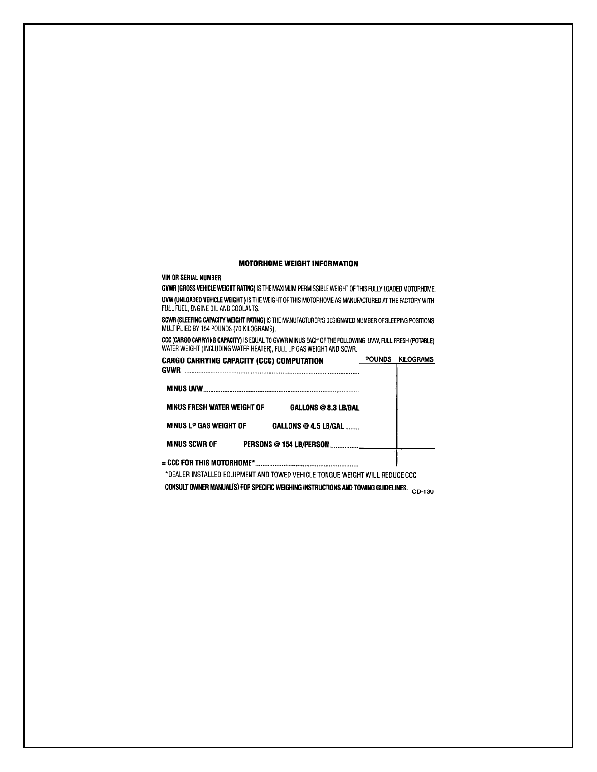
LOADING
Below is a sample of the weight information chart provided in all Airstream vehicles. This information can
be found in your vehicle on the back of the first wardrobe door on the curbside of the vehicle about 60" up
from the floor or in one of the galley overhead lockers.
The GROSS COMBINATION WEIGHT RATING on the 360XC motorhome is 31,350 pounds.
*WARNING - Do not exceed the hitch capacity of 500 lb. load and 5000 lb. tow.
The motorhomes have large fluid tanks and lots of storage areas. It gives you great flexibility in loading.
With flexibility comes responsibility. If you want to load down all the storage compartments the amount of
fluids will have to be reduced. Distribute your additional cargo as evenly as possible with the heaviest
objects located as low as possible.
Do you really want to carry 750 pounds of water to a RV park 1,000 miles away and then hook up to a city
water supply? Even if you're going to the "boondocks" you can usually fill your water tank shortly before
entering the area. Just reducing your load by 10 gallons of water lets you carry an awful lot of fishing and
camping gear.
B-1

AIRSTREAM 360 XC LAND YACHT OWNERS MANUAL
WEIGHING
The UVW, unloading vehicle weight, given in the chart above is the weight of the motorhome with the
options as ordered, and installed at the factory. To determine the actual weight of your vehicle with
personal cargo, water and LP, it must be weighed on scales. The most common are those used by states to
weigh trucks used along the highway. In rural areas grain elevators are a good source and another would be
a gravel pit. If you have trouble locating scales, a call to your State Highway Patrol will usually find them
very cooperative in assisting you.
WARNING:
loading your vehicle.
SAFETY CHECK LIST
Your Airstream motorhome should be given a thorough safety check before a tri p. Regular use of the
following list will provide safe operation of your motorhome and will help you spot any malfunctioning
equipment and correct the problem as soon as possible. The list is to help you and may not be all-inclusive.
Failure to heed many of the following items may cause damage to the vehicle or personal injury.
EXTERIOR CHECK LIST (BEFORE ENTERING VEHICLE)
1. Check condition of tires for proper inflation.
2. Turn off LPG valve on LPG tank.
3. Check that sewer connection, all external compartments and filler openings are properly stowed or
4. Check that items stored on exterior of vehicle are securely tied down.
5. Would any items stored on exterior of vehicle present a clearance problem?
6. Lower and secure awnings/TV antenna.
INTERIOR CHECK LIST (BEFORE DRIVING OF F)
1. It is important that the main door and cab door be completely closed and locked during travel. As
2. Turn off living area water pump.
3. Check that refrigerator door is fastened.
4. Check that nothing heavy is stored in overhead or high cabinets that could fall out and cause
5. Stow folding and pedestal tables.
6. Check that counter tops, range top, credenza tops and shelves are clear of even small items that
7. Do not cook while under way. Hot food or liquid could scald due to a sudden stop or accident.
8. Check that any internal stowage is securely held in place
9. Check that lights and switches are set in positions safe for travel.
10. Adjust the driver's seat so that you can easily reach and operate all controls. Make sure seat is
11. Check that front passenger's seat is locked in position - both fore and aft adjustment and swivel
12. Check rear view mirror adjustment.
13. Fasten lap belts.
14. Check that step light goes out and that electric step has retracted
Do not exceed the Gross Axle Weight Ratings or the Gross Vehicle Weight Rating when
closed and/or locked.
an added precaution we recommend the dead bolt also be locked on the main door.
injury. Heavy items should be stored in low cabinets.
could become projectiles in an accident.
locked in position. Do not adjust driver's seat swivel or fore and aft mechanism while vehicle is
moving. The seat could move unexpectedly causing loss of contr ol.
mechanism.
B-2

AIRSTREAM 360 XC LAND YACHT OWNERS MANUAL
SAFETY SEAT BELTS
In the forward driver's area of the motorhome, safety seat belts are provided for the use of the driver and the
right front passenger. Safety belts are available for other seats. It is strongly recommended that all
occupants remain seated with their safety belts firmly attached while the motorhome is in motion. The
driver should adjust his seat so that he is able to reach all controls easily with the belt on, especially able to
use all the travel on the foot brake. The belt should be placed as low as possible around the hips to prevent
sliding out from under them in case of accident. This places the load of the body on the strong hipbone
structure instead of around the soft abdominal area. Two people should never try to use the same seat belt.
WARNING: Children must be secured in a Federally Approved Child Restraint Device. Failure
to use proper restraints can result in severe or fatal injuries in case of accidents.
Child restraint devices are designed to be secured with lap or lap/shoulder belts. All instructions supplied
by the restraint manufacturer must be followed. Statistics have shown children are safer when properly
restrained in a rear seating position than in a front seating position.
Often the children traveling in motorhomes are grandchildren. There are times when our love for
grandchildren makes us hesitate to properly supervise their actions. Don't hesitate when it comes to their
safety. Make sure they are properly restrained.
CHILDREN HAVE LOVED ONES TOO.
IF YOU WON'T BUCKLE UP FOR YOURSELF, BUCKLE UP FOR THEM.
B-3
AIRSTREAM 360 XC LAND YACHT OWNERS MANUAL
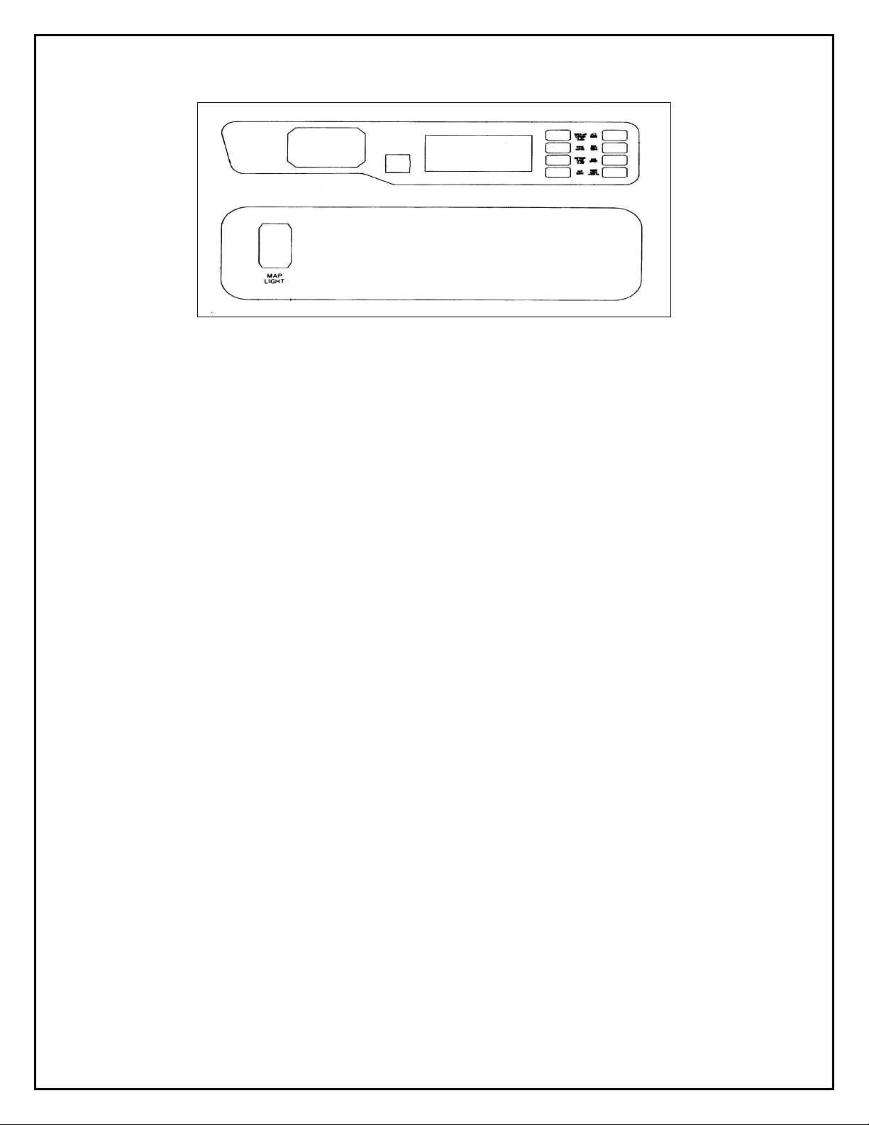
NOTE: Switches will vary according to options on vehicle.
AIRSTREAM DASH CONTROLS
Most automotive gauges and controls are standard instruments provided by the chassis manufacturer. Their
function and use is described in your Drivers Manual. The exception on automotive controls is the
heater/air conditioner. Operating- instructions on these components can be found in the chassis section of
this manual.
DASH SWITCHES:
• Aisle Lights -
lights that could be bothersome to a driver at night.
• Docking Lights RS -
are intended for use when parking in a campground at night.
• Air Dump Switch
Freightliner air suspension. There are two advantages to dumping the air, first it lowers the
vehicle and makes the first step height easier to use, and second, without air in the suspension
you may find it unnecessary to deploy the stabilizing/leveling jacks.
Armrest Switches
• ICC Blink -
commonly used as a way of indicati ng your thanks for a courtesy shown to you by another driver.
• Rear Camera -
bumper and operating the switch tilts the camera to view further back.
• Driving Lights -
• Defrost Fans -
switch turns them on and off and each fan has it's own switch to operate the oscillating feature.
• Door Lock -
Remember to hide an extra door key on the exterior in case of unexpected battery failure. The
manual knob is located by the passenger seat and is for interior use only.
• Auxiliary Start -
discharged to turn the engine over. To operate, hold the switch in the start position, and then use
the ignition switch in a normal fashion. Operating the auxiliary start switch closes the points on a
large solenoid, tying all three-vehicle batteries together for increased starting power.
The low aisle lights will allow passengers to converse without using overhead
The docking lights illuminate the area at the side of the motorhome and
– Down on the side of the armrest is a switch (valve) that is part of the
With this switch it is possible to blink the clearance lights on the motorhome. Ifs most
The rear view-monitoring camera has two positions. One will show the rear
To operate the driving lights the regular headlights must be turned on first.
In cool, damp weather these fans really help to clear the large windshields. This
The main door deadbolt can be locked or unlocked electronically from the drivers seat.
The auxiliary start switch is intended to be used if the engine battery becomes too
B-4

AIRSTREAM 360 XC LAND YACHT OWNERS MANUAL
• Generator Switch -
Generator without leaving the driver's seat. It should be noted a built-in time delay allows the
generator to reach full operating speed before 120 volt current is provided to the coach.
• Mirror
left mirror in the direction indicated. The paddle type switch marked heat is for defrosting the
mirrors. (Hopefully you won't need this unless you're a skier).
• Map Lights – Lights mounted above both cab seats to aid in reading. Switches are mounted
in both armrests.
POWER SEAT CONTROLS
Besides the normal power seat switch there are two additional finger levers. One allows the seat to recline
and the other will allow the seat to rotate.
WARNING: Never adjust drivers seat while vehicle is in motion.
CAUTION: Revolving the power seat completely around will pull the wiring apart. The seats should
only be swiveled toward the center of the vehicle. If the wires are loosened they can be reconnected
by following the color code: Red to red, green to green, etc. On so me models the wires will be on a
plug that can be reattached.
TRAILER TOWING AND DRIVING TIPS
Since this vehicle is designed and intended to be used primarily as a load carrying vehicle, towing a trailer
will affect handling, durability and economy. Maximum safety and satisfaction depends upon proper use of
correct equipment and avoiding overloads and other abusive operation.
- Move center switch to R or L. The four perimeter switches will then move the right or
The remote generator switch on the dash allows the driver to start or stop the
CAUTION: The maximum loaded trailer weight that you can pull with your vehicle is 5,000 lbs.
Vehicles should be properly equipped for towing trailers. Information on trailer hauling ca pabilities
and special equipment required may be obtained from your Airstream dealer.
CAUTION: The Gross Combination Weight Rating is the total allowable weight of the motorhome
combined with the weight of the vehicle or trailer being towed. Do not exceed this weight whenever
you are towing behind your motorhome. 31,350 lbs. is the GCWR.
To assist in attaining good handling of the vehicle/trailer combination it is important that the trailer tongue
load be maintained at approximately 10% of the loaded trailer weight, but not to exceed 500 lbs. Tongue
loads can be adjusted by proper distribution of the load in the trailer, and can be checked by weighing
separately the loaded traile r and then the tongue.
When towing trailers, tires should be inflated to the highest pressures shown on the information plate
attached to the driver’s doorjamb or dash of your motorhome. The allowable passenger and cargo load
(GVW) of thi s vehicle is reduc ed by an amount equal to the trailer t ongue load on the trailer bitch.
Trailer brakes are required on axles of trailers over 1,000 lbs. loaded weight,
CAUTION:
If your Freightliner chassis requires towing please refer to their manual for directions. They may be
called at 1-864-487-1700.
B-5

AIRSTREAM 360 XC LAND YACHT OWNERS MANUAL
NOTES
B-6

AIRSTREAM 360 XC LAND YACHT OWNERS MANUAL
CHASSIS
The Airstream motorhome is built on a Freightliner chassis. Operation of the engine and other related
components are discussed in the Freightliner Owners and Drivers Manual supplied with each coach.
If repairs are needed it can be difficult to determine which parts of the chassis are warranted by
Freightliner, and which are Airstream's responsibility. The following list shows the major components of
the chassis and the company responsible for their servicing.
FREIGHTLINER X LINE CHASSIS
Engine Air Conditioner Compressor
Transmission Shocks
Brakes Automotive Fuse Panels
Steering Assembly Parking Brake
Front Spindle, Bearings Fuel Tank
Alternator Cruise Control
Turn Signals Wheels
Drive Axle and Hubs
AIRSTREAM
Auxiliary Heater Windshield Wipers
Dash Air Conditioner/Heater Isolator
The above list covers almost all of the chassis components. If you need further clarification or information
your dealer should be contacted with the details.
ENGINE ACCESS
Although most engine functions and maintenance can be preformed from outside the coach, occasionally
"top" engine service will be required.
To make this servicing easier the bed top can be raised with the assistance of gas props. Once the bed top is
raised the engine cover can be unlatched and raised to expose the engine.
WARNING - The lifting and supporting strength of the gas props vary according to temperature.
Props that support the bed top when hot may let the bed close ra pidly when cold.
AIR BRAKE SYSTEM DRAINAGE
Your motorhome is equipped with an air brake system. When air is compressed some liquid is forced out
and collects in the bottom of the air ranks and must be drained.
Three drain valves are on your brake system. The valves can be opened for drainage by pulling on the
looped cables in your front wheel wells on each side. See your Freightliner operator’s manual under Pretrip Inspection for directions.
C-1
AIRSTREAM 360 XC LAND YACHT OWNERS MANUAL
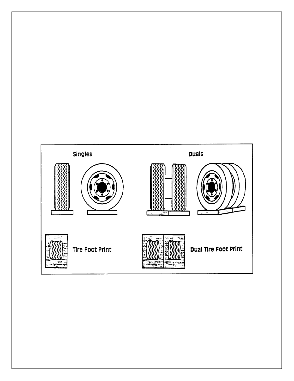
TIRE SUPPORT
Since motorhomes may sit for long periods of time it is important to properly support the tires if blocks are
used for level ing.
The Michelin Technical Group provides the following information.
Extreme caution must be taken to ensure that the tires are fully supported when using blocks to level
motorhomes and/or RV's. The load on the tire should be evenly distributed on the block and in the case of
duals, evenly distributed on blocks for both tires. If not property done, the steel cables in the sidewall of the
tires may be damaged and could lead to premature fatigue of the sidewall.
The
CORRECT
longer than the tire's footprint. This provides maximum support to the tires and assures that the load is
evenly distributed throughout the tire's footprint are a.
methods are shown in Figure 1. Please note that the blocks are wider than the tread and
FIGURE I
CORRECT
C-2
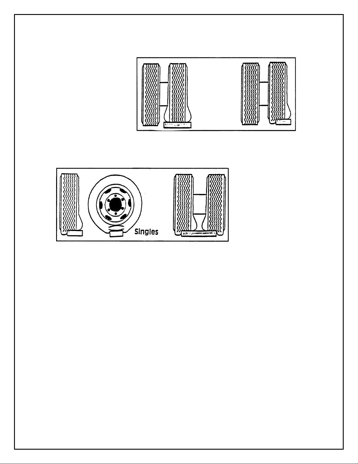
AIRSTREAM 360 XC LAND YACHT OWNERS MANUAL
INCORRECT
One tire or a portion of one
tire is supporting the full
load.
Portion of two tires are
supporting the full load.
CAUTION:
casing failure resulting in serious injury or property damage. If, on previous occasions, the tires
have been incorrectly supported, a hidden damage may be present. Please contact your local
Michelin dealer and request an inspection and a determination of possible damage.
Tires incorrectly supported, as shown above, may be damaged which could lead to
C-3

AIRSTREAM 360 XC LAND YACHT OWNERS MANUAL
Engine Block Heater
A switch is located in the bedroom for the engine block heater. It is inside the roadsidehanging wardrobe above the lower shelf, accessed from the side.
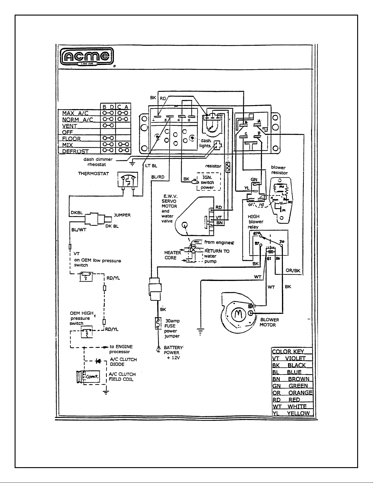
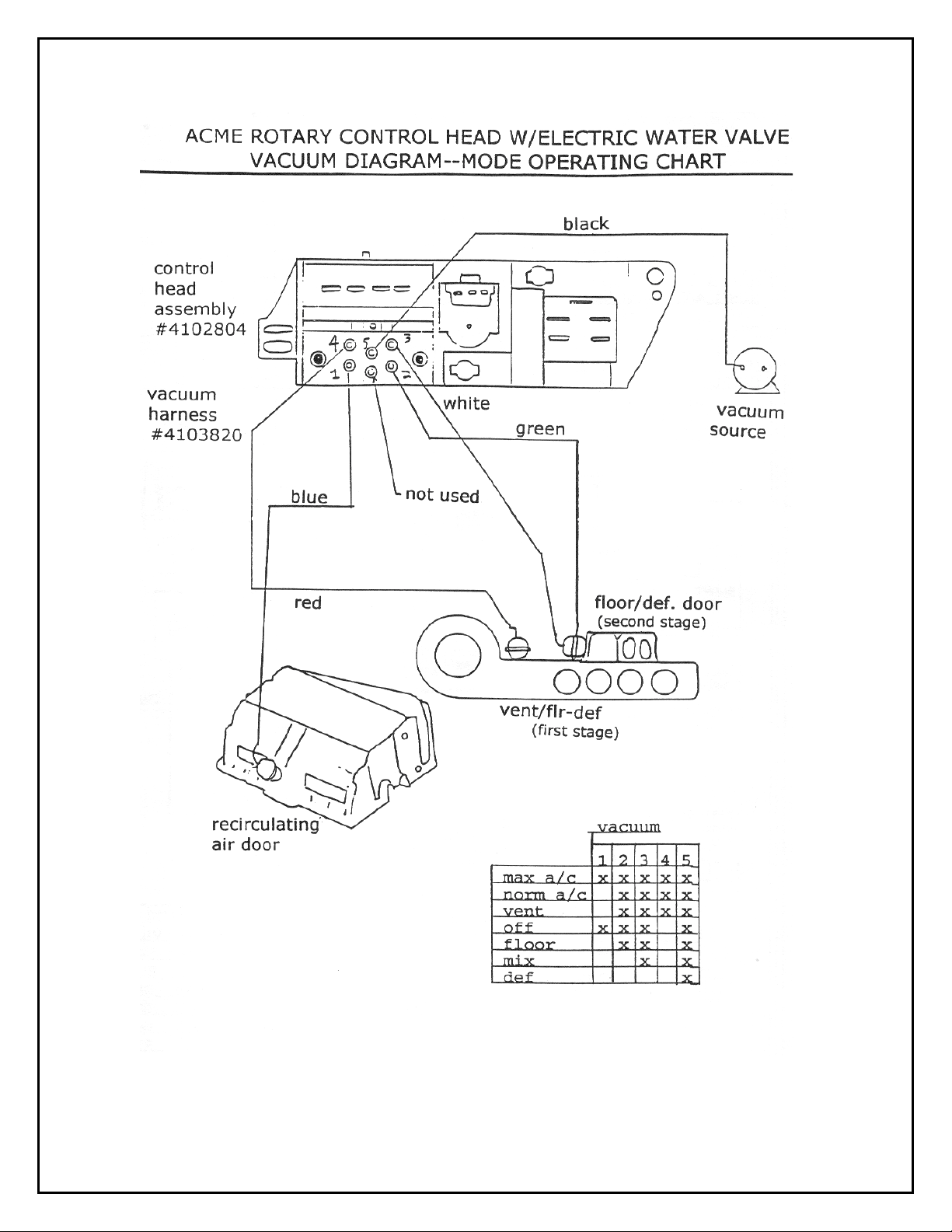
DASH AIR CONDITIONER/HEATER
Acme Radiator Air Conditioning, Inc.
17103 St. Rd. 4E
Goshen, Indiana 46526
800-552-2263
OPERATION
The dash heater control is very similar to many automobiles
The center rotary switch marked "cold-hot" controls the amount of hot water flowing through the
heater core. When the maximum air conditioner is engaged, inside air is circulated through the
evaporator to obtain the utmost in cooling. The two positions marked vent and norm draw outside
air through the evaporator.
SERVICE
Acme has requested you to call them on the 800 number listed above should you experience any
service problems. They are usually able to help get any repairs needed at an air conditioner repair
facility close to your location.
The following pages include wiring diagrams and vacuum line diagrams.
C-4
AIRSTREAM 360 XC LAND YACHT OWNERS MANUAL
C-5
AIRSTREAM 360 XC LAND YACHT OWNERS MANUAL
C-6

AIRSTREAM 360 XC LAND YACHT OWNERS MANUAL
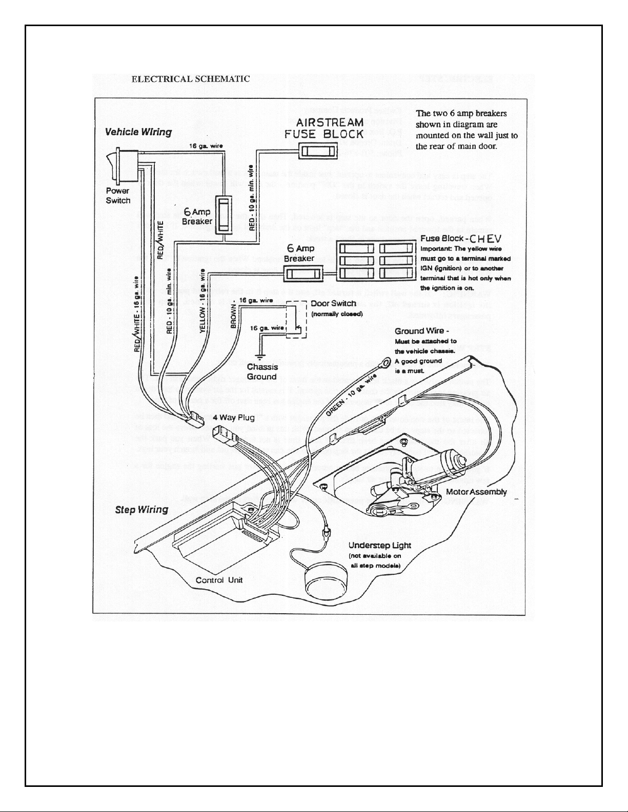
ELECTRIC STEP
Manufacturer:
Kwikee Products Company
Division of Ashton Corporation
P.O. Box 638
Drain, Oregon 97435
Phone: 503-836-2126
The step is easy and convenient to operate. Just inside the main door is a wall switch for the step.
When traveling, leave the switch in the "ON" position - the step will lower when the door is
opened and retract when the door is closed.
When parked, open the door so the step is lowered, then shut the switch off. The step will remain
in the lowered position and the "step" light on the dash will be extinguished. If left on it will run
your engine battery down in about a week.
If you forget and leave the switch off as you leave - No Problem! When the ignition is "ON" the
wall switch is by-passed and the step will retract when the door is closed.
WARNING: If the wall switch is turned off, and the step is in the retracted position when
the ignition is turned off, the step will not lower when the door is opened. Keep your
passengers informed.
STEP WELL COVER
Your motorhome is equipped with a pneumatically powered step well cover.
The switch (valve) is a black lever located in the front of the passenger right hand arm rest. The
air pressure is supplied by the chassis air ride system. It is normal for the air system to leak down
so you may find the cover to be inoperable if the engine has been shut off for a period of time.
The intent of the step cover is to provide the passenger with a "floor" while traveling and then be
retracted so the steps can be used when stopped. With this in mind you can see where the loss of
air after the motorhome has been shut off for a time is not a problem. When you park the
motorhome you'll normally retract the step cover so you can at least get out and stretch your legs.
If you happen to lose air pressure before retracting the step cover just starting the eng ine for a few
minutes will replenish the air supply.
WARNING: Do not operate the pneumatic cover while standing in the step well.
C-7
AIRSTREAM 360 XC LAND YACHT OWNERS MANUAL
C-8

AIRSTREAM 360 XC LAND YACHT OWNERS MANUAL
OPERATING INSTRUCTIONS
For control units #9514 and #9591
1. After the installation is complete and with the entrance door open, turn the power switch on.
2. Close the door. The step should retract and lock in the up position.
3. Open the door. The step should extend and lock in the down position with the understep light
NOTE
on.
4. Turn the power switch off. The step should remain in the extended position with the understep
light off when the door is closed. The procedure can also hold the step in the retracted position.
With the power switch off, the step extended, and the entrance door closed, turn on the vehicle
5.
ignition. The ignition safety system will go into effect and the step will automatically retract.
NOTE
ignition safety system is inoperative and the step will remain in the extended position.
vehicle is driven with the step in the extended position there is the possibility of causing major
damage to both the step and the vehicle.
retract.
WARNING:
DO NOT OPEN THE DOOR until the step completely retracts. If the door is opened before the
step completely retracts and locks in the up position, the step will stop moving. The step may only
be partially extended. Stepping on a partially extended step may cause damage to the step frame
and/or motor assembly. When the door is closed the step will finish retracting.
The under step light is not available on all step models.
-
-
If the yellow wire was not connected in Step #11 of the HOOKUP PROCEDURE the
If the
The power switch must be turned on for the step to
When the ignition safety system goes into effect and the step automatically retracts,
WARNING:
extend as soon as the ignition is turned off, even if the power switch is off. If the step is not
allowed to extend fully and lock out before the door is closed, the step will stop moving. The step
may only be partially extended. Stepping on a partially extended step may cause damage to the
step frame and/or motor assembly. If the door remains closed, the step will retract if either the
ignition or power switch is turned on. If the door is reopened the power switch must be turned on
for the step to finish extending.
WARNING:
has been turned off and the door is opened. The power switch must be turned on in order to
operate the step. To determine if your unit has the "Last out" feature follow these procedures:
With the ignition switch on, the door closed, the power switch off, and the step retracted, turn off
the ignition. Open the door. If the step extends, your unit is equipped with the "last out "feature.
If the entrance door is opened before the vehicle ignition is turned off, the step will
If your step does not have the 'Last out" feature, it will not extend once the ignition
Be Safe - Look Before You Leap!
C-9

AIRSTREAM 360 XC LAND YACHT OWNERS MANUAL
General Service Notes
If the power wire to the step is disconnected from its source and reconnected, a spark is common. This is
caused by the momentary charging of the control unit and does not necessarily indicate the system is
staying on, causing a drain on the battery.
If battery drain is suspected, observe the understep light (if so equipped) while the step is extending. The
power switch must be on for the understep light to operate. When the step locks into the down position, the
understep light should become noticeably brighter. If it does not, the control may not be shutting off. Turn
the power switch off and unplug the four way plug between the control unit and the vehicle to prevent
overheating the motor.
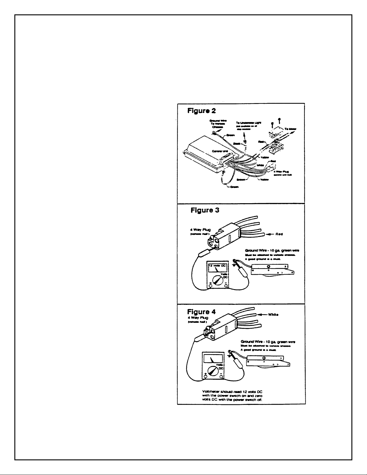
To further determine that the control is not shutting off, remove the two (2) screws from the connector on
the motor leads between the motor and control unit. Remove the seal assembly. (See Figure 2 on page #8)
Place a voltmeter between the red and yellow motor leads than reconnect the four way plug. Turn the
power switch on. If any voltage is read, the control is not shutting off and may be defective. When doing
this test, switch the voltmeter leads back and forth between the red and yellow motor leads to be sure no
voltage shows. If any voltage shows, disconnect the four way plug to keep the motor from overheating. If
zero voltage is present, the control has shut off and is normal.
If the step does not work or operates erratically, such as extending part way and shutting off, the first item
that should be checked is the vehicle battery. The voltage across the battery terminals should be at least
12.7 volts DC to insure a well charmed battery. A battery that reads below 12.7 volts DC may drop as low
as 8 volts DC when a load is drawn, such as the engaging of the step motor. The control unit will shut off if
the loaded voltage falls below 9 volts DC. The control unit will remember which function it was
performing. It will wait between two and five seconds (time depends upon temperature) and will try again
to complete the original function. If the supply voltage is still below 9 volts, the control will go into another
delay state. If the supply voltage remains above 9 volts DC, the original function will be completed. Should
the supply voltage again fall below 9 volts the system will go into another delay state. It many take a couple
of minutes to complete the original function. Low supply voltage may cause erratic operation of the step.
Intermittent ground may also cause erratic operation of the step.
The step may also operate erratically if the step is being operated directly from a converter and the output
from the converter is not adequate or properly filtered for clean DC voltage. The converter must be capable
of producing a minimum of 30 amps for proper step operation.
If the control unit is hooked up electrically backwards, the step will not operate. If ground to the control
unit is lost, either between the step control unit and the vehicle chassis (the 31 " long 10 gauge green
ground wire), or between the vehicle battery and ground (negative battery cable) the step will not function.
Make sure the battery terminals and all wire connections are clean and tight.
Be sure all wires are of proper gauges or heavier as specified in the wiring diagram.
WARNING: IMPORTANT: No other devices (hearers, fans, burglar alarms, lights, etc.) can be
incorporated in the same circuit as the control unit or step. This may cause the step or control unit to
malfunction and may void the warranty.
Check the step for physical damage. If the step has been struck by some kind of road hazard, the step
mechanism may be bent, causing the step to bind. Check the tread, sliding rails, and extending arms for
physical damage. Also check the pivot points for rusting. (See the LUBRICATION AND
MAINTENANCE SCHEDULE).
If the power switch is on and the step will not extend when the door is opened and/or retract when the door
is closed, but there is a cli cking noise coming from the control unit (the engaging and disenga gi ng of the
relays in the control unit) the first item that should be checked is the motor.
C-10
AIRSTREAM 360 XC LAND YACHT OWNERS MANUAL
See the MOTOR TEST PROCEDURE. The relays will engage and disengage (the clicking noise) when the
door switch is cycled if the motor is malfunctioning.
These general service notes and the following test procedures cover the most common problems associated
with Kwikee electric steps. Due to the number of variable conditions available, you may experience
symptoms other than those covered. Please feel free to contact the customer service department at 1-800736-9961 for further information or assistance.
TEST PROCEDURE - VEHICLE
WIRING:
Read the General Service Notes before
starting any test procedure.
Unplug the four way plug between the
1.
control unit and the vehicle wiring. (See Figure
2)
2. TO CHECK THE MAIN PO WER
SOURCE:
RED wire from the vehicle half of the four way
plug and the ring terminal on the end of the 10
ga. green ground wire from the contr ol unit to
the vehicle chassis (See Figure 3).
Steps manufactured before August 26, 1991
used a braided ground cable to ground the step
to the vehicle chassis. The control unit on steps
manufactured after that date are grounded
directly to the vehicle chassis by the 10 ga .
green ground wire as shown in Figure 2. If the
step is equipped with a braided ground cable,
substitute the braided ground cable in place of
the green ground wire in these test procedures
The reading should be about 12 volts DC. If
the voltage is low there may be a loose or
corroded connection, or low battery charge. If
the voltage reading is zero, check the 25 or 30
amp fuse/circuit breaker and all connections.
Be sure there is a good -round connection
between the step frame and the vehicle chassis.
See Step #2 of the HOOKUP PROCEDURE.
A good ground connection is a must. If the
reading is approximately 12 volts DC proceed
with the next test.
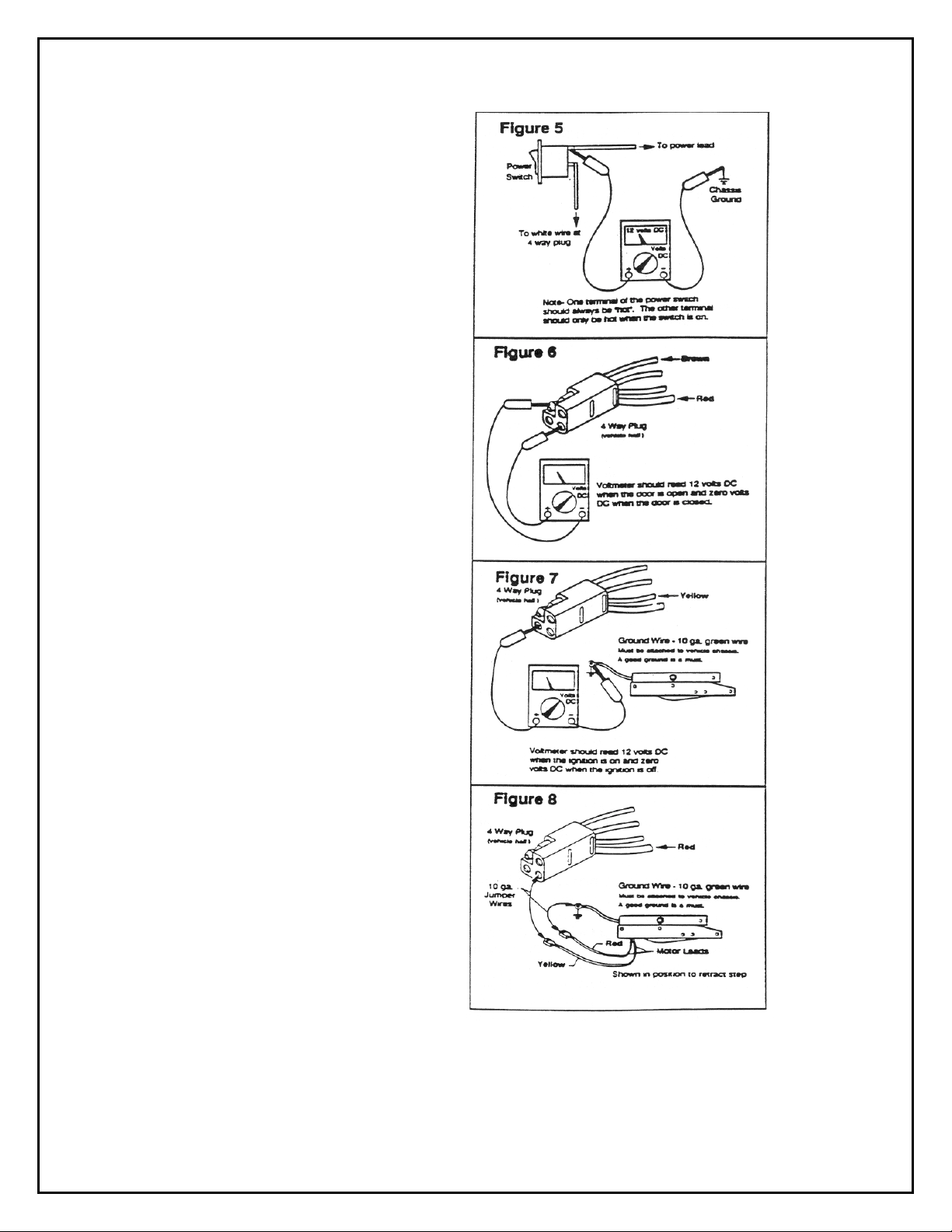
TO CHECK THE POWER SWITCH:
3.
Connect the voltmeter between the WHITE
wire from the vehicle half of the four way plug
and the ring terminal on the green ground wire.
(See Figure 4) The reading should be about 12
volts DC with the power switch on and zero
when the switch is off. If the voltmeter reads
zero with the power switch on, the first item to
check is the inline fuse or circuit breaker in the wire between the power switch and the power lead (red
wire). If the fuse/circuit breaker is all right, connect the voltmeter between the terminals on the power
switch with the wire leading to the power wire (red wire) and the ground. (See Figure 5)
Connect a voltmeter between the
NOTE -
.
C-11
AIRSTREAM 360 XC LAND YACHT OWNERS MANUAL
If the reading is still zero check the wire
leading to the power lead for a loose
connection or cut wire. If the reading is about
12 volts DC, turn on the power switch and
check the other power switch terminal in the
same manner, by connecting the voltmeter
between the terminal and ground. If the
reading is zero, replace the power switch. If
the reading was about 12 volts DC, there
may be a loose connection or cut wire
between the power switch and the vehicle
half of the four way plug.
4.
TO CHECK THE DOOR SWITCH:
Connect the voltmeter between the RED wire
from the vehicle half of the four-way plug
and the BROWN wire in the same plug (See
Figure 6). The reading should be about 12
volts DC when the door is open and zero
when the door is closed. If the reading is zero
with the door open, check the ground
connection from the door switch. This
connection should be clean and tight. See
Step #8 of the HOOKUP PROCEDURE. An
improper ground can cause intermittent or
erratic operation of the step. If the step will
not retract after being extended or extends
with the door closed, the BROWN wire to
the door switch may be touching a grounded
surface inside the wall behind the doorjamb,
or the door switch terminals may be touching
a grounded surface or each other. If the step
extends and retracts by its self while
traveling, check the conditions previously
described. With plunger door switches, be
sure that the door switch plunger is depressed
at least two thirds of its travel when the door
is closed. If the switch is not depressed at
least two thirds of its travel, it is possible for
the switch to make intermittent contact as the
vehicle frame shifts slightly while traveling
alone, the roadway. With magnetic door
switches, be sure the magnet is in place and
proper clearance is maintained between the
switch and magnet. If all the previous
conditions check okay, the door switch may
be faulty.
TO CHECK THE IGNITION SAFETY SYSTEM: Connect the voltmeter between the YELLOW wire
5.
from the vehicle half of the four way plug and the ring terminal on the green ground wire (See Figure 7).
The reading should be about 12 volts DC when
C-12
Loading...