

Page 1
INSTALLATION INSTRUCTIONSOWNER’S GUIDE &
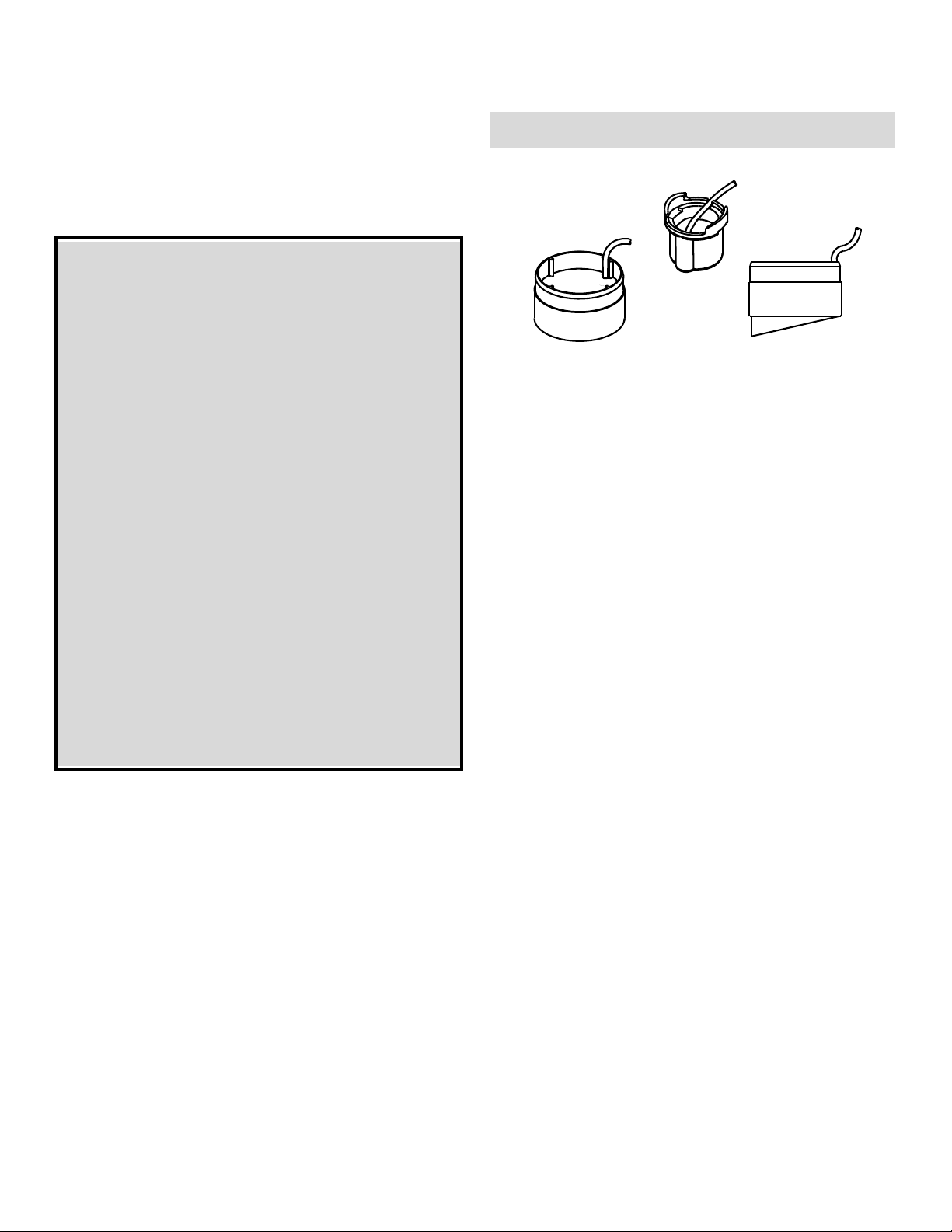
In-Hull & Trolling Motor
Puck Transducer
Models: P72, P76, P78
Follow the precautions below for optimal
product performance and to reduce the risk of
property damage, personal injury, and/or death.
WARNING: Always wear safety goggles and a dust
mask when installing.
17-010 rev.11 09/21/12
CAUTION: Chose the transducer designed for your
boat’s deadrise angle. Never use adhesive to fill gaps
between the transducer and the hull since this will
greatly reduce the transducer’s performance.
CAUTION: The fiberglass hull below the transducer
must be SOLID. The transducer will not transmit
through coring material such as foam or balsa wood.
CAUTION: Never pull, carry, or hold the transducer by
the cable. This may sever internal connections.
Record the information found on the cable tag for future reference.
Part No._________________Date___________Frequency________kHz
P72
P78
P76
Applications
• Fiberglass hulls only
• Recommended for high-speed boats
• P72 and P76 accommodate a deadrise angle of 10
• P78 accommodates a deadrise angle of 10° – 22°
° or less
CAUTION: Never use solvents. Paint, sealants,
cleaners, fuel, and other products may contain
solvents that can damage plastic parts, especially
connectors.
IMPORTANT: Please read the instructions completely
before proceeding with the installation. These
instructions supersede any other instructions in your
instrument manual if they differ.
In-Hull Mount
Tools & Materials
Safety goggles
Dust mask
Duct tape
Pole
Detergent (some installations)
Weak solvent (such as alcohol)
Disk sander (some installations)
Thin sealable plastic bag (some installations)
Cable ties
®
Water-based lubricant (such as K-Y
Grommet(s) (some installations)
Installation in a cored fiberglass hull:
Electric drill
Hole saw 78 mm or 3"
Miniature disk sander (such as Dremel Moto-Tool)
Casting epoxy (such as Polypoxy #7035/7040 by Pettit)
Paper cup
Stirrer
jelly) (some installations)
Mounting Location
About Fiberglass Hulls
Since the hull absorbs acoustic energy, transmitting through the
hull reduces the transducer’s performance. Fiberglass hulls are
often cored in places for added strength or to reduce weight. These
cored areas contain balsa wood or structural foam which are poor
sound conductors. Do not locate the transducer over coring.
Placement
CAUTION: Do not mount the transducer near water intake or
discharge openings or behind strakes, fittings, or hull irregularities
that will disturb the water flow.
Choose a location:
• Where the fiberglass is SOLID (no air bubbles are trapped in
the fiberglass resin) and where no coring, flotation material, or
dead air space is sandwiched between the inside skin and outer
skin of the hull.
• Where the hull below the transducer will be in contact with the
water at all times.
• Where the water flowing under the hull is smoothest with a
minimum of bubbles and turbulence (especially at high speeds).
• Away from interference caused by power and radiation sources
such as: the propeller(s) and shaft(s), other machinery, other
echosounders, and other cables. The lower the noise level, the
higher the echosounder gain setting that can be used.
• Where the transducer beam will not be blocked by the keel or
propeller shaft(s).
• Where there is adequate space inside the vessel for
installation.
Page 2
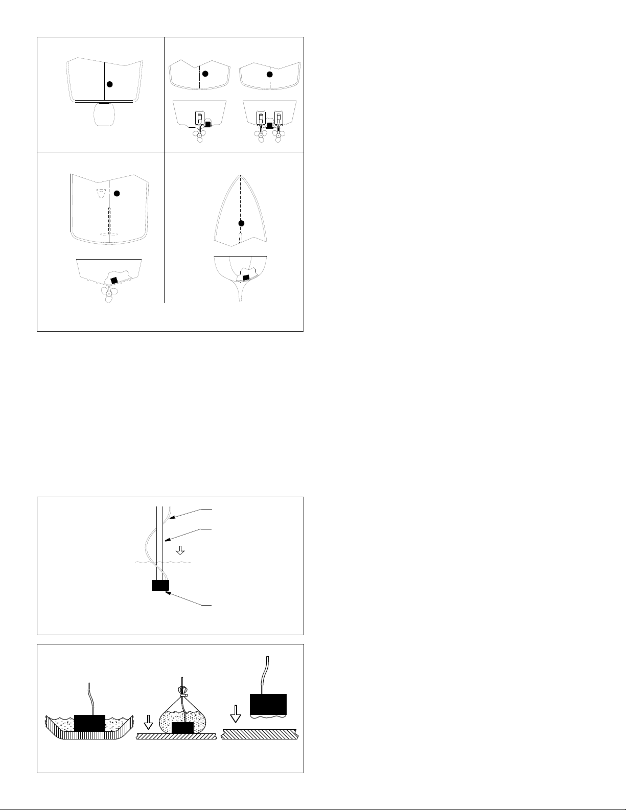
Outboard Inboard/outboard
Inboard Sailboat
Figure 1. Selecting the mounting location
Copyright © 2005 Airmar Technol ogy Corp.
Boat Type (see Figure 1)
Consult the boat manufacturer for the best transducer placement.
If this information is unavailable, follow the guidelines below.
When possible, mount on the side of the hull where the propeller
blades are moving downward.
• Outboard powerboats—Install as far aft as is practical.
• Inboard/outboard powerboats—Install close to the engine(s).
• Inboard powerboats—Install forward of the propeller(s) and
shaft(s).
• Sailboats—Install on or near the centerline and forward of any
fin keel 300 - 600mm (1 - 2').
cable
pole
active face
Figure 2. Establishing a performance baseline
Copyright © 2005 Airmar Technology Cor p.
ABC
Testing the Selected Mounting Location
Establishing a Performance Baseline
The results of this test are used as a basis of comparison to
determine the best in-hull location for the transducer.
1. Take the boat to the maximum depth in which you will be
operating the echosounder. If deep water is not available, find a
location with at least 15m (50').
2. Connect the transducer to the echosounder.
3. Tape the transducer to a pole, cable side up. Do not tape over
the active face. Hold the transducer over the side of the boat
with the active face fully submerged and parallel to the water
surface (see Figure 2).
4. Observe the echosounder’s performance and the gain setting
required to obtain a reading on the display. Record the depth
reading.
Testing the Location
While the boat is at the same site (depth of water), test the
transducer inside the hull at the mounting location. Use one of the
test methods below.
A.For a location near the stern and a minimal deadrise angle—
Clean away any build-up of grease and/or dirt with detergent or
alcohol. Place the transducer against the hull and allow bilge
water to cover the surface where they touch (see Figure 3A).
B.For a greater deadrise angle—If the hull surface is not smooth,
grind it with a disc sander. Place the transducer inside a thin
plastic bag. Partially fill the bag with water and close it tightly with
a cable tie. Wet the surface of the hull and press the active face
of the transducer against it through the bag (see Figure 3B).
C.For any location—If the hull surface is not smooth, grind it with
a disc sander. Coat the face of the transducer with a water-
based lubricant (such as K-Y® jelly). With a twisting motion,
press the face against the hull (see Figure 3C) After testing,
wipe all traces of the lubricant from the transducer’s face.
Observe the echosounder’s performance and compare it to the
baseline. Look for a stable depth reading that is similar to the
baseline. Compare the thickness and intensity of the bottom trace.
If the performance is close to the baseline, this is a good mounting
location. Remember, energy is lost transmitting through the hull. If
the test reading differs markedly from the baseline, you will need
to find another location to install the transducer.
NOTE: If there is no reading or it is erratic, the transducer may be
positioned over coring that is absorbing the acoustic energy.
Choose another location. If no other spot is available, check with
the boat manufacturer to be certain coring is present before
proceeding with the instructions for “Installation in a Cored
Fiberglass Hull” on page 4.
Selecting the Adhesive
CAUTION: Do not use:
• “5 minute” epoxies because they are too brittle.
• RTV (silicone) adhesives because they absorb most of the
sound energy.
A hard adhesive, like the epoxy supplied, transmits sound best.
However, winter temperature extremes and flexing on trailer
rollers can cause it to delaminate. Soft adhesives absorb sound
and will greatly reduce performance. To compromise, use a
viscous slow-cure epoxy or a fairly rigid one-part adhesive
Figure 3. Testing at the selected location
Copyright © 2005 Airmar Technology Cor p.
sealant. In cold climates, a one-part polyurethane adhesive, such
®
as Boat-Life’s Life Seal
, may be best.
2
Page 3

Installation
Cored fiberglass hull—Follow separate instructions on page 4.
CAUTION: Do not proceed if the hull temperature is below 15°C
(60
°F) because the cure time of the epoxy will be greatly extended.
CAUTION: Do not use adhesive to fill gaps between the
transducer and the hull since this will greatly reduce the
transducer’s performance (see Figure 4).
1. The hull surface to be bonded must be flat, smooth, and free of
paint or any other finish. If the surface is rough, use a disk
sander to smooth an area 10cm (4") in diameter.
2. To ensure a tight bond, remove any dust, grease, or oil from the
hull surface and the bottom of the transducer with detergent or
alcohol. Dry both the selected area and the transducer.
3. If the hull temperature is above 15
until the color is uniform.
4. Apply the epoxy to the center of the transducer’s active face—
the flat side opposite the cable.
5. Press the transducer face onto the hull with a twisting motion to
expel all air bubbles. Do not use adhesive to fill gaps (see
Figure 4, 5, or 6). (If the hull is slanted, temporarily secure the
transducer in place with duct tape.) The adhesive is cured in 24
hours at 21
° C (70° F). The lower the temperature the longer the
cure time.
° C (60° F), mix the epoxy
P78 P76
NO
(or P72)
NO
Do not use adhesive
to fill gaps.
YES
Figure 4. Deadrise angle of 10° or less
Copyright © 2005 Airmar Technolog y Corp.
76 mm (3")
flat area
P78
YES NOYES
P76
(or P72)
angle too
steep
Figure 5. Deadrise angle from 10° –22° and flat centerline
Copyright © 2005 Airmar Technology Corp.
Cable Routing & Connecting
CAUTION: If the transducer came with a connector, do not
remove it to ease cable routing. If the cable must be cut and
spliced, use Airmar’s splash-proof Junction Box No. 33-035 and
follow the instructions supplied. Removing the water-proof
connector or cutting the cable, except when using a water-tight
junction box, will void the transducer warranty.
1. Route the cable to the echosounder being careful not to tear the
cable jacket when passing it through the bulkhead(s) and other
parts of the boat. Use grommet(s) to prevent chafing. To reduce
electrical interference, separate the transducer cable from other
electrical wiring and the engine(s). Coil any excess cable and
secure it in place with cable ties to prevent damage.
2. Refer to your echosounder owner’s manual to connect the
transducer to the instrument.
Installation in a Cored Fiberglass Hull
Installation in a cored hull is difficult. The objective is to bond the
transducer to the inside surface of the hull’s outer skin while
preventing any moisture from penetrating the core.
CAUTION: There is no way to determine if the outer skin is solid
(no trapped air bubbles in the fiberglass resin) at the selected
location before cutting the inner skin.
CAUTION: Do not proceed if the hull temperature is below 15
(60
° F) because the cure time of the epoxy will be greatly extended.
° C
P76P78
(or P72)
Do not use
adhesive to
NOYES
fill gaps.
Figure 6. Sailboat with fin keel & deadrise angle from 10° –22°
Copyright © 2005 Airmar Technology Corp.
2. Remove the plug of core material so the inner core of the hull is
fully exposed. Sand the inside surface of the outer skin using a
miniature disk sander (Dremel Moto-Tool). Slightly undercut the
surrounding coring if possible.
3. Clean and dry both the inside surface of the outer skin and the
face of the transducer with detergent or alcohol to remove any
dust, grease, or oil.
4. If the hull temperature is above 15
° C (60° F), mix the epoxy
until the color is uniform.
78mm (3")
pour in
casting
epoxy
inner skin
CAUTION: Do not use adhesive to fill gaps between the
transducer and the hull since this will greatly reduce the
transducer’s performance.
1. Using a 78 mm or 3" hole saw, cut through the inner skin and the
core at the selected location (see Figure 7). The core material
can be very soft. Apply only light pressure to the hole saw after
cutting through the inner skin to avoid accidentally cutting the
outer skin.
core
hull thickness
epoxy
outer skin
Figure 7. Installation in a cored fiberglass hull (P76 shown)
Copyright © 2005 Airmar Technology Corp.
3
Page 4

5. Pour the epoxy into the cavity to a depth of 6mm (1/4") and
immediately set the transducer in place with a firm twisting
motion to expel all air bubbles. Do not use adhesive to fill
gaps.
6. Mix a half cup of casting epoxy following the manufacturer’s
directions. Stir carefully to avoid trapping air in the mixture.
Pour this around the transducer until the cavity is full. Permit the
casting epoxy to set for at least 1 hour. If the cavity is at an
angle, as is usual, tape over the lower portion of the cavity. Mix
more epoxy and pour until the cavity is filled flush with the top of
the inner skin. If the transducer is covered with casting epoxy,
be sure the cable is bonded tightly so that no water seeps into
the core.
7. You may grind the surface smooth, if necessary, but do not
damage the cable.
8. If there is doubt as to the strength of the area, apply layers of
fiberglass overall to a satisfactory thickness. Be sure bilge
water cannot enter the core at the cable.
Trolling Motor Mount
Applications
• Electric trolling motor with diameter from 77–95mm (3–3-3/4")
• Can be adapted for use with smaller or larger motor cases
Tools & Materials
Safety goggles
Band clamp (some installations)
Cable ties
Location
Locate the transducer under the motor case (see Figure 8).
NOTE: If the motor has a strut that shades the transducer, it will
not significantly reduce the transducer’s performance.
Installation
Small motor case [64mm (2-1/2")]: Do not to over tighten the
band clamp causing the tabs on the transducer housing to break.
Large motor case [102mm (4")]: Purchase a larger stainless steel
band clamp in the plumbing supply section of most hardware stores.
1. Loosen the screw in the band clamp so that one end of the band
is free.
2. Wrap the band clamp around the motor case. Tighten the screw.
4. To prevent damage, coil any excess cable and secure it in
place with cable ties.
Maintenance & Repair
Keep the transducer free of marine growth and petroleum residue.
To clean use a soft cloth and mild household detergent.
Damaged Cable Jacket
1. Should the outer jacket of the cable be abraded or cut, check
that the internal conductors are not damaged.
2. If the conductors are damage free, allow the cable to dry and fill
the damaged area with sealant.
3. Cover the damaged area with electrical tape.
Severed Cable
1. Slide heat-shrink tubing onto the cable.
2. Splice each pair of matching colored conductors with rosin
core solder.
3. Wrap each conductor with insulating tape at the splice.
4. Splice the shield (braided) wire with solder.
5. Fill the spliced area in the cable with sealant.
6. Cover the damaged area with the heat-shrink tubing and follow
the manufacturer’s directions for its use.
NOTE: If the instrument fails to provide a reading, the problem
may not be the damaged cable; the transducer, connector or
instrument could be defective.
Transducer Replacement
The information needed to order a replacement Airmar transducer
is printed on the cable tag. Do not remove this tag. When ordering,
specify the part number, date, and frequency in kHz. For convenient reference, record this information at the top of page one.
Obtain parts from your instrument manufacturer or marine dealer.
Gemeco Tel: 803-693-0777
(USA) Fax: 803-693-0477
email: sales@gemeco.com
Airmar EMEA Tel: +33.(0)2.23.52.06.48
(Europe, Middle East, Africa) Fax: +33.(0)2.23.52.06.49
email: sales@airmar-emea.com
support tube
Routing the Cable
CAUTION: Do not put tension to the cable as it exits the
transducer, as excessive force can break internal connections.
CAUTION: On bow mounted motors, be sure the cable route does
not result in pinching the cable when the motor is in the UP position.
1. Route the cable around the side of the motor case and along the
support tube (see Figure 8).
2. Secure the cable to the support tube with cable ties.
3. Route the cable to the echosounder being careful not to tear the
cable jacket. To reduce electrical interference, separate the
transducer cable from other electrical wiring.
®
AIRMAR
TECHNOLOGY CORPORATION
4
35 Meadowbrook Drive, Milford, New Hampshire 03055-4613, USA
Copyright © 2004 - 2012 Airmar Technology Corp. All rights reserved.
cable
band clamp
transducer
Figure 8. Location and installation
Copyright © 1998 Airmar Technol ogy Corp.
www.airmar.com
cable ties
 Loading...