

Page 1
INSTALLATION INSTRUCTIONSOWNER’S GUIDE &
Transom Mount with Kick-up Bracket 20-035
Transducer or TRIDUCER® Multisensor
Model: P52
Follow the precautions below for optimal product
performance and to reduce the risk of property
damage, personal injury, and/or death.
WARNING: Always wear safety goggles and a dust
mask when installing
WARNING: When the boat is placed in the water,
immediately check for leaks around the screws and
17-002 rev. 04 04/12/11
any other holes drilled in the hull.
CAUTION:
impact only.
CAUTION: Never pull, carry, or hold the sensor by the
cable as this may sever internal connections.
CAUTION: Never strike the sensor.
CAUTION: Never use solvents. Cleaners, fuel, paint,
sealants, and other products may contain strong
solvents, such as acetone, which attack many plastics
greatly reducing their strength.
IMPORTANT: Please read the instructions completely
before proceeding with the installation. These
instructions supersede any other instructions in your
instrument manual if they differ.
Applications
• Not recommended for boat with large inboard engine(s).
• Good operation up to 40kn (46MPH).
Requires experimentation at higher speeds.
• Vertically orients the sound beam on hull with deadrise angle up
°
to 22
• Adjusts to transom angles up to 20°.
Tools & Materials
Safety goggles
Dust mask
Water-based antifouling paint (mandatory in salt water)
Screwdrivers
Adjustable wrench
Pencil
Electric drill
Drill bits and hole saw or spade bit:
Bracket holes 4mm, #23, or 9/64"
Fiberglass hull chamfer (preferred), 6mm, or 1/4"
Transom hole (optional) 20mm or 13/16"
Cable clamp holes
Masking tape
Marine sealant (suitable for below waterline)
Straight edge
Line (optional)
Zip-ties
The bracket protects the sensor from frontal
3mm or 1/8"
P52 TRIDUCER® Multisensor
Identifying Your Model
The model name is printed on the cable tag.
Antifouling Paint
Aquatic growth can accumulate rapidly on the sensor’s surface
reducing performance within weeks. Surfaces exposed to salt
water that do not interlock must be coated with antifouling paint.
Use water-based antifouling paint only. Never use ketone based
paint, since ketones can attack many types of plastic possibly
causing damage to the transducer. It may be easier to apply paint
before installing the sensor, but allow drying time. Reapply paint
every 6 months or at the beginning of each boating season.
Assembling
1. The bracket is shipped in the “up” (released) position. Before
attaching the sensor, set the bracket in the “down” (operating)
position by grasping the cross bar and pulling outward in an arc
(see Figure 1).
2. Run the cable through the bracket between the cross bar and
the transom (see photo on front page).
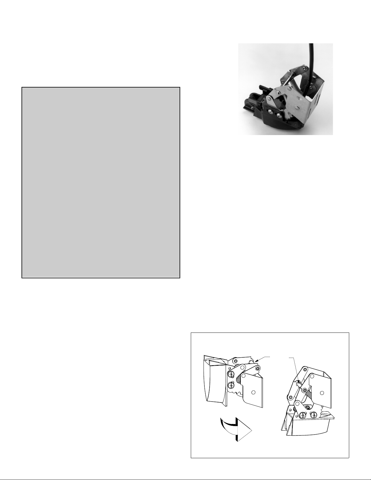
3. Attach the sensor to the bracket with the four #10-32 x 5/8"
machine screws, washers, and lock nuts. Tighten the screws so
the sensor remains in place, but can be adjusted (see Figure 2).
P52—Place the bracket inside the mounting tabs (see photo on
front page).
“up” (released) “down” (operating)
cross bar
Figure 1. Bracket positions (P37 shown)
Page 2
transom
lock nut (4)
flat washer (8)
mounting tabs
#10-32 x 5/8"
screw (4)
Figure 2. Transducer and bracket assembly (P37 shown)
Mounting Location
CAUTION: Do not mount in an area of turbulence or bubbles:
near water intake or discharge openings; behind strakes, struts,
fittings, or hull irregularities
CAUTION: Avoid mounting the sensor where the boat may be
supported during trailering, launching, hauling, or storage.
• For the best performance, the sensor must be in contact with
smooth water. To identify an area of clean water, observe the
water flow off the transom while the boat is underway.
• Allow headroom space above the bracket for it to release and
rotate the sensor upward (see Figure 3).
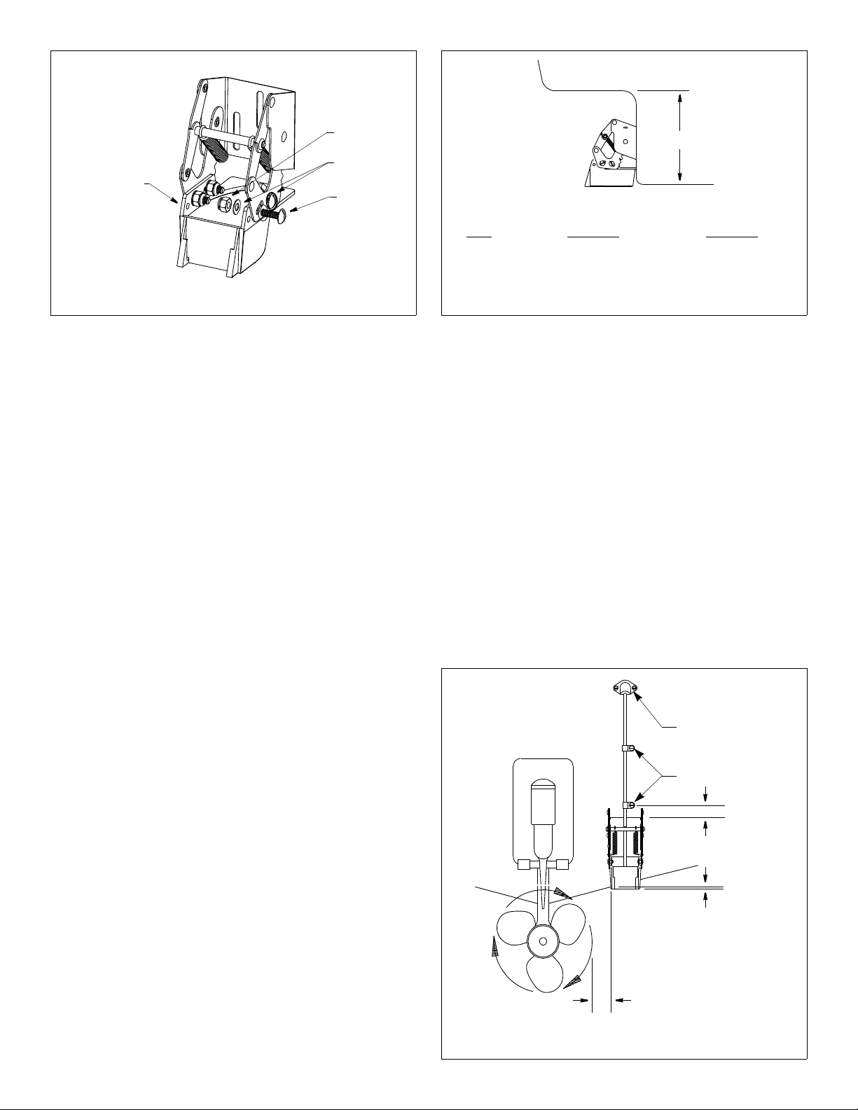
• Mount the sensor as close to the centerline (keel) of the boat as
possible to ensure the sensor remains in the water when the
boat is turning.
• Single drive boat—Mount at least 75mm (3") beyond the
swing radius of the propeller (see Figure 4). The starboard
side where the propeller blades are moving downward is
preferred.
• Twin drive boat—Mount the sensor between the drives.
height
Model
P52 175 mm (7-1/2") 215mm (9")
Height without Height with
paddlewheel paddlewheel
Figure 3. Height required at mounting location (P37 shown)
3. Using a 4mm, #23, or 9/64" bit, drill three holes 22 mm (7/8")
deep at the locations indicated.
4. Apply marine sealant to the threads of the three #10 x 3/4" selftapping screws to prevent water seepage into the transom.
Slide a flat washer onto each screw and fasten the assembly to
the hull. Do not tighten the screws completely at this time.
5. Using the vertical adjustment space on the bracket slots, slide
the sensor up or down to provide a projection of 6mm (1/4")
(see Figure 4). Tighten the screws.
6. Using a straight edge, adjust the angle of the transducer on the
bracket. Sight the underside of the transducer relative to the
underside of the hull (see Figure 6). Adjust the sensor on the
bracket so it is parallel to the bottom of the hull or at a slight
angle. For best results set the trailing edge of the transducer
1-3 mm (1/16 - 1/8") below the leading edge (see Figure 7).
Tighten the screws.
Installation
CAUTION: Do not position the leading edge of the sensor lower
than the trailing edge because aeration will occur.
CAUTION: Do not position the sensor deeper into the water than
necessary to avoid increasing drag, spray, and water noise and
reducing boat speed.
CAUTION: To prevent drilling too deeply, wrap masking tape
around the bit 22mm (7/8") from the point.
CAUTION: Fiberglass hull—Minimize surface cracking by
running the drill in reverse until the gelcoat is penetrated.
Mounting & Adjusting
1. Position the assembly at the selected location with the
transducer face parallel to the water. Good results can be
achieved on most boats when the bottom of the transducer is
about 6mm (1/4") below the bottom of the hull and parallel to the
waterline (see Figure 4).
2. With a pencil, mark the outline of the bracket slots on the hull.
Mark the screw location at the bottom of each slot to allow for
adjusting the bracket (see Figure 5).
2
cable cover
cable clamps
50mm (2")
Hull projections:
fiberglass, wood 6mm (1/4")
Bottom parallel to water line
75mm (3") minimum beyond
swing radius of propeller
Figure 4. Mounting location on single drive boat
Page 3

correct incorrect
(cannot adjust)
YES
YES
Figure 5. Mounting the bracket
Setting the Bracket Release Point
There is considerable force on the bracket during normal
operation. The amount of force is proportional to the drag which is
created by the:
• Sensor—shape, size, weight, and amount of projection
below the transom.
• Speed—the square of the speed of the boat.
A larger and heavier transducer or TRIDUCER
®
multisensor
creates more drag as does a higher boat speed. For example, the
drag at 40kn (46MPH) is 4 times that at 20kn (23 MPH).
Set the springs in the appropriate notches on the pivot arms (see
Figure 7).
• Middle or lower notches if the top speed of the boat is more
than 30kn (34MPH).
Release Line
CAUTION: Be sure that both ends of the line are well secured to
eliminate the possibility of becoming entangled in the propeller.
To facilitate raising the sensor to the “up” (released) position, a
line can be attached to the bracket’s crossbar (see Figures 7 and
1). An upward jerk on this line will release the bracket.
Cable Routing
CAUTION: Do not remove the connector to ease cable routing. If
the cable must be cut and spliced, use Airmar’s splash-proof
Junction Box No. 33-035 and follow the instructions provided.
Removing the waterproof connector or cutting the cable, except
when using a water-tight junction box, will void the sensor
warranty.
Route the sensor cable(s) over the transom, through a drain hole,
or through a new hole drilled in the transom above the waterline.
1. If a hole must be drilled, choose a location well above the
waterline. Check for obstructions such as trim tabs, pumps, or
wiring inside the hull. Mark the location with a pencil. Drill a hole
through the transom using a 20 mm or 13/16” hole saw or spade
bit (to accommodate the connector).
2. Route the cable(s) over or through the transom. Be sure the
cable is between the cross bar and the transom (see photo
on page 1).
3. On the outside of the hull secure the cable(s) against the
transom using the cable clamps. Position a cable clamp 50mm
(2") above the bracket and mark the screw hole with a pencil
(see Figure 4).
4. Position the second cable clamp halfway between the first
clamp and the cable hole. Mark this mounting hole. If there are
two cables, repeat this step.
5. If a hole has been drilled through the transom, open the
appropriate slot(s) in the cable cover (see Figure 8). The cable
cover can accommodate two cables when there are separate
parallel
NO
angle too severe
slight angle
NO
Figure 6. Transducer angle adjustment (P37 shown)
cables for depth and speed/temperature functions. Position the
cover over the cable(s) where it enters the hull. Mark the two
mounting holes.
6. At each of the marked locations, use a 3 mm or 1/8" bit to drill a
hole 10mm (3/8") deep.
7. Apply marine sealant to the threads of the #6 x 1/2" (13mm)
self-tapping screws to prevent water from seeping into the
transom. If a hole has been drilled through the transom, apply
marine sealant to the space around the cable leading through
the transom.
8. Position the two cable clamps and screw them in place. If used,
push the cable cover over the cable(s) and screw it in place.
9. Route the cable(s) to the instrument(s), being careful not to tear
the cable jacket when passing it through the bulkhead(s) and
other parts of the boat. To reduce electrical interference,
separate the sensor cable(s) from other electrical wiring and
sources of noise. Coil any excess cable and secure it in place
with zip-ties to prevent damage.
10.Refer to the echosounder owner’s manual(s) to connect the
sensor to the instrument(s).
cross bar
spring
pivot arm
1-3mm (1/16 -1/8")
stern
cable
notch
bow
Figure 7. Transducer angle & release point setting (P37 shown)
Figure 8. Cable cover
3
Page 4

Figure 9. 33-105
shear
pins (4)
shear pins (4)
Figure 10. 33-110
To improve performance, try the following one at a time in the
order given.
a. Increase the sensor’s angle in the water.
b. Move the sensor deeper into the water in increments of
3mm (1/8").
c. Move the sensor closer to the centerline of the boat.
Fill unused screw holes with marine sealant.
NOTE: High-speed operation [above 35kn (40MPH)] may
require less projection in the water to improve performance and
reduce the chance that water pressure will cause the bracket to
release.
Checking for Leaks
When the boat is placed in the water, immediately check for
leaks around the screws that fasten the sensor to the hull. Note
that very small leaks may not be readily observed. Do not leave
the boat in the water unchecked for more than three hours.
Testing on the Water
Bracket Release Point
CAUTION: Do not set the bracket to withstand more force than
the minimum required to hold the sensor in the "down" (operating)
position, since this increases the chance that the bracket will not
release when the sensor is struck.
The correct bracket release setting has been found when the
sensor remains in the “down” (operating) position under normal
operating conditions. Gradually increase the boat speed and
observe the echosounder. When the bracket releases, there will
be an instantaneous loss of echo. Depending on conditions, the
bracket may either partially release and reset itself or fully release
rotating the sensor through an arc of 105
If the bracket releases before reaching top boat speed, set the
springs in the next lower notches and reset the bracket in the
“down” (operating) position. Repeat the test until the desired
result is obtained.
Echosounder Performance
1. If there is a temperature sensor, allow a few minutes for it to
respond to a major temperature change from the air to the water.
Check for an accurate reading.
2. Become familiar with your echosounder’s performance at a
speed of 4kn (5MPH).
3. Gradually increase the boat speed and observe the gradual
decline in performance due to turbulent water flowing over the
transducer’s active surface.
4. If the decline in performance is sudden (not gradual), identify
the boat speed at which the onset occurred. Return the boat to
this speed, then gradually increase speed while making
moderate turns in both directions.
5. If the performance improves while turning to the side on which
the sensor is installed, the transducer’s position probably needs
adjustment. It is probably in aerated water.
°.
Maintenance, Repair, & Replacement
Speed Sensor
Be sure to place the bracket in the “up” (released) position before
beaching, trailering, or hauling the boat since these are the main
causes of speed sensor breakage.
Cleaning
Clean the transducer’s surface with a Scotch-Brite® scour pad
and mild household detergent taking care to avoid making
scratches. If the fouling is severe, lightly wet sand with fine grade
wet/dry paper.
If the paddlewheel becomes fouled or inoperable, unsnap the
paddlewheel assembly from the main housing for cleaning.
Severe cases may require removal of the paddlewheel. Using a
small screwdriver, remove the paddlewheel shaft retainers. (If a
retainer is lost, a dab of RTV caulk on the end of the shaft will
secure it.) If necessary, use a stiff brush or putty knife to remove
the growth being careful to avoid scratching the transducer’s face.
Wet sanding is permissible with fine grade wet/dry paper.
Sensor Replacement & Parts
The information needed to order a replacement sensor is printed
on the cable tag. Do not remove this tag. When ordering, specify
the part number, date, and frequency in kHz.
Replace broken or worn parts immediately. The speed sensor
shear pins are designed to fracture upon impact. The water
lubricated paddlewheel bearings have a life of up to 5 years on
low-speed boats [less than 10kn (11MPH)] and 2 years on highspeed vessels. For a replacement paddlewheel carrier without a
cable, order the Airmar Snap-in Paddlewheel Carrier 33-105 (see
Figure 9); for an assembly with a cable, order a Transom
Paddlewheel Kit 33-110 (see Figure 10) from your marine dealer
or echosounder manufacturer.
This stainless steel bracket interchanges with the Plastic Release
Bracket 20-039 using the same mounting holes.
Obtain parts from your instrument manufacturer or marine dealer.
Gemeco Tel: 803-693-0777
(USA) Fax: 803-693-0477
email: sales@gemeco.com
Airmar EMEA Tel: +33.(0)2.23.52.06.48
(Europe, Middle East, Africa) Fax: +33.(0)2.23.52.06.49
email: sales@airmar-emea.com
®
AIRMAR
TECHNOLOGY CORPORATION
35 Meadowbrook Drive, Milford, New Hampshire 03055-4613, USA
www.airmar.com
Copyright © 1995 2011 Airmar Technology Corp. All rights reserved.
4
 Loading...