

Page 1

17-472-01 rev.05 05/21/14
Owner’s Guide & Installation Instructions
Heading Sensor
Models: H2183
U.S. Patent No. 8,326,561
UK Patent No. 2 460 158
Record the serial number found on the underside of the sensor.
Serial No.____________ Date of Purchase______________
1
Page 2

All Rights Reserved. Except as expressly provided herein, no part of this manual may be
Copyright © 2008 - 2014 Airmar Technology Corp. All rights reserved.
reproduced, copied, transmitted, disseminated, downloaded, or stored in any storage
medium, for any purpose without prior written consent of Airmar. Airmar hereby grants
permission to download a single copy of this manual and of any revision of this manual onto
a hard drive or other electronic storage medium to be viewed and to print one copy of this
manual or any revision hereto, provided that such electronic or printed copy of this manual
or revision must contain the complete text of this copyright notice and provided further that
any unauthorized commercial distribution of this manual or any revision hereto is strictly
prohibited.
Information in this manual is subject to change without notice. Airmar reserves the right to
change or improve its products and to make changes in the content without obligation to
notify any person or organization of such changes. Visit the Airmar website at
www.airmar.com for current updates and supplemental information concerning the use and
operation of this and other Airmar products.
2
Page 3

Table of Contents
Introduction.............................................................................. 4
Safety Instructions.................................................................... 5
Hardware, Tools & Materials................................................... 6
Where to Purchase Parts............................................................6
Choosing the Mounting Location............................................. 7
Installing................................................................................... 8
Mounting on a Vertical Surface................................................ 8
Flush Mounting on a Horizontal Surface..................................11
Cable Routing & Connecting....................................................12
Connecting to an NMEA 0183 Display.................................... 12
Connecting to an NMEA 2000® Network............................... 14
Calibrating the Compass........................................................... 15
Maintenance..............................................................................16
Troubleshooting........................................................................ 16
Firmware Revisions...................................................................16
NMEA 2000®: Load Equivalency Number..............................16
Trademarks................................................................................16
3
Page 4
Introduction
IMPORTANT: Please read the Owner’s
Guide completely before proceeding.
Thank you for purchasing an Airmar solid-state sensor. The compact housing is
waterproof with a single removable cable. The H2183 is actually three sensors in
a single unit—a three-axis magnetic compass, a three-axis accelerometer, and a
three-axis rate gyro. Data is simultaneously output in digital NMEA 0183 and
NMEA 2000° formats.
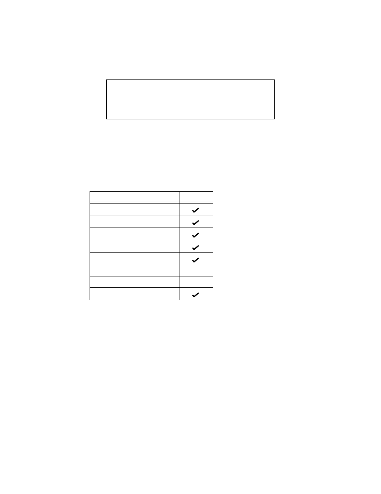
Functions & Outputs H2183
Magnetic compass heading
Heading relative to true north
Rate of Turn
Angle of pitch and roll
Rate of pitch & roll
NMEA 0183: RS422 Optional
NMEA 0183: RS232 Optional
NMEA 20000®; CAN
1. Only available if magnetic variation is available from an external device such as a GPS.
1
Features
• Fast response time
• Stable and accurate data in dynamic conditions
• Can be programmed to compensate for an installation that is not aligned to the
front of the vehicle/bow of the boat and / or level
• Can be calibrated to compensate for magnetic deviation caused by ferrous
metals and other electro-magnetic fields
• Waterproof housing
• Waterproof cable system
• Bracket or flush mount
4
Page 5

Follow the safety precautions below to reduce the risk of poor product
WARNING
Navigation Aid Only—The sensor is only an aid to
navigation and should never be solely relied upon. It is not a
replacement for traditional navigation aids and techniques,
and human judgement. Only official government nautical
charts contain all the information needed for safe navigation.
performance, property damage, personal injury, and/or death.
WARNING: Correct Installation Important
The sensor must be installed and operated according to the instructions in this
owner’s guide.
WARNING: Installation Safety
Always wear safety goggles and a dust mask when installing.
WARNING: Steel Vehicle/Boat
Do not install the sensor within a steel vehicle/boat because it is a ferrous
(magnetic) material. Instead, use Airmar’s model GH2183, combination GPS and
compass that can be mounted above the vehicle/boat.
WARNING: Compass Safe Distance
The sensor must be a minimum of 0.3m (1') from other standard and steering
compasses.
WARNING: Do Not Install Near Artificial Magnetic Field
Observe a safe distance from ferrous metals and anything that can create a
magnetic field to prevent interference to the magnetic compass.
WARNING: Electrical Safety
The power supply must be OFF before making electrical connections.
WARNING: Voltage
The power supply voltage must be 9 - 40 VDC.
WARNING: Fuse or Circuit Breaker
A safe installation requires a 0.5 amp fast-blow fuse or circuit breaker.
WARNING: Battery
Make power connections to a power source that is isolated from the engine start
battery(s). Voltage drops may cause the sensor to lose information and / or change
operating mode.
WARNING: Calibrating the Compass
The internal compass may need to be calibrated after the sensor is installed.
Perform the pretest to determine if calibration is necessary.
5
Page 6

Cables & Connecting/Converting Hardware
The Heading Sensor can be connected in several ways. You must have the
correct cable and any needed hardware before beginning the installation.
Sensor Cables Length Part No.
• NMEA 0183 Cable 10m 33-862-02
• NMEA 2000® Cable 6m 33-1029-02
• NMEA 2000® Cable 10m 33-1104-01
NOTE: Additional cable lengths are available.
Connecting/Converting Hardware Length Part No.
• NMEA 0183 to USB, Data Converter 33-801-01
• NMEA 0183 to USB Combiner NDC-4-AIR
• NMEA 2000® CAN to USB, U200 Gateway 33-727-01
• NMEA 0183 & NMEA 2000® Splitter 15m 33-632-01
• NMEA 0183 & NMEA 2000® Splitter 30m 33-632-02
Tools & Materials
Safety goggles
Dust mask
Torpedo level
Pencil
Electric drill
Drill bits and hole saws:
Pilot hole 3 mm or 1/8"
Bracket screw holes 4mm, #23, or 9/64"
Flush mount stud holes 6mm or 1/4"
Flush mount cable hole 38mm or 1-1/2"
Phillips screwdrivers
Marine sealant (aluminum hull)
Loctite® 242® or other removable thread locker (Flush Mount installation)
Deck gland (some installations)
Grommets (some installations)
Cutting pliers (some installations)
Heat-shrink tubing (some installations)
Heat gun (some installations)
Wire strippers (some installations)
Multimeter (some installations)
Cable ties (some installations)
Where to Purchase Parts
Lost, broken, or worn parts should be replaced immediately. Obtain parts from
your instrument manufacturer or marine dealer.
Gemeco Tel: 803.693.0777
(USA) Fax: 803.693.0477
Email: sales@gemeco.com
Airmar EMEA Tel: +33.(0)2.23.52.06.48
(Europe, Middle East, Africa) Fax: +33.(0)2.23.52.06.49
6
Email: sales@airmar-emea.com
Page 7

Choosing the Mounting Location
For accurate readings, selecting the best location for the sensor is very important.
It can be mounted on either a vertical or a horizontal surface. Choose a location
that balances the requirements below.
• Mount the sensor as close to the vehicle/ boat’s center of gravity as possible.
The lower it can be mounted, the more stable it will be, thus giving more
accurate compass readings.
• Mount near the center of the vehicle/boat’s fore-aft axis. This will give more
accurate pitch and roll readings. Avoid the areas near the front/bow and the
rear/stern.
• To prevent interference to the internal magnetic compass, mount the sensor:
- A minimum of 0.3m (1') from other standard and steering compasses.
- Away from any structures or equipment that contains ferrous metals.
- Away from anything that may create a magnetic field such as: magnetized
materials, electric motors, electronic equipment, engines, generators, power/
ignition cables, and batteries. For distances, follow the respective
manufacturer’s recommendations.
- Do not install within a steel vehicle / boat (magnetic material).
• Choose a surface with minimal vibration for more stable data.
• Mount reasonably level (with the waterline on a boat) for accurate pitch and roll
readings.
7
Page 8

Installing
Figure 1. Mounting the bracket
Copyright © 2008 - 2009 Airmar Technology Corp.
level
bracket
vertical slot (2)
stainless steel
screw (4)
CAUTION: The word ‘FORWARD’ on the sensor must be facing forward and
parallel to the centerline of the vehicle/boat for accurate compass readings.
CAUTION: Mount the sensor near the center of gravity of the vehicle /boat and
reasonably level (with the waterline on a boat) for accurate pitch and roll readings.
IMPORTANT: Plan the cable route between the sensor and the display and/ or
network before beginning the installation.
Mounting on a Vertical Surface
Mounting the Bracket
1. At the selected mounting location, draw a level line using a torpedo level (see
Figure 1).
2. Holding the bracket even with the level line, trace the outline of the two vertical
slots. Do not mark the location of the two interior screw holes at this time.
3. Using a 3mm or 1/8" bit, drill the pilot holes in the CENTER of the slots. This will
allow you to adjust the bracket up and down.
4. Using a 4mm, #23, or 9/64" bit, drill the two mounting holes.
Fiberglass—Minimize surface cracking by running the drill in reverse until the
gelcoat is penetrated.
5. Lightly fasten the bracket to the mounting surface with two of the stainless steel
screws supplied. Place the torpedo level on the top of the bracket. Adjust the
bracket until it is level. Tighten the screws.
Aluminum hull—Apply marine sealant to the threads of all four stainless steel
screws before fastening them in place. This will prevent electolytic corrosion
between the dissimilar metals.
6. Using a 3mm or 1/8" bit, drill the pilot holes for the two center screws. Then use
a 6mm or 1/4" bit to drill the holes.
7. Fasten the remaining two stainless steel screws in the center holes to lock the
bracket in place.
8
Page 9

Preparing the Sensor
Figure 2. Preparing the sensor
Copyright © 2008 Airmar Technology Cor p.
sensor
arrow
M5 stud (2)
sensor connector
gasket (part B)
(part A)
socket
serial number
(points forward)
(a only)
WARNING: Do not use the studs if there is any danger that a person may be
injured by the protruding metal.
1. Remove the label from over the sensor’s socket (part A) (see Figure 2).
2. There are two ways to attach the sensor to the bracket. Choose either a or b.
a. Studs—It is easier to install and adjust the sensor using the M5 studs.
However they will protrude about 20 mm (3/4") below the bracket after
installation. Apply removable thread locker to the two studs. Screw the studs
into the underside of the sensor.
b. Screws—Omit the studs. After the sensor is aligned in the bracket, use the
brass machine screws supplied to fasten it in place. The sensor will be flush
with the bracket when the installation is complete.
3. Remove the protective cap from the sensor connector on the cable. (Save the
cap to protect the connector, when the sensor is removed.)
4. Pass the instrument connector-end of the cable through the center of the gasket.
5. Plug the sensor connector firmly into the sensor. It fits one way only.
6. Push the gasket (part B) against the sensor (and onto the studs if applicable). Be
sure to orient the gasket so that the groove fits over the alignment tab on the
connector and the sensor’s socket. The screw holes in both the sensor and the
gasket must be aligned. (It may be helpful to hold the gasket in place with doublesided tape.)
NOTE: The arrow on the gasket will face the same direction as the word
‘FORWARD’ on the sensor.
9
Page 10

Attaching the Sensor to the Bracket
Figure 3. Installing the sensor in the mounting bracket
Copyright © 2008 - 2009 Airmar Technology Cor p.
ab
sensor
cable
bracket
stud (2)
flat washer (2)
lock washer (2)
thumb nut (2)
brass machine screw (2)
set screw
gasket
1. Feed the cable through the mounting bracket (see Figure 3).
2. Align the word ‘FORWARD’ pointing forward and parallel to the centerline of the
vehicle/boat while holding the gasket firmly against the sensor.
a. Studs—Push the studs through the mounting bracket. Fasten the sensor to
the bracket with a flat washer, a lock washer, and a thumb nut (with the metal
side against the washer) on each stud. Hand-tighten only. Do not over
tighten.
b. Screws—Place the sensor on the bracket, being sure the screw holes in both
the sensor and the gasket are aligned. From the underside of the bracket,
fasten the sensor with the two flat washers, lock washers, and brass machine
screws supplied.
3. Be sure the word ‘FORWARD’ on the sensor is pointing forward and parallel to
the centerline of the vehicle/boat. To prevent the sensor from rotating after it is
aligned in the bracket, fasten the 1/2" pan-head set-screw into the most
convenient of the two alternative holes.
10
Page 11

Flush Mounting on a Horizontal Surface
Figure 4. Flush mount
Copyright © 2008 Airmar Technology Corp.
socket
serial number
alignment
tab
sensor
arrow
M5 stud (2)
sensor connector
gasket (part B)
mounting surface
thumb nut (2)
lock washer (2)
(part A)
flat washer (2)
1. Remove the label from over the sensor’s socket (part A) (see Figure 4).
2. Apply removable thread locker to the two studs supplied. Screw the studs into
the underside of the sensor.
3. Using a torpedo level, check that the mounting surface is reasonably level. If
necessary, use shims to level the surface or choose another mounting location.
4. Using the gasket (part B) as a template, position it at the selected mounting location
upside down with the arrow facing forward and parallel to the centerline of the
vehicle / boat. Mark the position of the two mounting holes and the center cable hole.
5. Using a 3mm or 1/8" bit, drill the pilot holes. Using a 6mm or 1/4" bit, drill the two
mounting holes for the studs. Drill the cable hole with a 38mm or 1-1/2" hole saw.
Fiberglass—Minimize surface cracking by running the drill in reverse until the
gelcoat is penetrated.
6. Pass the instrument connector-end of the cable through the center of the gasket
and down through the center mounting hole in the vehicle/boat.
7. Plug the sensor connector firmly into the sensor’s socket.
8. Orient the gasket with the arrow facing in the same direction as the word
‘FORWARD’ on the sensor. Push the gasket onto the studs and slide it over the
connector.
NOTE: The gasket fits one way only. A groove in the gasket fits over the
alignment tab on the connector.
9. With the word ‘FORWARD’ pointing forward and parallel to the centerline of the
vehicle/boat, push the studs through the mounting surface. Check to be sure the
gasket is tucked under the lip of the sensor. From underneath the mounting surface,
slide a flat washer and lock washer onto each stud. Fasten them with the thumb nuts:
metal side touching the washer. Hand-tighten only. Do not over tighten.
11
Page 12

Cable Routing & Connecting
Depending on the equipment you will be using, route the sensor cable to an
Airmar Converter or Combiner, an NMEA 0183 display, an NMEA 2000 network, a
laptop, or other device. After reading the cautions below, go to the appropriate
instructions.
CAUTION: Do not remove the waterproof connector(s) to ease cable routing. Buy
a cable without a connector. Instructions for wiring are supplied.
CAUTION: To reduce electrical interference from other electrical wiring and any
any equipment with strong magnetic fields such as radar equipment, radio
transmitters, engines, generators, etc., separate the cables by at least 1m (3').
Ensure that all the cable shields are appropriately grounded.
CAUTION: Be careful not to tear the cable jackets when passing them through
compartments, bulkheads, or walls. Use a deck gland to prevent water seepage
into a boat. Use grommets to prevent chaffing.
CAUTION: Use a multimeter to check the polarity and the connections to the
power supply before applying power to the sensor.
CAUTION: Coil any excess cable(s) and secure with cable ties to prevent damage.
Connecting to a Data Converter, Combiner, or Splitter
Follow the installation instructions that are supplied with the unit.
Connecting to an NMEA 0183 Display
Route the sensor cable to the display. Do not fasten the cable in place at this time.
Connector on Display End
If your sensor cable has a connector on the display end, and it can be plugged
into the port on your NMEA 0183 display; do so now. Coil any excess cable and
secure it with cable ties to prevent damage. Fasten the cable in place.
12
Page 13

No Connector on Display End: Wiring
Figure 5. NMEA 0183 Sensor Cable
Copyright © 2008 - 2014 Airmar Techno logy Corp.
sensor
10
connector
locator
If your sensor cable does not have a connector on the display end, it must be hard
wired. Referring to the owner’s manual that came with your display, connect the
colored wires as shown in Figure 5.
CAUTION: Your sensor has either an RS422 or RS232 interface. You must follow
the wiring diagram in Figure 5 that matches your sensor. If the sensor is wired for
the wrong interface, it will not transmit and receive data properly.
NOTE: If your display does not have NMEA 0183 output connections, the yellow
and orange wires are not needed. Apply heat-shrink tubing to each unused wire.
(Alternatively, the yellow and orange wires can be connected to an external sensor.)
NOTE: The display power may be wired directly to the sensor cable, or it may be
wired separately.
1. Allowing an extra 25 cm (10") for wiring ease, cut the cable to length.
2. Strip 60mm (2-1/2") of the outer jacket and foil shielding from the cut end of the
cable (see Figure 5).
3. Strip 10 mm (3/8") of conductor insulation from the end of each colored wire.
4. Protect the cable’s foil shielding from causing a short by using heat-shrink tubing
around the jacket where the wires emerge from the cable. The tubing must
overlap the wires a minimum of 6mm (1/4"). Shrink the tubing using a heat gun.
5. Being sure the power supply is OFF, connect the wires to the display.
6. Fasten the cable in place.
7. Your installation is complete. To begin receiving data, refer to the owner’s
manual that came with your display.
x
BARE
10
optional optional
RS422 RS232
V+
V-
A /+ OUT
A/+ IN
B/- IN
B/- OUT
SHIELD
or
V+
V-
TX OUT
RX IN
NO CONNECTION
NO CONNECTION
SHIELD
13
Page 14

Connecting to an NMEA 2000® Network
10
sensor
NMEA 2000
network
connector
connector
locator
Figure 6. NMEA 2000® Sensor Cable [6 m (20') shown]
Copyright © 2008 - 2011 Airmar Techno logy Corp.
10
Figure 7. NMEA 2000® Sensor Cable [10 m (33') shown]
Copyright © 2009 - 2011 Airmar Te chnology Corp.
10
sensor
connector
NMEA 2000
network
connector
locator
120Ω
termination resistor in connector
10
CAUTION: Only two termination resistors are required on an NMEA 2000
network. More than two will degrade the bus performance.
Route the sensor cable to the NMEA 2000 network. Plug the NMEA 2000
connector into the network node (see Figure 6). Coil any excess cable and secure
with cable ties to prevent damage.
NOTE: Sensor cables longer than 6m (20') have a termination resistor built into
the sensor connector (see Figure 7).
14
Page 15

Calibrating the Compass
WARNING: The internal compass may need to be calibrated after the sensor is
installed for maximum accuracy. Perform the pretest below to determine if
calibration is necessary.
CAUTION: Boat—The Pretest and AutoCalibration Procedure must be done in
calm seas in a 0.8 km (0.5 mile) open area away from other boats and ferrous
objects such as structures and aids to navigation. Avoid congested areas and
waters with strong currents as calibration will be difficult and possibly hazardous.
Pretest
Go to an appropriate site.
• Vehicle—Drive to an open parking lot or field, away from other vehicles and
ferrous objects.
• Boat—In calm seas, navigate to an open area of water, 0.8 km (0.5 mile) of
open space away from other boats and ferrous objects.
While making a full circle, compare the heading data to another compass. Check
all headings. If the data agrees, there is no magnetic influence on the sensor. The
compass does NOT need to be calibrated.
If the data does not agree, continue with the calibration instructions below.
How to Calibrate
Calibration can be done in one of two ways.
• Calibrate the compass using the WeatherCaster™ software and a PC.
• Follow the AutoCalibration Procedure below.
AutoCalibration Procedure
IMPORTANT: Calibration requires the vehicle/boat to complete 2 to 3 circles.
IMPORTANT: In the event of a calibration failure, repeat the procedure.
1. At the site where the pretest was performed, select the display page on the
NMEA Instrument that shows Heading.
2. Shut OFF and then turn ON the DC power that is connected to the sensor.
3. Within 2 minutes of cycling power to the sensor, start the vehicle/ boat in a slow
[4.5 to 7 MPH (4 to 6 knots)] circular turn that takes about 2 to 3 minutes to
complete.*
If the vehicle/boat completes 1.5 circles within 3 to 4.5 minutes, AutoCalibration
will begin. Heading will stop being reported on any NMEA 0183 or NMEA 2000
display until the calibration is finished.
4. Keep turning in the same circle for 1 to 2 more complete circles.
Do not change the speed or rate of turn through the circle.
5. When calibration is completed successfully, Heading will return to the display.
If calibration fails, the display will flash Heading ON and OFF in 10 second
intervals for 60 seconds. (Display times may vary by manufacturer.)
* The optimum rate of turn is 180°/ minute: 3°/second, 30°/10 seconds, 45°/15 seconds,
and 90°/30 seconds.
15
Page 16

Maintenance
CAUTION: Do not disassemble the sensor. There are no user-serviceable parts
inside. Removing the screws from the sensor (part A) will damage the waterproof
seal, thus voiding the warranty.
CAUTION: Do not immerse in water or pressure wash. Doing so may allow water
to infiltrate the sensor, voiding the warranty.
Since the sensor has no moving parts, it requires minimal maintenance. Clean the
sensor with a soft damp cloth and mild household detergent.
Troubleshooting
Problems with the Sensor
• Is there power to the sensor?
• Are all the connections tight?
• Is the cable-run free of kinks or damage?
• Is the wiring correct?
• Is there damage to the sensor?
• Is the sensor exposed to excessive vibration?
Inaccurate Compass Readings
• Is the sensor installed facing forward and parallel to the centerline of the
vehicle/boat?
• Does the compass need to be calibrated?
• Is there interference from ferrous metals, electronic equipment, electric motors,
batteries, or cables that are creating a magnetic field?
• Is the sensor mounted near the vehicle/boat’s center of gravity?
Problems with the Rate Gyro or Accelerometer
• Is the sensor installed reasonably level with the waterline?
• Is the sensor mounted near the center of the vehicle/boat’s fore-aft axis?
Firmware Revisions
Airmar may release updated versions of the sensor’s firmware. Periodically, check
Airmar’s website at www.airmar.com to down-load the latest revision, or contact
Technical Support for a CD.
NMEA 2000: Load Equivalency Number
LEN is the amount of current a devise draws from an NMEA 2000 network.
(1 LEN = 50 mA)
LEN.................2
Trademarks
Airmar® is a trademark of Airmar Technology Corporation.
Loctite® and 242® are trademarks of Henkel Corporation.
NMEA 2000® is a registered trademark of the National Marine Electronics Assoc.
WeatherCaster™ is a trademark of Airmar Technology Corporation.
16
 Loading...