

Page 1
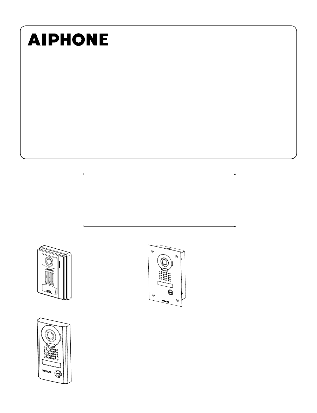
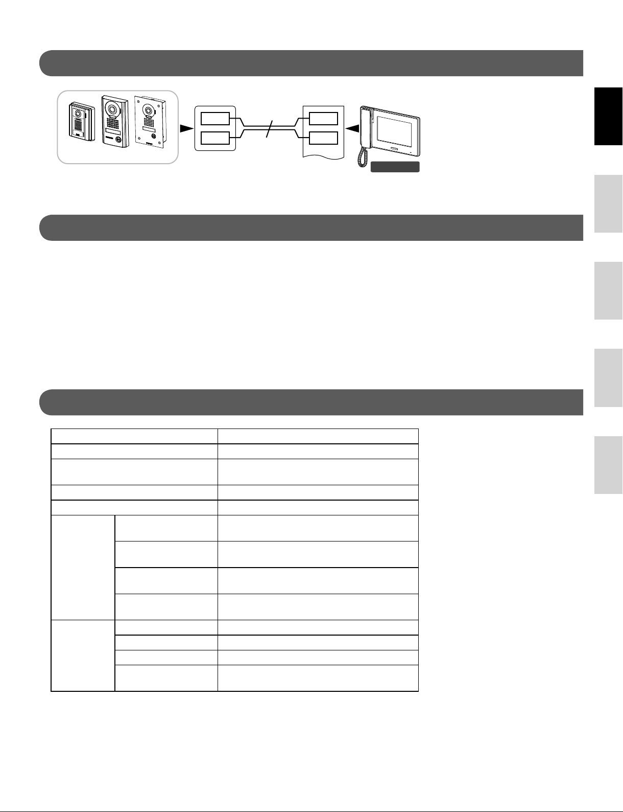
JP-DA, JP-DV, JP-DVF
VIDEO DOOR STATION
POSTE DE PORTE VIDÉO
VIDEO PORTERO
VIDEODEURPOST
POSTAZIONE VIDEOCITOFONICA ESTERNA
INSTALLATION MANUAL
MANUEL D’INSTALLATION
MANUAL DE INSTALACIÓN
INSTALLATIEHANDLEIDING
MANUALE D’INSTALLAZIONE
JP-DA
Video door station
Poste de porte vidéo
Video portero
Videodeurpost met kunststof
opbouwbehuizing
Postazione videocitofonica
esterna
JP-DV
Vandal-resistant video door station
Portier vidéo résistant au vandalisme
Video portero antivandálico
Videodeurpost met metalen
antivandalisme-opbehuizing
Postazione videocitofonica esterna
resistente agli atti vandalici
JP-DVF
Vandal-resistant video door station
Portier vidéo résistant au vandalisme
Video portero antivandálico
Videodeurpost met inox antivandalisme-
inbouwbehuizing
Postazione videocitofonica esterna
resistente agli atti vandalici
Page 2
PRECAUTIONS
General Prohibitions Prohibition to Dismantle the Unit Prohibition on Subjecting the Unit to Water General Precautions
EnglishFrançaisEspañolNederlandsItaliano
Negligence could result in death or serious injury.
1. Do not dismantle or alter the unit. Fire or electric shock could
result.
2. Existing wiring such as chime wiring, etc. may contain high
voltage AC electricity. Damage to the unit or electric shock
could result. Wiring and installation should be done by a
qualifi ed technician.
3. This unit is not an explosion-proof unit. Do not install or use
the unit in locations that are fi lled with fl ammable gas such as
oxygen rooms. Fire or an explosion could result.
WARNING
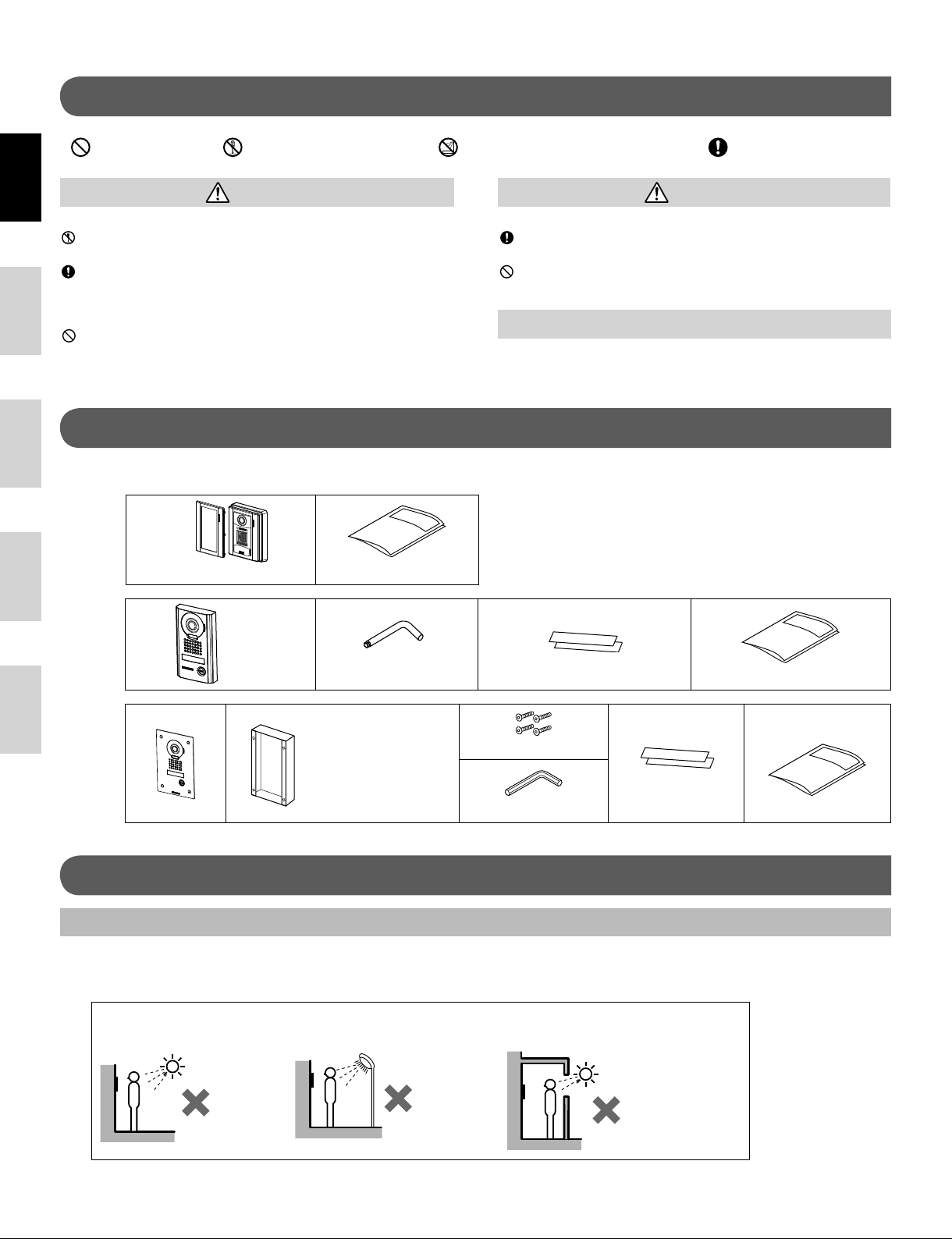
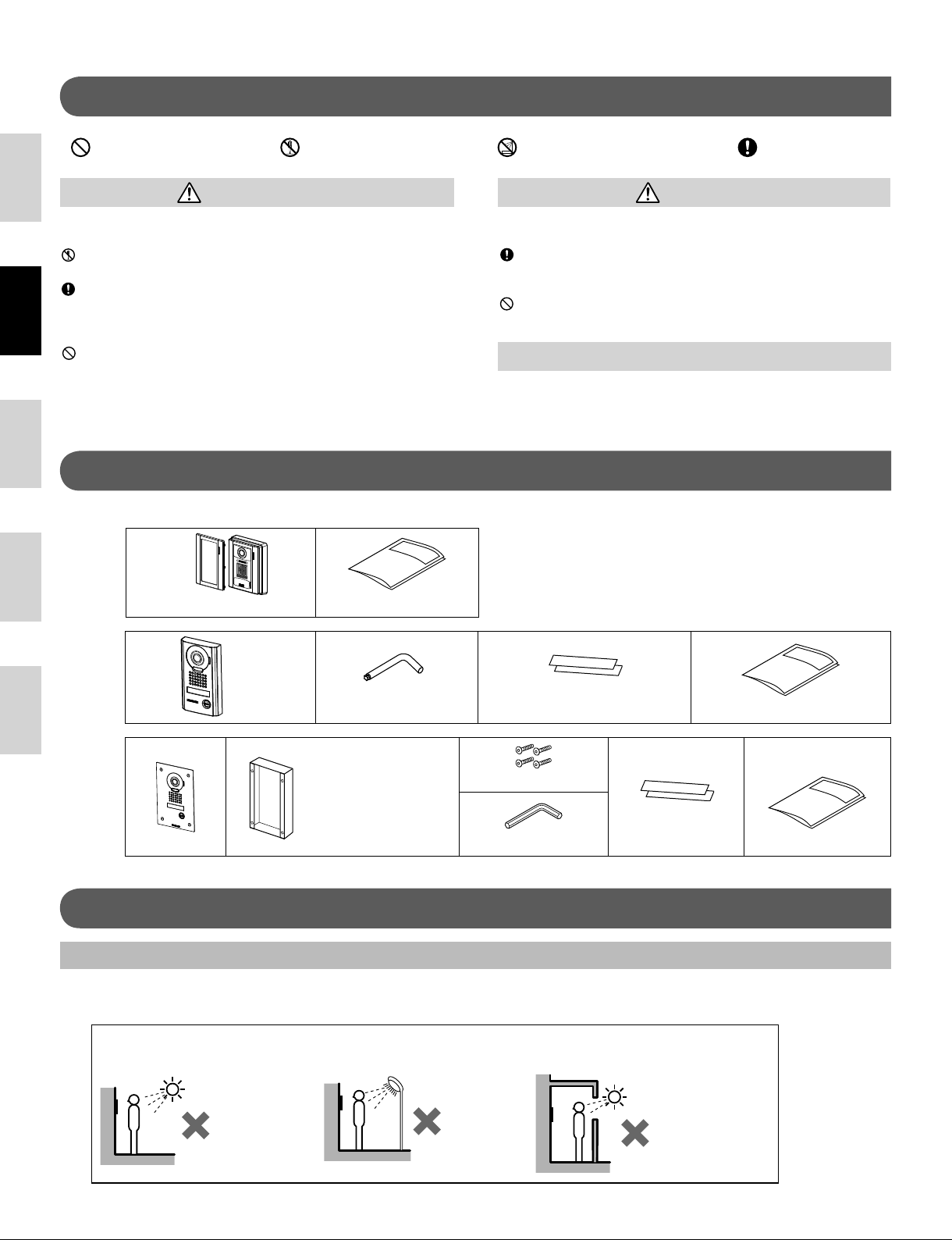
PACKAGE CONTENTS
Verify that the following parts are included.
JP-DA
Front panel Main unit Installation manual
JP-DV
CAUTION
Negligence could result in injury to people or damage to property.
1.
Before turning on power, make sure wires are not crossed or
shorted. If not, fi re or electric shock could result.
2.
Do not install or make any wire terminations while power supply
is plugged in. It can cause electrical shock or damage to the unit.
GENERAL PRECAUTIONS
1. The door station is weather resistant, but do not spray high
pressure water on door station directly. Unit trouble could result.
The unit
Special screwdriver Transparent nameplate (x2) Installation manual
JP-DVF
Special screw (x4)
Transparent
nameplate (x2) Installation manual
The unit
Flush mount back box
Hexagonal wrench
INSTALLATION
Mounting locations
"Do not install video door station in any of the following locations where lighting or the ambient environment could impact the
display on the video monitor due to the characteristics of the door station's camera."
Locations subject to
a
direct sunlight
Under street lights or door
b
lights
Other locations subject to strong
c
lighting or backlighting conditions
2
Page 3
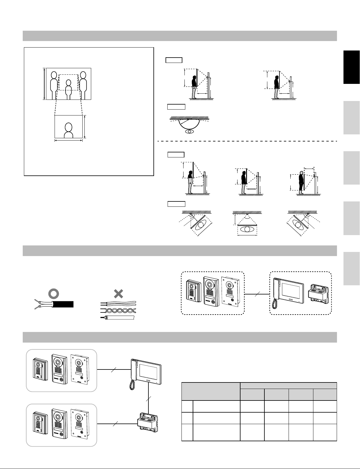
Mounting positions and image view area
A
A
A
Wide picture
◇
Objects appear smaller
◆
due to greater distortion in
the surrounding sections
Approx.
1,300 mm
(4' 3")
compared to the central
section, but a wider area is
displayed.
The display range is a rough
estimation and may change
due to the installation
environment.
Zoom picture
◇
Approx. 600 mm (2')
Approx. 950 mm (3'
The zoom position can be changed.
◆
1"
)
(Refer to the master station's operation manual.)
The factory setting is "Center" for Zoom mode.
Wide picture
◇
Up/Down
pprox. 2,200 mm
pprox. 1,300 mm (4' 3")
pprox. 900 mm
Zoom picture
◇
Approx. 2,250 mm
Approx. 750 mm (2' 5")
Approx. 1,500 mm
Approx. 500 mm (20")
(7' 2")
(2' 12")
Left/Right
Up/Down
(7' 5")
(5')
Left/Right
Approx.
Mounting position
Approx. 170°
500 mm (20")
140°
Mounting position
1,500 mm (5')
500 mm (20")
Unit center
1,500 mm (5')
An area over a range of approx. 170° in a
◆
Approx. 2,000 mm
Approx. 1,300 mm (4' 3")
Approx. 700 mm
1,300 mm (4' 3")
(6' 7")
(2' 4")
Unit center
1,300 mm (4' 3")
500 mm (20")
500 mm radius from the camera displays.
(The display range is a rough estimation
and may change due to the installation
environment.)
(when mounting position is 1,500 mm (5'))
Zoom <Up>
Approx. 1,850 mm
Unit center
Approx. 1,250 mm
1,500 mm (5')
500 mm (20")
Zoom <Left> Zoom <Center> Zoom <Right>
Approx.
85°
Approx. 500 mm
Approx.
950 mm (3' 1")
Zoom <Center> Zoom <Down>
(6' 1")
Approx. 600 mm
(2')
(4' 1")
(20")
Approx. 950 mm (
500 mm (20")
Approx.
85°
3' 1"
Unit center
1,500 mm (5')
)
Approx. 1,550 mm
Approx. 750 mm
Approx. 800 mm
950 mm (3' 1")
(2' 8")
Approx.
(5' 1")
(2' 5")
500 mm (20")
Approx.
85°
Unit center
1,500 mm (5')
Approx.
140°
Approx. 500 mm (20")
English Français Español Nederlands Italiano
Cable
Use PE (polyethylene)-insulated PVC jacket cable.
•
Parallel or jacketed 2-conductor, mid-capacitance, non-shielded
cable is recommended.
N
ever use individual conductors, twisted pair cable, or coaxial cable.
•
2
JP-DA JP-DV JP-DVF
JP-4MED
JPW-BA
Wiring distance
JP-4MED
2
[A]
JP-DA JP-DV JP-DVF
2
2
[B]
JP-DA JP-DV JP-DVF
[C]
JPW-BA
Door station - master
[A]
station
Door station - long
[B]
distance adaptor
Long distance
[C]
adaptor - master
station
Ø0.65 mm
(22 AWG)
50 m
(165')
100 m
(330')
50 m
(165')
Wire diameter
Ø0.8 mm
(20 AWG)
100 m
(330')
150 m
(490')
75 m
(245')
Ø1.0 mm
(18 AWG)
100 m
(330')
200 m
(650')
100 m
(330')
Ø1.2 mm
(16 AWG)
100 m
(330')
200 m
(650')
100 m
(330')
3
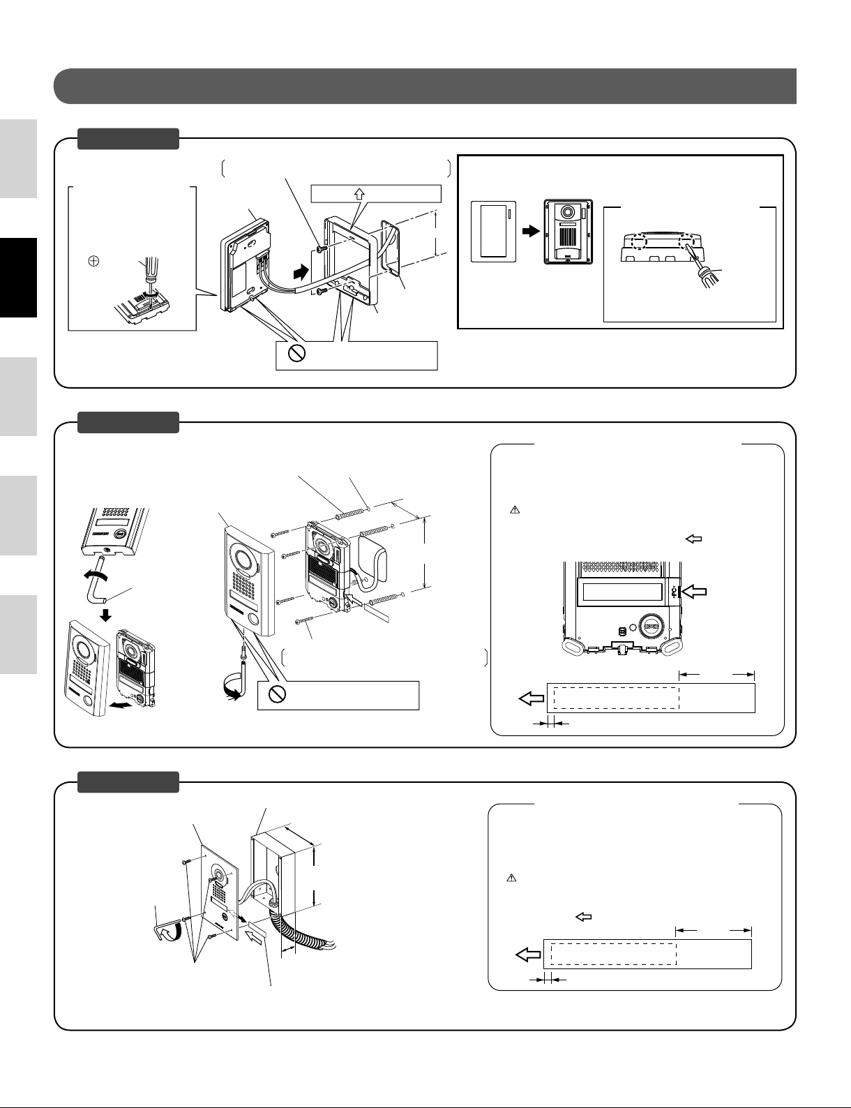
Page 4
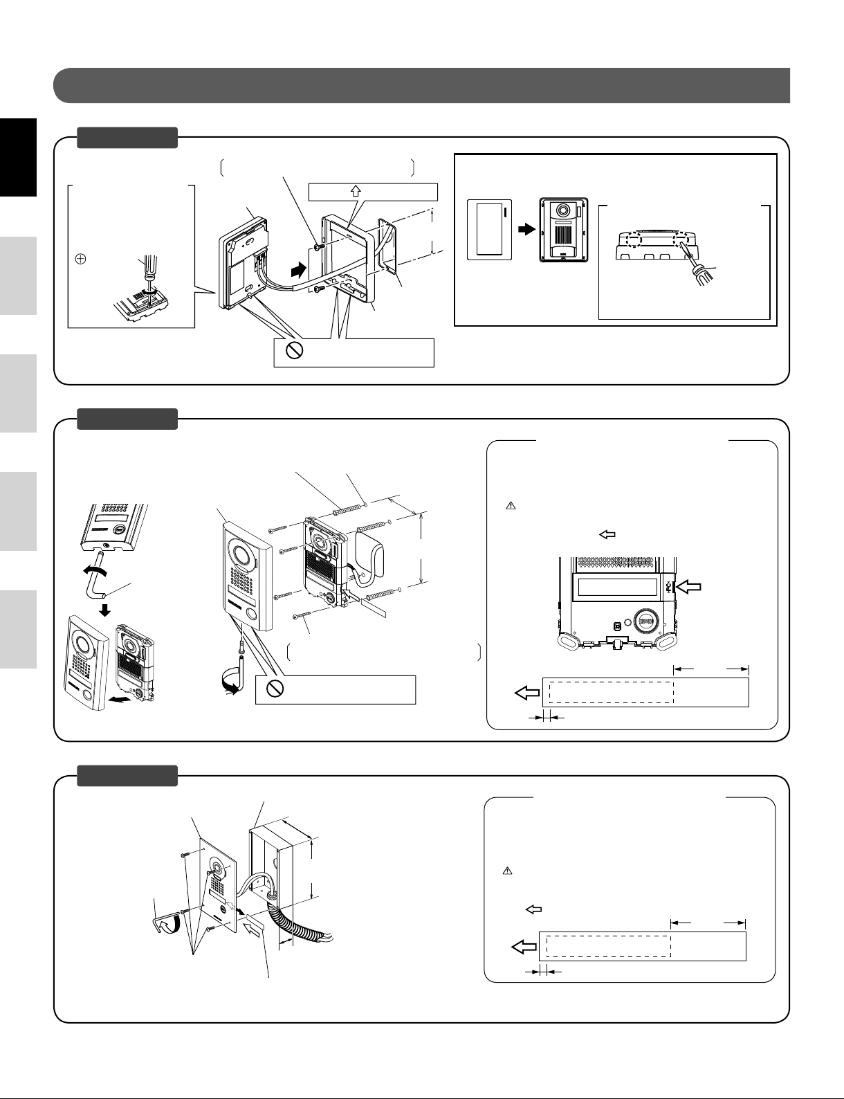
MOUNTING
EnglishFrançaisEspañolNederlandsItaliano
JP-DA
Removing the
①
main unit from the
mounting frame
Remove the main unit.
(Loosen the locking screws.)
Screwdriver
Tighten Loosen
JP-DV
Anchor × 4 (not included)
(Prepare anchors according to the
size of the mounting screws.)
Vandal-resistant front panel
Loosen
Special
screwdriver
Mounting screw × 2 (not included)
Screw shaft: Ø4.1 or less
Slotted head: Ø8.2 or less, 3.0mm or less in height
②
Main unit
Place " UP" upwards
Drainage hole
Do not block the holes.
(The diameter and the depth of the
holes on the wall depend on the anchors
suitable for the mounting screws used.)
1-gang box
Mounting frame
75 mm
150 mm
(5-15/16'')
83.5 mm
(3-5/16")
(3'')
Mount the main unit on the mounting frame, and fi t
③
the front panel on.
Removing the front panel
<Bottom surface>
Front panel
Inserting the transparent nameplates
① Remove the vandal-resistant front panel.
② Peel off the protective seals on the plate (both sides).
③ Fill in the name of the resident on the transparent nameplate.
④ Insert the fi lled-in transparent nameplate at the specifi ed insertion
Main unit
Pry off the front panel with
a fl athead screwdriver.
Using the transparent nameplates
Be sure to leave 25 mm (1") of white space on the right end to
account for insertion.
opening (indicated with
in diagram) as below.
Insert
transparent
nameplate here.
Flathead
screwdriver
Mounting screw × 4 (not included)
Screw shaft: Ø4.1 or less
Slotted head: Ø8.2 or less, 3.0mm or less in height
Tighten
Drainage hole
Do not block the holes.
* Remove protective fi lm from camera before use.
JP-DVF
Flush mount back box (included)
Vandal-resistant front panel
Hexagonal
wrench
Tighten
Special
×
4
screw
* Remove protective fi lm from camera before use.
110 mm
(4-3/8'')
180 mm
(7-3/32'')
45 mm
(1-25/32'')
Transparent nameplate
25 mm
(1")
ABC
2 mm (1/8")
Using the transparent nameplates
Inserting the transparent nameplates
① Remove the vandal-resistant front panel from the fl ush mount back
box.
② Peel off the protective seals on the plate (both sides).
③ Fill in the name of the resident on the transparent nameplate.
Be sure to leave 25 mm (1") of white space on the right end to
account for insertion.
④ Insert the fi lled-in transparent nameplate at the specifi ed insertion
opening on the rear side of the vandal-resistant front panel (indicated
with
in diagram).
25 mm
(1")
ABC
2 mm (1/8")
4
Page 5
WIRING
English Français Español Nederlands Italiano
A1
A2
JP-DA JP-DV JP-DVF
2
NP
TECHNICAL PRECAUTIONS
Door station is weather resistant. However, do not spray high pressure
•
water on door station directly. Unit trouble could result.
SPECIFICATIONS
1A1
1A2
JP-4MED
Cleaning:
•
◆
Clean units with a soft cloth and gentle cleaner. Do not spray cleaner
directly on unit. Do not use an abrasive cleanser or cloth.
◆
Wipe away dirt from the lens softly with a soft cloth. Observe the
following points for lens care.
- Take care not to scratch the lens.
- Do not use organic solvents other than isopropyl alcohol (IPA) and
methanol.
- Do not use thinner, benzene, etc. It may cause damage or
discoloration to the surface of the unit.
NP:
Non-polarized
Power supply Supplied from master station
Operating temperature - 10 - 60°C (+14°F - +140°F)
Camera unit Complementary metal oxide semiconductor
(CMOS)
Scanning lines 525 lines
Minimum subject illumination 5 Lux at 50 cm (1'6") distance
Dimensions JP-DA 129 (H) x 97 (W) x 30.5 (D) (mm)
5-1/8 (H) x 3-7/8 (W) x 1-3/16 (D) (inches)
JP-DV 173 (H) x 98 (W) x 27.1 (D) (mm)
6-13/16 (H) x 3-7/8 (W) x 1-1/16 (D) (inches)
JP-DVF 209 (H) x 135 (W) x exposed area 5.6 (D) (mm)
8-1/4 (H) x 5-5/16 (W) x 7/32 (D) (inches)
Flush mount back box
(JP-DVF)
Mass JP-DA Approx. 170 g (0.37 lbs.)
JP-DV Approx. 650 g (1.43 lbs.)
JP-DVF Approx. 570 g (1.26 lbs.)
Flush mount back box
(JP-DVF)
180 (H) x 110 (W) x 45 (D) (mm)
7-3/32 (H) x 4-3/8 (W) x 1-25/32 (D) (inches)
Approx. 450 g (1.0 lbs.)
5
Page 6
PRECAUTIONS
Mesures générales dʼinterdiction Interdiction de démonter lʼappareil Interdiction dʼexposer lʼappareil à lʼeau Précautions générales
EnglishFrançaisEspañolNederlandsItaliano
Le non-respect de cet avertissement risque dʼentraîner des
blessures graves, voire mortelles.
1. Ne démontez pas et ne modifi ez pas lʼunité. Vous risqueriez
de provoquer un incendie ou un choc électrique.
2. Le câblage existant peut être conducteur dʼélectricité CA. Ceci
peut endommager lʼappareil et provoquer un incendie ou une
décharge électrique. Faites réaliser les opérations de câblage
par un technicien qualifi é.
3. Cet appareil nʼest pas à lʼépreuve des explosions. Nʼinstallez
pas ou nʼutilisez pas lʼunité dans des endroits présentant des
gaz infl ammables, tels que des salles à oxygène. Un incendie
ou une explosion peut survenir.
AVERTISSEMENT
CONTENU DE L’EMBALLAGE
Vérifi ez que les éléments suivants sont inclus.
JP-DA
Face avant Unité principale Manuel d’installation
JP-DV
ATTENTION
Le non-respect de cet avertissement risque dʼentraîner des
blessures ou des dégâts matériels.
1. Avant de brancher le bloc dʼalimentation, vérifi ez que les fi ls ne
sont pas croisés ou en court-circuit. Dans le cas contraire, cela
pourrait provoquer un incendie ou un choc électrique.
2.
Ne réalisez aucune connexion de fi l lorsque lʼappareil est branché, sous
peine de provoquer une décharge électrique ou dʼendommager lʼunité.
PRÉCAUTIONS GÉNÉRALES
1.
Le poste de porte est protégé contre les intempéries, cependant ne
pulvérisez pas dʼeau sous haute pression directement sur le poste de
porte. Cela risquerait en effet de provoquer une panne de lʼappareil.
L’unité
Tournevis spécial
Etiquette porte-noms
transparente (x2) Manuel d’installation
JP-DVF
Vis spécial (x4)
Etiquette porte-noms
transparente (x2) Manuel d’installation
L’unité
Boîtier d’encastrement
Tournevis spécial
INSTALLATION
Emplacements de montage
N’installez pas le portier vidéo aux endroits repris ci-dessous où l’éclairage et l’environnement ambiant pourrait affecter l’affi chage
sur le moniteur vidéo intérieur.
Endroits directement exposés
a
à la lumière du soleil
Sous des éclairages publics
b
ou des éclairages de porte
Autres endroits fortement éclairés
c
ou à contre-jour
6
Page 7

Positions de montage et zone de vision de l’image
Image plein écran
◇
Les objets apparaissent plus
◆
petits à cause d’une plus
grande distorsion dans les
Environ
1 300 mm
sections environnantes par
rapport à la partie centrale,
mais ainsi, une zone plus
grande est affi chée.
La plage d’affi chage
est une estimation
brute et peut varier
Image Zoom
◇
suite à l’environnement
d’installation.
Environ 600 mm
Environ 950 mm
La position du zoom peut être modifi ée.
◆
(Cf. Se reporter au manuel d’utilisation du poste maître.)
Le réglage par défaut du mode Zoom est "Centré".
Image plein écran
◇
Haut/bas
Environ 2 200 mm
Environ 1 300 mm
Environ 900 mm
Gauche/droite
Environ 170°
Position de montage
1 500 mm
Centre de lʼunité
1 500 mm
500 mm
Environ 2 000 mm
Environ 1 300 mm
Environ 700 mm
Une zone de couverture s’affi che, d’environ 170°
◆
Position de montage
1 300 mm
avec un rayon de 500 mm à partir de la caméra.
500 mm
Image de zoom (lorsque la position de montage est de 1 500 mm)
◇
Haut/bas
Environ 2 250 mm
Environ 750 mm
Environ 1 500 mm
Gauche/droite
Environ 500 mm
Zoom <Haut>
500 mm
Zoom <Gauche> Zoom <Centre> Zoom <Droite>
Environ
140°
Environ
85°
(La plage d’affi chage est une estimation brute et
peut varier suite à l’environnement de l’installation.)
Zoom <Centre> Zoom <Bas>
Environ 1 850 mm
Centre de lʼunité
Environ 1 250 mm
1 500 mm
Environ 500 mm
Environ
950 mm
Environ 600 mm
Environ 950 mm
Environ
85°
500 mm
Centre de lʼunité
1 500 mm
Environ 1 550 mm
Environ 800 mm
Centre de lʼunité
1 300 mm
500 mm
Environ 750 mm
Environ
950 mm
Environ
85°
500 mm
Environ
Environ 500 mm
English Français Español Nederlands Italiano
Centre de lʼunité
1 500 mm
140°
Câble
Il est recommandé d’utiliser un câble téléphonique LYT1 8/10ème.
•
Il est recommandé d’utiliser un câble à gaine PVC isolée PE
(polyéthylène).
N’utilisez jamais de conducteurs individuels, de câble à paires
•
torsadées ou de câble coaxial.
Longueur de câblage
JP-4MED
2
[A]
JP-DA JP-DV JP-DVF
2
[C]
2
[B]
JP-DA JP-DV JP-DVF
JPW-BA
JP-DA JP-DV JP-DVF
Poste porte - poste
[A]
maître
Poste porte - adaptateur
[B]
longue distance
Adaptateur longue
[C]
distance - poste maître
2
JP-4MED
Diamètre du câble
Ø0,65 mm Ø0,8 mm Ø1,0 mm Ø1,2 mm
50 m 100 m 100 m 100 m
100 m 150 m 200 m 200 m
50 m 75 m 100 m 100 m
JPW-BA
7
Page 8
MONTAGE
EnglishFrançaisEspañolNederlandsItaliano
JP-DA
Retirer l’unité
①
principale de son
étrier
Retirez l’unité principale.
(Dévissez les vis de montage).
Tournevis
Desserrer
Serrer
JP-DV
Cheville × 4 (non inclus)
(Préparez les chevilles en fonction de
la taille des vis de montage.)
Platine face avant résistant
au vandalisme
Dévisser
Tournevis
spécial
Vis de montage × 2 (non inclus)
Diamètre de vis: Ø4,1 maximum
Tête fendue: Ø 8,2 maximum, 3,0 mm de hauteur maximum
②
Unité principale
Placez le “ HAUT”vers le haut
Etrier
Orifi ce de drainage
N’obstruez pas les orifi ces.
(Le diamètre et la profondeur des trous
dans le mur dépendent des systèmes de
fi xation utilisés, ces derniers devant être
adaptés aux vis de montage utilisées.)
83,5 mm
Boîte simple
75 mm
150 mm
Montez l’unité principale sur l’étrier et fi xez la face
③
avant.
Retrait de la face avant
<Surface inférieure>
Face avant
Unité principale
Soulevez la face avant à
l’aide d’un tournevis plat.
Utilisation des étiquettes porte-noms transparentes
Insertion des étiquettes porte-noms transparentes
① Retirez la face avant résistant au vandalisme.
② Détachez les joints de protection sur la plaque (les deux côtés).
③ Ecrivez le nom du résidant sur lʼétiquette porte-nom transparente.
Assurez-vous de laisser 25 mm dʼespace blanc à lʼextrémité droite
afi n de prendre en compte lʼinsertion.
④ Insérez lʼétiquette porte-noms transparente complétée dans
lʼouverture dʼinsertion spécifi ée (indiquée par
sur le schéma).
Insérez la plaque
porte-nom
transparente ici.
Tournevis à
tête plate
Vis de montage × 4 (non inclus)
Diamètre de vis: Ø4,1 maximum
Tête fendue: Ø 8,2 maximum, 3,0 mm de hauteur maximum
Visser
Orifi ce de drainage
N’obstruez pas les orifi ces.
* Retirez le fi lm protecteur de la caméra avant de l’utiliser.
JP-DVF
Boîtier dʼencastrement (inclus)
Face avant résistant au vandalisme
Tournevis spécial
Visser
×
Vis spécial
4
Etiquette porte-noms transparente
* Retirez le fi lm protecteur de la caméra avant de l’utiliser.
110 mm
180 mm
45 mm
25 mm
ABC
2 mm
Utilisation des étiquettes porte-noms transparentes
Insertion des étiquettes porte-noms transparentes
① Retirez la face avant de la platine résistant au vandalisme du boîtier
dʼencastrement.
② Détachez les joints de protection sur la plaque (les deux côtés).
③ Ecrivez le nom du résidant sur lʼétiquette porte-nom transparente.
Assurez-vous de laisser 25 mm dʼespace blanc à l'extrémité droite
afi n de prendre en compte l'insertion.
④ Insérez lʼétiquette porte-nom transparente remplie dans lʼouverture
dʼinsertion spécifi ée sur le côté arrière de la platine avant antivandale
(indiquée par un
dans le schéma).
25 mm
ABC
2 mm
8
Page 9

CABLAGE
English Français Español Nederlands Italiano
A1
A2
JP-DA JP-DV JP-DVF
2
NP
PRECAUTIONS TECHNIQUES
Le poste de porte résiste aux intempéries. Cependant, ne pas
•
vaporiser de l’eau à haute pression directement sur un poste de porte.
Cela risquerait en effet de provoquer une panne de l’appareil.
SPECIFICATIONS
1A1
1A2
JP-4MED
Nettoyage:
•
◆
Nettoyez les unités avec un chiffon et un produit de nettoyage doux.
Ne pulvérisez pas le produit de nettoyage directement sur l’unité.
Ne jamais utiliser de produit de nettoyage ou de chiffon abrasif.
◆
Essuyez en douceur les saletés sur l’objectif avec un chiffon doux.
Respectez les points suivants pour l’entretien de l’objectif.
- Faites attention de ne pas rayer l’objectif.
- N’utilisez pas de solvants organiques autres que de l’alcool
isopropylique (IPA) et du méthanol.
- N’utilisez pas de diluant, de benzène, etc., car cela risque de
provoquer des dommages ou une décoloration sur la surface de
l’appareil.
NP:
non polarisé
Bloc d’alimentation Fourni par poste maître
Température de fonctionnement de - 10 à 60°C
Caméra Semi-conducteur à oxyde de métal
complémentaire (CMOS)
Lignes de balayage 525 lignes
Eclairage minimum du sujet 5 Lux à 50 cm de distance
Dimensions JP-DA 129 (H) x 97 (L) x 30,5 (P) (mm)
JP-DV 173 (H) x 98 (L) x 27,1 (P) (mm)
JP-DVF 209 (H) x 135 (L) x 5,6 (P) de zone exposée (mm)
Boîtier d’encastrement
(JP-DVF)
Poids JP-DA Environ 170 g
JP-DV Environ 650 g
JP-DVF Environ 570 g
Boîtier d’encastrement
(JP-DVF)
180 (H) x 110 (L) x 45 (P) (mm)
Environ 450 g
9
Page 10

PRECAUCIONES
Prohibiciones generales Prohibición de desmantelar la unidad Prohibición de exponer la unidad al agua Precauciones generales
EnglishFrançaisEspañolNederlandsItaliano
No seguir estas instrucciones podría provocar lesiones
graves o incluso la muerte.
1. No desmantele ni modifi que la unidad. Existe peligro de
incendio o descarga eléctrica.
2. El alambrado existente, como el cableado de timbre, etc.
puede contener electricidad CA de alta tensión. Existe peligro
de daños en el aparato o descargas eléctricas. El cableado y la
instalación debe realizarla un técnico califi cado.
3. Esta unidad no es una unidad a prueba de explosiones. No
instale ni use la unidad en lugares llenos de gas infl amable,
tales como cuartos de oxígeno. Puede producirse un incendio
o una explosión.
ADVERTENCIA
CONTENIDO DEL PAQUETE
Verifi que que se hayan incluido las siguientes piezas.
JP-DA
Panel frontal Unidad principal Manual de instalación
JP-DV
PRECAUCIÓN
No seguir estas instrucciones podría causar daños físicos o materiales.
1.
Antes de encender la unidad, asegúrese de que no haya ningún
cable cruzado o en cortocircuito. De lo contrario, podrían
producirse incendios o descargas eléctricas.
2.
No instale ni realice terminaciones de alambres mientras la
unidad esté enchufada, ya que podría producir descargas
eléctricas y dañar la unidad.
PRECAUCIONES GENERALES
1.
El portero es resistente al ambiente, pero no se rocíe con agua de alta
presión sobre la puerta de forma directa. La unidad podría resultar dañada.
Unidad principal
Destornillador especial
Placa de identifi cación
transparente (x2) Manual de instalación
JP-DVF
Tornillo especial (x4)
Unidad
principal
Caja posterior de
montaje empotrado
Llave hexagonal
Placa de identifi cación
transparente (x2) Manual de instalación
INSTALACIÓN
Ubicaciones de montaje
"No instale el video portero en ninguno de los siguientes lugares donde el alumbrado o el medio ambiente podrían impactar la
visualización en el videomonitor debido a las características de la cámara del portero."
Lugares expuestos
a
directamente a la luz del sol
Bajo una luz de calle o de
b
portal
Otros lugares expuestos a condiciones
c
de iluminación excesiva o a contraluz
10
Page 11

Posiciones de montaje y área de visión
Imagen wide
◇
Los objetos parecen
◆
más pequeños debido
a mayor distorsión en
Aprox.
1.300 mm
secciones circundantes en
comparación con la sección
central, pero se visualiza un
área más amplia.
El alcance de la visualización
es un cálculo aproximado
y puede cambiar debido al
Imagen zoom
◇
ambiente de la instalación.
Aprox. 600 mm
Aprox. 950 mm
La posición del zoom (acercamiento) puede cambiarse.
◆
(Referirse al manual de funcionamiento del aparato principal.)
La confi guración de fábrica del modo Zoom es "Centro".
Imagen wide
◇
Arriba/Abajo
Aprox. 2.200 mm
Aprox. 1.300 mm
Aprox. 900 mm
Izquierda/Derecha
Imagen zoom
◇
Arriba/Abajo
Aprox. 2.250 mm
Aprox. 750 mm
Aprox. 1.500 mm
Izquierda/Derecha
Aprox.
140°
Aprox. 500 mm
Posición de montaje 1.500 mm
Centro de
la unidad
1.500 mm
500 mm
Aprox. 170°
Se visualiza un área sobre un alcance de aprox.
◆
Aprox. 2.000 mm
Aprox. 700 mm
Posición de montaje 1.300 mm
Aprox. 1.300 mm
500 mm
Centro de la unidad
1.300 mm
170° en un radio de 500 mm desde la cámara.
500 mm
(El alcance de la visualización es un cálculo
aproximado y puede cambiar debido al ambiente
de la instalación.)
(cuando la posición de montaje es de 1.500 mm)
Zoom <Arriba>
Aprox. 1.850 mm
Centro de
la unidad
Aprox. 1.250 mm
1.500 mm
500 mm
Zoom <Izquierda> Zoom <Centro> Zoom <Derecha>
Aprox.
85°
Aprox.
950 mm
Aprox. 500 mm
Zoom <Centro> Zoom <Abajo>
Aprox. 1.550 mm
500 mm
Aprox.
85°
Centro de
la unidad
1.500 mm
Aprox. 750 mm
Aprox. 800 mm
Aprox. 600 mm
Aprox. 950 mm
Aprox.
950 mm
Aprox.
85°
500 mm
Aprox.
Aprox. 500 mm
Centro de la
unidad
1.500 mm
140°
English Français Español Nederlands Italiano
Cable
Use cable con revestimiento de PVC aislado con PE (Polietileno).
•
Se recomienda el uso de cable sin funda, de media capacitancia,
de 2 conductores paralelo o con pantalla.
Nunca use conductores individuales, cable de par trenzado o cable
•
coaxial.
Distancia entre cables
JP-4MED
2
[A]
JP-DA JP-DV JP-DVF
2
[C]
2
[B]
JP-DA JP-DV JP-DVF
JPW-BA
JP-DA JP-DV JP-DVF
Estación de puerta -
[A]
Monitor principal
Estación de puerta -
[B]
Adaptador de larga
distancia
Adaptador de larga
[C]
distancia - Monitor
principal
2
JP-4MED
Diámetro del cable
Ø0,65 mm Ø0,8 mm Ø1,0 mm Ø1,2 mm
50 m 100 m 100 m 100 m
100 m 150 m 200 m 200 m
50 m 75 m 100 m 100 m
JPW-BA
11
Page 12

MONTAJE
EnglishFrançaisEspañolNederlandsItaliano
JP-DA
Retirando la unidad
①
principal del cuadro
de montaje
Retire la unidad principal.
(Afl oje los tornillos de bloqueo.)
Atornillador
Apretar Afl ojar
JP-DV
Taco × 4 (no incluido)
(Prepare los tacos acorde con el tamaño
de los tornillos de montaje.)
Panel frontal antivandálico
Afl ojar
Destornillador
especial
Tornillo de montaje × 2 (no incluido)
Eje del tornillo: Ø4,1
Cabezal con ranuras: Ø8,2 o menos, 3,0 mm o menos de altura
②
Unidad principal
o menos
Coloque " ARRIBA" hacia arriba
1 caja simple
Cuadro de montaje
Orifi cio de drenaje
No bloquee los orifi cios.
(El diámetro y la profundidad de los
orifi cios en el muro dependen de los tacos
adecuados para los tornillos de montaje
utilizados.)
83,5 mm
75 mm
150 mm
Monte la unidad principal en el cuadro de montaje
③
y coloque el panel frontal.
Para retirar el panel frontal
<Superfi cie inferior>
Panel frontal
Unidad principal
Quite el panel frontal haciendo
palanca con un destornillador plano.
Cómo usar las placas de identifi cación transparentes
Para insertar las placas de identifi cación transparentes
① Retire el panel frontal antivandálico
② Desprenda los sellos de protección en la placa (ambos lados).
Anote el nombre del residente en la placa de identifi cación transparente.
③
No olvide dejar 25 mm de espacio en blanco en la parte derecha
(quedará oculto tras la inserción).
④ Inserte la placa de identifi cación transparente con el nombre en
la abertura de inserción especifi cada (indicada con
diagrama) de la siguiente manera.
Inserte la placa
transparente
para el nombre
aquí.
Destornillador
plano
en el
Tornillo de montaje × 4 (no incluido)
Apretar
Eje del tornillo: Ø4,1
Cabezal con ranuras: Ø8,2 o menos, 3,0 mm o menos de altura
Orifi cio de drenaje
No bloquee los orifi cios.
o menos
* Quite la película protectora de la cámara antes del uso.
JP-DVF
Panel frontal antivandálico
Llave
hexagonal
Apretar
Tornillo
especial
×
Caja posterior de montaje empotrado (incluida)
110 mm
180 mm
45 mm
4
Placa de identifi cación
transparente
* Quite la película protectora de la cámara antes del uso.
25 mm
ABC
2 mm
Cómo usar las placas de identifi cación transparentes
Para insertar las placas de identifi cación transparentes
① Retire el panel frontal antivandálico de la caja posterior de montaje
empotrado.
② Desprenda los sellos de protección en la placa (ambos lados).
Anote el nombre del residente en la placa de identifi cación transparente.
③
No olvide dejar 25 mm de espacio en blanco en la parte derecha
(quedará oculto tras la inserción).
④ Inserte la placa de identifi cación transparente con el nombre en la
abertura de inserción especifi cada (indicada con
en la parte posterior del panel frontal antivandálico.
en el diagrama),
25 mm
ABC
2 mm
12
Page 13

CABLEADO
English Français Español Nederlands Italiano
JP-DA JP-DV JP-DVF
A1
A2
2
NP
1A1
1A2
PRECAUCIONES DE ORDEN TÉCNICO
El portero es resistente al ambiente. Sin embargo, no se recomienda
•
que lo rocíe con agua a alta presión directamente. La unidad podría
resultar dañada.
Limpieza:
•
◆
Limpie los equipos con un paño suave y limpiador moderado. No
rocíe limpiador directamente al equipo. No utilice un producto de
limpieza ni un paño que sean abrasivos.
◆
Limpie el polvo del objetivo suavemente con un paño suave. Tenga
en cuenta las siguientes indicaciones para el cuidado de la lente.
- Tenga cuidado de no rayar la lente.
- No utilice disolventes orgánicos que no sea alcohol isopropílico
(IPA) y metanol.
- No utilice disolventes, bencina, etc. Puede provocar daños o
decoloración en la superfi cie de la unidad.
ESPECIFICACIONES
JP-4MED
NP:
No polarizado
Fuente de alimentación Proporcionada por el monitor principal
Temperatura de operación - 10 - 60°C
Cámara Semiconductor de óxido de metal complementario (CMOS)
Líneas de exploración 525 líneas
Iluminación mínima de sujeto 5 Lux a una distancia de 50 cm
Dimensiones JP-DA 129 (altura) x 97 (ancho) x 30,5 (profundidad) (mm)
JP-DV 173 (altura) x 98 (ancho) x 27,1 (profundidad) (mm)
JP-DVF 209 alto x 135 ancho x área expuesta 5,6 de profundidad (mm)
Caja posterior de
montaje empotrado
(JP-DVF)
Peso JP-DA Aproximadamente 170 g
JP-DV Aproximadamente 650 g
JP-DVF Aproximadamente 570 g
Caja posterior de
montaje empotrado
(JP-DVF)
180 (altura) x 110 (ancho) x 45 (profundidad) (mm)
Aproximadamente 450 g
13
Page 14

VOORZORGSMAATREGELEN
Algemeen verbod Verbod om het toestel te demonteren Verbod om het toestel met water in contact te brengen Algemene voorzorgsmaatregelen
EnglishFrançaisEspañolNederlandsItaliano
Niet-naleving kan de dood of ernstig lichamelijk letsel
veroorzaken.
1. Demonteer of verander het toestel niet. Dit kan brand of
elektrische schokken veroorzaken.
2. Bestaande bedrading zoals bedrading van een bel, enz. kan
hoogspanningswisselstroom bevatten. Dit kan beschadiging
van het toestel of elektrische schokken veroorzaken. De
bedrading en installatie moeten door een vakman worden
uitgevoerd.
3. Dit toestel is niet bestand tegen explosies. Gebruik of installeer
het toestel niet op plaatsen waar ontvlambaar gas aanwezig
is, zoals zuurstofkamers. Dit kan brand of een explosie
veroorzaken.
WAARSCHUWING
INHOUD VAN DE VERPAKKING
Controleer of de volgende onderdelen zijn meegeleverd.
JP-DA
Deurpost + afwerkkader Installatiehandleiding
JP-DV
OPGELET
Niet-naleving kan lichamelijk letsel of materiële schade
veroorzaken.
1. Controleer of de draden niet gekruist of kortgesloten zijn
alvorens de stroom in te schakelen. Zo niet kan brand of een
elektrische schok ontstaan.
2. Sluit niets aan of sluit geen draden af terwijl de voeding is
aangesloten. Dit kan elektrische schokken of schade aan het
toestel veroorzaken.
ALGEMENE VOORZORGSMAATREGELEN
1.
De buitenpost is weerbestendig, maar spuit geen water onder hoge
druk rechtstreeks op de buitenpost. Dit kan het toestel beschadigen.
Deurpost
Speciale sleutel Doorschijnend naamplaatje (x 2) Installatiehandleiding
JP-DVF
Speciale schroeven (x 4)
Doorschijnend
naamplaatje (x 2) Installatiehandleiding
Deurpost
Inbouwmontagedoos
Zeskantsleutel
INSTALLATIE
Montageplaatsen
Voor een optimale beeldkwaliteit dient de deurpost zodanig te worden opgesteld dat er geen lichtbron komt achter het object dat in
beeld wordt gebracht (tegenlicht).
(Lage) zon achter de
a
bezoeker
Straatverlichting of tuinverlichting
b
achter de bezoeker
Camera in schaduwrijke omgeving
c
met meer licht op de achtergrond
14
Page 15

Montagestanden en gezichtsveld
Breedbeeld
◇
Voorwerpen aan de rand van
◆
het beeld zien er kleiner uit
door de grotere vervorming
Ong.
1.300 mm
Ingezoomd
◇
t.o.v. het centrale gedeelte
De weergegeven maten zijn
indicatief
beeld
Ong. 600 mm
Ong. 950 mm
De zoompositie kan worden gewijzigd.
◆
(Raadpleeg de bedieningshandleiding van de hoofdpost)
De fabrieksinstelling voor de zoompositie is in centraal.
Breedbeeld
◇
Omhoog/Omlaag
Ong. 2.200 mm
Ong. 1.300 mm
Ong. 900 mm
Gauche/droite
Montageschroeven 1.
500 mm
Ong. 170°
500 mm
Midden van het toestel
1.500 mm
Horizontaal heeft de camera in breedhoekmodus
◆
Ong. 2.000 mm
Ong. 1.300 mm
Ong. 700 mm
een bereik van ongeveer 170°.
500 mm
Ingezoomd beeld (bij een montagehoogte van 1.500 mm)
◇
Vertikaal
Ong. 2.250 mm
Ong. 1.500 mm
Horizontaal
Ong. 750 mm
Ong. 140°
Ong. 500 mm
Zoom <Omhoog>
500 mm
Zoom <Links> Zoom <Midden> Zoom <Rechts>
Ong.
85°
(De weergegeven waarden zijn benaderend en
kunnen verschillen afhankelijk van de situatie)
Zoom <Midden> Zoom <Omlaag>
Ong. 1.850 mm
Midden van
het toestel
Ong. 600 mm
Ong. 1.250 mm
1.500 mm
Ong.
950 mm
Ong. 500 mm
500 mm
Ong.
85°
Ong. 950 mm
Montageschroeven 1.300 mm
Midden van het toestel
1.300 mm
500 mm
Ong. 1.550 mm
Midden van
het toestel
1.500 mm
Ong. 750 mm
Ong. 800 mm
Ong.
950 mm
Ong.
85°
500 mm
Ong.
Ong. 500 mm
Midden van
het toestel
1.500 mm
140°
English Français Español Nederlands Italiano
Kabel
Gebruik kabel met massieve geleiders, voorzien van
•
polyethyleenisolatie.
Gebruik nooit individuele geleiders of coaxkabel.
•
Bekabelingsafstand
2
[A]
JP-DA JP-DV JP-DVF
2
[B]
JP-DA JP-DV JP-DVF
JP-4MED
2
[C]
JPW-BA
2
JP-DA JP-DV JP-DVF
Ø0,65 mm Ø0,8 mm Ø1,0 mm Ø1,2 mm
Deurpost - hoofdpost 50 m 100 m 100 m 100 m
[A]
Deurpost -
[B]
langeafstandsadapter
Langeafstandsadapter
[C]
- hoofdpost
100 m 150 m 200 m 200 m
50 m 75 m 100 m 100 m
JP-4MED
Kabeldiameter
JPW-BA
15
Page 16

MONTAGE
EnglishFrançaisEspañolNederlandsItaliano
JP-DA
De deurpost van
①
het montagekader
verwijderen.
Draai de schroeven los om
het kader te demonteren
Schroevendraaier
Vastzetten
Losdraaien
JP-DV
Plug x 4 (niet inbegrepen)
(Bereid pluggen voor met een geschikte grootte
voor de bijgeleverde montageschroeven.)
beveiligd frontpaneel
Losdraaien
Speciale
sleutel
Montageschroeven × 2 (niet meegeleverd)
Schroefas: Ø 4,1 of minder
Kop: Ø 8,2 of minder, 3,0 mm of minder hoog
②
Deurpost
Tegen vandalisme
Plaats " UP" omhoog
83,5 mm
Inbouwdoos
Montagekader
Ventilatieopeningen
Blokkeer de gaten niet.
(De diameter en de diepte van de gaten in
de muur zijn afhankelijk van de pluggen en
de gebruikte montageschroeven.)
75 mm
150 mm
Monteer de deurpost terug op het montagekader,
③
en plaats er het afwerkkader op.
Afwerkkader verwijderen
<Onderkant>
Frontpaneel
De doorschijnende naamplaatjes insteken
① Verwijder het tegen vandalisme beveiligd frontpaneel.
② Verwijder de beschermende folie van het plaatje (beide zijden).
③ Vul de naam van de bewoner in op het doorschijnende naamplaatje.
④ Schuif het ingevulde doorzichtige naamplaatje in de gespecifi ceerde
Deurpost
De doorschijnende naamplaatjes gebruiken
Zorg dat u rechts 25 mm vrije ruimte overhoudt voor het inbrengen
van het plaatje.
inschuifopening (aangegeven met
hieronder wordt getoond.
Platkopschroevendraaier
Haal het frontpaneel eraf met
een platkopschroevendraaier.
in de tekening) zoals
Doorzichtig
naamplaatje
hier plaatsen.
Montageschroeven × 4 (niet meegeleverd)
Schroefas: Ø 4,1 of minder
Kop: Ø 8,2 of minder, 3,0 mm of minder hoog
Vastzetten
Ventilatieopeningen
Blokkeer de gaten niet.
* Verwijder de beschermfolie van de camera voor gebruik.
JP-DVF
Inbouwmontagedoos (meegeleverd)
Tegen vandalisme beveiligd frontpaneel
Zeskantsleutel
Vastzetten
Speciale
×
schroeven
4
Doorschijnend naamplaatje
* Verwijder de beschermfolie van de camera voor gebruik.
110 mm
180 mm
45 mm
25 mm
ABC
2 mm
De doorschijnende naamplaatjes gebruiken
De doorschijnende naamplaatjes insteken
① Verwijder het tegen vandalisme beveiligd frontpaneel van de
inbouwmontagedoos.
② Verwijder de beschermende folie van het plaatje (beide zijden).
③ Vul de naam van de bewoner in op het doorschijnende naamplaatje.
Zorg dat u rechts 25 mm vrije ruimte overhoudt voor het inbrengen
van het plaatje.
④ Steek het ingevulde doorschijnende naamplaatje in de voorgeschreven
insteekopening aan de achterkant van het tegen vandalisme beveiligd
frontpaneel (op het schema aangeduid met
).
25 mm
ABC
2 mm
16
Page 17

BEDRADING
English Français Español Nederlands Italiano
JP-DA JP-DV JP-DVF
A1
A2
2
NP
1A1
1A2
JP-4MED
TECHNISCHE VOORZORGSMAATREGELEN
De buitenpost is weerbestendig, maar spuit geen water onder hoge
•
druk rechtstreeks op de buitenpost. Dit kan het toestel beschadigen.
Reiniging:
•
◆
Maak de toestellen met een zachte doek en een neutraal
reinigingsmiddel schoon. Gebruik geen schoonmaakspray
rechtstreeks op het toestel. Gebruik geen schurend reinigingsmiddel
of doek.
◆
Veeg vuil op de lens voorzichtig af met een zachte doek. Houd u
aan de volgende punten voor onderhoud van de lens.
- Let op dat u geen krassen maakt op de lens.
- Gebruik geen organische oplosmiddelen behalve isopropylalcohol
(IPA) en methanol.
- Gebruik geen verfverdunner, benzeen enz. Deze kunnen
beschadiging of verkleuring van het oppervlak van het toestel
veroorzaken.
NP:
Niet-gepolariseerd
TECHNISCHE GEGEVENS
Voeding Geleverd door hoofdpost
Bedrijfstemperatuur - 10 - 60 °C
Camera CMOS-technologie
Videostandaard NTSC
Minimale verlichting 5 Lux op 50 cm afstand
Afmetingen JP-DA 129 (H) x 97 (W) x 30,5 (D) (mm)
JP-DV 173 (H) x 98 (W) x 27,1 (D) (mm)
JP-DVF 209 (H) x 135 (B) x blootgestelde zone 5,6 (D) (mm)
Inbouwmontagedoos
(JP-DVF)
Gewicht JP-DA Circa 170 g
JP-DV Circa 650 g
JP-DVF Circa 570 g
Inbouwmontagedoos
(JP-DVF)
180 (H) x 110 (W) x 45 (D) (mm)
Circa 450 g
17
Page 18

PRECAUZIONI
Divieti generici Divieto di smontare lʼunità Divieto di esporre lʼunità allʼacqua Precauzioni generali
EnglishFrançaisEspañolNederlandsItaliano
Il mancato rispetto di quanto indicato potrebbe causare
lesioni gravi o incidenti anche mortali.
1. Non smontare, non manomettere lʼunità. Pericolo di incendio o
di scarica elettrica.
2. I cavi esistenti, per esempio quelli del cicalino, ecc. potrebbero
portare elettricità C.A. ad alta tensione. Lʼunità potrebbe restare
danneggiate oppure si potrebbe verifi care una scarica elettrica.
La posa dei cavi e lʼinstallazione devono essere effettuate da
un tecnico qualifi cato.
3.
Questʼunità non è a prova di esplosione. Non installare, non usare
lʼunità in luoghi saturi di gas infi ammabili, per esempio le camere
dellʼossigeno. Ne potrebbe derivare un incendio o unʼesplosione.
AVVERTENZA
CONTENUTO DELLA CONFEZIONE
Assicurarsi che i seguenti componenti siano inclusi.
JP-DA
Pannello anteriore Unità principale Manuale d’installazione
ATTENZIONE
Il mancato rispetto di quanto indicato potrebbe causare
lesioni alle persone o danni alle cose.
1. Prima di accendere lʼunità, assicurarsi che i cavi non siano
incrociati né in cortocircuito. In caso contrario, si correrebbe il
rischio di un incendio o di scarica elettrica.
2. Non installare né eseguire terminazioni con cavi se è collegata
lʼalimentazione. Tale imprudenza potrebbe causare una scarica
elettrica o danneggiare lʼunità.
PRECAUZIONI GENERALI
1. La postazione videocitofonica esterna è resistente alle intemperie,
ma è bene non spruzzare direttamente sulla postazione getti
dʼacqua ad alta pressione. Lʼunità si potrebbe guastare.
JP-DV
L’unità
Cacciavite speciale Targhetta trasparente (x2) Manuale d’installazione
JP-DVF
Vite speciale (x4)
L’unità
Scatola posteriore per
montaggio a fi lo
Chiave esagonale
Targhetta
trasparente (x2)
Manuale
d’installazione
INSTALLAZIONE
Luoghi adatti per il montaggio
"Non installare la postazione videocitofonica esterna in nessuno dei luoghi sotto indicati. Luoghi in cui la luce o l’ambiente esterno
potrebbero colpire direttamente il display del monitor per via delle caratteristiche della telecamera della postazione videocitofonica esterna."
Luoghi esposti alla luce
a
solare diretta
Sotto ai lampioni dell’illuminazione
b
pubblica o alle luci della porta
Altri luoghi esposti a forte illuminazione
c
o a luce di sfondo intensa
18
Page 19

Posizioni di montaggio ed area di visualizzazione dell’immagine
Immagine ripresa nella
◇
modalità grandangolo
Gli oggetti appaiono più
◆
piccoli a causa della
maggiore distorsione nelle
Circa
1.300 mm
parti di contorno rispetto
alla sezione centrale, ma
può essere così visualizzata
un'area più ampia.
Il campo di visualizzazione
indicato è una stima
approssimativa e può
Immagine
◇
ripresa nella
modalità
ingrandimento
variare in base all'ambiente
d'installazione.
Circa 600 mm
Circa 950 mm
La posizione di ingrandimento può essere variata.
◆
(Consultare il manuale d'uso della postazione principale).
L'impostazione predefi nita è "Centro" per la modalità di
ingrandimento.
Immagine ripresa nella modalità grandangolo
◇
Su/Giù
Circa 2.200 mm
Circa 1.300 mm
Circa 900 mm
Sinistra/Destra
Posizione di
montaggio 1.500 mm
1.500 mm
500 mm
Circa 170°
Circa 2.000 mm
Centro
dell'unità
Viene visualizzata un'area di circa 170° in un raggio
◆
di 500 mm ripresa dall'occhio della telecamera.
500 mm
(Il campo di visualizzazione indicato è una stima
approssimativa e può variare in base all'ambiente
d'installazione).
Immagine ripresa nella modalità ingrandimento
◇
Su/Giù
Circa 2.250 mm
Circa 750 mm
Circa 1.500 mm
Sinistra/Destra
Circa 500 mm
Circa 140°
Ingrandimento <Su>
Circa 1.850 mm
Centro
dell'unità
Circa 1.250 mm
1.500 mm
500 mm
Ingrandimento <Sinistra> Ingrandimento <Centro> Ingrandimento <Destra>
Circa
85°
Circa
950 mm
Circa 500 mm
Ingrandimento <Centro> Ingrandimento <Giù>
Circa 600 mm
Circa 950 mm
Posizione di
montaggio 1.300 mm
Circa 1.300 mm
Circa 700 mm
(se la posizione di montaggio è di 1.500 mm)
Centro
dell'unità
1.500 mm
500 mm
Circa
85°
500 mm
Circa 1.550 mm
Circa 750 mm
Circa 800 mm
Circa
950 mm
Centro dell'unità
1.300 mm
Circa
85°
500 mm
Centro
dell'unità
1.500 mm
Circa 140°
Circa 500 mm
English Français Español Nederlands Italiano
Cavo
Utilizzare cavi isolanti rivestiti in PVC PE (polietilene).
•
È consigliato l’uso di un cavo non schermato, di capacità media a 2
conduttori rivestiti o in parallelo.
Non utilizzare mai conduttori singoli, un cavo a doppini intrecciati o
•
un cavo coassiale.
Distanza di cablaggio
JP-4MED
2
[A]
JP-DA JP-DV JP-DVF
2
[C]
2
[B]
JP-DA JP-DV JP-DVF
JPW-BA
JP-DA JP-DV JP-DVF
Postazione di porta -
[A]
postazione principale
Postazione di porta -
[B]
adattatore per grandi
distanze
Adattatore per grandi
[C]
distanze - postazione
principale
2
JP-4MED
Diametro del cavo
Ø0,65 mm Ø0,8 mm Ø1,0 mm Ø1,2 mm
50 m 100 m 100 m 100 m
100 m 150 m 200 m 200 m
50 m 75 m 100 m 100 m
JPW-BA
19
Page 20

MONTAGGIO
EnglishFrançaisEspañolNederlandsItaliano
JP-DA
Rimozione dell'unità
①
principale dal telaio
di montaggio
Rimuovere l'unità principale.
(Allentare le viti di bloccaggio).
Cacciavite
Per stringere
Per
allentare
JP-DV
Tasselli x 4 (non inclusi)
(usare tasselli appositi in base alla
misure delle viti di fi ssaggio)
Pannello anteriore resistente
agli atti vandalici
Per allentare
Cacciavite
speciale
Vite di montaggio × 2 (non incluse)
Albero vite: Ø 4,1 o meno
Testa scanalata: Ø 8,2 o meno, 3,0 mm o meno di altezza
②
Unità principale
Posizionare la parte con il simbolo " UP" verso l'alto
Telaio di montaggio
Foro di scarico
Non otturare i fori.
(Il diametro e la profondità dei fori nella
parete dipendono dai tasselli utilizzati
con le viti di montaggio.)
83,5 mm
Scatola a muro a
1 modulo
75 mm
150 mm
Montare l'unità principale sul telaio di montaggio,
③
ed installare il pannello anteriore su di questa.
Rimozione del pannello anteriore
<Superfi cie inferiore>
Pannello
anteriore
Inserimento delle targhette trasparenti
① Rimuovere il pannello anteriore resistente agli atti vandalici.
② Staccare la pellicola protettiva dalla targhetta (sui due lati).
③ Scrivere sulla targhetta il nome dell'inquilino dell'abitazione
corrispondente.
④ Inserire la targhetta trasparente completa del nome nellʼapertura
specifi cata (indicata nel diagramma con
Unità
principale
Servendosi di un cacciavite a lama piatta,
staccare il pannello anteriore, facendo leva.
Uso delle targhette trasparenti
Assicurarsi di lasciare 25 mm di spazio sulla destra per
lʼinserimento della targhetta.
) come indicato sotto.
Inserire qui
la targhetta
indicatrice
trasparente.
Cacciavite a
lama piatta
Vite di montaggio × 4 (non incluse)
Per stringere
Albero vite: Ø 4,1
Testa scanalata: Ø 8,2 o meno, 3,0 mm o meno di altezza
Foro di scarico
Non otturare i fori.
o meno
* Rimuovere la pellicola protettiva dalla telecamera prima dell’uso.
JP-DVF
Scatola posteriore per montaggio a fi lo (inclusa)
Pannello anteriore resistente
agli atti vandalici
Chiave
esagonale
Per stringere
Vite speciale
×
4
Targhetta trasparente
* Rimuovere la pellicola protettiva dalla telecamera prima dell’uso.
110 mm
180 mm
45 mm
25 mm
ABC
2 mm
Uso delle targhette trasparenti
Inserimento delle targhette trasparenti
① Rimuovere il pannello anteriore resistente agli atti vandalici dalla
scatola posteriore per il montaggio a fi lo.
② Staccare la pellicola protettiva dalla targhetta (sui due lati).
Scrivere sulla targhetta il nome dell'inquilino dell'abitazione corrispondente.
③
Assicurarsi di lasciare 25 mm di spazio sulla destra per lʼinserimento
della targhetta.
④ Inserire la targhetta trasparente completa del nome nell'apertura
specifi cata sul retro del pannello anteriore resistente agli atti vandalici
(indicata con
nel diagramma).
25 mm
ABC
2 mm
20
Page 21

CABLAGGIO
English Français Español Nederlands Italiano
A1
2
A2
JP-DA JP-DV JP-DVF
PRECAUZIONI TECNICHE
La postazione videocitofonica esterna è resistente alle intemperie.
•
Tuttavia, è bene non spruzzare direttamente sulla postazione getti
d’acqua ad alta pressione. L’unità si potrebbe guastare.
SPECIFICHE
NP
1A1
1A2
JP-4MED
Pulizia:
•
◆
Pulire le unità con un panno soffi ce e un detergente delicato. Non
spruzzare il detergente direttamente sull’unità. Non utilizzare
detergenti o panni abrasivi.
◆
Togliere lo sporco dall’obiettivo delicatamente con un panno
morbido. Osservare i seguenti passaggi per la manutenzione
dell’obiettivo.
- Fare attenzione a non graffi are l’obiettivo.
- Non utilizzare solventi organici diversi dall’alcool isopropilico (IPA)
e dal metanolo.
- Non usare diluente, benzene, ecc. Ciò potrebbe provocare danni
o decolorazione sulla superfi cie dell’unità.
NP:
Non polarizzato
Alimentazione Fornita dalla postazione principale
Temperatura di funzionamento -10 - 60°C
Telecamera Semiconduttore ad ossido di metallo
complementare (CMOS)
Linee esploratrici 525 linee
Illuminazione minima del soggetto 5 Lux ad una distanza di 50 cm
Dimensioni JP-DA 129 (A) x 97 (L) x 30,5 (P) (mm)
JP-DV 173 (A) x 98 (L) x 27,1 (P) (mm)
JP-DVF 209 (A) x 135 (L) x area esposta 5,6 (P) (mm)
Peso
Scatola posteriore per
montaggio a fi lo
(JP-DVF)
JP-DA Circa 170 g
JP-DV Circa 650 g
JP-DVF Circa 570 g
Scatola posteriore per
montaggio a fi lo
(JP-DVF)
180 (A) x 110 (L) x 45 (P) (mm)
Circa 450 g
21
Page 22

WARRANTY
Aiphone warrants its products to be free from defects of material and workmanship under normal use and service for a period of two years after
delivery to the ultimate user and will repair free of charge or replace at no charge, should it become defective upon which examination shall disclose
to be defective and under warranty. Aiphone reserves unto itself the sole right to make the fi nal decision whether there is a defect in materials and/
or workmanship; and whether or not the product is within the warranty. This warranty shall not apply to any Aiphone product which has been subject
to misuse, neglect, accident, power surge, or to use in violation of instructions furnished, nor extended to units which have been repaired or altered
outside of the factory. This warranty does not cover batteries or damage caused by batteries used in connection with the unit. This warranty covers
bench repairs only, and any repairs must be made at the shop or place designated in writing by Aiphone. This warranty is limited to the standard
specifi cations listed in the operation manual. This warranty does not cover any supplementary function of a third party product that is added by users
or suppliers. Please note that any damage or other issues caused by failure of function or interconnection with Aiphone products is also not covered by
this warranty. Aiphone will not be responsible for any costs incurred involving on site service calls. Aiphone will not provide compensation for any loss
or damage incurred by the breakdown or malfunction of its products during use, or for any consequent inconvenience or losses that may result.
English
The object area of is the EU.
GARANTIE
Aiphone garantit que ses produits ne sont affectés d’aucun défaut de matière ni de fabrication, en cas d’utilisation normale et de réparations
conformes, pendant une période de deux ans après la livraison à l’utilisateur fi nal, et s’engage à effectuer gratuitement les réparations nécessaires
ou à remplacer l’appareil gratuitement si celui-ci présente un défaut, à la condition que ce défaut soit bien confi rmé lors de l’examen de l’appareil et
que l’appareil soit toujours sous garantie. Aiphone se réserve le droit exclusif de décider s’il existe ou non un défaut de matière et/ou de fabrication et
si l’appareil est ou non couvert par la garantie. Cette garantie ne s’applique pas à tout produit Aiphone qui a été l’objet d’une utilisation impropre, de
négligence, d’un accident, d’une surtension ou qui a été utilisé en dépit des instructions fournies ; elle ne couvre pas non plus les appareils qui ont
été réparés ou modifi és en dehors de l’usine. Cette garantie ne couvre pas les piles ni les dégâts infl igés par les piles utilisées dans l’appareil. Cette
garantie couvre exclusivement les réparations effectuées en atelier. Toute réparation doit être effectuée à l’atelier ou à l’endroit précisé par écrit par
Aiphone. Cette garantie est limitée aux spécifi cations standard répertoriées dans le manuel d’utilisation. Cette garantie ne couvre pas les fonctions
supplémentaires d’un produit tiers ajouté par les utilisateurs ou fournisseurs. Veuillez noter que les dommages ou autres problèmes causés par l’échec
de fonction ou interconnexion avec les produits Aiphone ne sont pas non plus couverts par cette garantie. Aiphone décline toute responsabilité en cas
de frais encourus pour les dépannages sur site. Aiphone n’indemnisera pas le client en cas de pertes, de dommages ou de désagréments causés par
une panne ou un dysfonctionnement d’un de ses produits lors de l’utilisation, ou pour toute perte ou tout problème qui peut en résulter.
Français
La zone d’application de est l’UE.
GARANTÍA
Aiphone garantiza que sus productos están libres de defectos de material y mano de obra, en uso y servicio normal, por un período de dos años
después de la entrega fi nal al último usuario y reparará sin costo, o reemplazará sin cargo, si llegara a resultar defectuoso, mediante una inspección
que determine que efectivamente está con defecto y en garantía. Aiphone se reserva para sí la facultad única de tomar la decisión fi nal para
juzgar si existe una falla en materiales y/o mano de obra, y si el producto está o no cubierto por la garantía. Esta garantía no se aplicará a ningún
producto Aiphone que haya sido sometido a maltrato, negligencia, accidente, sobrecarga de energía o que haya sido usado de manera diferente a
las instrucciones proporcionadas, o bien por las equipoes que hayan sido reparadas o alteradas fuera de fábrica. Esta garantía no cubre baterías o
daños causados por baterías usadas en conjunto con el equipo. La garantía cubre solo las reparaciones efectuadas en la mesa de trabajo y cualquier
reparación debe ser efectuada en el taller o lugar designado por escrito por Aiphone. Esta garantía se limita a las especifi caciones estándar indicadas
en el manual de funcionamiento. Esta garantía no cubre ninguna función adicional de un producto de terceros que haya sido añadido por los usuarios
o proveedores. Tenga en cuenta que los daños u otros problemas causados por un fallo de funcionamiento o por la interconexión con los productos de
Aiphone tampoco están cubiertos por la garantía. Aiphone no se responsabilizará por costos incurridos en cualquier llamada de servicio al sitio mismo
en que se presente el defecto. Aiphone no indemnizará por ninguna pérdida o daño en que se incurra debido a la avería o falla de sus productos
durante su uso, ni por ningún inconveniente o pérdida que se produzca como consecuencia.
Español
El área de objeto de es la UE.
22
Page 23

GARANTIE
Aiphone waarborgt zijn producten tegen materiaal- en fabricagefouten bij normaal gebruik en onderhoud gedurende een periode van twee jaar na
levering aan de eindgebruiker, en zal het product kosteloos herstellen of vervangen indien na onderzoek blijkt dat het toestel een defect heeft dat onder
de waarborg valt. Aiphone behoudt zich het recht voor als enige defi nitief te bepalen of er al dan niet sprake is van een materiaal- en/of fabricagefout
en of het product nog onder waarborg is. Deze waarborg geldt niet voor ieder Aiphoneproduct dat is blootgesteld aan verkeerd gebruik, verwaarlozing,
een ongeval, stroomstoten, of verkeerde bediening en evenmin voor toestellen die buiten de fabriek zijn hersteld of aangepast. Deze waarborg geldt
niet voor batterijen of schade veroorzaakt door batterijen die in het toestel zijn gebruikt. Deze waarborg dekt uitsluitend werkbankherstellingen en
iedere herstelling moet worden uitgevoerd in een schriftelijk door Aiphone aangewezen winkel of werkplaats. Deze waarborg beperkt zich tot de
standaardspecifi caties die in de bedieningshandleiding staan vermeld. Deze waarborg beslaat geen enkele aanvullende functie van een product van
een externe partij dat door gebruikers of leveranciers wordt toegevoegd. Gelieve op te merken dat schade of andere problemen die het gevolg zijn van
storing bij gebruik of verbinding met producten anders dan die van Aiphone, eveneens niet door deze waarborg worden gedekt. Kosten die gepaard
gaan met herstellingen ter plaatse kunnen niet worden verhaald op Aiphone. Er kan geen schadeloosstelling van Aiphone worden geëist voor enig
verlies of schade als gevolg van een defect of storing tijdens het gebruik van zijn producten, of voor enig ongemak of verlies dat hieruit voortvloeit.
Nederlands
Het toepassingsgebied van is de EU.
GARANZIA
Aiphone garantisce che i suoi prodotti sono privi di difetti nei materiali o nella lavorazione, in condizioni di utilizzo normali e per un periodo di due
anni dalla consegna all’utente fi nale. Aiphone eseguirà la riparazione o la sostituzione gratuita del prodotto qualora tale prodotto risulti difettoso e
la garanzia sia applicabile al difetto rilevato. Aiphone si riserva il diritto esclusivo di stabilire in via defi nitiva se sono presenti difetti nei materiali e/o
nella lavorazione e se il prodotto è coperto dalla garanzia oppure no. La presente garanzia non è applicabile ad alcun prodotto Aiphone che sia stato
sottoposto ad uso improprio, negligenza, incidente, sovracorrente o che sia stato utilizzato in violazione alle istruzioni fornite, né può essere estesa alle
unità che sono state riparate o manomesse al di fuori della fabbrica. Questa garanzia non copre le batterie né i danni causati dalle batterie usate in
connessione con l’unità. Questa garanzia copre solo le riparazioni del prodotto consegnato presso il punto designato. Le eventuali riparazioni devono
essere eseguite presso il punto vendita o il luogo designato per iscritto da Aiphone. Questa garanzia è limitata alle specifi che standard elencate nel
manuale d’uso. Questa garanzia non copre le funzioni supplementari di prodotti di altre aziende aggiunti dagli utenti o dai fornitori. Eventuali danni o
altri problemi causati da problemi di funzionamento o interconnessione con prodotti Aiphone non sono coperti da questa garanzia. Aiphone non potrà
essere ritenuta responsabile di eventuali costi sostenuti in caso di chiamata per l’assistenza sul posto. Aiphone non offrirà alcun compenso per gli
eventuali danni o perdite subiti a causa della rottura o del guasto dei suoi prodotti durante l’uso, o per qualsiasi disagio o perdita conseguente che si
dovesse verifi care.
Italiano
L’area oggetto di è l’UE
FCC
This device complies with Part 15 of the FCC Rules. Operation is subject to the following two conditions: (1) this device may not cause harmful
interference, and (2) this device must accept any interference received, including interference that may cause undesired operation.
This equipment has been tested and found to comply with the limits for a Class B digital device, pursuant to Part 15 of the FCC Rules. These limits are
designed to provide reasonable protection against harmful interference in a residential installation. This equipment generates, uses, and can radiate
radio frequency energy, and if not installed and used in accordance with the instructions, may cause harmful interference to radio communications.
However, there is no guarantee that interference will not occur in a particular installation. If this equipment does cause harmful interference to radio or
television reception, which can be determined by turning the equipment off and on, the user is encouraged to try to correct the interference by one or
more of the following measures:
Reorient or relocate the receiving antenna
•
Connect the equipment to an outlet on a circuit different from that to which the receiver is connected. Increase the separation between the
•
equipment and receiver.
Consult the dealer or an experienced radio/TV technician for help.
•
23
Page 24

http://www.aiphone.net/
Issue Date: Oct. 2014
FK2096 A P1014 AZ 56125
AIPHONE CO., LTD., NAGOYA, JAPAN
Printed in Thailand
 Loading...