

Page 1
JKW-IP
IP Video Intercom Adaptor
FK1594 P1210AQ 53715
AIPHONEJKW-IP
POWER
LANACT
STATUS
STRIPLENGTH
11mm
0.65〜1.2
JKW-IP
IP Video Intercom Adaptor
-
OFFPOWERON
DC18V
S1 E S2 E S3 E S4 E RY RYB1 B2 +
LAN
OPERATION MANUAL
Page 2

3
CONTENTS
INTRODUCTION .......................... 6
1
System Configuration Example ....... 6
1-1
Names ............................................7
1-2
IP Video Intercom Adaptor ..........................7
PC Application Window ...............................8
About System Settings .................. 10
1-3
Starting up the IP Video Intercom
1-4
Adaptor ..........................................12
Installing the PC Application ..........12
1-5
1-5-1 System Requirements .....................12
1-5-2 Installing ..........................................13
1-5-3 Uninstalling .....................................15
1-5-4 Starting up the PC Application ........15
Network Settings .......................16
2
PC Network Settings ..................... 16
2-1
Connecting the PC of the person
2-2
setting up the network and the
IP Video Intercom Adaptor .....
IP Video Intercom Adaptor Settings
3
Registering the IP Video Intercom
3-1
Adaptor ........................................ 18
........17
..18
PC Application Basic Operations
5
Video Intercom Functions ............. 39
5-1
5-1-1
Answering a call from the door station
5-1-2 Door release .................................. 40
5-1-3 Zoom/Wide, Pan & Tilt ....................41
5-1-4 Adjust image ...................................42
5-1-5 Room-to-room communication
(Communication with a master monitor station)
5-1-6 Entrance monitoring ....................... 44
5-1-7 Sensor Detection from Connected
Equipment ...................................... 45
5-1-8 Option Output from
IP Video Intercom Adaptor ............. 45
5-1-9 Balloon Notification ........................ 45
Recording Function .......................46
5-2
5-2-1 Auto Recording .............................. 46
5-2-2 Manual recordi
Playback Function ......................... 48
5-3
5-3-1 Play recorded image ...................... 48
5-3-2 Deleting a Recorded File ............... 49
Sending Email ............................... 49
5-4
Others ........................................ 50
6
ng ............................47
.. 39
.. 39
..42
Logging in ..................................... 20
3-2
Administrator Settings ................... 21
3-3
3-3-1 Administrator Registration...............21
3-3-2 User Registration ...........................22
Email Setting (IP Video Intercom Adaptor)
3-3-3
Sensor input / Option output Settings
3-3-4
3-3-5 Network Settings ............................ 26
Log Downloading / Firmware Update
3-3-6
User Settings ................................ 32
3-4
3-4-1 Downloading Encryption Key ..........32
3-4-2 Email Setting .................................. 33
PC Application Settings .......... 35
4
Setting the PC Application ............ 35
4-1
4-1-1 Volume Settings ............................. 35
4-1-2 Preferences Settings ..................... 36
.. 23
..24
.. 29
Technical Precautions ............. 52
Specifications ........................... 52
Settings Information Memo ..... 53
gistration .......... 54
Example of
Re
Warranty .................................... 56
2
Page 3
PRECAUTIONS
Warning and Caution General Prohibitions
WARNING
Negligence could result in death or serious injury.
1. Do not dismantle or alter the unit. Fire or electric shock
could result.
2. High voltage is present internally. Do not open the case.
Electric shock could result.
3. Do not connect any non-specified power source to the +, terminals. Also, do not install two power supplies in parallel
to a single input. Fire or damage to the unit could result.
4. Do not connect any terminal on the unit to an AC power line.
Fire or electric shock could result.
5. Do not use power supply with a voltage other than specified.
Fire or electric shock could result.
6. Keep the unit away from water or any other liquid.
Fire or electric shock could result.
7. Do not put any metal or flammable material into the unit
through the openings. Fire, electric shock, or unit trouble
could result.
CAUTION
Negligence could result in injury to people or damage
to property.
Prohibition to
Dismantle the
Unit
1. Keep the unit more than 1 m away from radio or TV set.
2. Keep the intercom wires at least 30 cm (12") away from AC
3. Install the unit in an area that will be accessible for future
4. As to other manufacturer's devices (such as sensor, detectors,
5. This unit is for indoor use only. Do not use outdoors.
6. If the unit is down or does not operate properly, unplug the
7. When wall-mounted, the top of th
8. The unit case may become warm with use, but this is not a unit
9. If a cellular phone is used close by, the unit may malfunction.
10. The unit can be damaged if dropped. Handle with care.
11. The unit turns inoperative during power failure.
12. In areas where broadcasting station antennas are close by,
Prohibition on
Subjecting the
Unit to Water
General Precautions
General Precautions
100-240 V lines. Noise and malfunction could result.
inspections, repairs, and maintenance.
door releases) used with this system, comply with the
Specifications and Warranty conditions that the manufacturers
or venders present.
power supply or turn off the POWER switches.
not indicate a malfunction.
malfunction.
the intercom system may be affect
interference.
e unit
may darken. This does
ed by radio frequency
1. Do not install or make any wire terminations while power
supply is plugged in. It can cause electrical shock or
damage to the unit.
2. When mounting the unit on a wall, install the unit in a
convenient location, but not where it could be jarred or
bumped. Injury could result.
3. Before turning on power, make sure wires are not crossed
or shorted. If not, fire or electric shock could result.
4. Do not install the unit in locations subject to frequent
vibration or impact. It may fall or tip over and possibly
damage the unit.
5. For power supply, use Aiphone power supply model or
model specified for use with system. If non-specified
product is used, fire or malfunction could result.
6.
Do not put anything on the unit or cover the unit with cloth, etc. Fire
or unit trouble could result.
7. Do not install the unit in any of the following locations. Fire,
electric shock, or unit trouble could result.
*
Places under direct sunlight or places near heating
equipment that varies in temperature.
*
Places subject to dust, oil, chemicals, etc.
*
Places subject to moisture and humidity extremes, such
as bathrooms, cellars, greenhouses, etc.
*
Places where the temperature is quite low, such as inside
refrigerated
a
*
Places subject to steam or smoke (near heating or
cooking surfaces).
*
Where noise generating devices such as dimmer switches
or inverter electrical appliances are close by.
area or in front of an air conditioner.
3
Page 4

5
Notes on Usage
•
The times for the master monitor station and the PC Application are not synchronized.
•
Lip-sync is not performed for audio and video in the PC Application.
•
Depending on the network environment and computer, it may not be useable.
•
There are times when audio and video may be delayed in the PC Application due to encoding, decoding, or the network.
•
Start the IP Video Intercom Adaptor (turn on the power) on
cables, to the master monitor station correctly. In particular, when the power for the master monitor station is turned on after
the IP Video Intercom Adaptor has started, an error sound may be generated on the computer if the PC Application cannot
connect to the master monitor station. Also, turn off the power for the IP Video Intercom Adaptor before disconnecting any
cables from the Adaptor.
•
The ID/Password to access the IP Video Intercom Adaptor is the customer's responsibility. Make sure you set a password
that cannot be easily guessed by a third party. We recommend that you change the ID/Password on a regular basis.
•
Depending on the broadband router, it may not operate. Check our website (http://www.aiphone.net/) for a list of supported
broadband routers.
•
If you cannot access the IP Video Intercom Adaptor, or if a problem occurs such as Email not being received correctly, turn
the power to the IP Video Intercom Adaptor off and then on again, and restart the main unit. If this does not fix the problem,
restart the modem or broadband router, and then restart the IP Video Intercom Adaptor.
•
See the Installation & Operation Manuals
•
Depending on the network environment or the computer's performance, operations may not be carried out normally, such as
interrupted audio or video, and delayed frame rate decrease.
•
You need a broadband connection to use this product over the Internet. Also, the broadband router needs a Static Global IP
Address.
•
We recomme
•
We do not recommend using a wireless LAN as it may not operate correctly due to security issues or communication speed
delays.
•
When operating PC Application in succession, the operation may become invalid.
•
In the event of a power breakdown or when the IP Video Intercom Adaptor is restarted, operation of PC Application is
invalid for approximately 5 minutes.
•
Use "Set
maintenance.
a 100BASE-TX wired LAN network.
nd
tings Information Memo" in page 53 and record your settings information. It will need when resetting or
provided with the Video Intercom for connection and operation procedures.
after you have connected all cables, such as wires or LAN
ly
Notes on Usage (Communication)
•
When communicating via the PC Application, use a headset to prevent feedback. When using the headset, the call tone does
not sound from the computer's speaker. Confirm the call by the headset or the screen display.
•
If there are loud noises (such as children crying, music playing, or strong winds) around the computer or the door station,
the sound may break up and be difficult to hear.
•
During
•
•
communication with the door station, if you speak before the other person has finished talking, your voice may not
come through clearly. Communication will proceed smoothly if you wait until the other person has finished before speaking.
A hands-free (VOX) system has been implemented for communication. Even if you use a headset with the PC Application,
you cannot carry out simultaneous conversations.
The talk and call tone volumes vary depending on the PC Application settings, computer settings, and headset volume. Pay
careful attention to the volume when monitoring or talking.
(Communication is not full duplex.)
4
Page 5

Notices
•
We will under no conditions be liable for damage that occurs due to failures in network equipment; failures due to internet
providers and cell phone companies; failures such as disconnected lines and other losses in communication, which render it
impossible to provide this service or in any way delay this service due to causes outside of our responsibility; or if an error
or missing data occurs during transmission.
•
We will under no conditions be liable for damage that occurs due to the inability to communicate due to malfunctions,
problems, or operational errors in this product.
•
We will under no conditions be liable for damage caused if a customer's password or transmitted information are leaked
through bugging or unlawful computer access over Internet communication.
•
We will under no conditi
•
This manual was created by Aiphone Co., Ltd., all rights reserved. Copying a part of or this entire manual without prior
permission from Aiphone Co., Ltd. is strictly forbidden.
•
Please note that images depicted in this manual may differ from the actual images.
•
Please note that this manual may be revised o
•
Please note that product specifications may be changed for the sake of improvement without prior notice.
•
Please be aware that it is the customer's responsibility to ensure that their computer is secure. We will under no conditions
be liable for security failures.
•
This system is not intended for life support or crime prevention. It is just a supplementary means of convey
Aiphone will under no conditions be liable for loss of life or property which occurs while the system is being operated.
•
When the IP Video Intercom Adaptor is initialized, all the registrations are returned to factory default settings. Follow the
setup procedure for the IP Video Intercom and the PC Application again.
be liable for any damages or losses resulting from this product's contents or specifications.
ons
r changed
without prior notice.
ing
information.
5
Page 6
INTRODUCTION
7
INTRODUCTION
1
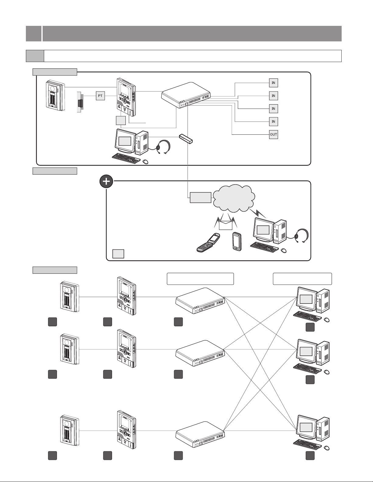
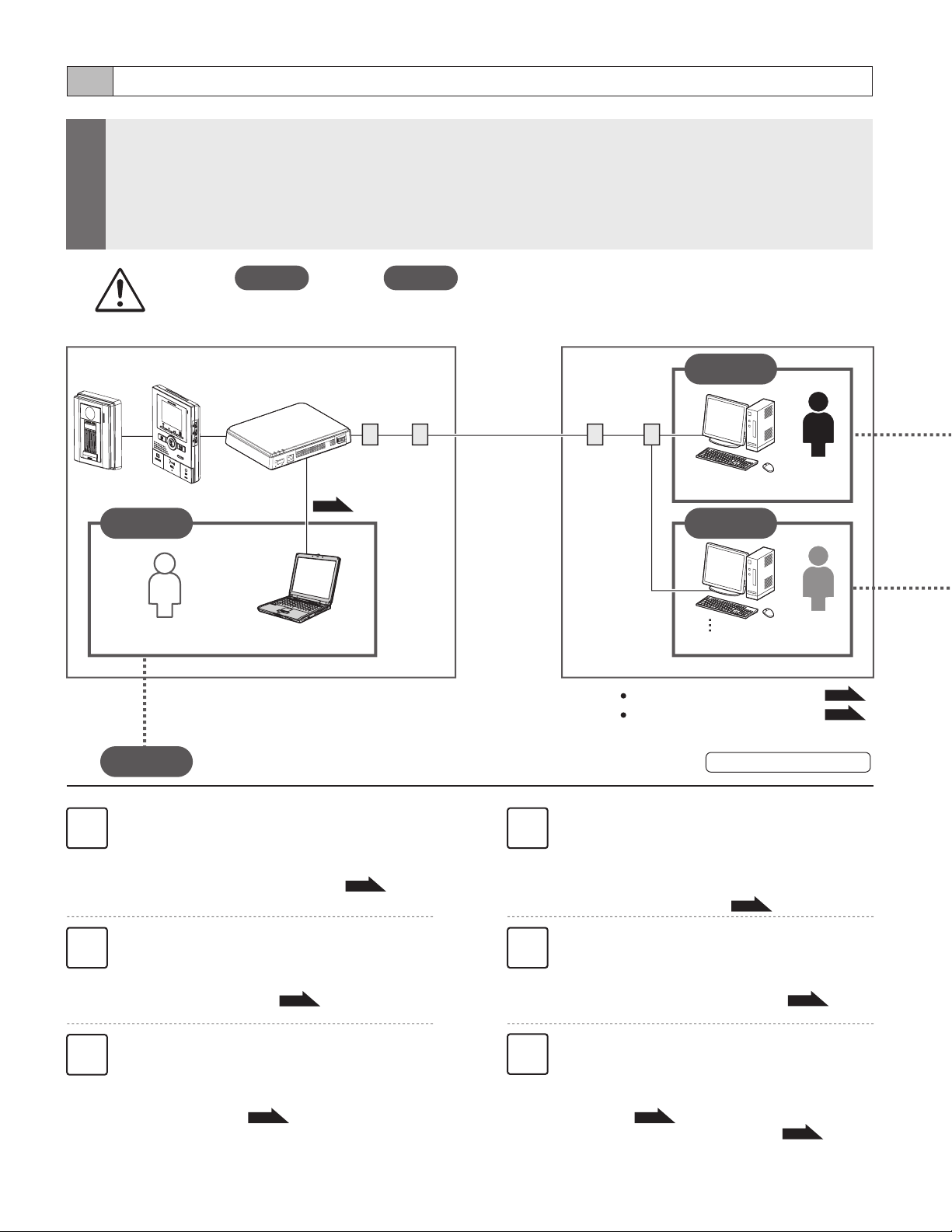
1-1 System Configuration Example
For Local
Video door station
JK-DA, JK-DV,
or JK-DVF
For Global
AC
transformer
Electronic
door lock
EL-12S
Power supply
PS-1820
Computer
Local system configuration
Application
Master monitor
station JK-1MED
or JK-1MD
PS18
Application
Sensor input
Headset
Dedicated Windows (R) application
1 Administrator, 9 Users
IP Video Intercom Adaptor
JKW-IP
AIPHONE JKW-IP
LAN ACT
STATUS
POWER
STRIP LENGTH
11mm
0.65 1.2
S1E S2 ES3 E S4E RYRYB1B2 +
LAN
CAT5e/6
(straight)
DC18V
LAN Switch
Broadband
router
-
OFF POWER ON
Internet
Email
Cell phone PDA
N.O. / N.C.
N.O.
Application
Computer
Sensor input 1
Sensor input 2
Sensor input 3
Sensor input 4
Option output 1
Headset
Entire system
Video door station
1
JK-DA, JK-DV or JK-DVF
Video door station
2
JK-DA, JK-DV or JK-DVF
Video door station
20
JK-DA, JK-DV or JK-DVF
Max. number of connected
IP Video Intercom Adaptors: 20
S1E S2 ES3 E S4E RYRYB1B2 +
LAN
S1E S2 ES3 E S4E RYRYB1B2 +
LAN
●
●
●
●
●
●
●
●
●
●
●
●
●
S1E S2 ES3 E S4E RYRYB1B2 +
LAN
-
OFF POWER ON
DC18V
-
OFF POWER ON
DC18V
-
OFF POWER ON
DC18V
AIPHONE JKW-IP
LAN ACT
STATUS
POWER
STRIP LENGTH
11mm
0.65 1.2
Master monitor station
1
JK-1MED or JK-1MD
Master monitor station
2
●
●
●
●
●
●
●
●
●
●
●
JK-1MED or JK-1MD
●
●
●
●
●
●
●
●
●
●
Master monitor station
20
JK-1MED or JK-1MD
IP Video Intercom Adaptor
1
JKW-IP
AIPHONE JKW-IP
LAN ACT
STATUS
POWER
STRIP LENGTH
11mm
0.65 1.2
IP Video Intercom Adaptor
2
JKW-IP
AIPHONE JKW-IP
LAN ACT
STATUS
POWER
STRIP LENGTH
11mm
0.65 1.2
IP Video Intercom Adaptor
20
JKW-IP
Max. number of
connected PCs: 10
Application
Computer
1
Application
Computer
2
●
●
●
●
●
●
●
●
●
●
●
●
●
Application
Computer
10
6
Page 7
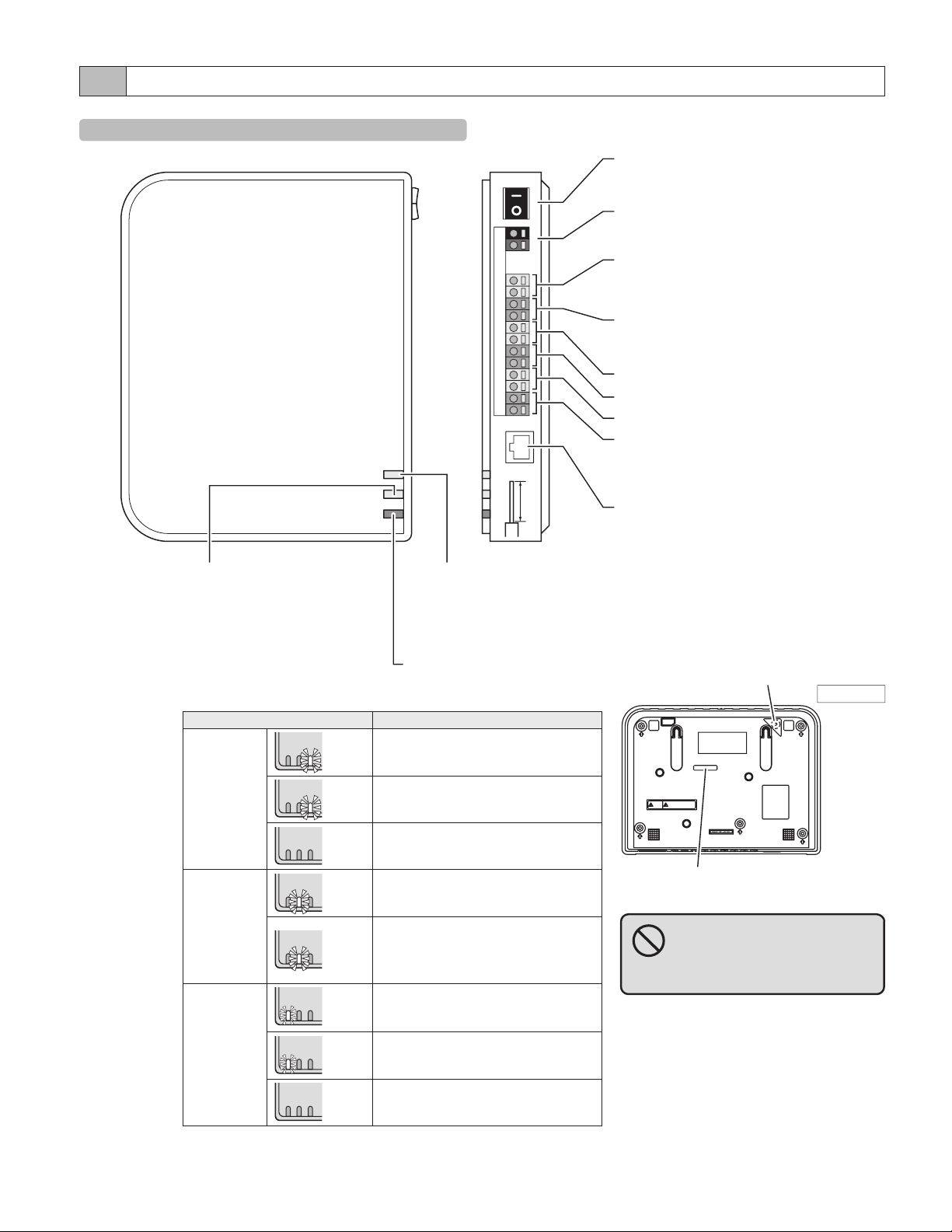
1-2 Names
IP Video Intercom Adaptor
INTRODUCTION
POWER switch
Turns the power ON or OFF.
LAN ACT
STATUS
AIPHONE JKW-IP
POWER
STATUS indicator (Orange)
Blinks orange while the system
starts up, and remains lit once
startup is complete.
Indicator operation summary
Indicator Description
LAN ACT
indicator
(Orange)
STATUS
indicator
(Orange)
POWER
POWER
POWER
POWER
POWER
POWER
LANACT
STATUS
Lit
LANACT
STATUS
Blinking
LANACT
STATUS
Off
LANACT
STATUS
Lit
LANACT
STATUS
Blinking
LANACT
STATUS
Lit
POWER ON OFF
+
DC18V
S1 E S2 E S3 E S4 E RY RY B1 B2
11mm
Ø0.65〜Ø1.2
STRIP LENGTH LAN
LAN ACT indicator (Orange)
Lit orange when a LAN is
connected, and blinks while
exchanging information over
the Ethernet.
POWER indicator (Green)
Lit green when the power is on.
•
Normal operation (When connected
to network)
•
Exchanging information with LAN
port
•
Network connection abnormality
•
Normal operation
•
Starting up
•
When the default setting switch is
pressed and held for 5 seconds or
more
•
Power is on
POWER terminal (18V DC)
Connects the power cable.
Master monitor station connection
terminal
Connects to the master monitor station.
Option output terminal
Connects output signals for option units.
Sensor input 4 terminal
Sensor input 3 terminal
Sensor input 2 terminal
Sensor input 1 terminal
Connects to buttons, sensors, etc. for option
units.
LAN port
Connects networking unit such as router.
Default setting switch (within the sticker area)
When pressed for 5 seconds or more, IP Video
Intercom Adaptor settings are returned to their
factory default settings.
Back view
MAC Address
(Do not remove.)
Never press the default setting
switch unless it is necessary.
The registered settings will return to
the default (factory) settings.
POWER
indicator
(Green)
POWER
POWER
LANACT
STATUS
Blinking
LANACT
STATUS
Off
•
Abnormality in communication with
master monitor station
•
Power is off
7
Page 8
INTRODUCTION
9
PC Application Windows
The PC Application window consists of a "Standard Window" and an "Expanded Window".
You can switch between the Standard Window and the Expanded Window by clicking the [Standard window] or [Expand
window] button.
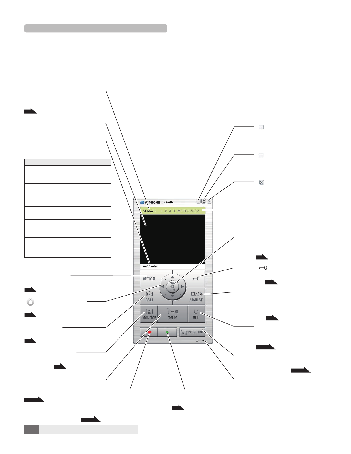
Standard Window
In the Standard Window, you can perform the following setting operations.
[SENSOR] display
Displays the status of incoming signal(s)
from option unit(s)
P.45
Screen
Displays images from the door station
[MESSAGE] display
Displays a message when a function
is operated
Message List
<Adaptor Name>
<Adaptor Name> CALL FROM DOOR <Door
station No.>
<Adaptor Name> DOOR <Door station No.>
COMMUNICATING
<Adaptor Name> DOOR <Door station No.>
MONITORING
CALLING ROOM STATION
<Adaptor Name> CALL FROM ROOM STATION
<Adaptor Name> COMMUNICATING WITH
ROOM STATION
<Adaptor Name> EXTERNAL INPUT
<Adaptor Name> EXTERNAL INPUT <No.>
<Adaptor Name> CALLING ROOM STATION
<Adaptor Name> SYSTEM IS IN
USE
[OPTION] button
Operates option unit
P.45
[ (Pan & tilt)] button
Operates Pan & Tilt on the Zoom screen
P.41
[CALL] button
Calls the master monitor station
P.43
[MONITOR] button
Displays images from the door station
on the screen
P.44
[TALK] button
Starts communication
Shortcut key: [Space]
P.39 to 40
[ (Rec) / ¢ (Stop)] button
Records the displayed image on the hard
disk drive (HDD)
Stops recording
P.46 to 47
[u (Open play window)] button
Plays back images recorded on the PC
P.48
[ (Minimize)] button
Minimizes the PC Application
window
[ (Expand window)] button
Switches to the Expanded
Window
[ (Close)] button
Closes the PC Application
Date Display
Displays the date set in the
computer
[ZOOM / WIDE] button
Switches the door station image
between wide and zoom
P.41
[ (Door release)] button
Releases the electronic door
lock
P.40
[ADJUST] button
Adjusts the image to make it
easier to see when there is
backlight in the day or when it is
dark
P.42
[OFF] button
Turns off Talk, Monitor, and Call
Shortcut key: [Esc]
P.39 to 45
[PC SETTING] button
Opens the PC Application
Settings window
P.35 to 38
Version Display
Displays the PC Application
version
MEMO
MEMO
•
•
This is the screen displayed after registration.
This is the screen displayed after registration.
8
Page 9
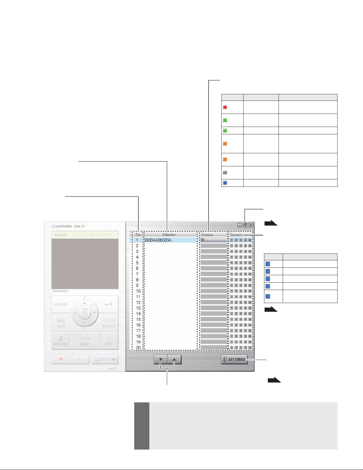
Expanded Window
The following explains the various buttons in the Expanded Window
and the display contents.
The content on the left-hand side of the window is the same as the
Standard Window.
[Adaptor] display
Displays the IP Video Intercom Adaptor Name
If no name is set, the MAC Address is displayed
[No] display
Displays the IP Video Intercom Adaptor number
Selects the IP Video Intercom Adaptor
INTRODUCTION
[Status] display
Displays the IP Video Intercom Adaptor status
Color
Red
Green
Green MONITOR
Orange
Orange
Gray <No display>
Blue <No display> Displayed during standby
With Windows 7, the color of the program displayed in
the taskbar changes linked with the [Status].
Comment Description
1 CALL DOOR
COMMUNICATION
1 CALL ROOM ST
CALL
Displayed when there is a
call from the door station
Displayed during
communication
Displayed during monitoring
Displayed when there is
a call from the master
monitor station
Displayed when there is a
call from the PC Application
Encryption key not acquired
(During standby)
[Standard window] button
Switches to the Standard Window
P.8
MEMO
[Sensor] display
Displays the status of incoming
signals from option unit(s)
Color
1
Blue Sensor input 1 active
2
Blue Sensor input 2 active
3
Blue Sensor input 3 active
4
Blue Sensor input 4 active
M
Blue
P.45
Description
Master monitor station
sensor input active
[SETTINGS] button
Opens the settings window for
the IP Video Intercom Adaptor
P.20
qp
[(
)] buttons
Changes the order of the IP Video Intercom Adaptor display
•
You can select the corresponding IP Video Intercom Adaptor by clicking the line for the
optional IP Video Intercom Adaptor. Clear the selection by clicking the selected IP Video
Intercom Adaptor again.
•
Status display cannot indicate the usage status of other PC Applications.
•
To delete an IP Video Intercom Adaptor, move the mouse's pointer to the IP Video Intercom
Adaptor you want to delete in the "
"Delete".
disconnected" status, right-click, and then select
9
Page 10
INTRODUCTION
11
1-3 About System Settings
MEMO
M
•
Be sure to check the system configuration before making settings, and then connect the units correctly.
•
You need to contact your provider (ISP) to connect to the Internet.
•
Before making settings, be sure to obtain necessary information such as the Static IP Address, Email
Addresses, and any other necessary information.
*
The factory default IP address setting of this device is 192.168.0.30. If the sam
for another device, please change the IP address for the other device.
e address is already being used
Perform through below in order to configure the product settings.
STEP 1
STEP 3
The product cannot be used unless the settings have been configured.
Site A Site B
IP Video Intercom
STEP 1
Person setting up
network
Adaptor
-
AIPHONEJKW-IP
LANACT
STATUS
POWER
STRIPLENGTH
11mm
0.65〜1.2
Network setup PC
+
B1B2
RYRY
DC18V
E S3E S4E
S2
E
S1
LAN
Connected directly
or via a hub.
P.17
OFFPOWERON
LAN
Switch
Broadband
router
Broadband
router
LAN/WAN
INTER-NET
STEP 2
LAN
Switch
Administrator PC
Administrator
STEP 3
(Up to 9 PCs)
User PCs
Settings Information Memo
Example of Registration
User
P.53
P.54
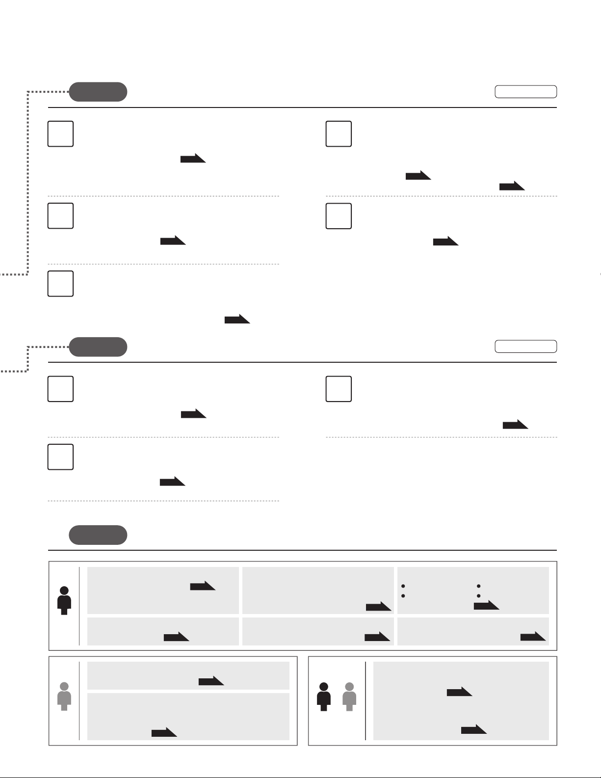
STEP 1
Starting up the IP Video Intercom Adaptor
1
Provisional registration of the IP Video Intercom
Adaptor by the person setting up the network
Turn on the power of the IP Video Intercom Adaptor
and the connected devices.
1-4 Starting up the IP Video Intercom Adaptor
Installing the PC Application
2
Install the PC Application onto the PC of the person
setting up the network.
1-5 Installing the PC Application
P.12
Network settings on the PC of the
3
person setting up the network
Set the IP address on the PC of the person setting up
the network.
2-1 PC Network Settings
P.16
P.12
10
Provisional registration
Connecting the PC of the person setting up the
4
network and the IP Video Intercom Adaptor
Connect the IP Video Intercom Adaptor and the PC of the
person setting up the network, either directly or via a hub.
2-2 Connecting the PC of the person setting up the network and
the IP Video Intercom Adaptor
Registering the IP Video Intercom Adaptor
5
Provisionally register the IP Video Intercom Adaptor in
P.17
order to configure its settings.
3-1 Registering the IP Video Intercom Adaptor
P.18
Configuring the IP Video Intercom
6
Adaptor network
Login to the IP Video Intercom Adaptor and configure
the network environment.
3-2 Logging in
3-3-5 Network Settings / Connection Settings
P.20
P.26
Page 11
INTRODUCTION
Registration of the IP Video Intercom Adaptor by the
STEP 2
Administrator
Installing the PC Application
1
Install the PC Application onto the Administrator PC.
1-5 Installing the PC Application
Administrator PC network settings
2
Set the IP Address on the Administrator PC.
2-1 PC Network Settings
Registering the IP Video Intercom Adaptor
3
Register the IP Video Intercom Adaptor in the Administrator PC.
3-1 Registering the IP Video Intercom Adaptor
STEP 3
Registration of the IP Video Intercom Adaptor by the User
P.12
P.16
P.18
Configuring the IP Video Intercom
4
Adaptor network
Login to the IP Video Intercom Adaptor and configure
the network environment.
3-2 Logging in
3-3-5 Network Settings / Connection Settings
User Registration
5
Register the User ID and User Password.
3-3-2 User Registration
P.20
P.22
Registration
P.26
Registration
Installing the PC Application
1 3
Install the PC Application onto the User PC.
2
Operational
Admini-
strator
1-5 Installing the PC Application
User PC network settings
Set the IP address on the User PC.
2-1 PC Network Settings
Settings
Changing the Administrator settings
3-3-1 Administrator Registration
User Registration
3-3-2 User Registration
After registration in the Administrator and User PCs is completed, configure the operational settings
according to the system configuration and method of administration.
P.16
P.22
P.12
P.21
Email Setting
<Sender settings>
Set the information to send concerning the Email sender.
3-3-3
Email Setting (IP Video Intercom Adaptor)
Sensor input / Option output Settings
3-3-4 Sensor input / Option output Settings
Downloading and setting the Encryption Key
3-4-1 Downloading Encryption Key
P.32
Email Setting
User
<Target setting>
Settings related to sending Email
3-4-2 Email Setting
P.33
Admini-
strator
Registering the IP Video Intercom Adaptor
Perform registration of the IP Video Intercom Adaptor
in the User PC.
3-1 Registering the IP Video Intercom Adaptor
Changing the Network Settings
Updating the Encryption Key File
Changing the Adaptor Name
P.23
3-3-5 Network Settings
Log Downloading / Firmware Update
P.24
3-3-6 Log Downloading / Firmware Update
PC Application Settings
Volume Settings
P.35
User
4-1-1 Volume Settings
Preferences Settings
4-1-2 Preferences Settings
P.26
P.36
P.18
Changing the Adaptor Language
Video Setting
P.29
11
Page 12
INTRODUCTION
13
1-4
Starting up the IP Video Intercom Adaptor
Use the following steps to start up the IP Video Intercom Adaptor.
Check that the wires are connected correctly.
1.
on all connected equipment except for the IP Video Intercom Adaptor.
Turn
2.
Turn on the POWER switch for the IP Video Intercom Adaptor.
3.
The POWER indicator (Green) and the LAN ACT indicator (Orange) light,
・
and the STATUS indicator (Orange) blinks.
LANACT
STATUS
POWER
STATUS indicator
(Orange) blinking
MEMO
For more information on the indicators, see "Indicator
operation summary" of "IP Video Intercom Adaptor" in
"Names".
The STATUS indicator (Orange) changes to lit.
4.
The IP Video Intercom Adaptor is now ready for use.
・
P.7
LANACT
STATUS
POWER
STATUS indicator
(Orange) lit
Provisional registration Registration : Administrator/User
1-5 Installing the PC Application
Provisional registration Registration : Administrator/User
Install the PC Application on your computer from the CD supplied with this product.
You may need to be logged on to your computer as the Administrator to install the PC Application.
1-5-1 System Requirements
Your computer must meet the following system requirements to use the PC Application.
Check the Operation Manual supplied with your computer.
Windows XP Home/Professional(SP3),
OS
PC system
requirements
Protocol TCP/IPv4, UDP/IPv4, SIP, Others
Network bandwidth 320 k to 8 Mbps (per IP Video Intercom Adaptor)
Language English, French, Spanish, German, Dutch, Italian, Japanese
Internet Explorer Internet Explorer 6.0 or later (with Internet Options SSL 3.0 enabled)
Windows Vista Ultimate/Home/Business/Enterprise(SP1)/32-bit version/64-bit version
Windows 7 Home Premium/Professional/Enterprise/Ultimate/32-bit version/64-bit version
Processor: 2 GHz or faster
System memory (RAM): 1 GB RAM or more
Hard disk: 10 MB or more (additional space is needed for recording)
Sound card: 8 bit full duplex, Direct Sound compatible
Display
: 1024 x 768 or greater
Run-time: Microsoft(R).NET Framework 2.0 or later
Network: 10BASE-T/100BASE-TX Ethernet
The PC Application may not run, or may not operate correctly (such as freezes occurring) on a computer with specifications
below the necessary requirements.
Serious damage could be caused if an error occurs during door release.
We recommend using a computer that exceeds the basic system requirements.
12
Page 13
1-5-2 Installing
This section describes how to install the PC Application into
your PC.
The screens may differ depending on the OS.
•
Follow the on-screen instructions to install.
•
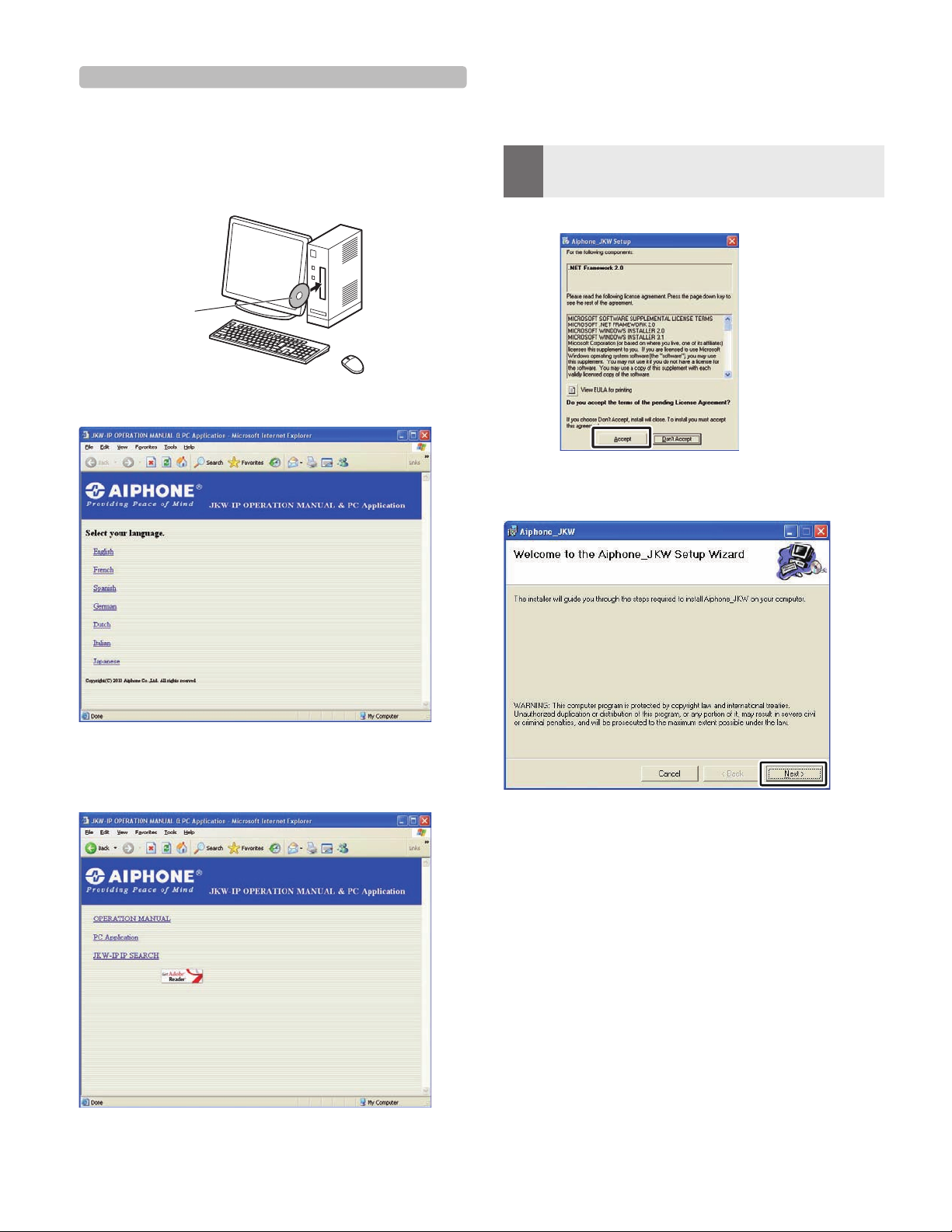
Insert the CD-ROM into your computer.
1.
Operation Manual &
Software (CD-ROM)
Click "English" on the language selection screen.
2.
INTRODUCTION
If ".NET Framework" is not already installed, the .NET
・
Framework installation window is displayed. Follow the onscreen instructions to install.
•
MEMO
4.
When starting up the application, if a security or virus
check warning is displayed, please allow the application to
continue.
Click [Next].
The Select Options window is displayed.
・
Click "PC Application", and then follow the on-screen
3.
instructions to install.
The Aiphone_JKW Setup Wizard window is displayed.
・
13
Page 14
INTRODUCTION
15
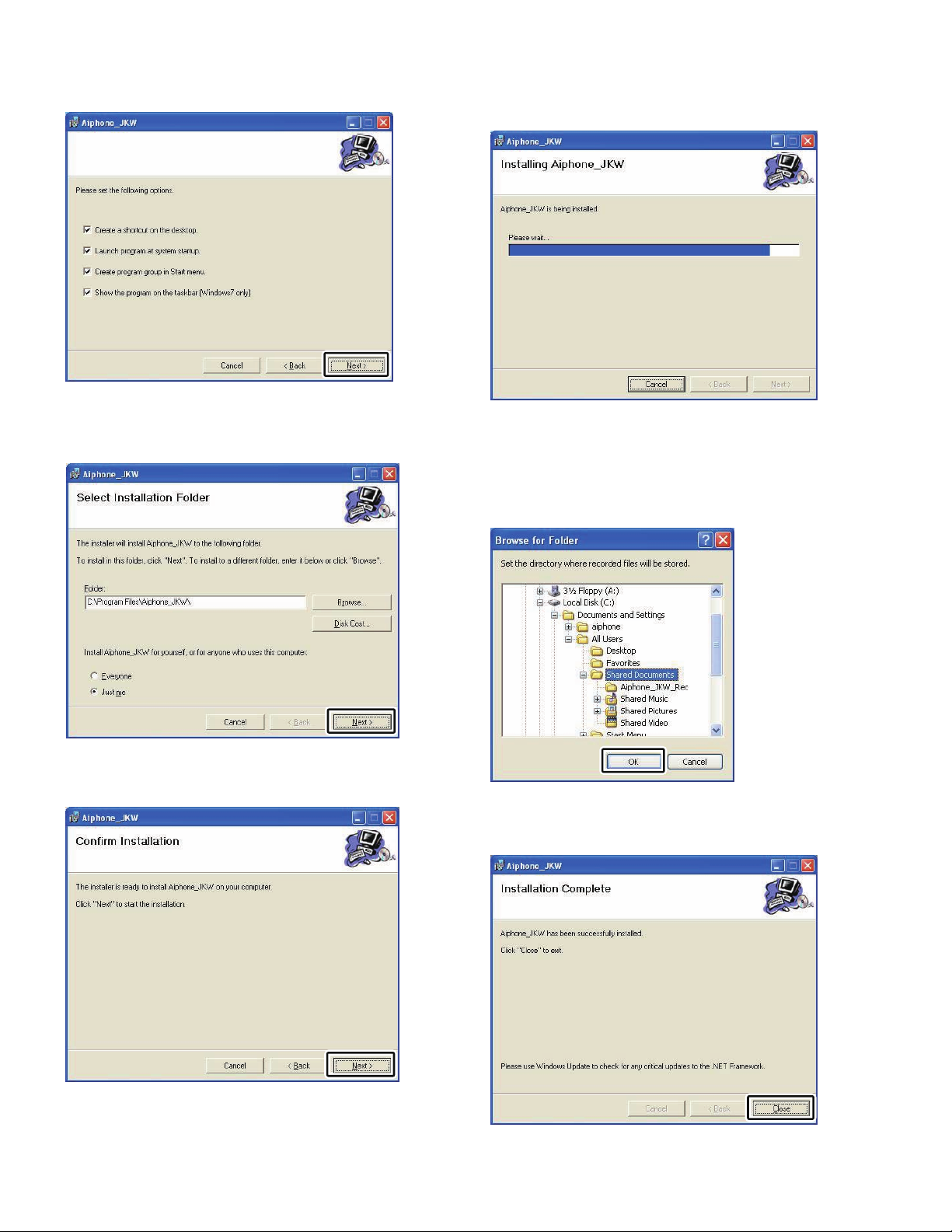
Click [Next].
5.
The Select Installation Folder window is displayed.
・
Click [Next].
6.
The folder in which the application is to be installed is
・
created.
When the installation is complete, the Select Recording
8.
File Storage Folder (Browse for Folder) window is
displayed.
Select the folder where you want to save recorded files,
9.
and then click [OK].
The selected folder becomes the storage location for recorded
・
files.
After it is selected, the saved location cannot be changed.
・
Click [Next].
7.
Installation begins.
・
14
Click [Close].
10.
Installation is complete.
・
Page 15
1-5-3 Uninstalling
From the Windows "start" menu, select "Control Panel" "
"Add or Remove Programs", and select "Aiphone_JKW" to
delete it.
•
MEMO
With Windows 7, the PC Application may still remain on
the taskbar after it is deleted. Delete the taskbar application
separately.
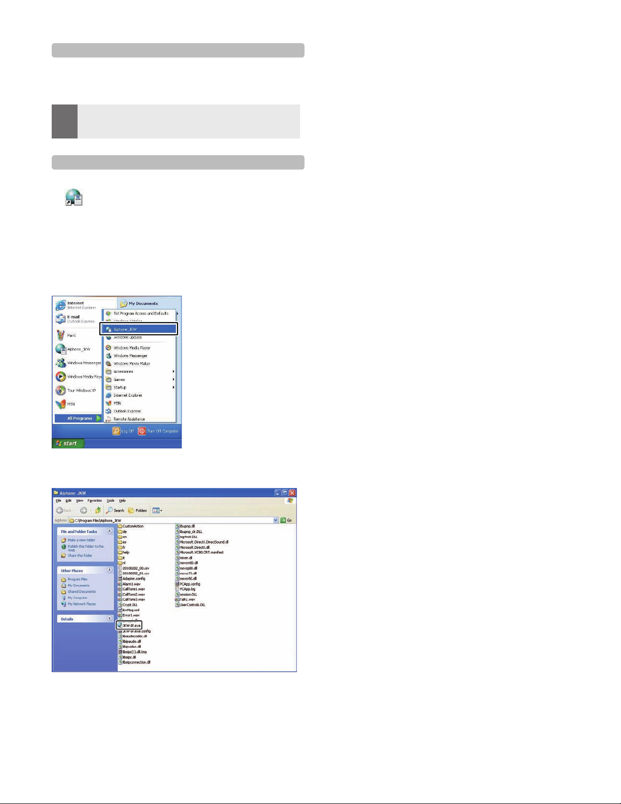
1-5-4 Starting up the PC Application
To start up the PC Application, double-click the
"
Aiphone_JKW
You can also start up the PC Application by selecting
"Aiphone_JKW" from the "All Programs" list in the "start"
menu. Alternatively, you can run "JKW-IP.exe" from the
installation folder (C:\Program Files\Aiphone_JKW).
When selecting from the "All Programs" list
" icon on the desktop.
INTRODUCTION
When running "JKW-IP.exe"
If another location is specified during installation, run
•
"JKW-IP.exe" from your selected location.
15
Page 16
Network Settings
17
Network Settings
2
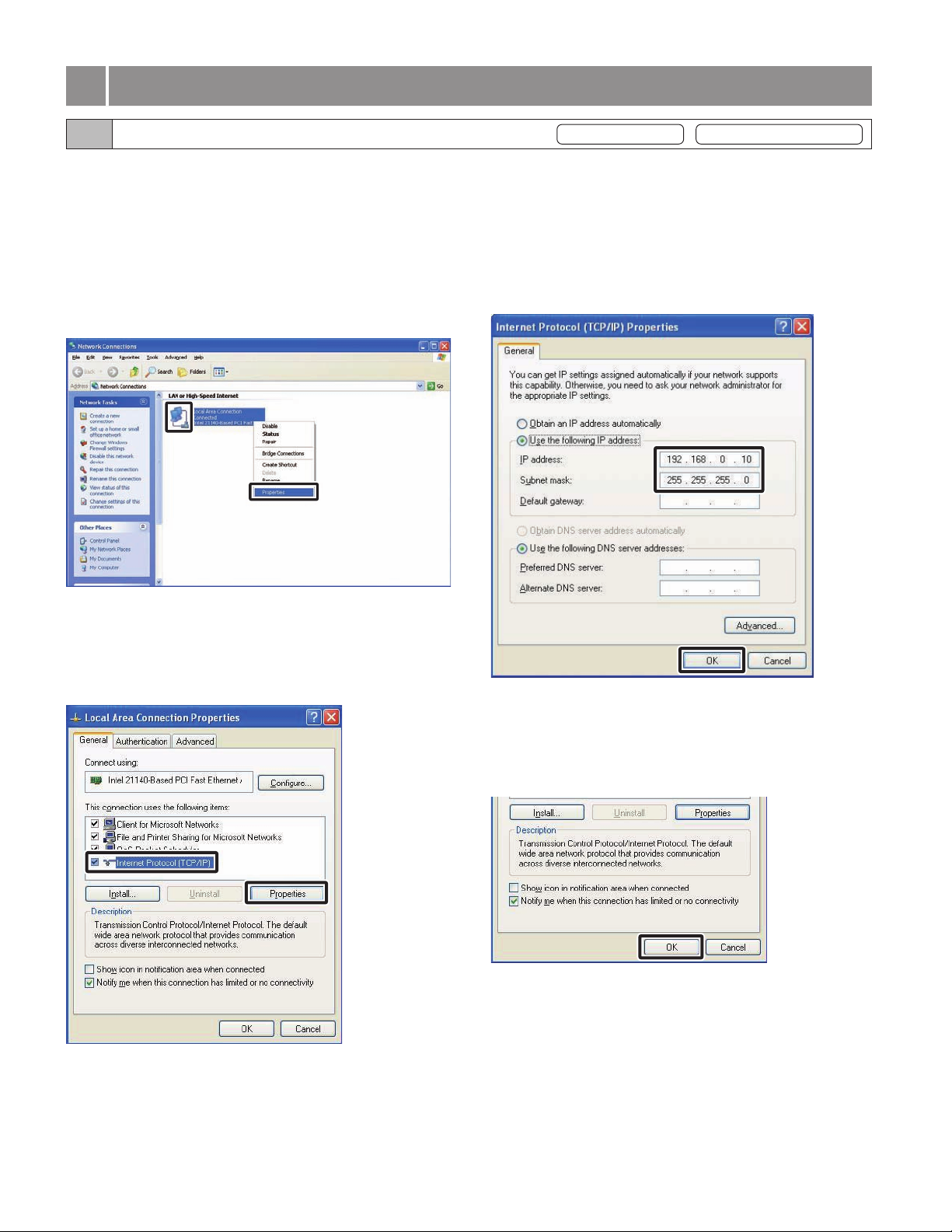
2-1 PC Network Settings
Set the IP Address, Subnet Mask, and other necessary
information on the PC of the person setting up the network,
the Administrator PC, and the User PCs, according to the
network environment.
From the Windows "start" menu, select "Control Panel"
1.
g
"Network Connections", then click "Properties" on
"Local Area Connection".
The "Local Area Connection Properties" window appears.
・
Provisional registration Registration : Administrator/User
Enter the IP Address, Subnet Mask, and other necessary
3.
information according to the network environment, then
click [OK].
For provisional registration, enter "192.168.0.10" as the
・
IP Address and "255.255.255.0" as the Subnet Mask.
All other items besides the IP Address and Subnet
Mask may be left blank.
Select "Internet Protocol (TCP/IP), then click
2.
"Properties".
The "Internet Protocol (TCP/IP) Properties" window
・
appears.
・
Click [OK] to return to the "Local Area Connection
Properties" window.
Click [OK].
4.
The PC Network Settings are now completed.
・
・
For provisional settings, after the IP Video Intercom
Adaptor settings are completed, be sure to restore the
PC network settings to their original status.
16
Page 17
Network Settings
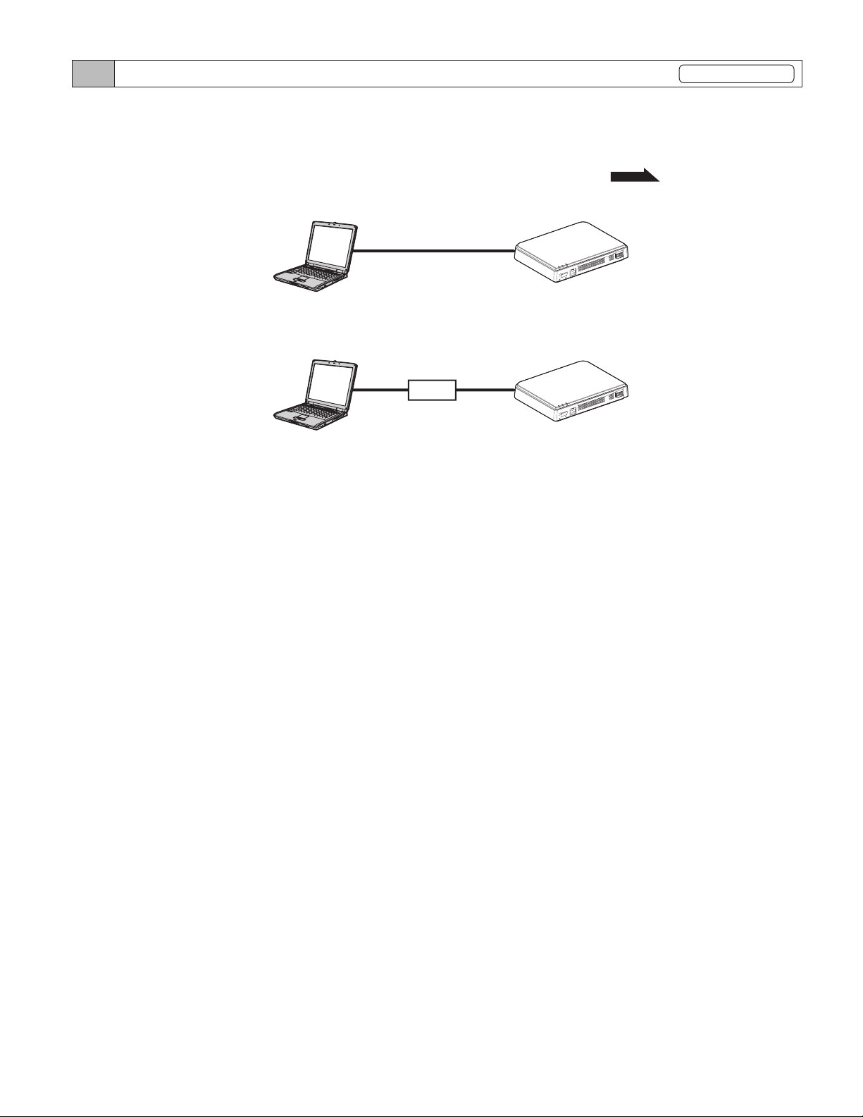
2-2
Connecting the PC of the person setting up the network and the IP Video Intercom Adaptor
Provisional registration
In order to configure the IP Video Intercom Adaptor, use a LAN cable and connect the PC of the person setting up the network
and the IP Video Intercom Adaptor.
When connecting the PC of the person setting up the network directly to the IP Video Intercom Adaptor, use an Ethernet
crossover cable. When connecting via a hub, use a straight cable.
Even if it is to be used with Global, first make broadband router settings and
Direct connection
Connecting via a hub
PC of the person setting up
the network
PC of the person setting up
the network
Ethernet crossover cable
Straight cable
HUB
Network Settings
AIPHONEJKW-IP
LANACT
STATUS
POWER
S1E S2E S3 ES4 ERYRYB1B2 +
LAN
STRIPLENGTH
11mm
0.65〜1.2
IP Video Intercom Adaptor
JKW-IP
AIPHONEJKW-IP
IP Video Intercom Adaptor
JKW-IP
RYRY
LANACT
STATUS
POWER
S2E S3E S4 E
S1E
LAN
STRIPLENGTH
11mm
0.65〜1.2
P.26 to 28
-
DC18V
-
+
B1B2
DC18V
for
Global with Local.
OFFPOWERON
OFFPOWERON
17
Page 18

IP Video Intercom Adaptor Settings
19
IP Video Intercom Adaptor Settings
3
See "Settings List"
3-1
Registering the IP Video Intercom Adaptor
for a list of the IP Video Intercom Adaptor settings.
P.50
To operate the IP Video Intercom Adaptor, you need to
register the IP Video Intercom Adaptor connected to the
system.
Register from the Adaptor list on the right-hand side of the
Expanded Window. When registration is complete, each
IP Video Intercom Adaptor name (the default is the MAC
Address) is displayed under "Adaptor" in the Adaptor list.
The registered IP Video Intercom Adaptor is automatically
recognized the next time the PC Application is started up,
and it is displayed in the IP Video Intercom Adaptor list.
•
MEMO
1.
You can change the IP Video Intercom Adaptor Name
and IP Address for each IP Video Intercom Adaptor from
Administrator Settings/Network Settings. See "Network
Settings" for more details.
•
Up to 9 Users can be registered for 1 IP Video Intercom
Adaptor.
P.26
Start up the PC Application, and display the Expanded
Window.
Provisional registration Registration : Administrator/User
Enter the unique IP Address, Connection Port, Connection
3.
Password, and Web Port for the IP Video Intercom
Adaptor to be registered.
For provisional registration, enter "192.168.0.30" as the
・
IP Address, "aiphone" as the Connection Password. The
Connection Port and Web Port may be left at their factory
default settings.
If the Administrator, enter the IP Address, Connection Port,
・
Connection Passw
at the IP Video Intercom Adaptor.
For a User, obtain the IP Address, Connection Port,
・
Connection Password and Web Port from the Administrator
in advance.
Duplicated IP Addresses cannot be set on the same LAN.
ord,
and Web Port that were previously set
Select the number where you want to register the IP
2.
Video Intercom Adaptor, right-click, and then select
"Connect" from the menu displayed.
The Adaptor Registration window is displayed.
・
For Global, enter the Global IP Address of the broadband
・
router on the IP Video Intercom Adaptor side as the IP
Address.
You need a Static Global IP Address for the Global IP
・
Address. It does not support DDNS service.
If you do not know your Local IP Address, run "JKW-IP
・
IP SEARCH" from the CD-ROM supplied, and then click
the "Search" button. It searches for the IP Video Intercom
Adaptor on the netw
and the IP Address. It is set to 192.168.0.30 at the time of
shipping.
and then displays the MAC Address
ork,
18
Page 19

Enter a valid ID and Password.
4.
If you enter the ID and Password here, you will not have to
・
enter them again when logging into the IP Video Intercom
Adaptor.
•
MEMO
5.
For provisional registration and for the Administrator, enter
"aiphone" as the ID, and "aiphone" as the Password. If they
are not entered correctly, an ID error will occur for login.
•
If a User, the ID and Password that were registered by the
Administrator in "User Registration "
P.22
are required.
Select the optional Network Interface Card (NIC): being
used.
IP Video Intercom Adaptor Settings
For Global, it may be necessary to change ports when
・
you are using multiple IP Video Intercom Adaptors or PC
Applications. Please check our homepage at http://www.
aiphone.net for more details.
For the broadband router setting information, see the
・
Operation Manual supplied with the broadband router.
You can enter only even values in both the Audio Port and
・
Video Port.
Click [OK].
7.
The Adaptor Registration window closes, and the IP Video
・
Intercom Adaptor is registered.
Select UPnP ON or OFF.
6.
For provisional registration, select ON and proceed to Step 7.
・
For Global, when using a broadband router that is confirmed
・
to support UPnP, select ON.
For Global, if the broadband router does not support UPnP,
・
or when connecting between networks, select OFF and enter
the broadband router information.
For Local, select OFF and enter the IP Address that was
・
allocated to the PC.
If the check mark is removed, the entered information is not
*
remembered.
When the IP Video Intercom Adaptor registration is
・
complete, the name of the IP Video Intercom Adaptor is
displayed in the [Adaptor] column and an icon (gray) is
displayed in the [Status] column.
•
MEMO
To make Adaptor settings, you need to enable SSL 3.0 from
Internet Options - Advanced in Internet Explorer 6.0 and
later.
19
Page 20

IP Video Intercom Adaptor Settings
21
3-2 Logging in
To modify IP Video Intercom Adaptor settings, you first
need to login.
•
MEMO
You can login as the "Administrator" or a "User". Setting
items are restricted depending on which you use to login.
Login using the following method.
1.
2.
Since you are not registered as a User before setting up, you
can only login as the Administrator.
Start up the PC Application, and select an optional
"Adaptor" from the Expanded Window.
Click [SETTINGS].
Provisional registration Registration : Administrator/User
Login is complete, and the User Settings window is
・
displayed.
Administrator / User are differentiated by the ID entered.
・
•
MEMO
If the "Status" display is not displayed, the IP Video Intercom
Adaptor is not "connected". Select the relevant IP Video
Intercom Adaptor, right-click, and then select "Connect"
from the menu displayed to connect the IP Video Intercom
Adaptor.
•
If the check mark has been removed from "Remember these
settings" in the Adaptor Registration window, you need to
enter the registration information again. See
IP Video Intercom Adaptor"
•
If no operations are performed for a set amount of time after
login, timeout automatically occurs. When an operation is
next performed, the message "The session has expired. Please
login again." is displayed. Login again.
•
If the ID and Password were not entered when the IP Video
Intercom Adaptor was registered, or if the wrong ID and
Password were entered, it will be necessary
and Password here.
P.18
"Registering the
for more details.
to enter the ID
MEMO
•
If the security warning and virus check program warning
screens are displayed during start up, please approve them.
20
Page 21

IP Video Intercom Adaptor Settings
3-3 Administrator Settings
Various Administrator settings for the IP Video Intercom
Adaptor can be made from the Administrator Settings
window while logged in as the Administrator.
•
MEMO
The following settings come under Administrator Settings.
Administrator Registration
User Registration
Email Setting (IP Video Intercom Adaptor)
Sensor input / Option output Settings
Network Settings
Log Downloading/Firmware Update
Use the following method to display the Administrator
Settings window.
1.
You cannot change settings for multiple IP Video Intercom
Adaptors at the same time. Make various settings for each IP
Video Intercom Adaptor.
Setting Item Reference
P.21
P.22
P.23
P.24
P.26
P.29
After starting up the PC Application, select an optional
"Adaptor", and then login as the Administrator.
The User Settings window is displayed.
・
Provisional registration Registration : Administrator
3-3-1 Administrator Registration
In Administrator Registration, you can change the
Administrator ID and Administrator Password. The
default settings are - Administrator ID: "aiphone" and
Administrator Password: "aiphone".
We recommend changing the default password.
•
MEMO
1.
If you are logged in as a User, you cannot perform
Administrator Registration.
Click the [Setting] button of "Administrator Registration"
from the Administrator Settings window.
The Administrator Registration window is displayed.
・
MEMO
•
See "Logging in" for more details on logging in.
Click the [Admin] tab.
2.
The Administrator Settings window is displayed.
・
•
MEMO
You cannot select the [Admin] tab when logged in as a User.
P.20
21
Enter the ID and the Current Password.
2.
You can enter up to 16 single-byte alphanumeric characters
・
for the ID.
Page 22

IP Video Intercom Adaptor Settings
23
Enter a password in New Password.
3.
You can enter up to 16 single-byte alphanumeric
・
characters for the password.
Enter the new password again in the "Re-type" field as
4.
confirmation.
3-3-2 User Registration
Registration : Administrator
Users other than the Administrator can be registered to
allow them to use the IP Video Intercom Adaptor. Enter the
User ID and User Password in User Registration.
•
MEMO
1.
If you are logged in as a User, you cannot perform User
Registration.
Click the [Setting] button of "User Registration" from
the Administrator Settings window.
The User Registration window is displayed.
・
Click [SAVE].
5.
"[Administrator Registration] Setting has been saved." is
・
displayed, the entered ID and new password are set, and you
are returned to the Administrator Settings window.
When you have changed the ID or password
・
Change the ID or password in "Registering the IP Video
Intercom Adaptor"
P.18
to the same ID or password.
Enter the User's ID and Password.
2.
You can register up to 9 users.
・
MEMO
•
Setting operations are canceled if you click [CANCEL], and
you are returned to the Administrator Settings window.
•
If you forget the registered ID or password, press the default
setting switch of the IP Video Intercom Adaptor for 5 seconds
or more to return the factory default settings. However, all
settings return to the factory default settings.
22
Page 23

Click [SAVE].
3.
"[User Registration] Setting has been saved." is displayed,
・
and you are returned to the Administrator Settings window.
•
MEMO
Setting operations are canceled if you click [CANCEL], and
you are returned to the Administrator Settings window.
•
All settings are returned to their factory default settings
if you press the IP Video Intercom Adaptor default setting
switch for 5 seconds or more.
IP Video Intercom Adaptor Settings
3-3-3
Email Setting (IP Video Intercom Adaptor)
In Email Setting, you can set information on the origin of
the sent Email.
•
MEMO
1.
If you are logged in as a User, you cannot perform Email
Setting.
•
Prepare an Email account for the IP Video Intercom Adaptor
beforehand.
Click the [Setting] button of "Email" from the
Administrator Settings window.
The Email Setting window is displayed.
・
Enter information for the "Adaptor Email Address",
2.
"SMTP Server", "(Email) login ID", "SMTP Password",
"SMTP Server Port", and "SSL"* based on your Email
account information.
For an SSL-dedicated server, select ON.
*
•
MEMO
The default SMTP Server Port setting is "465".
P.51
•
See
for the characters and symbols that can be used.
23
Page 24

IP Video Intercom Adaptor Settings
25
Click [SAVE].
3.
"[Email] Setting has been saved." is displayed, the
・
entered Email address is set, and you are returned to the
Administrator Settings window.
•
MEMO
Setting operations are canceled if you click [CANCEL], and
you are returned to the Administrator Settings window.
•
All settings are returned to their factory default settings
if you press the IP Video Intercom Adaptor default setting
switch for 5 seconds or more.
3-3-4 Sensor input / Option output Settings
In Sensor input / Option output Settings, you can set the
Sensor input latch duration and detection method, and select
the Option output signal output duration. Sensor input
detects the N.C. contact input for "N.C." and detects the N.O.
contact input for "N.O.". The factory default settings are –
Input latch: "Continuous", Sensor input: "N.O.", and Option
output: "3 seconds".
•
MEMO
1.
If you are logged in as a User, you cannot make Sensor input
/ Option output settings.
Click the [Setting] button of "Sensor IN / Option OUT"
from the Administrator Settings window.
The Sensor IN / Option OUT Setting window is displayed.
・
24
Page 25

IP Video Intercom Adaptor Settings
Select Input latch and Sensor IN settings between 1 and
2.
4 and make optional settings.
*1
*1 The following table shows the detection operation of sensor
input if the input latch setting of the IP Video Intercom
Adaptor is different from the sensor input settings of the
master monitor station.
Input latch settings
for IP Video
Intercom Adaptor
30 sec. Continuous
Continuous 30 sec. 30 sec.
Sensor input
settings for master
monitor station
Detection operation of
sensor input
Sensor Detection Tone:
30 sec.
[Sensor] display:
Continuous
Enter the Output Duration for Option OUT.
3.
Set the Output Duration to between 0 and 600 seconds.
・
When set to 0 seconds, it is only output when the "OPTION"
・
button is clicked.
Click [SAVE].
4.
"[Sensor IN / Option OUT] Setting has been saved." is
・
displayed, the Sensor input / Option output are set, and you
are returned to the Administrator Settings window.
25
MEMO
•
Setting operations are canceled if you click [CANCEL], and
you are returned to the Administrator Settings window.
•
All settings are returned to their factory default settings
if you press the IP Video Intercom Adaptor default setting
switch for 5 seconds or more.
Page 26

IP Video Intercom Adaptor Settings
27
3-3-5 Network Settings
The following 5 settings come under Network Settings.
Connection Settings•
Adaptor Name Settings
• Adaptor Language
Update Encryption Key File• Video Setting•
•
MEMO
If you are logged in as a User, you cannot make Network
Settings.
•
Reboot the IP Video Intercom Adaptor if you make
Connection Settings changes. If you do not reboot, settings
for the IP Video Intercom Adaptor are not changed even
though the settings for the PC Application have been
changed.
•
After restarting, operation of PC application is invalid for
approximately 5 minutes. Either wait 5 minutes o
"Disconnect" and "Connect" of corresponding IP Video
Intercom adaptor in PC application.
•
When updating the Encryption Key File, you need to
download the Encryption Key and make settings for all PC
Applications. See "Downloading Encryption Key" for more
P.32
details.
Displaying the Network Settings window
You can make various settings from the Network Settings
window.
Click the [Setting] button of "Network" from the
1.
Administrator Settings window.
The Network Settings window is displayed.
・
•
Settings
r perform
Connection Settings
Provisional registration Registration : Administrator
You can change the Static IP Address setting for the IP
Video Intercom Adaptor. The default settings are - IP
Address: "192.168.0.30", Subnet Mask: "255.255.255.0", and
Default Gateway: "192.168.0.30".
Contact your network Administrator, etc. for information on
Static IP Addresses, etc.
Select Static IP Address and enter the "IP Address",
1.
"Subnet Mask", "Default Gateway", "Primary DNS", and
"Secondary DNS".
Set "Primary DNS" and "Secondary DNS" if you will send
・
Email.
•
MEMO
2.
You need to set the broadband router to acquire a Static IP
Address with DHCP. Depending on the broadband router,
some models may not have a setup function.
Select UPnP ON or OFF.
For Global, if the broadband router does not support UPnP,
・
or when connecting between networks, select OFF and enter
the broadband router information.
For Global, when using a broadband router that is confirmed
・
to support
For Local, select OFF and enter the IP Address that was
・
allocated to the IP Video Intercom Adaptor.
UPnP,
select ON.
26
Page 27

Enter the "Connection Port" number, "Audio Port"
3.
number, "Video Port" number, and "Web Port" number.
The factory default setting numbers are - Connection Port:
・
"5060", Audio Port: "65002", Video Port: "65202", and Web
Port: "443".
For Global, it may be necessary to change ports when
・
you are using multiple IP Video Intercom Adaptors or PC
Applications. Please chec
aiphone.net for more details.
For the broadband router setting information, see the
・
Operation Manual supplied with the broadband router.
Click [SAVE].
4.
"[Network] Setting has been saved." is displayed, and the
・
Reboot Confirmation dialog is displayed.
k our homepage at http
://www.
IP Video Intercom Adaptor Settings
Update Encryption Key File, Adaptor Name
Settings, Adaptor Language Settings, Video Setting
Update Encryption Key File
The door release and option output commands are
encrypted. In order to improve security, it is recommended
that the Encryption Key File be updated regularly.
Click [UPDATE].
1.
The Update Encryption Key File Confirmation dialog is
・
displayed.
Click [OK].
2.
"The encryption key file has been updated." is displayed.
・
•
MEMO
5.
MEMO
Setting operations are canceled if you click [CANCEL], and
you are returned to the Administrator Settings window.
Click [OK].
[System is initializing. Please wait. Elapsed Time XX
・
seconds.] is displayed, and the IP Video Intercom Adaptor is
rebooted. It takes about 100 seconds to reboot.
The STATUS indicator blinks. When the STATUS indicator
・
changes to lit, rebooting is complete.
You can also reboot with the [Reboot] button.
・
•
All settings are returned to their factory default settings
if you press the IP Video Intercom Adaptor default setting
switch for 5 seconds or more.
•
MEMO
After updating the Encryption Key File, it is necessary to reobtain the Encryption Key and make settings in all the PC
Applications. See "Downloading Encryption Key"
more details.
P.32
for
Adaptor Name Settings
You can change the name of the IP Video Intercom Adaptor.
The "MAC Address" is entered as the default.
Enter the "Adaptor Name".
1.
27
MEMO
P.51
•
See
•
If a name is not set, the MAC Address is used as the Adaptor
Name.
for the characters and symbols that can be used.
Page 28

IP Video Intercom Adaptor Settings
29
Adaptor Language Settings
You can select the language used for the IP Video Intercom
Adaptor Email transmissions, etc. from "English", "French",
"Spanish", "German", "Dutch", "Italian", and "Japanese". The
default setting is "English".
Click the drop-down menu button for "Adaptor
1.
Language", and then select the language.
Video Setting
Select the Frame Rate from "1fps", "5fps", "10fps", and
"15fps", and select the Quality from "1 (Low)" to "10 (High)".
The default settings are - Frame Rate: "15fps", and Quality:
"10 (High)".
Saving the settings
Save the changed settings.
Click [SAVE].
1.
"[Network] Setting has been saved." is displayed, and the
・
Reboot Confirmation
•
MEMO
Setting operations are canceled if you click [CANCEL], and
you are returned to the Administrator Settings window.
dialog is displayed.
Click the drop-down menu buttons from Video Setting
1.
for "Frame Rate" and "Quality", and make the settings.
•
MEMO
Raising the Frame Rate from 1 fps to 15 fps gives you a
smoother image quality.
Also, raising the Quality from 1 to 10 gives you a finer image.
However if both the Frame Rate and Quality are raised at
the same time, a large amount of network bandwidth will be
required.
28
Page 29

3-3-6 Log Downloading / Firmware Update
Log Downloading (for Inspections and Maintenance)
For maintenance and inspection, you can acquire the
operations log from the IP Video Intercom Adaptor.
•
MEMO
1.
If you are logged in as a User, you cannot perform a Log
Downloading/Firmware Update.
•
The IP Video Intercom Adaptor records the most recent 10
days worth of operations logs. When the recording capacity is
exceeded, the logs are overwritten, starting from the log with
the oldest recording date.
Click the [Setting] button of "Log/Firmware Update"
from the Administrator Settings window.
The Log/Firmware Update window is displayed.
・
IP Video Intercom Adaptor Settings
Click [Save].
3.
The Save As dialog is displayed and you can give the file a
・
name.
Select the target directory, and then click [Save].
4.
You are returned to the Log/Firmware Update window.
・
Click [Download] from "Adaptor Log".
2.
The Log File Download dialog is displayed.
・
•
MEMO
Downloading is canceled if you click [CANCEL], and you are
returned to the Administrator Settings window.
Operations Log Example
The IP Video Intercom Adaptor may not operate correctly
・
during log downloading.
29
Page 30

IP Video Intercom Adaptor Settings
31
Firmware Update
To update the IP Video Intercom Adaptor firmware, you
need to set the PC as a server beforehand and then save the
firmware to be updated on the server.
You may also need to turn off the Windows Firewall and
security software functions.
Setting up an FTP Server
Select "Add or Remove Programs" from the computer's
"Control Panel", and then click "Add/Remove Windows
Components". Select "Internet Information Services (IIS)",
and then click "Details".
Select "File Transfer Protocol (FTP) Service", and then click
"OK".
On the following page, click "Next".
FTP Server setup is complete.
The Internet Information Services are not available for
Windows XP Home Edition. Please check our homepage
at http://www.aiphone.net.
Enter a version for Update Firmware and FTP Server
2.
Address, and then click [Update].
The Update Confirmation dialog is displayed.
・
Downloading Updated Firmware Data
Please access our homepage at http://www.aiphone.net/ and
download the firmware data.
For the download procedure, see the instructions on our
homepage.
Save the downloaded data in the folder "C:\Inetpub\ftproot"
(factory default setting status) of the computer which has
been set up as the FTP server.
Click the [Setting] button of "Log/Firmware Update"
1.
from the Administrator Settings window.
The Log/Firmware Update window is displayed.
・
•
MEMO
3.
When entering the Update Firmware, please omit the periods
".". For example: If the version is "1.01", enter "101"
•
For the FTP Server Address, enter the name of the server
where the update file is saved. Normally, this is the IP
Address of the user's computer.
Click [OK].
The update file is downloaded from the FTP server. It takes
・
several seconds to download.
The Update window is displayed, and the update begins.
・
30
Page 31

The downloaded update file is written to the circuit board.
・
Writing takes about 2 minutes.
"Firmware update was completed successfully." is displayed,
・
and the update process is complete.
•
MEMO
Do not turn off the power while the firmware is being written.
If the power is turned off while it is writing, the product will
malfunction.
IP Video Intercom Adaptor Settings
Click [Reboot].
4.
[System is initializing. Please wait. Elapsed Time XX
・
seconds.] is displayed, and the IP Video Intercom Adaptor is
rebooted. It takes about 100 seconds to reboot.
When the reboot is complete, the Administrator Settings
・
window is displayed.
•
MEMO
If the update fails, the [Return] button is displayed. Click
[Return] and go back to 2.
•
MEMO
Depending on the computer and the OS environment, the
screen displays may differ.
The corresponding IP Video Intercom Adaptor does not
operate during firmware updating.
31
Page 32

IP Video Intercom Adaptor Settings
33
3-4 User Settings
User Settings for the PC Application can be made from the
User Settings window while logged in as the Administrator
or a User.
3-4-1 Downloading Encryption Key
To use the Door release and Option Output with the PC
Application, you need to obtain the Encryption Key Files
from each IP Video Intercom Adaptor beforehand and set
them for the respective IP Video Intercom Adaptors with the
PC Application.
Also, when the Administrator updates the Encryption Key,
it needs to be reacquired and installed again.
Downloading and Setting the Encryption Key File
After starting up the PC Application, select an optional
1.
"Adaptor", and then login as the Administrator or a User.
The User Settings window is displayed.
・
Registration : Administrator/User
Click [Save].
3.
The Save As dialog screen is displayed and you can give the
・
file a name.
Select the target directory, and then click [Save].
4.
The Encryption Key File is saved, and you are returned to
・
the User Settings window.
MEMO
•
See "Logging in" for more details on logging in.
Click [Download] of [Download Encryption Key] from
2.
the User Settings window.
The Download Encryption Key screen is displayed.
・
The MAC Address for the IP Video Intercom Adaptor is
・
displayed as the Encryption Key File name.
P.20
From the Expanded Window, after selecting an
5.
"Adaptor" from the list, right-click and select
"Encryption Key" from the menu displayed.
The Encryption Key File Setting window is displayed.
・
32
Page 33

Select the Encryption Key File corresponding to the
6.
selected "Adaptor".
IP Video Intercom Adaptor Settings
3-4-2 Email Setting
Various User Settings for the PC Application can be made
from the User Settings window while logged in as the
Administrator or a User.
•
MEMO
You cannot change settings for multiple IP Video Intercom
Adaptors at the same time. Make various settings for each IP
Video Intercom Adaptor.
Click [SAVE].
7.
The Encryption Key is set, and you are returned to the
・
Expanded Window.
•
MEMO
8.
Setting operations are canceled if you click [CANCEL], and
you are returned to the Expanded Window.
When the Encryption Key setup is complete, the icon in the
・
[Status] column changes from gray to blue.
Carry out 1. to 7. for all IP Video Intercom Adaptors
connected to the system.
•
MEMO
If the Encryption Key does not match between the IP Video
Intercom Adaptor and the PC Application, you cannot operate
Door release or Options.
•
Once the Encryption Key is set, the Status display is lit blue,
even if the Encryption Key is not matched.
•
Never change or delete the Encryption Key File folder after
the Key is set. The Encryption Key will not match.
•
When the Encryption Key is updated, set
"Update Encryption Key File"
Settings for details on updating the Encryption Key File.
P.27
it again. See
in Administrator
Use the following method to display the User Settings
window.
After starting up the PC Application, select an optional
1.
"Adaptor", and then login as the Administrator or a User.
The User Settings window is displayed.
・
MEMO
2.
•
See "Logging in" for more details on logging in.
Click [Setting] of [Email Setting] from the User Settings
P.20
window.
33
Page 34

IP Video Intercom Adaptor Settings
Setting the Target Email Address and the Email Timing
Register the Email Address of the receiver to which
a notification is to be sent when a Door Call, Sensor
Detection, or System Start is detected.
In the Email Timing settings, you can set whether or not
Email is transmitted when Door Call, Sensor Detection, or
System Start is detected.
When Door Call is set to "ON", the snapshot displayed on
•
the monitor at the time of the call is attached to the Email
and sent. No Email is sent from the second call.
When Sensor Detection is set to "ON", Email is sent when
•
the sensor detection is activated.
•
MEMO
Setting the target Email Address
1.
To send Emails from the IP Video Intercom Adaptor, the
Administrator needs to make the [Email Setting] beforehand.
Enter an Email address in the "Email Address" field in
the Email Setting window.
Click [SAVE].
3.
"[Email Setting] Setting has been saved." is displayed, the
・
entered Email Address is set, and you are returned to the
User Settings window.
•
MEMO
Setting operations are canceled if you click [CANCEL], and
you are returned to the User Settings window.
•
All settings are returned to their factory default settings
if you press the IP Video Intercom Adaptor default setting
switch for 5 seconds or more.
Email Timing Settings
Select the check box for the timing setting from the
2.
Email Setting window.
34
Page 35

PC Application Settings
4
PC Application Settings
4-1 Setting the PC Application
Various settings for the PC Application can be made from
the PC Application Settings window.
Use the following method to display the PC Application
Settings window.
Starting up the PC Application
1.
The Expanded Window is displayed.
・
Registration : Administrator/User
4-1-1 Volume Settings
To adjust the volume, click the "Volume" tab from the PC
Application Settings window to display the settings screen.
The following 3 settings come under Volume Settings.
Microphone Volume
•
Speaker Volume
•
Tone Volume
•
<<Note: Volume Adjustment>>
When talking, if you cannot hear audio from the door station
・
or the master monitor station even after turning up the
Speaker Volume, try turning
little by little. (Because it uses a hands-free (VOX) system,
if the Microphone Volume is too high, it might not switch to
the receiver's side.)
The Microphone Volume settings and the Speaker Volume
・
settings are synchronized with the computer's settings.
Please note that the communication volume is changed
when you change the volume in "Sounds and Audio Devices
Propert
Depending on the computer's environment, the sound quality
・
may be bad or communication may not be possible.
from the computer.
ies"
down the Microphone Volume
Click [PC SETTING].
2.
The PC Application Settings window is displayed.
・
CAUTION
Move the Volume sliders left or right to set the optimum
1.
volume.
Do not adjust the volume with your ear
close to the speaker. A sudden increase
in volume could damage your eardrum.
The Tone Volume is linked to the Call Tone and Sensor
・
Detection Tone.
Page 36

PC Application Settings
37
Click [SAVE].
2.
The Volumes are set and the PC Application Settings
・
window closes.
•
MEMO
Setting operations are canceled if you click [CANCEL], and
the PC Application Settings window closes.
•
The Microphone Volume and Speaker Volume settings
are synchronized with the computer's settings. For more
information, see the Operation Manual supplied with your
computer.
•
Click [ ? ] to display a help pop-up window.
4-1-2 Preferences Settings
To adjust the Preferences Settings, click the "Preferences"
tab from the PC Applications Settings window to display the
settings screen.
The following 6 settings come under Preferences settings.
Language Selection Settings
•
Event Notification Settings
•
Picture Recording Mode
•
Settings
ion
Language Select
Settings
You can select the screen display language from "English",
"French", "Spanish", "German", "Dutch", "Italian", and
"Japanese". The default setting is "English".
Click the drop-down menu button for "Language
1.
Selection", and then select the language.
Max. Recording Space
•
Settings
Auto Recording Settings
•
Audio Recording Settings
•
•
MEMO
To apply the selected language, you need to restart the PC
Application.
Event Notification Settings
You can set Maximize Application (screen display), Balloon
Notification, Sensor Detection Tone, and Call Tone to either
ON or OFF. The default settings are - Maximize Application
(screen display) only: "OFF", the other settings are all "ON".
Select Event Notification and change the settings.
1.
36
Page 37

PC Application Settings
Event Notification Operation List
Setting Description
When there is a call from (one of) the door
Maximize
Application
Balloon
Notification
Sensor
Detection
Tone
Call Tone
station(s), or when Sensor Detection occurs
(even when minimized), the PC Application is
automatically maximized.
When there is a call from (one of) the door
station(s), or when Sensor Detection occurs,
a Balloon Notification appears.
When a sensor connected to the IP Video
Intercom Adaptor or master monitor station
operates, the Sensor Detection Tone sounds.
When there is a call from the door station,
etc., the Call Tone sounds.
Reference
P.45
P.45
P.39
P.42
Picture Recording Mode Settings
You can choose the image recording method from
"Snapshot" which only records one image from the door
station, or "Video" which continuously records images from
the door station. The default setting is [Snapshot].
Click [Snapshot] or [Video] in Picture Recording Mode.
1.
Max. Recording Space Settings
You can set the Max. Recording Space for images to
between "00.01" and "10.00" GB. The default setting is
"01.00".
Enter a value between "00.01" and "10.00" as the Max.
1.
Recording Space.
•
MEMO
You cannot record more than will fit in the free space on the
computer.
•
You cannot record more than will fit in the set Max.
Recording Space. (Do not overwrite)
•
MEMO
Snapshot Recording and Video Recording Operation List
Snapshot
Video
You cannot make audio recordings when [Snapshot] is set.
•
When [Video] is set, and the [Audio Recording Settings]
P.38
is set to ON, manual video recording and audio
recording are performed simultaneously. You cannot make
audio recordings when Auto Recording is set.
Description
Auto
recording
Manual
recording
Auto
recording
Manual
recording
When there is a call from the door station, only one snapshot
image of the entrance is recorded. A snapshot is also
recorded for the second call.
During calls from the door station, when monitoring the door
station, and when talking with the door station, you can
manually record only one entrance image using snapshot.
When there is a call from the door station, the video recording
of the entrance starts.
If there is a call from another door station during video
recording, the recording is stopped.
Video recording stops when a call from the door station is
answered.
Video recording stops when the call from the door station
ends, and you are returned to the standby screen.
During calls from the door station, when monitoring the door
station, and when talking with the door station, you can make
video recordings of the entrance manually.
When communication starts during the video recording of
monitoring, you can continue the recording.
When the communication or the monitoring ends, video
recording stops.
When [Audio Recording Settings]
recording can also be performed when manual video recording
is performed, during monitoring of the door station, and when
talking with the door station.
P.38
is set to ON, audio
Auto Recording Settings
You can select whether or not to automatically record
images of the door station when a call is received from the
door station. The default setting is "OFF".
Click [ON] or [OFF] in Auto Recording.
1.
37
Page 38

PC Application Settings
Audio Recording Settings
You can select whether or not to make an audio recording
during manual video recording. The default setting is "OFF"
(No audio recording performed).
Click [ON] or [OFF] in Audio Recording.
1.
When performing Audio Recording, be sure to set Picture
・
Recording Mode to [Video]. You cannot make audio
recordings when [Snapshot] is set.
•
MEMO
Even if Audio Recording is ON, recording will not start
during auto video recording or when the machine is in calling
mode (before beginning to talk).
Saving the settings
Save the changed settings.
Click [SAVE].
1.
The settings are saved and the PC Application closes.
・
If an Event Notification was changed, the Event Notification
・
is set and the PC Application Settings window closes.
38
Page 39

PC Application Basic Operations
5
5-1 Video Intercom Functions
PC Application Basic Operations
By using the PC Application, you can operate the following
video intercom functions for the video intercom system and
synchronized devices (electronic door lock and other connected
devices, etc.) connected to the IP Video Intercom Adaptor.
Controllable Video Intercom Functions Reference
Answering a call from the door station
Door release
Zoom/Wide, Pan & Tilt
Adjust image
Room-to-room communication (Communication with a
master monitor station)
Entrance monitoring
Sensor Detection from Connected Equipment
Option Output from IP Video Intercom Adaptor
Balloon Notification
The keyboard shortcut keys can be used to operate the PC
•
P.39
P.40
P.41
P.42
P.42
P.44
P.45
P.45
P.45
Application.
[OFF]: [Esc], [TALK]: [Space]
5-1-1 Answering a call from the door station
When there is a call from the door station, a call tone
1.
sounds and the entranceway image is displayed on the
PC Application screen.
1
The screen for image acquisition is displayed until the
image is displayed on the PC Application screen.
When the system is composed of multiple IP Video Intercom
Adaptors, master monitor stations, door stations, and PCs.
All PC Applications are called when there is a call from any
of the door stations in the system.
•
MEMO
When a master monitor station is communicating with the PC
Application, and a call comes in from the door station of the master
monitor station, only the PC Application currently active is called.
•
When calling multiple PC Applications, the displayed image
may be slowed down.
•
When calling multiple PC Applications, the image displayed
on the PC Application may be delayed, depending on the
number of connections.
2
Status:
MESSAGE:
The corresponding "Adaptor" (the IP Video Intercom Adaptor
・
connected to the calling door station) enters Selected status (j).
In this status, you can switch the image display to Zoom screen/
・
Wide screen by clicking the [ZOOM / WIDE] (k). For more
information, see "Zoom/Wide, Pan & Tilt
The screen is switched when "Zoom/Wide" or "Pan & Tilt" is
・
operated from a master monitor station or another PC Application.
When the call timer's set time (about 45 seconds) has elapsed, the
・
PC Application returns to standby status. The PC Application also
returns to standby status when the master monitor station answers a
call from the door station.
The communication time depends on the master
・
settings.
The Instant voice call function is not available in the PC
・
Application.
If the check mark is removed from Call Tone in "Event Notification
・
Settings"
(Red) 1 CALL DOOR (Numbers indicate the
order of the calls)
<Adaptor Name> CALL FROM DOOR <Door
station No.>
P.41
".
monitor station
P.36
, the call tone will not sound.
When the following processes occur one after another,
"1 CALL DOOR" and "COMMUNICATION" are displayed
alternately in the "Status" display section of the Expanded
Window (l).
When there is a call from the door station of the master
•
monitor station while talking with the master monitor
station.
3
When you click "OFF", the image from the calling door
・
station is displayed, and you can click [TALK] to start the
communication.
•
MEMO
Even if the master monitor station does not have a recording
function, you can record using the PC Application.
Page 40

PC Application Basic Operations
41
Click [TALK] (j), for a call from the door station.
2.
You can click [TALK] (j) to communicate, even if the
・
screen for image acquisition is displayed.
5-1-2 Door release
While being called from the door station, talking or
monitoring, you can unlock the door from the PC
Application by clicking [ (Door release)] on the PC
Application.
1
Status:
MESSAGE:
You can communicate with the door station.
・
Priority transmission
・
While [TALK] is clicked and held during communication
with the door station, transmissions from the computer take
priority. If [TALK] is not clicked and held, it enters handsfree mode.
When the communication is complete, click [OFF] (k).
3.
(Green) COMMUNICATION
<Adaptor Name> DOOR <Door station No.>
COMMUNICATING
Click [
1.
The door is unlocked while the button is clicked and held.
・
When unlocked, [
・
Depending on the communication delay, the timing of the
*
button turning red and the actual door release may differ.
MEMO
(Door release)].
(Door release)] turns red.
•
To perform door release, you need to set the Encryption Key.
2
The PC Application returns to standby status.
・
40
Page 41

PC Application Basic Operations
Zoom picture Wide picture
5-1-3 Zoom/Wide, Pan & Tilt
By using the following steps, the monitor screen of the PC
Application can be switched between a wide picture and a
zoom picture.
Calling from the door station
•
Entrance monitoring
•
Communicating with the door station
•
By using Pan & Tilt when a zoom picture is displayed, a
wide picture can be split into 9 images and displayed as
1 picture.
•
MEMO
Zoom/Wide switching
1.
If the door station is operated from another PC Application
or a master monitor station at the same time as Zoom/Wide
or Pan & Tilt, the operation may not be enabled, due to
communication overlap and control processing.
Click [ZOOM / WIDE] (j) when the image is displayed
on the PC Application screen.
Pan & Tilt operation
Click the [
1.
(Pan & tilt)] (k)
pqt u
zoom picture is displayed.
2
The target image is displayed.
・
You can move the image diagonally by clicking the [
・
& tilt)] diagonal buttons.
buttons while a
(Pan
1
The screen switches between the zoom picture and the wide
・
picture each time you click [ZOOM / WIDE].
•
MEMO
If visitors are not displayed in the center of the screen during
Zoom, click [ (Pan & tilt)], and then move the screen.
•
When the screen switches from a wide picture to a zoom
picture, the image from the position preset by the master
monitor station is displayed.
Moving the image with the [ (Pan & tilt)] button
Depending on the properties of the door station camera,
the wide screen may appear more distorted than the
zoom screen, but this is not a malfunction.
41
Page 42

PC Application Basic Operations
43
5-1-4 Adjust image
If the image displayed on the PC Application screen is
difficult to see, you can adjust the image using [ADJUST]
(j).
You can adjust the backlight during the day when a bright
background makes it difficult to see.
You can make it brighter at night when it is darker.
1
If you click [ADJUST] again while the image is being
・
adjusted, the image is returned to the status from before
adjustments were made.
5-1-5
Room-to-room communication
(Communication with a master monitor station)
Mutual calls and communication are possible between the
PC Application and the master monitor station.
Receiving a call from / communicating with the
master monitor station
A call tone sounds when there is a call from the master
1.
monitor station, and a message is displayed in the PC
Application's [MESSAGE] display (j).
All PC Applications are called when there is a call from any
・
of the master monitor stations in the system.
If the check mark is removed from Call Tone in
*
Notification
When the master monitor station ends room-to-room
・
communication, the PC Application returns to standby status
(this includes call timeouts).
Settings"
P.36
, the call tone will not sound.
"Event
1
Backlight adjustment, Night sensitivity adjustment image
<Day> <Night>
[Before adjustment] [Before adjustment]
[After adjustment] [After adjustment]
•
MEMO
If the door station is operated from another PC Application
at the same time as Adjust image, the operation may not
be enabled, due to communication overlap and control
processing.
•
Clicking [ADJUST] (j) at night may make visitors' faces
easier to see, but may also make moving objects more
difficult to see.
•
The discrimination between day and night is performed
automatically by the door station.
2
Status:
MESSAGE: <Adaptor Name> CALL FROM ROOM STATION
When this happens, click [TALK] (k).
2.
You can then talk to the master monitor station.
・
To end the communication, click [OFF] (l).
3.
(Orange) 1 CALL ROOM ST (Numbers
indicate the order of the calls)
3
The PC Application returns to standby status.
・
42
Page 43

Calling / communicating with the master monitor station
If you want to call a master monitor station from the PC
Application, you can choose to call all master monitor
stations in the system, or call one specific master monitor
station.
From the "Adaptor" display (j) in the Expanded
1.
Window, select the master monitor station-connected IP
Video Intercom Adaptor you want to call.
1
PC Application Basic Operations
You can communicate when a master monitor station
3.
starts the communication.
When you are calling all the master monitor stations,
・
communicate with the master monitor station which
starts the communication first. The other master
monitor stations enter s
To end the communication, click [OFF] (l).
4.
tandby
mode.
3
When calling all master monitor stations in the system, do
・
not select any Adaptors. If an Adaptor is selected, you can
release it by clicking it again.
•
MEMO
2.
You cannot select specific multiple Adaptors. You can select
"One Adaptor" or "All Adaptors".
Click [CALL] (k).
You can choose to call the master monitor station connected
・
to the IP Video Intercom Adaptor that you selected, or call
all master monitor stations.
2
The PC Application returns to standby status.
・
The master monitor station cannot perform an OFF operation
・
to finish calls from the PC Application.
Status:
MESSAGE: <Adaptor Name> CALLING ROOM STATION
・
When you call all the master monitor stations,
"CALLING ROOM STATION" is displayed.
(Orange) CALL
43
Page 44

PC Application Basic Operations
45
5-1-6 Entrance monitoring
You can monitor a door station from the PC Application.
From the "Adaptor" display (j) in the Expanded
1.
Window, select one door station-connected IP Video
Intercom Adaptor you want to monitor.
1
If an Adaptor is selected, you can release it by clicking it
・
again.
•
MEMO
You can only select one Adaptor to monitor the door station.
•
MEMO
3.
The entrance monitoring turns off automatically after
approximately 1 minute. To monitor the entrance again,
repeat from 1.
•
During entrance monitoring, the entrance monitoring time
can be extended by approximately 1 minute by clicking
[MONITOR] again.
•
During entrance monitoring, the screen is set to the wide
screen display. It switches to the zoom screen when the
[ZOOM / WIDE] button is clicked.
•
At
night, the door station's LED for night illumination does
not light until [TALK] (
l
To finish monitoring, click [OFF] (m).
4
) is clicked.
Click [MONITOR] (k).
2.
2
3
Status:
MESSAGE:
The image from the door station connected to the selected
・
Adaptor is displayed, and audio is received.
While monitoring, click [TALK] (l) to begin talking. At
・
night, the door station's LED for night illumination lights.
The discrimination between day and night is performed
・
automatically by the door station.
(Green) MONITOR
<Adaptor Name> DOOR <Door station No.> MONITORING
The PC Application returns to standby status.
・
When the monitor display time has elapsed, the monitoring
・
is automatically switched off, and it returns to standby
status.
44
Page 45

PC Application Basic Operations
5-1-7
Sensor Detection from Connected Equipment
You will be notified by the PC Application if sensors
connected to the master monitor station and IP Video
Intercom Adaptor are activated.
If a sensor detects an abnormality, or the connected call
1.
button etc. is pressed, the Sensor Detection Tone occurs.
Sensor:
MESSAGE:
1、2、3、4、M
<Adaptor Name> EXTERNAL INPUT
or
<Adaptor Name> EXTERNAL INPUT <No.>
(Blue)
5-1-8
Option Output from IP Video Intercom Adaptor
You can operate equipment connected to the IP Video Intercom
Adaptor from the PC Application.
Click [OPTION].
1.
•
MEMO
The [OPTION] button turns green while being operated.
•
To perform option output operations, you need to set the
Encryption Key.
Depending on the communication delay, the timing of
*
the button turning green and the actual control timing
may differ.
5-1-9 Balloon Notification
When an event occurs, a balloon notification is displayed on
the PC screen.
Click [OFF].
2.
The Sensor Detection Tone stops and the sensor indicator
・
turns off.
The Sensor Detection Tone can also be stopped in the
・
following situations.
Sensor Detection Tone Recovery
External (Sensor) input Description
IP Video Intercom
Adaptor external input
Master monitor station
external input
If the input latch setting is "30 sec.",
then it automatically stops after 30
seconds.
Stopped by the master monitor station.
If the input latch setting is "30 sec.",
then it automatically stops after 30
seconds.
*1
*1 However if the notification tone sounding time is set to
"Continuous" in the sensor input settings o
f the master
monitor station, the sensor indicator remains on until
recovery.
•
MEMO
For the sensor input settings, refer to "Sensor Input Settings"
P.24
on
If the check mark is removed from Sensor Detection Tone
・
"Event Notification
in
.
Settings"
P.36
, the Sensor Detection
Tone will not occur.
If sensors are activated during communication, the Sensor
・
Detection Tone will not occur.
CALL
Balloon Notification Content
Notification Event Content
CALL FROM DOOR Indicates a call from a door station.
CALL FROM ROOM ST
EXTERNAL INPUT Indicates external input detection.
CANNOT RECORD.
SPACE IS FULL.
•
MEMO
If there is not enough free space on the hard disk drive during
a door call, the message "CANNOT RECORD. SPACE IS
FULL." is displayed.
•
The balloon notification disappears automatically when
the computer is operated. The balloon notification also
disappears if you click it while it is displayed.
•
See "Event Notification Settings" for Balloon Notification
settings.
•
"CANNOT RECORD. SPACE IS FULL." is displayed even
when balloon notification is set to off.
P.36
Indicates a call from a master monitor
station.
Displayed when there is not enough
free space on the hard disk drive.
45
Page 46

PC Application Basic Operations
47
5-2 Recording Function
The PC Application can record images from the video
intercom system connected to the IP Video Intercom
Adaptor automatically or manually.
5-2-1 Auto Recording
When a call is received from the door station, the
entranceway images are recorded automatically.
If there is a call from another door station during
communication, the image displayed on the PC Application
is automatically recorded after the communication ends.
When communication with the door station starts, Auto
Recording stops. Auto Recording also stops when the call
from the door station ends, and you are returned to the
standby screen.
See "Auto Recording Settings" for more information on
automatic recording.
•
MEMO
When Auto Recording is set and the call from the door station
ends, recording stops.
Snapshot recording when Auto Recording is set
One snapshot image of the entrance is recorded when the
following condition is met.
•
When the call button at the door station is pressed
P.37
Video recording when Auto Recording is set
A video recording of the entrance is made when the
following condition is met.
When the call button at the door station is pressed
•
See "Picture Recording Mode Settings" for more information
P.37
on video recording settings.
Once the above operation has been performed, video
1.
recording starts for the image displayed on the PC
Application screen.
See "Picture Recording Mode Settings" for more information
P.37
on snapshot images.
•
MEMO
A snapshot can also be recorded for the second call from the
door station.
•
If there is a call from a door station during communication,
a snapshot of the image displayed on the PC Application is
automatically recorded after the communication ends.
If there is a call from another door station during video
・
recording, video recording is stopped.
If you want to stop video recording, click [¢(Stop)] (j).
2.
1
Video recording stops when a call from the door station is
・
answered.
Video recording stops when the call ends, and you are
・
returned to the standby screen.
46
Page 47

5-2-2 Manual recording
You can make a snapshot recording or video recording of
the entrance when the following conditions are met.
Calling from the door station
•
Entrance monitoring
•
Communicating with the door station
•
Snapshot recording
You can only record one snapshot image of the entrance
manually when the following conditions are met.
•
Calling from the door station
•
Entrance monitoring
•
Communicating with the door station
See "Picture Recording Mode Settings" for more information
on snapshot recording.
Click [(Rec)] (j), while communicating with the door
1.
station.
P.37
PC Application Basic Operations
Click [(Rec)] (j), while communicating with the door
1.
station.
1
Starts video recording the image displayed on the PC
・
Application screen.
If you are video recording while receiving a call from a door
・
station, and there is a call from another door station, video
recording is stopped.
•
MEMO
When you click [TALK] while recording the monitoring,
recording continues until the set Communication time has
elapsed or until [OFF] is clicked.
1
Only one snapshot of the image displayed on the PC
・
Application screen is recorded.
Video recording
You can make a video recording of the entrance manually
when the following conditions are met.
Calling from the door station
•
Entrance monitoring
•
Communicating with the door station
•
When communication starts during the video recording of
monitoring, you can continue recording.
When the communication or monitoring ends, video
recording stops.
See "Picture Recording Mode Settings" for more information
P.37
on video recording settings.
If Audio Recording is set, you can make video and audio
recordings simultaneously when the following conditions
are met.
•
Entrance monitoring
•
Communicating with the door station
See "Audio Recording Settings" for more information on
audio recording settings.
P.38
47
To stop video recording, click [¢(Stop)] (k).
2.
2
When the door station's monitoring time has elapsed, video
・
recording is stopped.
Video recording stops when communication with the door
・
station ends.
Page 48

PC Application Basic Operations
49
5-3 Playback Function
In the PC Application, you can play back, stop, pause, slow
down the playback, and fast forward the recorded images.
You can delete any unnecessary recorded files.
5-3-1 Play recorded image
Click [u(Open play window)] (j) in the Standard
1.
Window.
1
The recorded file list is displayed.
・
Enter the target IP Video Intercom Adaptor and the
2.
recording period (Start Date/End Date).
A list of recorded files corresponding to the search
・
conditions is displayed.
Dates in the recorded file list are displayed in reverse
・
chronological order.
You can display the data in the recorded file list in order of
・
Adaptor name or date by clicking either "Adaptor" or "Date".
The name entered under Network Settings in Administrator
・
Settings is displayed as the Adaptor.
Select a recorded file.
3.
Select a playback operation.
4.
The snapshot or video is displayed on the PC Application
・
screen. If audio has been recorded for the video, the audio is
also played back.
If you click another recorded file during playback, playback
・
of the recorded file stops.
If a call is received from a door station or another room
・
station during playback, playback of the recorded file stops.
Playback Operations List
Button Name
(Play)
(Stop)
(Pause)
(Slow)
(Fast Forward)
(Prior File)
The selected recorded file is played back at normal
speed.
•
When playback reaches the end of the recorded
file, the file directly below the recorded file is
automatically played back.
•
When playback ends for the final recorded file in
the list, the last frame of the last file is displayed
as a paused screen.
•
Under normal playback conditions, one snapshot
recorded image is usually displayed for 2
seconds.
•
If you click [
playback, it returns to normal playback speed.
Stops playback of recorded files.
•
When the playback of a recorded file is stopped,
no image is displayed on the screen.
Pauses the recorded file currently being played
back.
•
While paused, clicking [
recorded images along one frame at a time.
•
When the playback of the final frame of a
recorded file is paused, and you click [
the first frame of the recorded file directly below
the current file is displayed.
The recorded file is played back at about one
quarter of the normal speed.
The recorded file is played back at about four times
the normal speed.
•
During normal playback
Replays the recorded file currently being played
back from the beginning.
•
During Stop
The recorded file one line above the currently
selected file is selected.
•
During Pause
The first frame of the recorded file currently being
paused is displayed.
If the first frame of the recorded file is paused,
then the first frame of the recorded file directly
above the current file is
•
Slow
During
Replays the recorded file currently being played
back in slow motion from the beginning.
•
During Fast Forward
Replays the recorded file currently being played
back in fast forward from the beginning.
Description
] during fast forward or slow
] again moves the
displayed.
Continued on the next page
] again,
48
Page 49

PC Application Basic Operations
Button Name
(Next File)
•
During normal playback
The recorded file directly below the file currently
being played is played back.
•
During Stop
The recorded file one line below the currently
selected file is selected.
•
During Pause
The first frame in the recorded file directly below
the file currently being paused is displayed.
If the first frame of the recorded file is paused,
then the first frame of the recorded file directl
the current file is displayed.
below
•
During Slow
The recorded file directly below the file currently
playing is played back in slow motion from the
beginning.
•
During Fast Forward
The recorded file directly below the file currently
playing is played back in fast forward from the
beginning.
Description
5-3-2 Deleting a Recorded File
You can delete any unnecessary recorded files.
Open Aiphone_JKW_Rec.
1.
If you selected a different directory during installation,
・
please open the selected directory.
For details on the storage location of recorded files, see
・
P.14
.
5-4 Sending Email
You can have Emails sent to the computer, PDA, or cell
phone whenever a door call, sensor detection, or system
start up occurs.
To send Email from the IP Video Intercom Adaptor,
you first need to setup a valid Email address and Email
server.
See "Email Setting (IP Video Intercom Adaptor)" in
y
Administrator Settings
User Settings
P.33
settings.
Content of transmitted Email
Timing Title Text
When there is a
call from the door
station
When the master
monitor station
detects External
(Sensor) input
When JKW-IP
detects External
(Sensor) input
When the system
starts up
•
MEMO
The mail title and text cannot be changed.
•
The above-mentioned events which have occurred in the
previous 60 seconds are summarized and sent in the Email.
•
A snapshot (QVGA JPEG) is attached to an Email when a
door call occurs.
<Adaptor Name>
<Adaptor Name>
<Adaptor Name>
<Adaptor Name>
P.23
and "Email Setting" in
for more information on Email
<Adaptor Name> CALLING
FROM DOOR <Door station
No.>
<Adaptor Name>
EXTERNAL INPUT
<Adaptor Name>
EXTERNAL INPUT <No.>
<Adaptor Name> SYSTEM
START
・
The folder name is the date of recording.
Select a recorded file.
3.
Right-click and select Delete.
4.
The recorded file is deleted.
・
49
Page 50

51
Others
6
Settings List
Setting Contents Setting Range Default
Administrator
Registration
User Registration
Network Settings
(IP Video Intercom
Adaptor)
Email Setting
Adaptor Language
Settings
(IP Video
Intercom Adaptor)
Video Setting
Sensor input
Settings
Option output
Settings
Language
Selection Settings
(PC Application)
Event Notification
Settings
Picture
Recording Mode
Settings
Max. Recording
Space Settings
Auto Recording
Settings
Audio Recording
Settings
Email
(Notification)
Settings
Volume Settings
Network Settings
(PC Application)
•
PC side
•
WAN / Global
Setting
Authority
Administrator ID Up to 16 single-byte alphanumeric characters aiphone Administrator JKW-IP
Administrator Password Up to 16 single-byte alphanumeric characters aiphone Administrator JKW-IP
User ID Up to 16 single-byte alphanumeric characters Administrator JKW-IP
User Password Up to 16 single-byte alphanumeric
Adaptor Name
Connection Manually or by DHCP Manually Administrator JKW-IP
IP Address Each field 0 to 255 (decimal) 192.168.0.30 Administrator JKW-IP
Subnet Mask Each field 0 to 255 (decimal) 255.255.255.0 Administrator JKW-IP
Default Gateway Each
Primary DNS Each field 0 to 255 (decimal) Administrator JKW-IP
Secondary DNS Each field 0 to 255 (decimal) Administrator JKW-IP
MAC Address JKW-IP
Web Port 1-65535 443 Administrator JKW-IP
Connection Port 1-65535 5060 Administrator JKW-IP
Connection Password Up to 8 single-byte alphanumeric characters aiphone Administrator JKW-IP
Audio Port 1-65535 65002 Administra
Port 1-65535 65202 Administrator JKW-IP
Video
Update Encryption Key File
Adaptor Email Address
SMTP Server
(Email) login ID
SMTP Password Up
SMTP Server Port 1-65535 465 Administrator JKW-IP
SSL ON or OFF OFF Administrator JKW-IP
Adaptor Language
Resolution QVGA (320x240) Administrator JKW-IP
Frame Rate 1, 5, 10, 15 fps 15 fps Admini
Quality 1
Sensor input N.C. or N.O. N.O. Administrator JKW-IP
Input latch duration 30 seconds or continuous Continuous Administrator JKW-IP
Option output N.O. Administrator JKW-IP
Output Duration 0 to 600 seconds, Output when clicked if 0 is set. 3 seconds Administrator JKW-IP
PC Application
Language Selection
Settings
Maximize Application ON or OFF OFF User PC
Balloon Notification ON or OFF ON User PC
Sensor Detection Tone ON or OFF ON User PC
Call Tone ON or OFF ON User PC
Picture Recording
Mode
Max. Recordi
When there is a call
from a door station,
Auto Recording
When Manual & Video
Recording, Audio
Recording
(Target) Email Address User JKW-IP
Transmit Email when
there is a call from the
Door station
Transmit Email when
Sensor input is
Transmit Email when
the system is started up
Microphone Volume Synchronized with PC settings for Low to High User PC
Speaker Volume Synchronized with PC settings for Low to High User PC
Tone Volume Low to High Medium User PC
Connection Port 1-65535 10000 User PC
Audio Port 2-65534 (Even values only) 20002 User PC
Video
ng
Space 00.01 to 10.00 GB 01.00 GB User PC
de
Port 2-65534 (Even values only) 30002 User PC
Up to 24 single-byte alphanumeric characters and symbols*1MAC Address Administrator JKW-IP
field 0 to 255 (decimal) 192.168.0.30 Administrator JKW-IP
Administrator JKW-IP
Up to 180 single-byte alphanumeric characters and symbols*2 Administrator JKW-IP
Up to 64 single-byte alphanumeric characters and symbols*3 Administrator JKW-IP
Up to 180 single-byte alphanumeric characters and symbols*2 Administrator JKW-IP
to 64 single-byte alphanumeric characters Administrator JKW-IP
English, French, Spanish, German, Dutch, Italian,
Japanese
(Low) to 10 (High) 10 Administrator JKW-IP
English, French, Spanish, German, Dutch, Italian,
Japanese
Snapshot or Video Snapshot User PC
ON or OFF OFF User PC
ON or OFF OFF User PC
ON or OFF OFF User JKW-IP
ON or OFF OFF User JKW-IP
tected
ON or OFF OFF User JKW-IP
characters Administrator JKW-IP
English Administrator JKW-IP
English User PC
50
strator JKW-IP
Saved
Settings
Location
tor JKW-IP
Page 51

*1 Supported symbols
! # $ % & * + - / ? ^ _ ` { | } ~ ( ) < > [ ] ; @ .
*2 Supported symbols
! # $ % & * + - / = ? ^ _ ` { | } ~ ( ) < > [ ] : ; , @ .
*3 Supported symbols
! # $ % & * + - / = ? ^ _ ` { | } ~ .
Operation Status Comment List
A list of comments displayed in the PC Application.
Operation Status Comment List
NAMES Display Text Notes
Select
Adaptor
Call from door
station
Communication
with a door
station
Entrance
monitoring
Calling to the
room stations
Call from
room station
Room-to-room
communication
Master Station
External
(Sensor) Input
Adaptor
External
(Sensor) Input
Individual
calling room
station
In use
<Adaptor Name>
<Adaptor Name> CALL FROM
DOOR <Door station No.>
<Adaptor Name> DOOR
<Door station No.>
COMMUNICATING
<Adaptor Name> DOOR <Door
station No.> MONITORING
CALLING ROOM STATION
<Adaptor Name> CALL FROM
ROOM STATION
<Adaptor Name>
COMMUNI CATING WIT H
ROOM STATION
<Adaptor Name> EXTERNAL
INPUT
<Adaptor Name> EXT
INPUT <No.>
<Adaptor Name> CALLING
ROOM STATION
<Adaptor Name> SYSTEM IS
IN USE
ERNAL
The selected Adaptor
Name is displayed.
Adaptor Name
and Door No. are
displayed
Adaptor Name
and Door No. are
displayed
Adaptor Na
and Door No. are
displayed
Adaptor Name is
displayed
Adaptor Name is
displayed
Adaptor Name is
displayed
Adaptor Name is
displayed
Adaptor Name is
displayed
Adaptor Name is
displayed
me
"Status" list
A "Status" list displayed in the PC Application's Expanded
Window.
"Status" list
Color
Red 1 CALL DOOR
Green COMMUNICATION Displayed during communication
Green MONITOR Displayed during monitoring
Orange 1 CALL ROOM ST
Orange CALL
Gray <No display>
Blue <No display> Displayed during stand by
Comment Description
Displayed when there is a call
from the door station
Numbers indicate the order of
the calls
Displayed when there is a call
from the master monitor station
Numbers indicate the order of
the calls
Displayed when there is a call
from the PC Application
Encryption key not acquired
(During standby)
51
Page 52

53
Technical Precautions
Cleaning: Clean the units with a soft cloth dampened with a neutral household cleanser. Do not use an abrasive cleanser or
・
cloth.
If you are experiencing difficulties with the device such as "Settings not working well", please check our homepage at http://
・
www.aiphone.net/.
Specifications
Item Description
Power DC18 V
Current consumption Standby 110 mA, Maximum 200 mA
Communication Hands-free / Priority transmission
Image Format JPEG
Image Resolution 320×240 (QVGA)
Network
Environment
Dimensions
Weight Main Unit: Approx. 370 g (0.82 lbs)
Color White
Interface 10BASE-T/100BASE-TX Ethernet
Protocol TCP/IP, UDP/IP, SIP
Bandwidth 320 K to 8 Mbps (per IP Video Intercom Adaptor)
Operating Temperature 0 °C to 40 °C (+32 °F to +104 °F)
200 (H)×150 (W)×35.5 (D) mm
(H) x 5-15/16(W) x 1-7/16 (inches)
/8
7-7
The PC Application is protected by intellectual property rights owned by International Systems Research Co.
It is expressly forbidden to remove, use, or distribute any or all of the parts of the PC Application's component
software without first obtaining the necessary license from International Systems Research Co.
52
Page 53

Settings Information Memo
Record your settings information. It will need when resetting or maintenance.
IP Video Intercom Adaptor registration
Item Setting
IP Address (Static)
IP Video Intercom Adaptor
PC Application
IP Video Intercom Adaptor Network Settings
IP Address
Subnet Mask
Default Gateway
Connection Port
Connection Password
Web Port
PC Local (LAN) IP Address
Connection Port
Audio Port
Video Port
PC Public (WAN) IP Address
Connection Port
Audio Port
Video Port
Item Setting
Primary DNS
Secondary DNS
WAN / Global IP Address
Connection Port
Connection Password
Audio Port
Video Port
Web Port
PC unit settings
IP Address
Subnet Mask
Default Gateway
Primary DNS (Static)
Secondary DNS (Static)
Item Setting
53
Page 54

55
For LAN / WAN
Example of Registration
HUB / Router
② ③
LAN/WAN
①
-
AIPHONEJKW-IP
LANACT
STATUS
POWER
STRIPLENGTH
11mm
1.2
0.65〜
IP Video Intercom Adaptor
Local IP Address and Subnet Mask that were
①
allocated to the IP Video Intercom Adaptor
+
RYB1B2
OFFPOWERON
S4E RY
E
DC18V
S3
S2E
E
S1
LAN
HUB / Router
④
PC
④
③
Local IP Address that was allocated to
①
the IP Video Intercom Adaptor
Port numbers of the
IP Video Intercom
Adaptor
Router local IP Address
②
Enter if Email will be sent
OFF
Local IP Address that
①
was allocated to the
IP Video Intercom
Adaptor
Change if necessary.
*: The values shown above are the factory default settings.
Option
Entering the ID and
Password here will make
it unnecessary to enter
them at login.
OFF
Local IP Address
④
that was allocated
to the PC
Change if necessary.
Set for each port type.
54
Page 55

For Global
Broadband router
⑦
② ⑤
①
IP Video Intercom Adaptor
Local IP Address and Subnet Mask of the
①
IP Video Intercom Adaptor
Local IP Address of
②
the broadband router
Enter if Email will be
⑦
sent
OFF except for the
broadband router that
is confirmed to support
UPnP
Global IP Address
③
of the broadband
router on the IP Video
Intercom Adaptor side
Change if necessary.
③ ④
INTER-NET
-
Broadband router
⑥
PC
Global IP Address of the broadband
③
router on the IP Video Intercom
Adaptor side
Port numbers of the
IP Video Intercom
Adaptor
Option
Entering the ID and Password
here will make it unnecessary
to enter them at login.
OFF except for the
broadband router that is
confirmed to support UPnP
IP Address that
⑥
was allocated to
the PC
Global IP Address of
④
the broadband router
on the PC side
Change if necessary.
Set for each port type.
*: For the broadband router setting information, see the Operation Manual supplied with the broadband router.
*: The values shown above are the factory default settings.
55
Page 56

Warranty
Aiphone warrants thats its products have no material or workmanship defects under normal use conditions for two
years after delivery to the end user. Aiphone will perform repair or replacement free of charge if the product is defective
and the warranty applies to the defect. Aiphone reserves unto itself the sole right to make the final decision whether
there is a defect in materials and/or workmanship and whether or not the product is under warranty. This warranty
shall not apply to any Aiphone product which has been subject to misuse, neglect, accident, or to use in violation of
instructions furnished, nor extended to units which have been repaired or altered outside of the factory. This warranty
does not cover batteries or damage caused by batteries used in connection with the unit. This warranty only includes
carry-in repairs. Any repairs must be made at the shop or place designated in writing by Aiphone. Aiphone will not be
responsible for any costs incurred during on-site service calls. Aiphone will not provide compensation for any loss or
damage incurred by the breakdown or malfunction of its products during use, or for any consequent inconvenience or
losses that may result.
The object area of is the EU.
This equipment has been tested and found to comply with the limits for a Class B digital device, pursuant to Part 15 of the FCC
Rules. These limits are designed to provide reasonable protection against harmful interference in a residential installation. This
equipment generates, uses, and can radiate radio frequency energy, and if not installed and used in accordance with the instructio
may cause harmful interference to radio communications. However, there is no guarantee that interference will not occur in a
particular installation. If this equipment does cause harmful interference to radio or television reception, which can be determined
by turning the equipment off and on, the user is encouraged to try to correct the interference by one or more of the following
measures: ・
・Connect the equipment to an outlet on a circuit different from that to which the receiver is connected. Increase the separation
between the equipment and receiver. ・Consult the dealer or an experienced radio/TV technician for help.
Reorient
or relocate the receiving antenna
ns,
http://www.aiphone.net/
AIPHONE CO., LTD., NAGOYA, JAPAN
AIPHONE CORPORATION, BELLEVUE, WA, USA
AIPHONE S.A.S., LISSES-EVRY, FRANCE
 Loading...