

Page 1
JB-2MED, JB-2MD, JB-2HD
JB-2MED
TALK
CALL
MONITOR
REC
PLAY
SET
DOOR
CALL
JB-2MD
TALK
MONITOR
DOOR
CALL
JB-2HD
TALK
MONITOR
C
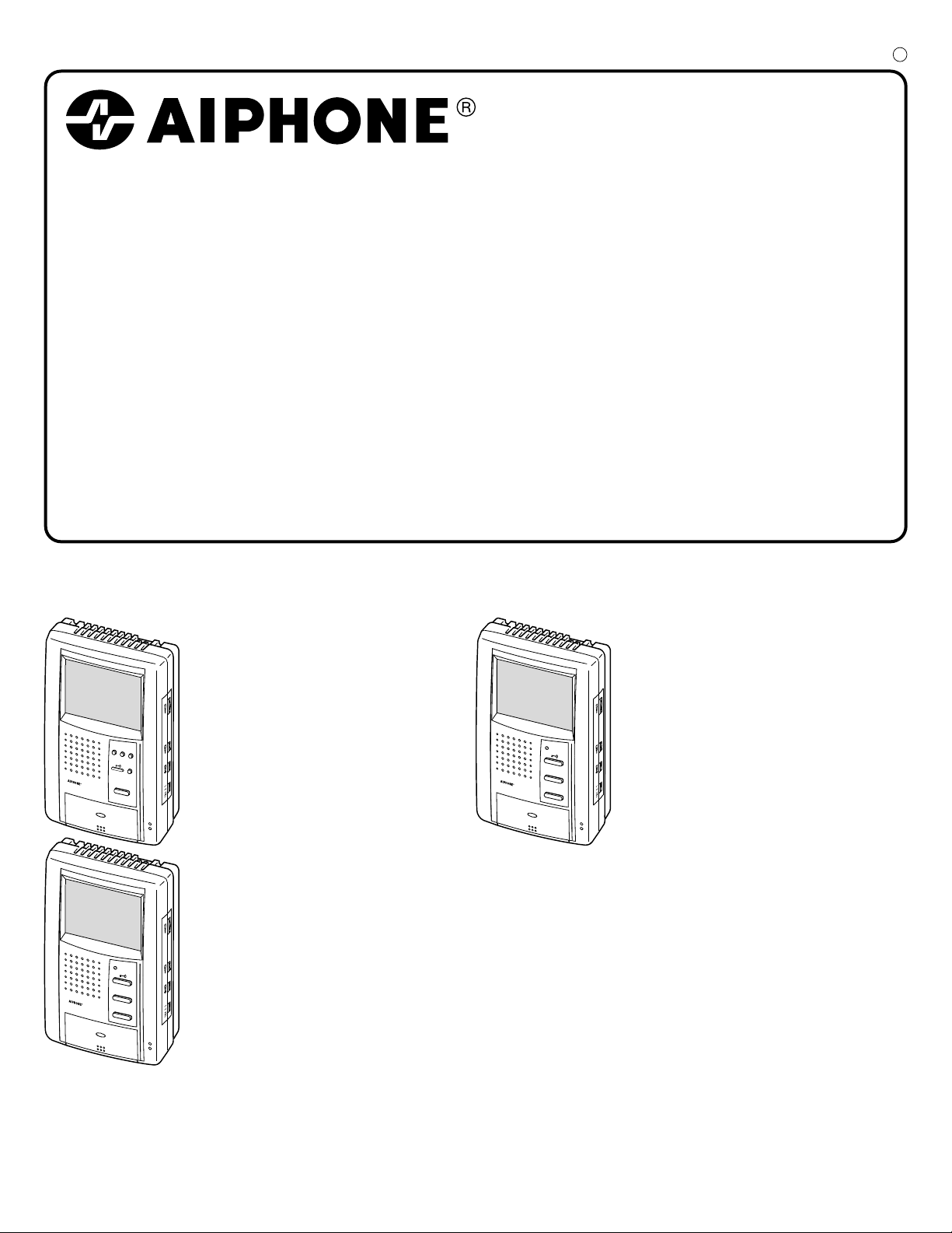
HANDSFREE COLOR VIDEO INTERCOM
JB-2MED
Master monitor station (w/ built-in picture memory)
JB-2MD
Master monitor station
JB-2HD
Sub monitor station
- 1 -
INSTALLATION & OPERATION MANUAL
Page 2
PRECAUTIONS
English
General Prohibitions Prohibition to Dismantle the Unit
1 2 3 4
5 6
+ 5 cm
(2")
+ 5 cm
(2")
JB-2MED
JB-2MD
1
2
Prohibition on Subjecting the Unit to Water General Precautions
WARNING
(Negligence could result in death or serious injury to people)
1. High voltage is present internally. Do not open the case. Electric shock could
result.
2. Do not dismantle or alter the unit. Fire or electric shock could result.
3. Do not connect any power source other than specified to terminals +,- nor install
two power supplies in parallel to single input. Fire or damage to the unit could
result.
4. Keep the unit away from water or any other liquid. Fire or electric shock could
result.
5. Do not put any metal into the unit through the openings. Fire or electric shock
could result.
6. When existing chime wiring is used, it is possible that it contains AC power. Unit
damage or electric shock could result. Ask a qualified electrician.
7. Do not puncture the LCD panel with a sharp-edged tool. Damage to the LCD panel
could occur, causing a liquid crystal spill. If liquid crystal makes contact with the
eyes or mouth, immediately wash away with water.
8. Do not put high pressure on the monitor cover. If fractured, injury could result.
9. Do not use a power supply with a voltage other than specified. Fire or electric
shock could result.
CAUTION
(Negligence could result in injury to people or damage to property)
1. Before turning on the power, make sure wires are not crossed or shorted. Fire or
electric shock could result.
2. Mount the unit onto the wall in a place where it cannot be easily jarred or bumped
by people. Injury could result.
3. Do not make any wiring connections while the power supply is turned on. Electric
shock or unit trouble could result.
4. Do not install or use the unit in any of the following places.
. Places in direct sunlight, or near heating equipment that varies in temperature.
*
. Places subject to metal particles, dust, oil, chemicals.
*
. Places subject to moisture and humidity extremes, such as bathrooms, cellars,
*
greenhouses, etc.
. Places where the temperature is quite low, such as inside a refrigerated area or in
*
front of an air-conditioner.
5. Do not cover the unit with a cloth, etc. Fire or unit trouble could result.
6. Use Aiphone Power Supply or specified one by Aiphone. If not used, it may be a
possible cause of fire or malfunction.
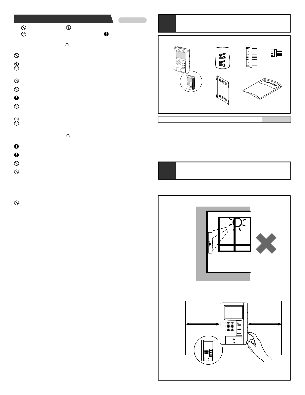
PACKAGE CONTENTS
1
Package contents
English
1. JB-2MD or JB-2MED or JB-2HD
2. Packet of screws
3. Connector for optional features
4. Door release connector (JB-2MD or JB-2MED only)
5. Mounting bracket
6. INSTALLATION & OPERATION MANUAL
INSTALLATION
2
2-1
1. This unit is for indoor use only. Do not use outdoors.
GENERAL PRECAUTIONS
2. When wall-mounted, the unit may become black and sooty. This does not indicate
unit trouble.
3. In areas where broadcasting station antennas are close by, the intercom system
may be affected by radio frequency interference.
4. The unit may become a little warm with use, but this is not a malfunction.
5. If a cellular phone is used close by, the unit may malfunction.
6. It must be noted in advance that the LCD panel, though manufactured with very
high precision techniques, inevitably will have a very small portion of its picture
elements always lit or not lit at all. This is not considered a unit malfunction.
7. Keep the unit more than 1 m away from Radio or TV set.
8. If the monitor station is operated near office equipment, radios or TVs, it will be
affected by radio wave interference or noise. Carefully select the place of use.
9. Ambient noise around the unit may prevent normal communication. This is not
unit trouble.
10.As to other manufacturer's devices, such as sensor, used with this system, comply
with the relative specifications and warranty conditions of the devices.
11.If the system is down or does not operate properly, turn off the unit power switches.
- 2 -
Page 3
Installation locations
JB-2MD JB-2HD
JA-2SDJB-2MED JA-2SD
JA-2SD
JB-2HDJB-DA
2 4 4
B1, B2
B1, B2
2
4
4
2
JB-DA
JB-DA
JB-2MD
JB-2MD
JB-2HD
JA-2SD
JA-2SD
JB-2HD
JA-2SD
JB-2HD
2
2
2
B1, B2
JB-2HD
4
8
4
JB-2MED
JB-2MED
JB-DA
JB-DV
JB-DVF
JB-2HD
A1A2B1
B2
A1
A2
B1
B2
+
-
+
-
B1
B2
A1
A2
(x2)
A1
A2
120 120
JB-2M(E)D
(JA-D)
D1
JB-2MD
JB-2HD
JB-2HD
PS
JB-DA
JB-DV
JB-DVF
PS-1820
PS-1810
IER-2
JA-D
D2
M
S1
S2
B
A A'
C D
JB-2MED
SP
JA-2SD
JA-2SD
English
1. Install the master monitor station in a place where the
screen is not exposed to direct sunlight.
2. The master monitor station has manual adjustment
switches on both sides. Secure an open space of 5 cm (2")
on either side of the monitor.
2-2
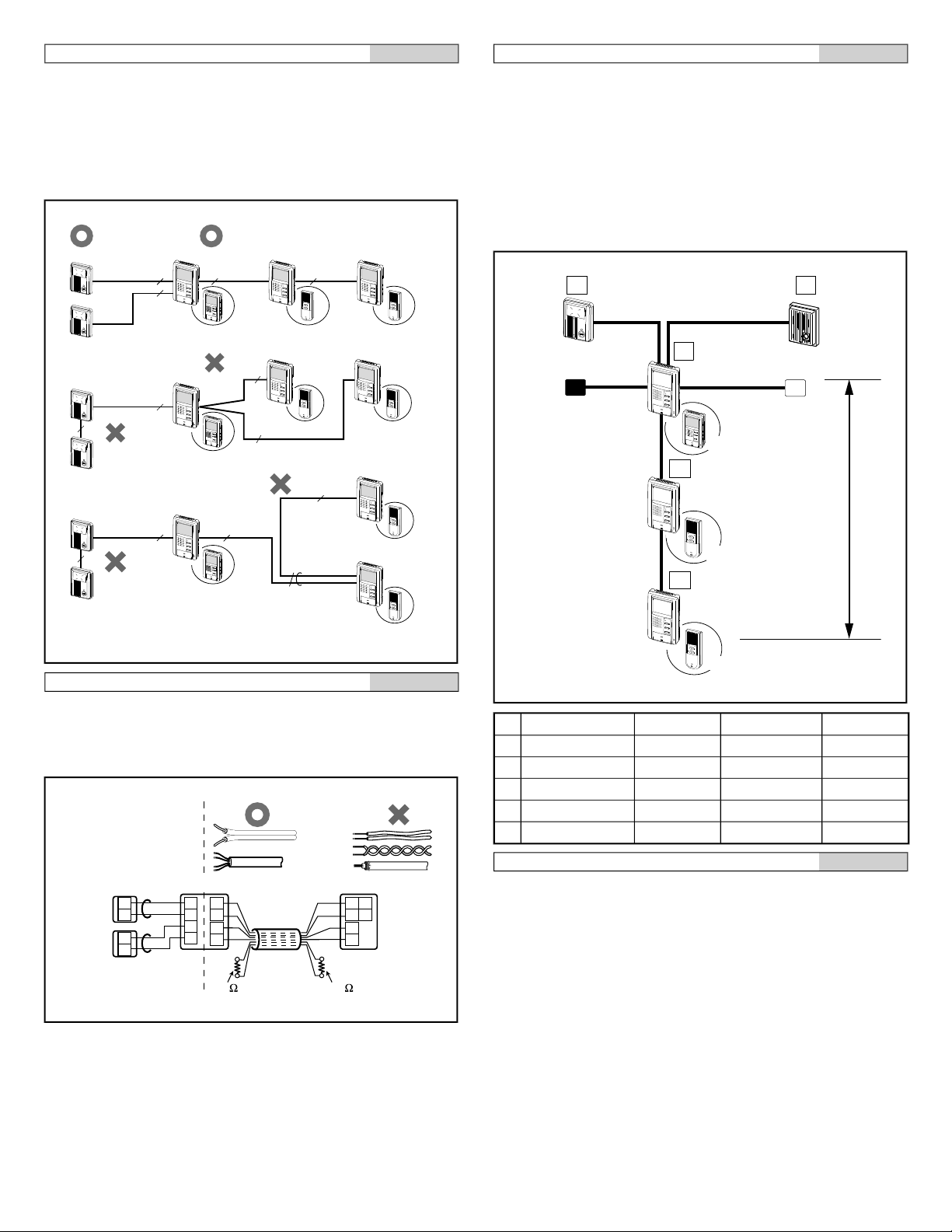
Cable
English
1. Parallel or jacketed 2-conductor, non-shielded cables are
recommended. PVC jacket with PE (polyethylene)
insulated conductors is recommended.
2. Do not use single loose wires, twisted pair cables or
coaxial cables.
3. When using a cable with unused wires, it is suggested that
both ends of unused pair(s) be terminated with a 120 Ω
resistor.
2-4
Wiring
English
Wire the inside stations in a daisy-chained fashion from the
master to the last sub monitor.
2-3
Ø 0,65 mm 22AWG Ø 1,0 mm 18AWG
A 50 m 165' 100 m 330'
A' 50 m 165' 100 m 330'
B 50 m 165' 100 m 330'
C 5 m 16' 10 m 33'
D 75 m 245' 150 m 490'
Wiring distance
NOTES: A Power Supply: PS-1810DIN covers 1(or 2) Door
station with One Monitor unit only.
- 3 -
English
Page 4
3
83,5 mm
(3-5/16")
[3][2][1]
[4]
83,5 mm
(3-5/16")
[3][2]
PS-1820DIN
PS-1810DIN
1
2
9mm
(3/8")
JB-2MD
TALK
JB-2MED
TALK
CALL
MONITOR
REC
PLAY
SET
JB-2MED
JB-2MD
JB-2HD
PS-1820
PS-1820S
PS-1820UL
#2
#1
E
SW
P
b2
b1
V -
V +
[2]
(BR)
(RD)
[5]
[6]
(OG)
(YE)
(RD)
(BR)
(OG)
(YE)
(GR)
(BL)
(PR)
[4]
[3]
[1]
#2 #1
#1
JB-2M(E)D
JB-2HD
c2
c1
L
L
PR: Violeta
BL: Azul
GR: Verde
YE: Amarillo
OR: Naranjo
RD: Rojo
BR: Marrón
PR: Paars
BL: Blauw
GR: Groen
YE: Geel
OR: Oranje
RD: Rood
BR: Bruin
PR: Lila
BL: Blau
GR: Grün
YE: Gelb
OR: Orange
RD: Rot
BR: Braun
PR: Violet
BL: Bleu
GR: Vert
YE: Jaune
OR: Orange
RD: Rouge
BR: Brun
PR: Purple
BL: Blue
GR: Green
YE: Yellow
OR: Orange
RD: Red
BR: Brown
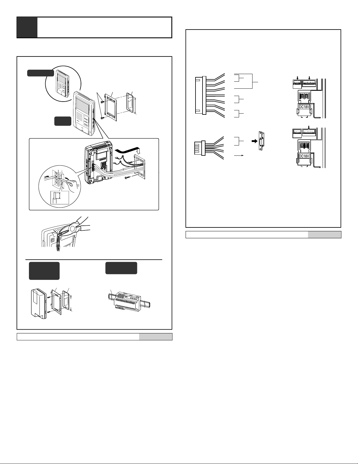
3-1
MOUNTING
3-2
Mounting
[1] Screws (x2)
[2] Mounting bracket
[3] 1-gang box
[4] Din rail
1. Press the RELEASE button (to insert or remove the wire).
2. Insert the cable into the terminal.
NOTES: When a 1-gang box is not installed, the cable can
be surface-run to the top or bottom of the unit. Cut
the cable inlet to allow passage of the wiring into
the unit.
English
Options
[1] Foot switch
Connect a locally available pedal foot switch to PURPLE
and BLUE wires (dry closure contact).
[2] Manual Press-to-Talk restriction
Short PURPLE and GREEN wires together to prevent
manual TALK button operation.
[3] Selective door release
Please refer to the wiring diagram #9 for detail
connection.
[4] Video output to video monitor, video switcher, etc.
(NTSC,1 Vp-p/75Ω)
[5] Single door release
Connect BROWN and RED wires from connector #2 to a
single door release (or to the RY-3DL as shown on the
wiring diagram).
[6] Sensor (JB-2MED only)
NOTES: 1. For JB-2HD, only functions [1] and [2] are
available.
2. Cut off unused wires and insulate the ends to
prevent shorting.
3. Provide a box deep enough to accommodate all
cables including options.
- 4 -
English
Page 5
2
JB-2HD
2
JB-2HD
2'
JA-2SD
2'
JA-2SD
Set to OFF
when SUB OUT
is wired.
Set to OFF
when SUB OUT
is wired.
ON - OFF
ON - OFF
ON - OFF
ON - OFF
JB-2M(E)D JB-2HD
JA-2SD
ON
JB-2M(E)D JB-2HD
JA-2SD
OFF
JB-2HD
JA-2SD
ON
8
ON - OFF ON - OFF
1
JB-2M(E)D
RELEASE
A1
A2
A2
A1
B2
B1
S
S
5
PS-1820
PS-1820DIN
100V - 240V -
50/60 Hz
230 V AC
N
L
230V AC
N
L
18 V DC2A
18V DC
2 A
IN 230V~ 50/60Hz
NL
2A - +
+
PS-1810DIN
18V DC 1 A
IN 230V~ 50/60Hz
NL
1A - +
+
DC 18 V
-
+
2
OP
6
OP
10
PT
EL-9S
OP
IER-2
1
E
7
2
NP
2
NP
A1 A2A1 A2
AIPHONE
MK-DVF
3
JB-DVFJB-DV
MK-DV
AIPHONE
JB-DA
9
L1
C1
L2
C2
L1
L2
RY-3DL JB-2M(E)D
+
+
DC18 V
EL-9S
b1
b2
b3
D1
D2
E
EL-9S
PS18
YE(b2)
OG(b1)
L
BR(L)
RD(L)
#1
#2
OG: Orange
YE: Yellow
BR: Brown
RD: Red
PT
4
JB-DVFJB-DV
AIPHONE
MK-DVF
MK-DV
AIPHONE
JB-DA
JA-D
SENSOR
2
-
+
-
+
-
+
4
4
2
2
NP
NP
OG: Orange
YE: Jaune
BR: Brune
RD: Rouge
OG: Orange
YE: Gelb
BR: Braun
RD: Rot
OG: Naranjo
YE: Amarillo
BR: Marrón
RD: Rojo
OG: Oranje
YE: Geel
BR: Bruin
RD: Rood
SUB IN
SUB OUT
B1
B2
B1
B2
SUB IN
SUB OUT
B1
B2
B1
B2
(JB-2MED)
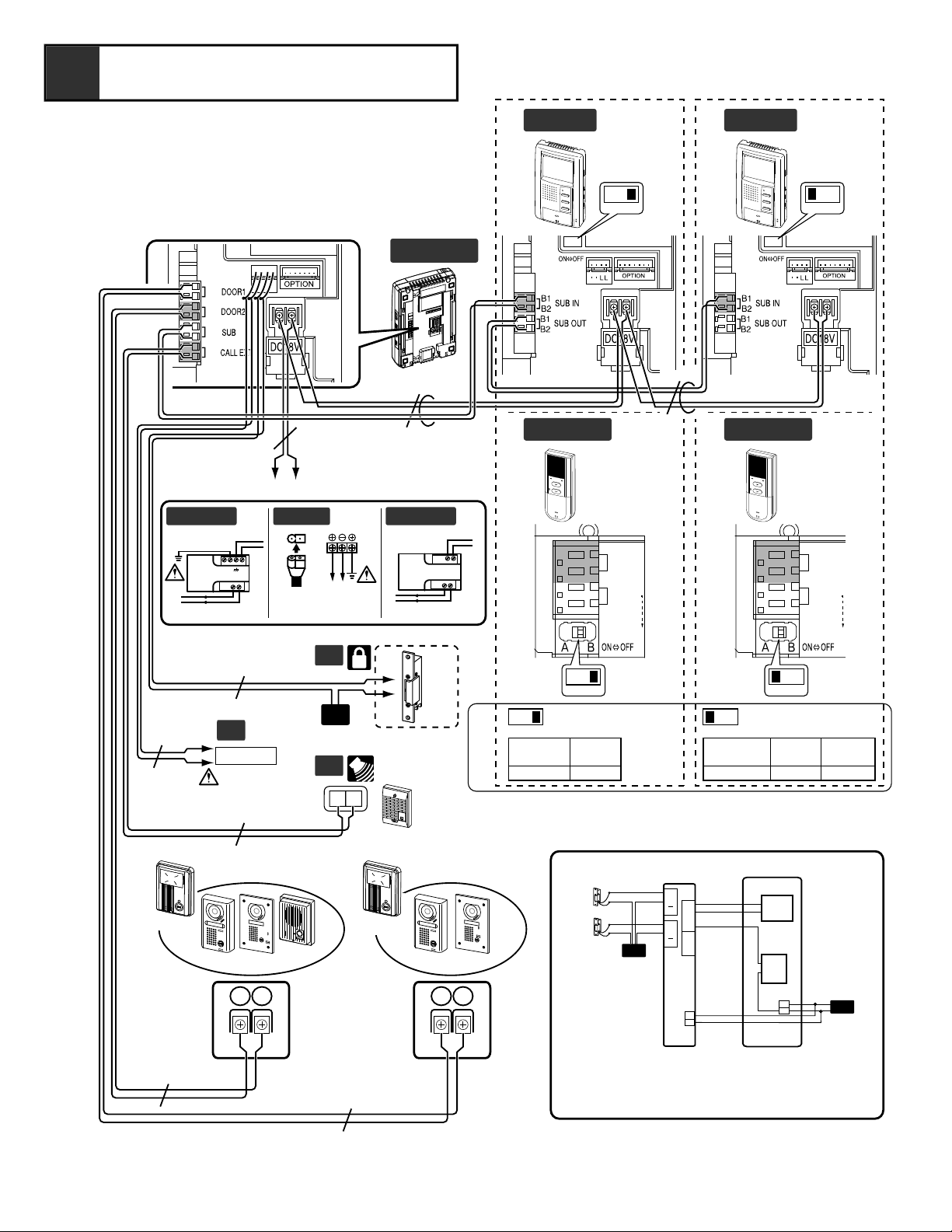
WIRING DIAGRAM
4
- 5 -
Page 6

Wiring
English
Securely insert wires into each terminal as shown.
1. Master monitor station JB-2MD or JB-2MED
2. Sub monitor station JB-2HD or sub station JA-2SD
3. Video entrance station
4. Video or audio entrance station
5. Power supply +, - (DC 18 V)
6. Optional door release EL-9S (AC 12 V, 0.35 A) or
equivalent, requires a separate AC transformer. Run
separate cables for the audio/video and door release.
Door release contact: AC/DC 24 V, 0.5 A (dry closure
contact L, L).
7. Optional call extension speaker IER-2
8. Impedance matching switch
Terminate farthest sub station by putting SW in ON
position. Otherwise both video and audio may become
distorted.
9. Optional selective door release adaptor RY-3DL Use RY3DL when connecting a door release for 2 locations.
10.Sensor (locally available)
Use outer equipment (sensor, etc) with dry-closure
contacts.
For details, please contact your local distributor.
.
JB-2MED only.
NP: Non-polarized
- 6 -
Page 7

[2]
[1]
[6]
[11]
[12]
[12] [13]
[13]
[14]
[7]
[8]
[9]
[10]
[4]
HIGHMUTED MID
LAUTLEISE MITTEL
FORTFAIBLE MOYEN
HIGHLOW MID
HOOGLAAG NORMAAL
FORTMUET MOYEN
LAUTAUS MITTEL
ALTOSILENCIO MEDIO
ALTOBAJO MEDIO
LUIDGEDEMPT GEWOON
JB-2MD , JB-2HD
JB-2MED
[3]
[5]
[2]
[1]
[7]
[8]
[16]
[17]
[15]
[9]
[10]
[4]
[3]
[5]
RCV.
[11]
BRIGHTDARK MID
LUMINEUXSOMBRE MOYEN
HELLDUNKEL MITTEL
BRILLANTEOBSCURO MEDIO
HELDERDONKER GEWOON
BRIGHT TONE
BRIGHTRCV.TONEDOOR CALL
[11]
[12]
[13]
[14]
BRIGHTRCV.TONEDOOR CALL
DOOR
CALL
MONITOR
TALK
JB-2MD
CALL
REC
MONITOR
TALK
JB-2MED
PLAYSET
JB-2MED
TALK
CALL
MONITOR
REC
PLAY
SET
SET PLAY REC
1
JB-2MED
31/DEC/04 23:45
31/DEC/04 23:45
31/DEC/04 23:45
31/DEC/04 23:45
PLAY REC
SET
2
3
31/DEC/04 23:45
PLAY REC
+
-
SET
ALARM (6S)
ALARM (30S)
PLAY REC
SET
PLAY REC
SET
4
16(4-FRAME IN
ONE PICTURE)
16
32
60
5
6
JB-2MED
TALK
CALL
MONITOR
REC
PLAY
SET
5
NAMES
SETTING UP
6
Names
[1] LCD (3-1/2" color)
[2] POWER switch
[3] Open voice speaker for chime and internal call-in voice
[4] Transmit LED
[5] TALK button
[6] Door call-in LED
[7] DOOR RELEASE button
[8] CALL button
[9] MONITOR button
[10] Mic.
[11] Screen brightness control
[12] Receive volume control
[13] Chime TONE volume control
[14] Door call-in selector switch
[15] SET button
[16] PLAY button
[17] REC button
English
- 7 -
Page 8

Setting up
21
4
3
JB-2MEDJB-2MD
21
4
3
5
JB-2MEDJB-2MD
1. If the record mode is changed in step 5, the previously
recorded screens are deleted. If you do not wish to
delete the screens, do not change the record mode.
2. If you only want to change a certain item, or if you made
a mistake in the settings, you must go through the entire
sequence. Start again from "Mode selection".
3. The setting mode will end automatically after 2-1/2
minutes. If it ends during setting, start again from "Mode
selection".
• If the SET button is flashing or is on before starting, turn it
off with the following method.
• If it is flashing: Press the PLAY button. When play is
complete, press the SET button.
• If it is on: Press the SET button.
1. Mode selection:
Press the SET button for 2 seconds or more to select the
setting mode.
2. Setting the position of the date/time display:
Press the PLAY button to move upward, and the REC
button to move downward, and set with the SET button.
3. Setting the date/time:
Use the PLAY button (+) and the REC button (-) to adjust
the sequence of year _ month _ date _ hour _ minute, and
set with the SET button.
4. Setting the alarm time:
Select with the PLAY button to move upward, and the REC
button to move downward, and set with the SET button.
5. Setting record mode:
Select the number of pictures to be saved. Press PLAY
button tomove upward, and the REC button to move
downward. Set with the SET button.
6. End:
Press the TALK button to end the setting process during
steps 1 to 5. Otherwise, it will end automatically after 2-1/
2 minutes.
English
Answering a door call (Voice actuate mode)
1. The CALL button of the entrance station is pressed.
2. The chime tone sounds, the caller is seen on the video
monitor, and the caller's voice is heard.
3. Press the TALK button momentarily, then communicate
handsfree. The transmit LED lights when you talk, and
goes off as you listen to the caller (or hear outside sounds).
4. Press the TALK button again to end.
NOTES: 1. In step 2, the video and audio go off after approx.
45 seconds. If the TALK button is pressed within
approx. 45 sec., it connects to the caller's
entrance station.
2. In step 2, the door call-in LED on the JB-2MD
and JB-2HD lights in red if called from entrance
station 1, and in green if called from entrance
station 2.
3. If there is a lot of noise at the entrance station
and conversation is difficult, use the MANUAL
Push-to-Talk mode.
4. Communication (video) ends automatically after
approx. 1 minute. If the TALK button is pressed
within approx. 30 sec., it connects again to the
caller's entrance station.
5. If a call is received from an entrance station
while already responding to another station, a
chime tone sounds only at the master station
where communication is taking place. Quickly
finish communicating with the first calling
entrance station. Press the TALK button again
to start communication with the other calling
entrance station.
6. If it turns to dark in the evening, LEDs in the door
station light on automatically.
English
7-2
OPERATIONS
7
7-1
- 8 -
Page 9

Answering a door call (MANUAL mode)
21
JB-2MEDJB-2MD
JB-2MEDJB-2MD
CALL
MONITOR
CALL
MONITOR
SET PLAY REC
21
JB-2MEDJB-2MD
21
43
JB-2MEDJB-2MD
JB-2MEDJB-2MD
CALL
MONITOR
CALL
MONITOR
SET PLAY REC
1
3
2
JB-2MED
TALK
CALL
MONITOR
REC
PLAY
SET
4
JB-2MEDJB-2MD
JB-2MEDJB-2MD
CALL
MONITOR
CALL
MONITOR
SET PLAY REC
English
NOTES: 1. In step 2, the video and audio go off after approx.
45 seconds. If the TALK button is pressed within
approx. 45 sec., it connects to the caller's
entrance station.
2. In step 2, the door call-in LED of the JB-2MD
and JB-2HD lights in red if called from entrance
station 1, and in green if called from entrance
station 2.
3. If you press the TALK button in step 4 for a short
time (less than 2 sec.), communication will end.
4. Communication (video) ends automatically after
approx. 1 minute. If the TALK button is pressed
within approx. 30 sec., it connects again to the
caller's entrance station.
1. The CALL button of the entrance station is pressed.
2. The chime tone sounds, the caller is seen on the video
monitor, and the caller's voice is heard.
3. Press and hold the TALK button for 2 seconds or more.
4. Keep pressing the TALK button to talk, and release to
listen to the caller.
5. Press the TALK button momentarily (less than 2 sec.) to
end.
7-3
Instant voice call function
1. The CALL button of the entrance station is pressed.
2. Even without answering, the door area can be seen and
heard with video and audio (for approx. 45 sec.). Inside
sound is not heard outside.
NOTES: JA-D does not have this function. Audio is only
established when the call is answered.
English
7-5
Entrance monitoring
1. Press the MONITOR button.
2. The video monitor displays the image of entrance station
1 and the audio is heard. If you do not press the TALK
button, the caller will not hear your voice.
3. Press the entrance MONITOR button again to switch to
entrance station 2. If a JA-D (audio only) unit is connected
to entrance 2, it is skipped (cannot be monitored).
4. Press the MONITOR button again to end.
NOTES: 1. To talk to the entrance station during monitoring,
press and release the TALK button. Press the
TALK button again to end the communication.
2. The entrance monitoring ends automatically
after approx. 1 min. To monitor the entrance
again, repeat from step 1.
3. If a call is received from another entrance station
during monitoring, it switches to the calling
station.
English
7-6
7-4
Activating door release
1. Press the DOOR RELEASE button in communication or
2. The door is unlocked.
monitoring.
English
- 9 -
Page 10

Room-to-room communication
1
3
2
JB-2MED
TALK
CALL
MONITOR
REC
PLAY
SET
JB-2MED
TALK
CALL
MONITOR
REC
PLAY
SET
4
JB-2MED
TALK
CALL
MONITOR
REC
PLAY
SET
JB-2MED
TALK
CALL
MONITOR
REC
PLAY
SET
JB-2MEDJB-2MD
JB-2MEDJB-2MD
CALL
MONITOR
CALL
MONITOR
SET PLAY REC
01/APR/04 15:30
16-picture, 4-frame mode 16/32/60-picture mode
6 sec.2 sec.
14 sec.10 sec.
2 sec.
01/APR/04 15:30
JB-2MED
SET PLAY REC
JB-2MED
TALK
CALL
MONITOR
REC
PLAY
SET
JB-2MED
TALK
CALL
MONITOR
REC
PLAY
SET
JB-2MED
English
1. Press the CALL button once.
2. The "All Call" function is activated to link all of the inside
stations.
3. If another person presses the TALK button, handsfree
communication is possible.
4. Press and release the TALK button to end.
.
Do not press the TALK button during communication in
step 3. It will end the communication.
NOTES: 1. Room-to-room communication ends
automatically after approx. 1 minute.
To have another room-to-room conversation,
repeat from step 1.
2. If a call is received from an entrance station
during room-to-room communication, a chime
tone sounds only at the master station where
communication is taking place. Quickly end
room-to-room communication, then the system
switches to the calling entrance station.
7-7
7-8
Automatic recording
If a call is received from the entrance, the unit starts
recording automatically. The REC button lights during
recording.
• 16-picture/4-frame mode: Records at approx. 2 sec., 6 sec.,
10 sec. and 14 sec. from time of call-in.
• 16/32/60-picture mode: Records after approx. 2 sec.
NOTES: 1. The automatic recording function cannot be
cancelled.
2. The screen shown when monitoring the
entrance is not recorded automatically. If you
wish to record this screen, press REC button.
3. When automatic recording has finished, for
approx. 15 sec. after the monitor screen goes
off, automatic recording will not be activated for
the same entrance station even if a call is placed
(to prevent prank calls).
English
Transfer entrance call
1. Press the CALL button during communication with an
entrance station.
2. An image of the entrance is displayed on all of the monitor
stations.
3. If the transferred station presses the TALK button, roomto-room communication starts.
4. If the transferred station presses the TALK button again, it
switches to entrance station calling mode. By pressing the
TALK button once more, communication is established
with the entrance station. To end, press and release the
TALK button.
NOTES: 1. The call-in from the entrance station will be held
for 45 seconds. End the room-to-room
communication within this timeframe.
2. Communication ends automatically after
approx. 1 min.
English
7-9
Manual recording
1. Display a video image with the entrance MONITOR button.
2. Press the REC button. The REC button lights and
recording starts.
NOTES: 1. Even if 16-picture/4-frame mode is selected,
only 1 frame is recorded in manual mode.
2. If manual recording is activated when a call is
received from an entrance station, it overwrites
the automatically recorded image.
- 10 -
English
Page 11

7-10
JB-2MED
TALK
CALL
MONITOR
REC
PLAY
SET
01/APR/04 14:30
SETSET
2/5
1
3
2
2/5
JB-2MED
TALK
CALL
MONITOR
REC
PLAY
SET
SET SET
JB-2MED
29/MAR/04 20:03
30/MAR/04 09:48
30/MAR/04 20:25
01/APR/04 15:30
01/APR/04 17:15
[1] [2] [3]
JB-2MED
01/APR/04 14:30
16-picture, 4-frame mode
16/32/60-picture mode
JB-2MED
TALK
CALL
MONITOR
REC
PLAY
SET
JB-2MED
TALK
CALL
MONITOR
REC
PLAY
SET
PLAY
REC
1
2
3
01/APR/04 14:30 01/APR/04 13:25 01/APR/04 10:18
01/APR/04 14:30
JB-2MED
7-12
Absence set (Auto absence recording)
English
1. If the SET button is pressed once (less than 2 sec.), it will
light and the unit will be set.
2. If the absence set (auto absence recording) is operating,
the SET button flashes to show that there has been a caller
(if the image is played, it goes back to being lit). When the
image is played, the number of callers who came while you
were out is displayed. Example: 2/5" means Second image
from a total of 5.
3. Press the SET button again to cancel. The SET button light
will go off.
.
In step 1, if pressed and held for more than 2 sec., it will
enter setting mode.
NOTES: Cancellation in step 3 is not possible while the SET
button is flashing. First play the recorded screen.
7-11
Play
English
1. Press the PLAY button to view the newest picture.
2. Each time the PLAY button is pressed, it moves to the next
picture that was previously recorded. After the final picture,
it becomes a blue screen before returning to the first
picture. Press the REC button to reverse the selection
direction.
3. Press the TALK button to end. It ends automatically
approx. 1 min. after the final operation.
1. In step 1, playback is not possible if there are no
recorded pictures.
2. In 16-picture/4-frame mode, the REC button in step 2 is
used to view each picture in a full-screen view.
Automatic updating function for recorded screens
If the number of recorded pictures exceeds the maximum
number set for recording mode, the oldest picture is
automatically replaced with the new picture (pictures are
erased even if they have not been played).
[1] Adding new picture
[2] Number of pictures set for recording mode
[3] Erasing the earliest taken picture
NOTES: You can save pictures that you want to keep. (P23)
English
- 11 -
Page 12

7-13
01/APR/04 15:30
1
2
3
4
PLAY
REC
REC
01/APR/04 15:3001/APR/04 15:30
01/APR/04 15:3001/APR/04 15:30
JB-2MED
TALK
CALL
MONITOR
REC
PLAY
SET
01/APR/04 15:30
01/APR/04 10:18
01/APR/04 13:25
01/APR/04 15:30
01/APR/04 15:30
JB-2MED
1
2
SET
SET
M5
01/APR/04
M5
JB-2MED
01/APR/04
01/APR/04 14:30
01/APR/04 14:30
FULL
1
2
SET REC
01/APR/04 14:30
JB-2MED
01/APR/04 16:00
7-14
Sub screen enlargement (16-picture/4-frame mode only)
1. If the REC button is pressed when playing a 4-frame
picture (P21), the last picture (taken after 14 sec.) is
enlarged.
2. Press the REC button again to enlarge the previous sub
screen (after 10 sec.). Repeat in sequence for the other
sub screens. After the end of sub screen enlargement, it
returns to the 4-frame screen.
3. Press the PLAY button to display the next previously
recorded picture (in 4-frame mode).
4. Press the TALK button to end. It ends automatically
approx. 1 minute after the final operation.
.
In 16-picture/4-frame mode, the selection sequence
cannot be reversed. Pictures recorded manually (not
divided into 4 frames) cannot be enlarged.
English
Save
English
1. Press the SET button during play (P21) to save the picture.
"M" is displayed to show it has been saved, and the
number of the saved pictures is also displayed. A
maximum of 8 pictures can be saved.
Example: "M5" means that 5 pictures have been saved.
2. Press the SET button when playing a saved picture to
cancel the saving function and delete the "M".
NOTES: 1. If SAVE is operated during the playing of an
individual picture in the 4-frame mode, all of the
4 pictures are saved on a single screen.
2. If you try to save a ninth picture, "FULL" will be
displayed in the middle of the screen.
3. In step 2, the saving function is cancelled, but
the picture itself is not erased. However it will be
overwritten (erased) if a new picture is recorded.
4. Saved pictures cannot be overwritten by other
operations, except the erase function. (P24)
7-15
- 12 -
Page 13

Erase
Prrrrrrrr
1. Use the play operation to display the picture you wish to
erase. (P21)
Push the SET button and REC button simultaneously for
2 sec. to erase.
2. The picture to be erased is deleted, and the next picture
will be displayed. When the next picture is displayed, let
go of the button.
1. Erase operations will also erase saved pictures.
2. Once a picture is erased, it cannot be restored.
3. It is not possible to delete only a single sub screen of a
4-frame picture recorded in 16-picture/4-frame mode.
4. To erase all of the pictures, change recording mode in
the settings. This will erase all of the pictures recorded
up to that point. (P11)
SURVEILLANCE SETTING
8
English
TECHNICAL PRECAUTIONS
9
Technical precautions
• Operating temperature: 0 °C to 40 °C (+32 °F to +104 °F)
• After the unit is not used for a long time or after an extended
power failure (approx. 30 min. or more), if both the PLAY
and REC buttons light at the same time, perform the record
function settings again. (P11)
• The video image may distort when the DOOR RELEASE
button is pressed. This is not a unit malfunction.
• Cleaning: Clean the units with a soft cloth dampened with a
neutral household cleanser. Do not use an abrasive cleaner
or cloth.
• The entrance station is weather-resistant. However, do not
spray it directly with high-pressure water. Unit trouble could
result.
• If there is a system malfunction, turn the power switch at the
master station off and back ON again. If this does not solve
the problem, unplug the DC power supply and contact a
qualified technician for service.
English
If a sensor light is installed (local product)
1. If something is detected by the sensor (locally available
product), an alarm goes off with a sound and a warning
screen. If more than 1 min. has passed after the absence
set (auto absence recording) was set, motion detection will
be in operation.
2. Press the TALK button to restore. (Automatic restoration
after approx. 30 sec.)
1. JB-2MED only.
2. Read the instruction manual for the sensor light (local
product), or contact your local installer or dealer.
NOTES: 1. In step 1, the length of time that the alarm
sounds can be changed. (P11)
2. Press the TALK button to stop the alarm and
warning screen.
3. Communication with the sensor light is not
possible.
4. If the absence set (auto absence recording) is
cancelled, the sensor light does not call the unit,
but the sensor light continues with its
surveillance function.
5. In calling and communication, sensored
alarming sound does not come out.
6. Also the alarming sound does not come out
through Sub room master station(s).
English
10
Specifications
• Power:
• Current consumption:
• Calling:
• Communication:
• Video monitor:
• Scanning lines:
• Door release contact:
• Dimensions:
• Weight:
SPECIFICATIONS
English
DC 18 V(JB-2MED, JB-2MD, JB2HD).
(Max.) 770mA (JB-2MED)
(Max.) 670 mA (JB-2MD)
(Max.) 250 mA (JB-2HD)
Chime and image, approx. 45
sec.
(AUTO) Handsfree, approx. 60
sec.
(MANUAL) Press to talk, release
to listen, approx. 60 sec.
3-1/2 " direct view TFT color LCD.
525 lines.
Door release contact: AC/DC 24
V, 0.5 A (dry closure contact L, L).
(Aiphone's EL-9S is
recommended.)
175(H) x 115(W) x 43(D) (mm).
6-7/8 " H x 4-7/32 " W x 1-11/16 "
D
Approx. 430 g (0.95 lbs.) (JB2MED)
Approx. 400 g (0.9 lbs.) (JB-2MD,
JB-2HD)
- 13 -
Page 14

WARRANTY
English
Aiphone warrants its products to be free from defects of material and
workmanship under normal use and service for a period of two years after
delivery to the ultimate user and will repair free of charge or replace at no
charge, should it become defective upon which examination shall disclose
to be defective and under warranty. Aiphone reserves unto itself the sole
right to make the final decision whether there is a defect in materials and/
or workmanship; and whether or not the product is within the warranty.
This warranty shall not apply to any Aiphone product which has been
subject to misuse, neglect, accident, or to use in violation of instructions
furnished, nor extended to units which have been repaired or altered outside
of the factory. This warranty does not cover batteries or damage caused by
batteries used in connection with the unit. This warranty covers bench
repairs only, and any repairs must be made at the shop or place designated
in writing by Aiphone. Aiphone will not be responsible for any costs
incurred involving on site service calls.
This equipment has been tested and found to comply with the limits for a
Class B digital device, pursuant to Part 15 of the FCC Rules. These limits
are designed to provide reasonable protection against harmful interference
in a residential installation. This equipment generates, uses, and can radiate
radio frequency energy, and if not installed and used in accordance with the
instructions, may cause harmful interference to radio communications.
However, there is no guarantee that interference will not occur in a
particular installation. If this equipment does cause harmful interference to
radio or television reception, which can be determined by turning the
equipment off and on, the user is encouraged to try to correct the
interference by one or more of the following measures: •Reorient or relocate
the receiving antenna•Connect the equipment into an outlet on a circuit
different from that to which the receiver is connected. Increase the
separation between the equipment and receiver.•Consult the dealer or an
experienced radio/TV technician for help.
AIPHONE CO., LTD., NAGOYA, JAPANAIPHONE CORPORATION, BELLEVUE,
- 14 -
WA, USAAIPHONE S.A.S., WISSOUS CEDEX, FRANCE
Printed In Japan
http://www.aiphone.com/
 Loading...