

Page 1
Hydraulic Seed Control
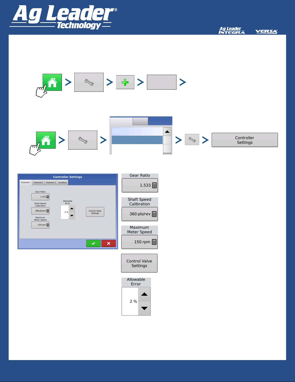
To create a conguration, make the following button presses to start the Conguration Wizard and then follow
the instructions given on the display.
Enter Settings
Conguration Product
Planting
Press to Highlight Conguration
8360,1770,3dr
Planting
The number of times the hydraulic drive sprocket turns
to achieve 1 revolution of the seed meter. Use the
formula in the examples on page 2 to calculate Gear
Ratio. Carry the decimal to the nearest 0.0001.
The number of encoder pulses per revolution of the
hydraulic drive motor.
Start of Conguration Wizard
Maximum RPM of the seed meter
Adjusts settings based on control valve characteristics.
Explained on page 3.
Percent error that is allowed before the hydraulic drive
changes rate.
Quick Reference Guide
2006004-ENG Rev A
1
Page 2
Hydraulic Seed Control
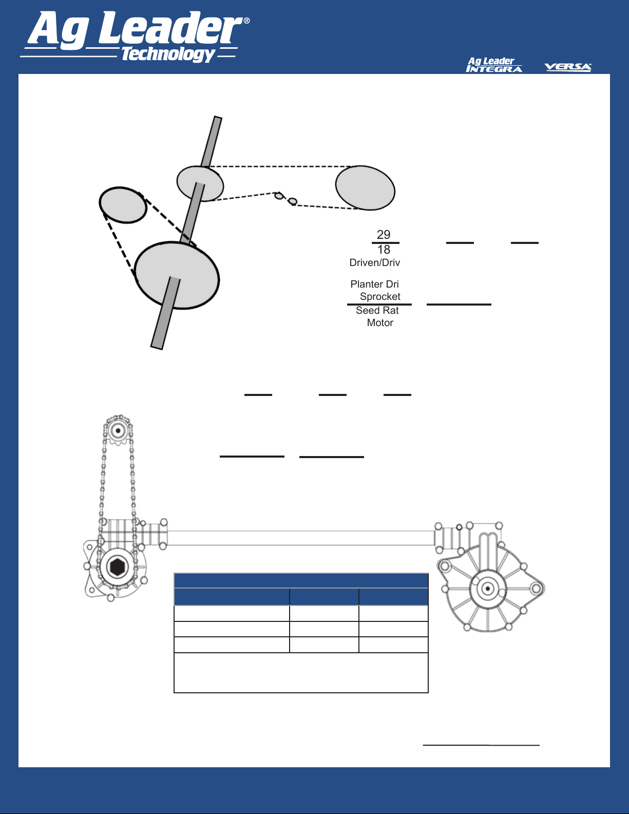
Calculating Gear Ratio
Planter Drive Shaft
Sprocket (Drive)
19-tooth sprocket
Seed Rate
Motor (Drive)
18-tooth
sprocket
Drive
Ratio 1
Planter Drive Shaft
Sprocket (Driven)
29-tooth sprocket
Figure 1: Calculating gear ratio of chain drive meters.
Seed Rate Motor
(Drive) 18 Tooth
Sprocket
29 28 812
18 19 342
Driven/Drive 1 X Driven/Drive 2 = Gear Ratio
Drive
Ratio 2
X
Planter Drive Shaft
Sprocket (Driven)
28-tooth sprocket
29 28 812
18 19 342
Driven/Drive 1 X Driven/Drive 2 = Gear Ratio
Planter Drive
Sprocket
Seed Rate
Motor
X
Seed Meter
Shaft
X
Planter Drive
Shaft
2.3743
==
Gear Ratio
=
2.3743
==
Seed Meter
Shaft
X
Planter Drive
Shaft
Drive Ratio 2
Gear Ratio
=
Planter Drive Shaft
Sprocket (Driven/
Output) 28 Tooth
Sprocket
Drive
Ratio
1
Planter Drive
Sprocket
Seed Rate
Planter Drive
Shaft Sprocket
(Drive/Input) 19
Tooth Sprocket
Motor
Drive Ratio 2
Planter Brand Driven Drive
Planter Drive
Figure 2: Calculating gear ratio of shaft drive meters.
If determining shaft ratios for any shaft not listed in the table above, rotate input shaft (driver) 10 times. Count how many
times the output (driven) shaft turns. Divide number of turns of the input shaft by the number of turns of the output shaft.
Shaft Sprocket
(Driven) 29 Tooth
Sprocket
Case IH Planters 2 1
John Deere Planters 3 2
White Planters 11 5
Note: These values are for the shaft only. Drive/Driven
value between the Seed Rate Motor and Planter
Drive Sprocket must still be determined.
Divide number of turns of the input shaft by the number of turns of the output shaft.
Quick Reference Guide
2006004-ENG Rev A
input shaft revolutions
output shaft revolutions
2
Page 3

Hydraulic Seed Control
Control Valve - PWM
Too low - seeding rate is slow to get on target at the beginning of a pass.
Too high - seeding rate will be too high at slower travel speeds.
Hydraulic Seed Meter Calibration Numbers
Signal pulses per second (Hz)
being sent to valve. The correct
setting is dened by the valve
manufacturer.
Aggressiveness of rate change
adjustments. Higher values will
respond more aggressively.
Maximum duty cycle that can be
sent to valve without producing
any ow.
Planter Brand
Control Valve
Conguration
John Deere Planters
White Planters PWM 200 90 30 5.5 360
Case IH Planters PWM 100 90 40 6.803 360
Prior to calibrating the Hydraulic Seed Meter, the numbers that appear in the Meter Calibration box in the Planter Control window should be similar
to the numbers that appear above. If they are not, the seed meter may be working incorrectly or the Gear Ratio may be incorrect. Contact Technical
Support for further assistance.
PWM 175 110 40 2.374 (chain)
PWM Frequency
Controller Settings - Auxiliary tab
PWM Gain
Amount of time that a seed rate error must occur
before alarm is triggered
Percentage of seed rate error that triggers an alarm
Zero Flow Offset
Gear Ratio
2.417 (ProShaft)
Pulsed/
Revolution
360
The planter will plant at this simulated ground speed, until displayed ground speed is above this value.
Planting at the minimum ground speed will occur when any of the following conditions are met:
a) Ground speed is less than the above setting
b) Wheel motion is detected. Requires wheel motion sensor
c) Jump start switch is depressed. Requires jump start switch kit
Quick Reference Guide
2006004-ENG Rev A
3
Page 4

Hydraulic Seed Control
Product Control Toolbox
gal/ac
1
2
Target Rate #1 & #2
preset planting rates that allow a quick change between rates
Manual Valve Control
allows operator manual control of seed meters
Prescription
allows planting rates to be determined by a loaded prescription
Target Rate
desired amount of product to apply
Actual Rate
actual rate of product being applied as determined
by the ow sensor
Up and Down Arrows
allow planting rates to be adjusted manually
Settings button
opens Rate Control Settings screen
Quick Reference Guide
2006004-ENG Rev A
4
 Loading...