

Page 1

Hydraulic Downforce
To create a conguration, make the following button presses to start the Conguration Wizard and then follow the
instructions given on the display.
Enter Settings
Planting
Conguration Product
Planting
Press to Highlight Conguration
8360,1770,3dr
Gauge Wheel Load Alarm
Start of Conguration Wizard
Down
Force
Select planter type (drop down menu)
If using uplift springs, enter value as dened
in installation instructions
Places an upper limit on the amount of
supplemental down force
Alarm will trigger if any monitored gauge wheel
load is below this value for a duration of time
Alarm will trigger if any monitored gauge wheel
load is below Minimum Load for this amount of
time
Down Force Control Mode (drop down menu)
Monitor Only: Select this option if only using gauge wheel sensors in conjunction with other
supplemental down force products (i.e. manually adjusted springs or airbags)
Control: Select this option is using Ag Leader hydraulic down force actuator and gauge
Control Settings
Note: Some planters may have a combination of long and short parallel arms depending on accessories. In this case use
the value that represents the majority of the rows.
wheel sensors. This option allows for active down force control
Enabling this option will disengage active control (hold) when any portion of the planter enters
a no plant zone, such as boundaries, or previously planted areas. Use caution with this option if
planting long point rows. Alarms are disabled when system is in hold.
Value must be entered for your specic planter and parallel arm combination
Kinze 3000 series 4.2 PSI/lb
John Deere Max Emerge/XP with short parallel arms
John Deere Max Emerge/XP with long parallel arms 3.8 PSI/lb
4.5 PSI/lb
Quick Reference Guide
AL: 2006350 ENG Rev B
1
Page 2
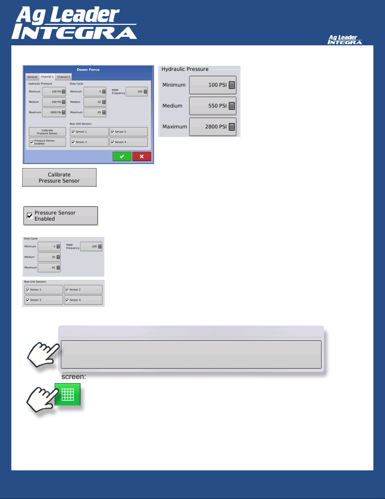
Hydraulic Downforce
Manually entered values depicting
tractor’s hydraulic pressure. Values shown
are for a 3000 PSI system (most common)
Select Channel to Calibrate
1. Set Point: Enter value here that matches value displayed on the corresponding channel’s
mechanical gauge attached to Ag Leader Down Force valve. (This can be done at 0 PSI)
2. Slope: value is dependent on manufacture of pressure transducer. Use 0.75 PSI/mV for
transducer supplied with valve.
Pressure Sensor Enabled: must be enabled to display “Down Force” on run screen.
Duty Cycle
Minimum/Medium/Maximum: Manually entered values correlating PWM duty cycle to
hydraulic pressure supplied to Down Force actuators. Values shown are for the Ag
Leader supplied hydraulic down force valve.
PWM Frequency: Number of PWM signals per second (Hz)
Row Unit Sensors
Enabled sensors will be used to calculate required supplemental down force
To start the Field Operation Wizard and load a conguration:
Conguration
To view run screen:
Quick Reference Guide
Start Field Operation
AL: 2006350 ENG Rev B
2
Page 3
Hydraulic Downforce
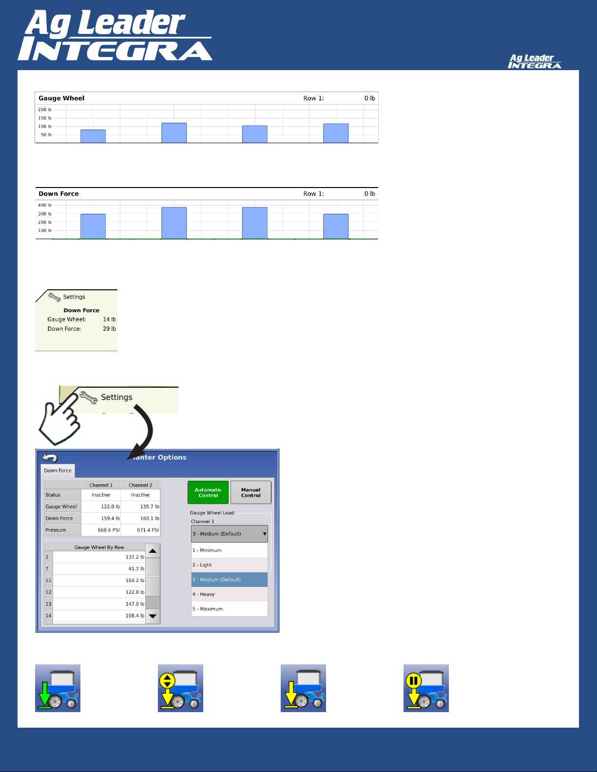
Gauge Wheel (bar graph): Each bar displays gauge wheel load for monitored rows
Down Force (bar graph): Each bar displays supplemental down force for monitored
rows
Down Force
a. Gauge Wheel: Planter average gauge wheel load
b. Down Force: Planter average supplemental down force
Planter Options - Down Force tab
Status: displays current status of control system
Active: System is actively controlling down force
Inactive: System is not actively controlling down force
Hold: Pressure is being held constant due to manual hold or
automatic hold
Gauge Wheel: Instantaneous channel average gauge wheel
load
Down Force: Instantaneous hydraulic pressure
Pressure: Pressure reading from corresponding channel
pressure transducer
Gauge Wheel By Row (table): Instantaneous gauge wheel load
for each monitored row
Automatic Control (button): Active down force control mode.
Gauge Wheel Load: User selected aggressiveness. Higher
aggressiveness will equate to higher gauge wheel loads
Manual Control (button): Allows user to manually adjust
pressure supplied to down force actuators across planter. Active
down force is disabled when in this mode.
Active Manual Inactive Manual
Hold
Quick Reference Guide
AL: 2006350 ENG Rev B
3
Page 4
Hydraulic Downforce
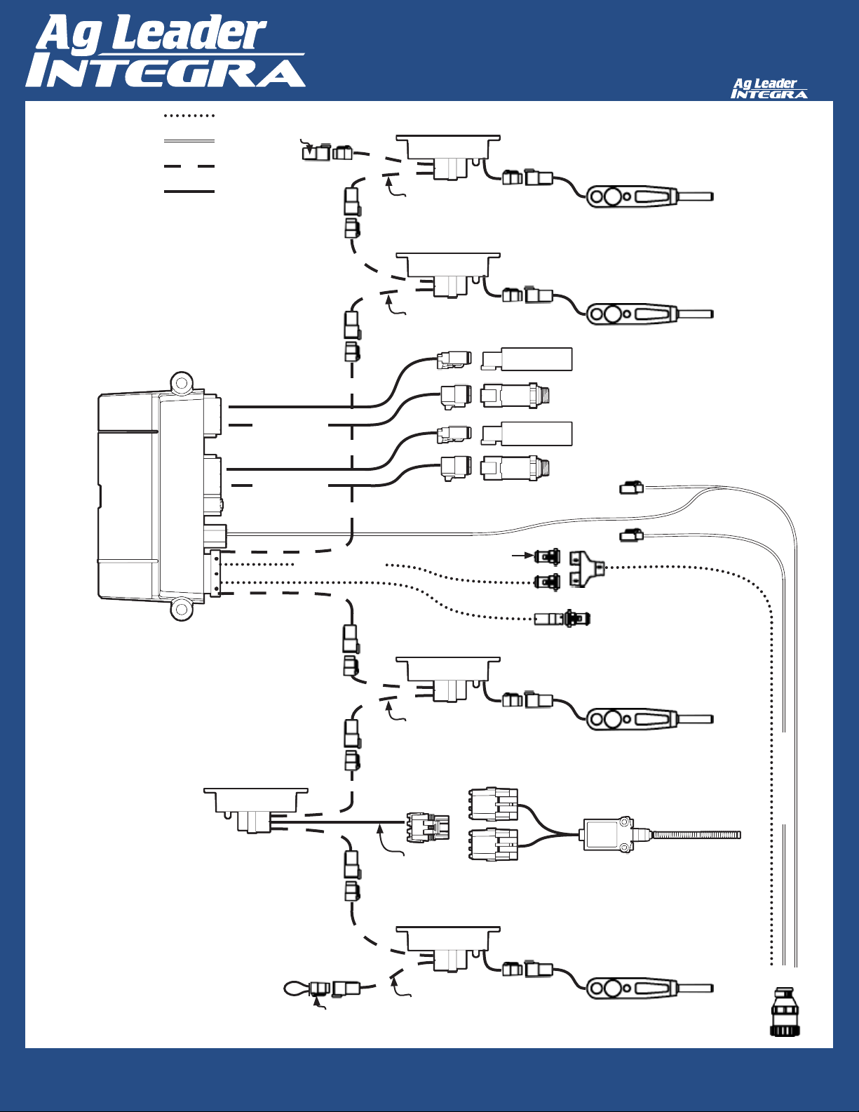
CAN A
HIGH POWER
LOCAL CAN BUS
SIGNAL/CONTROL
At least one implement switch must be installed on the
Seed Command system.
Terminator
P/N 4002871
Right End of Planter
Terminating
Plug P/N
4002871 must
be installed on
the right end of
the planter.
Channel Cable
Channel Cable
Row Module
P/N 4002912-1
Row Module Breakout
Row Module
P/N 4002912-1
Row Module Breakout
Cable Diagram
Load Sensor
Load Sensor
Channel 2 Solenoid Valve
Channel 2 Pressure
Channel 1 Solenoid Valve
Channel 1 Pressure
Down Force Control Module
Control module and Implement Switch module(s) can
be placed anywhere in series on the local CAN Bus.
CAN Implement Switch
P/N 4002911
P/N 4002920-008
Dust Cap
Row Module
P/N 4002912-1
Row Module Breakout
P/N 4002658
Row Module
P/N 4002912-1
Load Sensor
P/N 4000726-12
Implement Switch
Terminator
P/N 4002870
Left End of Planter
Row Module Breakout
Terminating Plug P/N 4002870 must be
installed on the left end of the planter.
Quick Reference Guide
AL: 2006350 ENG Rev B
Load Sensor
4
Page 5

Hydraulic Downforce
Installation: Hydraulic Down Force FAQ
Where do I plug in an implement switch?
Generation 1 modules will broadcast the implement switch status over the CAN bus. No additional
implement switch is needed.
What if I don’t have any other generation 1 modules?
You will use the Ag Leader CAN implement switch module P/N 4002911 and cable P/N 4002658 in
conjunction with the standard implement switch.
What if my cables don’t reach the rows for which I have installed gauge wheel
sensors?
It may be acceptable to choose rows the cables will reach, as long as channel 2 sensors are on the
center 6 rows, and channel 1 sensors are outside that.
What if I don’t have any free SCV connections for the down force valve?
Teeing into existing lines is acceptable. Do not tee into the vacuum fan line if adjusting fan RPM
on the tractor with a knob or dial. Teeing into the line before a ow limiter on the planter would be
acceptable. Teeing into the hydraulic drive supply line would be the best option. Do not tee into
Rawson Drive supply line.
What if my hydraulic oil gets too hot?
Ag Leader sells a Load Sense kit (P/N 4101225) to help manage oil temperatures. Note: This
system will not help if using SCV to control hydraulic drives. In this case, an auxiliary oil cooler
may need to be installed.
What if my hydraulic actuator does not extend far enough to reach the lower bracket
with row unit at bottom travel?
Purchase one spacer kit (P/N 4101201) per row. This will install at the bottom of the ram.
(Commonly used on John Deere long parallel arms)
My Kinze planter has rows that are offset 4” back, causing the upper actuator bracket
to not line up with the lower actuator bracket.
Purchase one spacer kit (P/N 4101204) per row. This will move the upper bracket 4” rearward.
How does the system know the difference between the row modules on channel 1 and
those on channel 2?
The Channel 1 row modules will connect to the cable labeled “Type 1” while channel 2 row modules
will connect to “Type 2” cables.
Quick Reference Guide
AL: 2006350 ENG Rev B
5
Page 6

Hydraulic Downforce
Installation: Hydraulic Down Force FAQ
Am I missing something to plug into the 3 pin connector on the master hydraulic down
force module?
This connector is not used.
Why is the gauge wheel load bar graph constantly spiking and then going to 0?
This can happen if the Channel 1 pressure lines are routed to channel 2 sensors. Ensure channel
1 components (Down force pressure, and gauge wheel load sensor wiring) are on the wings,
and channel 2 components are on the center 6 rows. Ensure channel hoses are going to correct
channel of down force valve. Ensure PWM/pressure sensor cables are going to correct channel of
Down Force Module and Down Force Valve.
What are the red knobs on the down force valve?
This allows for manual adjustment of down force in the event of electronics failure. Push and twist
the knob to move between automatic adjustment (inner position) and manual adjustment (outer
position).
Why does the system need 3 hydraulic lines (Pressure, Return and Tank)
Under normal operation, pressure in the down force system is increased through the Pressure line
and relieved through the Return line. When the planter runs over a terrace or a water way, the
access pressure is released through the Tank line. All three lines MUST be connected.
Quick Reference Guide
AL: 2006350 ENG Rev B
6
Page 7

Hydraulic Downforce
Hydraulic Down Force
Alarm Explanation and Resolution
Down Force Inadequate
Problem: System is at maximum hydraulic pressure, but does not achieve an acceptable gauge
wheel load. Often times this alarm occurs when down force actuators are lifting the planter tool
bar.
Resolution: Add weight to planter. If planter tool bar is not lifting, increase maximum down force set-
ting in conguration setup.
Hydraulic Pressure too low
Problem: Hydraulic pressure is at 0 and the system is demanding more pressure.
Resolution: Check hydraulic hoses for proper connections. Ensure SCV remote is set for continuous
ow. Zero each channel’s pressure sensor only when mechanical gauge reads 0 psi.
Low Gauge Wheel Load
Problem: Down force system is not achieving an acceptable gauge wheel load.
Resolution: Increase aggressiveness for problematic channel under settings button from run screen.
This alarm may be followed by Down Force Inadequate, in which case consult that alarm resolution section.
Pressure Sensor Failure
Problem: Pressure sensor is outside voltage range.
Resolution: swap cables with other channel (if applicable), re-zero pressure sensors. If problem
persists on same channel, replace pressure sensor. If problem is now on other channel, inspect/
replace cable.
Row Module Communication Lost
Problem: Row module communication lost.
Resolution: Inspect cabling of row module. Replace row module.
Row Module Failure
Problem: Row module is not sensing inputs. Row module is power cycling at intervals of less than 2
seconds
Resolution: Swap module with different row. If problem follows, replace module. If problem exists on
same row, inspect or replace load sensor.
# Row Modules does match the display conguration
Problem: Conguration was set to a number of sensors that was not detected by the system.
Resolution: Create a conguration that matches the number of sensors used. Check that all row
modules are communicating. Flashing green LED on the row module indicates proper communication.
Quick Reference Guide
AL: 2006350 ENG Rev B
7
Page 8

Hydraulic Downforce
Troubleshooting Step 1A: Hydraulic Down Force
Start
Latest
Display
rmware?
Yes
Down
Force icon
present on lower right
run screen.
Yes
Enter 5 mph manual ground
speed.
Is
arrow icon
green when planter is
lowered?
Yes
Is
arrow icon
yellow when planter is
raised?
No
No
No
Implement Switch
No
Implement Switch
Upgrade
rmware
Go to Step 3:
Connections
Go to Step 3:
Connections
Down
Force Module
Communicating?
Yes
Operating
Conguration set to
control?
Yes
Restart eld operation, select
Down Force on Product
Selection screen accept
Down Force Warning
No
Cables and Power
No
Go to Step 2:
Set Operating conguration
to Control instead of
Monitor Only
Yes
Go to Step 1B:
Hydraulic Down
Force
Quick Reference Guide
AL: 2006350 ENG Rev B
8
Page 9

Hydraulic Downforce
Troubleshooting Step 1B: Hydraulic Down Force
Continued from Step 1A:
Hydraulic Down Force
Engage down force
hydraulics.
In
Manual
Control click the
increase arrow several
times. Does pressure
increase?
Yes
Put planter in down position
with load on gauge wheels.
Place in manual control at
maximum pressure.
No
Go to Step 4:
Hydraulics
Enter
down
force module
diagnostics. Do all row
sensors register a load
reading?
Yes
Decrease
pressure
in manual control.
Does the pressure
displayed go
down.
Yes
Return system to desired
control mode. Manual/
Automatic
Troubleshooting Complete.
System should be in eld-ready
state.
With planter still in down
position with load on gauge
No
wheels and in manual control
at maximum pressure
Move to softer ground or
pull forward. The opening
discs are not digging into the
No
Go to Step 4:
Hydraulics
ground.
Can
the gauge
wheels on the monitored
rows be turned by hand?
Yes
No
Cables and Power
Go to Step 2:
Quick Reference Guide
AL: 2006350 ENG Rev B
9
Page 10

Hydraulic Downforce
Troubleshooting Step 2: Power and Cables
Start
Lights
present on Down
Force Module?
Yes
Are all lights
green?
Yes
Are row module
lights green?
Yes
Does
cabling match
the Figure 1: Cable
Diagram?
Yes
No
No
No
No
Go to Step 5:
Indicator Lights
Go to Step 5:
Indicator Lights
Correct cabling errors to
match Figure 1: Cable
Diagram.
Display powered
on?
Yes
Is
CAN A
connected?
Yes
Check power control relay.
No
No
Power on Display
Connect CAN A
Troubleshooting Complete.
System should be in eld-ready
state.
Quick Reference Guide
AL: 2006350 ENG Rev B
10
Page 11

Hydraulic Downforce
Troubleshooting Step 3:
Implement Switch Connections
NOTE: A minimum of 1 implement switch (2 is recommended) must be installed
on planter for the down force system to work properly. If an implement switch is
already installed and connected to an existing SeedCommand module, no action is
required. If no implement switch is installed, action must be taken to install at least 1
implement switch and implement switch module on local down force CAN Bus.
When using the hydraulic down force module with existing Seed Command modules,
the implement switch must be connected to the module highest in the hierarchy
below:
Hydraulic Seed Rate Control Module
Clutch Control Module
Seed Tube Monitor Module
Implement switches connected to any non Seed Command related module will not
indicate planter up/down status for Hydraulic Down Force control. (App Rate Module
and Liquid Control Module included)
If none of the above 3 seed command modules are used then the Hydraulic Down
Force module must have a CAN implement switch installed.
Part numbers required for CAN implement switch installation:
Part Number Description
4002911 Module – CAN implement switch
4002658 Cable – CAN implement switch
4001507 Implement Switch
Implement Switch Kits (contain Implement Switch 4001507)
4100830 Kinze
4100831 John Deere
4100832 White
4100833 Case
Quick Reference Guide
AL: 2006350 ENG Rev B
11
Page 12

Hydraulic Downforce
Troubleshooting Step 4: Hydraulics
Start
Is Tractor
running with hydraulics
engaged?
Yes
At the down force control
valve, move the red circular
manual override knobs to
the other position (electronic
control override).
Is a pressure
displayed on the
valve’s gauge?
Yes
Move red circular override
knobs to the inner position
(automatic control).
From
the
display, Can
pressure be released
from the system using the
down arrow in manual
control?
Yes
From
the
display, Can
pressure be increased
in the system using the up
arrow in manual
control?
Start Tractor and engage
No
No
No
Ensure Pressure, Return and
No
system is set for continuous
hydraulics
Adjust manual override
pressure using allen head
adjustment just above the
electronic PWM valve.
pressure still
at 0?
Tank lines are completely
connected. Ensure SCV
remote is engaged in the
correct direction. Ensure
ow (motor mode).
No
Is
Yes
Yes
Troubleshooting Complete.
System should be in eld-ready
state.
Quick Reference Guide
AL: 2006350 ENG Rev B
12
Page 13

Hydraulic Downforce
Troubleshooting Step 5:
Indicator Lights
Light 2
(Proprietary CAN)
Light 1
(ISO CAN)
Power
Off Solid
Red
Boot No Power N/A No App Running N/A N/A N/A
Upgrade No Power N/A N/A N/A Running N/A N/A
Main
Application
No Power
High Current
Power Low
Flashing
Red
N/A N/A N/A Power OK N/A
Solid
Amber
Flashing
Amber
Solid
Green
Light 1 (ISO CAN)
Boot N/A N/A N/A N/A N/A N/A N/A
Upgrade Idle Bus Off N/A Bus Error
Passive
Main
Application
Idle Bus Off N/A Bus Error
Passive
Bus Error
Active
Bus Error
Active
N/A TX/RX
N/A TX/RX
Light 2 (Proprietary CAN)
Boot N/A N/A N/A N/A N/A N/A N/A
Upgrade N/A N/A N/A N/A N/A N/A N/A
Main
Application
Idle Bus Off N/A Bus Error
Passive
Bus Error
Active
N/A TX/RX
Power
Flashing
Green
Down Force
Row Unit Module
Local CAN
Off Solid
Red
Boot N/A N/A Upgrade
Main
Application
Idle Bus Off N/A Bus Error
Quick Reference Guide
AL: 2006350 ENG Rev B
Flashing
Red
State
Solid
Amber
N/A N/A N/A N/A
Passive
Flashing
Amber
Bus Error
Active
Solid
Green
N/A CAN OK
Flashing
Green
13
 Loading...