

Page 1

Operators Manual
Firmware Version 5.4
Ag Leader PN 4002722 Rev. G
Page 2

Firmware Version 5.4
Page 3

Table of Contents
General
T
ABLE
OF
C
About this Manual
Introduction and Company Profile............................................................................1
Display......................................................................................................................1
Service......................................................................................................................1
System Uses ............................................................................................................2
System Features ......................................................................................................2
USB Flash Drive.......................................................................................................3
Color Touch Screen..................................................................................................3
CAN BUS Technology..............................................................................................3
Technical Specifications...........................................................................................3
System and Upgrades..............................................................................................3
Automated Module Firmware Upgrade.....................................................................4
Product Registration.................................................................................................4
Conventions Used In This Manual............................................................................4
Cautions and Warnings............................................................................................4
Cross-references and Web Links.............................................................................4
Viewing this Manual Online......................................................................................5
How to Find Information You’re Looking For............................................................5
Installation
Display Hardware.....................................................................................................7
Installation Instructions.............................................................................................7
Fuse Installation and Replacement..........................................................................9
Screen Icon Conventions .........................................................................................9
ONTENTS
Setup
Configuration
Initial Startup...........................................................................................................11
Advanced Options.............................................................................................11
Location Specific Setup.....................................................................................12
Single Display ...................................................................................................12
Multiple Display Setup - First Display................................................................13
Multiple Display Setup - Additional Display.......................................................14
Import Setup Data ..................................................................................................14
Import Files .......................................................................................................14
Home Screen..........................................................................................................15
Setup buttons .........................................................................................................16
Display button.........................................................................................................16
General tab .......................................................................................................17
iii
Page 4

Display tab........................................................................................................18
Features tab ..................................................................................................... 18
Unlocking Features..................................................................................... 19
Advanced tab....................................................................................................19
Configuration button...............................................................................................21
Configuration tab.............................................................................................. 21
Product tab....................................................................................................... 22
Planting Settings......................................................................................... 23
Application Settings.....................................................................................23
Grain Harvest Settings................................................................................ 23
Management Setup
Configuration Selection .................................................................................... 25
All Modules Detected............................................................................. 25
Modules Missing....................................................................................25
Some Modules Not Detected................................................................. 26
Modules not the same as previously used............................................. 26
Events...............................................................................................................27
Setting mode (Traditional or Events Only) using Permissions.................... 27
Starting an Event.........................................................................................28
Managing Events ........................................................................................ 28
Management button..........................................................................................30
Grower/Farm/Field tab......................................................................................30
Grower ........................................................................................................ 30
Farm and Field. ........................................................................................... 31
Importing and Exporting Field Boundaries.................................................. 32
Season tab ....................................................................................................... 33
Users tab.......................................................................................................... 33
Add a User.................................................................................................. 34
User Setup button....................................................................................... 34
General tab............................................................................................ 35
Phone/Email tab .................................................................................... 35
Address tab............................................................................................35
Permissions......................................................................................................35
Operators.................................................................................................... 35
Managers................................................................................................... 35
Permission Level For Operators....................................................................... 36
Full Permission............................................................................................36
Basic Permission.........................................................................................36
Custom Permission.................................................................................... 37
Accessing Setup Menus...................................................................................39
Accessing USB.................................................................................................39
Forgotten Passwords........................................................................................39
Businesses tab................................................................................................ 40
Field Operations
Operator Selection............................................................................................43
Operator Log Out..............................................................................................44
Configuration Setup Screen...................................................................................44
iv Firmware Version 5.4
Page 5

Setup Event............................................................................................................45
Field Finder.......................................................................................................46
Field Operation Options....................................................................................46
Run screens ...........................................................................................................47
GPS Signal Indicator.........................................................................................49
Mapping Toolbox...............................................................................................50
Map Legend tab...........................................................................................51
Map Options ................................................................................................51
Legend Settings .....................................................................................52
Markers tab..................................................................................................53
Edit Markers...........................................................................................53
Field Tab......................................................................................................54
Boundary................................................................................................54
Boundary Settings..................................................................................55
Create Boundary....................................................................................55
Pause Boundary.....................................................................................55
Headlands.........................................................................................................56
Active Area ..................................................................................................56
Add a Headland...........................................................................................56
Headland Types.....................................................................................57
Load Headlands...........................................................................................58
Edit Headlands ............................................................................................58
Headland Alarm Settings.............................................................................59
Topography............................................................................................59
Setup Map Screen..................................................................................60
Video.................................................................................................................62
T
ABLE
OF
C
ONTENTS
External Drive
External Storage Operations..................................................................................65
Upgrade Firmware ............................................................................................65
Import Files .......................................................................................................65
.AGSETUP...................................................................................................65
.AGDATA.....................................................................................................66
Export Files.......................................................................................................66
.AGSETUP...................................................................................................66
.AGDATA.....................................................................................................66
Export Reports.............................................................................................67
Manage Files.....................................................................................................67
Advanced Options.............................................................................................67
Devices
Device Information..................................................................................................69
Devices .............................................................................................................69
Display Diagnostics...........................................................................................69
Settings
Equipment Settings ................................................................................................71
Implement Switch Settings (for Area Logging) ............................................71
Equipment Configuration Settings for Rate Control.....................................72
v
Page 6

Speed Input Settings..............................................................................................72
Calibrate Distance............................................................................................ 73
Auxiliary Input ........................................................................................................ 74
Auxiliary Input Settings..................................................................................... 75
Auxiliary Input: Help..........................................................................................75
Auxiliary Input Diagnostics ...............................................................................75
AutoSwath..............................................................................................................76
Look-Ahead Settings...................................................................................77
Vehicle Offsets. ...................................................................................................... 77
Antenna Offsets tab..........................................................................................78
Hitch Tab Settings tab...................................................................................... 78
Mount Tab Settings (for some Application vehicles) ........................................ 78
Head Tab (for Harvest vehicles)....................................................................... 78
Swath Section Offsets......................................................................................78
Section Offsets............................................................................................79
Virtual Terminal
Common Terminology............................................................................................81
Auxiliary Assignment..............................................................................................83
VT Alarms and Trouble Codes............................................................................... 84
Task Controller.......................................................................................................85
Configuration Setup............................................................................................... 85
ISOBUS Settings ................................................................................................... 86
AgFiniti
Connecting to Wi-Fi Network.................................................................................87
Connecting to AgFiniti............................................................................................88
File Transfer........................................................................................................... 89
Importing and Exporting Files........................................................................... 89
Viewing Files .................................................................................................... 89
Export Settings.................................................................................................90
Importing a Prescription....................................................................................91
Importing a Variety Reference Map (Harvest Only).......................................... 92
Remote Support.....................................................................................................92
Remote Support Permissions Options ............................................................. 92
GPS
GPS
GPS Button............................................................................................................ 95
Setup......................................................................................................................95
GPS Settings....................................................................................................95
OmniSTAR Settings............................................................................................... 97
OmniSTAR Settings — GPS 2500.........................................................................98
Serial Port Settings................................................................................................ 99
GPS Information .................................................................................................. 101
GPS Information - General Tab......................................................................101
vi Firmware Version 5.4
Page 7

Satellite Plot...............................................................................................103
GPS Information - Receiver Tab.....................................................................103
GPS Information - OmniSTAR Tab.................................................................104
RTK/NTRIP Information.............................................................................104
GPS Information - NTRIP................................................................................105
GPS Information for 2500 RTK.......................................................................105
2500 RTK Setup..............................................................................................106
Guidance
Guidance
Guidance/Steering Control...................................................................................107
Setup....................................................................................................................107
Lightbar Settings...................................................................................................108
Setup....................................................................................................................108
Guidance Tab on Mapping Toolbox .....................................................................108
New Pattern..........................................................................................................109
Straight............................................................................................................109
Select Pattern............................................................................................109
Create AB line using 2 points ....................................................................109
Create AB line using Current Location and Heading.................................109
Create AB line using Current Location and Inputting Heading..................109
Adaptive Curve................................................................................................110
Select Pattern............................................................................................110
Create AB line using 2 points ....................................................................110
Identical Curve................................................................................................111
Select Pattern............................................................................................111
Create AB line using 2 points ....................................................................112
Pivot................................................................................................................112
Select Pattern............................................................................................113
Create AB line using driven path...............................................................113
SmartPath.......................................................................................................114
Select SmartPath.......................................................................................114
Inputting Paths into SmartPath..................................................................115
Cycle between Loaded Paths....................................................................115
Select a Previous SmartPath Pass............................................................116
SmartPath Guidance Options....................................................................116
AutoSave..............................................................................................................117
Manage Patterns..................................................................................................118
Spatial Sort...........................................................................................................118
Import Pattern .................................................................................................118
Export Pattern.................................................................................................118
Edit Pattern .....................................................................................................118
Remove Pattern/Remove All Patterns ............................................................119
Reset Pattern..................................................................................................119
Pattern Groups.....................................................................................................119
Guidance Options.................................................................................................120
T
ABLE
OF
C
ONTENTS
vii
Page 8

Save ............................................................................................................... 120
Pause ............................................................................................................. 121
Remark A........................................................................................................ 121
Nudge............................................................................................................. 121
Shift ................................................................................................................ 122
Steering.......................................................................................................... 123
OnTrac Tuning................................................................................................123
Lightbar...........................................................................................................124
Tramlines........................................................................................................124
OnTrac2+
AutoSteer Setup Screen...................................................................................... 127
Vehicle................................................................................................................. 128
Setup Wizard..................................................................................................128
Manage Vehicle..............................................................................................129
Select..............................................................................................................129
Edit ................................................................................................................. 130
Delete............................................................................................................. 130
Export/Import.................................................................................................. 130
Export profile to a USB drive ............................................................... 131
Import profile to a USB drive................................................................ 131
Auto Calibrate...................................................................................................... 131
Adjust Lateral Offset..................................................................................132
Steering Adjust............................................................................................... 133
Steering Components..................................................................................... 134
OnTrac2 ECU............................................................................................134
Manual Steering Override......................................................................... 134
Remote Engage Switch............................................................................. 134
MDU. ......................................................................................................... 134
System Menu....................................................................................................... 135
System Health................................................................................................ 135
Manage Settings.............................................................................................136
Log Files....................................................................................................136
Database...................................................................................................137
Reset Factory Default ...............................................................................137
Accessories....................................................................................................137
Technician...................................................................................................... 138
Software Upgrade...........................................................................................138
GPS Diagnostics..................................................................................................138
Details.................................................................................................................. 139
Tillage
Create Tillage Configuration................................................................................ 141
Configuration Setup............................................................................................. 141
Load Configuration......................................................................................... 142
Run Configuration................................................................................................ 142
viii Firmware Version 5.4
Page 9

Planting
T
ABLE
Create Planting Configuration
Create Equipment Configuration..........................................................................145
AutoSwath
Row Shutoff..........................................................................................................149
Configuration Setup ........................................................................................149
Row Shutoff Look-Ahead Numbers.................................................................149
Automatic AutoSwath Control...............................................................................150
Look-Ahead Settings .................................................................................150
Checking AutoSwath Performance for Row Shutoff .......................................151
Fixing Overplanting and Underplanting in AutoSwath.....................................152
Rate Control
Hydraulic Seed Rate Control................................................................................153
Controller Settings for Hydraulic Seed Rate Motor Drives..............................153
Channel Tab settings.................................................................................154
Control Valve Settings - PWM..............................................................154
Control Valve Settings - Servo.............................................................155
Auxiliary Tab settings.................................................................................155
Hydraulic Seed Controller Settings for Specific Planters................................156
Hydraulic Seed Meter Calibration Numbers....................................................157
Stepper Seed Rate Control ..................................................................................158
Controller Settings for Stepper Seed Rate Motor Drives ................................158
Channel Tabs ............................................................................................159
Auxiliary Tab..............................................................................................159
Gear Ratio Calculations for Seed Rate Motors...............................................160
Gear Ratio Drawing - For Single Motor Drive............................................160
Gear Ratio Drawing - For Multiple Drive Combinations.............................161
Seed Ratio Calculation Example Procedure..............................................161
Gear Ratio Drawing Shaft Drives...............................................................162
Planter Options Screen ........................................................................................163
Priming Seed Rate Meters ...................................................................................163
Calibrating Seed Rate Meters ..............................................................................163
Rate Control: Map Screen....................................................................................164
Product Control Toolbox.......................................................................................165
Rate Control Settings......................................................................................166
Loading Prescriptions...........................................................................................166
Showing Prescriptions on the Map Screen.....................................................167
Troubleshooting....................................................................................................167
Hydraulic Seed Control: Zero Flow Offset Variation .......................................167
Hydraulic Seed Control: Zero Flow Offset Variation .......................................168
Stepper Seed Control Meter Alarms...............................................................168
Planting Map Screen - Zoom to Extent...........................................................169
Planting Map Screen - Zoom Detail................................................................169
Legend Select.................................................................................................169
OF
C
ONTENTS
ix
Page 10

Legend Setup............................................................................................170
Application
Liquid Rate Control
Create Configuration ...................................................................................... 171
Implement Offsets .......................................................................................... 173
Controller Settings.......................................................................................... 174
Creating Products...........................................................................................174
CREATING SINGLE PRODUCTS............................................................ 175
CREATING PRODUCT TEMPLATE......................................................... 175
Load Configuration......................................................................................... 177
Mix Calculator.................................................................................................179
Configuration Setup........................................................................................180
Hardi Safe Track.............................................................................................181
Liquid Application Controller Settings............................................................. 182
Control Valve Settings - PWM................................................................... 183
Control Valve Settings - Servo, Calibrated Reflow and Ramsey Valve .... 184
Calibrate Pressure .................................................................................... 184
Fence Row Nozzle Indicators.........................................................................185
Load Configuration......................................................................................... 185
Run Configuration...........................................................................................185
Application Map screen - Zoom to Detail........................................................ 186
Legend Select.................................................................................................186
Rate Control: Product Control Toolbox................................................................187
Rate Control Settings ..................................................................................... 188
Rate Control: Container Level........................................................................ 189
Tank Fill.....................................................................................................189
Tank Empty...............................................................................................189
Tank Partial Fill ......................................................................................... 189
Adjust Container Amount..................................................................... 189
Tank Alarms.............................................................................................. 190
Loading Prescriptions .......................................................................................... 190
Showing Prescriptions on the Map Screen..................................................... 191
Shape File Conversion.........................................................................................191
Liquid Application Diagnostics........................................................................ 193
Troubleshooting DirectCommand Liquid Applications.................................... 193
John Deere Specific Instructions .........................................................................196
Master Switch Input........................................................................................ 196
Master Switch Usage......................................................................................196
Target Rate.....................................................................................................196
Data Collection............................................................................................... 196
AutoSwath Boom Section Control.................................................................. 196
SprayStar Application Rate ............................................................................ 196
SprayStar Rinse Cycle ...................................................................................196
Control Valve Settings ......................................................................................... 197
Liquid Product Control Valve Configuration Options................................. 197
x Firmware Version 5.4
Page 11

Servo Control Valve Settings (By Manufacturer) ............................................198
Liquid Servo Settings Description...................................................................202
Liquid PWM Control Valve Settings Description.............................................202
Dickey-John NH3 Conversions.......................................................................203
Conversion Formulas.................................................................................203
Troubleshooting Serial Control Applications...................................................203
Miscellaneous.......................................................................................................204
Glossary of Application Settings .....................................................................204
Configuration Settings ...............................................................................204
Speed Input Settings .................................................................................204
Automatic Swath Control Settings.............................................................204
Auxiliary Input Settings..............................................................................205
Controller Settings.....................................................................................205
Fertilizer default Product Settings...................................................................207
Application
ISOBUS Serial Application Rate Control
Enable Virtual Terminal and Task Controller........................................................209
Setup....................................................................................................................210
Status Screen.......................................................................................................212
Settings Screen....................................................................................................213
Manage Configurations...................................................................................213
Alarm Settings......................................................................................................213
Diagnostics...........................................................................................................214
T
ABLE
OF
C
ONTENTS
Injection
Create Configuration.......................................................................................215
Setup Configuration ........................................................................................215
Rate Response Warning......................................................................215
Flow Monitor Warning ..........................................................................216
Calibrating an Injection Pump....................................................................216
Priming an Injection Pump.........................................................................217
Load Configuration..........................................................................................218
Run Configuration...........................................................................................218
Injection Diagnostics.......................................................................................219
Troubleshooting Direct Injection Configurations .............................................219
Direct Injection: Pump Doesn’t Run...........................................................220
BATTERY POWER PIN OUTS ............................................................................221
Direct Injection: Pump Runs Full Speed....................................................221
Digital Pump Speed Pin Outs...............................................................................221
Analog Speed Pin Outs........................................................................................222
Direct Injection: Application Error ..............................................................222
Direct Injection: Discharge Flow Sensor Error...........................................222
Discharge Flow Sensor Pin Outs..........................................................................223
Direct Injection: Inlet Restriction................................................................223
Vacuum Switch Pin Outs......................................................................................223
xi
Page 12

Controller Settings: Direct Injection Pump Calibration.............................. 223
Pump Calibration Setting..................................................................... 223
Rate Response Warning...................................................................... 224
Flow Monitor Warning.......................................................................... 224
Field Notes................................................................................................224
Setting Name and Description............................................................. 224
Run Screen............................................................................................... 224
NORAC UC5
Norac Unlock..................................................................................................225
Create Configuration ...................................................................................... 225
Setup Configuration........................................................................................226
Load Configuration......................................................................................... 227
Run Configuration...........................................................................................228
Engage button...........................................................................................228
Boom Height Control Options Button........................................................ 228
Boom Height Control Options Screen....................................................... 229
Boom Height Diagnostics...............................................................................229
Spreader
Create Configuration ...................................................................................... 231
Controller Settings.......................................................................................... 233
Spreader Control: PWM Control Valve ..................................................... 234
Spreader Control: Servo Control Valve..................................................... 234
Spreader Control: Spinner Tab.................................................................235
Creating Products...........................................................................................236
CREATING SINGLE PRODUCTS............................................................ 236
CREATING DRY FERTLIZER BLENDS................................................... 236
Load Configuration......................................................................................... 238
Run Configuration...........................................................................................239
Automatic Spinner Control...................................................................................239
Spinner Spreader, with two-bin configuration...................................................... 240
Run Time Operations .....................................................................................240
Spreader Control screen...........................................................................240
Conveyor Rate Look-Up...................................................................... 241
Fan Frame & Feed Gate Actuator Settings ......................................... 242
Spreader Control: Routine Operations ................................................ 242
Spreader Control: Chain Oiler ............................................................. 242
Spreader Control: Static Calibration.................................................... 243
Spreader Control: In-Field Calibration................................................. 244
Troubleshooting DirectCommand Granular Applications ............................... 244
Troubleshooting Serial Control Applications................................................... 245
Strip Till
Create Strip Till Fertilizer Configuration.......................................................... 247
Create Air Seeder Configuration ....................................................................249
Controller Settings.......................................................................................... 251
Strip Till Control: Servo Control Valve....................................................... 252
Strip Till Control: PWM Control Valve....................................................... 253
xii Firmware Version 5.4
Page 13

Linear Actuator/Clutch Settings.................................................................253
Actuator/Clutch Logic................................................................................255
Fertilizer Blend Setup ................................................................................255
Load Configuration..........................................................................................256
Run Configuration...........................................................................................256
Meter Prime...............................................................................................256
Run Time Operations......................................................................................258
Strip-Till (Three-Bin Configuration).......................................................................258
Strip Till Control Screen.............................................................................259
Static CFR Calibration Procedure for Hydraulic Drive systems ...........259
Static CFR Calibration Procedure for Ground Drive Systems..............260
In-Field Calibration Procedure (Strip Till).............................................261
Strip Till Control: Auxiliary Tab ..................................................................262
Troubleshooting DirectCommand Granular Applications................................262
Troubleshooting Serial Control Applications...................................................263
Fertilizer Default Product Settings...................................................................264
Harvest
T
ABLE
OF
C
ONTENTS
Harvest Monitoring/Mapping
Display Preparation.........................................................................................265
Vehicle Inspection...........................................................................................265
Create Configuration.......................................................................................265
Configuration Setup ........................................................................................265
Calibration Sequence ................................................................................265
Calibrate Distance...........................................................................................266
Calibrate Header Sensor...........................................................................266
Input Header Offset ...................................................................................267
Vibration Calibration........................................................................................267
Temperature Calibration .................................................................................268
Moisture Calibration........................................................................................268
Manual Moisture Setting............................................................................269
Grain Weight Calibration.................................................................................269
Turn On/Off Auto Calibration...........................................................................270
AutoSwath Sensitivity Settings........................................................................270
Load Configuration..........................................................................................271
Run Configuration...........................................................................................271
Harvest Status Items.......................................................................................272
Harvest Diagnostic Button on Map Screen.....................................................273
Map Options....................................................................................................273
Map Screen: Flow Delay.................................................................................274
Grain Harvest Diagnostics....................................................................................274
Claas Quantimeter
Create Configuration.......................................................................................277
Configuration Setup ........................................................................................277
Calibration Information....................................................................................278
xiii
Page 14

Load Configuration......................................................................................... 278
Manual Moisture Setting ........................................................................... 279
Map Screen for CLAAS Quantimeter ............................................................. 280
Diagnostics for CLAAS Quantimeter.............................................................. 280
Diagnostics Screen for CLAAS Quantimeter ............................................ 280
Bridge Module......................................................................................281
Troubleshooting CLAAS Quantimeter Configurations.................................... 281
Appendix
Appendix
System Diagrams Reference............................................................................... 283
Current File Formats............................................................................................ 283
.AGSETUP ..................................................................................................... 283
.AGDATA........................................................................................................283
Legacy File Formats ............................................................................................284
Prescription Map File Types...........................................................................284
Boundary and Guideline File Types ............................................................... 284
Image File Types............................................................................................284
System File Types.......................................................................................... 284
Module LED Diagnostic States............................................................................ 285
Company Warranty Statement............................................................................. 285
Unauthorized Access........................................................................................... 285
PROPRIETARY TECHNOLOGY NOTICE.......................................................... 286
COPYRIGHT NOTICE.........................................................................................286
SERVICE AND SUPPORT.................................................................................. 286
xiv Firmware Version 5.4
Page 15

GENERAL
GENERAL
ABOUT THIS MANUAL
INTRODUCTION AND COMPANY PROFILE
G
ENERAL
A
BOUT
THIS
ABOUT US
Welcome to the Ag Leader Technology family. Ag Leader Technology, Inc. is the global leader in yield
monitor and precision farming systems and is committed to meeting the present and future needs of the
agriculture industry by providing high quality products and first class customer support.
INNOVATION
Ag Leader Technology manufactures and sells products which support a wide array of precision farming
practices. These include grain yield monitoring, application rate control and monitoring, variable rate
fertilizer application, site-verification, GPS guidance and interface to Autosteer technologies.
COMPATIBILITY
Ag Leader Technology offers compatibility and supports integration of many different types and brands
of equipment used for precision farming. The latest equipment available is supported as well as older
series of combines, planters, sprayers, tillage equipment, etc.
QUALITY AND SUPPORT
Ag Leader Technology continues to provide the best customer support in the industry. Precision farming
doesn't come without questions. Ag Leader is committed to providing the most responsive,
knowledgeable and friendly technical support available. Our technical support team is available sevendays-a-week during peak seasons to answer your questions on the operation of Ag Leader products.
WE WANT TO HEAR FROM YOU!
M
ANUAL
Feel free to call and discuss:
• Operational questions about the display
• Features you would like to see implemented to improve the system or features you would like to see added
to the system to increase functionality
DISPLAY
The display is a full-featured, year-round hub of any precision farming operation. A full-color, highbrightness, high-resolution touchscreen display is easy to read and offers powerful, year-round precision
farming tools. Built-in manual guidance, full-screen mapping, planter and application control, yield
monitoring, real-time data logging and automated steering make up the core functionality of the display.
WARNING: Read manual completely before operating display. Understand and follow all operating and
safety instructions for proper use of this display . Failur e to use display properly could result in an impairment
of the safety features of this product.
SERVICE
There are no user-serviceable parts inside the display. Contact the manufacturer for a Return Material
Authorization (RMA).
1
Page 16

ph: (515) 232-5363
fax: (515) 232-3595
e-mail: support@agleader.com
CAUTION: This display has an internal lithium coin cell battery that is good for the life of the product and
does not need to be replaced. There is a risk of explosion if the battery is replaced by an incorrect type.
Dispose of used batteries according to the battery manufacturer’s instructions.
SYSTEM USES
• Manual Guidance
• ParaDyme™ and GeoSteer™ automated steering
• OnTrac2+™ Assisted Steering
• Norac UC5
• Video Camera Inputs
• Mapping tillage operations
• Mapping and logging product application
• Mapping of all field boundaries, sub-boundaries, waterways and terraces
• Grain yield monitoring
• Variety logging
• Granular and liquid fertilizer application
• Liquid spray system control
• NH3 application control
• Application control of multiple bin spinner spreaders
SYSTEM FEATURES
• Rugged sealed enclosure
• Compatible with most NMEA GPS receivers
• DirectCommand and SeedCommand product con trol using industry- standard CAN-bus interface
• Adjustable volume control
• Perspective 3D View Map
• Automatic field selection
• Automated module firmware upgrade
• Advanced GPS Diagnostics
• USB media slot
• 28-pin plug compatible with other Ag Leader displays.
• 28-pin auxiliary connection
• RAM mount
2 Firmware Version 5.4
Page 17

G
ENERAL
USB FLASH DRIVE
Display kits include a USB Flash Drive which you can use to save and transfer your data in and out of
the display.
COLOR TOUCH SCREEN
A
BOUT
THIS
The display features a color touch screen display. The touch screen allows easy and intuitive navigation
through the screens on the display without the need for any external keypad or mouse devices. Here are
a few key things to remember if you are new to using a touch screen device:
• Do not use any sharp objects fo r running the touch screen device, this could result in damage to the
display. Using the tip of a finger is the recommended method of operating the display touch screen.
• Do not use any harsh chemicals to clean the touch screen. Using a dam p sof t cloth or an anti-st atic wipe
made specifically for cleaning computer displays is the correct way to cle an the screen and the
enclosure.
• The touch screen requires only a gentle touch of about half-second in duration to operate correctly. A
common mistake is to try to navigate too quickly through the system using firm taps instead of gentle
presses.
CAN BUS TECHNOLOGY
This system uses Controller Area Network (CAN) technology. CAN systems are comprised of individual
modules, each with their own high speed processor, connected through a high-speed communications
cable. CAN has many benefits, including greater ability to configure and expand the system,
compatibility, simpler installations with less wiring, and increased system dependability.
TECHNICAL SPECIFICATIONS
M
ANUAL
Do not exceed the specifications below:
• Storag e Temperature: -4 to +176 °F (-20 to +80 °C)
• Operating Temperature: 14 to +156 °F (-10 to +70 °C)
• Operating Input V oltage: 9 –16 V DC
• Max Current Rating: 4.0 amp
• Environmental Protection Rating: IP64
• No Protective Grounding required
• Use 150V minimum insulation rating for external circuits
CAUTION: Exceeding these specifications may result in degraded ope ration and/or damage to the disp lay.
SYSTEM AND UPGRADES
Ag Leader Technology will periodically provide operating program updates that will improve the
performance of your display. Required software updates will be available free of charge for download
from www.agleader.com. On occasion, major releases will be made available that have significant
3
Page 18
product feature additions or enhancements. These optional software updates may have an additional
fee associated with them.
AUTOMATED MODULE FIRMWARE UPGRADE
In the display, all display and module firmware upgrades are packaged in a single.fw2 file. The module
firmware files are stored internally in the display. A warning alerts you when a module upgrade is
required. You can upgrade all files in a single batch by using an upgrade screen. For more information,
see
“Advanced tab” on page 19.
PRODUCT REGISTRATION
When registering your Ag Leader Technology products by one of the following methods, you can elect to
receive notice of any new product updates or features.
Register by mail: Ag Leader Technology
2202 South Riverside Dr.
Ames, IA 50010
Register by Fax: 515-232-3595
Register at the Ag Leader Web site at http://www.agleader.com
CONVENTIONS USED IN THIS MANUAL
CAUTIONS AND WARNINGS
The operators manual uses the following text formatting schemes to call attention to information related
to simplifying system operation and proper operating practices to prevent accidental data loss. If in doubt
about the results of performing an action or deleting an item from the system, back up all system files to
the USB external drive prior to proceeding with the action.
Note: Provides informative tips to assist with system setup, calibration, and operation.
CAUTION: Indicates specific settings, calibrations, and procedures tha t must be followed for prop er system
performance and operation.
WARNING: Indicates specific instructions to avoid accidental loss of data and system configurations
settings.
CROSS-REFERENCES AND WEB LINKS
Throughout this manual, numerous cross-references are provided to other pages or sections. These
cross-references are always shown in blue, italic text; and list the title and page number as in the
following example: To find the information you’re looking for, see
For” on page 5
directly to the link.
4 Firmware Version 5.4
. If you are viewing this manual in PDF format, you can click on this blue text and go
“How to Find Information You’re Looking
Page 19

G
ENERAL
Links to web sites are shown in blue, italicized, and underlined text, as in the fo llowing example: To view
the web site, go to: www.agleader.com.
A
BOUT
VIEWING THIS MANUAL ONLINE
This operators manual can be viewed online at Ag Leader’s Web site. To view an online version, go to
the Ag Leader Web site and click the Customer Support link. You will see a page titled “Product
Manuals.”
To view and/or print the Operators Manual online, you will need the Adobe Acrobat or Adobe Reader.
The Adobe Reader software comes pre-installed on most personal computers. If Adobe Reader is not
installed on your computer the program is available for download at no charge. A link to the Adobe
download site is located at the Ag Leader Web site.
HOW TO FIND INFORMATION YOU’RE LOOKING FOR
What do you do if you cannot find the information that you’re looking for There are three different ways at
your disposal to find specific information quickly. These steps can include:
1. Look up the information in the Table of Contents.
2. Look up the information in the section indexes that are located at the end of each manual section
(Planting, Tillage, Application, and Harvest).
3. Use the Adobe Reader’s search function. While viewing this manual online in PDF format, press the
CTRL+F buttons on your keyboard. A search menu should appear, and from here, you may enter in a
search term.
THIS
M
ANUAL
5
Page 20

6 Firmware Version 5.4
Page 21
GENERAL
INSTALLATION
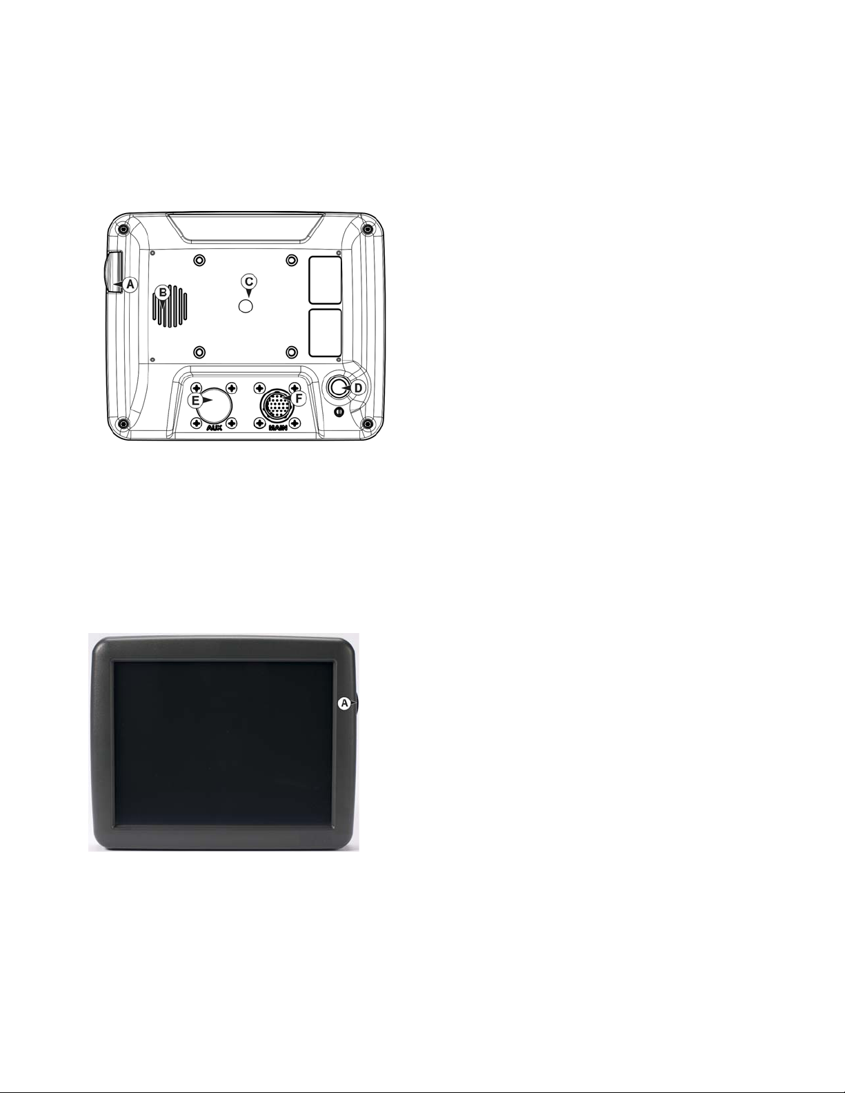
DISPLAY HARDWARE
• (A) USB media slot
Used for data transfer in and out of the display.
• (B) speaker
The built-in speaker is used for audible warnings. The
volume can be adjusted through the display setup routine.
• (C) RAM mount
• (D) Power/Reset switch
The Power/Reset switch is used for turning the display on
and off in installations where the system is connected to a
continuous power supply. If the display ever stops
responding, the manual power switch may be held in for five
seconds to restart the system. Only do this as a last resort,
data loss could occur during times of improper shutdown.
G
ENERAL
I
NSTALLATION
• (E) 28-pin auxiliary connection
Used for camera input.
• (F) 28-pin plug
The 28-Pin round connector contains CAN, RS-232 serial, and system power and ground connections. It is
compatible with other Ag Leader displays. Ether ne t f or ParaDyme and GeoSteer automated steering is
included in connection.
• (A) USB media slot
• Used for data transfer in and out of the display.
INSTALLATION INSTRUCTIONS
All machine installation and mounting kits are shipped with instructions specific to that kit. Instructions
include special details relating to mounting, wiring and display configuration.
Mount the display to a secure support inside the vehicle cab. The following must be considered when
choosing a mounting location:
7
Page 22
• The display must be readily accessible to the machine operator.
• The display must not obstruct the machine operator's normal driving view.
• The display must not interfere with or limit access to any of the existing machine controls.
• The CAN system cabling be routed and secured without interfering with existing machine controls.
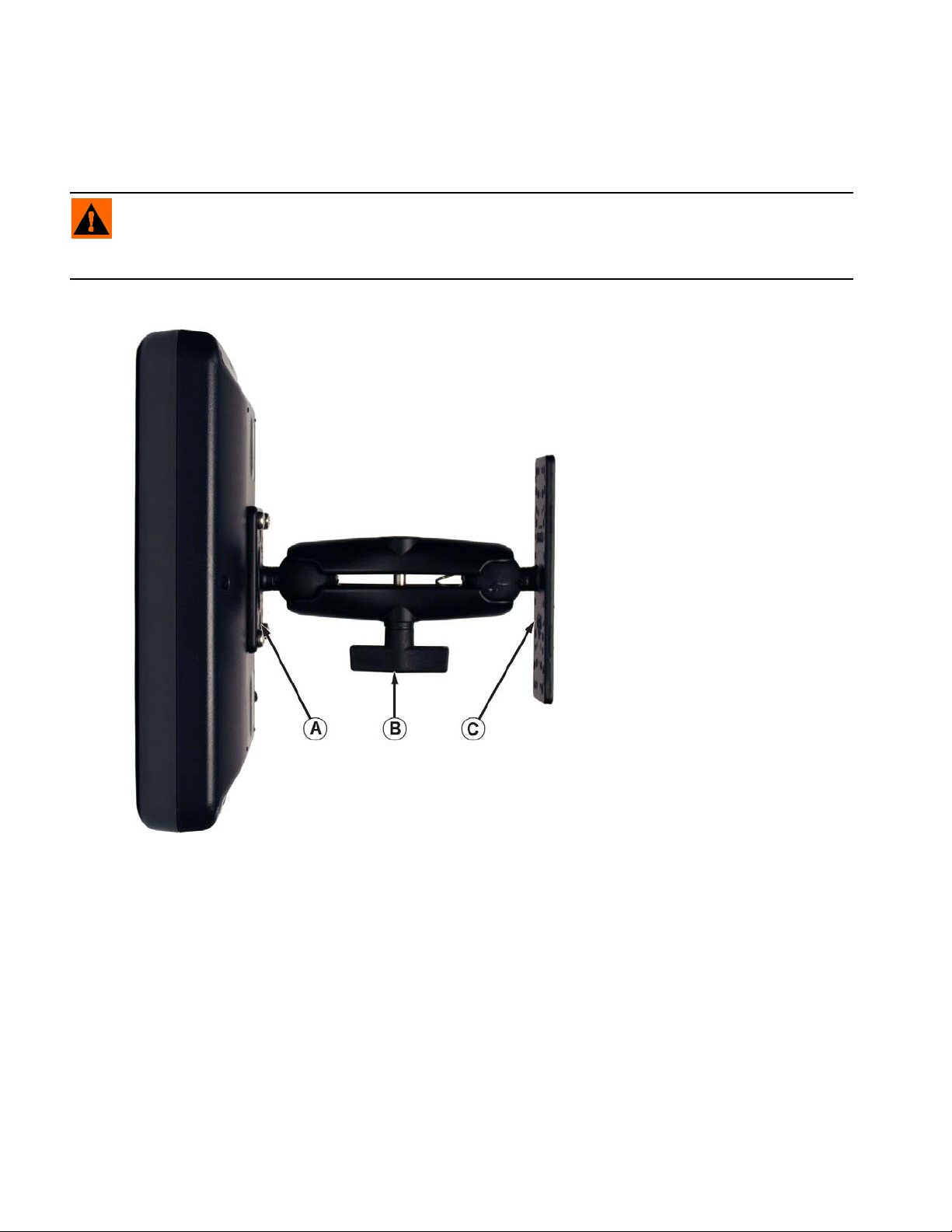
WARNING: If drilling holes is required during the mounting process, care must be taken to insure that
damage is not done to existing vehicle wiring, mechanical, or cab structure. Refer to vehicle manufacturer
documentation for specific details on your equipment. Follow all OEM instructions, cautions, and warnings
when working around equipment.
• (A) RAM Base
• (B) RAM Arm
• (C) Base
8 Firmware Version 5.4
Page 23
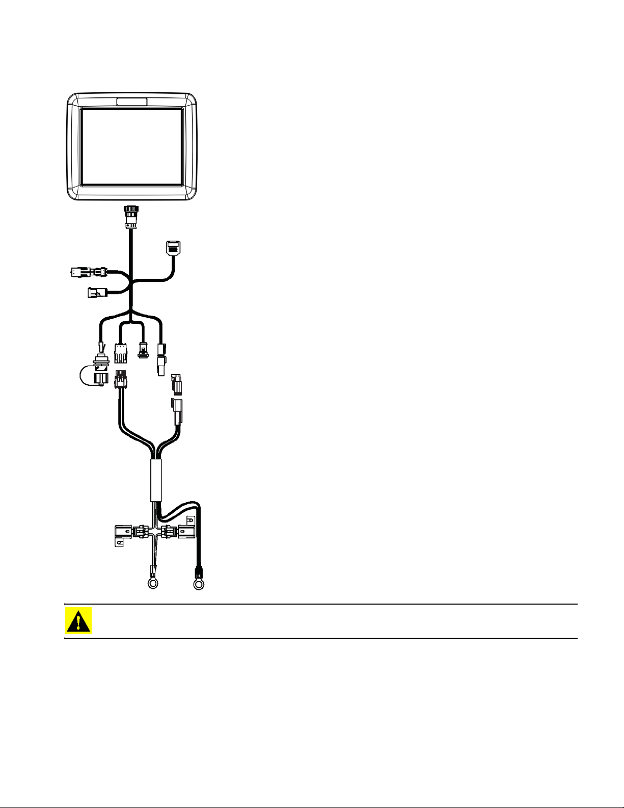
FUSE INSTALLATION AND REPLACEMENT
Fuse Type: Blade Style (ATO/ATC)
Rating:
Fuse Holder (orange wire) 5A, 250 VAC
Fuse Holder (pink wire) 15A, 250 VAC
G
ENERAL
I
NSTALLATION
CAUTION: The fuse is to be placed in the fuse holder in-line with the battery power cable and used with
display only.
SCREEN ICON CONVENTIONS
The following control buttons are made available for entering names and calibration values into the
system.
9
Page 24
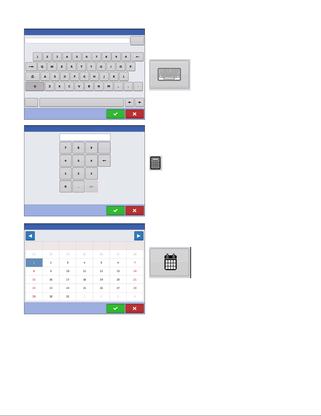
An on-screen Keyboard is made available when
Symbols
Clear
All
Clear
Start Date
March 2015
Sunday
Monday
Tuesday
Wednesday Thursday Friday Saturday
appropriate for use during all setup processes. Press
the keyboard button to access the on-screen text entry
screen.
An on-screen Numeric Keypad is made available for
changing configuration settings and calibration
numbers. Press the keypad button to access the onscreen numeric entry screen.
An on-screen calendar is made available for changing
dates. Press the calendar button to access the
calendar screen.
10 Firmware Version 5.4
Page 25
SETUP
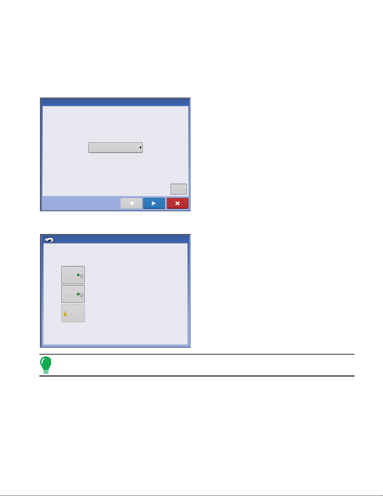
Language Selection
Language
English / US
Advanced
Advanced Options
Restore
Upgrade
Restore data from a backup file (same display model only)
Upgrade the display firmware.
Unlock display features.
Features
Unlocks
SETUP
CONFIGURATION
INITIAL STARTUP
S
ETUP
An Initial Setup wizard is presented on startup.
Once the wizard is completed, it is not shown again
unless the display memory is cleared.
C
ONFIGURATION
ADVANCED OPTIONS
Press “Advanced” button on Language Selection
screen (first screen to appear on initial startup).
• Restore Backup
• Upgrade Firmware
• Unlock Display Features
Note: Using the Restore backup option is not the proper method to get multiple displays set up to
be the same. Use the AGSETUP file.
It is acceptable to complete the initial setup wizard and then upgrade. Setup information will not change.
On a “clean” display going out for service, to stand in for a failed display, the customer should use the
Restore backup option in the initial setup wizard.
11
Page 26
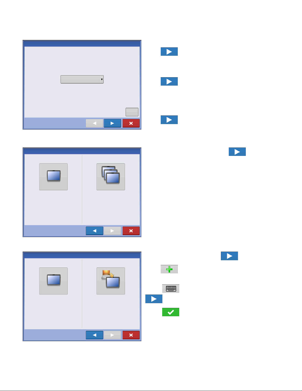
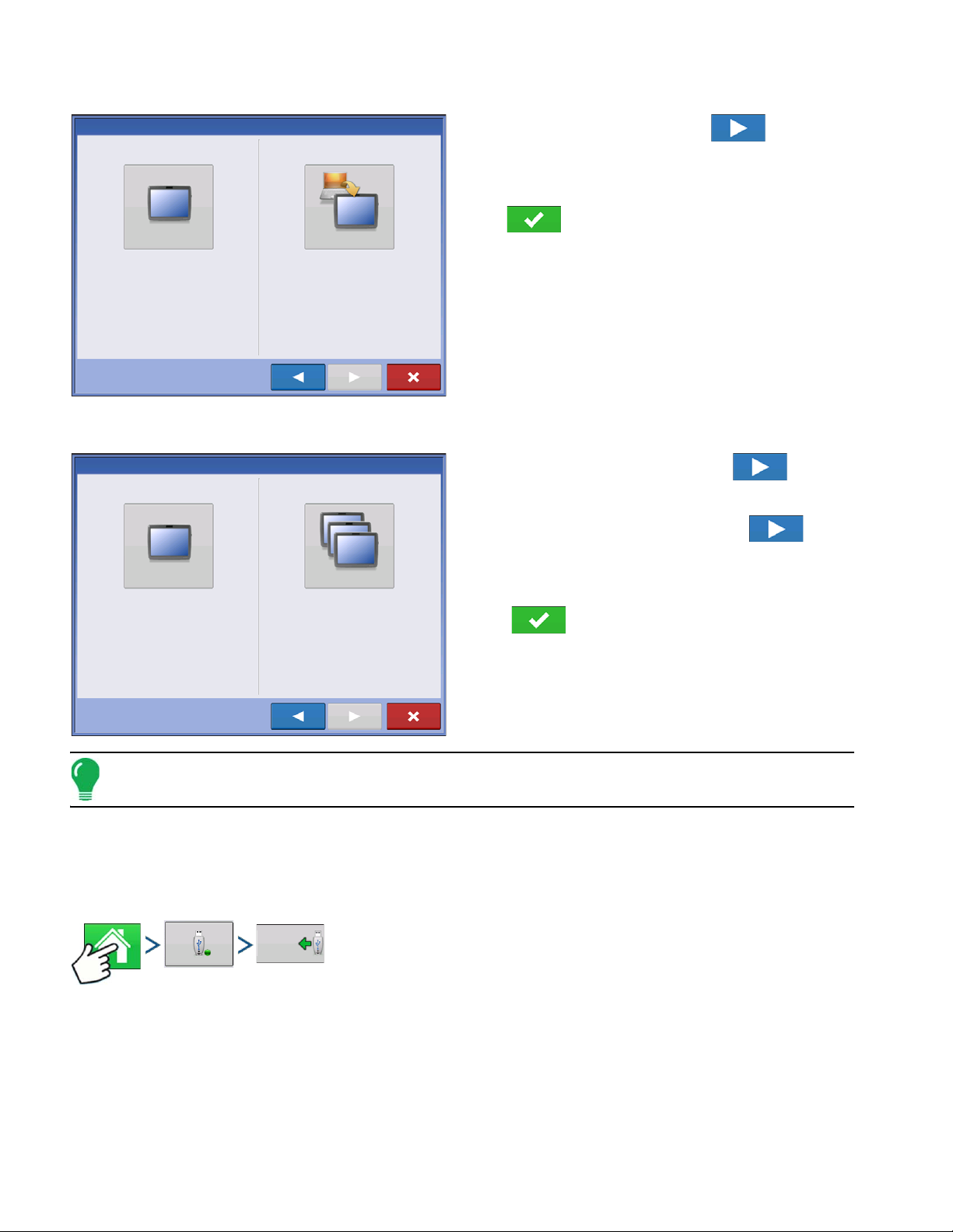
LOCATION SPECIFIC SETUP
Language Selection
Language
English / US
Advanced
Single Display
Multiple Display
Select “Single Display” if you only have one
display in your operation.
Select “Multiple Displays” if you only have more
than one display and want to share setup items
between displays.
New Setup
Import Setup
Select “New Setup” to perform all setup through
the display user-interface.
Select “Import Setup” to select an AgSetup file to
import setup items from your computer.
SINGLE DISPLAY
1. Language
Press to continue.
2. Unit System
Imperial or Metric
Press to continue.
3. Date and Time
Set to GPS Time and Date requires ZDA NMEA
message to be turned on from the GPS receiver.
Press to continue.
Press “Single Display” button then to
continue.
NEW SETUP
12 Firmware Version 5.4
Press “New Setup” button then to continue.
Press to enter a Display Owner (Business
Name).
Press to enter a display nickname. Press
to continue.
Press to accept the setup and return to
Home screen.
Page 27
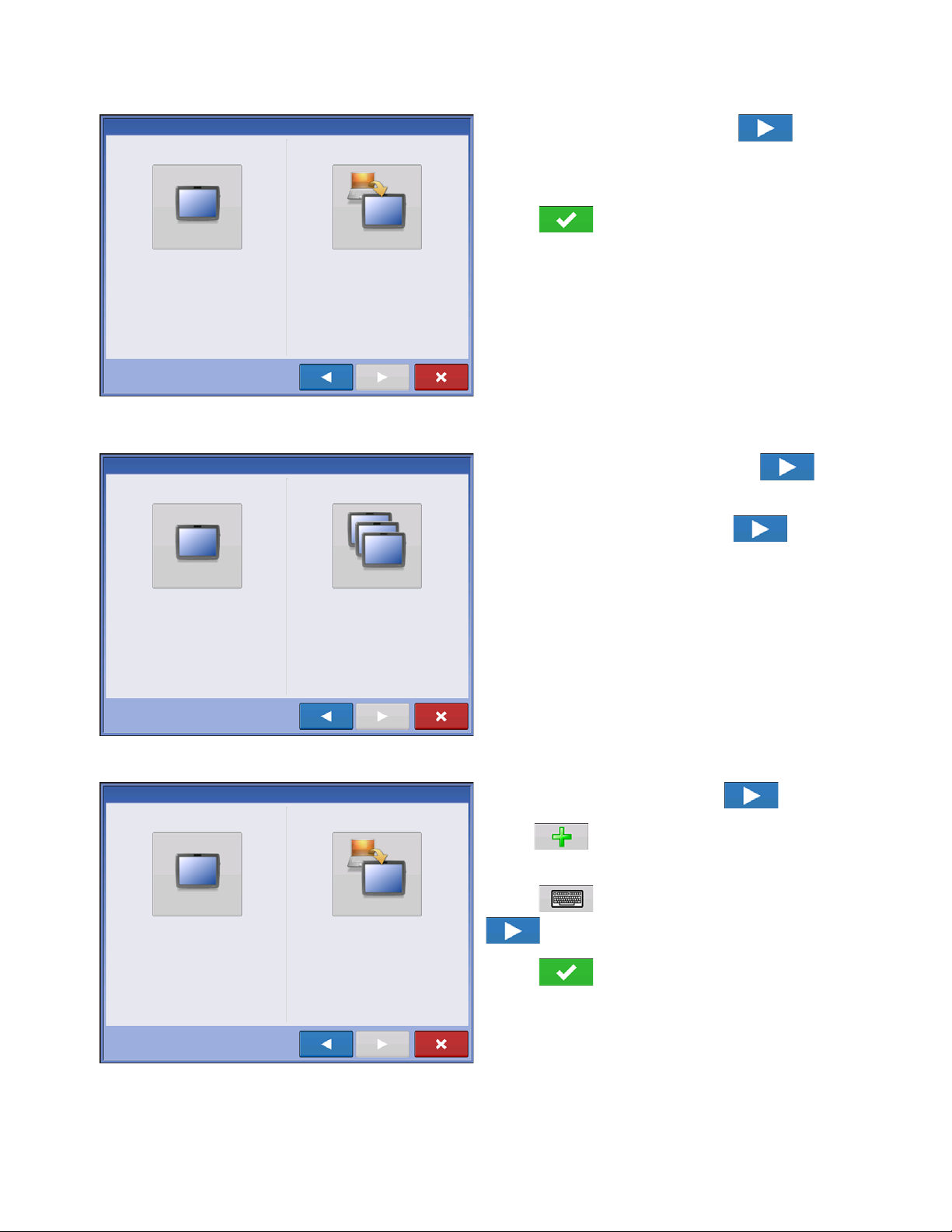
IMPORT SETUP
New Setup
Import Setup
Select “New Setup” to perform all setup through
the display user-interface.
Select “Import Setup” to select an AgSetup file to
import setup items from your computer.
Single Display
Multiple Display
Select “Single Display” if you only have one
display in your operation.
Select “Multiple Displays” if you have more than
one display and want to share setup items
between displays.
New Setup
Import Setup
Select “New Setup” to perform all setup through
the display user-interface.
Select “Import Setup” to select an AgSetup file to
import setup items from your computer.
Press “Import Setup” button then to
continue.
Select desired setup file from directory.
Press to accept the setup and return to
Home screen.
MULTIPLE DISPLAY SETUP - FIRST DISPLAY
Press “Multiple Display” button then to
continue.
S
ETUP
C
ONFIGURATION
NEW SETUP
Press “First Display” button then to continue.
Press “New Setup” button then to continue.
Press to enter a Display Owner (Business
Name).
Press to enter a display nickname. Press
to continue.
Press to accept the setup and return to
Home screen.
13
Page 28
IMPORT SETUP
New Setup
Import Setup
Select “New Setup” to perform all setup through
the display user-interface.
Select “Import Setup” to select an AgSetup file to
import setup items from your computer.
Single Display
Multiple Display
Select “Single Display” if you only have one
display in your operation.
Select “Multiple Displays” if you have more than
one display and want to share setup items
between displays.
Import Files
Press “Import Setup” button then to
continue.
Select desired setup file from directory.
Press to accept the setup and return to
Home screen.
MULTIPLE DISPLAY SETUP - ADDITIONAL DISPLAY
Press “Multiple Display” button then to
continue.
Press “Additional Display” button then to
continue.
Select desired setup file from directory.
Press to accept the setup and return to
Home screen.
Note: The business created on the first display, and any other management and equipment items, will be
imported to the additional displays.
IMPORT SETUP DATA
IMPORT FILES
Press: Home button > External Storage button > Import Files
14 Firmware Version 5.4
Page 29
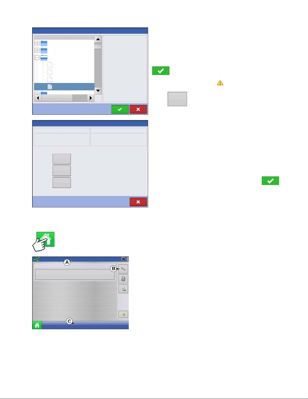
S
No Preview
2009120009-2-634
Demo Waterway
2009120009-2-634
2009120009-2-634
North Field
Waterloo Farm
Davenport Farm
Ashton Farm
Name
Size
File Selection
Resolve
Conflict Resolution
Item to Import
Name:
Modification Time:
Creation Time:
Corn
03/05/2012 14:24
03/05/2012 14:24
Existing Item
Name:
Modification Time:
Creation Time:
01/09/2012 08:35
01/09/2012 08:35
Rename the item being imported.
Rename the existing Item.
Merge the imported and existing items together.
Rename
Imported
Rename
Existing
Corn
Merge
Configuration
Start Field Operation
ETUP
Use the scroll bar to find the file you wish to import.
When a setup file is created it is saved in a folder titled
with the displays serial number _nickname. The file will
include a date and have the .agsetup suffix.
Select the desired setup file from directory and press
.
Highlight item with conflict
Press
Conflicts can be resolved by:
• Rename Import
• Rename Existing
• Merge
- Product Mixes and Configurations can not be merg ed. The
Merge button will be grayed out and not selectable for these
items.
C
ONFIGURATION
HOME SCREEN
Press: Home button
2. Equipment Operating Configuration
For more information, See
You can access Configuration Setup by pressing the
“Management button” on page 30
portion of the Home screen. For more informa tion , see
Once all conflicts have been resolved. press .
Most of the functionality of the display is not available until the
basic setup process is completed.
(A) Status bar
(B) Setup button
(C) Task bar
You must complete these initial configuration steps for the Run
Time Environment to be active:
1. Grower, Farm, and Field management
.
Setup (wrench) button (B)
“Configuration button” on page 21
at the upper right-hand
.
15
Page 30
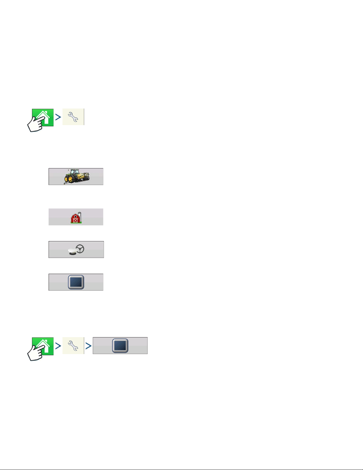
3. Product setup
For more information, see
described in each Operations chapter.
4. Select Event
For more information,
“Product tab” on page 22
“Setup Event” on page 45
, as well as the additional configuration information
.
SETUP BUTTONS
Press: Home button > Setup (wrench) button
The Setup buttons are used to toggle between screens that adjust settings for Configuration,
Management, GPS and display.
• Configuration button
Press to adjust the configuration settings particular to your vehicle and
equipment; as well as enter and edit product informa t ion. For more information,
see
“Product tab” on page 22
, as well as
“Configuration Setup Screen” on page 44
.
• Management button
Press to access and edit Grower , Farm, Field and Operator information. For more
information, see
• GPS button
Press to adjust Guidance settings, GPS settings, and lightbar settings (if
applicable). For more information, see
• Display button
Press to adjust settings for Time and Date, brightness and volume settings,
operating units, language; enable video; view features; and also create and
restore backups.
“Management button” on page 30.
DISPLAY BUTTON
Press: Home button > Setup (wrench) button > Display button
The Display screen contains the following tabs:
“Guidance” on page 107
.
• General tab
displays settings related to Ti me, Date, display screen settings, operating units, video and display owner
information.
16 Firmware Version 5.4
Page 31

S
General
General Display
Features
Advanced
Brightness
100%
Volume
40%
Time/Date
8:56:50 AM
11/01/2011
Time Zone
Americas (Central Time)
Language/Country
English/US
Operating Units
Imperial
Enable Video
Console Setup
Calibrate
Touchscreen
ISOBUS Settings
• Display tab
contains functionality for setting up a Display Owner a nd ma king any needed edits to the owner personal
information.
• Features tab
lists unlocks for a particular display.
• Advanced tab
includes information related to log files and system backups.
GENERAL TAB
Press: Home button > Setup (wrench) button > Display button > General tab
The Setup General Tab is consists of the following
items:
• Time/Date button
ETUP
C
ONFIGURATION
Press button and use
/
to adjust the
hours, minutes, A.M./P.M. settings, month, date and
year. To make these changes effec tive, press .
Note: The display will then shut down immediately. If you do not want to shut the display down, press the
Close (Red X) button; however the time/date changes will not be accepted until the display is shut down and
restarted.
• Brightness and volume percentages.
To change these, press the Brightness/Volume button and use
/
to change the percentage
of the Display Brightness and Speaker Volume.
• Calibrate Touchscreen.
Press this to launch the Touch screen Calibration wizard. Calibrate the touch screen by follow ing the onscreen instructions.
CAUTION: Do not use any sharp objects to operate the touch scree n or the displa y ma y be dama ge d .
• Time Zone
Use the drop-down menu to select your time zone.
• Language/Country Selection
Use the drop-down menu to select the language.
17
Page 32

• Operating Units
Display
Display
Features
Advanced
Phone:
Console Setup
General
Edit
Information
Change
Owner
Nickname: geo
Serial Number: 2009120056
Product Type: AL VERSA
Owner: George Eilers
Phone:
Email:
Address:
Image:
This Display
geo
Features
Select either Imperial or Metric.
• Enable Video
Enables input from up to four video cameras.
• ISOBUS Settings
Enables Virtual Terminal and Task Controller
Must be unlocked
DISPLAY TAB
Press: Home button > Setup (wrench) button > Display button > Display tab
The Display tab contains functionality for setting up a
Display Owner and making any needed edits to the
owner personal information. The Display Owner
information is used in the product application report
feature of application rate control.
• Nickname
• Serial Number
• Product Type
• Owner
• Phone
• Email
• Address
• Image
• Change Owner
• Edit Information
FEATURES TAB
Press: Home button > Setup (wrench) button > Display button > Features tab
18 Firmware Version 5.4
Page 33

S
Features
Advanced
Console Setup
General
Feature
Automatic Swath Control
Multiple Product
Norac UC5 Interface
Fan Frame - Feed Gate Control
Status
Enabled
Enabled
Enabled
Enabled
Feature Description:
Unlock
Enabled
Display
ISOBUS Virtual Terminal
HARDI Sprayer
Off
Advanced
Display
Features
Advanced
Console Setup
General
Log Files
Key Switch Standby
5
About
Memory
Guidance
(minutes)
Export by Grower
Export data files
on shutdown
Export
Diagnostic Files
Restore
Backup
Create
Backup
Export All
Log Files
Advanced
Parameters
Copy
Debug Files
Clear
Debug Files
Clear Internal
Memory
Remove
Patterns
Memory
Tes t
Service
Mode
View Module
Firmware
Unlocking Features
The Features Tab is where you can enter unlock
codes. Unlock codes are unique to the serial number
of each display and the feature registration number.
You must supply these numbers to your dealer when
purchasing any unlock codes. Press to enter
the unlock code and press to enable the
feature.
Note: Once a feature is unlocked, that feature remains with that display and ca nnot be transferred to another .
ADVANCED TAB
ETUP
C
ONFIGURATION
Press: Home button > Setup (wrench) button > Display button > Advanced tab
The Advanced Tab allows you to specify settings for
copying log files; specify Key Switch Standby
settings; view and manually upgrade module
firmware; and create and restore backup files.
CAUTION: The Export Diagnostic Files, Advanced Parameters, Copy Debug Files, Clear De bug Files
and Service Mode functionality on the Advanced Tab is reserved for use by the manufacturer. DO NOT
change any of these settings without specific instruction from the manufacturer.
• Key Switch Standby
This setting allows the display to remain po wered up af ter the veh icle power has b een shut dow n. Instead,
the display will switch into standby mode and will appear to be shut of f; however the powe r light will change
to an amber color. Pressing the touchscreen while it is in standby mode will immediately turn the screen
back on again.
19
Page 34

Use
/
to specify a length of time that you wish the display to remain p owered up in st andby
mode after the vehicle power has been shut down.
Note: When the time you specified in Key Switch Standby is nearly exp ire d , the n the am b er-colore d po we r
light will flash on and off immediately preceding shutdown. If you wish the display to remain powered up for a
longer period of time, touch the display to restart the Key Switch Standby countdown.
• About button
Displays product licensing information and copyright information.
• Log Files
These settings allow you to copy your data in the dis play.
- Export by Grower Press of export log files by growers.
- Export Data Files. Press to copy all logged data in the display to the USB drive.
- Export Data Files on Shutdown. Checking this checkbox will copy all log files to the USB drive when
the display is powering down.
- See “Export Files” on page 66 for more information.
• Memory
Adjusts information stored in the display’s internal memory.
- Create Backup. Press to create a backup file of all configuration settings, products, an d Gro wer- FarmField Management data structure on the USB drive. Backup files are stored using the .ibk2 file format.
- Restore Backup. Press to restore a backup file from the external data drive to the internal memory of
the display.
- Clear Internal Memory. Press this button to clear the internal memory of the display. The system will
present a warning dialog box and ask if you would like to create a backup file prior to clearing the
memory.
CAUTION: Once you clear the system’ s internal memory, this information is deleted and cannot be restored
unless a backup has been made.
• View Module Firmw are. Displays the Module Fir mware Management scre en, which is a list of all firmwa re
modules and firmware versions that ar e available for the display.
Note: The Module Firmware Management list includes module firmware that you may not be running.
- Import - Imports any firmware stored on the USB drive into the display memory.
- Direct Upgrade - Upgrades an individual module directly from the USB.
- Remove - Removes unwanted module firmware from the Module Firmware Management list.
Note: Pressing the Remove button does not remove firmware from the module itself. It merely removes the
upgrade file from the display.
•
Remove Patterns
. Pressing this button permanently erases all guidance patterns from the display’s
memory.
20 Firmware Version 5.4
Page 35

S
Configuration
Configuration Setup
Product
Configuration
Equipment
Name
Equipment
Tillage
JD 8400, JD 2400
Application
JD 4630
Equipment
CONFIGURATION BUTTON
CONFIGURATION TAB
Press: Home button > Setup (wrench) button > Configuration (tractor) button > Configuration tab
The Configuration tab is where you can create, view
and change configuration settings.
An operating configuration is a task-specific
association of vehicle, implement, controller, and
speed source that is saved for use over different
seasons and on different displays.
ETUP
C
ONFIGURATION
• Add button
Press to add an operating configuration. A wizard takes you th rough the process o f creatin g
a configuration.
• When finished, the new configuration appears in the list on the left side of the screen.
• When you highlight the configuration, the equipment in the configuration are listed in the box on the right
side of the screen.
• Information regarding configurations for specific operations is given in each operations chapter.
• Rename button
Press to rename the configuration.
• Setup button
Press to adjust configuration settings.
• Remove button
Press to remove a configuration.
CAUTION: When you remove a configuration all data logged with that configuration will also be removed!
However, all log files will remain in memory until exported to the USB drive.
• Equipment button
Press to add, edit, or remove information for a specific vehicle, implement or cont roller.
21
Page 36

PRODUCT TAB
Product
Configuration
Configuration Setup
Product
Equipment
Manufacturer:
Type:
Units:
Restricted Use:
EPA Number:
Fertilizer
No
Planting
Application
T5423
28% UAN
30% UAN
Ag Lime
CSX56A11VT3PRO
CSX56B10CONV
gallons
Press: Home button > Setup (wrench) button > Configuration (tractor) button > Product tab
The Product tab is where you can add, edit. or
remove product information.
The Product tab is where you can perform the following tasks:
• Add or import Planting products.
• Add or import Application products.
• Add Product Template (such as a tank mix, or a dry blend of mu ltiple products).
• Add or import Harvest products.
• Add button
Press to add or import a Product. At the following screen, choose a Product Option: Add
Product, Import Product, or Add Product Mix (if in Application). From here, an on-screen
wizard continues you through each step of the setup process.
• When finished, the new product appears in Product Tab.
• When you highlight the product, information about the product appears on the right side of the screen.
• Specific planting and application product information can be viewed in those respective chapters.
• Rename button
Press to rename the product.
• Setup button
CAUTION: When you remove a product all regions using that product will also be removed!
Press to adjust configuration settings.
• Remove button
Press to remove a product.
22 Firmware Version 5.4
Page 37

Planting Settings
• Edit Info button
Press to edit the following information for the highlighted prod uct in the Product List.
- Manufacturer
• Edit Legend button
Press to change the legend settings listed below.
- Average
- Range Spacing
- Color Scheme
- Ranges
- Reset to Default Legend
For more information, see
“Legend Settings” on page 52
.
Application Settings
• Edit Info button
Press to edit the following information for the highlighted prod uct in the Product List.
- Product Units
- Manufacturer
- EPA Number
- check box for restricted use pesticides
S
ETUP
C
ONFIGURATION
• Edit Legend button
Press to change the legend settings listed below.
- Average
- Range Spacing
- Color Scheme
- Ranges
- Reset to Default Legend
For more information, see
“Legend Settings” on page 52
.
Grain Harvest Settings
• Crop Settings
Press the Edit button to open the Grain Settings screen where you can adjust the following settings:
- Dry%
- Weight to Volume
- Expand bushels for all grains below dry% If the moisture of the harvested crop is below the dry
• Legend Settings
Choose Yield or Moisture from drop down box.
Press Edit Legend to change the settings listed below.
The percentage of grain moisture used to calculate Dry Bushels
The Weight to Volume conversion number used to calculate bushels.
percentage, the display increases weight to show the weight which would be shown if the
crop equaled or exceeded the dry percentage.
- Average
- Range Spacing
- Color Scheme
- Ranges
- Reset to Default Legend
23
Page 38

For more information, see
“Legend Settings” on page 52
.
24 Firmware Version 5.4
Page 39

SETUP
Guidance
CIH Magnum 180, White 8816
Equipment
Name
Vehicle
CIH Magnum 180
Implement
White 8816
Device
Row Shutoff
Auxiliary Input Module
Row Clutch Control Module
Device
Seed Monitor
Seed Tube Monitor Module
Operating Configuration
CIH Magnum 340, JD1770
Auxiliary Input Module: Not found
Planter Hydraulic Rate Control Module: Not found
Device
Row Shutoff
Auxiliary Input Module: Not found
Row Clutch Control Module: Not found
Seed Monitor
Device
Seed Tube Monitor Module: Not found
Equipment
Name
Operating Configuration
MANAGEMENT SETUP
CONFIGURATION SELECTION
Note:
Configuration Setup is specific to an operation (Guidan ce, T illage, Planting, Application, Harvest) . Go to
the specific operation section in this manual for information on how to setup a configuration.
S
ETUP
M
ANAGEMENT
1. Press the Configuration button on the home page.
Configuration button shows name of current selecte d
configuration. System defaults to guidance configuration.
2. Operating Configuration Selection
Use to select an operating configuration from the drop-down menu.
3. Press to finish Configuration Selection process.
All Modules Detected
Configuration can be loaded and is detecting all
modules setup in the configuration.
Display is detecting the module.
S
ETUP
Modules Missing
Configuration can not be loaded.
Display is not detecting module.
25
Page 40

Some Modules Not Detected
CIH Magnum 340, Hardi Commander 10000
CIH Magnum 340
Hardi Commander 10000
DC COM10K
Auxiliary Input Module
Liquid Control Module
Name
Equipment
Container
Main Tank
Device
DL1
Auxiliary Input Module
Direct Injection Module: Not found
Container
Injection Tank
Device
Crop Sensor
Crop Sensor Master Module: Not found
Device
Boom Control
Norac UC5 Controller Modu le: Not found
Vehicle
Implement
Device
Operating Configuration
JD 8235R, Appl
Equipment
Vehicle
JD8235R
Implement
Name
Appl
Device
DirectLiquid
Auxiliary Input Module
Liquid Control Module: Serial number does not match expected.
Container Main Tank
Operating Configuration
The selected configuration contains a
module that appears to have been replaced.
If this is the case, press accept. Otherwise,
press cancel and choose or create another
configuration.
Module Changed/Missing
Configuration can be loaded but is not detecting all
the modules associated with the configuration. When
loaded, it will not perform the functions of the missing
modules.
Display is detecting module.
Display is not detecting module.
An example of an application configuration is shown.
The Direct Command module is detected by the
display but the Direct Injection, Crop Sensor, and
Boom Control modules are not.
Modules not the same as previously used
26 Firmware Version 5.4
Configuration has a module that was not used
previously.
Module is not the one that was previously used.
If an operator selects a configuration that has a , the Module
Changed/Missing window will appear, verifying that you want to load the
configuration. If you press , the configuration will be updated with
the modules currently being used.
Page 41

S
Users
Select Specific
User
Edit User
General
Phone/Email
User Role
Operator
Manager
Address
Permission Level
Custom
Management
Field Management
View Summary
Mapping
Pan/Zoom Controls
Legend Toolbox
Marks Toolbox
Permissions
Management
Field Management
View Summary
Management
Field Management
View Summary
ETUP
EVENTS
Events are used to track field operations. New events can be created at anytime and therefore a
physical field can be broken into many events or recorded under one.
An event contains all coverage maps created while that event was active. Events are automatically
named by date and time.
The display can be run in two different modes:
M
ANAGEMENT
Traditional mode: requires user to specify a Grower, Farm, and Field for the Event. The display
associates this information with setup files and logged data. When these files are reviewed or utilized in
the future, it provides the operator with a greater depth of information.
Events Only mode: minimizes the setup process so that the display is ready to run in the field with the
least amount of setup (just a few button presses).
Setting mode (Traditional or Events Only) using Permissions
The display is set to Traditional mode by default but Events Only mode can be enabled by de-selecting
“Field Management” in a user’s permissions.
Management (Barn) button > User tab > Select Specific User > Setup (wrench) button
Edit User screen allows permissions to set for
user.
S
ETUP
Display uses Traditional mode when Field Management is checked. Events using
the Traditional mode are tied to the Grower/Farm/Field structure.
Display uses Events Only mode when Field management is unchecked.
27
Page 42

Starting an Event
Select Event
2014 Crop
Growing Season
Grower
George Eilers
Farm
Sheldon
Field
Management Selection
Enable Management
Orab
Enable Management
Enable Management
Pattern Options
New Guidance Pattern
Change
Pattern
Implement Width:
Guidance Width
30.0000
30.0000
Enable Tramlines
Straight
Event: 2014-01-09_14:40:42
Grower: George Eilers
Farm: Sheldon
Field: Orab
1. Press: Select Event button.
Select a Season, Grower, Farm, and
Field on the Management Selection
screen.
Note: This screen does not appear when operating
in Events Only mode.
Enable Management button
is checked by default and requires a Grower, Farm,
and Field to be entered before proceeding.
To create a Grower, Farm, and Field press the
button on current screen and press
again next screen. Then type in name and press
twice.
Grower, Farm, and Field can also be created in
tab” on page 30
screen without entering additional information on this screen (similar to Events Only mode).
Edit Event Name, Suspend Event, and Clear Map Bounds
28 Firmware Version 5.4
Managing Events
Management setup . See
to set up information using Management setup.
Un-checking Enable Management button will allow operator to continue to next
Next screen will vary depending on configuration.
For Example:
The screen shown to the left will appear for
Guidance configurations.
For Application configurations the screen will involve
product selection.
For Seeding configurations the screen will involve
seed selection.
Make selections and press to continue.
Map screen will appear and user can begin
operation.
“Grower/Farm/Field
Press Setup
button (wrench)
on Event bar.
Page 43

Select a Previous Event
Event Options
Suspend
Event
Event Name
014-01-10_08:3:31
Clear
Map Bounds
Event: 2014-01-09_14:40:42
Grower: George Eilers
Farm: Sheldon
Field: Orab
2014 Crop
Growing Season
Grower
George Eilers
Farm
Sheldon
Field
Management Selection
Enable Management
Orab
Event Selection
New Event
2014-01-12_16:01:17
2014-01-12_15:54:14
Corn
S
ETUP
The Event Options screen allows operator to change
the Event name, Suspend Event, and to Clear Map
bounds.
Press event
name on Event
bar.
M
ANAGEMENT
S
ETUP
Note: This screen does not appear when operating
in Events Only mode.
Management Selection screen appears.
Press to accept.
The Field Operation Wizard: Event Selection screen
allows the operator to pick a previously created
event.
Press to accept.
29
Page 44

MANAGEMENT BUTTON
Grower/Farm/Field
Press: Home button > Setup (wrench) button > Management (Barn) button
From this screen the operator can access Grower/Farm/Field, Season, User, and Businesses tabs.
GROWER/FARM/FIELD TAB
Press: Home button > Setup (wrench) button > Management (Barn) button > Grower/Farm/Field tab
Grower
The Grower refers to the business or person that the system is in operation for. Contact information can
also be entered for each Grower. The Grower information will be passed into mapping software for
automatic Grower setup within desktop software.
• Add button
Press to add a Grower.
• Rename button
Edit an existing name of a Grower by highlighting that name and pressing button.
• Setup button
Press to enter information for the Grower’s Name, Tax ID and Memo.
• Remove button
Press to remove a Grower.
Note: Personal Information entered at this screen can be added or edited at any time.
30 Firmware Version 5.4
Page 45

Farm and Field
Grower/Farm/Field
Season
Users
Contacts
Grower: Gene Eilers
Farm: Sheldon
Grower: Seth
Field: Low 80
True Area:
Boundary
Management Setup
Clear
40 ac
39.92 ac
Businesses
Low 80
Sheldon
Field
Area
County
Township
Range
Section
FSA Number
FSA Area
Legal Description
Farm
Clear
Bounds
Field Information
0 ac
0 ac
• Add button
Press to add a Field.
• Rename button
Edit an existing name of a Field by highlighting that name and pressing button.
S
ETUP
In the display, farms are subdivided into fields. You
can associate Field names with a particular Grower. If
the display will be used for multiple Growers, enter
each Grower business name and associate the field
names with the correct grower when the fields are set
up within the system.
In the Field Tab, select a Grower underneath the dropdown menu at the top. Each farm of that particular
grower is shown in a list, with the fields within that farm
as subcomponents within that list.
M
ANAGEMENT
S
ETUP
• Setup button
Edit the Farm and Field information by highlighting that name and pressing button. The Field
Information screen appears.
• Remove button
Press to remove a Field.
The Field Information screen opens, showing the
name of that field in the Title Bar. Field Name
information that can be added or edited by pressing
including Farm, County, Township, Range,
Section Number, Area, FSA Number, FSA Area and
Legal Description.
• Area
shown in the total acres (hectares) of the field.
• FSA Number
refers to the U.S. Farm Service Agency’s four-digit number assigned to every field.
• FSA Area
refers to tillable acres as established by the FSA.
31
Page 46

• Clear Bounds button
Grower/Farm/Field
Season Users
Contacts
Grower: Gene Eilers
Farm: Sheldon
Grower: Seth
Field: Low 80
True Area:
Boundary
Management Setup
Clear
40 ac
39.92 ac
Businesses
File Selection
Name
Boundaries
New Folder 1
Field_1.iby
Field_2.iby
Field_3.iby
Field_4.iby
irx_multi_product
irx_single_product
Field:
Farm:
Grower:
Demo
Allegon County
Michigan Test Fields
91.51 ac
Press to center the map on the current GPS position.
Note: The Clear Bounds feature is particularly useful if you have flyer points or have logged a point outside
the mappable range of your current location.
Importing and Exporting Field Boundaries
Boundaries can be created with the display or imported from desktop GIS software. Any boundary files
present in the display can also be exported for use in desktop mapping software.
Note: For more information on creating boundaries, see “Create Boundary” on page 55.
• USB Import button
To import a boundary from the USB drive, first go
to the Setup Field tab, highlight th e correct field in
the Farm/Field list and press the USB Import
button.
The File Selection screen appears. Highlight the
desired file to import.
Operator can import/export all fields and boundaries
at once with an .AGSETUP file. For more
information on .AGSETUP files see
on page 283.
See “.AGSETUP”
Press to complete the import process.
A screen will appear telling you that the boundary was exported successfully. Press return to the
field setup screen.
32 Firmware Version 5.4
• USB Export button
To export a boundary to the USB drive, highlight the correct field in the Farm/Field list and
press the USB Export button. At the File Selection screen, highlight the desired field to export.
Page 47

S
Season
Users
Grower/Farm/Field Season
Users
Eilers, George
Eilers, Joan
Schmidt, Jack
Oakes, Bill
Management Setup
Businesses
VanBurkum, Doug
ETUP
SEASON TAB
Press: Home button > Setup (wrench) button > Management (Barn) button > Season tab
A season is defined as the calendar year that the crop will be harvested. A season has a start and an
end date. Creating a season and setting it to active is required prior to the system logging any data.
The seasons are displayed in lists, with the Active season displayed in bold face type. All new data is
logged to the active season; therefore a season must be set as Active before you can log any new data
to it.
• Add button
Press to add a Season.
• Edit button
Edit an existing name of a Season by highlighting that name and pressing button.
• Set Active button
Press to set the season selected in the Summary list box to the active season.
M
ANAGEMENT
S
ETUP
USERS TAB
Press: Home button > Setup (wrench) button > Management (Barn) button > User tab
• Season Reminder button
Press to set the date that the system will prompt the operator to create a new season.
• Remove button
Press to remove a season.
Management Setup screen - User tab allows user to
add, modify, or delete users from the display.
33
Page 48

Add a User
Users
Users
Select Specific
User
Press: Home button > Setup (wrench) button > Management (Barn) button > User tab > Plus (+) button
1. Enter first name and/or last name (have to enter a first or last name, recommend entering both)
2. Enter applicator license (optional). Press to continue.
3. Select Operator or Manager (can select either, none, or both). For more information on selecting
Operator/Manager and setting up permissions, see
“Permissions” on page 35. Press to continue.
4. Enter and verify password (optional)
• Locks the displays ability to load/change operating configurations, access setup and USB, if Manager has
a password set
• Leaves display unsecure unless each manger sets a password
• Warning message appears if passwords do not match
• No restriction for password format (can be any combination of letters, numbers, and special characters)
• Case sensitive
5. Press to accept
• Setup button
Press to edit operator information by highlighting that name and pressing button . Setup button
allows user to edit information originally entered when profile was added. Edit button also
allows access to more phone, email, and address information.
• Remove button
Press to remove an operator.
User Setup button
Press: Home button > Setup (wrench) button > Management (Barn) button > User tab > Select Specific
User > Setup (wrench) button
34 Firmware Version 5.4
Page 49

S
General
Phone/Email
Address
Operator
Manager
Full Permission Level
Edit Person
Permissions
Full
Permission Level
General
Phone/Email
Address
George
Eilers
Passwor
First
Edit User
Permissions
Applicator License
Last
Memo
Set Password
Clear Password
ETUP
M
• Business Email
Address tab
• Address
• Extended Address
• City/Locality
• State/Province
General tab
• First and Last Name
• Set and Clear Password
• Applicator License
• Memo
Phone/Email tab
• Home Phone
• Mobile Phone
• Business Phone
• Home Email
ANAGEMENT
S
ETUP
• Country
• Postal Code
PERMISSIONS
This is an optional function that defines what access the user will have in the display. Users are defined
as Operator or Manager (can select either, none, or both).
Ope
rators
• Have full or limited access
• No access to USB or Setup options, unless also set as
a Manager
- Can import from USB from Map Screen (RX, patterns,
boundaries)
• Manager sets up privileges
Managers
• Full access to the display settings and functions
System can be set up with operators only. Passwords are not used when set up this way.
• Only user that can change the selected configuration
• Ability to log out of the display
35
Page 50

PERMISSION LEVEL FOR OPERATORS
Full Permission
Provides full access to features and functionality on the map and home screen. A user, set only as an
Operator, cannot select a different configuration and cannot access USB or Setup, when a manager is
setup in the display.
Basic Permission
No access to:
• Summary screen
• Legend Tab on Map screen
• Marks Tab on Map screen
• Boundary Tab on Map screen
Limits Guidance options to:
• Creating & loading Straight AB or SmartPath patterns
• Nudge
• Remark A
• Save or reset guidance line
36 Firmware Version 5.4
Page 51

Custom Permission
General
Phone/Email
Address
Operator
Manager
Management
User Role
Edit User
Permissions
Custom
Permission Level
Mapping
Patterns
View Summary
Pan/Zoom Controls
Legend Toolbox
Boundary Toolbox
Guidance Toolbox
Minimize Toolboxes
Straight AB
SmartPath
Pivot
Adaptive Curve
Identical Curve
A + Heading
Tramlines
Nudge
Shift
Remove Patterns
Field Management
Management
Field Management
View Summary
Management
Field Management
View Summary
Can allow or deny the following options:
• Management screen
• Pan/Zoom controls
S
ETUP
M
ANAGEMENT
• Legend Toolbox
• Marks Toolbox
• Boundary Toolbox
• Guidance Toolbox
• Minimize Toolbox
• Each individual guidance pattern
• Ability to remove guidance patterns
Display uses Traditional mode when Field Management is checked. Events using
the Traditional mode are tied to the Grower/Farm/Field structure.
Display uses Events Only mode when Field management is unchecked.
Management, GPS/Guidance, Console Setup, and External Storage Buttons are locked for
Operators.
A manager can access these buttons by pressing the button and inputting their password.
A User can be setup as an Operator and Manager to have the same access as a Manager.
S
ETUP
37
Page 52

Setup and USB buttons are locked for Operators if a Manager is present in the system. A
0.67 ac
4.5 mph
Guidance
1
New
Pattern
Load
Pattern
Manage
Patterns
Manager can access setup menu and USB by pressing button and inputting their
password.
A User can be setup as an Operator and Manager to have the same access as a Manager.
The Home and Map screen will appear different depending on how you assigned user permissions. For
setting up users with permissions see
“Users tab” on page 33.
Basic Permissions - Home screen
• No Summary screen
• Setup and USB buttons are locked (as indicated by a p adlock icon on those buttons)
• Brightness and volume are on home screen - settings saved per operator
• Operator Change - Option to continue or start n ew operation when operators change
Full Permissions - Home Screen
• Summary screen button is present
• Setup and USB are locked
• Management, GPS/Guidance, Console Setup, and External Storage Buttons are locked for
Operators.
• A manager can access these buttons by pressing the button and inputting their password.
A user, set only as an Operator, cannot select a different configuration, when a manager is setup in the
display. When a manager is setup in the display, only a managers can unlock and change the
configuration so the manager should make sure to select a configuration upon setup.
Map screen appearance of an operator
with Basic permission. Only the
Guidance toolbox is present.
Operator can
• Create guidance lines
- Straight AB
- SmartPath
• Nudge
• Guidance setup
38 Firmware Version 5.4
Page 53

ACCESSING SETUP MENUS
1. Press Setup (wrench) button.
2. Select Manager from drop-down menu. Press .
3. Enter password. Press .
Now have complete access to the setup menus:
• Configurations Settings
• Grower management
• GPS settings
• Display settings
Do not have to be a Manger to create certain objects
• Grower
• Farm
• Field
• Product (can't change units)
ACCESSING USB
S
ETUP
M
ANAGEMENT
S
ETUP
1. Press USB button
2. Select Manager from drop-down menu. Press .
3. Enter password. Press .
Now have complete access to the USB functions:
• Import/export
• AgSetup files
• Export data
• Upgrade firmware
• Advanced options
Advanced Options with USB
• Ability to create/restore backups from USB
• Options for exporting log files
- Export by grower
- Export data at shutdown
- Export all log files
FORGOTTEN PASSWORDS
When a Manager forgets his password he won't be able to access Setup.
Tech Support will be able to generate a password based on the serial number and firmware of the
monitor.
39
Page 54

Password generator will require the following
Firmware: 4.0.18/4.0.17
Firmware ID: VERSA
Hardware ID: 4001683
Product ID: VERSA
Serial Number: 2009120056
Revision: 4.3.2.0
Run Time: 436:54:39
Boot Counter: 394
DISPLAY
CAN A
CAN B
Devices
Diagnostics
Businesses
information:
• (A) Display serial number
• (B) Major revision
- First digit of firmware version
• (C) Minor revision
- First digit of firmware version after decimal.
Example:
Version 4.5
Major = 4
Minor = 5
Only needed when a Manger forgets their password and works within the display until firmware is
upgraded.
How will Tech Support identify if the person calling in is a Manager or not?
They will ask the caller, “Are you a Manager in the display?” If the customer answers yes, Te ch Support
will generate the password. If the customer answers no, Tech Support will require a Manager to
authorize the display to be unlocked.
What if a customer doesn’t want to risk forgetting passwords and generating new ones?
A display does not need to be locked with a password. The display can be operated as it has been in the
past without passwords. Operators can also be setup with limited or customized access without
passwords.
Tips
• Managers, keep a record of all passwords set in the display.
• Operators, write down your personal password.
• To avoid Operators obtaining unwanted access to a displa y, instruct them to call a Manager for help with
passwords before Tech Support.
BUSINESSES TAB
Press: Home button > Setup (wrench) button > Management (Barn) button > Businesses tab
The businesses are displayed in lists, with the Active business displayed in bold face type. All new data
is logged to the active business; therefore a business must be set as Active before you can log any new
data to it.
• Add button
Press to add a business
• Edit button
Edit an existing business by highlighting that name and pressing button.
40 Firmware Version 5.4
Page 55

• Remove button
Press to remove a business.
S
ETUP
M
ANAGEMENT
S
ETUP
41
Page 56

42 Firmware Version 5.4
Page 57

SETUP
JD 8360R, JD 1770
Eilers, George
Event: 2014-01-09_12:39:39
0 sds/ac
0 sds/ac
0 sds/ac
0.0 sds
0.0 sds
0.0 sds
0.0 ac
0.0 ac
0.0 ac
1222
C1224
C1492
Products
Productivity
Field: Orab
Region:
<1>
Select Operator
FIELD OPERATIONS
A. Operator Selection, see “Operator Selection” on page 43
B. Edit Operator, see “User Setup button” on page 34
S
ETUP
F
IELD
O
PERATIONS
C. Operating Configuration, see “Configuration Selection” on page 25
D. Configuration Setup, see “Configuration Setup Screen” on page 44
E. Event Setup, see “Setup Event” on page 45
F. Event Options, see “Field Operation Options” on page 46
G. Products Tab, shows products, rates and area covered
H. Product Selection, press to change products
I. Rate Control Settings, press to change rates
J. Productivity Tab, shows speed, time, area covered, and distance traveled
K. Region Options, see
“Region button” on page 46
OPERATOR SELECTION
1. Press Select Operator button
Allows you to select a machine operator from the drop-down
list. Machine operator information is logged with all field
operations.
Operator information may be entered in Manage ment Setup at
“Management button” on page 16
43
Page 58

2. Choose the operator from drop-down menu.
Operator Selection
Options
Select Operator
Eilers, George
Show Operator Selection on Startup
Note: If the active operator has a password, the
operator selection will always be displayed on startup.
Log Out
Guidance
Note: Checkbox will require a password to be
entered upon start up of the display.
Press .
3. Enter password. Press .
The operator will now be selected and permissions
active
OPERATOR LOG OUT
Press: Home button > Operator: button > Logout button
Users that are both a Manager and Operator can logout which locks Setup and USB access and an
operator must log in before an operation can be performed.
CONFIGURATION SETUP SCREEN
The Configuration Setup screen is where you can make settings adjustments for your equipment,
ground speed, GPS, and controllers.
The appearance of this Configuration Setup screen varies, based on your particular configuration. Some
DirectCommand and SeedCommand configurations include settings that are mentioned in those
individual chapters. Most Configuration Settings screens will include the following buttons.
•
Equipment Settings.
•
Speed Input
•
AutoSwath
•
GPS Offsets
•
Swath Section Offsets
•
Controller Settings
. For more information, see
. For more information, see
. For more information, see
chapters.
For more information, see
“Speed Input Settings” on page 72.
“AutoSwath” on page 76
“Vehicle Offsets” on page 77
. For more information, see
“Equipment Settings” on page 71
.
.
“Swath Section Offsets” on page 78
.
.
. For more information, see information in the SeedCommand and DirectC ommand
•
Calibrate Pressure
44 Firmware Version 5.4
. Used in DirectCommand Liquid Application configurations.
Page 59

SETUP EVENT
Select Event
Product Selection
DC COM10K
DL1
Crop Sensor
Boom Control
Active
Active
Active
Select Product
Active
28% UAN
S
ETUP
F
IELD
You must have already created the following:
• A
Season, Grower, Farm
button” on page 30.
• An
Operating Configuration
and
Field
in Setup Management. For more information, see
“Management
at the Setup screen’s Configuration Tab. This Operating Configuration
consists of Equipment, V ehicle, Implement, Controller (o ptional), Container (in Application ), and Ground
Speed So urce.
• A
Product
more information, see
(if you are creating an Application or Planting Field Operation) at the Setup Product Tab. For
“Product tab” on page 22
.
All of these are referenced by the Field Operation Wizard during the Field Operation setup process.
Press the “Select Event” button
and follow the steps in the wizard.
Select Event button opens the Field Operation Wizard where you can enter information relating to your
Growing Season, Grower, Farm, Field, Crop Type and Product. For more information, see
on page 45
and also “Field Operation Options” on page 46.
“Setup Event”
1. Grower, Farm and Field Selection
Enter a Growing Season, Grower, Farm, and Field by pressing to select existing ones from a dropdown menu, or by pressing to create a new one.
O
PERATIONS
Use to select an operating configuration from the drop-down menu. For more informations on
Configuration Selection see
“Configuration Selection” on page 25.
2. Product Selection
A planting or application configuration must include a product. Select product from the drop-down list or
press to create a new on e.
Press to continue.
• If a configuration is loaded with undetected
modules, the Product Selection screen may show
some grayed out (unavailable) options. The
example to the left shows that the Direct
Command module is active but Direct Injection,
Crop Sensor, and Boom Control modules are
grayed out and not functional.
3. Region Options
Press
to edit or change the region name from the system default if desired. At this screen, you can
also create a new region or change the controlling product.
45
Page 60

4. Return to Home screen
Region:
<1>
Event: 2014-01-09_14:40:42
Grower: George Eilers
Farm: Sheldon
Field: Orab
Event Options
Suspend
Event
Event Name
2020-01-10_08:3:31
Clear
Map Bounds
Close
Event
Prompts to
Close Event
When you complete the steps in the Wizard, you will return to the Hom e scre en.
• For information on Run screen operations, see
“Run screens” on page 47
.
FIELD FINDER
If you have an existing field boundary, and your current GPS position is within that field boundary, the
display will automatically pick the correct Grower, Farm and Field combination when you start a Field
Operation.
• Region button
A region is used to subdivide a field into smaller sections. The region in which data
is currently being logged is listed on the Region button. A new region can be created at any time as you
are performing a field operation.
To change between or add a new region to a field, press the Region button and follow the on-screen
instructions.
• Field Notes button
Edit any of the report items that are listed in Smart Report™. For more information, see
“Smart Report™” on page 66
.
FIELD OPERATION OPTIONS
During a field operation, you can suspend or close the event by pressing on the wrench at the end of the
Grower Farm Field (Select Event) button. This opens the Events Options screen.
Press Setup
button (wrench)
on Event bar.
The Event Options screen allows operator to change
the Event name, Suspend or Close Event, be
Prompted to Close the Event, and to Clear Map
bounds.
A closed event cannot be re-opened and will not
show up in the Event Selection screen. A user can
manually close Events or be prompted to close
events.
46 Firmware Version 5.4
Page 61

RUN SCREENS
40 ft 0 in
sds/ac
Corn
Varieties
C1420
Planter Drives (rpm)
1
75
Flow 12864 sds/min
100%
1.97
C1420
32000
32000
32000
30000
1
2
S
ETUP
F
IELD
• (A) Status Bar
• (B) On-screen Light bar
• (C) Mapping toolbox
• (D) Mapping Function tabs
• (E) Product Control toolbox
• (F) Product tabs
• (G) Function buttons
• (H) Task bar
• (I) Main Screen buttons
• (J) Equipment tab
The appearance of the Map screen varies, depending upon which operation you are performing, and
your specific operating configuration.
The task bar displays buttons relating to various functions of the display. These buttons and status
indicators include Home, Mapping, Autoswath, Logging, and Auxiliary Input Status. These buttons are
shown in front of a green background when you are at that screen; otherwise they are shown in front of
a blue background.
O
PERATIONS
Home button - Pressing the Home button takes you to the Home screen.
Map button - Pressing the Map button takes you to the Map screen. Pressing it more than once cycles
the Map screen to zoom in and out.
ZOOM DETAILS
ZOOM TO EXTENT
PERSPECTIVE VIEW
Note: The Perspective View is only available when guidance is active.
Video button. Pressing this button takes you to the video screen. Pressing this button
repeatedly cycles through the video inputs.
47
Page 62

Note: For more information on the Video screen, see “Video” on page 62.
AutoSwath button. Pressing this button turns the AutoSwath feature on and off. When AutoSwath is
on, the icon is green; when it is off the icon is white.
AutoSwath - ON
AutoSwath - OFF
Area Logging Status button - This button appears for configurations that do not use rate control, such
as Tillage, Harvest, Planting operations that do not use SeedCommand, and Application operations that
do not use DirectCommand. Pressing this button turns logging on and off.
ON
OFF
The NORAC Engage button enables boom height control. This button can toggle back and forth
between Automatic Mode and Manual Mode.
When you enable Automatic Mode, this button turns green with three lines appearing underneath the
triangle. At the same time, the display beeps three times.
When you disable Automatic Mode on any part of the boom and the display switches to Manual Mode,
this button turns gray and the display beeps twice. If less than the full boom remains in Manual Mode,
the display will continue beeping twice every three seconds.
NORAC Engage - Enabled
NORAC Engage - Disabled
The Engage icon shows that the autosteer system is on, off, or off but ready to engage. The appearance
of this icon displays the following:
Engage - ON
Green if the autosteer system is on.
Engage - Ready
Grey if the autosteer system off but ready to engage.
48 Firmware Version 5.4
Page 63

S
Engage - Not Ready
Grey with a red circle and slash if the autosteer system is off and unable to engage.
ETUP
F
IELD
Note: For more information, see “Guidance” on page 107.
Master Switch Status. This bar shows that the Master Switch is active.
Master Switch - ON (GREEN) Master Switch - OFF (RED)
GPS SIGNAL INDICATOR
The GPS button in the upper left-hand corner of the Map screen, displays the following colors:
Differential GPS
Green if you are receiving a differential GPS signal
GPS - No differential
Yellow if you are receiving GPS, but no differential signal
No GPS
O
PERATIONS
Grey if you are receiving no GPS signal.
The Flex Mode icon appears for ParaDymes and GeoSteers using Flex Mode. Flex mode provides
continuity of position solution to maintain automated steering by seamless flexing (transitioning) to a
lower accuracy mode when a higher accuracy mode is lost; such as loss of the RTK radio link.
Flex Mode - ON (GREEN)
Flex Mode - Exceeded (YELLOW)
Note: For more information, see the ParaDyme Insert.
The Device Information button opens screens that display Device Information, Memory,
Display, and display diagnostics.
Note: For more information, See “Device Information” on page 69.
49
Page 64

Vehicle Icon - Zoom to Extent
The Vehicle Icon is shown by an arrow inside a circle if the Map screen is viewed in Zoom to
Extent.
The vehicle appears as a gold-colored triangle if the Map screen is viewed in Zoom Detail. The
appearance of the zoomed-in icon changes depending upon the data being logged in the field.
Vehicle Icon - logging
If the vehicle is logging, the implement icon appears as a green bar behind it.
Vehicle Icon - with sections
If the vehicle is logging data from an implement split into sections, (for instance during a
planting or application operation), then these sections appear in the implement icon.
Vehicle Icon - not logging
If the vehicle is not logging data, then the implement icon appears as a gray bar.
Press the grid area of the Map screen, and four arrow icons appear at the
bottom right of the Map screen. An example showing these arrow buttons is
at left. Pressing these arrow icons will move the center of the Map screen in
the direction of the arrow button.
The Zoom Tool icons, which resemble a magnifying glass, are shown at the right-hand side
of the Map screen.
Pressing the zoom tool with the plus sign increases the scale of the Map screen.
Pressing the zoom tool with the minus sign decreases the scale of the Map screen.
Pressing the zoom tool with the four arrows underneath re-centers the Map screen and
brings its scale back to the default.
MAPPING TOOLBOX
At the upper left hand side of the Map screen is the Mapping Toolbox. Press any of the
four buttons on the toolbox and it expands. The toolbox consists of the following buttons:
• (A) Map Legend
• (B) Map Markers
• (C) Field
• (D) Guidance
The Map Legend, Map Markers and Field buttons are explained in the rest of this chapter.
The Guidance button is described in
“Guidance” on page 107.
50 Firmware Version 5.4
Page 65

Map Legend tab
Product
Rate
205+
185 - 205
165 - 185
145 - 165
0 - 145
Map Options
Load
Reference
Data Guidance
Boundary
Marker
Reference
Rx
Tile
Grid
Topography
Clear Map
Load
Reference
Press the Map Legend button at the top of the Mapping Toolbox, and the Legend
appears. User can choose between Rate or Coverage using the drop-down menu.
Map Options
S
ETUP
Press the Legend Setup (wrench) button,
and the Map Options screen appears. Here the user
can select map options, clear the map, and load a
reference map
• Clear Map
Permanently removes on-screen map from the active
field operation, but the log data will still be exported to
the USB drive.
F
IELD
O
PERATIONS
• Load Reference
Loads a list of maps of previous operations performed in
that field. For each operation, you can view As-Applied
or Coverage attributes (and Varieties if you are
performing a Planting operation).
CAUTION: Once you clear the map, this information cannot be retrieved.
Press . Select the reference map you want to
use.
Reference Map Wizard displays each operation
performed in field, filtered by season. The map can be
displayed as an As-Applied or Coverage.
Press to continue.
51
Page 66

Legend Settings
Save as Product
Legend
Reset to Default
Legend
Automatic
Legend
Legend Settings
Attribute: Rate
16.0 - (20.0)
Average
Range Spacing
10
175
Color Scheme
Green-Yellow-Red
Ranges
5
12.0 - 16.0
8.0 - 12.0
4.0 - 8.0
(0.0) - 4.0
Attribute: Yield
205 - (225)
185 - 205
165 - 185
145 - 165
(125) - 145
On the Legend Select screen, press legend, and the Legend Settings screen appears. The
Legend Settings screen allows you to change the default legend.
Select the Autoswath channel to apply the reference
map to
Not selecting a channel will load the reference map as
a visual only
Press to complete Reference Map Wizard.
Note: Using Reference maps for AutoSwath functionality is
applicable to planting and application configurations only .
Notes:
• The Legend Settings screen can also be accessed by
pressing the
Edit Legend
button on the Setup screen’s
Product Tab.
• Legend settings changes that are made at the Legend
Settings screen will affect all regions.
The Legend Settings screen includes the following items:
• Attribute
Appears at the top left of the Legend Settings screen. Attributes shown for Harvest
include Yield and Moisture. The Rate attribute is shown for Planting and Application
operations. Y ou can adju st the color scheme, spacing and ranges as they appear on the
map screen, by using the buttons described below.
• Average
The Average button changes th e average ra te for the le gend.
Press
to specify the average of the
ranges shown on the map legend.
• Range Spacing
The Range S pacing bu tton changes the dif ference betw een the rates in one co lor range.
edit the legend range spacing value, which is the total number of units represented by a particular color.
• Ranges
Press
to
The Ranges
/
change the number of range increments displayed in the legend.
52 Firmware Version 5.4
Page 67

S
Rock
Weeds
Washout
Hole
Markers
Rock
Weeds
Marker Sets
Marker Management
All Markers
Markers
Washout
Post
Outlet
Load
Reference Marks
• Color Scheme
The Color Scheme can be modified by using the drop-down list. Ch oices include the following:
ETUP
F
IELD
- Green-Yellow-Red
- Single Hue (blues or greens)
- Rainbow
• Reset to Default Legend
Resets the legend to the default settings.
• Automatic Legend
If the Automatic Legend checkbox is selec ted, the average automatically sets it self to the field average and
updates as the field average changes
• Reset to Default Legend
Press the reset legend to the system default.
• Save as Product Legend
Select the Save as Product Legend checkbox if yo u wish to set the current legend a s the default legend for
all regions of the same product.
Markers tab
Markers are a collection of point objects that are available on the Map Markers
tab of the Mapping Toolbox. Map markers allow you to map points on the go in
order to identify specific features within a field. Press an individual marker to
indicate a Map Marker on the Map screen.
O
PERATIONS
Edit Markers
If all of the Markers that you created are not immediately visible in this screen,
use the Cycle Markers button to view more that you created.
Cycle Markers
Marker Sets
Pressing allows operator to create, name, and
delete marker sets.
Markers
• Press to add a marker.
Press
•
to edit a marker.
• Press to remove a marker
53
Page 68

• If you have numerous map icons, you can cycle through them by pressing
Boundary
Field
Headlands
Topography
Boundary
Field
Headlands
Topography
Region
Boundary Options
OUTER (39.74)
39.74
Import
Export
Clear All
/
.
• When creating or editing a marker , check the
that is referenced to the current GPS position when that marker is used.
Field Tab
Field tab allows the user to setup boundaries, headlands, and topography.
Boundary
Press the Boundary button on the Field tab to access the Boundary Options screen.
Georeferenced Note
button if you wish to add a Field Note
On the Boundary Options screen, you can Import
Boundaries, Export Boundaries, and Clear All
Boundaries.
Pressing on the Boundary Options screen
opens the Boundary Settings screen.
Highlighting an existing region and pressing
on deletes that region.
Use Import and Export buttons to move regions to
and from USB drive.
Clear All Boundaries
CAUTION: Once you clear this information, it cannot be retrieved.
delete all Boundary information for that field.
. Press
Clear All
to permanently
54 Firmware Version 5.4
Page 69

Boundary Settings
Boundary Type
Boundary Settings
Outer
Inner
Region Type
Undefined
Boundary Offset
Distance
0
Left
Direction
Field
Headlands
Topography
S
ETUP
F
IELD
Underneath the Boundary Type area, you have the
choice of creating either an Outer Boundary or an
Inner Boundary.
• Outer boundaries delineate the borders of an entire
field.
• Inner boundaries mark specific features within that
field, such as waterways or buildings.
Create Boundary
1. Choose whether to create either an Outer boundary or Inner boundary by pressing one of the two
Boundary Type buttons.
2. If you chose to create an Inner Boundary, use the Region Type drop-down menu to choose the type
of boundary. Choices include: Roadway, Body of Water, Waterway, Buildings or Undefined.
3. The Boundary Offset feature enables mapping a boundary at a user-defined dist ance to the left or right
of the GPS antenna center line. If desired, specify a Boundary Of fset distance by choosing a direction and
distance from the GPS antenna center line.
O
PERATIONS
4. Press to start the boundary.
5. During the creation of a boundary, the Pause/Resume button and Stop button
appear at the top of the Field tab.
6. Press the Stop button to complete the boundary. At the Boundary screen, choose
whether to Save, Resume or Discard the boundary.
Pause Boundary
When creating a boundary, you can use the Pause Boundary button to create a
straight line between two points. To do this, drive the vehicle to a point, press the
Pause Boundary button, then drive to the second point. When you press the
Resume Boundary button, a straight line is created between your current point and
your pause location.
55
Page 70

HEADLANDS
Boundary
Field
Headlands
Topography
Enable Headlands
Headlands Options
Active Area
All
Product will
be applied to
main section
of field.
AutoSwath
will turn off
product on
headlands.
Product will
be applied to
headlands of
field.
AutoSwath
will turn off
product on
main section
of field.
AutoSwath
will not be
affected by
headlands.
Press the Headlands button on the Field tab to access the Headland Options
screen.
A Field Boundary is required to create a headland.
Enable Headlands - use checkbox to turn
Headlands functionality on and off
Add Headland
Load a Headland
Edit Headland
Active Area
Work Area Headlands All
Add a Headland
Press on Headlands Options screen.
Select Headland Type from drop-down box.
Alarm Settings
56 Firmware Version 5.4
Page 71

Headland Types
Offset Implement Widths
New Headlands
2
Offset Distance
80
0
Offset Implement Widths
New Headlands
2
Offset Distance
80
0
Heading
0
Scaling
7.8
Use AB
New Headlands
Clear All
All-Around
S
ETUP
F
IELD
Offset Implement Width - number of implement
widths used to set the headland width
Offset Distance - distance used to set headland
width.
Press to accept.
Top Bottom
Offset Implement Width - number of implement
widths used to set the headland width
Offset Distance - distance used to set headland
width.
Heading - used to generate boundary, headlands
are created perpendicular to heading
Scaling - sets the amount of variation that is allowed
(from perpendicular) to include part of field boundary
in the headlands
O
PERATIONS
Shows the heading used for Headland creation.
Press to accept.
• stop recording
Use AB - select AB line to set heading for
determining headlands
Driven
1. Select Driven from drop-down menu and press
to continue.
2. Press on New Headlands screen.
3. Input Headland Offset Distance an d Direction (Left
or Right). Press to accept.
4. Drive Boundary
• pause
• resume recording after pausing
57
Page 72

5. Save, Resume, or Discard
Load Headlands
Name
2014-01-14_15:25:35
Edit Headlands
1
Clear All
• Save
-a. Press Save button
-b. Default name is time and date. Press to change name.
-c. Press to accept or to discard boundary.
• Resume - resume creating boundary
• Discard - discards boundary and returns display to map screen
Load Headlands
Press Load Headlands button.
Select a headland from list.
• Press to delete selected headland
• Press to return to Headland Options screen
• Press to load selected headland.
Edit Headlands
Press Edit Headlands button.
Select a headland from list.
• Press to add a driven headland.
• Press to delete selected headland.
• Press to delete all driven headlands.
• Press to return to Headland Options screen.
• Press to load selected headland.
This screen will vary depending on type of headland.
58 Firmware Version 5.4
Page 73

Headland Alarm Settings
Alarm Distance
Headland Alarm Settings
Alarm Duration
150
10 s
Audible Alarms
Approaching Headland
Crossing Headland Boundary
0.67 ac
4.5 mph
Reset
traigh
Corn1
Corn2
Pass: 2 R
Headland: 113 ft
Nudge: 30.0 in
Tot al: 0.0 in
Boundary
Field
Headlands
Topography
S
ETUP
Press Headland Alarm Settings button.
Alert Distance - distance from approaching
headland at which display will warn user of
upcoming headland
Alert Duration - time length from approaching
headland at which display will warn user of
upcoming headland
Audible Alarms
• Approaching Headland
• Crossing Headland Boundary
Map Screen with Headlands
F
IELD
O
PERATIONS
Topography
The display allows you to record points that can be used to make a reference layer
that is relative to the elevation throughout the field. This requires that you have an
RTK GPS signal to collect the accurate elevation data.
You can also import data from mapping software such as SMS Advanced via
.agsetup files.
Pressing the Topography button takes you to the Topography screen which allows
user to setup Topography functionality.
59
Page 74

Setup Map Screen
Topography
Elevation Surveys
West 160_20130820
Tue Sep 2 08:00:00 2013
New
Survey
Add to
Selected
Enable
Set Active
Map Options
Load
Reference
Data Guidance
Boundary
Marker
Reference
Rx
Tile
Grid
Topography
Clear Map
Topography screen
New Survey button - press to create a new elevation
survey
Add to Selected button - press to add to an
elevation survey
Minus (-) button - press to delete a topographical
survey
Enable checkbox - press to turn elevation reference
layer on/off (Enable checkbox functions the same as
Topography checkbox in Map Options screen shown below.)
Set Active - select the desired survey from list and
use button to set as active.
You are allowed to have multiple elevation surveys for the same field. This can be useful for different
applications. For example, if you have a survey that is for the entire field this will give you a greater
perspective of the whole field, in addition, you could also drive a very dedicated portion of the field that
would allow you to have greater elevation detail in certain areas if you needed it. By default the naming
that is generated in the display will be Date/Time based. You can export surface elevation data from
software packages like SMS Advanced into the display, and those will be tagged with the field name and
the date exported (both examples are in the above screen shot. You can also add points to existing
elevations surveys and save them. Only one elevation survey can be active at a time, when exported as
an.agsetup, or.agdata file, this will be the survey that is exported. Non-active surveys will stay in the
display. At any time you can remove an elevation survey, and collect a new one.
This topography layer can be turned on/off as a
reference layer during any operation using Enable
checkbox on Topography screen (shown above) or
using the Topography checkbox on the Map Options
screen (see
“Map Legend tab” on page 51).
This can provide you with valuable information in
regards to the highs and lows of a field when you
may not be able to visually tell with the naked eye.
Surveying and Tiling operations will probably benefit
the most with respect of where to place the mains
and laterals in a field.
60 Firmware Version 5.4
Page 75

S
Boundary
Headlands
Field
0.67 ac
4.5 mph
No Product
0.67 ac
4.5 mph
Topography
816 - 819
814 - 816
811 - 814
808 - 814
806 - 808
0 - 806
If you have RTK GPS reception, you are
allowed to collect an elevation survey.
This will allow you to collect the Lat/Long
and elevation values as you traverse the
field. A point will be dropped every 3
meters as you drive regardless of speed,
or direction. If you are collecting during
operations like planting or application
using autoswath, it will also log points
outside the boundary of the field (i.e.
through a grassed waterway) to get the
most information throughout the field.
It is critical that the GPS Antenna to
ground measurement is correct in your
configuration, any error in this
measurement, will add to the error in the
data logged.
The following are suggestions to get the best possible elevation survey for a given field. Following
these recommendations will provide the best results for your field.
ETUP
F
IELD
O
PERATIONS
• Keep swaths in the field to 60ft (19 M) or less, the closer the better
• Driving a dedicated route at the lowest or highest points in a field (i.e. lengthwise of a grassed waterway,
or at the top of a ridge) then traversing the field in regular swaths will provide the best detail of the field
• If surveying with the tile plow antenna, ensure that the plow is in the fully raised position
• Driving too fast with mounted plows, can cause boun c in g and affect quality
• Surveying with harvesting equipment can provide stre aked map s as the hoppe r filling and unloading can
affect the height of the vehicle, and therefore antenna
After these points have been collected,
they will be converted into a surface layer
in which you can define the color scheme
Red, White, Blue, or Brown-Tan. See
“Map Legend tab” on page 51. In the Red,
white, blue scheme, the darker blue hues
will represent the lower elevation, and the
darker red values will represent the
higher elevations, white will be a
transition color between. In the BrownTan scheme, the Dark brown will
represent the lower elevations, and the
Tan the higher elevations. You can select
the number of legend ranges for your
field that will show the areas desired.
This theme will be used for each field
until changed.
61
Page 76

During collection of an elevation survey, points will be logged to the file every 3 meters. An onscreen
the following items are outside the recommended accuracy
GPS Quality Warning
Low Fix Quality
No Product
0.67 ac
4.5 mph
Topography
816 - 819
814 - 816
811 - 814
808 - 814
806 - 808
0 - 806
visual will appear in the form of a single black dot every 30 meters.
If at any point during collection your gps correction
status changes out of RTK fixed, logging will be
suspended, if you re-acquire the RTK signal, logging
will automatically resume.
At any point you can pause or stop
collection of the elevation survey, and then resume
as needed.
If you forget to stop logging as you leave the field,
you will be prompted with the message that data
collection is still active, and be given the option to
continue logging, or end operation.
In Odd-shaped fields, the surface
rendering of the elevation will connect
areas (A) even if you haven’t driven
through that area.
VIDEO
• Video button
Press and the Video screen appe ars.
62 Firmware Version 5.4
Page 77

• Brightness
S
ETUP
F
IELD
Press
decrease the brightness of the video input.
• Contrast
Press
decrease the contrast of the video input.
• Camera Number Selection
The display can receive input from up to four
video cameras. Press the numbered buttons
to switch views between video cameras.
Note: You can adjust the brightness and contrast of each input individually.
/
/
to increase or
to increase or
O
PERATIONS
63
Page 78

64 Firmware Version 5.4
Page 79

S
Upgrade Firmware
AL_package-3.0.37.0.fw2 84.8
Import
Setup
ETUP
SETUP
EXTERNAL DRIVE
EXTERNAL STORAGE OPERATIONS
The External Storage Operations button is where you can copy your field data; upgrade
display firmware; as well as import, export and manage files.
UPGRADE FIRMWARE
-
Press: Home button > External Storage button > Upgrade Firmware button > specific .fw2 file on USB
drive > Check button
Pressing the Upgrade Firmware button allows you to upgrade the display firmware from the .fw2 file
stored on the USB drive. At the File Selection screen, scroll through the list of files on the USB drive until
you find the .fw2 firmware file. Highlight the .fw2 file and the box at the upper right-hand side of the File
E
XTERNAL
D
RIVE
Selection screen shows the version of this file. Press to continue, and the Upgrade screen
informs you that the upgrade is beginning. At the Upgrade Ready screen, press .
CAUTION: Do not disconnect display power when the upgrade is taking place.
IMPORT FILES
Press: Home button > External Storage button > Import Setup
The File Selection screen opens. Use the scroll bar to find the file you wish to import. File formats that
you can import:
.AGSETUP
Use to transfer setup information from display to display or from SMS and display
• Replaces MSF, IBY, PAT, IRX, REF
• Allows full synchronization of the following file items:
- Management Data (Growers, Farms, Fields, Seasons, Operators)
- Products and Product Mixes
- Boundaries
- Guidance Patterns
65
Page 80

• Marker Sets and Markers
Export
Setup
Export
Data
Note: Do not use the IBK to “clone” a display. Use AGSETUP.
.AGDATA
• Includes all the necessary data to fully archive in SMS
• Includes recorded operation data
• Equipment Used
• Products Used
• Marks Logged
• Boundaries
• Guidance Patterns
• Flexible export options
• Will be able to export by Grower
EXPORT FILES
.AGSETUP
Press: Home button > External Storage button > Export Setup
Use to transfer setup information from display to display or from SMS and display
• Replaces MSF, IBY, PAT, IRX, REF
• Allows full synchronization of the following items:
• Management Data (Growers, Farms, Fields, Seaso ns, Operators)
• Products and Product Mixes
• Boundaries
• Guidance Patterns
• Marker Sets and Markers
Note: Do not use the IBK to “clone” a display anymore. Use AGSETUP.
.AGDATA
Press: Home button > External Storage button > Export Data
• Includes all the necessary data to fully archive in SMS
• Includes recorded operation data
66 Firmware Version 5.4
Page 81

• Equipment Used
Export Reports
View USB
Contents
Delete
Advanced Options
Create
Backup
Restore
Backup
Export by Grower
Export by Event
Export data files
on shutdown
• Products Used
• Marks Logged
• Boundaries
S
ETUP
E
XTERNAL
• Guidance Patterns
• Flexible export options
• Will be able to export by Grower
Export Reports
Press: Home button > External Storage button > Exports Reports
• Exports Reports saved on internal memory. See
“Smart Report™” on page 66
for more information.
MANAGE FILES
Press: Home button > External Storage button > View USB Contents
Use the scroll bar to view a list of all files and folders. A bar at the bottom of the window shows how
much memory is available on the USB drive.
D
RIVE
To delete files, highlight specific file and press . The Memory Management screen warns that the
selected files will be permanently deleted. Press to permanently delete file.
ADVANCED OPTIONS
Press: Home button > External Storage button > Advanced Options
Creates Backup on USB Device
Restores data from backup file on USB Device
Select to Export Log Files by Grower
Select to Export Log Files by Event
Select to data files on shutdown
67
Page 82

Press to Export All Log files
Export All
Log Files
68 Firmware Version 5.4
Page 83

SETUP
VERSA
DISPLAY
232 DC LIQUID
233 AUX DEVICE
Firmware:
Firmware ID:
Hardware ID:
Serial Number:
Revision:
Run Time:
Boot Counter:
1.0.34/1.0.28
4001683
2009120003
2.0.0.0
112:27:23
476
CAN A
CAN B
Devices
Diagnostics
RAM
Buffers: 26.1 MB
Cached: 53.3 MB
Internal Storage
Display Diagnostics
DEVICES
DEVICE INFORMATION
Pressing on the Device Information button, located in the upper right corner of the display,
opens the Devices screens. Technical support may request that you look at these screens
for help in diagnosing a problem.
DEVICES
S
ETUP
The Devices screen displays the modules that are
connected to the CAN A and CAN B bus (CAN B is
for ISOBUS). Select a device to display its particular
firmware and hardware information.
Device Information includes Firmware Version,
Firmware ID, Hardware ID, Serial Number,
Revision, Run Time shown in
hours:minutes:seconds and Display Boot Counter.
D
EVICES
Note: Check the CAN device list to ensure that all hardware modules appear there.
DISPLAY DIAGNOSTICS
Press Display on the CAN Device list, then press the
Diagnostics button on the Devices screen to open
the Display Diagnostics screen. This screen includes
information about the system memory usage and
available memory.
Note: For information on Auxiliary Input Settings Diagnostics, see “Auxiliary Input” on page 74.
69
Page 84

70 Firmware Version 5.4
Page 85

S
Equipment
Settings
Equipment Configuration Settings
Implement Switch Polarity
Standard
ETUP
SETUP
SETTINGS
EQUIPMENT SETTINGS
Press the Configuration Settings button on the Configuration Setup screen to view
or edit the name of your Equipment Configuration Settings. The appearance of this button will vary,
depending upon whether you are using a Area Logging operating configuration (with or without an
implement switch); or whether you are using Rate Logging/Control for a DirectCommand or
SeedCommand operating configuration. Area Logging settings are explained below. If you have an
operating configuration with Rate Control, see
page 72
.
Implement Switch Settings (for Area Logging)
“Equipment Configuration Settings for Rate Control” on
If you are using an Area Logging (Site Verification)
operating configuration (meaning that the
configuration does not use Rate Logging or Rate
Control) then you must specify an Implement Switch
Setting. At the Configuration Setup screen, press the
Configuration Settings button.
S
ETTINGS
The Equipment Configuration Settings screen appears.
If you will be using an implement switch choose Standard or Reversed polarity.
If an implement switch is not in use, select None.
Press to return to the Configuration Setup screen.
71
Page 86

Equipment Configuration Settings for Rate Control
Equipment Configuration Settings
Rate Outside of Field
Rate Display
Smoothing
0 sec
Controller
Time Delay
Zero
Configuration
Your Specific
Configuration
Speed
Input
If you are using an operating configuration with Rate
Control, (such as for certain DirectCommand and
SeedCommand configurations) you must specify
Equipment Configuration Settings. At the
Configuration Setup screen, press the Configuration
Settings button. The Equipment Configuration
Settings screen appears.
These settings are directly related to that specific combination of Vehicle, Implement, and Controller.
• The configuration name can be changed by pressing
Rate Outside of Field
• The
selection determines product control channel behavior when the field
.
boundary is exited.
- Zero Product - Product application will turn off.
- Last Good - Product application will continue at the last value used by the control system.
- Rx Default - Product will be applied at the default rate setting.
• Rate Display Smoothing setting
Determines how the feedback from the control channel rate senso r will be displayed on the map screen.
When de-selected, the system will display raw feedback from the rate sensor. When checked, the sys tem
will display target rate when the application rate is within 10% of the target rate setting.
• Controller Time Delay setting
Compensates for any latency in the control system when changing between different product flow rates
during variable rate application. The typical setting range for this is 0 - 1 seconds.
SPEED INPUT SETTINGS
Press: Home button > Setup (wrench) button > Configuration (tractor) button > Configuration tab > your
specific configuration > Setup (wrench) button > Speed Input button
72 Firmware Version 5.4
Page 87

S
Primary Source
Display GPS
Backup Source
Auxiliary Device
Speed Input
Auxiliary Device Channel
Radar
Auxiliary Channel Calibration
2000
Calibrate Distance
Pulses/ 100 ft
ETUP
The Speed Input Settings screen is where you can
calibrate the ground speed input for accurate speed
and area calculations.
In most cases GPS is the primary speed source with Radar serving as backup. If you will be using GPS
as the primary you will need to select a Backup source.
Choices for Primary Source include:
• GPS
• Wheels
S
ETTINGS
• Radar
• Manual
• Other Possible Options:
- Hardi ISO (on Hardi equipment)
- Claas (on Claas Cebis)
Choices for Backup Source include:
• Wheels
• Radar
• Filtered - This setting is used only as a backup speed source for low pulse ground speed sensors. In times
when primary speed source is lost, this setting allows y ou to calibrate a nd operate with a spee d senso r
that has a pulse output below the standard threshold of 305 pulses/100ft (imperial) or 10 pulses/meter
(metric). Using the “filtered” selection will allow calibration values down to 15 pulses/100ft (imperial) or
0.5 pulses/meter (metric). When the calibration values fall in this lower range, the speed sensor input will
be filtered to achieve a more accurate rate control.
Other Notes:
• If you are using a backup radar speed source it is recommended that you calibrate it be fore the season
begins.
• It is recommended to
Distance” on page 73
CALIBRATE DISTANCE
If you are not using GPS for ground speed, then after you have created a configuration you must
calibrate the ground speed input for accurate speed and area calculations. If you are using GPS, it is
recommended to calibrate distance in the event of GPS loss. Use the following procedure to calibrate
distance:
Calibrate Distance
.
in the event of GPS loss. For more information, see
“Calibrate
73
Page 88

Press: Home button > Setup (wrench) button > Configuration (tractor) button > Configuration tab > your
Configuration
Your Specific
Configuration
Speed
Input
Calibrate Speed Sensor
Configuration
Your Specific
Configuration
Auxiliary
Input
Reset
All
F1 (Master)
F2 (Switch 1)
F3 (Switch 2)
F4 (Switch 3)
F5 (Switch 4)
F6 (Switch 5)
F7 (Switch 6)
F8 (Switch 7)
F9 (Switch 8)
F10 (Switch 9)
F11 (Sw itch 10)
External 1
External 2
External 3
External 4
1
2
3
DirectLiquid
Auxiliary Input
Switch
Assign
Master Source
specific configuration > Setup (wrench) button > Speed Input button > Calibrate Speed Sensor
Follow instructions on screen to calibrate sensor.
Note: Calibration settings can be manually adjusted if desired by pressing Enter CAL Number and making
small changes to the setting.
AUXILIARY INPUT
Press: Home button > Setup (wrench) button > Configuration (tractor) button > Configuration tab > your
specific configuration > Setup (wrench) button > Auxiliary Input button
This Switch Mapping function is active only for
DirectCommand or SeedCommand. The Auxiliary
Input Settings screen displays settings for the Master
Switch and other switches on a DirectCommand or
SeedCommand Switch Box.
The Assign button, located at the upper right-hand corner of this screen, opens the Auxiliary Input
Assignment screen, where you can assign functions to switches and external inputs. For more
information, see
The Master Switch Source drop-down menu controls the master switch for your entire configuration. You
may see the following options underneath this menu:
•
Switch
•
External 2
•
External 1, 3 & 4
The F1-F11 switches can be assigned to any implement sections. You can use these to choose the
switches that control a particular section or controller planting clutch. You can also make the following
changes to the switch settings.
• Add a switch setting. For more information, see
74 Firmware Version 5.4
“Auxiliary Input Settings” on page 75.
- Controls the master switch.
- This setting can control an optional, floor-mounted master switch.
- Not used at this time.
Auxiliary Input Settings can be adjusted by going to
the Auxiliary Input Summary screen. Go to the
Configuration Setup screen and press the Auxiliary
Input button. The Auxiliary Input Summary screen
appears. This screen lists each switch on a switch
box and which functions (if any) are assigned to
particular switches.
“Auxiliary Input Settings” on page 75
.
Page 89

S
Configuration
Your Specific
Configuration
Auxiliary
Input
Assign
Master
Auxiliary Input
SeedCommand
AUX DEVICE
Diagnostics
ETUP
•
Reset All
. This button resets the settings to defaults.
AUXILIARY INPUT SETTINGS
Press: Home button > Setup (wrench) button > Configuration (tractor) button > Configuration tab > your
specific configuration > Setup (wrench) button > Auxiliary Input button > Assign button
This screen shows all the switches and external inputs.
Unassigned switches and external inputs are shown
with a yellow “X”.
Change a switch’s function by selecting a switch from
the top row and a function from the bottom menu.
S
ETTINGS
AUXILIARY INPUT: HELP
If you need help adjusting the Auxiliary Input settings, then press the question mark key. The
Auxiliary Assignment Help screen appears, which provides definitions for each of the icons.
Note: DirectCommand can control fence row nozzles through a DirectCommand switch box by mapping the
switches in Auxiliary Input Settings. The fence row nozzles can be mapped to any switch.
AUXILIARY INPUT DIAGNOSTICS
Press: Display Information button > AUX DEVICE button > Diagnostics button
75
Page 90

The Auxiliary Input Diagnostics screen lists the active
Ground Speed Pulses 0
Auxiliary Input Diagnostic
Configuration
Select Your Specific
Configuration
Automatic
Swath Control
Automatic Swath Control
Look-Ahead
Settings
100 %
User Defined
Minimize Overlap
Minimize Skip
Coverage Option
Planting
Outside Boundary Option
Keep Unchanged
Turn Section Off
switches. These color-coded boxes display the
following diagnostics:
• Green
The switch box is connected to the Auxiliary Module in
the On position.
• Black
The switch box is connected to the Auxiliary Mo dule, but
is in the Off position.
• Grey
The switch box is not connected to the Auxiliary Module.
Below the list of switches is the number of Ground Speed Pulses coming in from the radar to the
Auxiliary Module.
Technical support may request that you look at this screen for help in diagnosing a problem.
Note: The E2 position is the indicator for the foot box.
AUTOSWATH
Press: Home button > Setup (wrench) button > Configuration (tractor) button > Configuration tab > select
your specific configuration > Setup (wrench) button > Automatic Swath Control button
The Automatic Swath Control feature turns sections
off and on automatically based upon the following
conditions:
• Entering and exiting internal and outer field
boundaries.
• Entering and exiting previously-applied areas within a
field.
• Outside Boundary Option
Select one of the two options to determine system behavior when a section exits a field boundary.
• Coverage Option
In the Coverage Option area, you must choose between three options:
76 Firmware Version 5.4
Page 91

- The Minimize Skip option turns off the implement section after the entire section is fully inside your
Look Ahead Settings
Turn-On
Planting
Planting
Row Shutoff
Turn-Off
1.1 s
0.4 s
Configuration
Your Specific
Configuration
Vehicle Offsets
coverage area. This prevents the possibility of skips.
- The Minimize Overlap option turns off the implement section when that section first enters your
coverage area. This prevents the possibility of overlaps.
- The User Defined option allows you to choose what percentage of the implement sectio n is within the
coverage area before that section turns off. For example, if you choose 50%, then the section will
switch off when half of it is within your coverage area.
Look-Ahead Settings
AutoSwath Control settings are saved per controller per configuration. The Look-Ahead
Settings screen will contain every controller’s look-aheads.
On the AutoSwath Control screen, press the Look-Ahead button.
S
ETUP
• Turn-On
This setting determines how far ahead the
system looks to turn the sections back on. This
setting compensates for delay in the planting
control system when the implement sections are
turned on.
• Turn-Off
This setting determines how far ahead the
system looks to turn the sections off. This setting
compensates for delay in the product control
system when the sections are turned off.
S
ETTINGS
Note: To use AutoSwath for planting operations, you are required to use a 5 Hz or higher GPS output rate.
AutoSwath control will not allow sections to be turned on until the master and planting section switches are
on. If you have less than a 5 Hz GPS output rate and you select AutoSwath, a warning appears, telling you
that AutoSwath Control is not available at less than 5 Hz.
Note: If you are performing a Harvest operation, see “AutoSwath Sensitivity Settings” on page 270.
VEHICLE OFFSETS
Press: Home button > Setup (wrench) button > Configuration (tractor) button > Configuration tab > your
specific configuration > Setup (wrench) button > Vehicle Offsets button
After completing the process of setting up a Vehicle, you must configure vehicle offsets. The these
offsets define where the machine’s rear axle and hitch is in relation to the GPS antenna. These settings
are used by mapping.
The GPS Offsets settings consist of two tabs: the Antenna Tab and the Hitch Tab.
77
Page 92

ANTENNA OFFSETS TAB
Configuration
Select Your S pecific
Configuration
Offsets
At the Antenna Tab, enter the distance from locations on the vehicle to the antenna.
• Measure and enter the horizontal distance from the rear axle to the position of the GPS antenna. Select
IN FRONT or BEHIND to indicate the position of the antenna in relation to the rear axle.
• Measure and enter the horizontal distance from the centerline of the vehicle to the position of the GPS
antenna. Select LEFT or RIGHT to indicate the position from the vehicle centerline.
• Measure and enter the vertical height of the antenna above the ground.
Note: Accuracy when measuring for a specific setting is essential to ensure proper machine performance.
HITCH TAB SETTINGS TAB
The Hitch Tab allows you to enter in the distance from four different mounting positions on the tractor to
the rear axle. Press to enter these values in if using the hitch point.
Note: Accuracy when measuring for a specific setting is essential to ensure proper machine performance.
MOUNT TAB SETTINGS (FOR SOME APPLICATION VEHICLES)
The Mount Tab will only be available when using a self-propelled application sprayer or spreader. This
allows you to enter in the application location from the rear axle. Press to enter in the distance
and the drop-down box to select if it is in front or behind of the axle.
HEAD TAB (FOR HARVEST VEHICLES)
The Head Tab allows you to enter in the distance from the head attach ment poin t to the rear axle. Press
to enter the distance to the axle.
SWATH SECTION OFFSETS
Press: Home button > Setup (wrench) button > Configuration (tractor) button > Configuration tab > select
your specific configuration > Setup (wrench) button > Offsets button
The Implement Offsets screen opens. Depending upon your configuration, this screen may consist of up
to two tabs: the Section Offsets Tab and the Hitch Offsets Tab.
78 Firmware Version 5.4
Page 93

Section Offsets
Offsets
Planting with SeedCommand 2
Enter Left or Right Distance from Centerline
0 ft
Left
Enter Forward or Backward Distance from Hitch Point
Advanced
5 ft
•
Press the first
swath section is located from the hitch point.
•
Press the second
the mid-point of the swath section to the machine’s
centerline. Select to the left/to the right to indicate the
direction the swath section is located from the vehicle
centerline.
• Press
when finished.
Note: Accuracy when measuring and entering implement offsets is required to ensure proper machine
performance.
swath section offset measurements.
to enter the distance that the
to enter the distance from
S
ETUP
S
ETTINGS
79
Page 94

80 Firmware Version 5.4
Page 95

SETUP
ISOBUS Settings
Enable Virtual Terminal
VIRTUAL TERMINAL
S
ETUP
V
IRTUAL
The display is compatible with the ISO 11783 (ISOBUS) Virtual Terminal Standard. This en ables support
of many ISOBUS compliant implements on the display. Virtual Terminal functionality enables the
compliant implement’s user interface to be viewed and controlled on the display.
COMMON TERMINOLOGY
• ISOBUS Working Set
One or more ISOBUS modules that control an implement’s functionality
• Working Set Master (WSM)
Main module responsible for coordinatin g all communication between the VT and the Work ing Set including
loading of the Object Pool to the VT screen
• Object Pool
The graphic image presented to the user on the VT display. The Object Pool is sent to the VT by the
ISOBUS module.
WARNING: Before operating an ISOBUS implem ent with the di spla y, read the operator’s manual provided
by the implement’s manufacturer and follow all safety inform ation provided in the manual. When this display
is used with an ISOBUS implement, the information and functions on the display are provided by the
implement ECU and are the responsibility of the implement manufacturer.
CAUTION: OnTrac2 and Virtual Terminal each utilize CAN B for communication. These systems can not be
used at the same time. Verify which hardware has been installed.
T
ERMINAL
CAUTION: OnTrac2+ communicates on CAN A, independent of V irtual Terminal communication on CAN B.
These systems can be used at the same time. Verify which hardware ha s bee n installed.
To enable the Virtual Terminal:
Press: Home button > Setup (wrench) button > Display button > ISOBUS Settings > Enable Virtual
Terminal checkbox
81
Page 96

Once a Virtual Terminal has been enabled
Virtual Terminal
Enable Virtual Terminal
Broadcast Display Speed
(ISO GBSD)
Auxiliary Module Support
Task Contro ller
Enable Task Controller
Function Instance
Function Instance
Use 480 Mask Size
0
ISOBUS Settings
0
will appear in the task bar. Toggle between the
Virtual Terminal run screen and other display
functions by pressing the VT button.
• Broadcast Display Speed (ISO GBSD)
Checking this box allows speed source currently being
utilized by the display to be broadcast over the ISOBUS
to the implement ECU.
• Auxiliary Module Support
Checking this box allows the Ag Leader Auxiliary Input
Module or Smart Switchbox, to be used with ISOBUS ECUs that support AUX-N auxiliary functions.
• Use 480 Mask Size
Checking this box sets the display mask size from 600 pixels to 480 pixels. Some ISOBUS ECUs have
problems scaling their Object Pools to the 600 pixel mask. The 480 pixel size is mo re common an d should
reduce or eliminate scaling issues such as overlapping text, or missing display items.
• Virtual Terminal Functional Instance
Always set to 0 except when there are multiple VTs on the ISO Bus. Use to change instance.
Reboot Display
• Task Controller Function Instance
Always set to 0 except when there are multiple TCs on the ISO Bus. Use to change instance.
Reboot Display
When an ISOBUS compliant implement
is connected to the display for the first
time, the implement WSM sends its
graphic interface, called the Object Pool,
to the display. Status bar (A) appears
while Object Pools are being loaded. This
process might take several minutes
depending on the number of Object Pools
being loaded. Once loaded, object pools
are stored in the display memory.
82 Firmware Version 5.4
Page 97

S
lbs/ac
ac
ac/hr
lbs/ac
0.0
0.0
Rate
50.0
74.0
98.5
1
0.0
0
rev/min
Command received. Front Meter
Clutch OFF!
Auxiliary
Assignment
Virtual Terminal Settings
Clear
Virtual Terminal
Auxiliary
Assignment
ETUP
If there are multiple ISO implements
connected, press the VT button
V
IRTUAL
to toggle between Working Sets.
The Working Sets can also be accessed
by pressing tabs (A) or (B) individually.
Advance through multiple screens of buttons. This button remains hidden unless more
than 10 buttons are present.
Opens the Virtual Terminal Settings screen.
Auxiliary
Assign implement functions to ISO compatible inputs.
Clear Virtual Terminal
T
ERMINAL
Allows operator to clear the Object Pools sent to the
display from the implement WSM. After the objec t pools
have been cleared, the next time the implement is
connected the object pools will be transferred from the
implements WSM to the display again. When this button
is pressed, a warning dialogue box appears with the
following message:
“Are you sure you want to clear the saved interface files
from all virtual terminal devices Each devic e will resend
its interface the next time it is connected.”
AUXILIARY ASSIGNMENT
Press: Virtual Terminal (VT) button > Setup (wrench) button > Auxiliary Assignments button
83
Page 98

Assign implement functions to ISO compatible
Auxiliary Mappings
Function
Input
Disable Main
Drive Shutoff
Low fan speed detected
Virtual Terminal Alarm
Devices
CAN Name:
76 10 2B DB 00 B0 0C A0
Self Configurable:
Yes
Industry Group:
Agriculture and Forestry
Device Class: Sprayers
Device Class Instance:
0
Function:
128
Function Instance:
0
0
Identity Number:
725110
Manufacturer Code:
89
Kverneland Group, Electronics Division
ECU Instance
CAN A
CAN B
130 ISO NODE
inputs.
The number of functions and inputs shown on the
Auxiliary Mappings screens will vary depending on
the implement and input devices connected to the
display.
Note: Implement functions can not be mapped to Ag Leader switches.
VT ALARMS AND TROUBLE CODES
If the display receives an active trouble code, the
Virtual Terminal Alarm (A) will appear in the
Status bar at the top of the screen.
When an alarm is activated on the VT, the display
will indicate the alarm by flashing “Virtual Terminal
Alarm” in the status bar.
Alarms are acknowledged and cleared by pressing
.
This button is only present when a virtual terminal
alarm has been activated.
The Devices screen displays the following
information:
• (A) Caution icon indicates module has active
trouble codes (DTCs)
• (B) Equipment Type
• (C) ECU Serial Number
• (D) VT Manufacturer, name and code
84 Firmware Version 5.4
Page 99

S
ISO Node Diagnostics
ECU ID:
Software ID:
FMA_R 0.9 2006-05-23
Active Errors:
SPN
FMI
OC
Previously Active Errors:
SPN
FMI
OC
522102
12
1
523666
3
2
522102
523666
1
2
3
Clear Previously
Active Errors
12
Configuration
Application
Controller Setup Wizard: Device
Select Controller or Flow Meter
Device
ISOBUS
DirectCommand
Serial Controller
Flow Meter
ISOBUS
ETUP
Pressing the Diagnostics button on the Devices
screen brings up the ISO Node Diagnostics screen
which shows the following information.
• SPN
“Suspect Parameter Number” = Error Number
• FMI
“Fault Mode Indicator” = Error State.
• OC
“Occurrence Count”
• DTC
Diagnostic Trouble Code
This is a combination of the SPN and the FMI (for
example 522102.12).
Cross-reference DTC in equipment manufacturer’s operator manual for description of error.
TASK CONTROLLER
With the addition of Task Controller, a code component within the VT, the system can provide support
for functions such as data logging and variable rate application, if the ECU supports TC.
V
IRTUAL
T
ERMINAL
CONFIGURATION SETUP
Press: Home button > Setup (wrench) button > Configuration (tractor) button > Configuration tab > Plus
(+) button > Application button.
Configuration setup is the same as Liquid Rate Control and Granular Rate Control (
on page 171
) until Select Controller step. Select ISOBUS controller as follows:
Select ISOBUS as the device
“Create Configuration”
85
Page 100

ISOBUS SETTINGS
Controller Setup Wizard: Make and Model
Select Controller Make and Model
Make
Mueller
Mueller
Horsch
Kverneland
Kuhn-Rauch
Generic
General
ISOBUS Settings
Enable Task Controller
Virtual Terminal
Enable Virtual Terminal
Broadcast Display Speed
(ISO GBSD)
Auxiliary Module Support
Task Contro ller
Enable Task Controller
Function Instance
Function Instance
Use 480 Mask Size
0
ISOBUS Settings
0
To enable TC:
Select the controller make and model
Select Generic if implement is not included in list.
The rest of the steps will follow the Liquid Rate
Controller or Granular Configuration.
Press: Home button > Setup (wrench) button > Display button > General tab > ISOBUS Settings button
> Enable Task Controller
86 Firmware Version 5.4
Function Instance
• Defines which display the implement ECU goes to
• 0 defines 1st display
 Loading...