

Page 1

Quick Reference Guide
Sensor Configuration
and Logging Options
Page 2
1
SMS™ Mobile Sensor Configuration and Logging Options
SMS Mobile has the ability to connect to predefined and custom sensors when logging data in
the field. This document covers the item listed below which will help you to use Sensors with
the SMS Mobile Software:
Basic Sensor Configuration
Connecting an Ag Leader OptRx Sensor
Connecting a Dualem 1s/2s/2/4 Sensor
Connecting a Geonics EM38/B/DD/MK2 Sensor
Connecting a GreenSeeker RT100/500/505 Sensor
Connecting a Holland Scientific 430 Sensor
Connecting a Minolta 502 SPAD Meter
Connecting a VERIS EC Surveyor and EC Instrument
Defining a Custom Sensor
Logging Data and Configuring Tooltips
SMS Mobile S ensor Configuration and Log gi ng O pt ions
Revision 8/1/2013 © 2013 Ag Leader Technology, Inc All Rights Reserved
Page 3
2
Basic Sensor Configuration [Back to Top]
Data can be logged from external sensors using SMS Mobile in all operations except for the
Boundary logging mode. Sensor configurations can be created, edited or deleted in SMS Mobile.
All sensors connected to SMS Mobile must have their own power source. Certain sensors,
such as the Veris equipment, also require their own GPS source.
There are several predefined configurations in SMS Mobile that are discussed later in this
document. The predefined settings can be modified when setting up your sensor, such as
modifying the COM Port your sensor will be using to communicate with SMS Mobile. Custom
sensors can also be setup with SMS Mobile to log data that is unique to your operation.
SMS Mobile S ensor Configuration and Log gi ng O pt ions
Revision 8/1/2013 © 2013 Ag Leader Technology, Inc All Rights Reserved
Page 4
3
Connecting an Ag Leader OptRx Sensor to SMS Mobile [Back to Top]
1. Connect the OptRx Sensor (running firmware version 1.1 or
newer) to the 12 pin Deutsch cable and then connect the 9-pin
end of the cable to the 9-pin port on the Mesa, PC or handheld
device (Ag Leader Part Number: 4002339-10).
2. Open the SMS Mobile Software and turn on the OptRx Sensor.
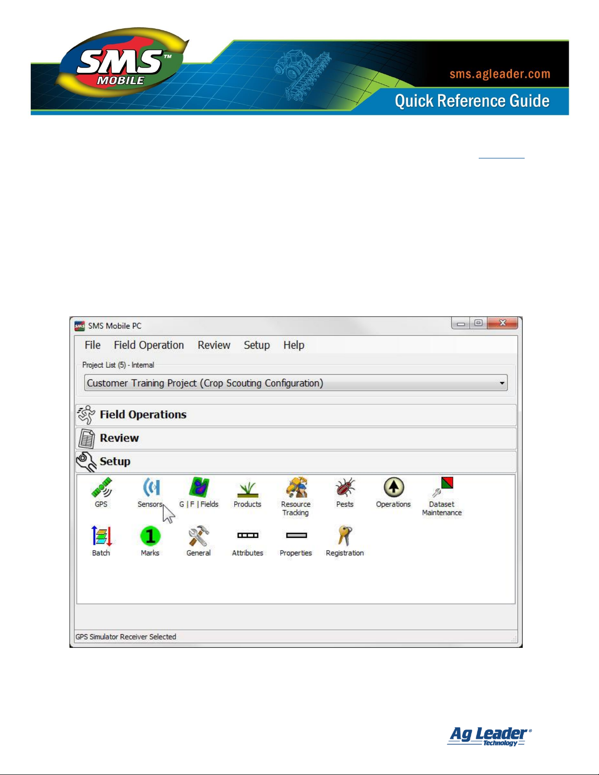
3. Tap the Setup menu and then the Sensors icon.
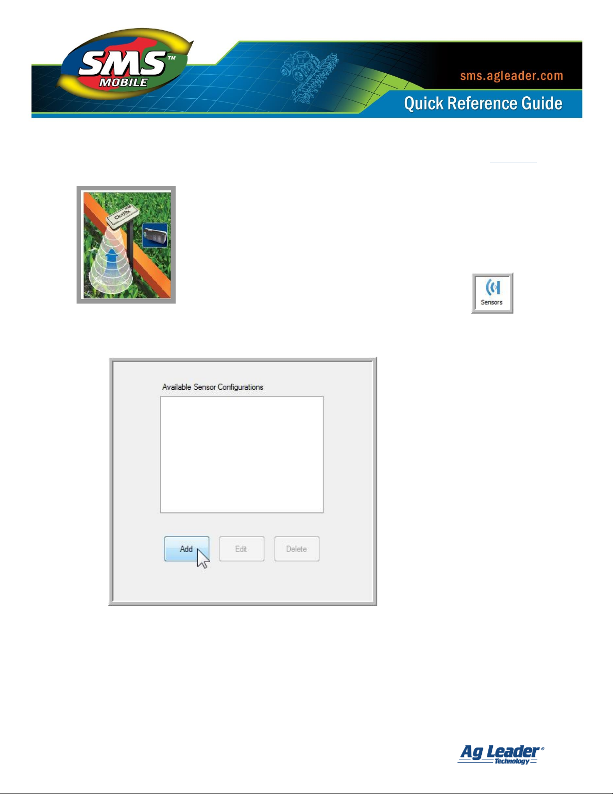
4. In the Available Sensor Configurations window tap Add.
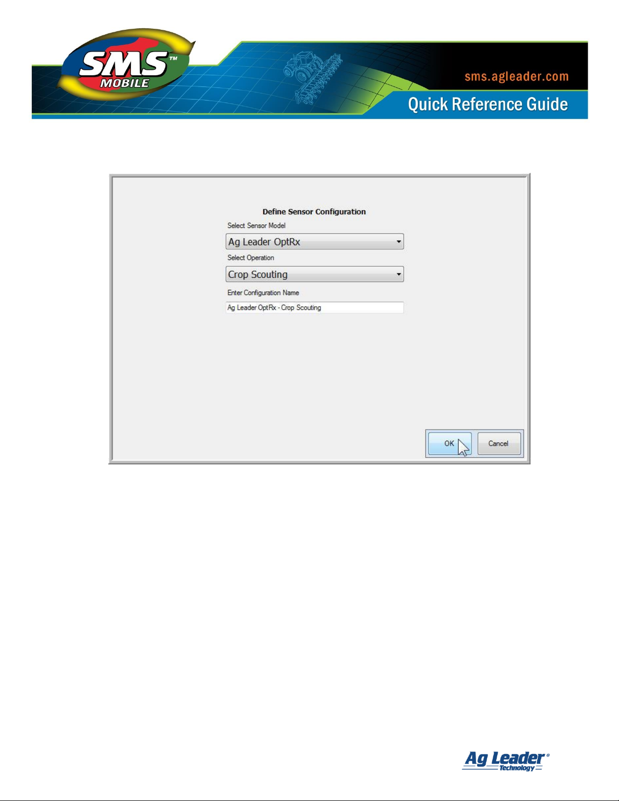
5. Select Ag Leader OptRx from the Sensor Model drop down menu.
6. Choose the Operation you wish to record data from the OptRx in.
7. Enter a Configuration Name so that you can recognize this sensor in the future when
displayed in the list of Available Sensor Configurations.
SMS Mobile S ensor Configuration and Log gi ng O pt ions
Revision 8/1/2013 © 2013 Ag Leader Technology, Inc All Rights Reserved
Page 5
4
8. Tap OK.
9. On the Sensor Port/Connection Settings window the settings to use with the OptRx
Sensor will be predefined for you:
a. Serial Port: COM1
b. Baud Rate: 38400
c. Data Bits: 8
d. Parity: None
e. Stop Bits: 1
10. Tap Test Sensor.
a. Tap OK after verifying the OptRx Sensor is turned on.
b. Once testing is complete you should receive a message indicating that
messages have been received from the sensor and that it is connected.
c. Tap OK.
SMS Mobile S ensor Configuration and Log gi ng O pt ions
Revision 8/1/2013 © 2013 Ag Leader Technology, Inc All Rights Reserved
Page 6

5
11. Select the Attributes you wish to log from the sensor by placing a check mark in the
box next to their name. Tap OK when finished.
12. The OptRx configuration will now be displayed in the list of available sensors and
can be used to record data in the operating mode that you designated.
SMS Mobile S ensor Configuration and Log gi ng O pt ions
Revision 8/1/2013 © 2013 Ag Leader Technology, Inc All Rights Reserved
Page 7

6
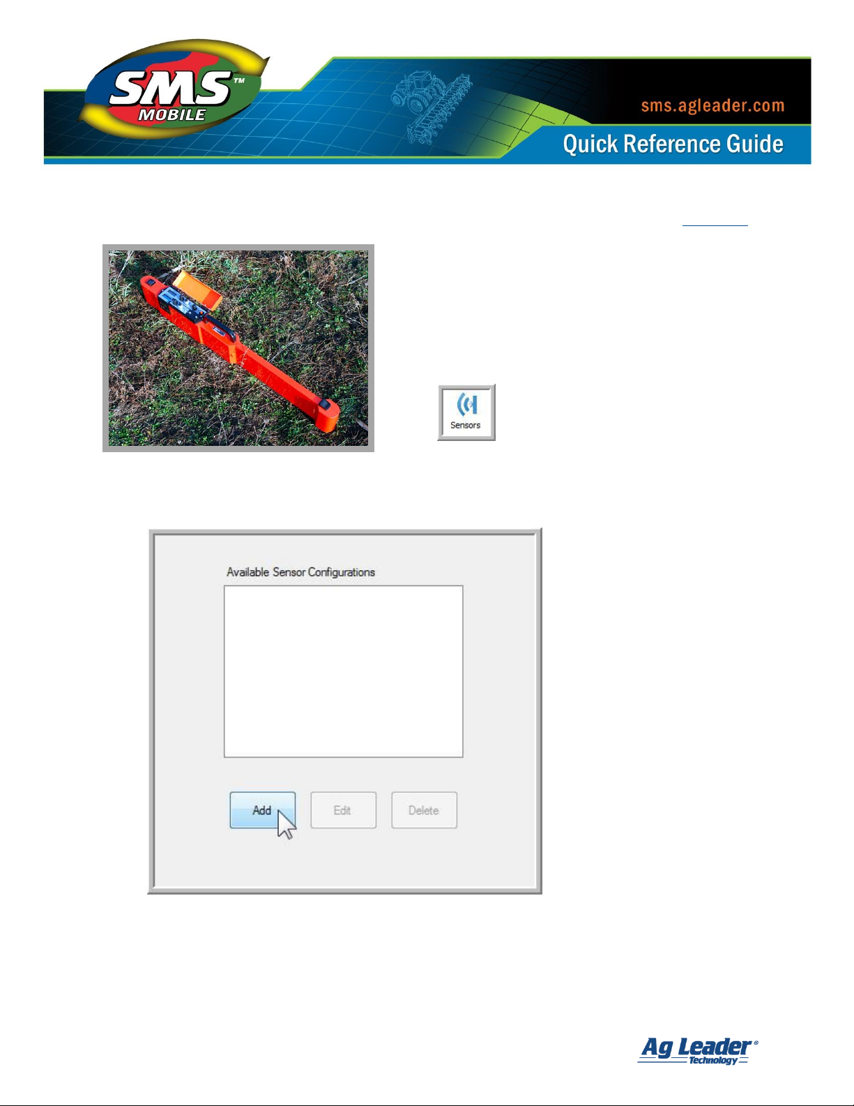
Connecting a Dualem 1s/2s/2/4 Sensor to SMS Mobile [Back to Top]
Photo courtesy of Dualem.com
1. Connect the Dualem Sensor to the Mesa, PC or handheld device with the serial cable
to the 9-pin serial port.
2. Open the SMS Mobile Software.
3. Tap the Setup menu and then the Sensors icon.
4. In the Available Sensor Configurations window tap Add.
SMS Mobile S ensor Configuration and Log gi ng O pt ions
Revision 8/1/2013 © 2013 Ag Leader Technology, Inc All Rights Reserved
Page 8
7
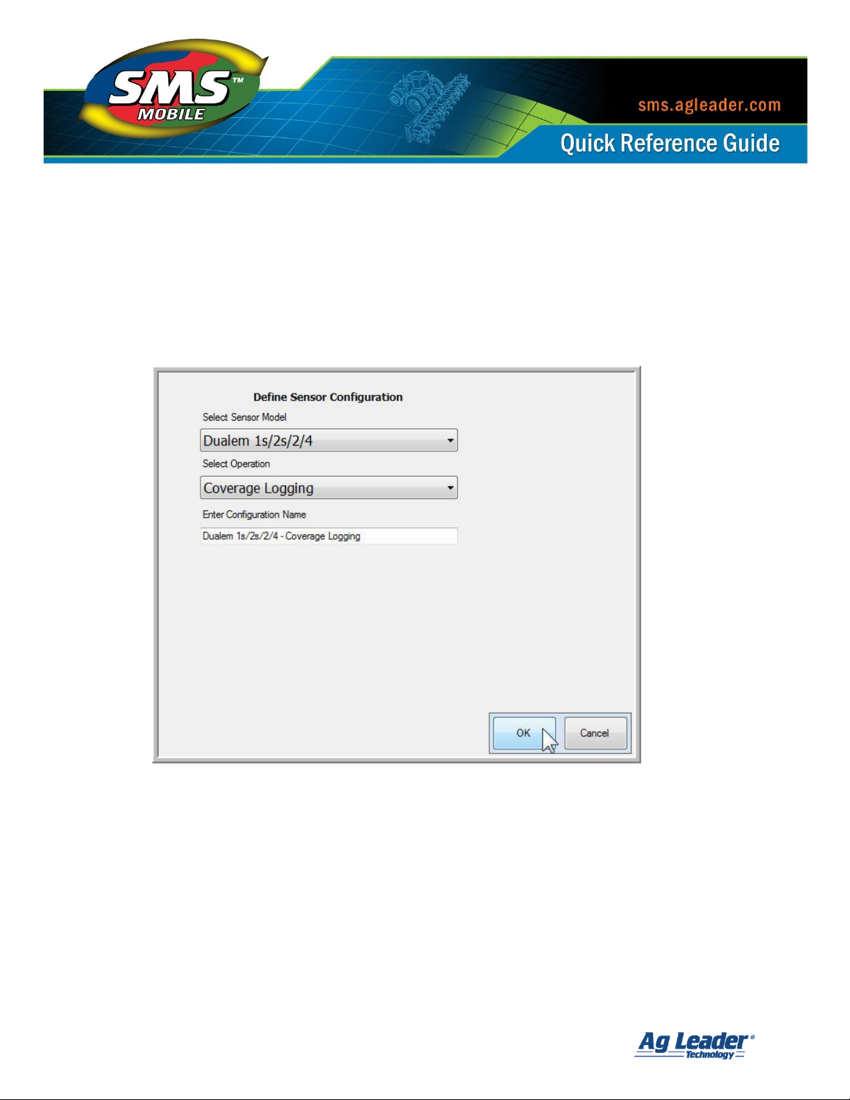
5. Select Dualem 1s/2s/2/4 from the Sensor Model drop down menu.
6. Choose the Operation you wish to record data from the Dualem Sensor in.
7. Enter a Configuration Name so that you can recognize this sensor in the future when
displayed in the list of Available Sensor Configurations.
8. Tap OK.
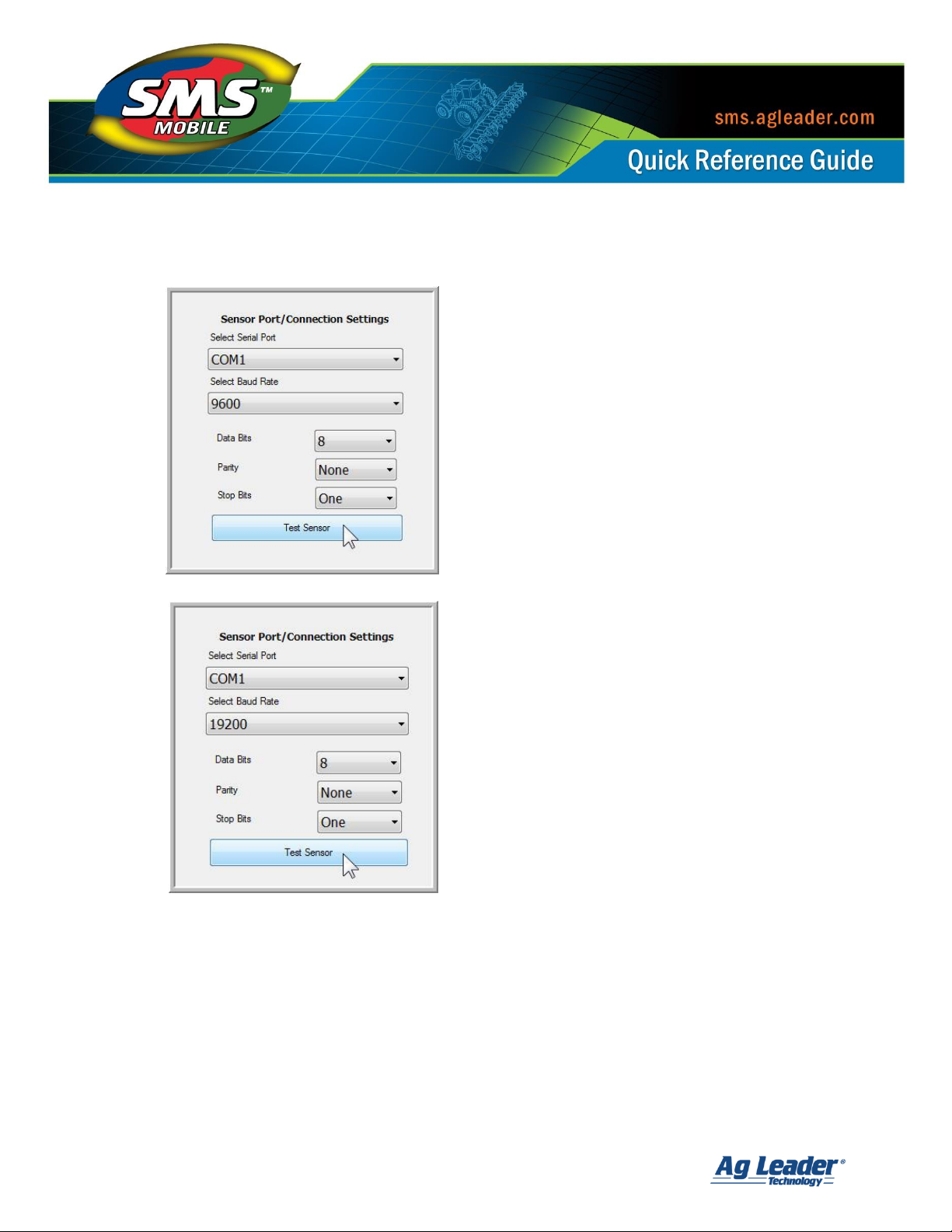
9. On the Sensor Port/Connection Settings window the settings to use with the Dualem
Sensor will be predefined for you:
a. Serial Port: COM1
b. Baud Rate: 9600
c. Data Bits: 8
d. Parity: None
e. Stop Bits: 1
SMS Mobile S ensor Configuration and Log gi ng O pt ions
Revision 8/1/2013 © 2013 Ag Leader Technology, Inc All Rights Reserved
Page 9

8
10. Tap Test Sensor.
a. Tap OK after turning on the Dualem Sensor. (The arrow on the end of the
sensor MUST be pointing up and all wires connected. Newer sensors will say
“DUALEM” instead of displaying the arrow. The text must be in the upright and
readable position).
b. Once testing is complete you should receive a message indicating that
messages have been received and that it is connected.
c. Tap OK.
11. Select the Attributes you wish to log from the sensor by placing a check mark in the
box next to their name. Tap OK when finished.
SMS Mobile S ensor Configuration and Log gi ng O pt ions
Revision 8/1/2013 © 2013 Ag Leader Technology, Inc All Rights Reserved
Page 10

9
12. The Dualem configuration will now be displayed in the list of available sensors and
can be used to record data in the operating mode that you designated.
SMS Mobile S ensor Configuration and Log gi ng O pt ions
Revision 8/1/2013 © 2013 Ag Leader Technology, Inc All Rights Reserved
Page 11
10
Connecting a Geonics Sensor to SMS Mobile [Back to Top]
1. Connect the Geonics Sensor to the Mesa,
PC or handheld device with the serial cable
to the 9-pin serial port.
2. Open the SMS Mobile Software.
3. Tap the Setup menu and then the
Sensors icon.
Photo courtesy of Geonics, Inc.
4. In the Available Sensor Configurations window tap Add.
SMS Mobile S ensor Configuration and Log gi ng O pt ions
Revision 8/1/2013 © 2013 Ag Leader Technology, Inc All Rights Reserved
Page 12

11
5. Select the Geonics Sensor that you will be using:
a. EM38
b. EM38-B
c. EM38-DD
d. EM38-MK2
6. Choose the Operation you wish to record data from the Geonics Sensor in.
7. Enter a Configuration Name so that you can recognize this sensor in the future when
displayed in the list of Available Sensor Configurations.
8. Tap OK.
SMS Mobile S ensor Configuration and Log gi ng O pt ions
Revision 8/1/2013 © 2013 Ag Leader Technology, Inc All Rights Reserved
Page 13
12
9. On the Sensor Port/Connection Settings window the settings to use with the Geonics
Sensor will be predefined for you:
a. Geonics EM38/38-B/38-DD:
i. Serial Port: COM1
ii. Baud Rate: 9600
iii. Data Bits: 8
iv. Parity: None
v. Stop Bits: 1
b. Geonics EM38-MK2:
i. Serial Port: COM1
ii. Baud Rate: 19200
iii. Data Bits: 8
iv. Parity: None
v. Stop Bits: 1
10. Tap Test Sensor.
a. Tap OK after turning on the Geonics Sensor. The EM38 will need to be in Q/P
Mode and not I/P Mode.
b. Once testing is complete you should receive a message indicating that
messages have been received and that it is connected.
c. Tap OK.
SMS Mobile S ensor Configuration and Log gi ng O pt ions
Revision 8/1/2013 © 2013 Ag Leader Technology, Inc All Rights Reserved
Page 14

13
11. Select the Attributes you wish to log from the sensor by placing a check mark in the
box next to their name. Tap OK when finished.
12. The Geonics configuration will now be displayed in the list of available sensors and
can be used to record data in the operating mode that you designated.
SMS Mobile S ensor Configuration and Log gi ng O pt ions
Revision 8/1/2013 © 2013 Ag Leader Technology, Inc All Rights Reserved
Page 15

14
Connecting a GreenSeeker RT100/500/505 Sensor
to SMS Mobile [Back to Top]
1. Connect the GreenSeeker Sensor to the Mesa, PC or handheld
device with the serial cable (supplied with the GreenSeeker
unit) to the 9-pin serial port. If using the 505 model you will
need to connect the GreenSeeker Sensor to a null modem
cable (Ag Leader Part Number: 200819) with a gender adapter
(available at any electronics store) between the null modem
and PC cable.
Photo courtesy of GreenSeeker
2. Open the SMS Mobile Software.
3. Tap the Setup menu and then the Sensors icon.
4. In the Available Sensor Configurations window tap Add.
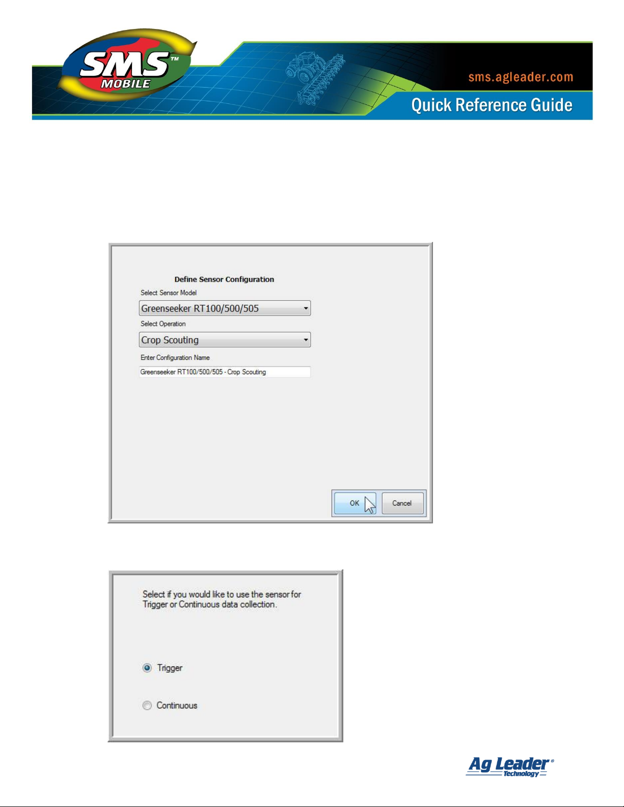
5. Select the GreenSeeker RT100/500/505 from the Sensor Model drop down menu.
SMS Mobile S ensor Configuration and Log gi ng O pt ions
Revision 8/1/2013 © 2013 Ag Leader Technology, Inc All Rights Reserved
Page 16
15
6. Choose the Operation you wish to record data from the GreenSeeker Sensor in.
7. Enter a Configuration Name so that you can recognize this sensor in the future when
displayed in the list of Available Sensor Configurations.
8. Tap OK.
9. Select if you will be using the sensor for Trigger or Continuous data collection. Tap OK.
SMS Mobile S ensor Configuration and Log gi ng O pt ions
Revision 8/1/2013 © 2013 Ag Leader Technology, Inc All Rights Reserved
Page 17

16
10. On the Sensor Port/Connection Settings window the settings to use with the
GreenSeeker Sensor will be predefined for you:
a. Serial Port: COM1
b. Baud Rate: 38400
c. Data Bits: 8
d. Parity: None
e. Stop Bits: 1
11. Tap Test Sensor.
a. Tap OK after turning on the GreenSeeker Sensor. Once testing is complete
you should receive a message indicating that messages have been received
and that it is connected.
b. Tap OK.
SMS Mobile S ensor Configuration and Log gi ng O pt ions
Revision 8/1/2013 © 2013 Ag Leader Technology, Inc All Rights Reserved
Page 18

17
12. Select the Attributes you wish to log from the sensor by placing a check mark in the
box next to their name. Tap OK when finished.
13. The GreenSeeker configuration will now be displayed in the list of available sensors
and can be used to record data in the operating mode that you designated.
SMS Mobile S ensor Configuration and Log gi ng O pt ions
Revision 8/1/2013 © 2013 Ag Leader Technology, Inc All Rights Reserved
Page 19

18
Connecting a Holland Scientific 430 Sensor to SMS Mobile
[Back to Top]
1. Connect the Holland Scientific Sensor to the 9-pin end
of the cable to the 9-pin port on the Mesa, PC or
handheld device.
2. Open the SMS Mobile Software and turn on the
Holland Scientific Sensor.
Photo courtesy of Holland Scientific
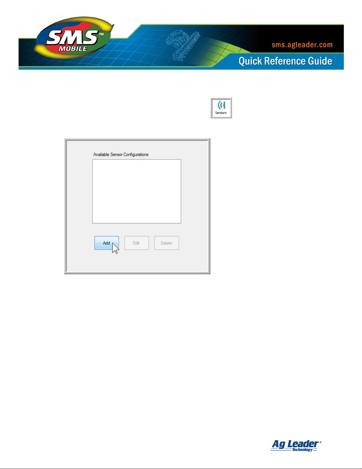
3. Tap the Setup menu and then the Sensors icon.
4. In the Available Sensor Configurations window tap Add.
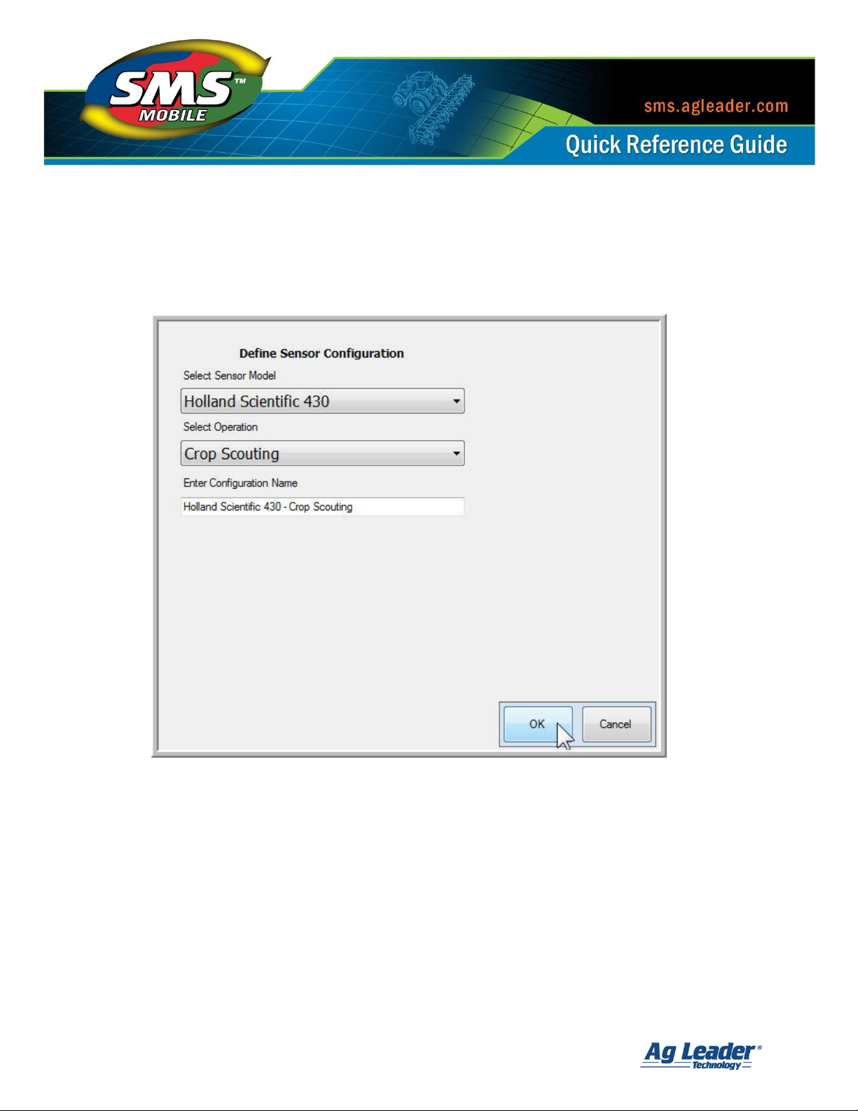
5. Select Holland Scientific 430 from the Sensor Model drop down menu.
6. Choose the Operation you wish to record data from the 430 in.
SMS Mobile S ensor Configuration and Log gi ng O pt ions
Revision 8/1/2013 © 2013 Ag Leader Technology, Inc All Rights Reserved
Page 20
19
7. Enter a Configuration Name so that you can recognize this sensor in the future when
displayed in the list of Available Sensor Configurations.
8. Tap OK.
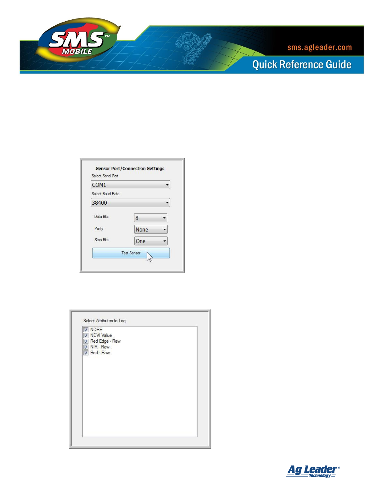
9. On the Sensor Port/Connection Settings window the settings to use with the Holland
Scientific Sensor will be predefined for you:
a. Serial Port: COM1
b. Baud Rate: 38400
c. Data Bits: 8
d. Parity: None
e. Stop Bits: 1
SMS Mobile S ensor Configuration and Log gi ng O pt ions
Revision 8/1/2013 © 2013 Ag Leader Technology, Inc All Rights Reserved
Page 21
20
10. Tap Test Sensor.
a. Tap OK after verifying the 430 Sensor is turned on.
b. Once testing is complete you should receive a message indicating that
messages have been received from the sensor and that it is connected.
c. Tap OK.
11. Select the Attributes you wish to log from the sensor by placing a check mark in the
box next to their name. Tap OK when finished.
SMS Mobile S ensor Configuration and Log gi ng O pt ions
Revision 8/1/2013 © 2013 Ag Leader Technology, Inc All Rights Reserved
Page 22

21
12. The Holland Scientific configuration will now be displayed in the list of available
sensors and can be used to record data in the operating mode that you designated.
SMS Mobile S ensor Configuration and Log gi ng O pt ions
Revision 8/1/2013 © 2013 Ag Leader Technology, Inc All Rights Reserved
Page 23

22
Connecting a Minolta 502 Spad Meter to SMS Mobile [Back to Top]
1. Turn the SPAD meter on. The word ‘CAL” should be shown
on the screen. Connect the SPAD Meter to the 9-pin port on
the Mesa, PC or handheld device.
2. Open the SMS Mobile Software.
3. Tap the Setup menu and then the Sensors icon.
Photo courtesy of Spectrum
Technologies
4. In the Available Sensor Configurations window tap Add.
5. Select Minolta 502 SPAD Meter from the Sensor Model drop down menu.
6. Choose the Operation you wish to record data from the SPAD Meter in.
7. Enter a Configuration Name so that you can recognize this sensor in the future when
displayed in the list of Available Sensor Configurations.
SMS Mobile S ensor Configuration and Log gi ng O pt ions
Revision 8/1/2013 © 2013 Ag Leader Technology, Inc All Rights Reserved
Page 24

23
8. Tap OK.
9. On the Sensor Port/Connection Settings window the settings to use with the SPAD
Meter will be predefined for you:
a. Serial Port: COM1
b. Baud Rate: 4800
c. Data Bits: 7
d. Parity: None
e. Stop Bits: 1
SMS Mobile S ensor Configuration and Log gi ng O pt ions
Revision 8/1/2013 © 2013 Ag Leader Technology, Inc All Rights Reserved
Page 25

24
10. Tap Test Sensor (you will need a sample leaf or test strip).
a. Tap OK after verifying the SPAD Meter is turned on.
b. Once testing is complete you should receive a message indicating that
messages have been received from the sensor and that it is connected.
c. Tap OK.
11. Select the Attributes you wish to log from the sensor by placing a check mark in the
box next to their name. Tap OK when finished.
SMS Mobile S ensor Configuration and Log gi ng O pt ions
Revision 8/1/2013 © 2013 Ag Leader Technology, Inc All Rights Reserved
Page 26

25
12. The Minolta SPAD Meter configuration will now be displayed in the list of available
sensors and can be used to record data in the operating mode that you designated.
SMS Mobile S ensor Configuration and Log gi ng O pt ions
Revision 8/1/2013 © 2013 Ag Leader Technology, Inc All Rights Reserved
Page 27

26
Connecting a VERIS Surveyor/Instrument to SMS Mobile [Back to Top]
1. Connect the Veris Monitor via serial port connection to the Mesa, PC
or handheld device.
2. Open the SMS Mobile Software.
3. Tap the Setup menu and then the Sensors icon.
Photo courtesy of
Veristech.com
4. In the Available Sensor Configurations window tap Add.
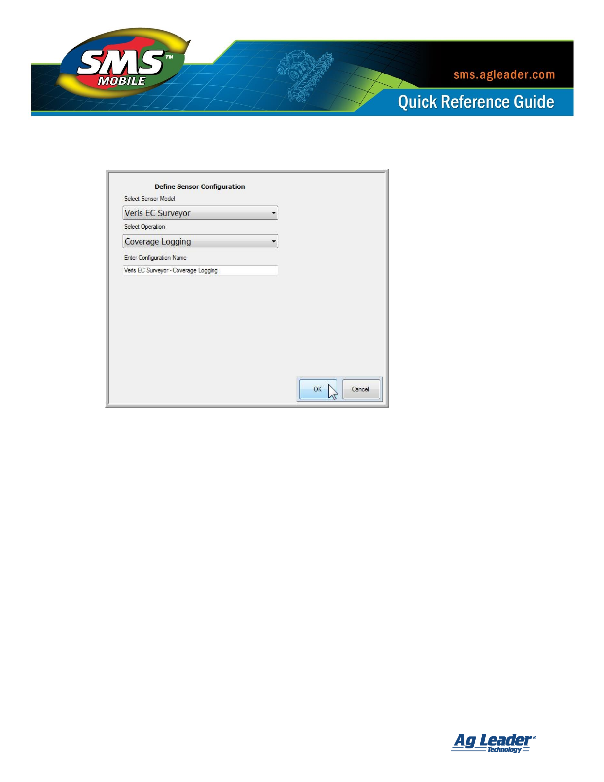
5. Select the Veris EC Surveyor/Instrument from the Sensor Model drop down menu.
6. Choose the Operation you wish to record data from the Veris Monitor in.
7. Enter a Configuration Name so that you can recognize this sensor in the future when
displayed in the list of Available Sensor Configurations.
SMS Mobile S ensor Configuration and Log gi ng O pt ions
Revision 8/1/2013 © 2013 Ag Leader Technology, Inc All Rights Reserved
Page 28
27
8. Tap OK.
9. On the Sensor Port/Connection Settings window the settings to use with the Veris
Sensor will be predefined for you:
a. Serial Port: COM1
b. Baud Rate: 9600
c. Data Bits: 8
d. Parity: None
e. Stop Bits: 1
SMS Mobile S ensor Configuration and Log gi ng O pt ions
Revision 8/1/2013 © 2013 Ag Leader Technology, Inc All Rights Reserved
Page 29

28
10. Tap Test Sensor.
a. Tap OK after verifying the Veris Monitor is turned on. In order to test the Veris
Display, you will need to be traveling more than .08 miles per hour and have a
GPS fix.
b. Once testing is complete you should receive a message indicating that
messages have been received from the sensor and that it is connected.
c. Tap OK.
11. Select the Attributes you wish to log from the sensor by placing a check mark in the
box next to their name. Tap OK when finished.
SMS Mobile S ensor Configuration and Log gi ng O pt ions
Revision 8/1/2013 © 2013 Ag Leader Technology, Inc All Rights Reserved
Page 30

29
12. The Veris configuration will now be displayed in the list of available sensors and can
be used to record data in the operating mode that you designated.
SMS Mobile S ensor Configuration and Log gi ng O pt ions
Revision 8/1/2013 © 2013 Ag Leader Technology, Inc All Rights Reserved
Page 31

30
Defining a Custom Sensor [Back to Top]
To define a custom sensor you must specify how the information provided from the sensor is
organized and how SMS Mobile should interpret that data. The following parameters must
be set when defining a custom sensor configuration:
Define Sensor Header to Parse – Defines what text strings from the sensor contains the
data you wish to log. For example, in an ASCII text string formatted as: $, 123.5,
South, XYZ if you wanted to record the 123.5, South and XYZ, then you must define
the $ as the header. After defining the Header then SMS Mobile will know that all
data following this Header will be recorded.
String Delimiter – This setting defines the formatting of the ASCII text string to be
parsed, i.e. how each attribute in the string is separated from one another. Options
are commas, spaces and tabs.
String Terminator – This setting defines how each ASCII text string outputted by the
sensor ends and thus defines the start of the next string.
Logging Type – This setting defines how often the sensor will output data.
Trigger Type – should be used when the sensor outputs a single reading on
demand.
Continuous Type – should be used when the sensor outputs readings
automatically and constantly without any user control. When Continuous is
selected and the sensor is used in any operating mode except for Coverage
Logging then a Sensor icon will appear on the map that will allow you to take a
reading for the currently selected object in the layer.
SMS Mobile S ensor Configuration and Log gi ng O pt ions
Revision 8/1/2013 © 2013 Ag Leader Technology, Inc All Rights Reserved
Page 32
31
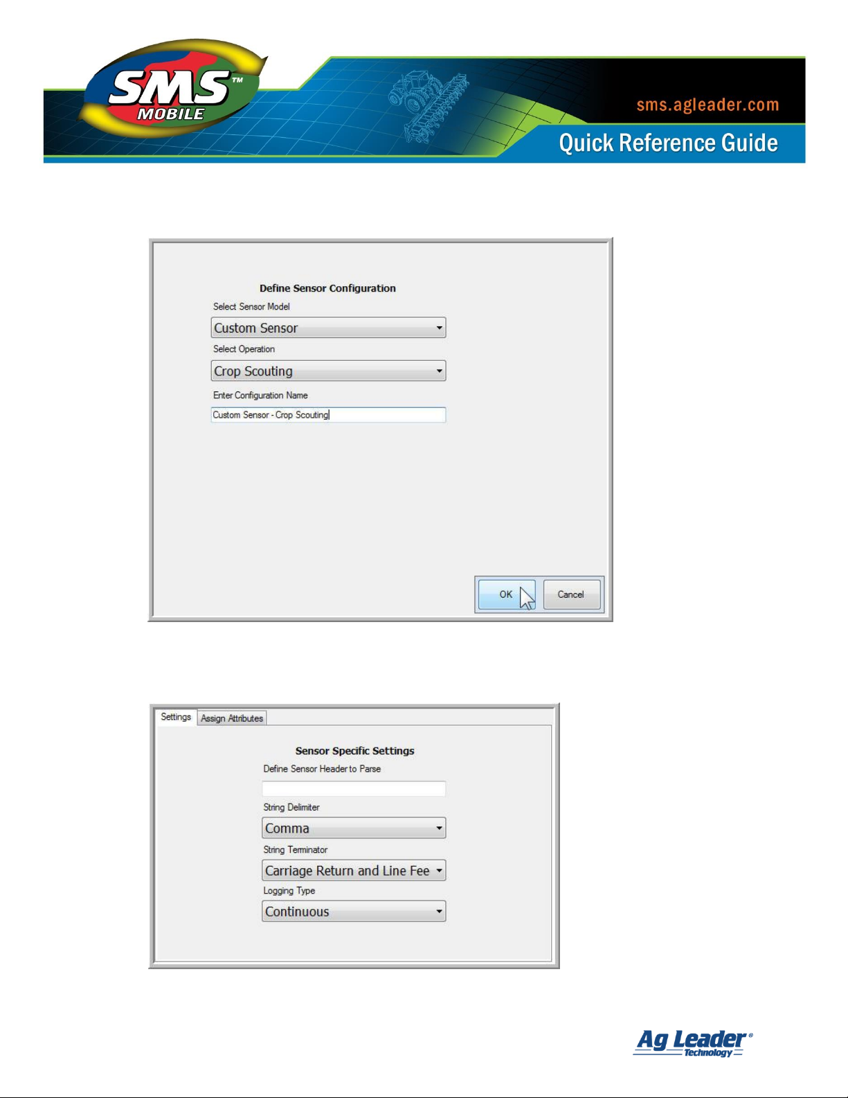
To create a custom sensor in SMS Mobile follow the steps below:
1. Tap the Setup menu and then the Sensors icon.
2. In the Available Sensor Configurations window tap Add.
3. Choose Custom Sensor under the Select Sensor Model drop down menu.
4. Choose the Operation you would like to use this sensor in.
5. Enter a Configuration Name so that you can recognize this sensor in the future when
displayed in the list of Available Sensor Configurations.
SMS Mobile S ensor Configuration and Log gi ng O pt ions
Revision 8/1/2013 © 2013 Ag Leader Technology, Inc All Rights Reserved
Page 33
32
6. Tap OK.
7. On the Sensor Specific Settings input the Define Sensor Header to Parse and select
the string delimiter and terminator and the logging type.
SMS Mobile S ensor Configuration and Log gi ng O pt ions
Revision 8/1/2013 © 2013 Ag Leader Technology, Inc All Rights Reserved
Page 34

33
8. Tap the Assign Attributes tab and assign any attribute that you wish to log with this
sensor by tapping on the column and then using the Assign Column button.
a. Choose the Attribute Group, Attribute Name, Units, and how to handle data if
Multiple Samples are sent from the sensor to SMS Mobile.
9. Tap OK.
10. Select the Port and Connection Settings for the sensor.
a. Input the serial port, baud rate, data bits, parity, and stop bits.
SMS Mobile S ensor Configuration and Log gi ng O pt ions
Revision 8/1/2013 © 2013 Ag Leader Technology, Inc All Rights Reserved
Page 35

34
11. Tap the Test Sensor button. When prompted to turn on the sensor, turn it on and
then tap OK.
a. If the sensor is configured correctly you will receive a message indicating that
the sensor message was received and that it is connected.
b. If the sensor is not configured correctly you will receive a message indicating
that the sensor was not found, please check sensor connections and settings.
12. After testing the sensor tap OK.
13. Select the Attributes you wish to log from the sensor by placing a check mark in the
box next to their name. Tap OK when finished.
14. The sensor will now appear in the list of Available Sensor Configurations and can be
used to record data within the designated operating mode.
SMS Mobile S ensor Configuration and Log gi ng O pt ions
Revision 8/1/2013 © 2013 Ag Leader Technology, Inc All Rights Reserved
Page 36

35
Logging Data and Configuring Tooltips [Back to Top]
To begin logging data from the sensors you have configured follow the steps below:
1. Enter the Operating Mode of SMS Mobile that you designated for your specific sensor.
2. Continue thru the operations setup window until the Select Attributes/Sensors
window opens.
SMS Mobile S ensor Configuration and Log gi ng O pt ions
Revision 8/1/2013 © 2013 Ag Leader Technology, Inc All Rights Reserved
Page 37

36
3. Tap on the Sensors tab and select the desired sensor. Tap OK.
4. When you begin logging data, if the sensor was setup as Continuous Logging your
values will automatically be recorded. If the sensor was setup as Trigger Logging each
time you take a reading the value will be added to the logged data in SMS Mobile.
To display tooltips while logging data with a sensor so that the values you are
recording are displayed in the lower left hand corner of the SMS Mobile Software
follow the steps below:
1. In the operation window go to the Map menu and select Tooltips.
SMS Mobile S ensor Configuration and Log gi ng O pt ions
Revision 8/1/2013 © 2013 Ag Leader Technology, Inc All Rights Reserved
Page 38

37
2. Select the Layer that you are working with that contains the data you would like to
see the tooltips from.
3. Select the appropriate Attribute to display as a tooltip, i.e. EC Shallow, EC Deep,
Chlorophyll Index, or any custom defined attribute.
a. You can turn on two tooltips while logging data with SMS Mobile, allowing you
to view two attributes at once.
SMS Mobile S ensor Configuration and Log gi ng O pt ions
Revision 8/1/2013 © 2013 Ag Leader Technology, Inc All Rights Reserved
 Loading...