

Page 1

Precision Farming System
Operators Manual
Page 2

Page 3

PFadvantage
Ag Leader Technology
Welcome
System Upgrades
Product
Registration
Welcome to the Ag Leader Technology family. Ag Leader Technology is
dedicated to the development of advanced, yet practical and cost-effective
tools for grain production. Above all, however, we are dedicated to meeting
your needs for support of existing products and development of product
improvements.
We want to hear from you! Feel free to call any time to discuss:
• Operational problems with your system
• Features you don’t like about your system
• Features you would like added to your system
We will do our best to ensure that you are happy with your current system
and that it is upgraded in the future to better meet your needs.
Ag Leader Technology will periodically provide operating program
upgrades that will improve the performance of your PFadvantage.
PFadvantage operating program upgrades will be available as Internet
downloadable files from the Ag Leader web site.
Internet http://www.agleader.com
If you do not have access to the Ag Leader web site contact your Ag
Leader dealer to request the latest operating program upgrades or
contact our Technical Support Group (515) 232-5363 ext. 1
Your timely product registration will allow you to receive important
product bulletins and information regarding product training in your area.
Register On-Line at www.agleader.com, or return the registration form at
the front of this manual via mail or fax to the address listed below.
General
Ag Leader Technology
2202 South Riverside Drive
P.O. Box 2348
Ames, Iowa 50010
515-232-3595 - fax
September 2003
1-1
Page 4

General
Limited Warranty
Service
Copyright Notice
Proprietary
Technology Notice
PFadvantage
Ag Leader Technology
Ag Leader Technology will repair or replace at no charge any component of the
PFadvantage system that fails during normal service on the equipment model that the
system was intended for use within two years from the warranty start date.
The warranty start date will initially be set to the date on which your product is
shipped from Ag Leader Technology.
If you return the registration/warranty card included with this manual within 30
days of purchasing this product from your dealer, the warranty start date will be
changed to the date that you purchased this product from your dealer. Ag Leader
Technology reserves the right to request proof of the date stated on your
registration/warranty card.
Warranty is not provided for damage resulting from abuse, neglect, accidents, vandalism,
acts of nature, or any other causes that are outside the normal, intended use of the
PFadvantage system.
Ag Leader Technology shall not be liable for indirect, incidental, or consequential
damages to the dealer, end user, or third parties arising from the sale, installation, or use of
the PFadvantage system.
If you have a problem with your system, call your Ag Leader Technology dealer
or call us directly at the phone number below. If we determine you have a
hardware failure, we will ship replacement hardware immediately. Our mailing
address and phone numbers are:
Ag Leader Technology
2202 South Riverside Drive
P.O. Box 2348
Ames, IA 50010
Phone: 515-232-5363
Fax: 515-232-3595
Note: Return failed hardware to us by UPS (preferred) or US mail.
Ag Leader Technology has copyrighted (©2002) the contents of this manual and
the operating program for the PFadvantage system. No reproductions of this
material may be made without first obtaining the consent of Ag Leader
Technology.
The PFadvantage system has patents on its design and operational features.
Copying features of this system relating to measurement and calculation of grain
flow and weight, or organization of field and load data may result in patent
infringement.
1-2
September 2003
Page 5

PFadvantage
Ag Leader Technology
General
Description
Fields and Loads
Keypad
The PFadvantage is a universal monitor/controller for crop production. It
can be transferred from a combine to a tractor or other vehicles easily. In
the combine it functions as a yield monitor and accurately measures and
records acres, moisture, grain weight, bushels, and yield on-the-go. In the
tractor or sprayer it connects to a sprayer or planter controller and monitors
and controls the application rate. The PFadvantage also can record data for
field boundaries, tile lines or where a hybrid is planted.
The PFadvantage has its own internal memory for recording field and load
data. GPS data, however, is not recorded in the internal memory, but
must be logged to a memory card.
The PFadvantage must be setup and calibrated to record accurate
information.
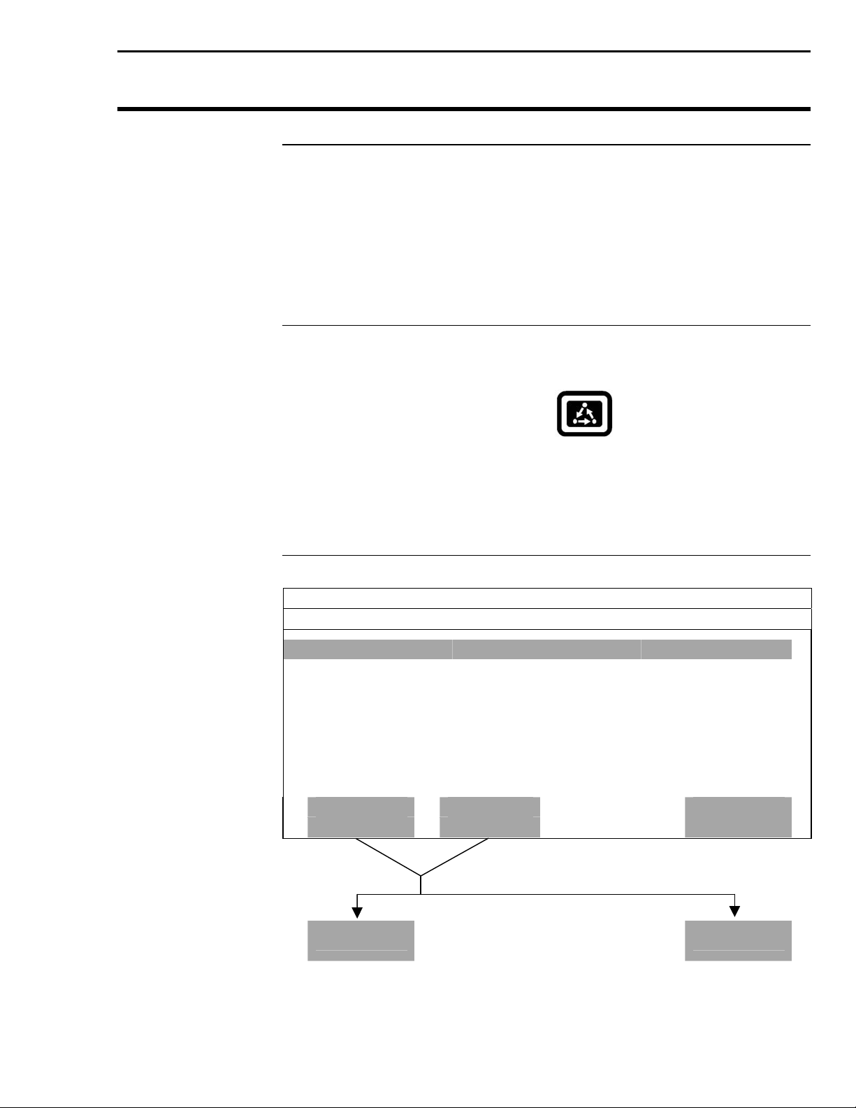
NOTE: The Grass Seed version of the PFadvantage is setup and
calibrated using the same procedures as for grain harvest. Where
there are differences between the harvest of grain verses grass seed
they will be noted.
All the information recorded by the PFadvantage must be recorded in a
field and load. The operator must manually select or change the field and
load on the PFadvantage during field operation. A load is used to
subdivide a field into smaller sections. The monitor load is not associated
with the combine tank, wagon, or truck load. It is recommended to use
different loads for different hybrids or varieties or field conditions.
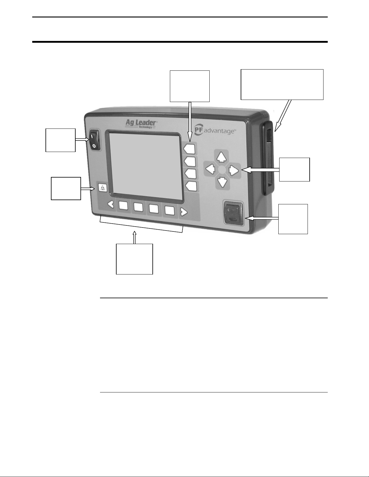
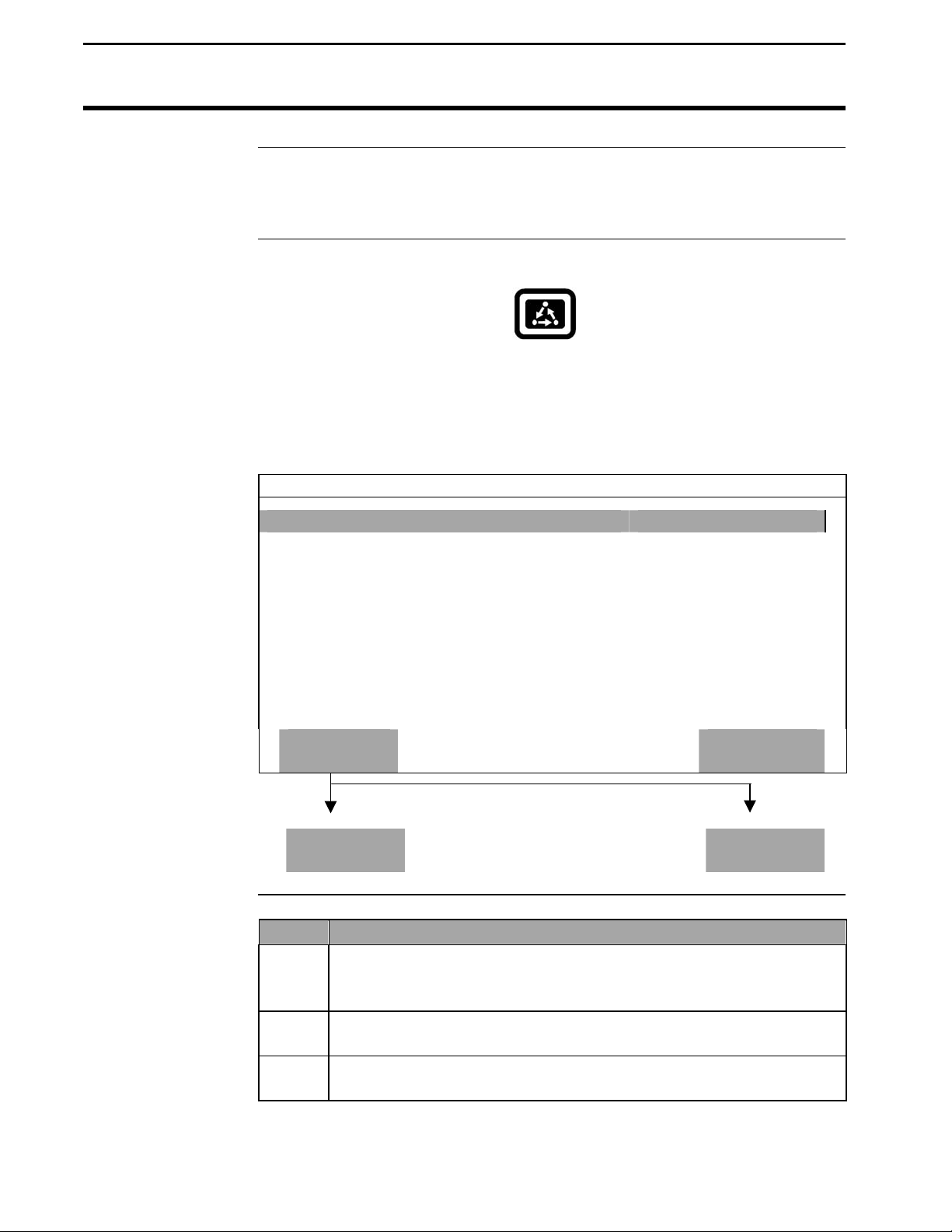
The monitor has “soft” keys which do not have labels on the keys to
identify the function of the key. The labels for the keys will appear on the
display screen next to the key. However, there are four major groups of the
keys: arrow keys, display selection keys, menu key, menu selection keys.
General
September 2003
1-3
Page 6
General
Power
Switch
Menu
Key
Arrow Keys
PFadvantage
Ag Leader Technology
Display
Selection
Keys
Menu
Selection
Keys
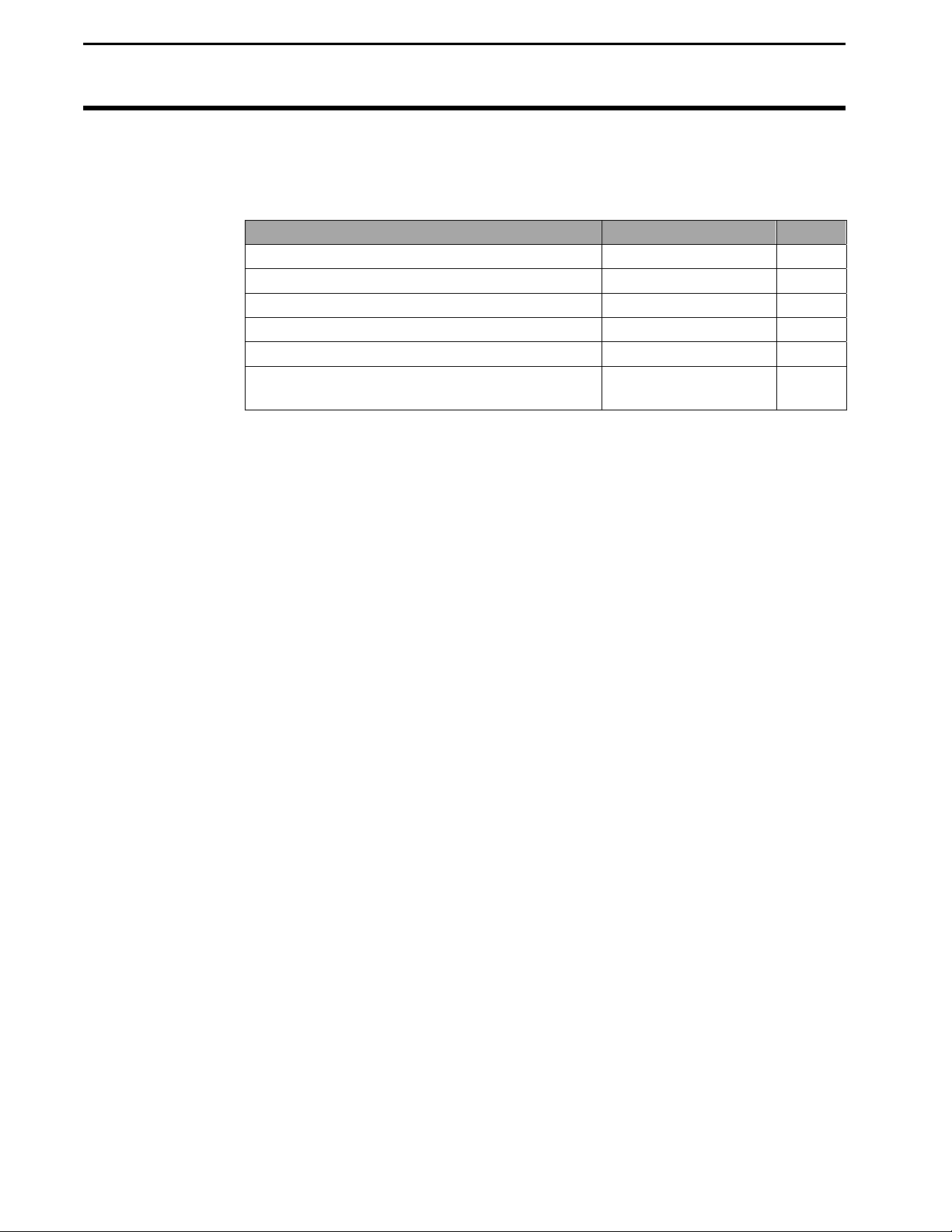
Figure 1: Front panel of the PFadvantage
The UP, DOWN, LEFT and RIGHT ARROW keys on the right side of the
keypad are used to select and change a setting. The bottom LEFT and
RIGHT ARROW keys are only used to view more menu or display items.
They are never used to select or change a setting.
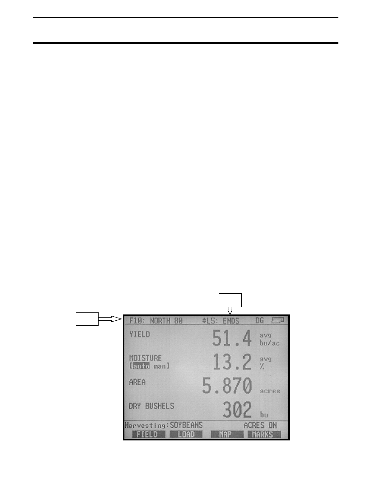
On the main operating screen, you will see an up and down arrow symbol
that will either be beside the field or load or to the right of one of the
display lines. This symbol indicates what item the UP or DOWN ARROW
keys will change if pressed.
Memory Card Slot
(On side of
PFadvantage)
Arrow
Keys
Area
Count
Switch
1-4
September 2003
Page 7
PFadvantage
p
Ag Leader Technology
Display and
Display Selection
Keys
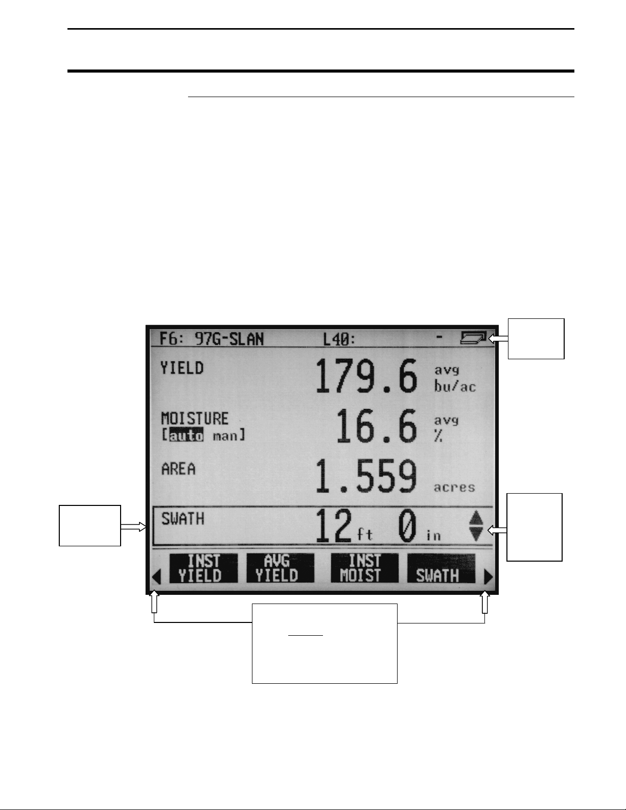
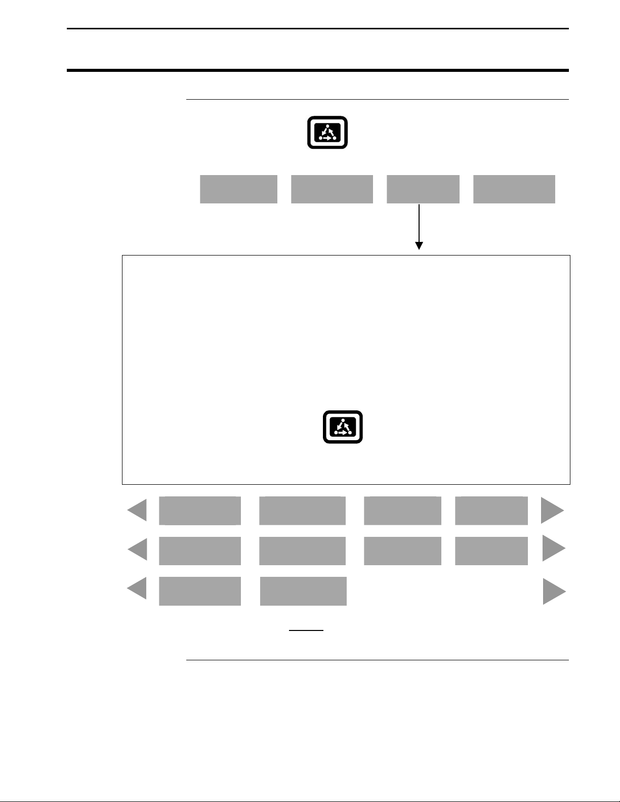
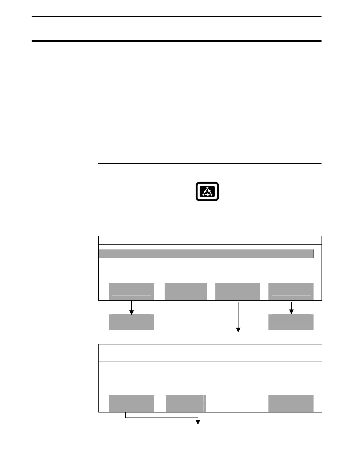
The PFadvantage has four display lines for viewing items on the main
operating screen. You can choose which items you see on the display and
the position that the items appear on the display.
To change a display item on a display line you must select the line. The four
display selection keys to the right of the display each select a display line.
A rectangular box surrounds the display line to show that it is selected.
When the display line is selected the four menu items on the bottom change
and show items you can select for display. Press a key below one of the
four display items to put a different display item in place of the selected
display item. There are more than four display items to choose for viewing.
Press the bottom LEFT or RIGHT ARROW keys to scroll to the right or left
and view other display items on the bottom.
General
Card
Symbol
Selection
Box
When arrows present,
ress bottom arrow keys
to display additional
menu or display items
Figure 2: Main operating screen
NOTE: Grass seed is measured in pounds per acre.
September 2003
Up and
Down
Arrow
Symbol
1-5
Page 8
General
Menu Key
PFadvantage
Ag Leader Technology
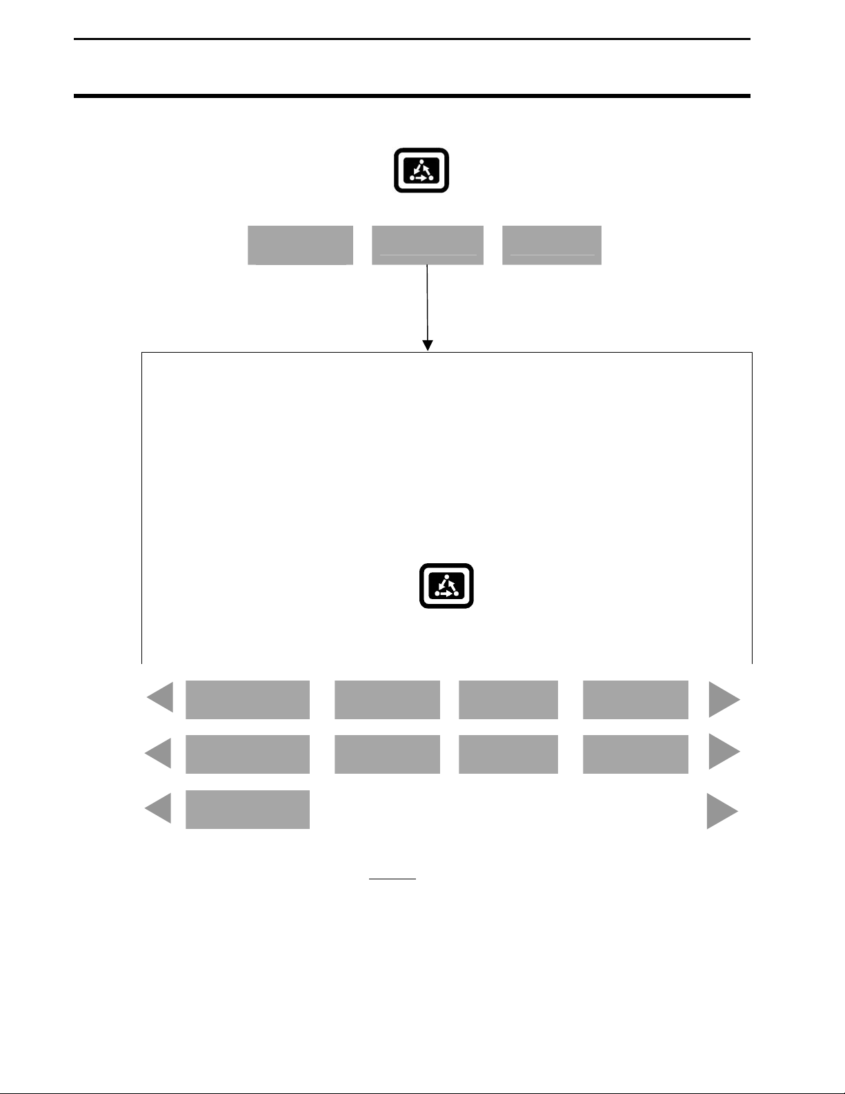
When some display items (like swath) are selected, an up and down arrow
symbol will appear on the right of the display line. This indicates you can
change the setting of the item with the UP or DOWN ARROW keys. After
you have made the change you must press the key to the right of the display
line to deselect the line.
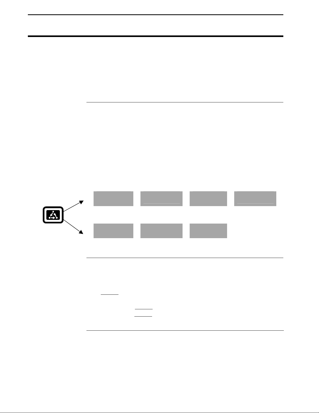
The MENU key switches the menus on the bottom of the display. There are
two main menus that you can view by pressing the MENU key. They are
shown below.
It is recommended to display the FIELD, LOAD, MAP, and OPTIONS
menu during normal operation of the monitor, unless you are marking and
therefore need to display marks on the bottom.
Main Menus:
FIELD
LOAD
SHOW
MAP
OPTIONS
CAL
Menu Selection
Keys
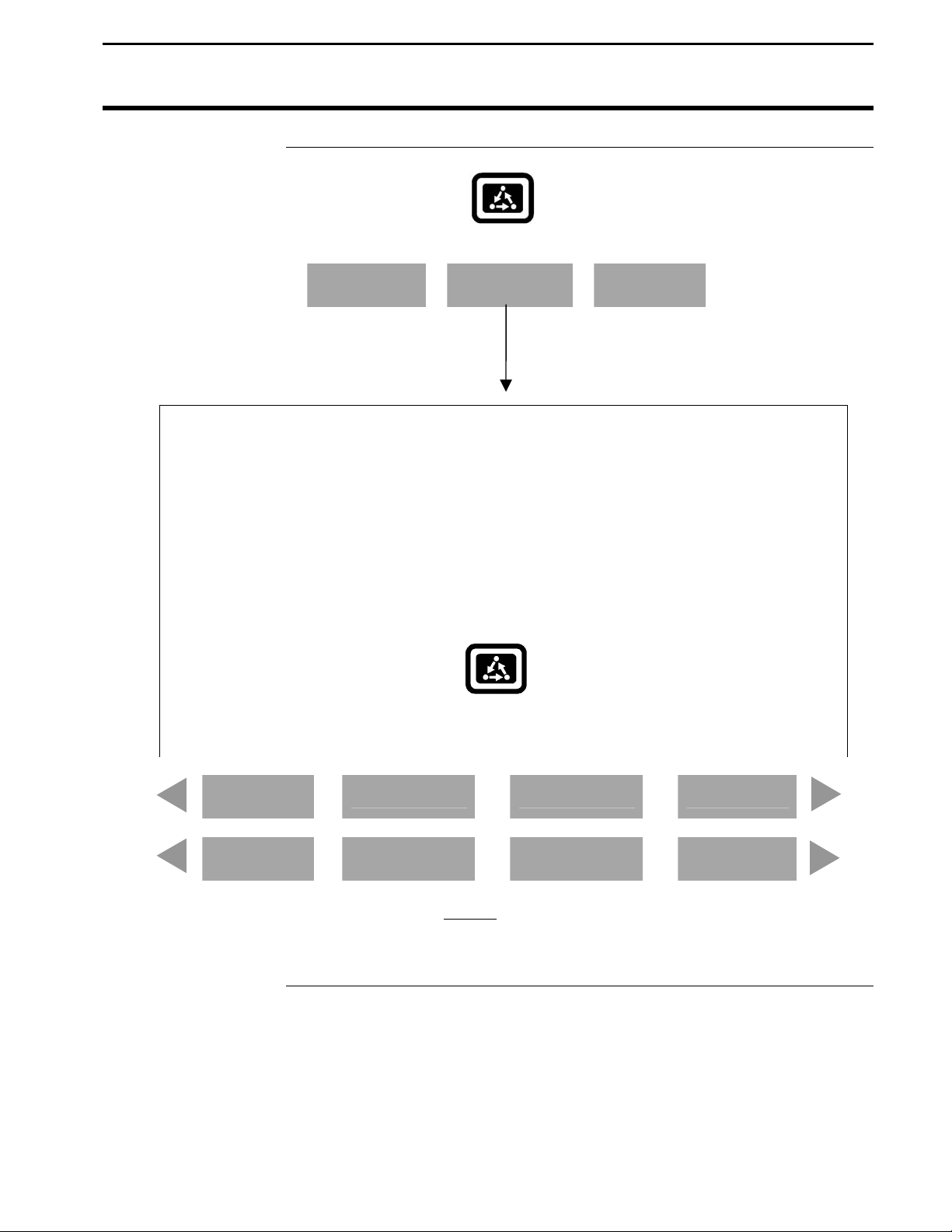
The name above the four menu selection keys on the bottom of the display
will change depending on what you are doing on the monitor.
The bottom
RIGHT and LEFT ARROW keys are used to view additional
menu or display items. If you see a right and left arrow symbol on the
display above the bottom RIGHT and LEFT ARROW keys, this indicates
you can press the bottom RIGHT and LEFT ARROW keys to view more
menu or display items. Refer to Figure 2.
SETUP
DIAG
1-6
September 2003
Page 9
PFadvantage
Ag Leader Technology
General
Area Count Switch
Connectors
The area count switch manually turns on and off area counting. When the
switch is in the up position area is counting. When the switch is in the
down position, area is not counting. The monitor will display either
“AREA ON” or “AREA OFF” on the bottom right corner of the display to
indicate the status of area counting.
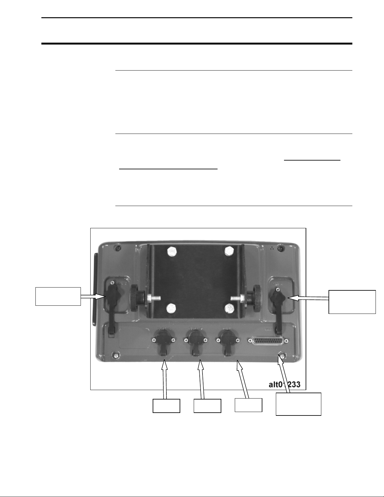
The PFadvantage has six connectors on the back of the console. The large
25-pin connector is for power and sensor connections. The AUX 1 port is
for connecting to a GPS receiver. The three 9-pin RS-232 ports (Port 1, Port
2, Port 3) are for connecting to planter or fertilizer or sprayer controller or
any other GPS compatible device. The AUX 2 port is for additional
input/output signals.
AUX Port 2
Port 3 Port 2
Port 1
Figure 3 Rear of PFadvantage
September 2003
AUX Port 1
(GPS)
25-Pin
Connector
1-7
Page 10
General
Grain Flow Sensor
PFadvantage
Ag Leader Technology
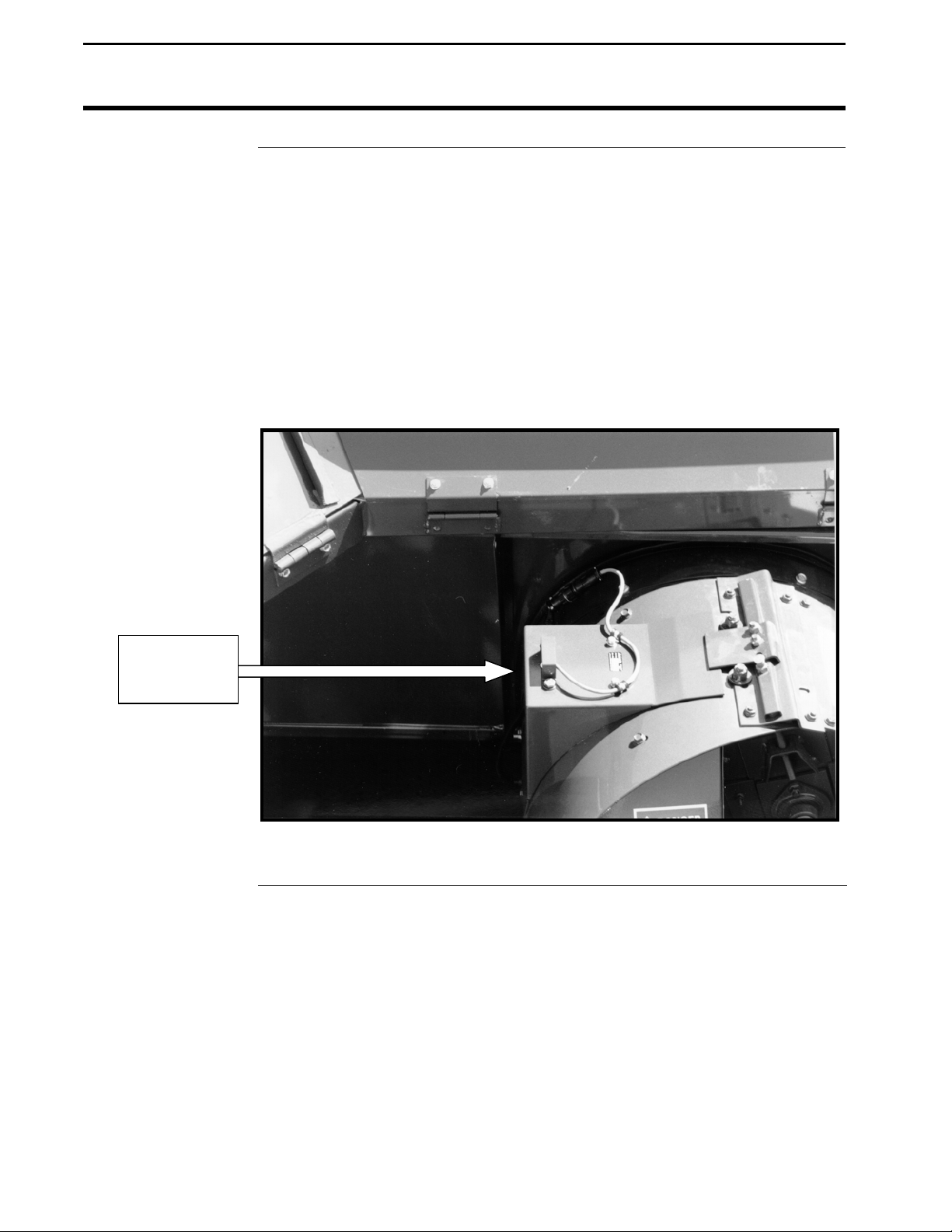
Below is an example of a grain flow sensor. Your grain flow sensor may
look different, depending on which combine model you have. On all
combines, the grain flow sensor installs on top of the clean grain elevator.
The grain flow sensor measures the grain weight in pounds as you harvest.
The clean grain paddles throw the grain, as the paddles rotate around the top
sprocket, toward the grain flow sensor. The flow sensor measures the grain
weight when the grain strikes the flow sensor impact plate.
NOTE: The flow sensor for grass seed harvest functions in the same
manner as the grain flow sensor. The grass seed flow sensor differs
only in appearance.
Grain Flow
Sensor
Figure 4: Grain flow sensor
1-8
September 2003
Page 11
PFadvantage
Ag Leader Technology
Moisture Sensor
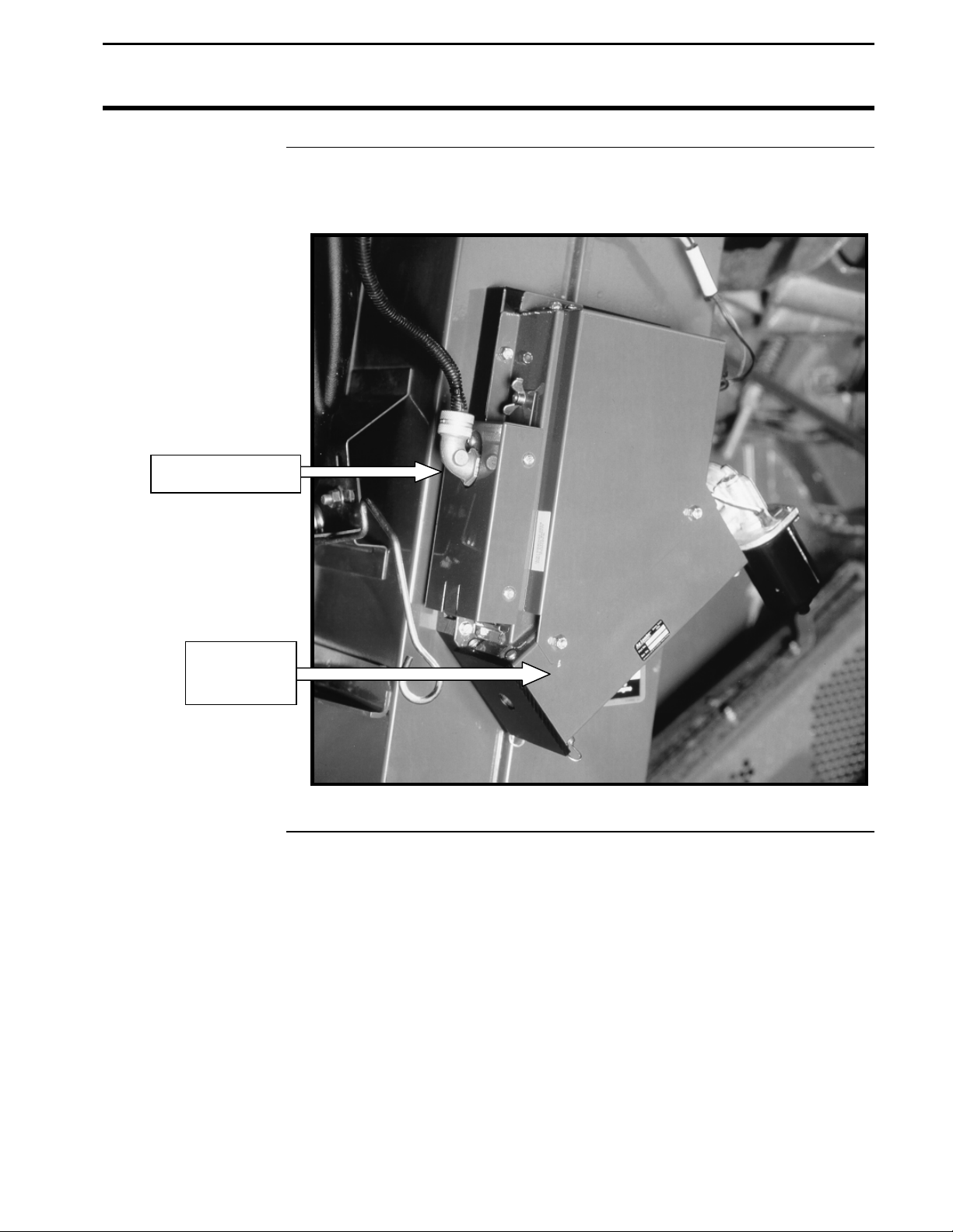
Moisture Sensor
Below is an example of the moisture sensor mounted on the side of a clean
grain elevator. The moisture sensor is installed in the elevator mount kit.
General
Elevator
Mount Kit
Figure 5: Moisture sensor
September 2003
1-9
Page 12
General
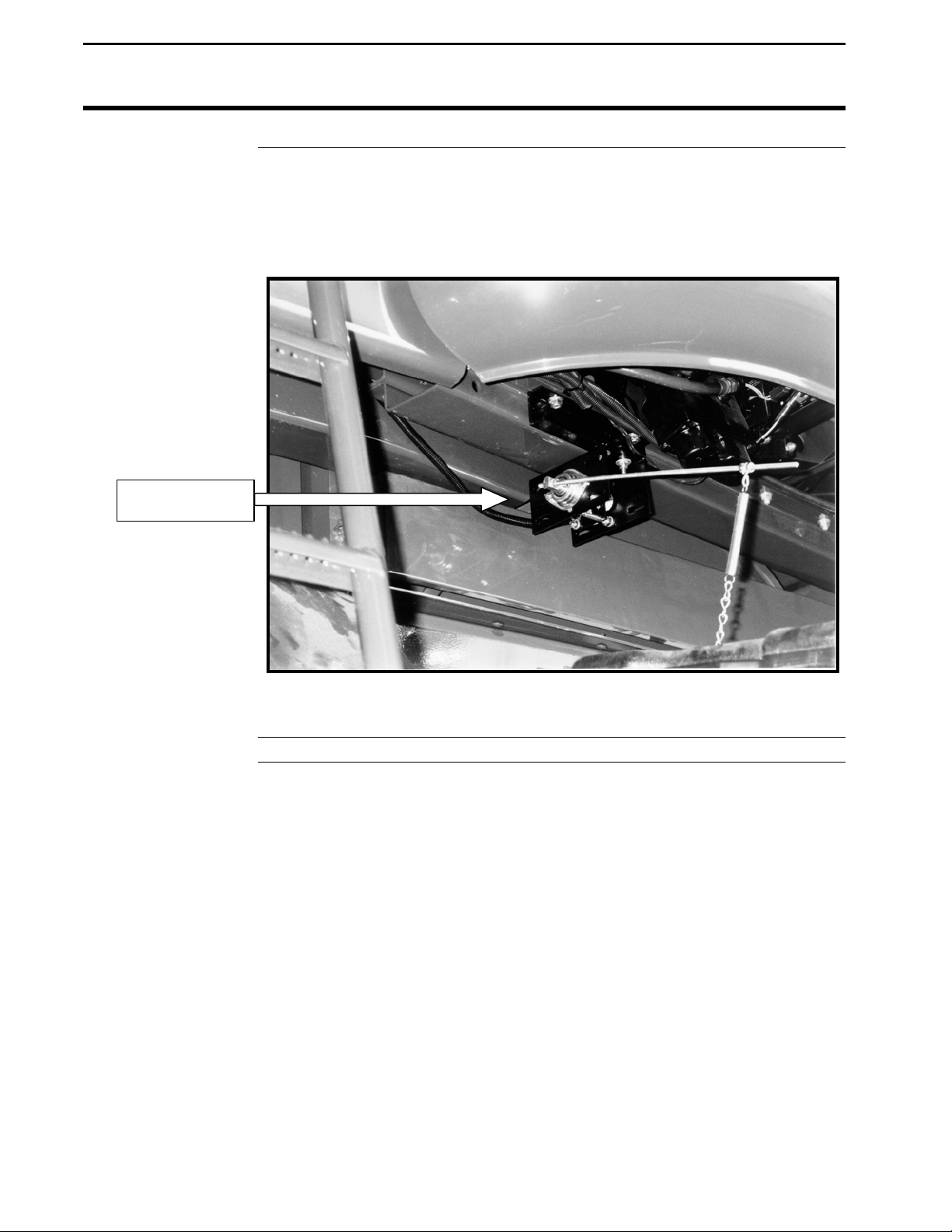
Header Height
Sensor
Header Sensor
PFadvantage
Ag Leader Technology
Below is an example of a header height sensor installed underneath a
combine cab. The header height sensor tells the monitor the position of the
combine head so that when the head is raised on the end rows, the monitor
stops counting area.
Figure 6: Header height sensor
* * *
1-10
September 2003
Page 13
PFadvantage
Ag Leader Technology
Important Notices
Section Contents
The PFadvantage must be set up before field operation, but before you
begin the setup procedures, read the following notices:
The PFadvantage is a software upgradeable monitor. Ag Leader
Technology will periodically offer free operating program upgrades to
increase the capabilities of the PFadvantage. Operating program upgrades
will be available as Internet downloadable files from the Ag Leader web
site.
Internet http://www.agleader.com
If you do not have access to the Ag Leader web site, contact your Ag
Leader dealer to request the latest operating program upgrades, or contact
our Technical Support Group (515) 232-5363 ext. 1
If you plan to make yield maps on your own computer, you will need to use
a mapping program that can process files created by the PFadvantage, such
as Ag Leader’s SMS Basic mapping program. SMS Basic is available from
on CD-ROM from your Ag Leader dealer.
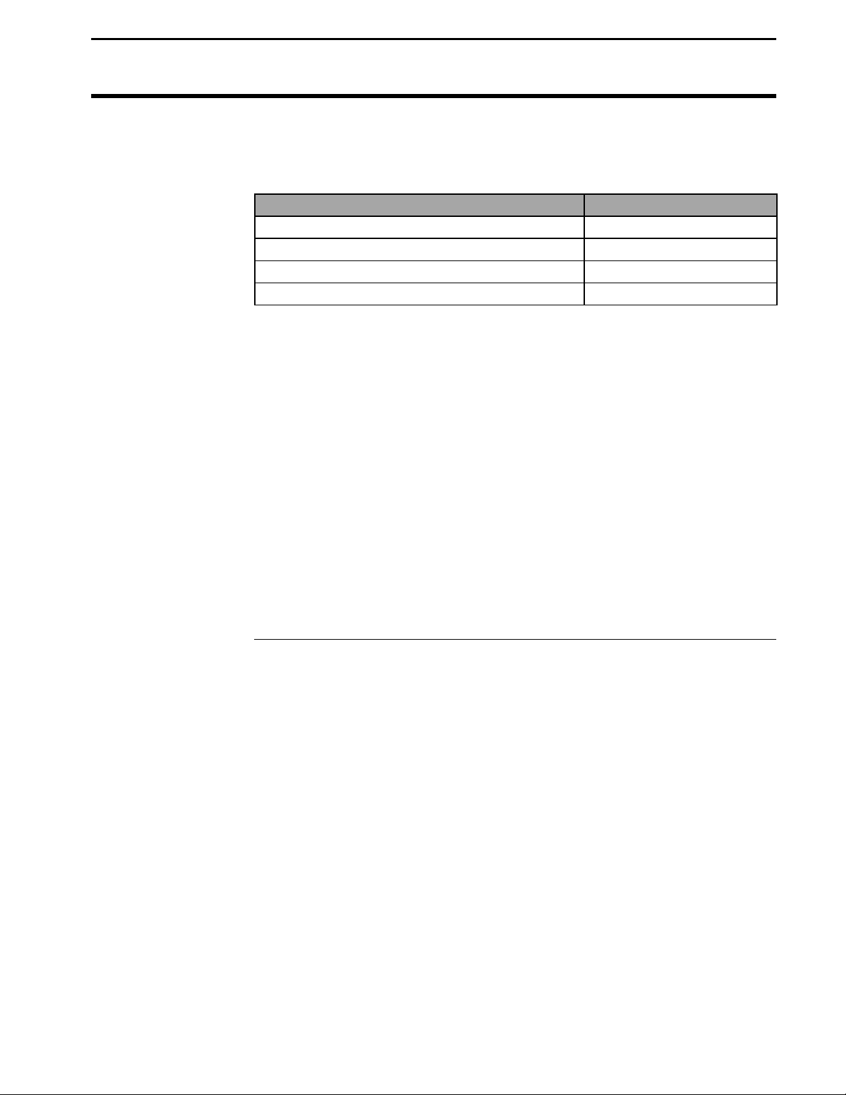
This setup section contains instructions for the following items. The
operating modes that the instructions pertain to are also listed.
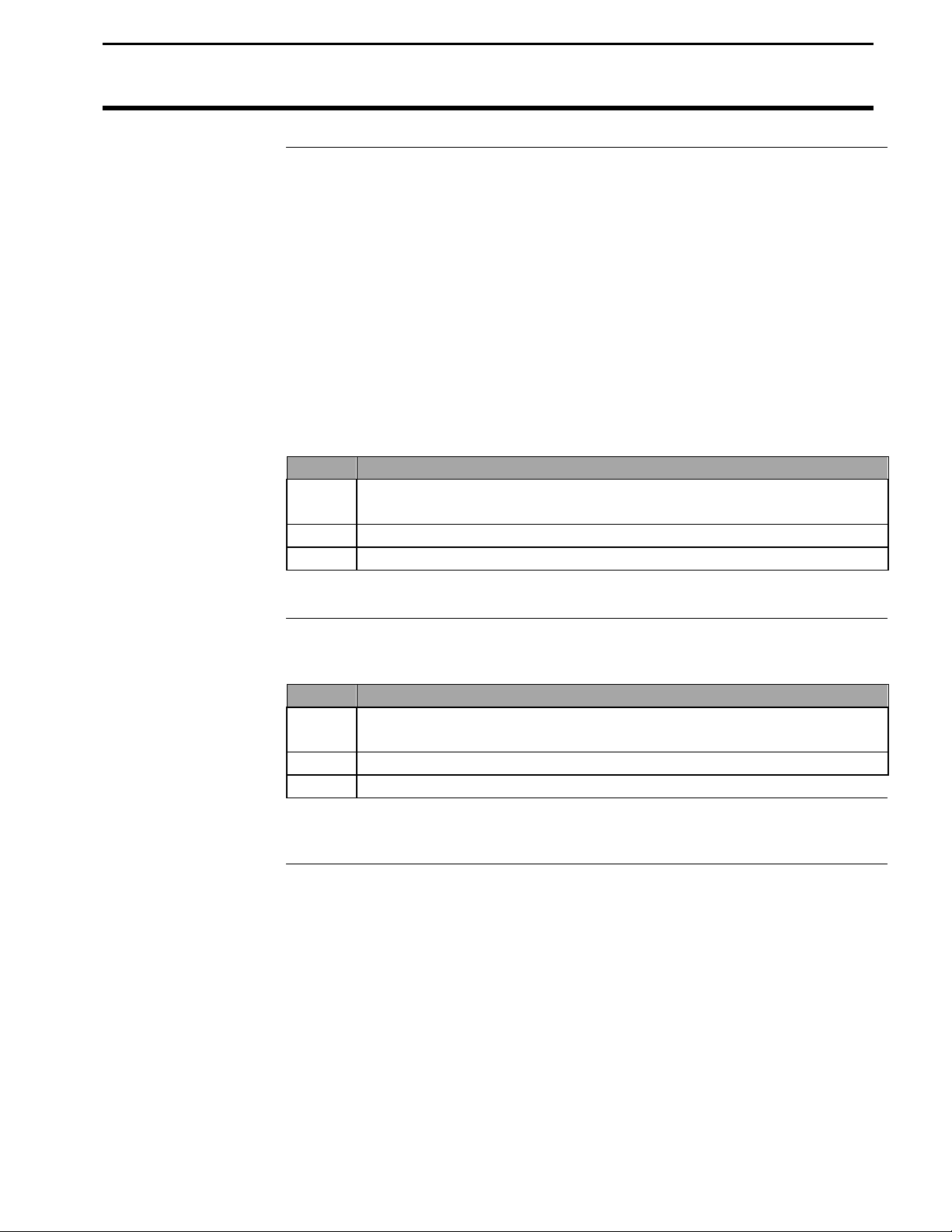
Item Operating Mode Page
Console Setup All 2-6
Card Setup All 2-8
Creating, Naming Fields and Loads All 2-12
Marker Setup All 2-17
GPS Setup All 2-19
Vehicle Setup Harvest 2-30
Grain Setup Harvest 2-34
Swath Setup Harvest 2-39
Swath Setup Site Verification 2-41
Vehicle Site Verification 2-42
Controller Setup Application Rate 2-42
Raven Controller ( with Serial Ports) Application Rate 2-44
Mid-Tech Controller Application Rate 2-49
DICKEY-john Land Manager Application Rate 2-55
DICKEY-john Seed Manager Application Rate 2-61
Rawson Accu-Rate/Accu-Plant Application Rate 2-65
Setup Overview
September 2003
2-1
Page 14
Setup Overview
Using Power
Supply
PFadvantage
Ag Leader Technology
Item Operating Mode Page
New Leader Mark III/Mark IV Application Rate 2-73
Flexicoil Flexcontrol Application Rate 2-79
Hiniker 8605 Application Rate 2-85
Teejet 844 Application Rate 2-91
Flowmeter Controller Application Rate 2-95
Direct Drive Controller for Rawson
Accu-Rate model controllers
Application Rate
The PFadvantage console does not need to be in the vehicle to set it up.
You can use the provided power supply (plugs into 120v outlet) to power
up the console inside your home or shop.
2-100
2-2
September 2003
Page 15
PFadvantage
Setup Overview
Ag Leader Technology
Order of Keys
(Harvest Mode)
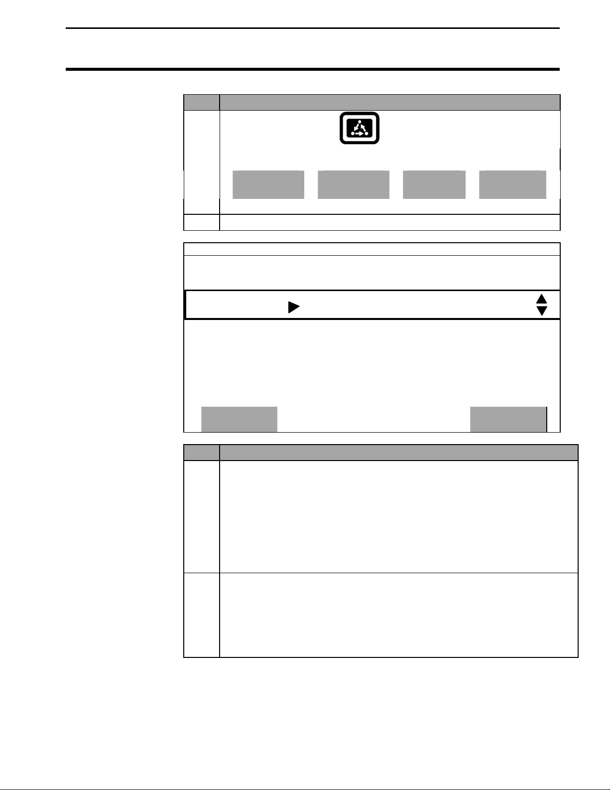
Press the MENU key until you see the following keys on
the display.
SUMMARY
Press the SETUP key to view the
following setup menu items.
All Modes
CAL
SETUP
DIAG
SETUP
OPTIONS
PRESS TO EXIT
SWATH
LOAD
GPS
MARKS
VEHICLE
Press the bottom
switch between and view the setup menu items
shown above.
MAP
GRAIN
CONSOLE
CARD
MEMORY
LEFT or RIGHT ARROW keys to
September 2003
2-3
Page 16
Setup Overview
PFadvantage
All Modes
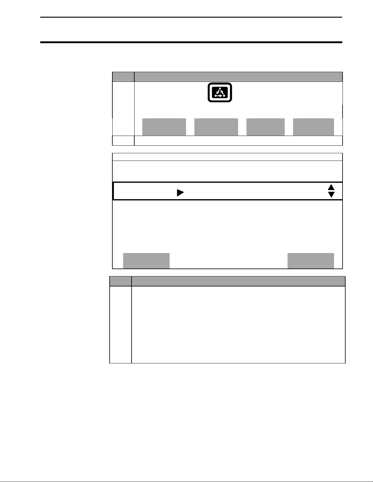
Order of Keys
(Site Verification
Mode)
Ag Leader Technology
Press MENU key
the display.
CAL
SETUP
Press the SETUP key to view
Until you see the following keys on the
DIAG
the following setup menu items.
SETUP
OPTIONS
PRESS TO EXIT
SWATH
VEHICLE
MAP
MARKS
CONSOLE
CARD
MEMORY
Press the bottom LEFT or RIGHT ARROW keys to
switch between and view the setup menu items
shown above.
LOAD
GPS
2-4
September 2003
Page 17
PFadvantage
Setup Overview
Ag Leader Technology
Order of Keys
(Application Rate
Mode)
Press the MENU key until you see on the following keys on
the display.
CAL
Press the SETUP key to view the
following setup menu items.
SETUP
All Modes
DIAG
SETUP
OPTIONS
PRESS TO EXIT
APP.RATE
CONFIG
CONSOLE
Press the bottom
MARKS
MEMORY
CARD
GPS
LEFT or RIGHT ARROW keys to
switch between and view the setup menu items
shown above.
* * *
LOAD
MAP
September 2003
2-5
Page 18
Console Setup
PFadvantage
All Modes
Introduction
The console settings are general settings that apply to all operating modes
Ag Leader Technology
and uses of the PFadvantage.
Console Setup
Screen
To view the console setup screen press the:
MENU key
SETUP key
bottom RIGHT ARROW key
CONSOLE key
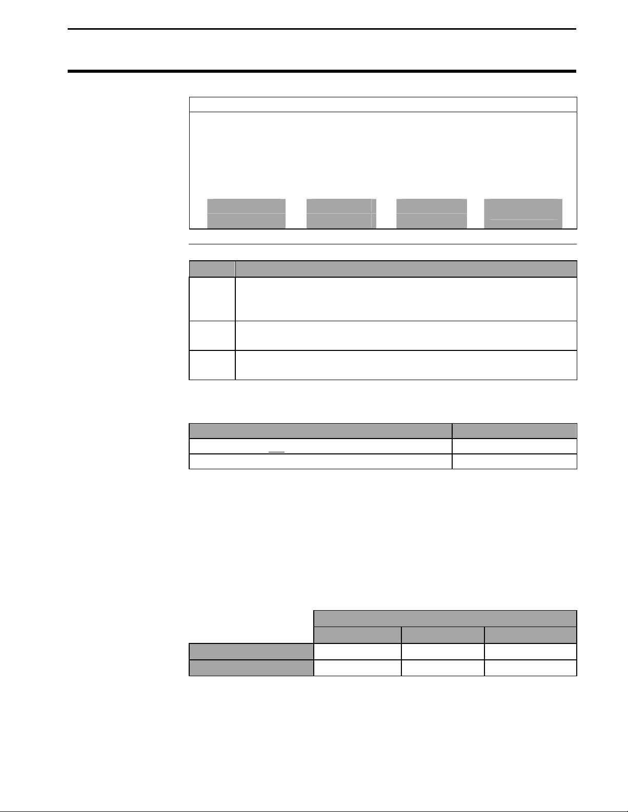
Example of console setup screen:
CONSOLE SETUP
Operating Mode GRAIN HARVEST
Month/Day/Year 11/01/2002
Time 1:15 PM
Serial Number 2002180001
Box Cal 770
Voltage Cal 490
GPS Check Sum ON
Field Marker Input INTERNAL
Display brightness 80%
Changing a Setting
EDIT
ACCEPT
Step Action
1 Use the UP or DOWN ARROW keys to select the item you want
EXIT
CANCEL
to change. The item is selected when a black filled rectangular
box surrounds the entire line.
2 Press the EDIT key and then use the UP or DOWN ARROW keys
to change the number or setting.
3 Once you have changed a setting press the ACCEPT key. Press
the EXIT key once you have made all the settings.
2-6
September 2003
Page 19

PFadvantage
Console Setup
Ag Leader Technology
Operating mode
Units of Measure
Month/Day/Year
Time
Serial number,
Box calibration,
Voltage calibration
GPS Check Sum
Field Marker
Adjust Display
Brightness
The PFadvantage has the following operating modes: Grain Harvest, Grass
Seed Harvest, Cotton Harvest, HarvestMaster™, Application Rate and Site
Verification. Upon changing the operating mode you should make sure all
setup items for that operating mode are correct.
To switch modes, you must install that modes operating firmware. The
exception is Site Verification Mode. Site Verification is available with all
other modes. See "Updating Operating Program" instructions in the
Operation Section of this manual to load different firmware. All firmware
versions are on the CD that that came with the monitor or on the web at
www.agleader.com.
The PFadvantage can display information in either Imperial or Metric units
of measure.
Set to the current date and time. These numbers should be set correctly
from the factory.
The serial number, box calibration number and voltage calibration number
can be found on the bottom side of the monitor. These numbers should be
set correctly from the factory.
GPS Check Sum setting is used to enable or disable data string error
checking. Normally set to ON.
If you are... Select
Marking field points with the PFadvantage’s
internal marker selection keys.
Marking field points with an external Ag Leader
Field Marker.
To adjust the display back lighting, scroll down to "Display brightness" and
press EDIT key. Use the UP or DOWN ARROW keys to adjust the screen
brightness and press the ACCEPT key.
All Modes
INTERNAL
EXTERNAL
* * *
September 2003
2-7
Page 20
Card Setup
PFadvantage
All Modes
Introduction
If you are using a GPS receiver, all the GPS data must be logged to a
Ag Leader Technology
memory card. If you are not using a GPS receiver, you do not need a card.
The memory card must be formatted with a DOS format. Ag Leader cards
rarely need to be formatted since they are usually DOS formatted before
they are shipped. If formatting is required, format the card in your PC
before using.
IMPORTANT:
Data must be copied to each log file before you read the card into your
computer. The monitor automatically copy copies data to the card
upon shutdown.
Card Setup Screen
To view the card setup screen press the:
MENU key
SETUP key
CARD key
Example of card setup screens:
CARD SETUP
Logging Device MEMORY CARD
Logging Interval 2 second
Log file 02110101.YLD
COPY TO SHOW ALL
FILES ON CARD
FILE NAME SIZE LAST MODIFIED
02081502.YLD 250 KB 08/15/2002
02081501.YLD 128 KB 08/15/2002
02073001.YLD 236 KB 07/30/2002
FILE ERASE
OPTIONS ALL
EDIT
ACCEPT
CARD FILES
EXIT
CANCEL
EXIT
2-8
September 2003
Page 21
PFadvantage
Card Setup
Ag Leader Technology
Changing a Setting
FILES OPTIONS
File Name 02081501.YLD
File Size 132640 bytes
Last Modified 13:42
Date 08/15/2002
COPY TO RESTORE ERASE
FILE FILE FILE
Step Action
1 Use the UP or DOWN ARROW keys to select the item you want
All Modes
EXIT
to change. The item is selected when a black filled rectangular
box surrounds the entire line.
2 Press the EDIT key and then use the UP or DOWN ARROW keys
to change the number or setting.
3 Once you have changed a setting press the ACCEPT key. Press
the EXIT key once you have made all the settings.
Logging Device
If you are using the GPS receiver with the PFadvantage you must use a
memory card to save the instantaneous GPS data.
If you... Select
NOTE: In Application Rate mode, if the PFadvantage is controlling
Do not have a GPS receiver. NONE
Do have a GPS receiver. MEMORY CARD
application rate, but you don’t want to log actual rate to card set to NONE.
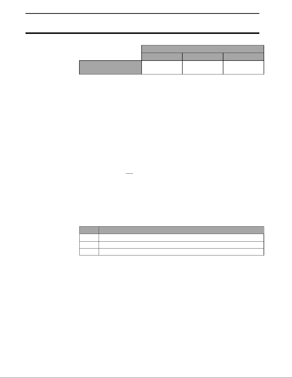
Logging Interval
This setting determines how often the GPS information is saved to the
memory card. It also affects how large an area each GPS record will
represent on a map and how many logging hours are available before the
memory card becomes full.
There are three possible settings for the logging interval.
1, 2 or 3 Seconds. The recommended setting is either two or three seconds.
3 mph
5 mph
1 sec 2 sec 3 sec
4.4 8.8 13.2
7.3 14.6 21.9
Distance Traveled (ft)
September 2003
2-9
Page 22
Card Setup
PFadvantage
All Modes
Log File
Ag Leader Technology
Ag Leader 32MB ATA
Flash Card
NOTE: The logging hours available can vary from the numbers shown above
due to the number of separate files that can be stored on the card.
The PFadvantage requires a log file to store data on a memory card. Harvest,
Site Verification and Application rate mode log files will have a “.yld”
extension. All log files will be named with the date the file was created.
Example: 02081502.yld, second file created on 08/15/2002.
IMPORTANT: Data must be copied to each log file before you read the
card into your computer. The monitor automatically copy copies data to
the card upon shutdown.
Using the Ag Leader ATA FLASH card a new log file must be created for
each day. You can not add to an old log file after a new file has been created
but you can store multiple log files on one card.
In order to log instantaneous GPS data or copy field and load data to a
memory card, a log file must be selected. Every time you turn on the
monitor, the monitor will prompt you to select or create a log file. Refer to
the steps below to select or create a log file after the monitor has been turned
on.
Step Action
1 Select Log File and press the EDIT key.
2 Select a log file or press CREATE FILE key to create a new log file.
3 With the desired file selected, press the ACCEPT key.
NOTE: After you read all the log files on your card into your computer (and
make backup copies of files), it is recommended to erase the log file(s) on the
card.
Logging Hours Available/Logging Interval
1 sec 2 sec 3 sec
400 800 1200
2-10
September 2003
Page 23
PFadvantage
Card Setup
Ag Leader Technology
Copying Data to
Log File
Restoring from
File
Step Action
Erasing File
Step Action
To copy memory to log files that are not set as the current log file, press the
SHOW FILES key and select one of the log files. Press the FILE OPTIONS
key and press the COPY TO FILE key. At the card setup screen, press the
COPY TO CARD key to copy memory to the file set as the log file (this is the
same copy to card function that automatically occurs when monitor is shut
off).
You can restore field and load data into the monitor’s memory from a log file
on a memory card.
IMPORTANT: It is dangerous to restore memory from a card because
the current data in the monitor will be replaced with the data on card.
1 Press the SHOW ALL FILES key. Select the log file and press the
FILE OPTIONS key. Press the RESTORE FILE key.
2 Press the RESTORE key again if you really want to restore the data.
3 Press the EXIT key once you are finished.
You can erase individual log files from a memory card
1 Press the SHOW ALL FILES key. Select the log file and press the
FILE OPTIONS key. Press ERASE FILE key.
2 Press the ERASE key again if you really want to erase the file.
3 Press the EXIT key once you are finished.
IMPORTANT: Pressing ERASE ALL will erase every file from the
memory card, including non-Ag Leader files.
* * *
All Modes
September 2003
2-11
Page 24
Creating, Naming Fields, Loads
PFadvantage
All Modes except App Rate
Recommendations
All the information recorded by the PFadvantage must be recorded in a
field and load. The field and load that the monitor is set on is located on the
top line of the display on the main operating screen.
Fields
It is recommended that you create all the fields and name them before you
begin to use the PFadvantage. The monitor will use the same set of fields
you create for each operating mode (harvest mode, application rate mode,
site verification) of the monitor. You can create and name your fields using
any operating mode. You should choose field names that you can use year
after year.
Loads
You may decide to create, and name loads within fields before you use the
PFadvantage however, additional loads may be created and named as
needed during field operations. Each operating mode of the PFadvantage
will have its own set of loads for each field.
Definition:
Load: A load is used to subdivide a field into smaller sections. The
Field
NOTE: If using Application Rate Mode, refer to the Controller
Setup instructions on how to create and change fields. Refer to this
section for how to name fields and loads.
monitor load is not associated with the combine tank, wagon, or
truck load.
Ag Leader Technology
Load
2-12
September 2003
Page 25
PFadvantage
Creating, Naming Fields, Loads
Ag Leader Technology
Creating and
Naming Fields
Step Action
1
Press the MENU key until the following is displayed on
the bottom of the display.
F1: DG
2 Press the FIELD key twice to view the screen below.
F1: PRESS TO EDIT NAME
FIELD
All Modes except App Rate
LOAD
ACTIVE FIELD
SELECT GRAIN
SHOW
MAP
OPTIONS
ACCEPT
Step Action
3
Naming Field
With the line displaying the field number selected (rectangular box
surrounds line), press the RIGHT ARROW key to move the cursor to
the right to enter a name. Use the UP or DOWN ARROW keys to scroll
through letters, numbers and other characters. After you have set the
character, move the cursor to the right by pressing the RIGHT ARROW
key and set a new character. You can enter up to an 8-character name.
Press the ACCEPT key once you have entered a name.
4
Setting Grain (harvest mode) or Site Type (Site Verification Mode)
To set the grain or site type for the field you must select the line
displaying the grain or site type. Press the key to the right of the line
displaying the grain or sit type to select the line. Use the UP or DOWN
ARROW keys to set the setting. Press the ACCEPT key twice, once to
accept the grain or site type, once to accept the field.
SOYBEANS
CANCEL
September 2003
2-13
Page 26

Creating, Naming Fields, Loads
PFadvantage
All Modes except App Rate
Step Action
5
Creating Fields
Press the UP ARROW key to scroll through all the fields. Once you
scroll past the last field, “Create New Field” will be displayed. Name
the field and set the grain or site type, then with “Create New Field”
displayed above the field number press the ACCEPT key to create the
new field.
6 Repeat Step 5 and create and name all your fields.
NOTE: You can have more than one grain or site type in a field.
To enter more than one grain or site type, press the FIELD key twice so that
the field is displayed in large text. Select the line displaying grain or site type
and change the setting. Press the ACCEPT key twice, once to accept the new
grain or site type and once to accept the field. The monitor will create a
separate set of loads (which are renumbered beginning with load one) for each
grain or site type in a field.
Example of load organization when two grain types are in one field in
harvest mode:
Grass Seed types
ANNUAL RYE
PERENNIAL RYE
FESCUE
ORCHARD GRASS
CRIMSON CLOVER
MEADOW FOAM
WHITE CLOVER
BENT GRASS
F10 L1 F10 L1
Ag Leader Technology
Corn Soybeans
L2
L3
Harvest grain types
SOYBEANS
CORN
WHEAT
OATS
RYE
BARLEY
SORGHUM
POPCORN
EDIBLE BEANS
CORN 2
CANOLA
RICE
SUNFLOWERS
CORN 3
CORN 4
OPT GRAIN 1
Site Verification types
PLANTING 1
PLANTING 2
PLANTING 3
SPRAYING 1
SPRAYING 2
SPRAYING 3
FERTILIZER 1
FERTILIZER 2
FERTILIZER 3
OPT SITE 1
OPT SITE 2
OPT SITE 3
OPT SITE 4
OPT SITE 5
OPT SITE 6
OPT SITE 7
L2
L3
2-14
September 2003
Page 27
PFadvantage
Creating, Naming Fields, Loads
Ag Leader Technology
Creating and
Naming Loads
Step Action
1
Press the MENU key until the following is displayed on
the bottom of the display.
2 Press the LOAD key twice to view the screen below.
F1: L1: DG
L1: PRESS TO EDIT NAME
FIELD
All Modes except App Rate
LOAD
ACTIVE LOAD
SELECT GRAIN
SHOW
MAP
OPTIONS
SOYBEANS
ACCEPT
Step Action
3
Naming Load
With the line displaying the load number selected (rectangular box
surrounds line), press the RIGHT ARROW key to move the cursor to
the right to enter a name. Use the UP or DOWN ARROW keys to
scroll through letters, numbers and other characters. After you have
set the character, move the cursor to the right by pressing the RIGHT
ARROW key and set a new character. You can enter up to an 8character name. Press the ACCEPT key once you have entered a
name.
CANCEL
September 2003
2-15
Page 28

Creating, Naming Fields, Loads
PFadvantage
All Modes except App Rate
Changing Fields
and Loads
Step Action
4
Creating Loads
Press the UP ARROW key to scroll through all the loads in the field
for the grain type. Once you scroll past the last load, “Create New
Load” will be displayed above the load number and name. Name
the load for the displayed grain/site type, then with “Create New
Load” displayed above the load number press the ACCEPT key to
create the new load.
5 Repeat step 4 and create and name all your loads.
Note: Refer to Load Setup to change grain, product or site type for an
existing load.
Changing Field
Press the FIELD key to display current field. Press the UP or DOWN
ARROW keys to scroll through the fields. Press the ACCEPT key to
change to the different field.
Changing Load
Press the LOAD key to display the current load. Press the UP or DOWN
ARROW keys to scroll through the loads. Press the ACCEPT key to
change to the different load.
Ag Leader Technology
* * *
2-16
September 2003
Page 29
PFadvantage
Marker Setup
Ag Leader Technology
Introduction
Marker Setup
Screen
If you are using an external Field Marker ignore the instructions below.
The marker setup screen is only used for making settings for the Internal
marker selection keys.
IMPORTANT:
If you are using the external field marker, make sure that under the
CONSOLE key you set Field Marker to EXTERNAL.
To view the marker setup screen press the:
MENU key
SETUP key
OPTIONS key
MARKS key
Example of marker setup screen:
MARKER SETUP
MARK NAME TYPE
MARK 1 WEEDS CONTINUOUS
MARK 2 ROCKS SPOT
MARK 3 TILE CONTINUOUS
MARK 4 WET SPOT SPOT
EDIT EDIT
NAME TYPE
ACCEPT
All Modes
EXIT
CANCEL
September 2003
2-17
Page 30

Marker Setup
PFadvantage
All Modes
Changing a Setting
Step Action
1 Use the UP or DOWN ARROW keys to select the mark. The
Ag Leader Technology
mark is selected when a black filled rectangular box surrounds the
entire line.
2 Press the EDIT NAME key to rename an existing mark. Use the
UP or DOWN ARROW keys to change a character in the name.
Use the LEFT or RIGHT ARROW keys to move the cursor over
another character within the name. Press the ACCEPT key after
you have changed the name.
3 Press the EDIT TYPE key to set the mark for continuous or spot
marking. Use the UP or DOWN ARROW keys to change the
setting. Press the ACCEPT key after you have changed the
setting.
4 Press the EXIT key once you have made all the settings.
Continuous marking
Set the marking type to continuous if the item in the field you are marking
requires you to make several marks in a row (for example: marking large
weed patches or tile lines).
When you press a mark key that is set for continuous marking, the mark
will remain on until you press the mark key again to turn off the mark.
Spot marking
Set the marking type to spot if the item in the field you are marking requires
just one mark (for example: marking a rock or tile hole).
When you press a mark key that is set for spot marking, the mark will
remain on only for a few seconds and then will automatically go off.
* * *
September 2003
2-18
Page 31

PFadvantage
GPS Setup
Ag Leader Technology
Introduction
The GPS 4100 and GPS 1000 require no initial setup to begin fieldwork.
The PFadvantage will display a “D” or “G” on the top right hand corner
of the display to indicate a GPS signal. A “D” indicates that you have a
differential signal. A “G” indicates that you have a GPS signal and you
GPS receiver are tracking four or more satellites. A lower case “g”
indicates that you have a GPS signal but your GPS receiver is tracking
only three satellites. Your GPS receiver must track four or more
satellites to get an elevation reading. You may wish to use the GPS to
show your ground speed, which requires changing the ground speed
sensor settings. Refer to Primary and Secondary Speed Sensor under
Vehicle Setup in the PFadvantage Operator’s manual for instructions.
The following provides information to change factory settings on the
GPS 4100 using the PFadvantage interface (changing GPS 1000 setting
requires the use of the GPS 1000 Utilities desktop software program.)
All Modes
General
Information
WAAS Selection
Wide Area Augmentation System (WAAS) differential correction is an
alternative to subscription based satellite differential correction.
IMPORTANT: WAAS is currently free of charge, and is
being funded by the Federal Aviation Administration (FAA).
WAAS is currently in test mode, and Ag Leader Technology
can not guarantee the availability or quality of its position
signals. Only two (2) WAAS satellites are currently covering
North America.
The following provides information to change factory settings on the
GPS 4100.
If you are going to use the WAAS option complete the following:
Step Action
1 Press Menu key on PFadvantage until SETUP is displayed,
press SETUP key.
2 Press bottom left or right arrow key until GPS is displayed and
press GPS key. You should now see the screen shown in
Figure 3.
September 2003 2-19
Page 32

GPS Setup
PFadvantage
(All Modes)
Ag Leader Technology
GPS SETUP
NMEA MESSAGE
GPS INPUT/OUTPUT
BEACON DIFFERNTIAL
SATELLITE DIFFERENTIAL
LIGHTBAR
GUIDANCE
Step Action
3 At the GPS SETUP screen (Figure 3) scroll down to Satellite
SATELLITE DIFFERENTIAL SETUP
Differential Source WAAS
Differential Provider
Satellite Frequency 0000.0000
Satellite Baud Rate 0000
Provider User Code 0
OMNISTAR Code 000000000000000000000000
Subscription Expiration 00/00/0000
Step Action
4 At the SATELLITE DIFFERENTIAL SETUP screen (Figure
5 Now press EXIT key to return to GPS SETUP screen, press
EDIT
EXIT
Figure 3. GPS SETUP Screen
Differential Mode with down arrow key and press EDIT. You
should now see the screen shown in Figure 4.
EDIT
EXIT
Figure 4. Satellite Differential Setup Screen
4) Differential Source will be highlighted, press EDIT key and
use UP or DOWN ARROW key until WAAS is displayed and
press ACCEPT key.
EXIT key again to return to the main operating screen.
September 2003
2-20
Page 33

PFadvantage
GPS Setup
Ag Leader Technology
Satellite Selection
NMEA MESSAGE
GPS INPUT/OUTPUT
BEACON DIFFERNTIAL
SATELLITE DIFFERENTIAL
LIGHTBAR
GUIDANCE
If you will be using the satellite differential option then do the following
depending on which service provider you select.
Step Action
1 Press Menu key on PFadvantage until SETUP is
displayed, press SETUP key.
2 Press bottom left or right arrow key until GPS is
displayed and press GPS key.
3 At the GPS SETUP screen scroll down to Satellite
Differential with down arrow key and press EDIT.
GPS SETUP
EDIT
All Modes
EXIT
September 2003 2-21
Page 34

GPS Setup
PFadvantage
(All Modes)
Ag Leader Technology
SATELLITE DIFFERENTIAL SETUP
Differential Source Satellite
Differential Provider Omnistar
Satellite Frequency 0000.0000
Satellite Baud Rate 0000
Provider User Code 0
OMNISTAR Code 00000000000000000000000000
If you will
be using…
Omnistar At SATELLITE DIFFERENTIAL SETUP screen
ACCEPT
Then…
Differential Source will be highlighted, press EDIT key
and use up or down arrow key until Satellite is displayed
and press ACCEPT key. Scroll down to Differential
Provider and press EDIT key. Use the UP or DOWN
ARROW key until Omnistar is displayed and press
ACCEPT key. Scroll down to Satellite Frequency and
press EDIT key. Use the UP or DOWN ARROW key to
select your region and press ACCEPT key. If you will be
using a custom frequency with this provider, scroll down
to Custom (1) and push EDIT NAME key. Use the UP or
DOWN and LEFT or RIGHT ARROW keys to name this
frequency. Push EDIT VALUE key and use the UP or
DOWN and LEFT or RIGHT ARROW keys to enter the
frequency. Push ACCEPT key. Your customized
frequency should appear as the Satellite Frequency.
CANCEL
September 2003
2-22
Page 35

PFadvantage
GPS Setup
Ag Leader Technology
SATELLITE DIFFERENTIAL SETUP
Oministar Satellite Beacon Frequencies:
Eastern USA 1556.825
Central USA 1554.497
Western USA (1) 1551.429
Western USA (2) 1551.489
Australia 1558.510
Europe 1531.230
South America (1) 1541.705
South America (2) 1541.715
Custom (1) 0000.0
Custom (2) 0000.0
ACCEPT
All Modes
CANCEL
September 2003 2-23
Page 36

GPS Setup
PFadvantage
All Modes
Ag Leader Technology
SATELLITE DIFFERENTIAL SETUP
Oministar Satellite Beacon Frequencies:
Eastern USA 1556.825
Central USA 1554.497
Western USA (1) 1551.429
Western USA (2) 1551.489
Australia 1558.510
Europe 1531.230
South America (1) 1541.705
South America (1) 1541.705
Custom (1) 0000.0
Custom (2) 0000.0
If you will
be using…
ACCEPT
EDIT
NAME
EDIT
VALUE
CANCEL
Then…
Omnistar Call the Omnistar subscription number (713-785-5850 in
the USA) and give them the number to the right of the GPS
serial number. Omnistar will then give you a 24-digit
code. Key the code into the right of Omnistar Code using
UP and DOWN ARROW keys. Once the code is entered,
press ACCEPT key to send the code to the unit. Now
press EXIT key to return to GPS SETUP screen, press
EXIT key to return to operating screen. After 30 minutes,
the receiver should start receiving corrections and display a
“D” in the upper right hand corner of the PFadvantage.
2-24
September 2003
Page 37

PFadvantage
GPS Setup
Ag Leader Technology
SATELLITE DIFFERENTIAL SETUP
Differential Source Satellite
Differential Provider RACAL
Satellite Frequency 1553.345000
Satellite Baud Rate 1200
Provider User Code 8111
OMNISTAR Code 00000000000000000000000000
If you will
be using …
THALES
(RACAL)
ACCEPT
CANCEL
Then…
At SATELLITE DIFFERENTIAL SETUP screen
Differential Source will be highlighted press EDIT key
and use UP or DOWN ARROW key until Satellite is
displayed and press ACCEPT key. Scroll down to
Differential Provider and press EDIT key. Use the UP
or DOWN ARROW key until RACAL is displayed and
press ACCEPT key. Scroll down to Satellite Frequency
and press EDIT key. Use the UP or DOWN ARROW
key to select your region and press ACCEPT key. If
you will be using a custom frequency with this provider,
scroll down to Custom (1) and push EDIT NAME key.
Use the UP or DOWN and LEFT or RIGHT ARROW
keys to name this frequency. Push EDIT VALUE key
and use the UP or DOWN and LEFT or RIGHT
ARROW keys to enter the frequency. Push ACCEPT
key. Your customized frequency should appear as the
Satellite Frequency.
All Modes
September 2003
2-25
Page 38

GPS Setup
PFadvantage
All Modes
Ag Leader Technology
SATELLITE DIFFERENTIAL SETUP
RACAL Satellite Beacon Frequencies:
North American East 1553.345
North American Mntn 1554.350
North American West 1556.225
Australia 1558.525
Europe 1531.210
South Africa 1552.640
Custom (1) 0000.0
Custom (2) 0000.0
Custom (3) 0000.0
Custom (4) 0000.0
ACCEPT
SATELLITE DIFFERENTIAL SETUP
RACAL Satellite Beacon Frequencies:
North American East 1553.345
North American Mntn 1554.350
North American West 1556.225
Australia 1558.525
Europe 1531.210
South Africa 1552.640
Custom (1) 0000.0
Custom (2) 0000.0
Custom (3) 0000.0
Custom (4) 0000.0
If you will
ACCEPT
Then…
EDIT
NAME
EDIT
VALUE
be using …
THALES
(RACAL)
Call the THALES (RACAL) subscription number (713-784-
4482 in the USA) and give them the number to the right of the
GPS serial number. THALES (RACAL) will activate a code
for the serial number that was given. After the serial number
is called in, press the EXIT key to return to operating screen.
Within 15 to 30 minutes the receiver should start receiving
corrections from THALES (RACAL). A “D” should appear in
the upper right hand corner of the PFadvantage.
CANCEL
CANCEL
2-26
September 2003
Page 39

PFadvantage
GPS Setup
Ag Leader Technology
SATELLITE DIFFERENTIAL SETUP
Differential Source Satellite
Differential Provider RACAL
Satellite Frequency 1553.345000
Satellite Baud Rate 1200
Provider User Code 8111
OMNISTAR Code 00000000000000000000000000
Beacon Selection
The settings for beacon selection are Auto range, Auto Power and Manual.
• Auto Range: This is the default setting. In this setting the receiver keeps
a record of the closest three beacons within the receivers range. It then
selects a beacon based on the ranking of the beacon in memory.
• Auto Power: The receiver keeps a record of the three strongest beacons in
its range. It then selects a beacon based on the ranking of the available
beacons.
• Manual: Allows you to input frequencies for two beacons.
To change Beacon Selection complete the following steps:
ACCEPT
All Modes
CANCEL
Step Action
1 Press Menu key on PFadvantage until SETUP is displayed
and press SETUP.
2 Press bottom left or right arrow key until GPS is displayed
and press GPS key.
September 2003
2-27
Page 40

GPS Setup
PFadvantage
All Modes
GPS SETUP
NMEA MESSAGE
GPS INPUT/OUTPUT
BEACON DIFFERNTIAL
SATELLITE DIFFERNTIAL
LIGHTBAR
GUIDANCE
EDIT
Step Action
3 From the GPS SETUP screen scroll down to BEACON
DIFFERNTIAL and press EDIT key. Use up or down
arrow keys to set mode.
4 After setting Auto Power mode, push ACCEPT key and
then EXIT.
Ag Leader Technology
EXIT
BEACON SETUP
Mode: Auto Power
Channel 0 Frequency AUTO
Channel 1 Frequency AUTO
ACCEPT
EXIT
2-28
September 2003
Page 41

PFadvantage
GPS Setup
Ag Leader Technology
BEACON SETUP
Mode: Manual
Channel 0 Frequency 300.0
Channel 1 Frequency 300.0
ACCEPT
Step Action
5 If you are setting to Manual push ACCEPT key then use
down arrow key to scroll to Channel 0 Frequency and
press EDIT key. Use the up or down arrow key to set
desired frequency and press ACCEPT key. Scroll down
to Channel 1 Frequency and press EDIT key. Use up or
down arrow keys to set desired frequency and press
ACCEPT key.
6 Press the EXIT key two times to return to operating
screen.
***
All Modes
EXIT
September 2003
2-29
Page 42

Vehicle Setup
PFadvantage
Harvest Mode
Introduction
For each operating mode, there are different items to setup in the vehicle
Ag Leader Technology
setting screen. Below are the setup items for the harvest mode. Refer to
your Initial Calibration Sheet to make the correct settings.
Vehicle Setup
Screen
To view the vehicle setup screen press the:
MENU key
SETUP key
bottom RIGHT ARROW key
VEHICLE key
Example of vehicle setup screen:
VEHICLE SETUP
Elevator pulses / revolution 1 Pulses
Sprocket teeth 8 Teeth
Combine scale factor 1.0
Area count stop beeps 20 Beeps
Expand grain below dry % NO
Sensor calibration 1400
T1 10
T2 5
T3 8
Primary speed sensor WHEELS
Secondary speed sensor --------Speed sensor pulses / 100 ft 2000 Pulses
EDIT
ACCEPT
EXIT
CANCEL
2-30
September 2003
Page 43

PFadvantage
Vehicle Setup
Ag Leader Technology
Changing a Setting
Elevator
pulses/revolution
Sprocket teeth
Combine scale
factor
Step Action
1 Use the UP or DOWN ARROW keys to select the item you want
to change. The item is selected when a black filled rectangular
box surrounds the entire line.
2 Press the EDIT key and then use the UP or DOWN ARROW keys
to change the number or setting.
3 Once you have changed a setting press the ACCEPT key. Press
the EXIT key once you have made all the settings.
Refer to the Initial Calibration Sheet for the correct setting for your
combine.
Refer to the Initial Calibration Sheet for the correct setting for your
combine.
Refer to the Initial Calibration Sheet for the correct setting for your
combine.
IMPORTANT:
• Never change the scale factor during harvest. Doing so will cause
the monitor to lose calibration accuracy and you will have to set the
monitor on different grain types and recalibrate every grain type.
• All of your calibration loads and data loads must be harvested using
the same scale factor setting otherwise you will have severe
calibration problems that possibly can not be corrected.
Harvest Mode
September 2003
2-31
Page 44

Vehicle Setup
PFadvantage
Harvest Mode
Area count stop
beeps
Expand grain below
Dry %
Sensor calibration
T1, T2, T3
This setting is for the number of times the monitor beeps when the head is
raised at the end of a pass and the monitor stops counting area.
NOTE: The recommended setting is 20. Set this number high enough so
that after the head is raised at the end of a pass, the beeps continue until the
combine is completely turned around and the head is lowered to start the
new pass. This gives the operator an audible signal that the head is
lowered enough to begin counting area again.
If you select . . . Then . . .
No, You prevent the monitor from adding bushels to grain
that is dryer than the dry percent moisture by which dry
bushels are calculated. This calculates all yields in terms
of actual bushels available for you to sell.
(Recommended setting).
Yes, The monitor shows a yield comparison of all loads at
the dry percent moisture. This increases the bushels of
the grain harvested below the dry percent moisture to
account for moisture lost because of excessive dryness
of the grain.
NOTE: This setting applies to all loads and grains in the monitor. It can be
changed from NO to YES and vice-versa at any time.
Refer to the Initial Calibration Sheet for the correct setting for your
combine.
NOTE: If you replace the flow sensor, you must change this setting to the
value of the new sensor calibration number for the new flow sensor. The
sensor calibration number is listed on the flow sensor serial number tag.
Refer to the Initial Calibration Sheet for the correct setting for your
combine.
Ag Leader Technology
2-32
September 2003
Page 45
PFadvantage
Vehicle Setup
Ag Leader Technology
Primary and
Secondary speed
sensor
Speed sensor pulses
/ 100 ft.
The monitor has four different primary speed settings. They are listed
below.
Ground Speed Sensor Primary Speed Sensor
Speed sensor on transmission WHEEL
Speed sensor on tracks TRACK
Radar gun RADAR
GPS receiver GPS
If you choose GPS as your primary speed sensor, you need to set the
secondary speed sensor to WHEEL, TRACK, or RADAR. If the GPS
signal is lost, the monitor will use the secondary speed sensor. If you do
not choose GPS as your primary speed sensor you can not set the secondary
speed sensor.
It is not recommended that you change this setting. This number is the
distance calibration number that is set when you perform a distance
calibration for WHEEL, TRACK or RADAR. Refer to the calibrating
distance instructions in the Calibration section. You must calibrate distance
for a WHEEL, TRACK or RADAR setting for accurate ground speed.
NOTE: If you want to use a radar gun, contact an Ag Leader Technology
dealer and purchase a special adapter cable for your radar gun.
Harvest Mode
* * *
September 2003
2-33
Page 46

Grain Setup
PFadvantage
Harvest Mode
Grain Setup
NOTE: Grass Seed monitors are setup using the same
Ag Leader Technology
procedures as Grain.
To view the grain setup screen press the:
Screen
MENU key
SETUP key
GRAIN key
Example of grain setup screen:
GRAIN SETUP
GRAIN NAME TYPE
GRAIN 1 SOYBEANS Low Flow
GRAIN 2 CORN Hi Flow
GRAIN 3 WHEAT Low Flow
GRAIN 4 OATS Low Flow
EDIT EDIT
NAME SETTINGS
ACCEPT
EXIT
CANCEL
2-34
September 2003
Page 47

PFadvantage
Grain Setup
Ag Leader Technology
Changing a Setting
Step Action
1 Use the UP or DOWN ARROW keys to select the grain. The
grain is selected when a black filled rectangular box surrounds the
entire line.
2 Press the EDIT SETTINGS key to move to another screen and
change the settings for the selected grain. Refer to the screen
below.
3 Press the EDIT NAME key to rename an existing grain (can not
rename SOYBEANS, CORN, or WHEAT). Use the UP or
DOWN ARROW keys to change a character in the name. Use the
LEFT or RIGHT ARROW keys to move the cursor over another
character within the name. Once you have changed the grain
name press the ACCEPT key.
4 Press the EXIT key once you have made all the settings.
Example of grain settings screen:
GRAIN SETTINGS: CORN
Dry lbs / bu 56 lb / bu
Dry moisture 13.0 %
Moisture offset 4.7 %
Stop height 54
M1 400
S1 50
EDIT
ACCEPT
Harvest Mode
EXIT
CANCEL
September 2003
2-35
Page 48

Grain Setup
PFadvantage
Harvest Mode
Dry lbs / bu
Dry moisture
Scale Factor
Moisture offset
Stop Height
M1
S1
Setting Initial C
Numbers
Ag Leader Technology
This setting is the pounds / bushel value that the monitor uses to calculate
bushels. You can change this setting for all grains except corn (56 lbs / bu),
soybeans (60 lbs / bu) and wheat (60 lbs / bu).
This setting is the moisture value that the monitor uses to calculate dry
bushels.
Example:
Corn – 15%
Soybeans – 13%
For grass seed the recommended setting is 1. Settings are 1, 10, 100.
Refer to the Initial Calibration Sheet for the correct setting. Do not readjust
the moisture offset number after you have performed a moisture calibration.
This setting determines how high the combine head must be raised to make
the monitor stop counting area. This number can be automatically set under
the CAL, STOP HGT key.
Refer to the Initial Calibration Sheet for the correct setting.
Refer to the Initial Calibration Sheet for the correct setting.
The 11 C Numbers, C1 through C11 determine the pounds of grain that the
monitor calculates. The C numbers initially should be set to the same
values that appear on your Initial Calibration Sheet, but they will change
and become more accurate after you have calibrated.
Do not change the C numbers after you have calibrated.
You only need to set the C11 number to its initial value. When you set the
C11 number, the C2-C10 numbers will automatically change to the correct
value. Do not set the C1 number. It is adjusted automatically when you do
a vibration calibration.
2-36
September 2003
Page 49

PFadvantage
Grain Setup
Ag Leader Technology
Changing C11
Step Action
1 You must display the weight calibration screen.
Press the following keys to view the weight calibration screen:
MENU key
CAL key
WEIGHT key
2 Refer to the screens on the next page and press the UP or DOWN
ARROW keys to set a grain type that you will harvest. Press the
SHOW CAL NUMBERS key.
3 Use the DOWN ARROW key to select C11 number (a line is
selected when the entire line is surrounded by a black filled box).
4 Press the EDIT key. Use the UP or DOWN ARROW keys to set
the correct number according to the Initial Calibration Sheet.
Press the ACCEPT key.
5 Press the EXIT key once to return to the previous screen. Repeat
steps 2-4 and set C11 for all the grain types you will harvest.
6 Press the EXIT key twice to return to the main operating screen.
NOTE: You may not be able to set C11 to the exact number that is on the
Initial Calibration Sheet. C2-C10 numbers also may not exactly agree
with the Initial Calibration Sheet. If this is the case, set C11 as close to the
initial number as possible.
Harvest Mode
September 2003
2-37
Page 50

Grain Setup
PFadvantage
Harvest Mode
Ag Leader Technology
GRAIN CALIBRATION
SELECT GRAIN:
SOYBEANS
ENTER
WEIGHT
SHOW CAL
LOADS
SHOW CAL
NUMBERS
EXIT
GRAIN CALIBRATION: SOYBEANS
CALIBRATION NUMBERS
C1 0
C2 250
C3 500
C4 750
C5 1000
C6 1250
C7 1500
C8 1750
C9 2000
C10 2250
C11 2500
EDIT
ACCEPT
CAL
ON/OFF
PERFORM
CAL
* * *
EXIT
CANCEL
2-38
September 2003
Page 51

PFadvantage
Swath Setup
Ag Leader Technology
Introduction
Swath Setup
Screen
The swath setup screen is used to set the permanent, full swath of your
head. Do not
adjust the swath setting on this screen when you encounter a
partial swath while harvesting. Refer to the Swath Setting instructions in
Operation Section and select swath as a display item and set a partial swath.
To view the swath setup screen press the:
MENU key
SETUP key
SWATH key
Example of swath setup screen:
SWATH SETUP
GRAIN # ROWS SPACING FULL SWATH
SOYBEANS 24 12 in 24 ft 0 in
CORN 8 30 in 20 ft 0 in
WHEAT 24 12 in 24 ft 0 in
OATS 24 12 in 24 ft 0 in
EDIT EDIT
# ROWS SPACING
ACCEPT
Harvest Mode
EXIT
CANCEL
September 2003
2-39
Page 52

Swath Setup
PFadvantage
Harvest Mode
Ag Leader Technology
Changing a Setting Step Action
1 Use the UP or DOWN ARROW keys to select the grain. The
grain is selected when a black filled rectangular box surrounds the
entire line.
2 Press the EDIT # ROWS key to change the number of rows. Use
the UP or DOWN ARROW keys to change the number. Press the
ACCEPT key after you have changed the number.
3 Press the EDIT SPACING key to change the row spacing. Use the
UP or DOWN ARROW keys to change the number. Press the
ACCEPT key after you have changed the number.
4 Press the EXIT key once you have made all the settings.
Recommendations for Row Crop Heads:
• For row crops, set your row space to the planted row spacing and your
number of rows to the number of total rows of your combine head.
Recommendations for Cutting Platform Heads:
Row Crops
• For row crops, set your row space to the planted row spacing and your
number of rows to the number of total rows your cutting platform will
cut.
Non-rowed crops
• Set the swath in the monitor to one foot less than the actual swath width
of the head because you can rarely maintain a constant full swath while
harvesting.
Example: If your cutting platform head is 20 actual feet, set the
monitor’s swath to 19 feet by setting the row space to 12 inches and the
number of rows to 19.
• Set the monitor on a row space of 12 inches and a number of rows that
adds up to the correct swath. Setting the row space to 12 inches for
cutting platforms allows you to reduce the cutting swath by easier-to-see
one-foot increments when you are harvesting a partial swath
Refer to the Swath Setting instructions in the Operation Section for more
information about partial swath.
* * *
2-40
September 2003
Page 53

PFadvantage
Swath Setup
Ag Leader Technology
Introduction
Swath Setup
Screen
Recommendations
The swath setup screen is used to set the permanent, full swath of your
application equipment. Do not adjust the swath setting on this screen when
you encounter a partial swath in the field. Refer to the Swath Setting
instructions in Operation Section and select swath as a display item and set
a partial swath.
NOTE: If you do not want to count area, you do not need to set the
swath.
Refer to the swath setup instructions for harvest mode for instructions on
viewing the swath setup screen and setting the swath.
To enter a swath setting, you must enter a number of rows setting and a row
spacing setting for the product you are applying.
Application equipment that uses row units
If your application equipment is applying the product with row units, then
enter the number of rows and row spacing of the application equipment.
Application equipment that uses boom sections
If your application equipment is applying the product using boom sections
enter the width of the boom section in inches for the row spacing setting.
Enter the total number of booms for the number of rows setting. If your
boom sections are not all the same width, enter twelve inches for the row
spacing setting and a number rows setting that makes the total swath equal
the full swath of the application equipment.
Application equipment that uses a spreader mechanism
If your application equipment is applying the product using a spreading
mechanism enter twelve inches for the row spacing setting and a number
rows setting that makes the total swath equal the full swath of the
application equipment.
Site Verification Mode
* * *
September 2003
2-41
Page 54

Vehicle Setup
PFadvantage
Site Verification Mode
Introduction
For each operating mode, there are different items to setup in the vehicle
Ag Leader Technology
setting screen. Below are the setup items for the site verification mode.
Vehicle Setup
Screen
To view the vehicle setup screen, press the MENU key, SETUP key and
VEHICLE key to view the following:
VEHICLE SETUP
TRACTOR
TRUCK
ATV
OPTIONAL 1
OPTIONAL 2
OPTIONAL 3
OPTIONAL 4
ACCEPT EDIT EDIT
VEHICLE NAME SETTINGS
Use the UP or DOWN ARROW key select a vehicle type. Press EDIT
CANCEL
NAME key. Use the UP or DOWN ARROW key to name the vehicle type
and press SAVE NAME key.
To edit vehicle settings press EDIT SETTINGS key to view the following:
VEHICLE SETUP
Primary speed sensor WHEELS
Secondary speed sensor -------- Speed sensor pulses / 100 ft 2000 Pulses
Area count stop beeps 20 Beeps
Area Count STANDARD
Stop height 8
EDIT
ACCEPT
EXIT
CANCEL
2-42
September 2003
Page 55

PFadvantage
Vehicle Setup
Ag Leader Technology
Area count stop
beeps
Primary and
Secondary speed
sensor
Press the UP or DOWN ARROW key to scroll down to highlight a setting
and press the EDIT key to change a setting, then press ACCEPT key. After
making changes, press EXIT key.
Choose the vehicle you want to use and press ACCEPT VEHICLE key.
This setting is for the number of times the monitor beeps when the monitor
stops counting area at the end of a pass.
The monitor has four different primary speed settings. They are listed
below.
Ground Speed Sensor Primary Speed Sensor
Speed sensor on transmission WHEEL
Speed sensor on tracks TRACK
Radar gun RADAR
GPS receiver GPS
Site Verification Mode
***
September 2003
2-43
Page 56

Raven Controller (with Serial Port)
PFadvantage
Application Rate Mode
Cable attachment
for Raven
controllers with
serial ports
ATV Battery Power Cable
(p.n. 2000497-2)
Setup for Raven
controllers with
serial ports
The Raven Serial Cable enables the PFadvantage to control the rate. It
also provides swath width (based on the number of booms on), actual
rate and area count status (based on Master Switch) information to the
PF.
Complete the following steps to set up for Raven – Sidekick, 440, 450,
460, 660, 700, 710, 750, 760 controllers with
A separate configuration of settings should be created for every product
applied. A maximum of 16 different configurations can be created. The
screen below illustrates two configurations set up for a Raven 440.
1. Press SETUP key. Press APP RATE CONFIG key. A screen
similar to the one below should appear.
Ag Leader Technology
NOTE: If your Raven console has a serial port, it
will be on the back of the console. It is a nine-pin
rectangular computer port. The Raven 750 and
760 serial port is built-in the main wiring harness.
Not all Ravens consoles have a serial port.
PFadvantage
Cable attachment from Raven console to monitor
Port 3
Raven Serial Cable (p.n. 2000944)
Raven Console
serial ports.
2-44
September 2003
Page 57

PFadvantage
Raven Controller (with Serial Port)
Ag Leader Technology
APP RATE CONFIG
PRODUCT CONTROLLER CHANNEL
Treflan 440 Rate 1
Roundup 440 Rate 1
EDIT
SETTINGS
Press CREATE NEW key to set up a new configuration or
select an existing configuration and press the EDIT
SETTINGS key. A new screen appears with the following
settings. Select each setting and press EDIT key to change the
settings.
Controller Make: Set to RAVEN. This setting can not be
changed once the configuration is used by one or more fields.
Controller Model: Set to the Raven model you have. For
example: 440 or 460 etc. This setting can not be changed once
the configuration is used by one or more fields.
Product: Press EDIT key. You can select an existing product
and press ACCEPT key or create a new product by pressing
CREATE NEW key. Press EDIT NAME key and enter name
of product. Use Left or Right Arrow keys to select a character.
Use Up or Down Arrow key to change the character. To erase
a character in the name, highlight that character and use UP or
DOWN ARROW key to scroll to the blank space between "9"
and "A". Set every character and press ACCEPT key twice.
Units: Usually set to GALLONS. Set to Units/Acre of
application.
Ground Speed Sensor: Set primary speed sensor to GPS.
SERIAL is not recommended. RADAR is an option but you
will need additional cabling to connect the radar to your
monitor. All Ag Leader GPS except GPS 1000 will work for
ground speed.
Application Rate Mode
CREATE
NEW
Note: This setting affects all configurations.
DELETE
EXIT
September 2003
2-45
Page 58

Raven Controller (with Serial Port)
PFadvantage
Application Rate Mode
Ag Leader Technology
App Distance From GPS: Set to distance between where
product exits applicator and position of GPS antenna on
vehicle. Example: If spray boom is 20 feet behind GPS
antenna set to 20 feet back. Press DOWN ARROW key to set
feet back, UP ARROW key to set feet forward.
Full Swath: Ignore setting. Swath automatically comes from
serial port of Raven. The swath on the PF automatically
changes as boom sections are turned ON or OFF.
Tgt Units: Contrler Units: Normally set to 1:1.0000. This
ratio is used to convert the units in a target file (.tgt) to the
units of application.
Example: Tgt file in pints/ac of Treflan, Raven applies based
on gallons/ac. If tank mix is 1 pint of Treflan / 10 gallon
water, then set to 1:10.0000. The PFadvantage will read the
pints/acre rate out of the tgt file, multiply it by ten to convert
it to gallons/ac and send that rate to the Raven console as the
rate to be applied.
Target Rate Increment: Determines increment value by
which you can change the manual target rate with each press
of Up or Down arrow keys. Choices are 0.1, 1.0, 10.0, 100.0,
500.0, 1000.0, 5000.0 or 10000.0.
Actual Rate Scale Factor: This setting is required to prevent
data loss in the log file (YLD file) when the units/sec of
application get above 3. Use the chart below for setting. The
rate actually applied and rate displayed on PFadvantage is
unaffected by this setting. When the log file is mapped in Ag
Leader's SMS mapping program, the mapped actual rate will
be 1/10th of the real rate if the Actual Rate Scale Factor is
0.100. If it is 0.010, the mapped actual rate will be 1/100
real rate. The mapped actual rate can be scaled back up in
SMS. The summary actual rate in SMS is unaffected by this
setting.
th
the
2-46
September 2003
Page 59

PFadvantage
Raven Controller (with Serial Port)
Ag Leader Technology
Avg. Speed Swath Application Rate between Scale Factor
0-25 mph 0-80 ft 0-10 units/ac
0-10 mph 0-80 ft 11-100 units/ac
11-15 mph 0-50 ft 11-100 units/ac
11-15 mph 51-80 ft 11-100 units/ac
16-25 mph 0-80 ft 11-100 units/ac
0-25 mph 0-80 ft 101-500 units/ac
0-10 mph 0-80 ft 501-1000 units/ac
11-15 mph 0-50 ft 501-1000 units/ac
11-15 mph 51-80 ft 501-1000 units/ac
16-25 mph 0-80 ft 501-1000 units/ac
0-25 mph 0-80 ft 1001+ units/ac
2. If you have a 440, 450, or 460 ignore this step, otherwise press
CONTRLER SETTINGS key. Set the following:
Controller Channel: Set to channel of Raven to record or
control rate.
Controller Operating Mode: Set to liquid or granular,
whichever type the Raven console is controlling.
3. Press EXIT key to return to screen with ADVANCED
SETTINGS key on bottom. Press the ADVANCED
SETTINGS key.
Target Rate Outside Field: This only pertains to using a
.tgt prescription file.
Set to ZERO if want rate outside field to be zero.
Set to USE LAST if want rate to be the last rate used at
the time the vehicle is detected outside the field. This is
useful when the vehicle is being falsely detected outside
of the field during the outside pass.
Set to TGT DEFAULT if want rate outside field to be the
default rate stored in the .tgt prescription file.
Controller Time Delay: Set to 3 seconds. This is delay of
controller to change application equipment to new rate + 2
seconds.
Application Rate Mode
1.000
1.000
1.000
0.100
0.100
0.100
0.100
0.100
0.010
0.010
0.010
September 2003
2-47
Page 60

Raven Controller (with Serial Port)
PFadvantage
Application Rate Mode
4. This completes all the settings for one configuration. Press
EXIT key twice to return to screen showing all configurations
or press EXIT key 3 times and menu key to return to main
operating system.
Activating
Configuration and
Setting .tgt
Prescription File
Settings for Raven.
Additional
Instructions
5. Exit back to main screen.
Under Data Menu key, set Baud = 9600, Trig = 1, Unit = sec,
Dlog = ON. To turn the rate change alarm OFF set Rate = OFF.
On some Ravens the Dlog setting has to be reset when the
console is turned ON.
For more information on setting Target Rate, display items,
creating and using .tgt prescription files and logging actual rate see
the Operation Section in this manual.
Ag Leader Technology
Actual Rate Units: Ignore this setting.
Log Actual Rate: Set to YES to log actual rate to card.
Set to No, otherwise.
a) Press FIELD key twice.
b) Select appropriate field and press VIEW CONFIG key.
c) Select appropriate product/controller configuration and
press ACTIVE ON/OFF key to check it as active. (All
other configurations must be unchecked first).
d) If you will be using a .tgt prescription file. Press EDIT
TGT FILE key, otherwise press EXIT key and skip to
step f.
e) Select .tgt file. Press VIEW INFO key to ensure it is
the correct one. After exiting view info screen, press
ACCEPT key. Press EXIT key.
f) Press ACCEPT key to accept field.
2-48
September 2003
Page 61

PFadvantage
Mid-Tech Controller
Ag Leader Technology
Cable attachment
for Mid-Tech
controllers that
are connected to
Data-Link
consoles
PFadvantage
ATV Battery
Power Cable
(p.n. 2000497-2)
Cable attachment from Mid-Tech console to monitor
The Mid-Tech Data-Link console provides a serial cable connection
between the PF and Ag Logix or the TASC controller. The serial cable
enables the PFadvantage to control and record the rate. It also provides
swath width (based on the number of booms on), ground speed, actual
rate and area count status (based on Master Switch) information to the
PFadvantage.
Application Rate Mode
Port 3
Data-Link
September 2003
2-49
Page 62

Mid-Tech Controller
PFadvantage
Application Rate Mode
Setup for MidTech controllers
that are
connected to
Data-Link
consoles
Complete the following steps to set up for Ag Logic, TASC 6000,
6100, 6200, 6300, 6500, 6600 with Data Link.
A separate configuration of settings should be created for every
product applied. A maximum of 16 different configurations can be
created. The screen below illustrates two configurations set up for a
Mid-Tech.
1. Press SETUP key. Press APP RATE CONFIG key. A screen
similar to the one below should appear.
APP RATE CONFIG
PRODUCT CONTROLLER CHANNEL
Treflan TASC 6100 Carrier
Roundup TASC 6100 Carrier
EDIT
SETTINGS
Press CREATE NEW key to set up a new configuration or select
an existing configuration and press the EDIT SETTINGS key. A
new screen appears with the following settings. Select each
setting and press EDIT key to change the settings.
Controller Make: Set to MIDTECH. This setting can not be
changed once the configuration is used by one or more fields.
Controller Model: Set to the MIDTECH model you have. For
example: TASC 6100 etc. This setting can not be changed once
the configuration is used by one or more fields.
Product: Press EDIT key. You can select an existing product
and press ACCEPT key or create a new product by pressing
CREATE NEW key. Press EDIT NAME key and enter name of
product. Use Left or Right Arrow keys to select a character. Use
Up or Down Arrow key to change the character. To erase a
character in the name, highlight that character and use UP or
DOWN ARROW key to scroll to the blank space between "9"
and "A". Set every character and press ACCEPT key twice.
Ag Leader Technology
CREATE
NEW
DELETE
EXIT
2-50
September 2003
Page 63

PFadvantage
Mid-Tech Controller
Ag Leader Technology
Units: Set to Units/Acre of application. Set to
GALLONS if applying liquid. Set to POUNDS if
applying granular product.
Ground Speed Sensor: Set primary speed sensor to
SERIAL. The monitor will get ground speed from the
serial cable connection to the Mid-Tech. Leave the
secondary speed sensor set to WHEEL and do not change
the Speed Sensor Pulses/100 ft. Also do not perform a
distance calibration using wheel selection. No calibration
is needed when primary speed is set to SERIAL.
App Distance From GPS: Set to distance between where
product exits applicator and position of GPS antenna on
vehicle. Example: If spray boom is 20 feet behind GPS
antenna set to 20 feet back. Press DOWN ARROW key to
set feet back, UP ARROW key to set feet forward.
Full Swath: Ignore setting. Swath automatically comes
from serial port of Mid-Tech. The swath on the PF
automatically changes as boom sections are turned ON or
OFF.
Tgt Units: Contrler Units: This only pertains to using a
.tgt prescription file. Normally set to 1:1.0000. This ratio
is used to convert the units in a target file (.tgt) to the units
of application.
Target Rate Increment: Determines increment value by
which you can change the manual target rate with each
press of Up or Down arrow keys. Choices are 0.1, 1.0,
10.0, 100.0, 500.0, 1000.0, 5000.0 or 10000.0.
Application Rate Mode
Note: This setting affects all configurations.
Example: Tgt file in pints/ac of Treflan, Mid-Tech
applies based on gallons/ac. If tank mix is 1 pint
of Treflan / 10 gallon water, then set to 1:10.0000.
The PF will read the pints/acre rate out of the .tgt
file, multiply it by ten to convert it to gallons/ac
and send that rate to the Mid-Tech console as the
rate to be applied.
September 2003
2-51
Page 64

Mid-Tech Controller
PFadvantage
Application Rate Mode
Avg. Speed Swath Application Rate between Scale Factor
0-25 mph 0-80 ft 0-10 units/ac
0-10 mph 0-80 ft 11-100 units/ac
11-15 mph 0-50 ft 11-100 units/ac
11-15 mph 51-80 ft 11-100 units/ac
16-25 mph 0-80 ft 11-100 units/ac
0-25 mph 0-80 ft 101-500 units/ac
0-10 mph 0-80 ft 501-1000 units/ac
11-15 mph 0-50 ft 501-1000 units/ac
11-15 mph 51-80 ft 501-1000 units/ac
16-25 mph 0-80 ft 501-1000 units/ac
0-25 mph 0-80 ft 1001+ units/ac
2. Press CONTRLER SETTINGS key. Set the following:
3. Press EXIT key to return to screen with ADVANCED
SETTINGS key on bottom. Press the ADVANCED
SETTINGS key.
Ag Leader Technology
Actual Rate Scale Factor: This setting is required to prevent
data loss in the log file (YLD file) when the units/sec of
application get above 3. Use the chart below for setting. The
rate actually applied and rate displayed on PF is unaffected by
this setting. When the log file is mapped in Ag Leader's SMS
mapping program, the mapped actual rate will be 1/10th of the
real rate if the Actual Rate Scale Factor is 0.100. If it is
0.010, the mapped actual rate will be 1/100th the real rate.
The mapped actual rate can be scaled back up in SMS. The
summary actual rate in SMS is unaffected by this setting.
1.000
1.000
1.000
0.100
0.100
0.100
0.100
0.100
0.010
0.010
0.010
Controller Channel: Set to channel of Mid-Tech to record
or control rate.
NOTE: This setting will not appear for Ag Logix, TASC
6000 or TASC 6100 controllers.
Controller Operating Mode: Set to liquid or granular,
whichever type the Mid-Tech console is controlling.
NOTE: This setting will not appear for TASC 6000 or TASC
6600 controllers.
Target Rate Outside Field: This only pertains to using a
.tgt prescription file.
2-52
September 2003
Page 65

PFadvantage
Mid-Tech Controller
Ag Leader Technology
Set to ZERO if want rate outside field to be zero.
Set to USE LAST if want rate to be the last rate used at
the time the vehicle is detected outside the field. This is
useful when the vehicle is being falsely detected outside
of the field during the outside pass.
Set to TGT DEFAULT if want rate outside field to be the
default rate stored in the .tgt prescription file.
Controller Time Delay: Set to 3 seconds. This is delay of
controller to change application equipment to new rate + 2
seconds.
Actual Rate Units: Ignore this setting.
Log Actual Rate: Set to YES to log actual rate to card. Set
to No, otherwise.
This completes all the settings for one configuration. Press
EXIT key twice to return to screen showing all
configurations or press EXIT key 3 times and menu key to
return to main operating system.
Application Rate Mode
September 2003
2-53
Page 66

Mid-Tech Controller
PFadvantage
Application Rate Mode
Activating
Configuration and
Setting .tgt
Prescription File
Settings on DataLink
Additional
Instructions
4. Exit back to main screen.
Move the switch to "External Enable" position. The lights on the
Data-Link will flash back and forth when communication is
established with the PF. The Channel switch on Mid-Tech, must
be in the "Alt-Rate" position for PF to send target rate to
controller. If you do not want PF to control target rate, but want it
to record the actual rate from a channel, set the channel switch on
Mid-Tech to "ON" or "Standard" (exception: on Ag Logix, PF can
not receive actual rate without controlling target rate).
For more information on setting Target Rate, display items,
creating and using .tgt prescription files and logging actual rate see
the Operation Section in this manual.
Ag Leader Technology
a) Press FIELD key twice.
b) Select appropriate field and press VIEW CONFIG key.
c) Select appropriate product/controller configuration and
press ACTIVE ON/OFF key to check it as active. (All
other configs must be unchecked first).
d) If you will be using a .tgt prescription file. Press EDIT
TGT FILE key, otherwise press EXIT key and skip to
step f.
e) Select .tgt file. Press VIEW INFO key to ensure it is
the correct one. After exiting view info screen, press
ACCEPT key. Press EXIT key.
f) Press ACCEPT key to accept field.
2-54
September 2003
Page 67

PFadvantage
DICKEY-john Land Manager
Ag Leader Technology
Cable attachment
for DICKEY-john
Land Manager or
Land Manager II
controller
PFadvantage
ATV Battery
Power Cable
(p.n. 2000497-2)
Cable attachment for DICKEY-john Land Manager console
The DICKEY-john Serial Cable enables the PFadvantage to control and
record the rate. It also provides swath width (based on the number of
booms on), ground speed, actual rate and area count status (based on
Master Switch) information to the PFadvantage.
Application Rate Mode
Port 3
Dickey-john Serial Cable (p.n. 2000991)
Land Manager
September 2003
2-55
Page 68

DICKEY-john Land Manager
PFadvantage
Application Rate Mode
Setup for a
DICKEY-john
Land Manager or
Land Manager II
controller
Complete the following steps to set up for Land Manager or Land
Manager II controllers.
A separate configuration of settings should be created for every
product applied. A maximum of 16 different configurations can
be created. The screen below illustrates two configurations set up
for a DICKEY-john.
1. Press SETUP key. Press APP RATE CONFIG key. A screen
similar to the one below should appear.
APP RATE CONFIG
PRODUCT CONTROLLER CHANNEL
Treflan Land Manager NA
Roundup Land Manager NA
EDIT
SETTINGS
Ag Leader Technology
CREATE
NEW
Press CREATE NEW key to set up a new configuration or select
an existing configuration and press the EDIT SETTINGS key.
A new screen appears with the following settings. Select each
setting and press EDIT key to change the settings.
Controller Make: Set to DICKEY-JOHN. This setting can not
be changed once the configuration is used by one or more fields.
Controller Model: Set to LAND MANAGER. This setting can
not be changed once the configuration is used by one or more
fields.
DELETE
EXIT
2-56
September 2003
Page 69

PFadvantage
DICKEY-john Land Manager
Ag Leader Technology
Product: Press EDIT key. You can select an existing
product and press ACCEPT key or create a new product
by pressing CREATE NEW key. Press EDIT NAME key
and enter name of product. Use Left or Right Arrow keys
to select a character. Use Up or Down Arrow key to
change the character. To erase a character in the name,
highlight that character and use UP or DOWN ARROW
key to scroll to the blank space between "9" and "A". Set
every character and press ACCEPT key twice.
Units: Set to GALLONS if applying liquid. Set to
POUNDS if applying granular product. Set to Units/Acre
of application.
Ground Speed Sensor: Set primary speed sensor to
SERIAL. The monitor will get ground speed from the
serial cable connection to the Land Manager. Leave the
secondary speed sensor set to WHEEL and do not change
the Speed Sensor Pulses/100 ft. Also do not perform a
distance calibration using wheel selection. No calibration
is needed when primary speed is set to SERIAL.
App Distance From GPS: Set to distance between where
product exits applicator and position of GPS antenna on
vehicle. Example: If spray boom is 20 feet behind GPS
antenna set to 20 feet back. Press DOWN ARROW key to
set feet back, UP ARROW key to set feet forward.
Full Swath: Ignore setting. Swath automatically comes
from serial port of the DICKEY-john. The swath on the
PF automatically changes as boom sections are turned ON
or OFF.
Tgt Units: Contrler Units: Normally set to 1:1.0000.
This ratio is used to convert the units in a target file (.tgt)
to the units of application.
Application Rate Mode
Note: This setting affects all configurations.
September 2003
2-57
Page 70

DICKEY-john Land Manager
PFadvantage
Application Rate Mode
Avg. Speed Swath Application Rate between Scale Factor
0-25 mph 0-80 ft 0-10 units/ac
0-10 mph 0-80 ft 11-100 units/ac
11-15 mph 0-50 ft 11-100 units/ac
11-15 mph 51-80 ft 11-100 units/ac
16-25 mph 0-80 ft 11-100 units/ac
0-25 mph 0-80 ft 101-500 units/ac
0-10 mph 0-80 ft 501-1000 units/ac
11-15 mph 0-50 ft 501-1000 units/ac
11-15 mph 51-80 ft 501-1000 units/ac
16-25 mph 0-80 ft 501-1000 units/ac
0-25 mph 0-80 ft 1001+ units/ac
2. Press CONTRLER SETTINGS key. Set the following:
Ag Leader Technology
Example: Tgt file in pints/ac of Treflan, Land Manager
applies based on gallons/ac. If tank mix is 1 pint of Treflan /
10 gallon water, then set to 1:10.0000. The PF will read the
pints/acre rate out of the .tgt file, multiply it by ten to convert
it to gallons/ac and send that rate to the Land Manager
console as the rate to be applied.
Target Rate Increment: Determines increment value by
which you can change the manual target rate with each press
of Up or Down arrow keys. Choices are 0.1, 1.0, 10.0, 100.0,
500.0, 1000.0, 5000.0 or 10000.0.
Actual Rate Scale Factor: This setting is required to prevent
data loss in the log file (YLD file) when the units/sec of
application get above 3. Use the chart below for setting. The
rate actually applied and rate displayed on PF is unaffected by
this setting. When the log file is mapped in Ag Leader's SMS
mapping program, the mapped actual rate will be 1/10
real rate if the Actual Rate Scale Factor is 0.100. If it is
0.010, the mapped actual rate will be 1/100th the real rate.
The mapped actual rate can be scaled back up in SMS. The
summary actual rate in SMS is unaffected by this setting.
Controller Operating Mode: Set to liquid, granular or
NH3 whichever type the Land Manager console is
controlling.
th
of the
1.000
1.000
1.000
0.100
0.100
0.100
0.100
0.100
0.010
0.010
0.010
2-58
September 2003
Page 71

PFadvantage
DICKEY-john Land Manager
Ag Leader Technology
3. Press EXIT key to return to screen with ADVANCED
SETTINGS key on bottom. Press the ADVANCED
SETTINGS key.
Target Rate Outside Field: This only pertains to using a
.tgt prescription file.
Set to ZERO if want rate outside field to be zero.
Set to USE LAST if want rate to be the last rate used at
the time the vehicle is detected outside the field. This is
useful when the vehicle is being falsely detected outside
of the field during the outside pass.
Set to TGT DEFAULT if want rate outside field to be the
default rate stored in the .tgt prescription file.
Controller Time Delay: Set to 3 seconds. This is delay of
controller to change application equipment to new rate + 2
seconds.
Actual Rate Units: Ignore this setting.
Log Actual Rate: Set to YES to log actual rate to card. Set
to NO, otherwise.
This completes all the settings for one configuration. Press
EXIT key twice to return to screen showing all
configurations or press EXIT key 3 times and menu key to
return to main operating system.
Application Rate Mode
September 2003
2-59
Page 72

DICKEY-john Land Manager
PFadvantage
Application Rate Mode
Activating
Configuration and
Setting .tgt
Prescription File
Settings on Land
Manager Console
Additional
Instructions
4. Exit back to main screen.
On Land Manager console, press the SYSTEM key. Select
Configuration and press Enter. Select Serial Port and press
Enter. Verify that “Active Config” is set to GPS. If it is not, select
GPS and press Enter. Verify that the GPS selection is 9600-N-8.
If it is not, select Modify Active and set Baud Rate=9600,
Parity=None, Data Bits=8 and Connect=Direct.
For more information on setting Target Rate, display items,
creating and using .tgt prescription files and logging actual rate see
the Operation Section in this manual.
Ag Leader Technology
a) Press FIELD key twice.
b) Select appropriate field and press VIEW CONFIG key.
c) Select appropriate product/controller configuration and
press ACTIVE ON/OFF key to check it as active. (All
other configs must be unchecked first).
d) If you will be using a .tgt prescription file. Press EDIT
TGT FILE key, otherwise press EXIT key and skip to
step f.
e) Select .tgt file. Press VIEW INFO key to ensure it is
the correct one. After exiting view info screen, press
ACCEPT key. Press EXIT key.
Press ACCEPT key to accept field.
2-60
September 2003
Page 73

PFadvantage
DICKEY-john Seed Manager
Ag Leader Technology
Cable attachment
for DICKEY-john
Seed Manager or
Vanguard VM2500 (PIC)
PFadvantage
ATV Battery
Power Cable
(p.n. 2000497-2)
The DICKEY-john serial cable enables the PFadvantage to record the
population rate. It also provides swath width (based on the number of
non-failed rows), ground speed, actual rate and area count status
information to the PFadvantage.
Application Rate Mode
Port 3
Dickey-john Serial Cable (p.n. 2000947)
Vanguard PIC or
Dickey-john Seed
Manager Console
September 2003
2-61
Page 74

DICKEY-john Seed Manager
PFadvantage
Application Rate Mode
Setup for
DICKEY-john
Seed Manager or
Vanguard VM2500 (PIC)
Complete the following steps to set up for Seed Manager or
Vanguard VM-2500 PIC planter monitor.
A separate configuration of settings should be created for every
product applied. A maximum of 16 different configurations can
be created. The screen below illustrates two configurations set up
for a DICKEY-john.
1. Press SETUP key. Press APP RATE CONFIG key. A screen
similar to the one below should appear.
APP RATE CONFIG
PRODUCT CONTROLLER CHANNEL
Corn Seed Manager Channel 1
Soybeans Seed Manager Channel 1
EDIT
SETTINGS
Ag Leader Technology
CREATE
NEW
Press CREATE NEW key to set up a new configuration or select
an existing configuration and press the EDIT SETTINGS key.
A new screen appears with the following settings. Select each
setting and press EDIT key to change the settings.
Controller Make: Set to DICKEY-JOHN. This setting can not
be changed once the configuration is used by one or more fields.
Controller Model: Set to SEED MANAGER. This setting can
not be changed once the configuration is used by one or more
fields.
DELETE
EXIT
2-62
September 2003
Page 75

PFadvantage
DICKEY-john Seed Manager
Ag Leader Technology
Product: Press EDIT key. You can select an existing
product and press ACCEPT key or create a new product
by pressing CREATE NEW key. Press EDIT NAME key
and enter name of product. Use Left or Right Arrow keys
to select a character. Use Up or Down Arrow key to
change the character. To erase a character in the name,
highlight that character and use UP or DOWN ARROW
key to scroll to the blank space between "9" and "A". Set
every character and press ACCEPT key twice.
Units: Set to SEEDS.
Ground Speed Sensor: Set primary speed sensor to
SERIAL. The monitor will get ground speed from the
serial cable connection to the Seed Manager. Leave the
secondary speed sensor set to WHEEL and do not change
the Speed Sensor Pulses/100 ft. Also do not perform a
distance calibration using wheel selection. No calibration
is needed when primary speed is set to SERIAL.
App Distance From GPS: Ignore setting. This setting
pertains to using a .tgt prescription file.
Full Swath: Ignore setting. Swath automatically comes
from serial port of the DICKEY-john.
Tgt Units: Contrler Units: Ignore setting. This setting
pertains to using a .tgt prescription file.
Target Rate Increment: Ignore setting.
Actual Rate Scale Factor: Set to 1.000.
Application Rate Mode
Note: This setting affects all configurations.
September 2003
2-63
Page 76

DICKEY-john Seed Manager
PFadvantage
Application Rate Mode
Activating
Configuration
Settings on Seed
Manager Console
Additional
Instructions
2. Exit back to main screen.
There are no settings required on the Seed Manager to establish
communication.
For more information on setting Target Rate, display items,
creating and using .tgt prescription files and logging actual rate see
the Operation Section in this manual.
Ag Leader Technology
a) Press FIELD key twice.
b) Select appropriate field and press VIEW CONFIG key.
c) Select appropriate product/controller configuration and
press ACTIVE ON/OFF key to check it as active. (All
other configs must be unchecked first).
d) Press ACCEPT key to accept field.
2-64
September 2003
Page 77

PFadvantage
Rawson Accu-Rate/Accu-Plant
Ag Leader Technology
Cable attachment
for Rawson AccuRate Controller
PFadvantage
Tractor Cab Cable
(p.n. 2000493)
Rawson Wiring Harness-Drive Speed Connection.
The Rawson serial cable (p.n. 2000952) enables the PFadvantage to
control the rate of the Rawson processor. The Rawson Accu-Rate Tee
Cable (p.n. 2000890) provides power, radar ground speed and actual rate
(based on drive rpm) signals to the PF.
Application Rate Mode
Rawson Serial Cable
(p.n. 2000952)
(Same as PC Cable)
Port 3
Com A
Rawson Accu-Rate Console
Drive A
Connection
Drive B Connection
Rawson Accu-Rate Tee Cable
(p.n. 2000890)
Rawson Wiring Harness--Power,
Ground Speed, and Area Count
Connections.
September 2003
2-65
Page 78

Rawson Accu-Rate/Accu-Plant
(p
)
P
g
PFadvantage
Application Rate Mode
Cable attachment
for Rawson AccuRate and Seed
Manager
Fadvanta
ATV Battery
Power Cable
(p.n. 2000497-2)
e
The diagram above shows connections required for the PF to control the
population of the Accu-Rate and record the actual population as
measured by the Seed Manager or Vanguard VM 2500 (PIC). The
ground speed, swath width and area count status come from the Seed
Manager.
Port 2
Ag Leader Technology
Rawson Serial Cable (p.n. 2000952)
(Same as PC cable)
Port 3
Dickey-john Serial
Cable
.n. 2000947
Vanguard PIC or
Dickey-john Seed
Manager Console
Com A
Rawson
Console
2-66
September 2003
Page 79

PFadvantage
Rawson Accu-Rate/Accu-Plant
Ag Leader Technology
Cable attachment
for Rawson AccuPlant Controller
PFadvantage
Tractor Cab Cable
(p.n. 2000493)
Rawson Accu-Plant/Mark III
Tee Cable (p.n. 2000499)
Cable attachment for Rawson Accu-Plant Controller.
The Rawson serial cable (p.n. 2000952) enables the PFadvantage to
control the rate of the Rawson processor. The Rawson Accu-Plant Tee
Cable (p.n. 2000499) provides power, radar ground speed and actual rate
(based on drive rpm) signals to the PF.
Application Rate Mode
Serial Cable
(p.n. 2000952)
Rawson Accu-Plant or New
Leader Mark III Console
Rawson or New Leader main wiring
harness.
September 2003
2-67
Page 80

Rawson Accu-Rate/Accu-Plant
PFadvantage
Application Rate Mode
Setup for
Rawson AccuRate or AccuPlant Controller
Complete the following steps to setup for Rawson Accu-Rate or
Accu-Plant.
A separate configuration of settings should be created for every
product applied. A maximum of 16 different configurations can be
created. The screen below illustrates two configurations for a
Accu-Rate controller.
1. Press SETUP key. Press APP RATE CONFIG key. A screen
similar to the one below should appear:
APP RATE CONFIG
PRODUCT CONTROLLER CHANNEL
Corn ACCU-RATE N/A
Hybrid B ACCU-RATE N/A
EDIT
SETTINGS
Press CREATE NEW key to set up a new configuration or select an
existing configuration and press the EDIT SETTINGS key. A new
screen appears with the following settings. Select each setting and
press EDIT key to change the settings.
Controller Make: Set to RAWSON.
Controller Model: Set to ACCU-RATE or ACCU-PLANT.
Product: Press EDIT key. You can select an existing product and
press ACCEPT key or create a new product by pressing CREATE
NEW key. Press EDIT NAME key and enter name of product. Use
Left or Right Arrow keys to select a character. Use Up or Down
Arrow key to change the character. To erase a character in the name,
highlight that character and use UP or DOWN ARROW key to scroll
to the blank space between "9" and "A". Set every character and
press ACCEPT key twice.
Ag Leader Technology
CREATE
NEW
DELETE
EXIT
2-68
September 2003
Page 81

PFadvantage
Rawson Accu-Rate/Accu-Plant
Ag Leader Technology
Units: Set to Units/Acre of application. Set to SEEDS if planting.
Set to TONS if applying lime. Set to POUNDS if applying
fertilizer. Set to GALLONS if applying liquid.
Ground Speed Sensor: Set to RADAR or GPS. All Ag Leader
GPS except GPS 1000 will work for ground speed. If getting
actual rate from Seed Manger Planter monitor set to SERIAL.
App Distance From GPS: Set to distance between where product
exits applicator and position of GPS antenna on vehicle. Example:
If the planter is 20 feet behid GPS antenna set to 20 feet back.
Press DOWN ARROW key to set feet back, UP ARROW key to set
feet forward.
Full Swath: Set to full swath of applicator.
Tgt Units: Contrler Units: Normally set to 1:1.0000. This ratio is
used to convert the units in a target file (.tgt) to the units of
application. Example: Tgt file in pounds/ac of lime, Rawson
applies lime in tons/ac. Set to 1:0.0005 to convert pounds/acre to
tons/ac. The PF will read the rate from the .tgt prescription file and
multiply it by 0.0005 and send that rate to the Rawson processor.
Target Rate Increment: Determines increment value by which
you can change the manual target rate with each press of Up or
Down arrow keys. Choices are 0.1, 1.0, 10.0, 100.0, 500.0, 1000.0,
5000.0 or 10000.0. Suggested setting when planting corn is 500.0
or 1000.0. For planting beans use 1000.0 or 5000.0 or 10000.0.
For applying lime use 0.1. For applying fertilizer or liquid use 1.0
or 10.0.
Actual Rate Scale Factor: Set to 1.000.
Press CONTRLER SETTINGS key. Set the following:
Application Rate Mode
Note: This setting affects all configurations
September 2003
2-69
Page 82

Rawson Accu-Rate/Accu-Plant
PFadvantage
Application Rate Mode
Nominal Rate: If the PF is not controlling the rate, ignore this setting. If
the PF is controlling the rate, this setting must equal the nominal rate
setting in the Rawson processor.
Press the MODE key on the Rawson processor until the nominal rate
appears. The nominal rate should appear as follows for the different
modes of the Rawson processor.
Percent rate change: If the PF is not controlling the rate, ignore this
setting. If the PF is controlling the rate, this setting must equal the
“Steps” setting in the Rawson processor.
The “Steps” setting is not changeable or viewable in the Accu-Plant
processor. The settings are…
4.00% for plant mode of Accu-Plant processor
6.66% for fertilizer mode of Accu-Plant processor
The “Steps” setting is changeable in the Accu-Rate processor. Press the
MODE key on the Accu-Rate processor until “Steps x.x%” appears. The
default settings for each mode are below.
4.00% for plant mode of Accu-Rate processor
6.66% for fertilizer mode of Accu-Rate processor
Cal. number for act. rate: Use the formula below for the appropriate
mode to determine this setting.
Ag Leader Technology
“Sds/A=x,xxx,xxx” – Rawson plant mode
“Rate=xxxx.x Lb/A” – Rawson dry fertilizer mode
“Rate=xx.x Gal/A” – Rawson liquid fertilizer mode
Planting mode
seeds=xxx.x” and “No. of Rows=xx” setting.
# of seeds
5
Liquid fertilizer mode - Press MODE key on processor to view
“Pump Disp x.xxxx”, “RateSetting xx.x” and “Ratio=xx.xx:1”
setting.
Pump Disp x Rate Setting x 10000
- Press MODE key on processor to view the “# of
x No. of rows x 10 = Cal. number for act. rate
Ratio
= Cal. number for act. rate
2-70
September 2003
Page 83

PFadvantage
Rawson Accu-Rate/Accu-Plant
Ag Leader Technology
Dry fertilizer mode - Press MODE key on processor to view
“Del. Rate=xxx.xx”, “Mat’l=xxx.x Lb”, “Rate Setting xx.xx”
and “Ratio=xx.xx:1” setting.
Del. Rate x Mat'l x Rate Setting x .5787
Actual Rate Source: Set to DRIVE RPM. Actual Rate will be
determined based on rpm of hydraulic drive. If you are planting
and have a Dickey-john Seed Manager monitor and you want to
get the actual rate from it, set this to SEED MANGR.
2. Press EXIT key to return to screen with ADVANCED SETTINGS
key on bottom. Press the ADVANCED SETTINGS key.
Target Rate Outside Field: This only pertains to using a target
file.
Set to ZERO if want rate outside field to be zero.
Set to USE LAST if want rate to be the last rate used at the time
the vehicle is detected outside the field. This is useful when
experiencing problems with the vehicle being falsely detected
outside of the field during the outside pass.
Set to TGT DEFAULT if want rate outside field to be the default
rate stored in the target rate file.
Controller Time Delay: Set to 2 seconds. This is delay of
controller to change application equipment to new rate + 2
seconds.
Actual Rate Units: Ignore this setting.
Log Actual Rate: Set to YES to log actual rate to card. Set to
NO, otherwise.
Application Rate Mode
Ratio
NOTE: Actual rate will be 1/10
(except for lime). If cal. number is over 6400, divide cal.
number by 10. Ex. 7000/10=700 (act. rate will be 1/100th
of real actual rate). If gate setting changes, switch
configurations and enter new cal. number.
= cal. number
th
of real actual rate
September 2003
2-71
Page 84

Rawson Accu-Rate/Accu-Plant
PFadvantage
Application Rate Mode
Settings on
Rawson processor
Additional
Instructions
3. Exit back to main screen.
If the PF is controlling the rate, the Rawson processor must be set to
"GPS Mode" under the mode key. Otherwise, no settings need to be
made on the Rawson processor.
For more information on setting Target Rate, display items, creating and
using .tgt prescription files and logging actual rate see the Operation
Section in this manual.
Ag Leader Technology
a)Press FIELD key twice.
b)Select appropriate field and press VIEW CONFIG key.
c)Select appropriate product/controller configuration and press
ACTIVE ON/OFF key to check it as active.(All other configs
must be unchecked first).
d)If you will be using a target file, press EDIT TGT FILE key,
otherwise press EXIT key and skip to step f.
e)Select target file. Press VIEW INFO key to ensure it is the
correct one. After exiting view info screen, press ACCEPT
key. Press EXIT key.
f)Press ACCEPT key to accept field.
2-72
September 2003
Page 85

PFadvantage
N
N
New Leader Controller
Ag Leader Technology
Cable attachment
for New Leader
Mark III or Mark
IV processors
PFadvantage
Tractor Cab Cable
(p.n. 2000493)
If Mark III processor use Tee
If Mark IV processor use Tee
Cable p.n. 2000499
Cable p.n. 2000945
The New Leader tee cable (p.n. 2000945) provides power, radar ground
speed and actual rate (based on drive rpm) signals to the PF. The
Rawson Serial Cable (p.n. 2000952) enables the PF to control the rate of
the New Leader processor.
Application Rate Mode
Rawson Serial Cable (p.n. 2000952)
ew Leader Mark III Console
or
New Leader Mark IV Console
ew Leader Mark IV main wiring harness.
September 2003
2-73
Page 86

New Leader Controller
PFadvantage
Application Rate Mode
Setup for New
Leader Mark III
or Mark IV
controllers
Complete the following steps to setup for New Leader Mark III or Mark
IV.
A separate configuration of settings should be created for every product
applied. A maximum of 16 different configurations can be created. The
screen below illustrates two configurations set up for a Mark IV.
1. Press SETUP key. Press APP RATE CONFIG key. A screen
similar to the one below should appear:
APP RATE CONFIG
PRODUCT CONTROLLER CHANNEL
Lime Mark IV N/A
Fertilizer Mark IV N/A
EDIT
SETTINGS
Press CREATE NEW key to set up a new configuration or select an
existing configuration and press the EDIT SETTINGS key. A new
screen appears with the following settings. Select each setting and
press EDIT key to change the settings.
Controller Make: Set to NEW LEADER.
Controller Model: Set to MARK III or MARK IV
Product: Press EDIT key. You can select an existing product and
press ACCEPT key or create a new product by pressing CREATE
NEW key. Press EDIT NAME key and enter name of product. Use
Left or Right Arrow keys to select a character. Use Up or Down
Arrow key to change the character. To erase a character in the name,
highlight that character and use UP or DOWN ARROW key to scroll
to the blank space between "9" and "A". Set every character and
press ACCEPT key twice.
Ag Leader Technology
CREATE
NEW
DELETE
EXIT
2-74
September 2003
Page 87

PFadvantage
New Leader Controller
Ag Leader Technology
Units: Set to Units/Acre of application. Set to TONS if applying lime.
Set to POUNDS if applying fertilizer.
Ground Speed Sensor: Set to RADAR or GPS. All Ag Leader GPS
except GPS 1000 will work for ground speed.
Note: This setting affects all configurations.
App Distance From GPS: Set to distance between where product exits
applicator and position of GPS antenna on vehicle. Example: If the
spinner is 20 feet behind GPS antenna set to 20 feet back. Press DOWN
ARROW key to set feet back, UP ARROW key to set feet forward.
Full Swath: Set to spread width of applicator.
Tgt Units: Contrler Units: Normally set to 1:1.0000. This ratio is used
to convert the units in a target file (.tgt) to the units of application.
Example: Tgt file in pounds/ac of lime, New Leader Mark processor
applies lime in tons/ac. Set to 1:0.0005 to convert pounds/acre to tons/ac.
The PF will read the rate from the .tgt prescription file and multiply it by
0.0005 and send that rate to the Mark processor.
Target Rate Increment: Determines increment value by which you can
change the manual target rate with each press of Up or Down arrow keys.
Choices are 0.1, 1.0, 10.0, 100.0, 500.0, 1000.0, 5000.0 or 10000.0.
Suggested setting for applying lime is 0.1. For applying fertilizer use 1.0
or 10.0.
Actual Rate Scale Factor: Set to 1.000 if applying lime. Set to 0.100 if
applying fertilizer. This setting is required to prevent data loss in the log
file (YLD file) when the units/sec of application get above 3. The rate
actually applied and rate displayed on PF is unaffected by this setting.
When the log file is mapped in Ag Leader SMS mapping program, the
mapped actual rate will be 1/10
Factor is 0.100. If it is 0.010, the mapped actual rate will be 1/100th the
real rate. The mapped actual rate can be scaled back up in SMS. The
summary actual rate in SMS is unaffected by this setting.
Press CONTRLER SETTINGS key. Set the following:
Application Rate Mode
th
of the real rate if the Actual Rate Scale
September 2003
2-75
Page 88

New Leader Controller
PFadvantage
Application Rate Mode
2. Press EXIT key to return to screen with ADVANCED SETTINGS
key on bottom. Press the ADVANCED SETTINGS key
Ag Leader Technology
Nominal Rate: If the PF is not controlling the rate, ignore this
setting. If the PF is controlling the rate, this setting must equal the
nominal rate
Press the MODE key on the Mark processor until the nominal rate
appears. The nominal rate should appear as follows for the
different modes of the Mark processor.
"Yield = xx.x T/A" – Lime Mode
Percent rate change: If the PF is not controlling the rate, ignore
this setting. If the PF is controlling the rate, this setting must
equal 6.66%.
Cal. number for act. Rate: Use the formula below to dtermine
this setting.
New Leader – Press Mode key on controller to view
“FeedGate=xx.xx”, “Mat’l=xxx.x Lb”, and “Conv. Rate=x.xxx”
settings. Use formula to determine cal. number.
Feed Gate x Mat'l x Conv. Rate x 1000 (5 if lime)
NOTE: When As Applied data is mapped in mapping program,
actual rate will be 1/10th of real actual rate (except for lime). If
cal. number is over 6400, divide cal. number by 10. Ex.
7000/10=700 (mapped actual rate will be 1/100
rate). If feed gate setting changes, switch configurations and
enter new cal. number.
setting in the Mark processor.
"Yield = xxxx Lb/A" – Fert Mode
6.1
= cal. number
th
of real actual
2-76
September 2003
Page 89

PFadvantage
New Leader Controller
Ag Leader Technology
Target Rate Outside Field: This only pertains to using a target
file.
Set to ZERO if want rate outside field to be zero.
Set to USE LAST if want rate to be the last rate used at the time
the vehicle is detected outside the field. This is useful when
experiencing problems with the vehicle being falsely detected
outside of the field during the outside pass.
Set to TGT DEFAULT if want rate outside field to be the default
rate stored in the target rate file.
Controller Time Delay: Set to 2 seconds. This is delay of
controller to change application equipment to new rate + 2
seconds.
Actual Rate Units: Ignore this setting.
Log Actual Rate: Set to YES to log actual rate to card. Set to
NO, otherwise.
3. Exit back to main screen.
a)Press FIELD key twice.
b)Select appropriate field and press VIEW CONFIG key.
c)Select appropriate product/controller configuration and press
ACTIVE ON/OFF key to check it as active.(All other configs
must be unchecked first).
d)If you will be using a target file, press EDIT TGT FILE key,
otherwise press EXIT key and skip to step f.
e)Select target file. Press VIEW INFO key to ensure it is the
correct one. After exiting view info screen, press ACCEPT
key. Press EXIT key.
f)Press ACCEPT key to accept field.
Application Rate Mode
September 2003
2-77
Page 90

New Leader Controller
PFadvantage
Application Rate Mode
Settings on New
Leader processor
Additional
Instructions
If the PF is controlling the rate, the New Leader processor must be set to
"GPS Mode" under the mode key. Otherwise, no settings need to be
made on the New Leader processor.
For more information on setting Target Rate, display items,
creating and using .tgt prescription files and logging actual rate
see the Operation Section of this manual.
Ag Leader Technology
2-78
September 2003
Page 91

PFadvantage
Flexicoil Flexcontrol
Ag Leader Technology
Cable attachment
for Flexcontrol
controller
ATV Battery Power Cable
(p.n. 2000497-2)
Application Rate Mode
PFadvantage
Flexicoil Cable part number 14927SU1
Flexcontrol
The Serial cable connecting between the PF and Flexcontrol enables the
PF to control the rate. It also provides ground speed, swath width (based
on number of boom sections on ) and actual rate information to the PF.
September 2003
2-79
Page 92

Flexicoil Flexcontrol
PFadvantage
Application Rate Mode
Setup for
Flexcontrol
controller
A separate configuration of settings should be created for every product
applied. A maximum of 16 different configurations can be created. The
screen below illustrates two configurations set up for the Flexcontrol
controller.
1. Press SETUP key. Press APP RATE CONFIG key. A screen
similar to the one below should appear:
APP RATE CONFIG
PRODUCT CONTROLLER CHANNEL
Fertilizer 1 Flexcontrol Air Tank 1
Fertilizer 2 Flexcontrol Air Tank 2
EDIT
SETTINGS
1. Press CREATE NEW key to set up a new configuration or select an
existing configuration and press the EDIT SETTINGS key. A new
screen appears with the following settings. Select each setting and
press EDIT key to change the settings.
Ag Leader Technology
CREATE
NEW
Controller Make: Set to FLEXICOIL.
Controller Model: Set to FLEXCONTROL
Product: Press EDIT key. You can select an existing product and
press ACCEPT key or create a new product by pressing CREATE
NEW key. Press EDIT NAME key and enter name of product.
Use Left or Right Arrow keys to select a character. Use Up or
Down Arrow key to change the character. To erase a character in
the name, highlight that character and use UP or DOWN ARROW
key to scroll to the blank space between "9" and "A". Set every
character and press ACCEPT key twice.
Units: Set to Units/Acre of application. Set to POUNDS if
applying fertilizer. Set to GALLONS if applying liquid.
DELETE
EXIT
2-80
September 2003
Page 93

PFadvantage
Flexicoil Flexcontrol
Ag Leader Technology
Ground Speed Sensor: Set primary speed sensor to SERIAL.
The monitor will get ground speed from the serial cable
connection to the Flexcontrol. Leave the secondary speed sensor
set to WHEEL and do not change the Speed Sensor Pulses/100 ft.
Also do not perform a distance calibration using wheel selection.
No calibration is needed when primary speed is set to SERIAL.
App Distance From GPS: Set to distance between where product
exits applicator and position of GPS antenna on vehicle. Example:
If the boom is 20 feet behid GPS antenna set to 20 feet back. Press
DOWN ARROW key to set feet back, UP ARROW key to set feet
forward.
Full Swath: Ignore setting. Swath automatically comes from
serial port of Flexcontrol. The swath on the PF automatically
changes as boom sections are turned ON or OFF.
Tgt Units: Contrler Units: Normally set to 1:1.0000. This ratio
is used to convert the units in a .tgt prescription file to the units of
application.
Target Rate Increment: Determines increment value by which
you can change the manual target rate with each press of Up or
Down arrow keys. Choices are 0.1, 1.0, 10.0, 100.0, 500.0,
1000.0, 5000.0 or 10000.0. For applying fertilizer or liquid use 1.0
or 10.0.
Application Rate Mode
Note: This setting affects all configurations.
Example: Tgt file in pints/ac of Treflan, Flexcontrol
applies based on gallons/ac. If tank mix is 1 pint of Treflan
/ 10 gallon water, then set to 1:10.0000. The PF will read
the pints/acre rate out of the .tgt file, multiply it by ten to
convert it to gallons/ac and send that rate to the
Flexcontrol console as the rate to be applied.
September 2003
2-81
Page 94

Flexicoil Flexcontrol
PFadvantage
Application Rate Mode
Avg. Speed Swath Application Rate between Scale Factor
0-25 mph 0-80 ft 0-10 units/ac
0-10 mph 0-80 ft 11-100 units/ac
11-15 mph 0-50 ft 11-100 units/ac
11-15 mph 51-80 ft 11-100 units/ac
16-25 mph 0-80 ft 11-100 units/ac
0-25 mph 0-80 ft 101-500 units/ac
0-10 mph 0-80 ft 501-1000 units/ac
11-15 mph 0-50 ft 501-1000 units/ac
11-15 mph 51-80 ft 501-1000 units/ac
16-25 mph 0-80 ft 501-1000 units/ac
0-25 mph 0-80 ft 1001+ units/ac
2. Press CONTRLER SETTINGS key. Set the following:
Ag Leader Technology
Actual Rate Scale Factor: This setting is required to prevent
data loss in the log file (YLD file) when the units/sec of
application get above 3. Use the chart below for setting. The rate
actually applied and rate displayed on PF is unaffected by this
setting. When the log file is mapped in Ag Leader's SMS mapping
program, the mapped actual rate will be 1/10th of the real rate if
the Actual Rate Scale Factor is 0100. If it is 0.010, the mapped
actual rate will be 1/100th the real rate. The mapped actual rate
can be scaled back up in SMS. The summary actual rate in SMS
is unaffected by this setting.
1.000
1.000
1.000
0.100
0.100
0.100
0.100
0.100
0.010
0.010
0.010
Controller Channel: This is the channel the PF will use to record
the actual rate and control the rate if desired. Set to either:
Air Tank 1
Air Tank 2
Air Tank 3
Sprayer 1
Sprayer 2
NOTE: The PF will not work with channels used
for planting.
2-82
September 2003
Page 95

PFadvantage
Flexicoil Flexcontrol
Ag Leader Technology
3. Press EXIT key to return to screen with ADVANCED SETTINGS
key on bottom. Press the ADVANCED SETTINGS key.
Target Rate Outside Field: This only pertains to using a target
file.
Set to TGT DEFAULT if want rate outside field to be the default
rate stored in the target rate file.
Controller Time Delay: Set to 3 seconds. This is delay of
controller to change application equipment to new rate + 2
seconds.
Actual Rate Units: Ignore this setting.
Log Actual Rate: Set to YES to log actual rate to card. Set to
NO, otherwise.
4. Exit back to main screen.
a)Press FIELD key twice.
b)Select appropriate field and press VIEW CONFIG key.
c)Select appropriate product/controller configuration and press
ACTIVE ON/OFF key to check it as active.(All other configs
must be unchecked first).
Application Rate Mode
Set to ZERO if want rate outside field to be zero.
Set to USE LAST if want rate to be the last rate used at
the time the vehicle is detected outside the field. This is
useful when experiencing problems with the vehicle
being falsely detected outside of the field during the
outside pass.
September 2003
2-83
Page 96

Flexicoil Flexcontrol
PFadvantage
Application Rate Mode
Settings on
Flexcontrol
Additional
Instructions
No settings need to be made on the Flexcontrol to enable
communication.
For more information on setting Target Rate, display items, creating and
using .tgt prescription and logging actual rate see the Operation Section
of this manual.
Ag Leader Technology
d)If you will be using a target file, press EDIT TGT FILE key,
otherwise press EXIT key and skip to step f.
e)Select target file. Press VIEW INFO key to ensure it is the
correct one. After exiting view info screen, press ACCEPT
key. Press EXIT key.
f)Press ACCEPT key to accept field.
2-84
September 2003
Page 97

PFadvantage
(p
Hiniker 8605
Ag Leader Technology
Cable attachment
for Hiniker 8605
ATV Battery
Power Cable
.n. 2000497-
Hiniker Serial Cable (p.n. 2000951)
PFadvantage
The Serial cable connecting between the PF and Hiniker 8605 enables
the PF to control the rate on the Hiniker 8605. It also provides ground
speed, swath width (based on number of boom sections on ) and actual
rate information to the PF.
Application Rate Mode
Hiniker 8605
Controller
Hiniker Wiring Harness
September 2003
2-85
Page 98

Hiniker 8605
PFadvantage
Application Rate Mode
Setup for Hiniker
8605 controller
A separate configuration of settings should be created for every product
applied. A maximum of 16 different configurations can be created. The
screen below illustrates two configurations set up for the Hiniker 8605
controller.
1. Press SETUP key. Press APP RATE CONFIG key. A screen
similar to the one below should appear:
APP RATE CONFIG
PRODUCT CONTROLLER CHANNEL
NH3 8605 N/A
Fertilizer 1 8605 N/A
EDIT
SETTINGS
Press CREATE NEW key to set up a new configuration or select an
existing configuration and press the EDIT SETTINGS key. A new
screen appears with the following settings. Select each setting and press
EDIT key to change the settings.
Ag Leader Technology
CREATE
NEW
Controller Make: Set to HINIKER
Controller Model: Set to 8605.
Product: Press EDIT key. You can select an existing product
and press ACCEPT key or create a new product by pressing
CREATE NEW key. Press EDIT NAME key and enter name of
product. Use Left or Right Arrow keys to select a character.
Use Up or Down Arrow key to change the character. To erase a
character in the name, highlight that character and use UP or
DOWN ARROW key to scroll to the blank space between "9"
and "A". Set every character and press ACCEPT key twice.
Units: Set to Units/Acre of application. Set to POUNDS if
applying fertilizer. Set to GALLONS if applying liquid.
DELETE
EXIT
2-86
September 2003
Page 99

PFadvantage
Hiniker 8605
Ag Leader Technology
2. Press CONTRLER SETTINGS key. Set the following:
Ground Speed Sensor: Set primary speed sensor to SERIAL.
The monitor will get ground speed from the serial cable
connection to the Hiniker 8605. Leave the secondary speed
sensor set to WHEEL and do not change the Speed Sensor
Pulses/100 ft. Also do not perform a distance calibration using
wheel selection. No calibration is needed when primary speed is
set to SERIAL.
App Distance From GPS: Set to distance between where product
exits applicator and position of GPS antenna on vehicle. Example:
If the boom is 20 feet behind GPS antenna set to 20 feet back.
Press DOWN ARROW key to set feet back, UP ARROW key to
set feet forward.
Full Swath: Ignore setting. Swath automatically comes from
serial port of the 8605 controller. The swath on the PF
automatically changes as boom sections are turned ON or OFF.
Tgt Units: Contrler Units: Normally set to 1:1.0000. This ratio
is used to convert the units in a target file (.tgt) to the units of
application.
Target Rate Increment: Determines increment value by which
you can change the manual target rate with each press of Up or
Down arrow keys. Choices are 0.1, 1.0, 10.0, 100.0, 500.0,
1000.0, 5000.0 or 10000.0. For applying fertilizer or liquid use 1.0
or 10.0.
Actual Rate Scale Factor: Set to 1.000.
Controller Operating Mode: Set to LIQUID or NH3, whichever
the Hiniker 8605 is controlling.
Application Rate Mode
NOTE: If you have an older Hiniker 8605 (before 2000
model year), SERIAL will not be an option if the Hiniker
Software version is before 2.03 version. If so, set to GPS.
Example: Tgt file in pints/ac of Treflan, 8605 applies based
on gallons/ac. If tank mix is 1 pint of Treflan / 10 gallon
water, then set to 1:10.0000. The PF will read the
pints/acre rate out of the .tgt file, multiply it by ten to
convert it to gallons/ac and send that rate to the 8605
console as the rate to be applied.
September 2003
2-87
Page 100

Hiniker 8605
PFadvantage
Application Rate Mode
3. Press EXIT key to return to screen with ADVANCED SETTINGS
key on bottom. Press the ADVANCED SETTINGS key.
4. Exit back to main screen.
Ag Leader Technology
Target Rate Outside Field: This only pertains to using a target
file.
Set to ZERO if want rate outside field to be zero.
Set to USE LAST if want rate to be the last rate used at
the time the vehicle is detected outside the field. This
is useful when experiencing problems with the vehicle
being falsely detected outside of the field during the
outside pass.
Set to TGT DEFAULT if want rate outside field to be the
default rate stored in the target rate file.
Controller Time Delay: Set to 3 seconds. This is delay of
controller to change application equipment to new rate + 2
seconds.
Actual Rate Units: Ignore this setting.
Log Actual Rate: Set to YES to log actual rate to card. Set to
NO, otherwise.
a)Press FIELD key twice.
b)Select appropriate field and press VIEW CONFIG key.
c)Select appropriate product/controller configuration and press
ACTIVE ON/OFF key to check it as active.(All other configs
must be unchecked first).
d)If you will be using a target file, press EDIT TGT FILE key,
otherwise press EXIT key and skip to step f.
e)Select target file. Press VIEW INFO key to ensure it is the
correct one. After exiting view info screen, press ACCEPT
key. Press EXIT key.
f)Press ACCEPT key to accept field.
2-88
September 2003
 Loading...