

Page 1

Page 2

Page 3

Precision Farming System
PF3000 Cotton Yield Monitor
Operators Manual
Page 4

Page 5

PF3000 Cotton Yield Monitor
1-1
Ag Leader Technology
Welcome
System Upgrades
Limited Warranty
Welcome to the Ag Leader Technology family. Ag Leader Technology is
dedicated to the development of advanced, yet practical and cost-effective
tools for agricultural production. Above all, however, we are dedicated to
meeting your needs for support of existing products and development of
product improvements.
We want to hear from you! Feel free to call any time to discuss:
• Operational problems with your system
• Features you don’t like about your system
• Features you would like added to your system
We will do our best to ensure that you are happy with your current system
and that it is upgraded in the future to better meet your needs.
Ag Leader Technology will periodically provide free operating program
upgrades that will improve the performance of your PF3000.
To receive free upgrades and new product news, you must send in or fax
(515-232-3595) the Registration Form that is at the beginning of the
operator’s manual. Our mailing address is:
Ag Leader Technology will repair or replace at no charge any component of
the PF3000 system that fails during normal service on the equipment model
that the system was intended for use within two years from the date of first
use.
Warranty is not provided for damage resulting from abuse, neglect,
accidents, vandalism, acts of nature, or any other causes that are outside the
normal, intended use of the PF3000 system.
General
Ag Leader Technology
2202 South Riverside Drive
P.O. Box 2348
Ames, IA 50010
Internet
http://www
.agleader.com
March 2002
Page 6

1-2
PF3000 Cotton Yield Monitor
General
Service
Copyright Notice
Proprietary
Technology Notice
Ag Leader Technology
Ag Leader Technology shall not be liable for indirect, incidental, or
consequential damages to the dealer, end user, or third parties arising from
the sale, installation, or use of the PF3000 system.
If you have a problem with your system, call your Ag Leader Technology
dealer or call us directly at the phone number below. If we determine you
have a hardware failure, we will ship replacement hardware immediately.
Our mailing address and phone numbers are:
Ag Leader Technology
2202 South Riverside Drive
P.O. Box 2348
Ames, IA 50010
Phone: 515-232-5363
Fax: 515-232-3595
Note: Return failed hardware to us by UPS (preferred) or US mail.
Ag Leader Technology has copyrighted (1998) the contents of this
manual and the operating program for the PF3000 system. No reproductions
of this material may be made without first obtaining the consent of Ag
Leader Technology.
The PF3000 system has patents or licensing agreements on its design and
operational features. Copying features of this system relating to
measurement and calculation of cotton flow and weight, or organization of
field and load data may result in patent licensing infringement.
March 2002
Page 7

PF3000 Cotton Yield Monitor
1-3
Ag Leader Technology
General
Description
Fields and Loads
Keypad
The PF3000 is a universal monitor/controller for crop production that is
GPS compatible. In the cotton harvester it functions as a yield monitor and
accurately measures and records pounds per acre, weight of current load and
volume in bales.
The PF3000 has its own internal memory for recording field and load data.
GPS data, however, is not recorded in the internal memory, and must
be logged to a memory card.
The PF3000 must be setup and calibrated to record accurate information.
All the information recorded by the PF3000 must be recorded in a field and
load. The operator must manually select or change the field and load on the
PF3000 during field operation. A load is used to subdivide a field into
smaller sections. The monitor load is not associated with the cotton picker
basket, wagon, or truck load. It is recommended to use different loads for
different hybrids or varieties or field conditions (like a wet hole).
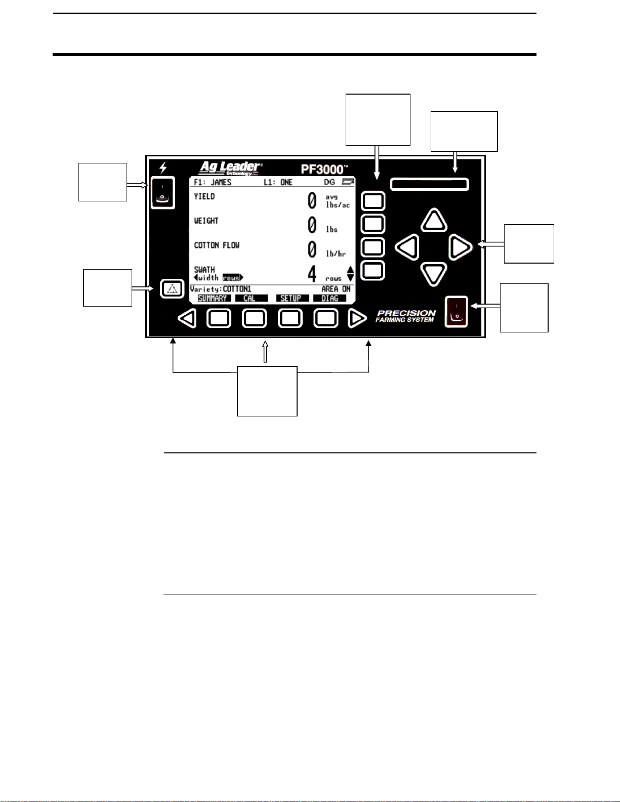
The monitor has "soft" keys which do not have labels on the keys to identify
the function of the key. The labels for the keys will appear on the display
screen next to the key. However, there are four major groups of the keys:
arrow keys, display selection keys, menu key, menu selection keys.
General
March 2002
Page 8
1-4
Switch
PF3000 Cotton Yield Monitor
General
Power
Switch
Menu
Key
Arrow Keys
Ag Leader Technology
Display
Selection
Keys
Menu
Selection
Keys
Figure 1: Front panel of the PF3000
The UP, DOWN, LEFT and RIGHT ARROW keys on the right side of the
keypad are used to select and change a setting. The bottom LEFT and
RIGHT ARROW keys are only used to view more menu or display items.
They are never used to select or change a setting.
On the main operating screen, you may see an up and down arrow symbol
that will be to the right of one of the display lines. This symbol indicates
what item the UP or DOWN ARROW keys will change if pressed.
Memory
Card Slot
Arrow
Keys
Area
Count
March 2002
Page 9

PF3000 Cotton Yield Monitor
1-5
Ag Leader Technology
Display and
Display Selection
Keys
Selection
Box
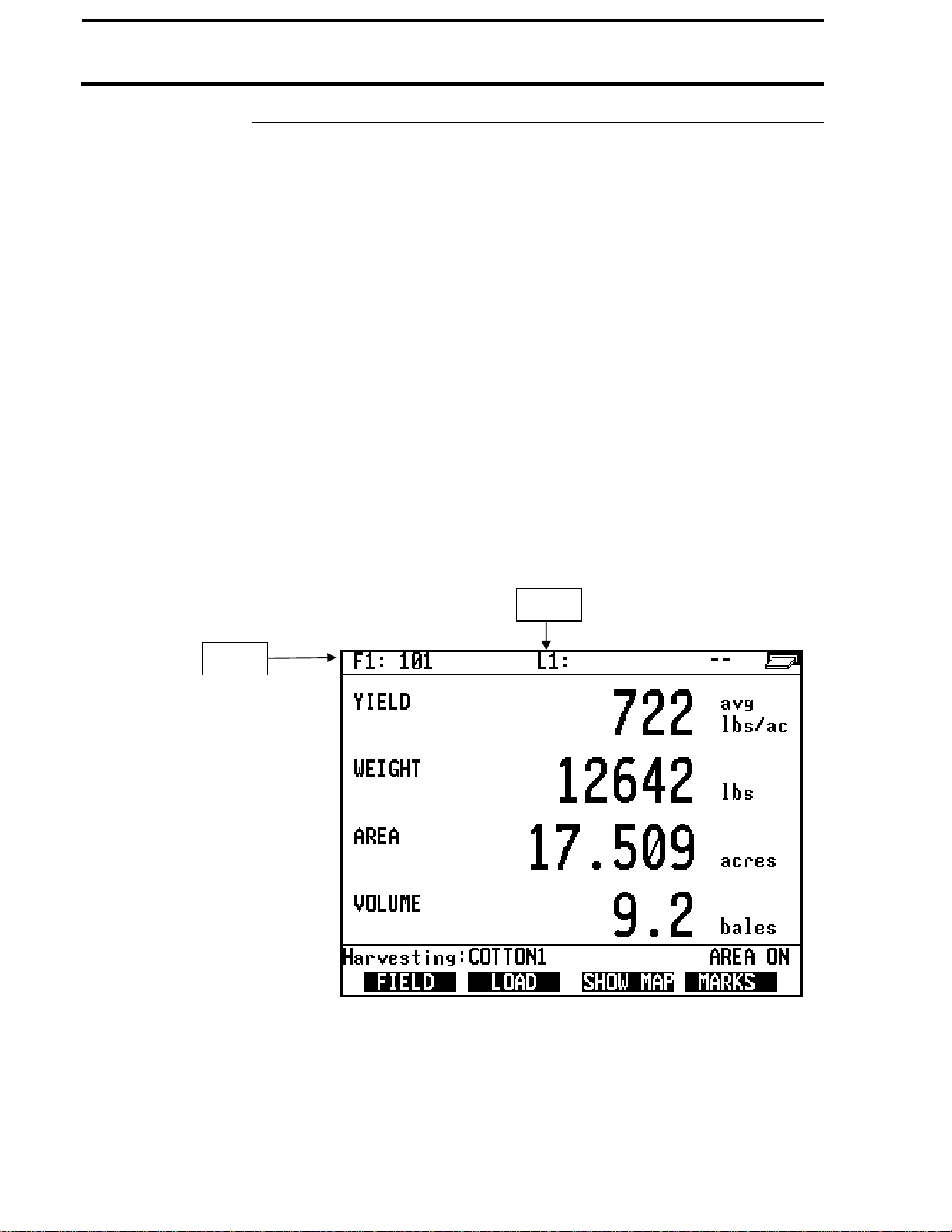
The PF3000 has four display lines for viewing items on the main operating
screen. You can choose which items you see on the display and the position
that the items appear on the display.
To change a display item on a display line you must select the line. The four
display selection keys to the right of the display each select a display line. A
rectangular box surrounds the display line to show that it is selected.
When the display line is selected the four menu items on the bottom change
and show items you can select for display. Press a key below one of the
four display items to put a different display item in place of the selected
display item. There are more than four display items to choose for viewing.
Press the bottom LEFT or RIGHT ARROW keys to scroll to the right or left
and view other display items on the bottom.
Figure 2: Main operating screen
When arrows present,
press bottom arrow keys
to display additional
menu or display items
General
Card
Symbol
Up and
Down
Arrow
Symbol
March 2002
Page 10

1-6
PF3000 Cotton Yield Monitor
General
Menu Key
Menu Selection
Keys
Ag Leader Technology
When some display items (like swath) are selected, an up and down arrow
symbol will appear on the right of the display line. This indicates you can
change the setting of the item with the UP or DOWN ARROW keys. After
you have made the change you must press the key to the right of the display
line to deselect the line.
The MENU key switches the menus on the bottom of the display. There are
two main menus that you can view by pressing the MENU key. They are
shown below.
It is recommended to display the FIELD, LOAD, menu during normal
operation of the monitor, unless you are marking and therefore need to
display marks on the bottom.
Main Menus:
SUMMARY
FIELD
The name above the four menu selection keys on the bottom of the display
will change depending on what you are doing on the monitor.
The bottom RIGHT and LEFT ARROW keys are used to view additional
menu or display items. If you see a right and left arrow symbol on the
display above the bottom RIGHT and LEFT ARROW keys, this indicates
you can press the bottom RIGHT and LEFT ARROW keys to view more
menu or display items. Refer to Figure 2.
LOAD
CAL
SHOW MAP
SETUP
MARKS
DIAG
March 2002
Page 11
PF3000 Cotton Yield Monitor
1-7
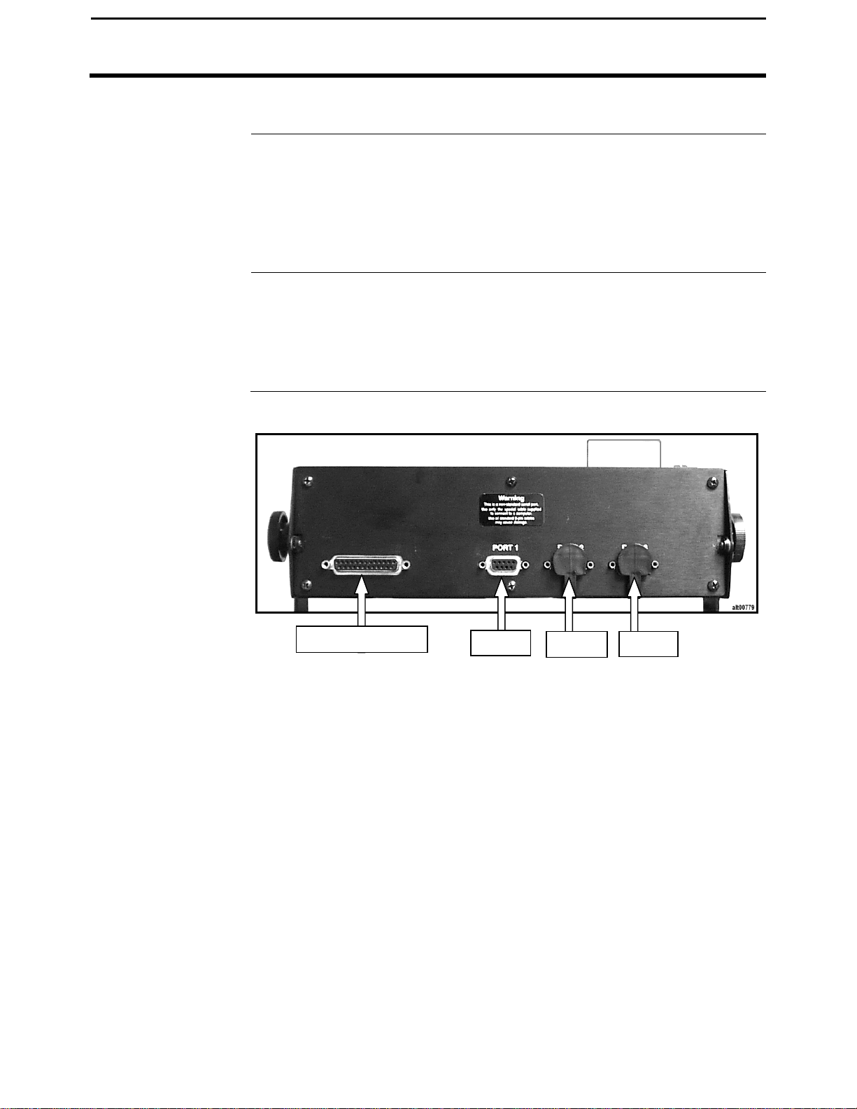
25-Pin Connector
Port 1
Port 2
Port 3
Ag Leader Technology
Area Count Switch
Connectors
The area count switch manually turns area counting on and off. When the
switch is in the up position area is counting. When the switch is in the
down position, area is not counting. The monitor will display either "AREA
ON" or "AREA OFF" on the bottom right corner of the display to indicate
the status of area counting.
The PF3000 has four connectors on the bottom side of the console. The
large 25-pin connector is for power and sensor connections. The three 9-pin
ports (Port 1, Port 2 and Port 3) are for connecting a GPS receiver (Port 1)
and as yet to be determined functions for Ports 2 and 3.
General
Figure 2: PF3000 Connectors
March 2002
Page 12
1-8
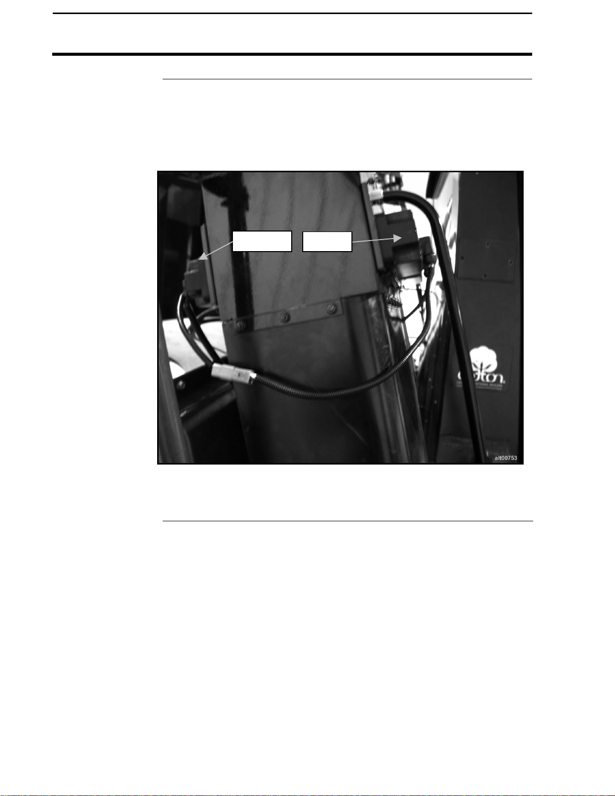
Emitter
Detector
PF3000 Cotton Yield Monitor
General
Flow Sensor
Ag Leader Technology
Below is an example of a flow sensor. On all cotton pickers, the flow
sensor installs on the basket duct. The flow sensor measures the cotton
weight in pounds as the cotton passes between the emitter and detector.
Figure 4: Flow Sensor
March 2002
Page 13

PF3000 Cotton Yield Monitor
1-9
Ag Leader Technology
Header Height
Sensor
Header Sensor
Below is an example of a header height sensor installed underneath a picker
cab. The header height sensor tells the monitor the position of the header so
that when the head is raised on the end rows, the monitor stops counting
area.
General
Figure 5: Header Height Sensor
March 2002
Page 14

Page 15
PF3000 Cotton Yield Monitor
2-1
Ag Leader Technology
Important Notices
Section Contents
Using Power
Supply
The PF3000 must be set up before field operation, but before you begin the
setup procedures, read the following notices:
• The PF3000 is a software upgradeable monitor. Ag Leader Technology
will periodically offer free operating program upgrades to increase the
capabilities of the PF3000. To receive the program upgrade, you
must send in the registration form found at the beginning of the
Operator’s Manual.
• If you plan to make yield maps on your own computer, you will need to
use a mapping program that can process data from the PF3000. Memory
cards can be ordered through your Ag Leader Technology dealer.
This setup section contains instructions for the following items. The
operating modes that the instructions pertain to are also listed.
Item Page
Console Setup 2-3
Vehicle Setup 2-5
Cal Set Setup (see calibration section)
Card Setup 2-10
Swath Setup 2-15
Marker Setup 2-17
Creating, Naming Fields & Loads (1st & 2nd Pick) 2-19
Memory Setup 2-24
Sensor Setup 2-26
The PF3000 console does not need to be in the vehicle to set it up. You can
use the provided power supply (plugs into 120v outlet) to power up the
console inside your home or shop.
Setup Overview
March 2002
Page 16
2-2
PF3000 Cotton Yield Monitor
Setup Overview
Order of Keys
(Harvest Mode)
Ag Leader Technology
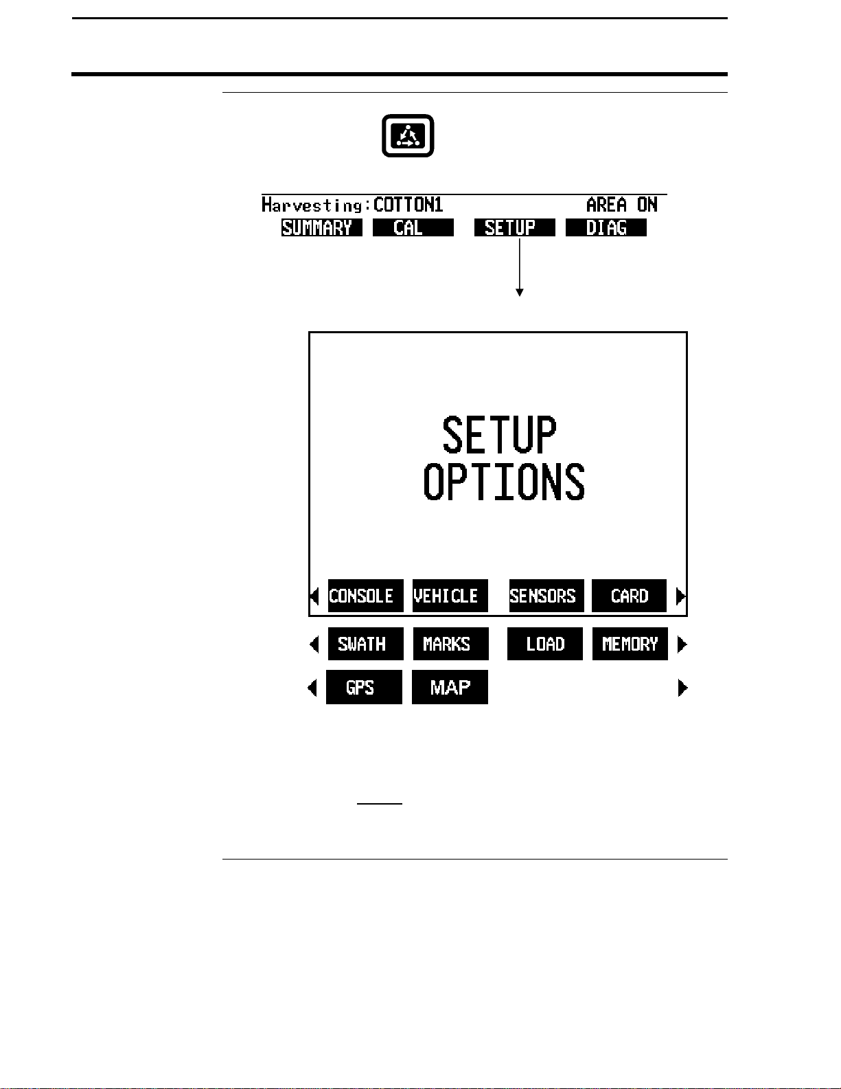
Press the MENU key until you see the following keys on
the display.
Press the SETUP key
to view the following
setup menu items.
NOTE: Instructions for GPS Setup are located in the Add-On GPS
3000/3050/3100 Installation and General Instructions
Press the bottom LEFT or RIGHT ARROW keys to
switch between and view the setup menu items
shown above.
* * *
March 2002
Page 17

PF3000 Cotton Yield Monitor
2-3
Changing a Setting
Ag Leader Technology
Introduction
Console Setup
Screen
The console settings are general settings that apply to all operating modes
and uses of the PF3000.
To view the console setup screen press the:
Example of console setup screen:
Console Setup
MENU key
SETUP key
CONSOLE key
Step Action
1 Use the UP or DOWN ARROW keys to select the item you want
to change. The item is selected when a black filled rectangular
box surrounds the entire line.
2 Press the EDIT key and then use the UP or DOWN ARROW keys
to change the number or setting.
3 Once you have changed a setting press the ACCEPT key. Press
the EXIT key once you have made all the settings.
March 2002
Page 18

PF3000 Cotton Yield Monitor
2-4
Voltage calibration
Field Marke
r
Console Setup
Operating mode
Units of measure
Month/Day/Year
Time
Serial number,
Box calibration,
GPS Check Sum
Ag Leader Technology
At this time, Cotton Harvest and Site Verification is the only operating
mode available with the PF3000 Cotton Yield Monitor System. To use the
PF3000 for grain harvest or app rate, a different operating program is
available.
The units of measurement for the PF3000 Cotton Yield Monitor are
Imperial or Metric.
Use the LEFT or RIGHT ARROW keys to move from month to day to year.
Use the UP or DOWN ARROW keys to change the value. The whole
month, day or year is highlighted and only the last digit increments. Press
LEFT or RIGHT ARROW to set to item to be edited.
12 Hour Clock with AM/PM. The whole hour (2 digits) or minutes value (2
digits is highlighted when editing. AM changes to PM when incrementing
by 12. Press LEFT or RIGHT ARROW to set to item to be edited. If you
are using metric units of measure the 24 hour clock is used.
The serial number, box calibration number and voltage calibration number
can be found on the bottom side of the monitor. These numbers should be
set correctly from the factory.
If you are using a GPS receiver with the PF3000 the GPS Check Sum setting
is used to enable or disable data string error checking.
NOTE: For all Ag Leader receivers (GPS 2000/2100, Add-on GPS
3000/3100), and Trimble 120,122,132 receivers the GPS Check Sum should
be set to ON.
For most other brands of GPS receivers the GPS Check Sum should also be
set to ON. If you can not get a "D" and "G", though, set this setting to OFF.
If you are… Select
Marking field points with the PF3000’s internal
INTERNAL
marker selection keys.
Marking field points with an external Ag Leader
EXTERNAL
Field Marker.
* * *
March 2002
Page 19
PF3000 Cotton Yield Monitor
2-5
Ag Leader Technology
Introduction
Vehicle Setup
Screen
For each operating mode, there are different items to setup in the vehicle
setting screen. Below are the setup items for the cotton mode. Refer to
your Initial Calibration Sheet to make the correct settings.
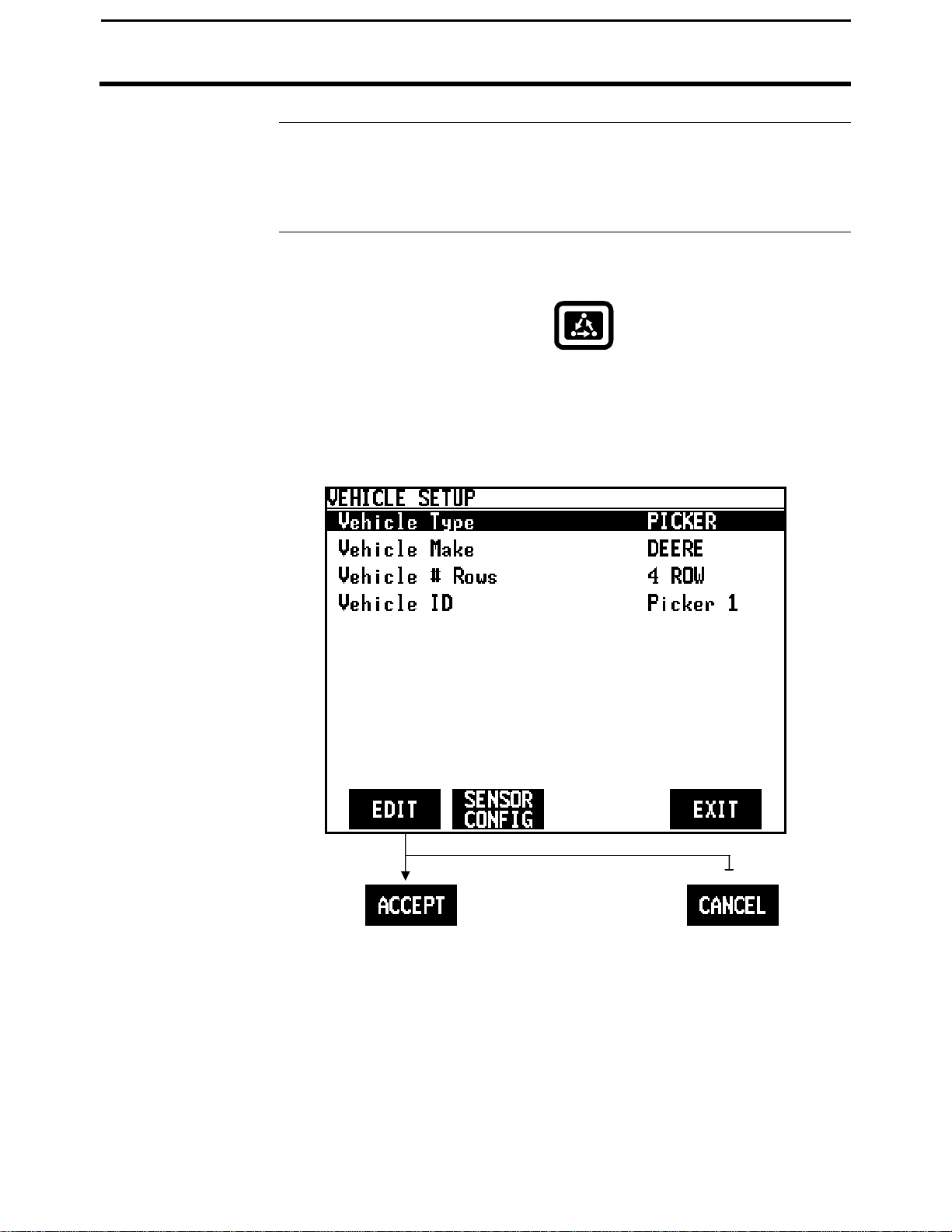
To view the vehicle setup screen press the:
Example of vehicle setup screen:
Vehicle Setup
MENU key
SETUP key
VEHICLE key
March 2002
Page 20
PF3000 Cotton Yield Monitor
2-6
Changing a Setting
Vehicle Setup
Vehicle Type
Vehicle Make
Vehicle Nuber of
rows
Vehicle I.D.
Step Action
1 Use the UP or DOWN ARROW keys to select the item you want
to change. The item is selected when a black filled rectangular
box surrounds the entire line.
2 Press the EDIT key and then use the UP or DOWN ARROW keys
to change the number or setting.
3 Once you have changed a setting press the ACCEPT key. Press
the EXIT key once you have made all the settings.
This is currently set as picker.
At this time Deere and CASE-IH are the only selections. CASE-IH is the
default setting.
Set the number of picking units that are on your picker. The number of rows
must be set before completing Swath Setup later in this section. The
settings range from 2 to 6 rows.
Enter a name for the vehicle. The name of a driver or simply a unique name
or number for each machine is recommended.
Ag Leader Technology
March 2002
Page 21
PF3000 Cotton Yield Monitor
2-7
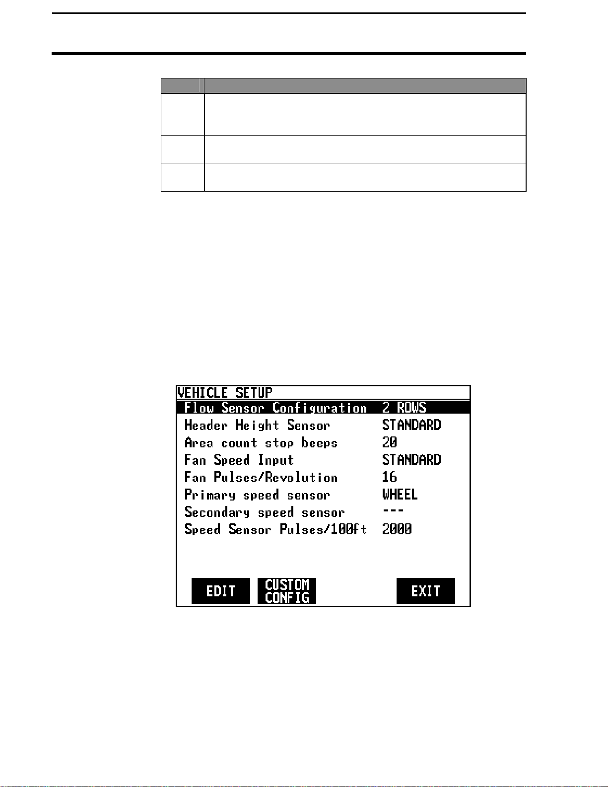
Set the number of flow sensors installed on the picker. 2 rows is the default.
Beeps
Ag Leader Technology
Flow Sensor
Configuration
Header Height
Area Count Stop
Fan
Pulses/Revolutions
Primary and
Secondary Speed
Sensor
Speed sensor pulses
/ 100 ft.
All rows will assign the appropriate number of sensors for each row. Cotton
strippers are fixed at 3 sets of sensors regardless of the number of rows
harvested.
Set as either STANDARD or OPTIONAL. Standard is the only header
height sensor available at this time.
The range for setting area count is 1 through 100. The default setting is 20.
This is the number of times the monitor beeps when the head is raised.
Sets the number of pulses per revolution to correctly display fan speed on
the PF3000. The default setting for CASE-IH pickers is 30. For John Deere
pickers 16.
The monitor has four different primary speed settings. They are listed
below.
Ground Speed Sensor Primary Speed Sensor
Speed sensor on transmission WHEEL
Speed sensor on tracks TRACK
Radar gun RADAR
GPS receiver (must be rated for accurate
ground speed: GPS2000/2100, Add-On
GPS3000/3100 and Trimble AgGPS receivers)
If you choose GPS as your primary speed sensor, you need to set the
secondary speed sensor to WHEEL, TRACK, or RADAR. If the GPS signal
is lost, the monitor will use the secondary speed sensor. If you do not
choose GPS as your primary speed sensor you can not set the secondary
speed sensor.
It is not recommended that you change this setting. This number is the
distance calibration number that is set when you perform a distance
calibration for WHEEL, TRACK or RADAR. Refer to the calibrating
distance instructions in the Calibration section. You must calibrate distance
for a WHEEL, TRACK or RADAR setting for accurate ground speed.
Vehicle Setup
GPS
March 2002
Page 22

PF3000 Cotton Yield Monitor
2-8
Vehicle Setup
Custom
Configuration
Ag Leader Technology
NOTE: If you want to use a radar gun, contact an Ag Leader Technology
dealer and purchase a special adapter cable for your radar gun.
This screen allows you to define where the sensors are located. On the
Vehicle Setup screen you defined the make, configuration and the number
of rows sensed. The CUSTOM configuration is defined on this screen.
The number of rows displayed on this screen is defined by the Picker
Configuration. The choices are limited by the Picker Make. Options will
vary between picker and cotton strippers.
The Picker Configuration & Flow Sensor Configuration define the default
sensor locations. For example:
4-Row Picker / 2 Rows: Row 1 and 4 are defined as FRONT/REAR.
5-Row Picker / 2 Rows: Row 1 and 5 are defined as FRONT/REAR.
6 Row Picker / 2 Rows: Row 2 and 5 are defined as FRONT/REAR.
2, 4, 5, 6 Row Picker / All Rows: All Rows are defined as FRONT/REAR.
NOTE: For CASE-IH Pickers the choices are NONE,
FRONT/REAR and FRONT ONLY. For Deere Pickers the choices
are NONE and INSTALLED.
March 2002
Page 23

PF3000 Cotton Yield Monitor
2-9
Ag Leader Technology
Vehicle Setup
* * *
March 2002
Page 24

2-10
PF3000 Cotton Yield Monitor
Card Setup
Introduction
Card Setup Screen
Ag Leader Technology
If you are using a GPS receiver, all the GPS data must be logged to a
memory card. If you are not using a GPS receiver, you do not need a card.
The memory card must be formatted with a DOS format. Cards rarely need
to be formatted since they are usually DOS formatted before they are
shipped. If formatting is required, format the card in your PC before using.
If you will be using multiple PF3000 monitors, label the memory cards to
identify them to a specific monitor. This will help prevent confusion when
you download the card information to your PC.
IMPORTANT: You must copy memory to every log file you
create and log to before you read the card into your computer.
This is automatically performed on startup and shutdown.
To view the card setup screen press the:
MENU key
SETUP key
CARD key
Example of card setup screens:
March 2002
Page 25

PF3000 Cotton Yield Monitor
2-11
Changing a Setting
Ag Leader Technology
Card Setup
Step Action
1 Use the UP or DOWN ARROW keys to select the item you want
to change. The item is selected when a black filled rectangular
box surrounds the entire line.
2 Press the EDIT key and then use the UP or DOWN ARROW keys
to change the number or setting.
3 Once you have changed a setting press the ACCEPT key. Press
the EXIT key once you have made all the settings.
Logging Device
If you are using a GPS receiver with the PF3000 you must use a memory
card to save the instantaneous GPS data.
If you... Select
Logging Interval
This setting determines how often the GPS information is saved to the
Do not have a GPS receiver. NONE
Do have a GPS receiver. MEMORY CARD
memory card. It also affects how large an area each GPS record will
represent on a map and how many logging hours are available before the
memory card becomes full.
There are three possible settings for the logging interval. 1, 2 or 3 seconds
The recommended setting is either two or three seconds.
3 mph
5 mph
20 M SANDISK ATA
1 sec 2 sec 3 sec
4.4 8.8 13.2
7.3 14.6 21.9
Approximate Logging Hours Until Card is Full
1 sec 2 sec 3 sec
25.8 47.2 65.2
Distance Traveled (ft)
Flash Card
32 M SANDISK ATA
41.2 75.5 104.3
Flash Card
NOTE: The logging hours available can vary from the numbers shown
above due to a variety of operating conditions. The number of fields
and loads, the number of separate files on the card and the number of
times the memory is copied to the card all affect the log file size.
.
March 2002
Page 26

2-12
Log File Format
PF3000 Cotton Yield Monitor
Card Setup
Log File
Logging Shutoff
Delay
Ag Leader Technology
The PF3000 requires a log file to store data on a memory card. The log file
will always have a ".PFL" extension and be named with the date the file was
created. Example: 98081502.PFL, second file created on 08/15/98.
If you have multiple PF3000 monitors, the monitors will create the same log
file name for each day’s harvest. Before downloading the card information,
create a separate file directory on your PC for each monitor and download
card data to these directories.
IMPORTANT: You must copy memory to every log file you create and
log to before you remove the card from your monitor. If you power the
monitor down before you remove the card, this will be done
automatically.
Type of Card Log file criteria
SANDISK ATA
FLASH card
A new log file must be created for each day. Can not add
to an old log file after a new file has been created. Can
store multiple log files on one card.
In order to log instantaneous GPS data or copy field and load data to a
memory card, a log file must be selected. Every time you turn on the monitor,
the monitor will prompt you to select or create a log file. Refer to the steps
below to select or create a log file after the monitor has been turned on.
Step Action
1 Select Log File and press the EDIT key.
2 Select a log file or press CREATE FILE key to create a new log file.
3 With the desired file selected, press the ACCEPT key.
NOTE: After you read all the log files on your card into your
computer (and make backup copies of files), it is recommended to
erase the log file(s) on the card.
For the PF3000 Cotton Yield Monitor, this option is not selectable.
The shutoff delay range is from 0 to 30 seconds. The default setting is 3
seconds.
March 2002
Page 27

PF3000 Cotton Yield Monitor
2-13
Ag Leader Technology
Copying Data to
Log File
Restoring from
File
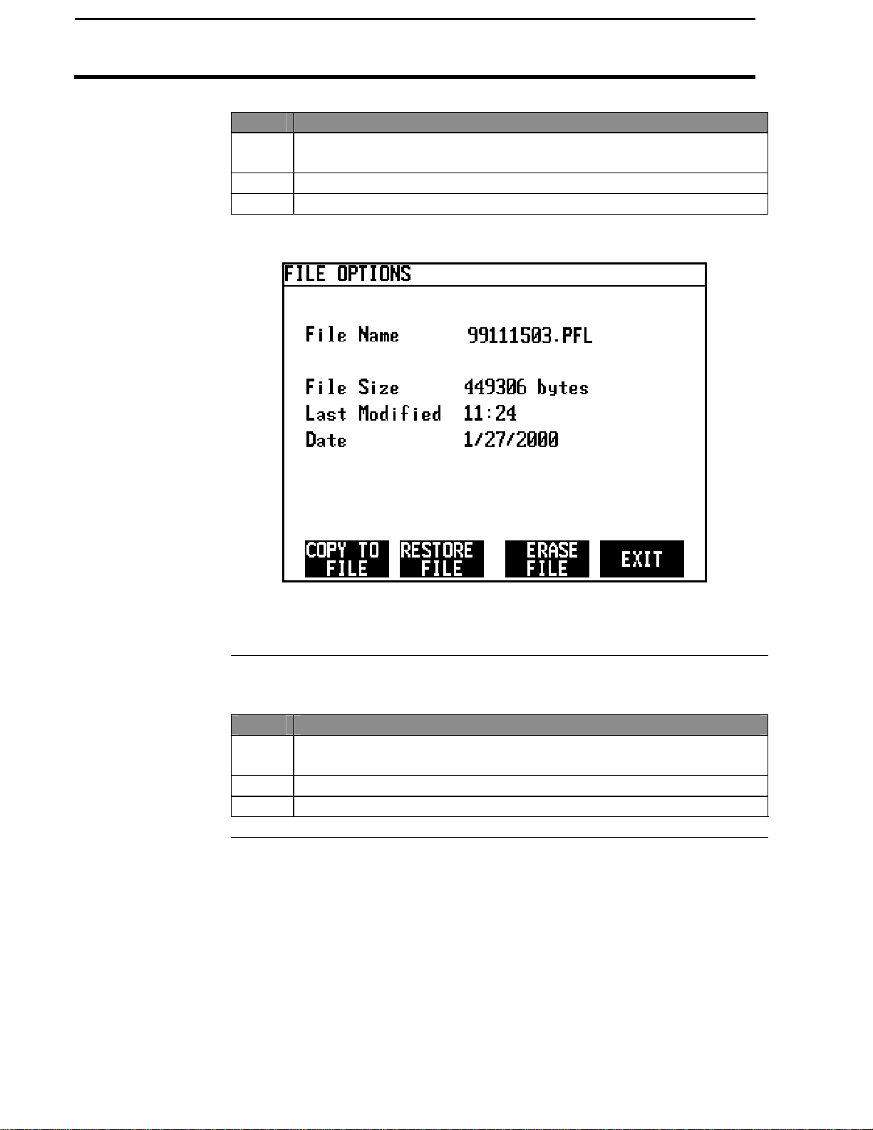
To copy memory to log files that are not set as the current log file, press the
SHOW FILES key and select one of the log files. Press the FILE OPTIONS
key and press the COPY TO FILE key. At the card setup screen, press the
COPY TO CARD key to copy memory to the file set as the log file (this is the
same copy to card function that you are prompted to do during shut down).
You can restore field and load data into the monitor’s memory from a log file
on a memory card..
IMPORTANT: Before you remove the memory card from the
monitor, you must copy memory to every log file that you have
logged to, otherwise your data could be lost. Every time you turn
off the monitor, it will automatically copy memory to card (this
copies memory only to the file set as the log file).
IMPORTANT: It is dangerous to restore memory from a card
because the current data in the monitor will be replaced with the
data on card.
Card Setup
March 2002
Page 28
2-14
PF3000 Cotton Yield Monitor
Card Setup
Ag Leader Technology
Step Action
1 Press the SHOW ALL FILES key. Select the log file and press the
FILE OPTIONS key. Press the RESTORE FILE key.
Erasing File
2 Press the RESTORE key again if you really want to restore the data.
3 Press the EXIT key once you are finished.
You can erase individual log files from a memory card
Step Action
1 Press the SHOW ALL FILES key. Select the log file and press the
FILE OPTIONS key. Press ERASE FILE key.
2 Press the ERASE key again if you really want to erase the file.
3 Press the EXIT key once you are finished.
* * *
March 2002
Page 29

PF3000 Cotton Yield Monitor
2-15
The swath setup screen is used to set the permanent, full swath of your head.
Swath Setup
Screen
Ag Leader Technology
Introduction
Do not adjust the swath setting on this screen when you encounter a partial
swath while harvesting. Refer to the Swath Setting instructions in
Operation Section and select swath as a display item and set a partial swath.
To view the swath setup screen press the:
Example of swath setup screen:
NOTE: Ensure you have set the number of rows for your cotton
picker on the Picker Configuration line of the Vehicle Setup screen
before completing Swath Setup.
Swath Setup
MENU key
SETUP key
Bottom RIGHT ARROW key
SWATH key
March 2002
Page 30

2-16
Center
PF3000 Cotton Yield Monitor
Swath Setup
Ag Leader Technology
Changing a Setting Step Action
1 Use the UP or DOWN ARROW keys to select type of spacing to
be set.
2 Press the EDIT key to change the spacing. Use the UP or DOWN
ARROW keys to change the number. Press the ACCEPT key after
you have changed the number.
Full Swath
3 Press the EXIT key once you have made all the settings.
Adjustable in 1 inch increments. The range of settings is from 30 to 500
inches. Set the full swath in the monitor to the full swath of your header.
For broadcast headers it is advisable to set the swath to 6” to 12” less than
the actual swath width of the header because you can rarely maintain a full
swath while harvesting. In some cases, the number of rows the header can
harvest will exceed the limit of the monitor. If this happens, the full swath
is what you should be concerned with. It does not matter if the number of
rows or the width of each row in the monitor does not exactly match your
true situation.
Row to Row
Spacing
Selecting this option changes the line selected to only highlighting the
spacing value. The UP or DOWN ARROW keys will adjust the value by
whole number increments. When swath is edited, all row spacings become
equal to the full swath divided by the number of rows. The default is 40
inches. The limits are from 10 to 100.
Row 1 to Vehicle
Adjustable in 1 inch increments. Limits are from 0 to full swath value.
This accounts for offset headers.
Refer to the Swath Setting instructions in the Operation Section for more
information about partial swath.
* * *
March 2002
Page 31
PF3000 Cotton Yield Monitor
2-17
Marker Setup
Ag Leader Technology
Introduction
Screen
If you are using an external Field Marker ignore the instructions below. The
marker setup screen is only used for making settings for the Internal marker
selection keys. You may make up to 4 marks on the internal setting.
IMPORTANT:
If you are using the external field marker, make sure that under the
CONSOLE key you set Field Marker to EXTERNAL.
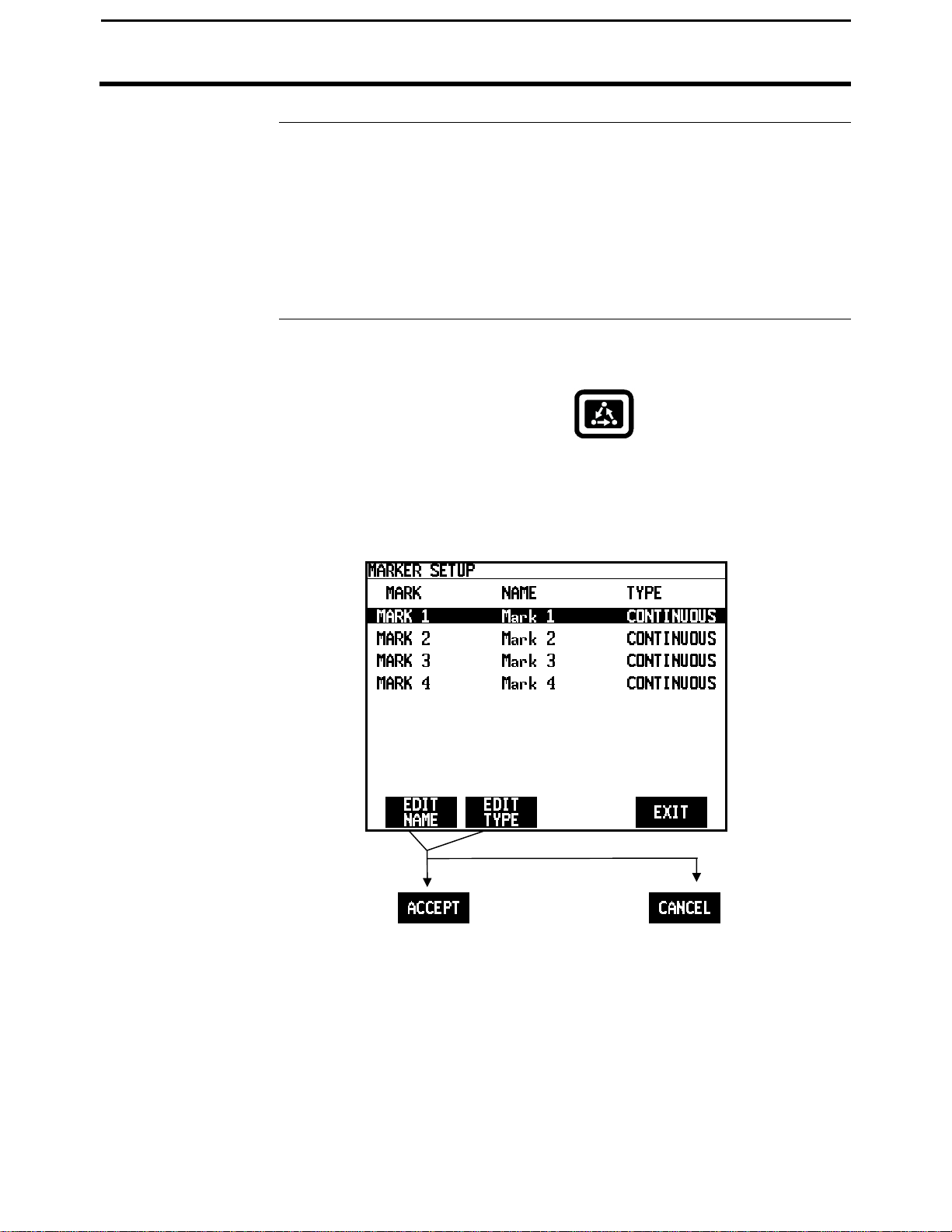
To view the marker setup screen press the:
Example of marker setup screen:
Marker Setup
MENU key
SETUP key
BOTTOM right arrow key
MARKS key
March 2002
Page 32
PF3000 Cotton Yield Monitor
2-18
Changing a Setting
Marker Setup
Step Action
1 Use the UP or DOWN ARROW keys to select the mark. The mark
is selected when a black filled rectangular box surrounds the entire
line.
2 Press the EDIT NAME key to rename an existing mark. Use the
UP or DOWN ARROW keys to change a character in the name.
Use the LEFT or RIGHT ARROW keys to move the cursor over
another character within the name. Press the ACCEPT key after
you have changed the name.
3 Press the EDIT TYPE key to set the mark for continuous or spot
marking. Use the UP or DOWN ARROW keys to change the
setting. Press the ACCEPT key after you have changed the setting.
4 Press the EXIT key once you have made all the settings.
Continuous marking
Set the marking type to continuous if the item in the field you are marking
requires you to make several marks in a row (for example: marking large
weed patches or tile lines).
When you press a mark key that is set for continuous marking, the mark will
remain on until you press the mark key again to turn off the mark.
Spot marking
Set the marking type to spot if the item in the field you are marking requires
just one mark (for example: marking a rock or tile hole).
When you press a mark key that is set for spot marking, the mark will
remain on only for a few seconds and then will automatically go off.
* * *
Ag Leader Technology
March 2002
Page 33

PF3000 Cotton Yield Monitor
2-19
Ag Leader Technology
Recommendations
All the information recorded by the PF3000 must be recorded in a field and
load. The field and load that the monitor is set on is located on the top line
of the display on the main operating screen.
Fields
You should at least create all the fields and name them before you begin to
use the PF3000. You should choose field names that you can use year after
year.
If you are unable to properly set-up your monitor before harvest, you may
create fields as you harvest. If there are errors made by the operator in that
the fields did not get changed at the proper time or did nor get changed at
all, you may use a sort feature in the SMS software that allows you to
automatically sort the data into the correct field. This is only possible if you
have created boundaries for each of the fields.
Second Pick Option: The second pick feature is available so if you second
pick a field, you can separate the data from the first pick which allows for
further analysis. The second pick feature also allows there to be one
calibration set for all second pick fields and loads.
Loads
It also recommended to create and name loads within fields before you use
the PF3000. Each operating mode of the PF3000 will have its own set of
loads for each field.
Definition:
Load: A load is used to subdivide a field into smaller sections. The
monitor load is not associated with the picker basket, wagon, or
truck load.
Creating, Naming Fields, & Loads
March 2002
Page 34
2-20
Field
PF3000 Cotton Yield Monitor
Creating, Naming Fields, & Loads
Creating and
Naming Fields
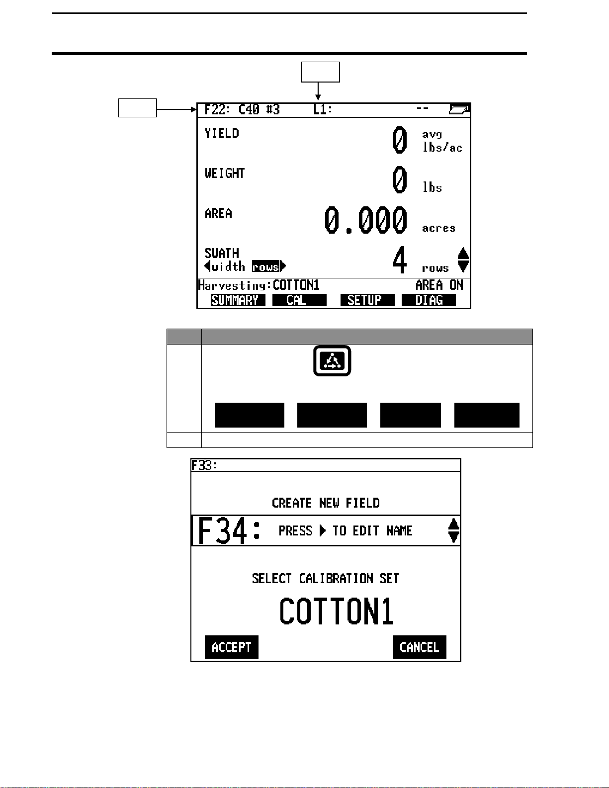
Step Action
1
Press the MENU key until the following is displayed on
the bottom of the display.
FIELD
2 Press the FIELD key twice to view the screen below.
Load
Ag Leader Technology
LOAD
SHOW MAP
MARKS
March 2002
Page 35
PF3000 Cotton Yield Monitor
2-21
Ag Leader Technology
Step Action
3
Naming Field
With the line displaying the field number selected (rectangular box
surrounds line), press the RIGHT ARROW key to move the cursor to
the right to enter a name. Use the UP or DOWN ARROW keys to scroll
through letters, numbers and other characters. After you have set the
character, move the cursor to the right by pressing the RIGHT ARROW
key and set a new character. You can enter up to a 10-character name.
Press the ACCEPT key once you have entered a name.
4
Creating Fields
Press the UP ARROW key to scroll through all the fields. Once you
scroll past the last field, "Create New Field" will be displayed. Name
the field and set the variety then with "Create New Field" displayed
above the field number press the ACCEPT key to create the new field.
5 When creating fields you have the option to change the calibration set.
You would want to do this if you know you will calibrate this field (or
set of data) different from other fields (or sets of data). Refer to the
calibration section for further details. Field calibration sets can be
modified at a later date as well.
6 Repeat Step 5 and create and name all your fields.
Creating, Naming Fields & Loads
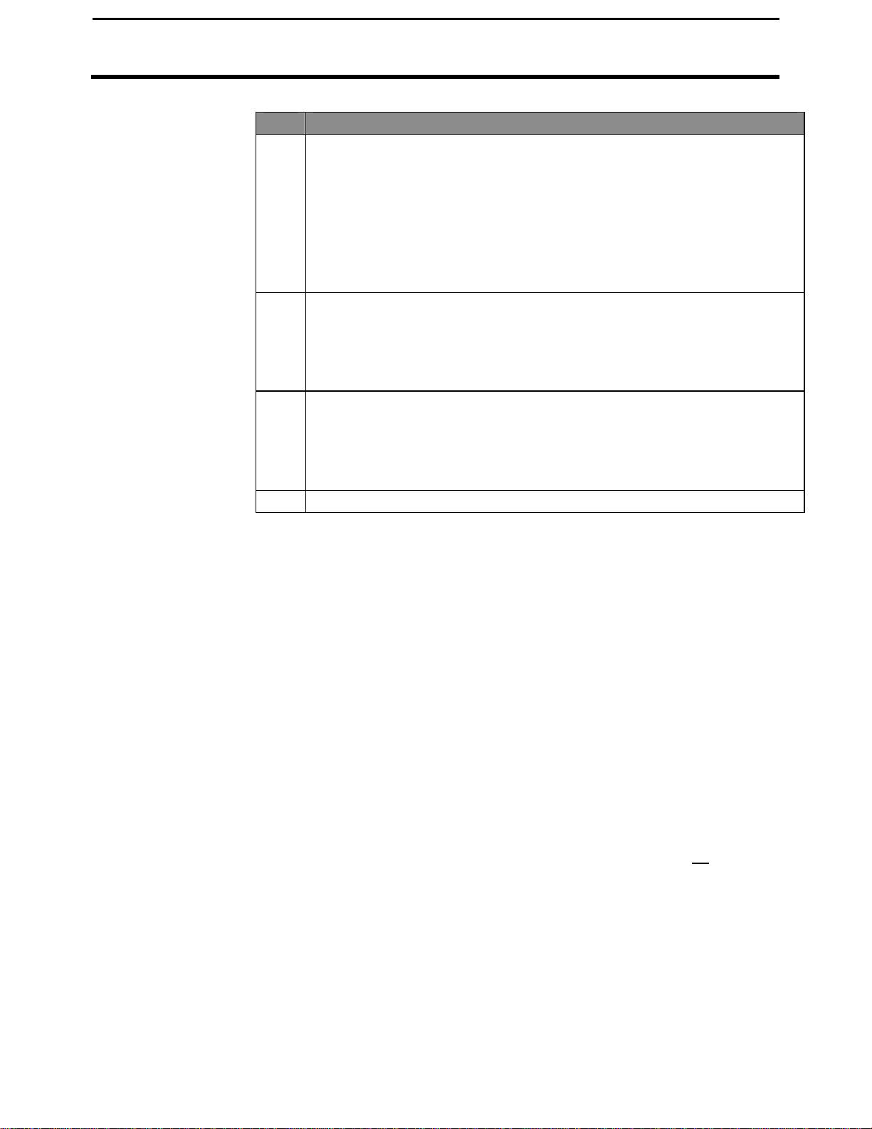
Changing to Second
Pick:
The second pick option is available so first and second picking can be
separated and calibrated differently. In addition, SMS mapping software
allows you to do analysis of each picking or merge the two together. Due to
the extreme difference in harvesting and yield conditions from first and
second pick, it is required to calibrate the second pick separate from the first
pick.
At the change field screen indicated below, the active picking indicates first
pick or second pick. The field below has already been toggled to the second
pick option. Select the item by pressing the key to the right of the item. A
rectangular box will be drawn around the item, indicating it is selected. Use
the arrow keys at the right to toggle the options. Press accept after the
second pick option has been selected. You will be required to change the
second pick instance for each field you wish to second pick.
If this is the first second pick field and a calibration set has not been created,
a new calibration set will automatically be created to be used by all second
pick fields. Refer to the calibration section for further details on calibration.
March 2002
Page 36
2-22
MAP
PF3000 Cotton Yield Monitor
Creating, Naming Fields, & Loads
Creating and
Naming Loads
Step Action
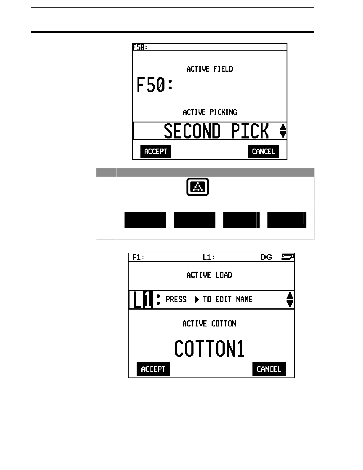
1
Press the MENU key until the following is displayed on
the bottom of the display.
FIELD
2 Press the LOAD key twice to view the screen below.
Ag Leader Technology
LOAD
SHOW
MARKS
March 2002
Page 37
PF3000 Cotton Yield Monitor
2-23
Ag Leader Technology
Step Action
3
Changing Fields
and Loads
Note: Refer to Load Setup to change variety, product or site type for an
existing load.
Changing Field
Press the FIELD key twice to display current field. Press the UP or DOWN
ARROW keys to scroll through the fields. Press the ACCEPT key to
change to the different field.
Changing Load
Press the LOAD key twice to display the current load. Press the UP or
DOWN ARROW keys to scroll through the loads. Press the ACCEPT key
to change to the different load.
Naming Load
With the line displaying the load number selected (rectangular box
surrounds line), press the RIGHT ARROW key to move the cursor to
the right to enter a name. Use the UP or DOWN ARROW keys to
scroll through letters, numbers and other characters. After you have
set the character, move the cursor to the right by pressing the RIGHT
ARROW key and set a new character. You can enter up to an 10character name. Press the ACCEPT key once you have entered a
name.
4 When creating loads you have the option to change the calibration set.
You would want to do this if you know you will calibrate this load (or
set of data) different from other loads (or sets of data). Refer to the
calibration section for further details. A Load's calibration sets can be
modified at a later date.
Step Action
5
Creating Loads
Press the UP ARROW key to scroll through all the loads in the field
for the variety. Once you scroll past the last load, "Create New
Load" will be displayed above the load number and name. Name the
load and set the variety, then with "Create New Load" displayed
above the load number press the ACCEPT key to create the new
load.
6 Repeat step 4 and create and name all your loads.
Creating, Naming Fields & Loads
* * *
March 2002
Page 38

PF3000 Cotton Yield Monitor
2-24
Memory Setup
Introduction
Memory Screen
Ag Leader Technology
The PF3000 has its own internal memory which stores all the field and load
summary data and setup and calibration settings. The internal memory does
not store any GPS data. All GPS data must be logged to a memory card.
To view the memory screen press the:
MENU key
SETUP key
bottom RIGHT ARROW key
MEMORY key
Example of memory screen:
March 2002
Page 39

PF3000 Cotton Yield Monitor
2-25
Card
Ag Leader Technology
Available Memory
Clear Load
Erase Memory
Restoring Data
from a Memory
The monitor does not have a pre-determined number of fields and loads that
it can store. It is only limited by memory. Instead, you should look at the %
memory used to get a relative idea of how many more fields and loads you
can create.
If you want to clear one load or all loads in a field, press CLEAR LOADS
key. Press EDIT key use the UP or DOWN ARROW to select the field
where loads are to be cleared and press ACCEPT key. Scroll down to
LOAD and press EDIT key use the UP or DOWN ARROW key to highlight
a specific load from a field and press ACCEPT key. Press the CLEAR
LOAD key to remove a specific load. The next screen will advise you to
press ACCEPT key to clear the load or CANCEL to abort. To remove all
loads from a field press CLEAR ALL key. The next screen will advise you
to press ACCEPT to clear all loads or CANCEL to abort.
If you want to clear all the setup, calibration and field and load data in the
monitor press the ERASE MEMORY key. The monitor will warn you that
you will lose all the data. Press the ACCEPT key to remove all the data.
You should normally only clear all the data at the beginning of the season.
You can restore field and load data from a memory card. The field and load
data can be from another PF3000 Cotton Yield Monitor or PF3000 Pro
Cotton Monitor. Refer to the card setup instructions in the setup section.
Memory Setup
* * *
March 2002
Page 40
PF3000 Yield Monitor
2-26
Sensor Setup
Introduction
Ag Leader Technology
The flow sensor setup screen will allow you to set the sensitivity of the flow
sensor alarms. The sensor alarms warn you that one or more flow sensors
are not operating correctly and no yield data can be obtained from that
sensor.
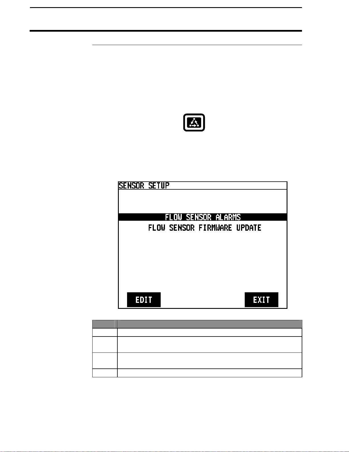
Sensor Screen
To view the sensor setup screen press the:
MENU key
SETUP key
bottom RIGHT ARROW key
SENSOR key
Changing a Setting Step Action
1 Highlight the setting to be changed and press the EDIT key.
2 Press the UP or DOWN ARROW keys to select the setting to be
changed and press the EDIT key.
3 Use the UP or DOWN ARROW keys to change the number value
and press the ACCEPT key.
4 Press the EXIT key when the sensors are set.
March 2002
Page 41

PF3000 Cotton Yield Monitor
2-27
Ag Leader Technology
Choke Sensitivity
Stringer Sensitivity
Low Signal
Threshold
The choke alarm is to alert you when one or more conveyors have
blockages, which could damage your picking drums. The sensitivity
of this alarm can be adjusted from 0 to 100 percent. A sensitivity of
zero means that the alarm is disabled. The zero flow threshold sets a
maximum amount of flow which a conveyor is considered blocked.
The best setting varies widely with yield and the consistency of the
yield throughout the field.
NOTE: If your picker is equipped with a factory-installed choke
alarm system, we recommend using the factory-installed system for
choke alarms.
The stringer alarm is to alert you when one or more conveyors have
strings or ropes of cotton hanging in them which will cause large false
flow readings. The sensitivity of this alarm can be adjusted from 0 to
100 percent. A sensitivity of zero means that the alarm is disabled.
The zero flow threshold sets a minimum amount of flow which a
stringer must cause before the alarm is activated. The recommended
setting is 50 percent, but the best setting varies with field conditions.
The low signal alarm is to alert you to sensors which are too dirty or
are misaligned, causing the yield data to be inaccurate. The threshold
of this alarm can be adjusted from 0 to 60 percent of the full-strength
signal. A threshold of zero means that the alarm is disabled. The
recommended setting is 20 percent.
NOTE: The monitor will still measure yield very accurately even at
signal strengths as low as 20 percent.
Sensor Setup
March 2002
Page 42

PF3000 Cotton Yield Monitor
2-28
Sensor Setup
Zero Flow
Threshold
Flow Sensor
Firmware
Ag Leader Technology
The zero flow threshold affects both the stringer and choke alarms. It
can be adjusted from 0 to 65000, but typical settings are within the
range of 50 to 500. The zero flow threshold sets the amount of flow
which is considered negligible. When driving your picker around, you
may see very small but non-zero flow readings in the Sensor Data
Diagnostics. This threshold should be set larger than the average of
these non-zero readings to avoid false stringer and choke alarm
activations.
To view the flow sensor firmware version, highlight the Flow Sensor
Firmware Update line and press EDIT. Highlight the setting to be
changed and press the EDIT key. Press the UP or DOWN ARROW
keys to select the setting to be changed and press the EDIT key. Use
the UP or DOWN ARROW keys to change the number value and
press the ACCEPT key. Press the EXIT key when the sensors are set.
March 2002
Page 43
PF3000 Cotton Yield Monitor
3-1
Ag Leader Technology
Introduction
Order of Keys
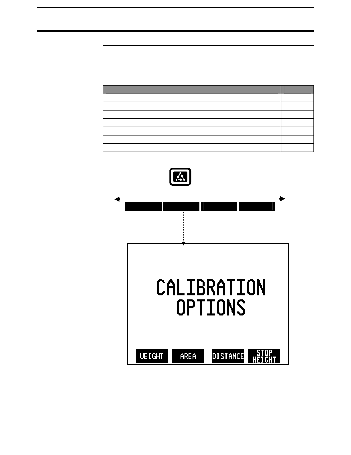
Press the CAL key to view
the following calibration
menu items.
You must calibrate the monitor for it to be accurate.
The calibration section contains instructions for the following items:
Cal Set Setup 3-2
Calibrating Seed Cotton Weight 3-6
Calibrating Area 3-12
Calibrating Distance 3-14
Calibrating Stop Height 3-17
Calibrating Vibration 3-19
Log Sheets (At the end of this section)
Press the MENU key until you see the following on
the display.
SUMMARY CAL SETUP DIAG
Calibration Overview
Item Page
* * *
March 2002
Page 44

PF3000 Cotton Yield Monitor
3-2
Setup Screen
Cal Set Setup
Introduction
Cotton Cal Set
Ag Leader Technology
The Calibration Set is used to create categories of different types of cotton,
different harvest conditions, or any other crop condition unique to your
operation you wish to identify. Your monitor is calibrated based on the
harvested loads of these calibration sets in a field. For example, in the
screen below, Cal Set 1 could be named for a specific type of cotton, or
could be a Cal Set you create during harvest because of changes observed
(post rain, green cotton, etc) in the cotton.
Many users of the PF3000 Cotton Yield Monitor believe it is important to
have the monitor calibrated as accurately as possible at all times.
When the physical characteristics of the cotton change, there could be a shift
in the accuracy of the yield monitor. This means that if the average error
was at 1% (ranging from +3 to –1%) and you moved to a new field and the
error shifts to 15% it would also have the same range 17% to 13%. The
point is within each characteristic change, the yield monitor will be very
consistent. If you goal is to make a yield map showing the variability
relative to other areas within that field, you generally should not need to recalibrate. This is assuming that most physical characteristics of the cotton
are generally similar within a field. In addition, you will have the
opportunity to scale the data in SMS mapping software and correct any
error.
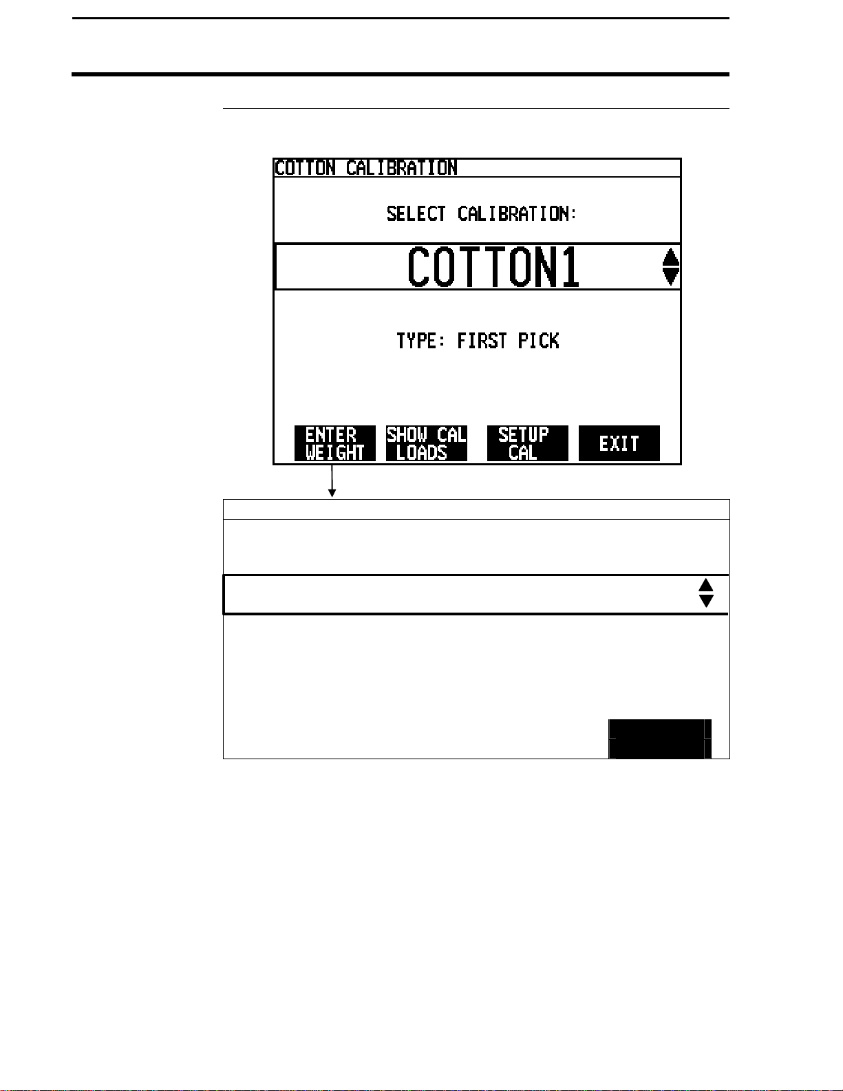
Create a name for an actual variety of cotton planted or for different harvest
conditions. To view the cotton Cal Set setup screen press the:
MENU key
CAL key
WEIGHT key
SETUP CAL key
March 2002
Page 45

PF3000 Cotton Yield Monitor
3-3
Edit Name
Changing a Setting
Ag Leader Technology
Example of cal set setup screen:
Step Action
1 Press EDIT NAME key.
2 Use the UP or DOWN ARROW keys to change the letter. Use the
LEFT or RIGHT ARROW keys to add letters or numbers to the
name.
3 Press the ACCEPT key to complete the name change.
Step Action
1 Press the EDIT SETTINGS key to move to another screen and
change the settings of the default bale size, lint percent, and C
values. Refer to the screen below. See section below for further
details on editing the C values.
2 Press the EDIT key to change the desired item. Use the UP or
DOWN ARROW keys to change the value. Once you have
changed the value press the ACCEPT key.
3 Press the EXIT key once you have made all the settings.
Cal Set Setup
Type indicating
picking instance
March 2002
Page 46

3-4
PF3000 Cotton Yield Monitor
Cal Set Setup
Bale size
Lint percent
Setting Initial C
Numbers
Ag Leader Technology
Example of cal set setup screen:
Bale size can be set between 200 and 800 pounds
Sets the percent of lint per bale. (Lint turn out.)
The three C Numbers, C1, C2 and C3 determine the pounds of cotton the
monitor calculates. At first, the C1, C2 and C3 will be set to default value,
these initial numbers will change and become more accurate after you have
calibrated.
The C values: C1, C2, and C3 represent the following:
March 2002
Page 47

PF3000 Cotton Yield Monitor
3-5
Ag Leader Technology
C1: C1 is the vibration cal number. This number represents some
minimum value that the sensors must output before cotton flow is
calculated. Any signal below this value will not be recorded and cannot
be modified by post calibration. This is the number to be adjusted if a
significant amount of cotton is accumulating when sitting still in
logging mode. (this value should only be adjusted after all other
possible sources are ruled out.) Increase the value to decrease the
influence of vibration.
C2: This value is a scaling value that should never be changed.
C3: The C3 value is the value that will change as a result of performing a
calibration on that cal set. This represents a mathematical value used to
calculate the yield, specific to that cal set.
The C values can be edited as described in the previous steps.
IMPORTANT: Do not change the C numbers after you have
calibrated. If you change the C number after calibration, the
accuracy of the monitor will be effected.
Cal Set Setup
March 2002
Page 48

PF3000 Cotton Yield Monitor
3-6
Calibrating Seed Cotton Weight
Calibration Procedure
Before You Begin
Harvesting
Calibration Loads
Before the monitor will accurately measure weight, you must calibrate the
monitor for seed cotton weight (lbs) before you harvest. You should be able
to calibrate the PF3000 for load weight to an average error of 3 percent to 5
percent.
Although it is recommended, you do not have to calibrate load weight at the
beginning of the season to get accurate results. When you calibrate the
monitor, it will automatically correct weights for all the loads of that cotton
calibration set that were previously harvested.
The monitor calibrates itself on the basis of actual weights you enter into the
monitor. You get the actual load weights by weighing the load on accurate
scales or by obtaining accurate module weights for a load from your gin.
IMPORTANT: For accurate calibration results, you should obtain at
least three calibration loads for each calibration set. Three calibration
loads should reflect the conditions present for the remainder of the
harvesting under that calibration set.
You will get the best results when conditions are the same throughout all
loads harvested within a cotton calibration set. So, it is best to harvest
calibration loads during the afternoon, when moisture is normally at its
lowest point of the day. Moisture variations will have an impact on scale
readings, although it will not in large affect the monitors estimated weight
or maps generated from the yield data. Keep in mind the optical flow
sensors are measuring volume and the scales are measuring weight. The
amount of volume the monitor reads is then matched with the scale weight,
thus calibrating the monitor.
Also, different varieties are more or less fluffy and have different seed mass
so they should not be mixed within a single calibration for maximum
accuracy.
Carefully follow these directions when harvesting your calibration loads.
The following procedure applies to both first and second pick calibrations.
Ag Leader Technology
March 2002
Page 49
PF3000 Cotton Yield Monitor
3-7
Calibration
Ag Leader Technology
Step Action
Seed Cotton
Weight
1 With the cotton picker stopped, the cotton basket completely empty,
and a hauling vehicle empty, set the monitor on a load that does not
have any data. Make sure the load is set on the correct cotton
calibration set.
2 Harvest cotton into the calibration load in the monitor.
NOTE: Harvest 3,000 or more lbs for calibration loads.
3 Unload one or more times into the hauling vehicle, finishing with the
following:
• Cotton basket again empty
• All the cotton from the calibration load on the hauling vehicle
• No cotton from any other picker on the hauling vehicle
4 Immediately change to another load that does not have any data.
5 Weigh the cotton on the hauling vehicle and record the actual load
weight on a log sheet in the back of this section of the manual.
NOTE: If you are using a weigh wagon to weigh the cotton, make
sure the wagon has been calibrated properly.
6 Repeat the above steps and harvest another calibration load. You
can also enter an actual weight and calibrate as you obtain each
actual weight.
To view the weight calibration screen press the:
Calibrating Seed Cotton Weight
Screen
MENU key
CAL key
WEIGHT key
March 2002
Page 50
PF3000 Cotton Yield Monitor
3-8
Procedure
Calibrating Seed Cotton Weight
Calibration
COTTON CALIBRATION
F1: North 80
Ag Leader Technology
L1: Corner E
ACT. WEIGHT:
MEASURED WEIGHT 13000 lb
% ERROR 2.5 %
CLEAR
WEIGHT
13325
EXIT
lb
March 2002
Page 51

PF3000 Cotton Yield Monitor
3-9
LOAD
ACT. WEIGHT
% ERROR
F2: 99B
-80AC
L2: 9352
21789
-0.4 %
L4: 9352
-
0.0 %
L5: -0.8 %
L2: 9281
22400
+0.1 %
WEIGHT
ON/OFF
CAL
Ag Leader Technology
Step Action
1 Use the UP or DOWN ARROW keys to select the cotton calibration
set. Press the ENTER WEIGHT key.
2 Refer to the next screen and change the load (and field if necessary)
to a load for which you want to enter an actual weight. Use the UP
or DOWN ARROW keys to change the field or load, depending on
which is selected.
You must have the field or load line selected (rectangular box
surrounds line) before you can change a field or load. To select
either field or load, press the key to the right of the field or load line.
If the Fields and loads do not appear that you feel should, check the
previous screen to verify you selected the correct cal set.
3 Press the key to right of the "Act. Weight" line to select that line.
4 Use the UP or DOWN ARROW keys and enter the actual weight for
the load. Press the ACCEPT key.
5 Repeat steps 2-4, and enter all the actual weights for all the
calibration loads.
6 Press the EXIT key once you have finished to return to the screen
where you selected the cal set.
7 Press the SHOW CAL LOADS key to view the screen below.
Example of calibration loads screen:
COTTON CALIBRATION : COTTON1
Calibrating Seed Cotton Weight
L3: 9352 +0.4 %
F4: SMITH
L1: 9281 20900 -0.2 %
EDIT
CAL
March 2002
PERFORM
EXIT
Page 52
PF3000 Cotton Yield Monitor
3-10
Calibrating Seed Cotton Weight
Step Action
8 The screen above allows you to include a load in the calibration or
exclude it by “unchecking” it and turning it off.
9 Press the PERFORM CAL key to start the calibration. The monitor
will start calibrating and then it will stop and display "Full
Calibration Complete".
NOTE: The calibration error is the percent difference between the
actual weight and the estimated weight. The maximum error is the
error of the calibration load that has the highest error.
Example:
Actual weight: 10,000 Lbs.
Estimated weight: 10,100 Lbs.
Error: + 1 %
10
Good Calibration Results:
If you have three or more calibration loads, your goal after
completing a calibration should be to achieve an average error of
less than 5 percent and a maximum error of 10 percent
If you have at least three calibration loads, and you find a load with a
high calibration error after completing the calibration, you should
remove the load as a calibration load by pressing the CAL ON/OFF
key. Press the PERFORM CAL key again to restart the calibration.
Once you are satisfied with your calibration results, press the EXIT
key until you return to the main operating screen.
Reasons for high calibration errors on loads
• Cotton calibration set is incorrectly set for the load
• Cotton moisture or density is considerably different between loads.
• Actual pounds value is not correct
• Cotton weighed is not the same amount of cotton that was harvested into
the load (for example: picker basket was not empty before starting the
load or forgot to change loads in the monitor and added more cotton into
the load (in the monitor) after cotton weighed or cotton spilled onto the
ground)
• Installation problem with flow sensor
Ag Leader Technology
March 2002
Page 53

PF3000 Cotton Yield Monitor
3-1
1
Ag Leader Technology
Recalibrating the
Monitor
Periodic Checks
for Accuracy
To improve the monitor’s calibration accuracy, you can add or eliminate a
calibration load and recalibrate the monitor at any time. If you have not
achieved satisfactory calibration results after entering 4 to 5 calibration
loads something is wrong. Refer to the Troubleshooting Section instead of
adding more actual weights.
Throughout the season you should occasionally check the monitor for
calibration accuracy by weighing a monitor load of cotton. If you find the
monitor is not accurate, enter that actual weight into the monitor and
calibrate the monitor again.
It is recommended you verify the calibration when you observe a change in
lint density or seed mass for example; when changing seed varieties or
continuing harvest after a heavy rain.
If a difference is found, you would want to create a new Cal Set, otherwise
previous data will be affected.
Calibrating Seed Cotton Weight
***
March 2002
Page 54
PF3000 Cotton Yield Monitor
3-12
Screen
Calibrating Area
Adjusting Field
Area
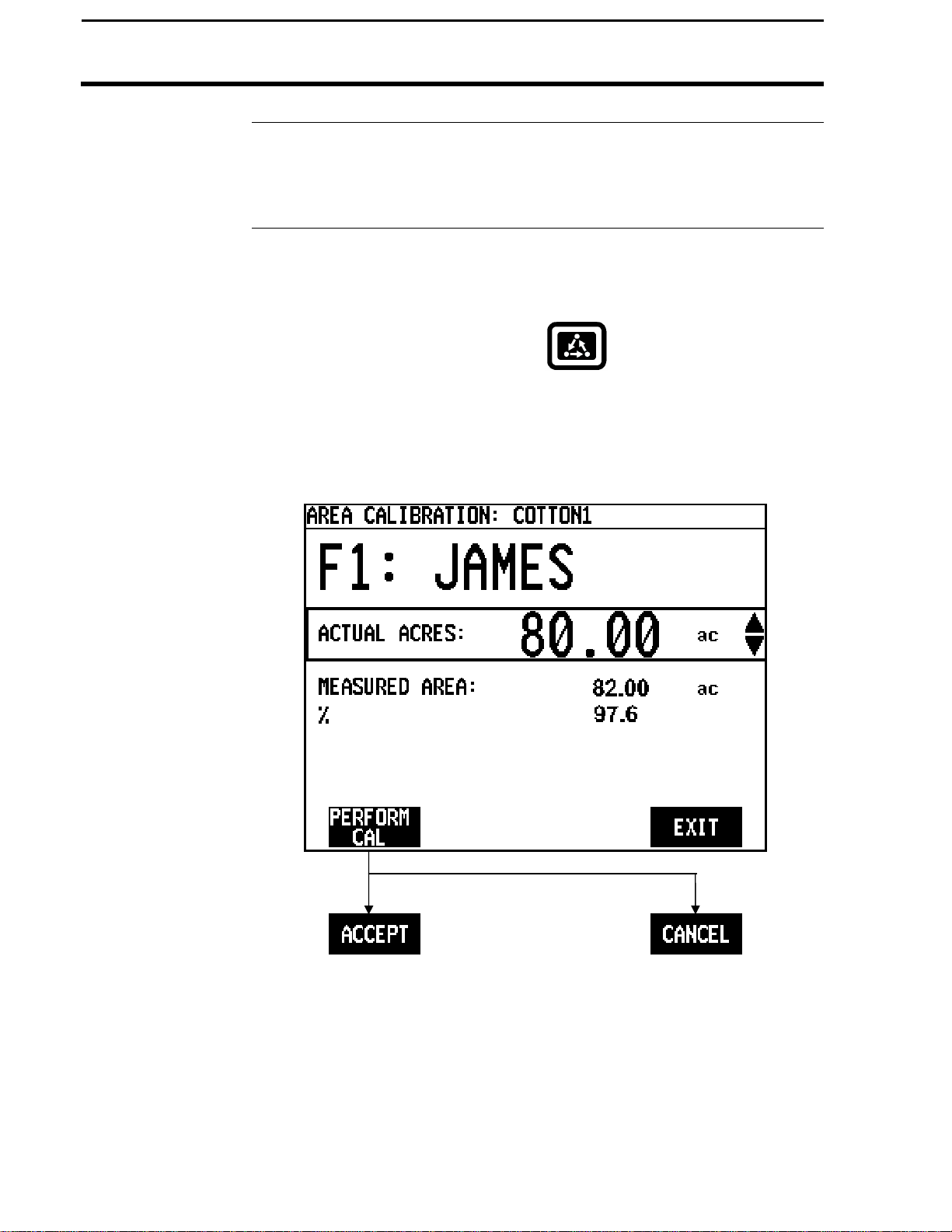
Area Calibration
Ag Leader Technology
If you know the exact field area, you can adjust the monitor field area to the
correct value after you finish the field. Follow these steps to adjust the field
area:
To view the area calibration screen press the:
MENU key
CAL key
AREA key
Example of area calibration screen:
March 2002
Page 55
PF3000 Cotton Yield Monitor
3-13
Calibration
Ag Leader Technology
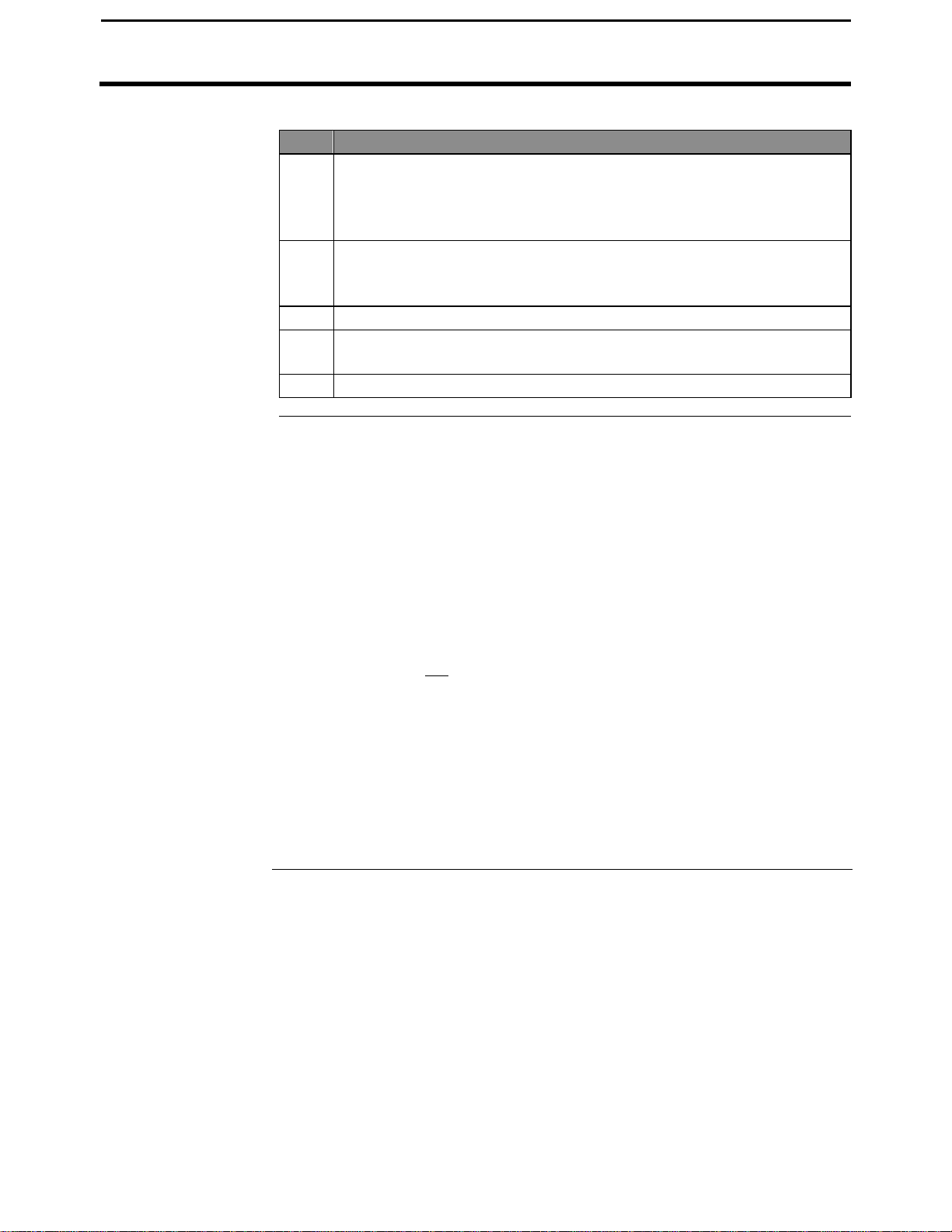
Step Action
Procedure
1 Change the field to a field for which you know the exact area. Select
(rectangular box surrounds line) the field by pressing the key to the
right of the line displaying field. Use the UP or DOWN ARROW
keys to change the field.
2 Select the "Actual Area" line by pressing the key to the right of the
line displaying actual area. Use the UP or DOWN ARROW keys to
set the actual area.
3 Press the PERFORM CAL key. Press the ACCEPT key.
4 Repeat steps 1-4 for all the fields for which you know the actual
area.
5 Press the EXIT key once you have finished.
NOTE:
• The monitor proportionally adjusts all the load areas so that the areas
from all the loads equal the total field area.
• The "Area Cal" number is the actual area divided by the area the
monitor originally counted. When you press the PERFORM CAL key,
the monitor determines the area calibration number and adjusts the
measured area accordingly.
• Usually the monitor slightly over counts area when turning on the ends
due to error in not turning on and off area counting exactly at the start
and end of a pass. It is suggested that you determine an average
percent error in counting area and adjust the field area accordingly,
even if you do not know the exact field area. Typical area calibration
numbers for harvesting row crops are 97-99%.
Calibrating Area
***
March 2002
Page 56
PF3000 Cotton Yield Monitor
3-14
Calibration
Calibrating Distance
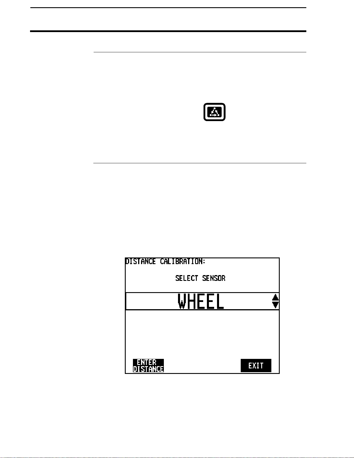
Introduction
Distance
Screen
Choosing Speed
Sensor
You must calibrate distance for a primary or secondary speed setting of
WHEEL, TRACK or RADAR.
To view the distance calibration screen press the:
You must choose the speed sensor you are using for ground speed before
you can calibrate distance. Use the UP or DOWN ARROW key to select
either:
• WHEEL
• TRACK
• RADAR
Press the ENTER DISTANCE key after you have set the ground speed
sensor.
Ag Leader Technology
MENU key
CAL key
DISTANCE key
March 2002
Page 57

PF3000 Cotton Yield Monitor
3-15
Calibrate Distance
Procedure
Ag Leader Technology
Preparing to
Calibration
You must accurately measure a known distance, setting flags or making a
mark at each end of the path.
NOTE:
• Use at least a 200 feet travel path to obtain an accurate calibration.
• For maximum accuracy, calibrate on a ground surface that is similar to
field conditions.
Example of distance calibration screen:
Calibrating Distance
March 2002
Page 58
PF3000 Cotton Yield Monitor
3-16
Calibrating Distance
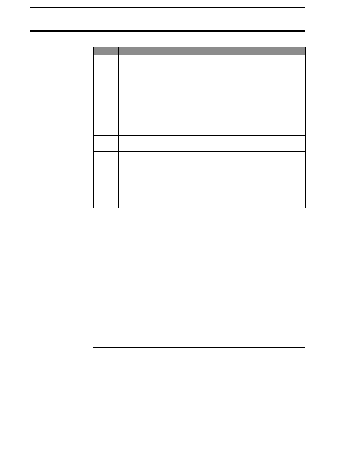
NOTE:
• Upon pressing PERFORM CAL, the monitor automatically adjusts the
• You can manually change the "pulses / 100 ft" number. Select "pulses /
NOTE:
You should record the pulses/100 ft on the log sheet provided. If problems
with the monitor occur, you can enter this value and you will not have to
repeat the Distance Calibration. This value can also be accessed under the
"Vehicle Setup" screen, then "Sensor Config".
Ag Leader Technology
Step Action
1 Use the UP or DOWN ARROW keys to set the actual distance to
the known length of the travel path.
NOTE: The actual distance line must be selected (rectangular box
surrounds line) before you can set the actual distance. Press the
key to the right of the actual distance line to select it if it is not
already selected.
2 Position the vehicle at the beginning of the travel path. Pick a spot
on the vehicle and align it with the mark at the beginning of the
travel path. Press the START TRAVEL key.
3 Drive the length of the path stopping at the end marker and press
the STOP TRAVEL key.
4 Press the PERFORM CAL key to calibrate the distance. Press the
ACCEPT key to accept the calibration.
5 Press the CLEAR DISTANCE key and repeat steps 2-4 and drive
the travel path again to double check the accuracy of the distance
calibration.
6 Press the EXIT key twice after you have finished calibrating
distance.
"pulses / 100 ft" number so that the "Measured Distance" is equal to the
"Actual Distance".
100 ft" by pressing the key to the right of the line. Then use the UP or
DOWN ARROW keys to set the number. Do not change this number
after calibrating.
* * *
March 2002
Page 59
PF3000 Cotton Yield Monitor
3-17
Calibration
Ag Leader Technology
Introduction
Stop Height
Calibration
Screen
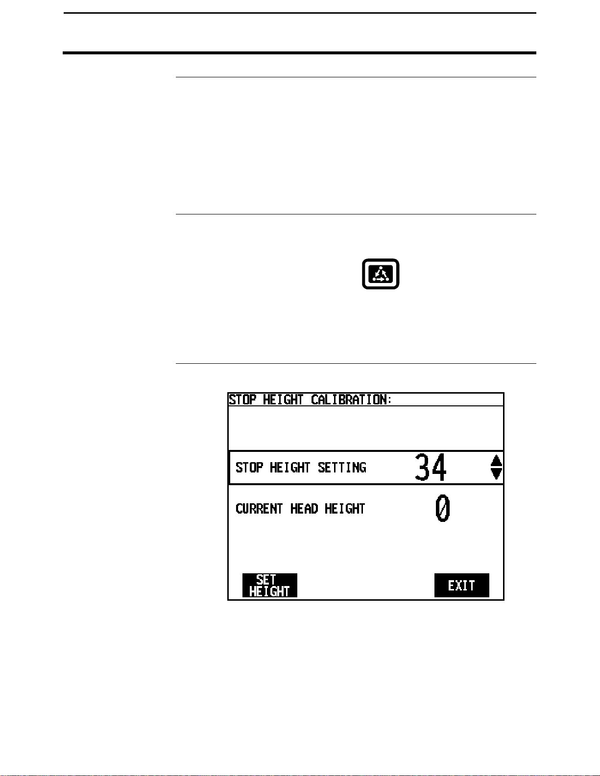
The stop height is the height at which the head must be raised at the end of a
pass to shut off area counting. The stop height number is a reference
number for the monitor to determine the height of the head. It does not
pertain to feet or inches of height.
The stop height number must be set.
You must have the monitor installed in the picker to set the stop height.
To view the stop height calibration screen press the:
Calibrating Stop Height
MENU key
CAL key
STOP HEIGHT key
March 2002
Page 60

PF3000 Cotton Yield Monitor
3-18
Calibrating Stop Height
Step Action
1 Use the UP or DOWN ARROW keys to select stop height setting.
2 Press the SET HEIGHT key.
Step Action
3 Move the picker head to the height at which you want the monitor to
4 Press the SET HEIGHT key. The monitor will automatically set the
5 Press the EXIT key twice to return to the main operating screen.
NOTE: You can manually adjust the stop height number by pressing the
UP or DOWN ARROW key when the screen above is displayed. Adjustment
of the sensor maybe needed to gain more range of motion. Adjust the point
at which the chain attaches to the threaded rod and/or adjust the location
that the chain is attached to the head.
Ag Leader Technology
stop counting area.
stop height setting equal to the current stop height. Press the
ACCEPT key.
* * *
March 2002
Page 61

PF3000 Cotton Yield Monitor
3-19
Ag Leader Technology
Calibrating for
Vibration
C Numbers
The vibration calibration is not automated at this time. If you suspect that
vibration is causing false cotton flow, call Ag Leader Technology Technical
Support at 515-232-5363.
Refer to the previous section on “Calibrating Seed Cotton Weight” where the
C Values are discussed.
The three C Numbers, C1, C2 and C3 determine the pounds that the monitor
calculates. You can display the C numbers by pressing the SET UP CAL
then EDIT SETTINGS at the cotton weight calibration screen where you
choose the cotton calibration set.
IMPORTANT: Do not change the C numbers after you have
calibrated.
Refer to the previous section on “Calibrating Seed Cotton Weight” where
the C Values are discussed.
Calibrating Vibration
* * *
March 2002
Page 62

Page 63

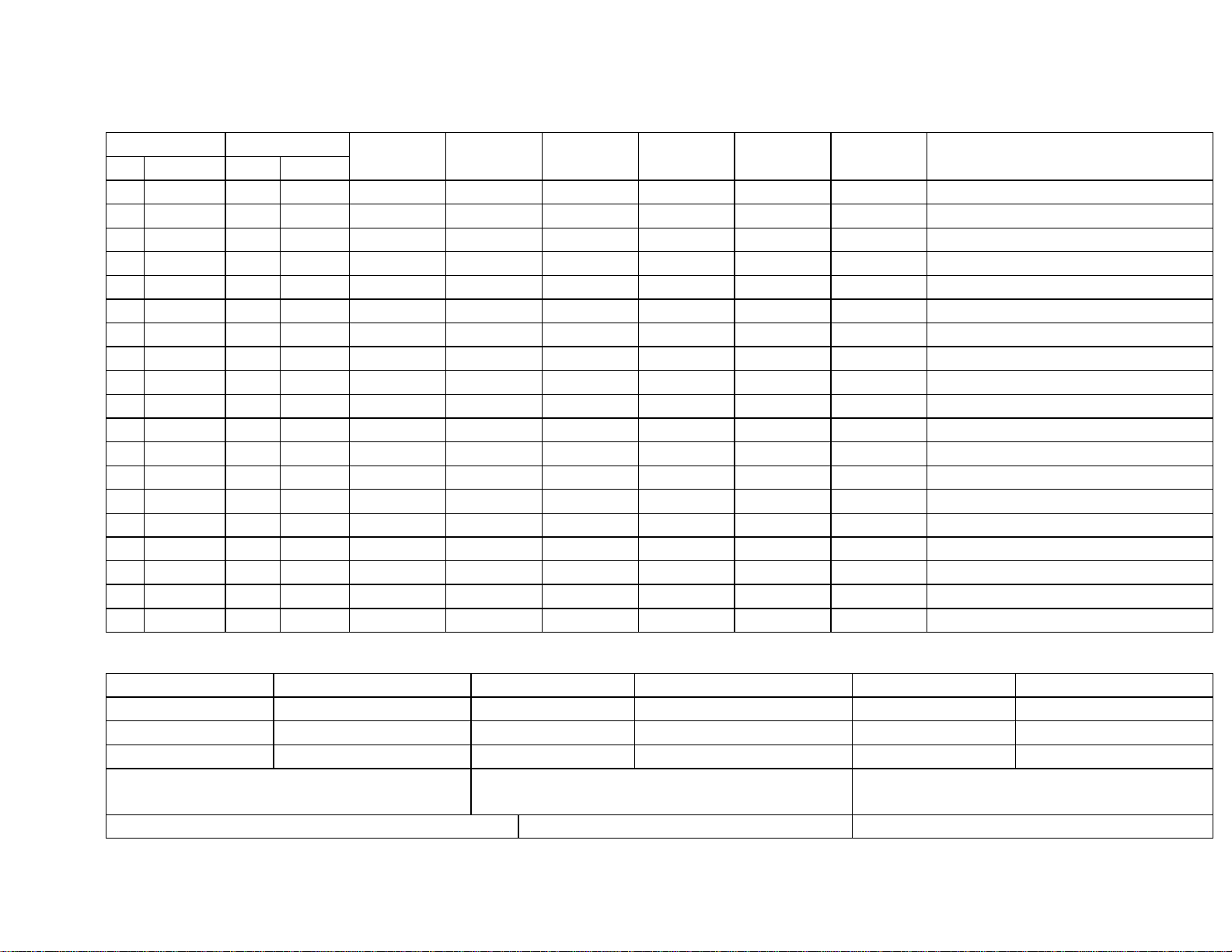
Calibration
Log Sheet
Field Load
# Name # Name
Set
After Calibration – Record C Values
Cal. Set Name:
C1 C1 C1
C2 C2 C2
C3 C3 C3
Comments:
Actual Indicated
Date Lbs Lbs Acres Yield Comments
Cal. Set Name:
Comments:
Cal. Set Name:
Comments:
Speed Sensor Pulses/Rev (under Vehicle Setup)
Page 64

Page 65

Calibration
Log Sheet
Field Load
# Name # Name
Set
After Calibration – Record C Values
Cal. Set Name:
C1 C1 C1
C2 C2 C2
C3 C3 C3
Comments:
Speed Sensor Pulses/Rev (under Vehicle Setup)
Actual Indicated
Date Lbs Lbs Acres Yield Comments
Cal. Set Name:
Comments:
Cal. Set Name:
Comments:
Page 66

Page 67
Calibration
Log Sheet
Field Load
# Name # Name
Set
After Calibration – Record C Values
Cal. Set Name:
C1 C1 C1
C2 C2 C2
C3 C3 C3
Comments:
Speed Sensor Pulses/Rev (under Vehicle Setup)
Actual Indicated
Date Lbs Lbs Acres Yield Comments
Cal. Set Name:
Comments:
Cal. Set Name:
Comments:
Page 68

Page 69

PF3000 Cotton Yield Monitor
4-1
Section Contents
Ag Leader Technology
Important Notices
The PF3000 Cotton Yield Monitor must be properly setup and calibrated.
Carefully read and follow the directions in the setup and calibration section
before using the PF3000.
This section contains instructions for the following items.
Fields and Loads 4-2
On Screen Mapping 4-4
Area Counting 4-6
Marking 4-8
Logging Map Data to a Card 4-10
Using a GPS Receiver 4-14
Using a Radar Gun 4-16
Diagnostic 4-17
Display Items 4-24
Summary 4-27
Swath Setting 4-31
Flow Sensor Alarms 4-32
Load Settings 4-35
Checking Data Accuracy 4-36
Updating Operating Program 4-39
Site Verification 4-41
Navigate 4-44
Boundary 4-49
Grid 4-52
Item Page
***
Operation Overview
March 2002
Page 70
PF3000 Cotton Yield Monitor
4-2
Fields and Loads
Recommendations
Field
Ag Leader Technology
All the information recorded by the PF3000 must be recorded in a field and
load. The field and load that the monitor is set on is found on the top line of
the main operating screen.
Fields
You should at least create all the fields and name them before you begin to
use the PF3000. You can create and name your fields using any operating
mode. You should choose field names that you can use year after year. If
you have multiple cotton monitors harvesting in the same field, setup the
same field names with the same field number. This will simplify merging
yield data into one map from multiple machines.
Loads
You can also create and name loads within fields before you use the
PF3000. New loads can be created on-the-fly. Load numbers do not have
to match between monitors of multiple machines in the field.
Definition:
Load: A load is used to subdivide a field into smaller sections. The
monitor load is not associated with the picker basket, wagon, or truck load.
Load
March 2002
Page 71

PF3000 Cotton Yield Monitor
4-3
Fields and Loads
Ag Leader Technology
Creating/Naming
Changing Fields
and
Loads
Instructions for creating and naming fields and loads are in the setup
section.
The top line of the display indicates the field and load, which are currently
selected. The monitor can display either field totals or load totals. If field
totals are displayed, the current load is not indicated.
Changing Field
If the field totals are not displayed, press the FIELD key twice and use the
UP or DOWN ARROW key to change the field. Press the ACCEPT key to
change to a different field.
Changing Load
Press the LOAD key twice and use the UP or DOWN ARROW keys to
scroll through the loads. Press the ACCEPT key to change to the different
load.
* * *
Fields and Loads
March 2002
Page 72
PF3000 Cotton Yield Monitor
4-4
On Screen Mapping
Introduction
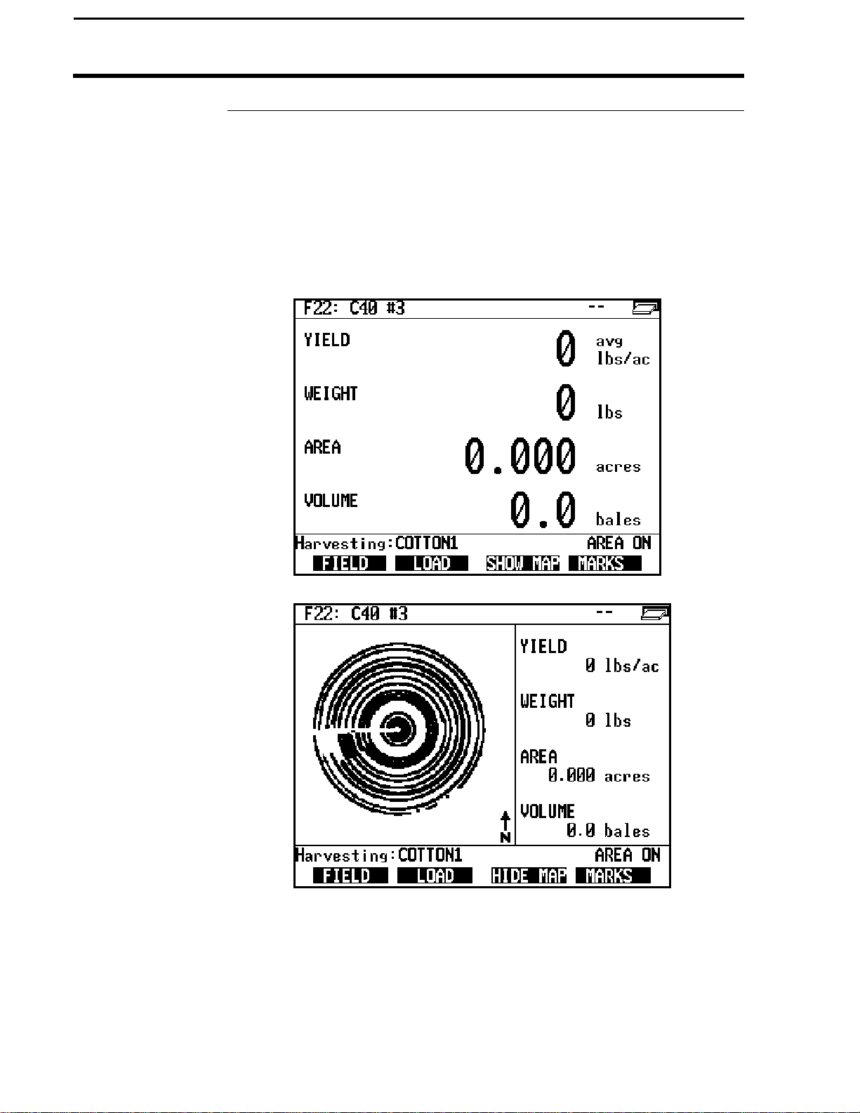
The PF3000 can show a coverage map on its display of the path the
combine, tractor or other vehicle has traveled for the field. The PF3000
makes the map from all the GPS data for the selected field that is on the
card inserted in the monitor.
The map only shows the path the vehicle has driven or covered, it does not
show any yield values.
Ag Leader Technology
March 2002
Page 73

PF3000 Cotton Yield Monitor
4-5
Ag Leader Technology
Making a Map
You must have the card that was used to log a field’s GPS data inserted into
the monitor to make an on the screen map for a field. You must also have
the log file that was used to log a field’s GPS data set as the current log file
at the card setup screen. If you used more than one log file to log the GPS
data for a field, you can only make a map from the GPS data that is on one
of the log files.
You can display the map on the go and watch it being created as you drive.
You can view the map at any time as long as the is in the monitor.
At this time you can only make a map for a field and not individual loads.
Follow the steps below to make a map.
Step Action
1 Set the monitor on the field for which you desire to make a map.
2 With the card inserted and the appropriate log file set as the current
log file at the card setup screen, press the SHOW MAP key. The
screen will change and the map will be displayed on the left half of
the screen and the other normal display items will be on the right
half of the screen.
3 Press the HIDE MAP key to stop viewing the map and see the
normal display items on the full screen.
NOTE:
• If the monitor is set on a field for which there is not any GPS data on
the card and you press the SHOW MAP key, the screen will still change
but the left half of the screen will be blank.
• The monitor automatically scales the map so that the largest view of the
map can be displayed in the left half of the screen.
* * *
On Screen Mapping
March 2002
Page 74

PF3000 Cotton Yield Monitor
4-6
Area Counting
Introduction
Stop Height
Area Count Stop
Beeps
Ag Leader Technology
In the bottom right corner of the display, the monitor always displays either:
• AREA ON
or
• AREA OFF
The area count switch is located on the bottom right corner of the front
panel. The switch manually controls area counting. The header sensor,
implement switch or spray booms automatically turns area counting on and
off if the area count switch is in the up position.
When the switch is in the down position, the monitor displays and flashes
"Area Off" and stops counting area.
When the switch is in the up position, the monitor will display "Area On"
and count area unless the header sensor, implement switch or spray booms
are connected and are automatically shutting off area counting.
The stop height number in the monitor determines at what head position the
monitor will turn on and off area counting. Refer to the calibrating stop
height instructions in the calibration section.
This setting determines how many times the monitor will beep to indicate
that the monitor is not counting area when turning on the ends. To view and
change the area count stop beeps you must press the SETUP key and then
the VEHICLE key. Instructions for changing the area count stop beeps are
in the setup section under vehicle setup.
NOTE:
• It is recommended that the area count stop beeps be set high enough so
that lowering the picker head after turning on the ends turns off the
beeping rather than the beeps just timing out. This gives the operator
an audible signal that the monitor is counting area again.
• Usually an area count stop beeps value of 20 to 30 is high enough.
March 2002
Page 75
PF3000 Cotton Yield Monitor
4-7
Ag Leader Technology
Ground Speed
Sensor
The monitor can record its ground speed from three different sources:
Ground Speed Sensor Primary Speed Sensor
Speed sensor on transmission WHEEL
Radar gun RADAR
GPS receiver (must be rated for accurate
ground speed, GPS2000/2100, Add-On
GPS3000/3100 and Trimble AgGPS receivers)
To view and change the ground speed sensor you must press the SETUP key
and then the VEHICLE key. Instructions for changing the speed sensor
setting are in the setup section under vehicle setup.
You have to calibrate distance for wheels, tracks, or radar, depending on
which ground speed sensor you use. Refer to the distance calibration
instructions in the calibration section.
The primary speed sensor type is recorded for each load. If you have
recorded data for several loads but, you had the wrong primary speed sensor
setting, you can switch the speed sensor setting on the loads. Refer to load
settings instructions in the operation instructions.
If you are getting your ground speed from a GPS receiver and you lose your
GPS signal, the monitor will take readings from the secondary speed sensor.
Area Counting
GPS
* * *
March 2002
Page 76

PF3000 Cotton Yield Monitor
4-8
Marking
Introduction
Ag Leader Technology
You must have a GPS receiver and memory card to do field marking. To
perform field marking you can use the internal marker selection keys built
into the PF3000 to identify the 4 marks available or connect the external
field marker device. You can not use both at the same time. You can make
marks in all operating modes of the PF3000.
IMPORTANT: Make sure that under the CONSOLE setup key, you
have the Field Marker set correctly to either INTERNAL or
EXTERNAL.
If you are using the internal marks, you can rename the marks and also set
them up as a continuous or spot mark. If you are using the external Field
Marker, you can not rename the marks but can do continuous or spot
marking.
Continuous marking
Making several marks in a row (for example: marking large weed
patches or tile lines).
Spot marking
Marking just one mark (for example: marking a rock or tile hole).
Setting Up Marks
Press the SETUP key and MARKS key to display the marker setup screen
and name and set the internal marks. If you are using the external Field
Marker, you do not need to make any settings on the Marker Setup screen.
Making Marks
You can mark more than one item at a time. When a mark is turned on the
monitor will beep and the mark will flash.
Follow the steps below to make marks when using the internal marks.
Step Action
1 Display FIELD, LOAD, MARKS on the bottom by pressing the
MENU key .
March 2002
Page 77

PF3000 Cotton Yield Monitor
4-9
Ag Leader Technology
Step
2 Press MARKS key.
Action
3
Marks that are set as a Continuous Mark
Press the marker key to start marking at the beginning of the area
you want to mark. Press the marker key again to stop marking
after you have driven through and reached the end of the area that
you want to mark.
Marks that are set as a Spot Mark
Press the marker key once when you are directly over the item you
want to mark. The monitor will log one mark and automatically
shut off the marking for that mark.
4 After you have finished marking, press the MENU key again to
display FIELD, LOAD, MARKS on the bottom.
Follow the steps below to make marks when using the external Field
Marker.
Continuous Marking:
Press the ON key on the appropriate switch at the start of the distance to
mark. Travel all the way through the distance, and at the end, press the OFF
key on that switch.
Spot Marking:
Press the MARK key once on the appropriate switch just as the vehicle
passes over the location of the item in the field.
Connecting
External Field
The external Field Marker connects to Port 1. Make sure that under
CONSOLE setup Field Marker is set to EXTERNAL.
Marker
Mapping Marks
* * *
The marks you make in the field are all logged to the memory card. If you
read your card into a mapping program, your marks should appear on your
yield map.
Marking
March 2002
Page 78

PF3000 Cotton Yield Monitor
4-10
Requirements
Log to Card
Logging Map Data on Card
Introduction
Memory Card
Setting Monitor to
The PF3000 can read position information from a GPS receiver and record
data for mapping. To save GPS data, you must use a memory card. You
must use a mapping software to download and archive data on a memory
card.
IMPORTANT: You must copy memory to every log file you create and
log to before you read the card into your computer. This is done
automatically when the monitor powers down with the card in the slot.
The following characteristics are required of memory cards you intend to
use with the monitor:
Card Type Sizes Specifications (all cards)
SANDISK ATA
Flash card
IMPORTANT: ATA Flash cards are the only brand of ATA Flash
cards that are guaranteed to work in the PF3000.
Note: 32 MB SANDISK ATA Flash cards are available from your Ag
Leader Technology dealer.
Press the SETUP key and CARD key to view the card setup screen. Set the
logging device to a card and select or create a log file.
If you turn the monitor on or start the picker fan(s) without a card in the
monitor and the monitor is set to log to a card, the monitor will display
"INSERT CARD. When you insert the card, a log file will be created and
the monitor will return to the main screen.
2 to 32 megabytes (max)
Ag Leader Technology
Type 1 or 2 PCMCIA
68-pin connection
200 ns speed rating
March 2002
Page 79

PF3000 Cotton Yield Monitor
4-11
Logging Interval
Ag Leader Technology
Setting the
Log File
Press the SETUP key and CARD key to view the card setup screen. Set the
logging interval to 1, 2 or 3 seconds.
When the monitor records a reading for any one of the logging intervals, it
takes an average of all the yield readings in that interval.
The number of hours of instantaneous data that can be logged on a memory
card depends on the card size and logging interval listed below.
Ag Leader 20 M
ATA Flash Card
Ag Leader 32 M
ATA Flash Card
NOTE: The logging hours available can vary from the numbers shown
above due to a variety of operating conditions. The number of fields and
loads, as well as the number of separate files copied to the memory card all
affect the log file size.
The number of readings taken per foot traveled are also dependent on your
logging interval:
3 mph
5 mph
The PF3000 requires a log file to store GPS data on a memory card. The log
file will always have a ".PFL" extension and be named with the date the file
was created.
Example: 98081502.PFL This file was the second log file created on
08/15/98.
Approximate Logging Hours Until Card is Full
1 sec 2 sec 3 sec
25.8 47.2 65.2
41.2 75.5 104.3
1 sec 2 sec 3 sec
4.4 8.8 13.2
7.3 14.6 21.9
Logging Map Data on Card
Distance Traveled (ft)
March 2002
Page 80
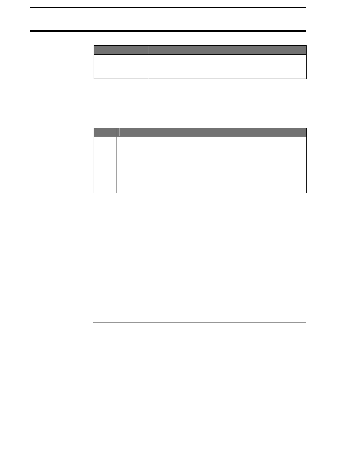
PF3000 Cotton Yield Monitor
4-12
Logging Map Data on Card
Type of Card Log file criteria
Inserting Memory
Cards
SANDISK ATA
FLASH card
In order to log instantaneous GPS data or copy field and load data to a
memory card, a log file must be selected. The monitor will prompt you
when you turn it on to select or create a log file. Refer to the steps below to
select/create a log file after you have turned the monitor on.
Step Action
1 With the memory card inserted into the PF3000, card setup screen
displayed, and "Log File" selected, press the EDIT key.
2 Use the UP or DOWN ARROW keys to select a log file. If a log
file does not exist on the card or you do not want to log to any of
the existing log files on the card, press the CREATE FILE key to
create a new log file.
3 With the desired file selected, press the ACCEPT key.
NOTE: After you read all the log files on your card into your computer
(and make backup copies of files), it is recommended to erase the log file(s)
on the card. This will prevent confusion on which files have been read into
your computer the next time you read the card.
IMPORTANT: Before you insert the memory card into the monitor,
touch the monitor with your hand to ground yourself and prevent any
static electricity transfer to the monitor through the card.
Insert the end of the card that has 68 small holes into the monitor with the
"front" side of the card (the side with the manufacturer’s name or logo)
facing up. Be sure to insert the card completely, so that it makes good
contact and remains in place. When you insert a memory card the card
symbol will appear in the top right corner of the display.
A new log file must be created for each day. Can not
add to an old log file after a new file has been created.
Can store multiple log files on one card.
Ag Leader Technology
March 2002
Page 81
PF3000 Cotton Yield Monitor
4-13
Memory Card
Space on Card
Ag Leader Technology
Formatting Card
Copying Data to
Log File
Logging Data to a
Operating Mode Condition to start logging to card
Checking Free
The memory card must be formatted with a DOS format. You can format
the card using the PF3000 or your computer and card reader (using
Windows 3.1 or Windows 95 and 98. Windows NT is not supported). Refer
to the instructions for formatting a card in the Card Setup section.
To copy memory to log files that are not set as the current log file, press the
SETUP key and CARD key. Press the SHOW FILES key and select one of
the log files. Press the FILE OPTIONS key and press the COPY TO FILE
key.
At the card setup screen, press the COPY TO CARD key to copy memory to
the file set as the log file (this is the same copy to card function that happens
during shut down).
When the monitor logs data to a memory card, a small arrow that points to
the memory card symbol at the top right corner of the display appears.
Cotton Harvest Mode Picker units engaged (fan speed must be above
To check the percent of space free on the card display CARD INFO.
IMPORTANT: Formatting a card erases all data on the card.
IMPORTANT: If you have logged to two or more files during
the day without coping to card; when you power down the
monitor, only the LAST log file will be copied to card.
2500 rpm) and the monitor is counting area.
Logging Map Data on Card
* * *
March 2002
Page 82

PF3000 Cotton Yield Monitor
4-14
Using a GPS Receiver
Introduction
Compatible GPS
Receivers
Mounting a GPS
Receiver
You can connect a GPS receiver to the PF3000 to collect field position
information for making a map. The GPS receiver sends the exact
coordinates in degrees latitude and degrees longitude to the monitor every
second. You must use a memory card with the monitor to record GPS
position information.
NOTE: If you are using the Add-On GPS 3000 or 3100, refer to the AddOn GPS General Instructions you placed in the Options Section for specific
instructions.
Almost all GPS receivers made for agriculture applications are compatible
with the PF3000 and thus meet the requirements listed below. Ag Leader
Technology sells a Coast Guard compatible receiver, the Add-On GPS 3000
and also a machined Coast Guard and Satellite differential compatible
receiver, the Add-On GPS 3100. Receivers other than the Add On GPS
3000/3100 must be configured to send GPS data according to the following
parameters:
• NMEA standard data output protocol
• 4800-X-8-1 communications protocol
• GGA data string—the only data string needed
• Send all messages once per second
NOTE: If you use the Ag Leader GPS 2000 or GPS 2100 , Trimble AgGPS
120, 122, 132 or other high accuracy receiver that outputs the VTG data
string, you can obtain ground speed readings from the GPS signal. If you
are using the Add-On GPS 3000/3100, you can get ground speed from it
also, but outputting the VTG string does not apply.
Follow the mounting instructions provided with the GPS receiver. Some
general guidelines are listed below for mounting the receiver on a vehicle.
• Make sure the GPS antenna is in the middle of the vehicle.
• Generally, the antenna should be the highest point on the vehicle.
• Keep the antenna away from "electrical noise" sources, such as a cab fan
• On most cotton harvesters, the center of the cab is the highest, safest
motor or the engine compartment.
place to mount the GPS antenna.
Ag Leader Technology
March 2002
Page 83

PF3000 Cotton Yield Monitor
4-15
Ag Leader Technology
Connecting a
Receiver to the
Monitor
GPS Status
Indicator
The GPS receiver connects to Port 1 on the monitor. The GPS receiver
normally has a separate power cable that connects to a 12-volt power
source. You can supply power to the GPS receiver through the GPS cable
that connects to Port 1. Pin 4 is switched 12 volts and pin 6 is ground.
The GPS manufacturer supplies the cable that connects the GPS receiver to
the monitor. If the cable provided with your receiver is not specifically
designed for the PF3000, you must use a GPS null modem cable that you
can purchase through your Ag Leader Technology dealer. You will know
that you need to use the GPS null modem cable if your GPS cable does not
insert into port 1 of the PF3000 or if the monitor does not receive the GPS
signal when the GPS cable is connected (no D or G in the top display).
IMPORTANT: Do not use a null modem that you buy from a store
because most have the wrong connections and can cause damage.
NOTE: The GPS null modem cable switches pins 2 and 3, and pin 5 goes
straight through. Refer to the reference section for the pin-outs of Port 1.
The PF3000 will display a "D" and "G" on the top right corner of the display
to indicate you have a GPS signal. If you do not have a GPS receiver
connected you will see two dashes "- -".
NOTE:
• A "D" indicates that you have a differential signal.
• A large "G" indicates that you have a GPS signal and your GPS
receiver is tracking four or more satellites.
• A small "g" indicates that you have a GPS signal but your GPS receiver
is tracking only three satellites.
Your GPS receiver must track four or more satellites (large "G") to get an
elevation reading.
* * *
Using a GPS Receiver
March 2002
Page 84
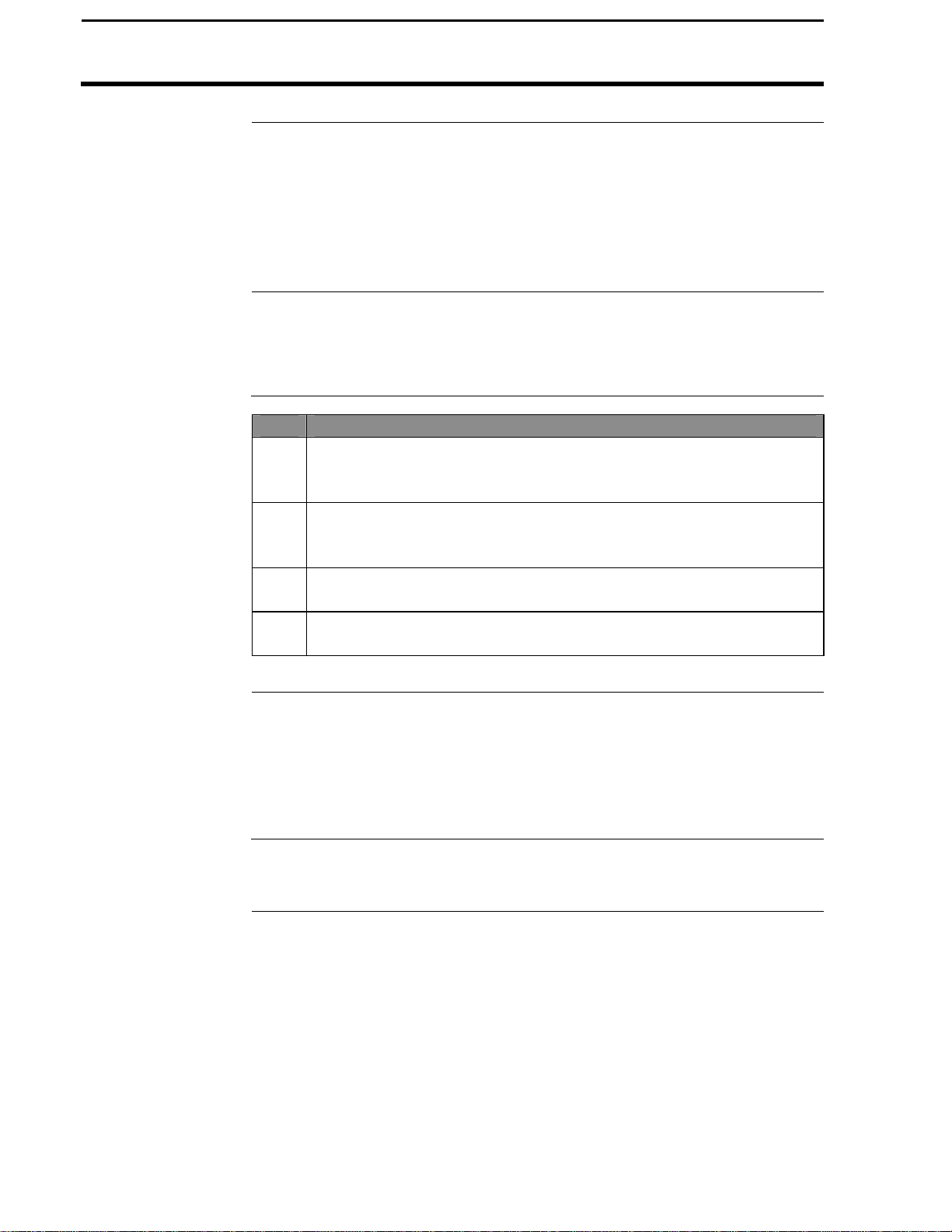
PF3000 Cotton Yield Monitor
4-16
Using a Radar Gun
Introduction
Necessary Cables
Installing a Radar
In a Cotton Picker
Changing Speed
Setting
Ag Leader Technology
To more accurately measure ground speed on sloping fields or in muddy
conditions where the wheels slip, you can use a radar gun. Sensors
compatible with the monitor are:
• Dickey-john • Case IH Magnum
• Magnavox • John Deere
• MicroTrak sonar gun
If you intend to use a radar gun, you must buy a radar cable for your specific
sensor from an Ag Leader Technology dealer.
Step Action
1 Disconnect the existing ground speed cable from your picker speed
sensor at the distribution cable. Leave the cable routed in case you
want to use the picker’s speed sensor again.
2 Mount the radar unit on the picker in a position where it will not be
damaged and will be aimed between plant rows. Consult your
installation instruction.
3 Route the radar cable (or if Dickey-john, the radar unit's integral
cable) to the Distribution cable of the PF3000.
4 Connect the radar cable (if Dickey-john, integral cable) to the four-
pin round connector on the distribution cable.
Press the SETUP key and VEHICLE key to view the vehicle setup screen.
Refer to the vehicle setup instructions in the setup section and change the
primary speed sensor to "Radar". You must perform a distance calibration
for radar. Refer to the distance calibration instructions in the calibration
instructions.
***
March 2002
Page 85

PF3000 Cotton Yield Monitor
4-17
Ag Leader Technology
Introduction
The diagnostic screens provide troubleshooting and reference information
for the PF3000.
Order of Keys
(Harvest Mode)
Press the MENU key until you see the following keys on
the display.
Press the DIAG key to
view the following
setup menu items.
Press the bottom LEFT or RIGHT ARROW keys to
Diagnostics
March 2002
Page 86
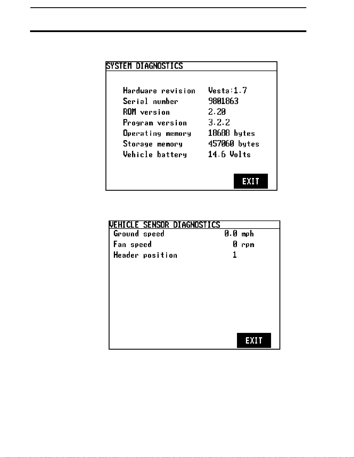
PF3000 Cotton Yield Monitor
4-18
Diagnostics
Ag Leader Technology
The following are examples of diagnostic screens:
March 2002
Page 87

PF3000 Cotton Yield Monitor
4-19
Ag Leader Technology
Diagnostics
March 2002
Page 88

PF3000 Cotton Yield Monitor
4-20
DIAGNOSTICS: FLOW DATA
SENSOR
RAW FLOW
TIME
NUM
STATUS
1 0 10 1 OK
2 0 10 1 OK
DIAGNOSTICS: SENSOR DATA
3 0 0 0 0 0
4 0 0 0 0 0
Diagnostics
Flow Data Screen
Ag Leader Technology
This screen shows the raw flow readings from each sensor broken down by
each lens.
3 0 10 1 OK
4 0 10 1 OK
SENSOR
DATA
EXIT
SENSOR A B C D E
1 0 0 0 0 0
2 0 0 0 0 0
EXIT
March 2002
Page 89
PF3000 Cotton Yield Monitor
4-21
DIAGNOSTICS: SIGNAL STRENGTH
SENSOR
A B C D E
1 8120
10659
10985
10258
9269
DIAGNOSTICS: SENSOR INFO
SENSOR
HW REVISION
FW REVISION
4 2.0 2.11
Ag Leader Technology
Signal Strength
This screen shows the signal strength from each sensor broken down by
each lens. This number is used to indicate the amount of light coupled from
the emitter to the detector. After a new installation and before picking, this
value should be greater than 8000 or higher.
Diagnostics
2 9145 8736 8000 9602 9387
3 8630 9842 10089 9367 8934
4 10367 11356 10758 9158 9698
Sensor Info
EXIT
This screen shows the hardware and firmware revisions of each sensor.
1 2.0 2.11
2 2.0 2.11
3 2.0 2.11
EXIT
March 2002
Page 90
PF3000 Cotton Yield Monitor
4-22
SENSOR
TMO
CSUM
FRAME
OVRFL
NORSP
NODAT
1 0 0 0 0 0 0
2 0 0 0 0 0 0
3 0 0 0 0 0 0
4 0 0 0 0 0 0
SENSOR
PKT CSUN
PKTFR
ADDR
FRAN
ORUN
1 0 0 0 0 0 0
2 0 0 0 0 0 0
3 0 0 0 0 0 0
Diagnostics
Sensor Com
Ag Leader Technology
This screen shows communication errors detected by the monitor broken
down by sensor
DIAGNOSTICS: SENSOR COMM
RESET
PORT
SENSOR
EXIT
DIAGNOSTICS: SENSOR
4 0 0 0 0 0 0
MESSAGES
March 2002
EXIT
Page 91
PF3000 Cotton Yield Monitor
4-23
Port Diagnostics
DIAGNOSTICS: SENSOR COMM
SENSOR
TMO
CSUM
FRAME
OVRFL
NORSP
NODAT
1 0 0 0 0 0 0
2 0 0 0 0 0 0
DIAGNOSTICS: PORT
Rx Errors
Frame
Noise
0 0
Sensor Message
Receive
Transit
0 0 0
Sensor Tracks:
Address
Checksum
Total ACK’s
NAK’s
Messages
0 0 0
Ag Leader Technology
This screen shows the total communication errors detected by the monitor.
Diagnostics
3 0 0 0 0 0 0
4 0 0 0 0 0 0
RESET
PORT
SENSOR
EXIT
Parity Overrun
0 0
Buffer Overflows:
MESSAGES
EXIT
March 2002
Page 92

PF3000 Cotton Yield Monitor
4-24
Display Items
Introduction
Selection
Box
Ag Leader Technology
The PF3000 has four display lines for viewing items. You can choose what
items you see on the display and the position that the items appear on the
display.
To change the display item on a display line you must select the line. The
four keys to the right of the display each select a display line. A rectangular
box surrounds the display line to show that that line is selected.
When the display line is selected the four menu items on the bottom change
and show items you can select for display. Press a key below a display item
to put a different display item in place of the selected display item. There
are more than four display items to choose for viewing. Press the bottom
LEFT or RIGHT ARROW keys to scroll to the right or left and view other
display items on the bottom.
When some display items (like swath) are selected, an up and down arrow
symbol will appear on the right of the display line. This indicates you can
change the setting of the item with the UP or DOWN ARROW keys. After
you have made the change you must press the key to the right of the display
line to deselect the line.
March 2002
Page 93

PF3000 Cotton Yield Monitor
4-25
Ag Leader Technology
Field and Load
Totals
Harvest Display
Items
When the following are displayed you can see a field, load total or average.
Yield Volume
Weight Lint Weight
Area Lint Yield
To view a field total you must have the field displayed without the load.
Press the FIELD key to display the field alone on the top line. To view a
load total, you must have the load displayed with the field on the top line.
Press the LOAD key to display the load on the top line.
Below are listed in order the available display items for the harvest mode.
YIELD
This displays the instantaneous seed cotton yield in pounds per acre (kg per
hectare) while you are harvesting. If you are not harvesting, the average
yield is displayed. If you select this line it will also show the average yield
while you are harvesting.
WEIGHT (seed cotton)
Displays the total weight of seed cotton of that load or field in pounds (kg)
AREA
This displays the area harvested for the current field/load in acres (hectares).
SWATH
This displays the swath width of the picker in feet (meters) or as the number
of rows. If you have swath selected, you can use the UP or DOWN arrow
keys to set a partial swath and adjust it back to full swath again.
LINT YIELD
This displays the instantaneous lint yield per acre while you are harvesting.
This can be displayed as either bales per acre or lbs per acre. If you are not
harvesting, the average yield is displayed. If you select this line it will also
show the average yield while you are harvesting. This is calculated using
the lint percent turnout entered under its calibration set.
LINT WEIGHT
Displays the total weight of the lint cotton of that load or field in pounds
(kg). This is calculated using the lint percent turnout entered under its
calibration set.
Display Items
March 2002
Page 94

PF3000 Cotton Yield Monitor
4-26
Display Items
Ag Leader Technology
VOLUME
This displays the total volume of the current load in bales. A bale is defined
to be equivalent to 480 pounds (217.7 kg) of lint, but is configurable in the
Calibration Set setup screen.
COTTON FLOW
This displays the instantaneous seed cotton flow rate in pounds per hour (kg
per hour).
FAN SPEED
This displays the fan speed in rpm.
GROUND SPEED
This displays the vehicle ground speed in miles per hour (km per hour).
DISTANCE
This displays the total distance traveled for the current load in feet (meters).
AREA PER HR
This displays the instantaneous area harvested in acres per hour (hectares
per hour).
LAT LON
This displays the latitude and longitude coordinates and the elevation from
the GPS receiver.
DATE TIME
This displays the current date and time.
CARD INFO
This displays the free space available on the card.
HEAD HEIGHT
This displays a number to indicate the position of the head. This number is
not in feet or inches, but is a number that is relative to the height of the
head.
* * *
March 2002
Page 95
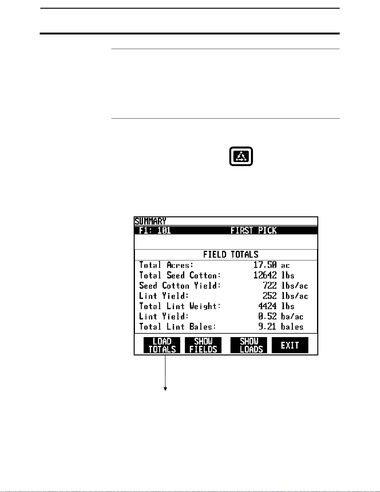
PF3000 Cotton Yield Monitor
4-27
Summary Screen
Ag Leader Technology
Introduction
The summary screen shows totals and averages for the fields and loads. You
can also see the field and load totals on the main operating screen (refer to
the display item instructions).
You can view items on the summary screen on the go. You should use the
summary screen to view data from loads you have previously harvested.
To view the summary screen press the:
Once you have finished viewing the summary screen press the EXIT key.
Summary
MENU key
SUMMARY key
February 2001
Page 96
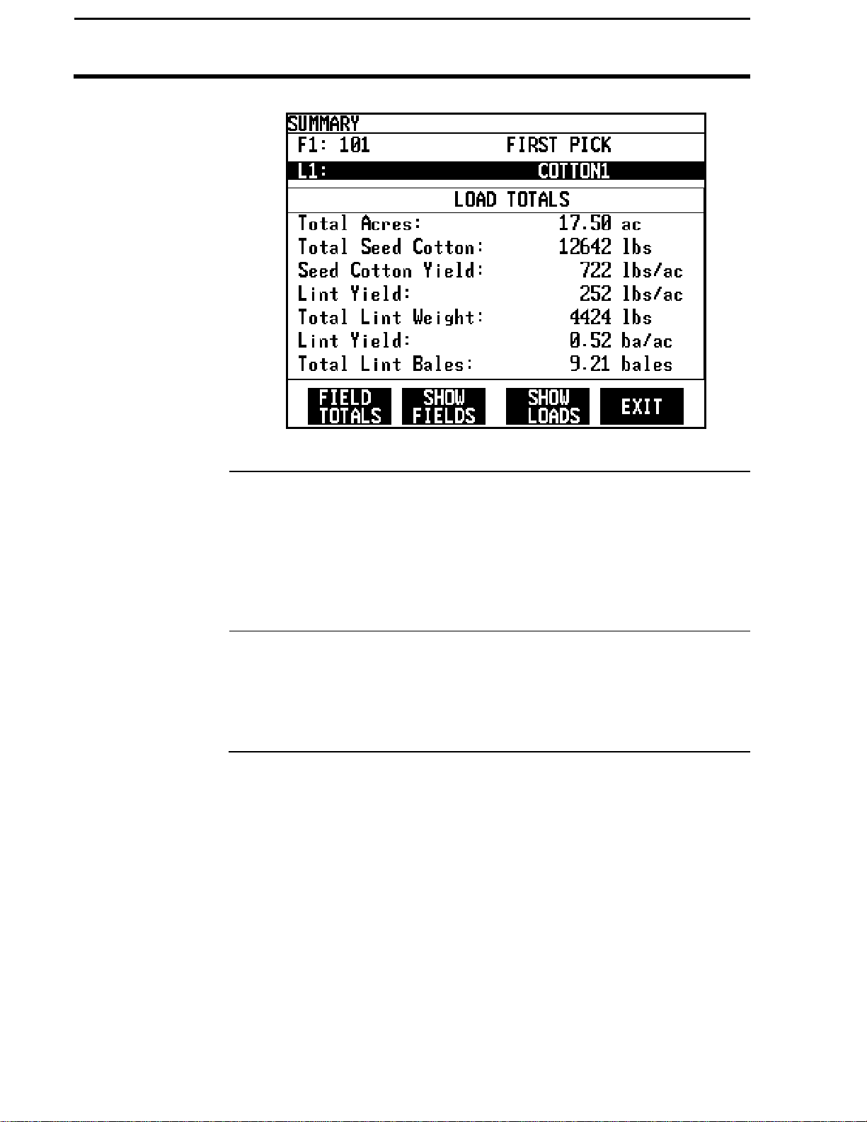
PF3000 Cotton Yield Monitor
4-28
Summary
Changing Field
and Load
Field and Load
Totals
Ag Leader Technology
The first key on the menu selection line displays LOAD TOTAL. When
LOAD TOTALS is pressed, the active load is displayed on the second line.
The first menu key will display FIELD TOTALS. The title for the summary
table reflects the highlighted item. When FIELD TOTALS is displayed
when the field line is highlighted. When LOAD TOTALS is displayed
when the load line is highlighted.
If load is displayed with the field, then the totals and averages are for the
load.
If the field only is displayed, then the totals and averages are for the field.
March 2002
Page 97

PF3000 Cotton Yield Monitor
4-29
Ag Leader Technology
Show Fields
Press the SHOW FIELDS key to view a list of all the fields as shown below.
If you have several fields you will have to use the UP or DOWN ARROW
keys to scroll through the all the fields.
One of the fields will be selected or highlighted. You can change the field
that is selected by using the UP or DOWN ARROW keys. When you press
the EXIT key, the monitor will return to the main summary screen showing
the data for the field that was selected.
Example of a field summary screen:
Summary
March 2002
Page 98
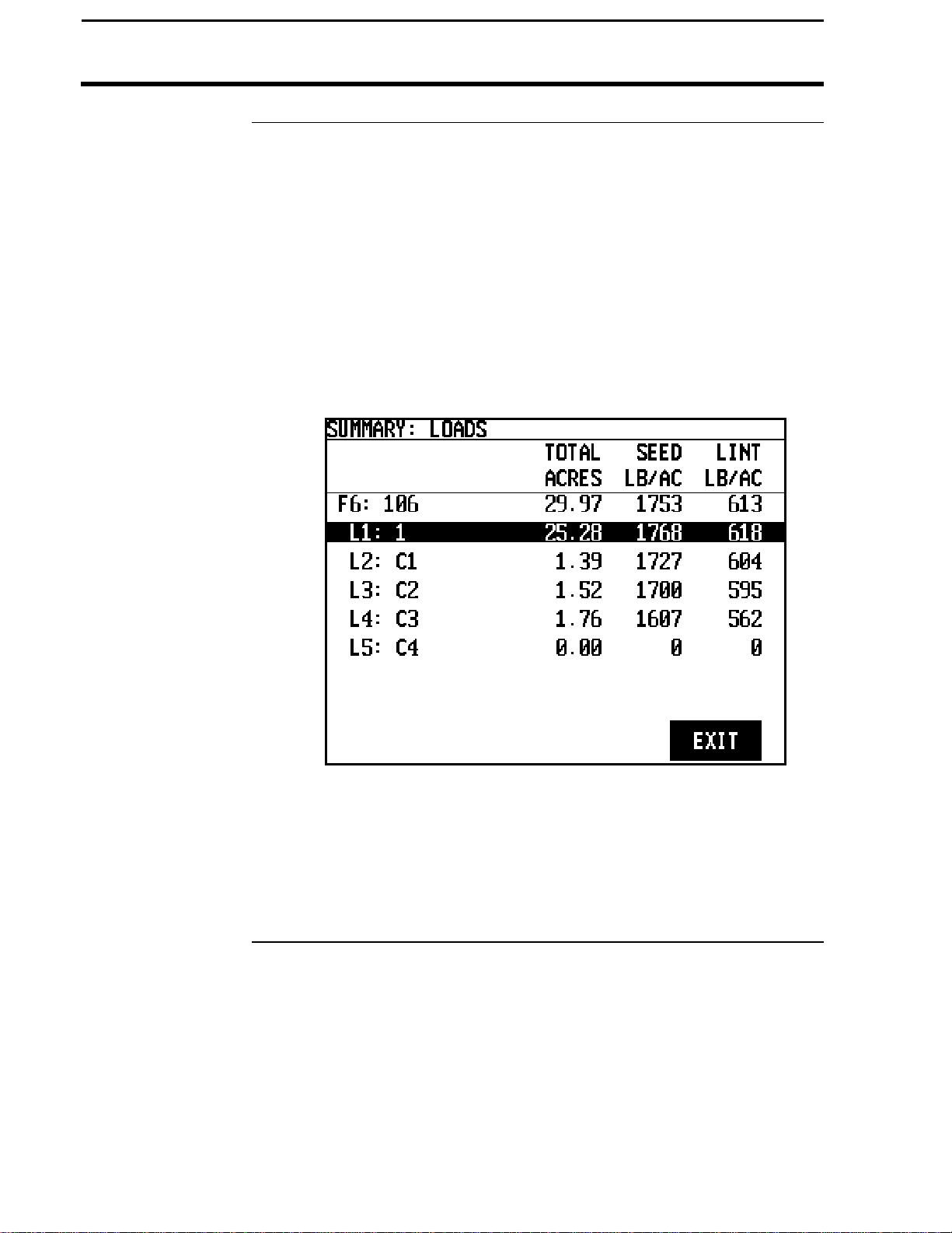
PF3000 Cotton Yield Monitor
4-30
Summary
Show Loads
Ag Leader Technology
Press the SHOW LOADS key to view a list of all the loads in the field as
shown below. If you have several loads you will have to use the UP or
DOWN ARROW keys to scroll through the all the loads.
One of the loads will be selected or highlighted. You can change the load
that is selected by using the UP or DOWN ARROW keys. When you press
the EXIT key, the monitor will return to the main summary screen showing
the data for the load that was selected.
Example of a load summary screen:
* * *
March 2002
Page 99
PF3000 Cotton Yield Monitor
4-31
Ag Leader Technology
Introduction
Full Swath
Partial Swath
The monitor uses the number of rows and row space you set in the monitor
to determine the total swath.
The full swath is the normal swath that the vehicle takes during field
operation. It is the permanent swath based on the number of picker units.
To view and change the full swath settings, you must press the SETUP key
and then SWATH key. In the case of a broadcast type header, configure the
vehicle to the most rows, then change the Full Swath to reflect the actual
swath of your header. Refer to the swath setup instructions in the setup
section for more instructions.
You can temporarily enter a partial swath setting when you encounter a less
than full swath during field operation (for example point rows). Follow the
steps below to enter a partial swath.
Step Action
1
If... Then...
Swath is displayed on
the main operating
screen
Swath is not displayed
on the main operating
screen
2 With swath selected, press the DOWN ARROW key to decrease the
swath to the appropriate swath width.
3 After you have finished the partial swath in the field, press the UP
ARROW key to increase the swath back to a full swath.
4 Deselect swath by pressing the key to the right of swath.
NOTE: When you decrease the swath, the monitor will beep to
remind the operator that the monitor is set on a partial swath. The
monitor will not stop beeping until the swath is increased to the full
swath.
Press the key to the right of the line
displaying swath to select the line
(rectangular box surrounding line).
Press one of the four keys to the right of
the display and display swath on the main
screen. Press the key to the right of the
line displaying swath to select the line
(rectangular box surrounding line).
* * *
Swath Setting
March 2002
Page 100
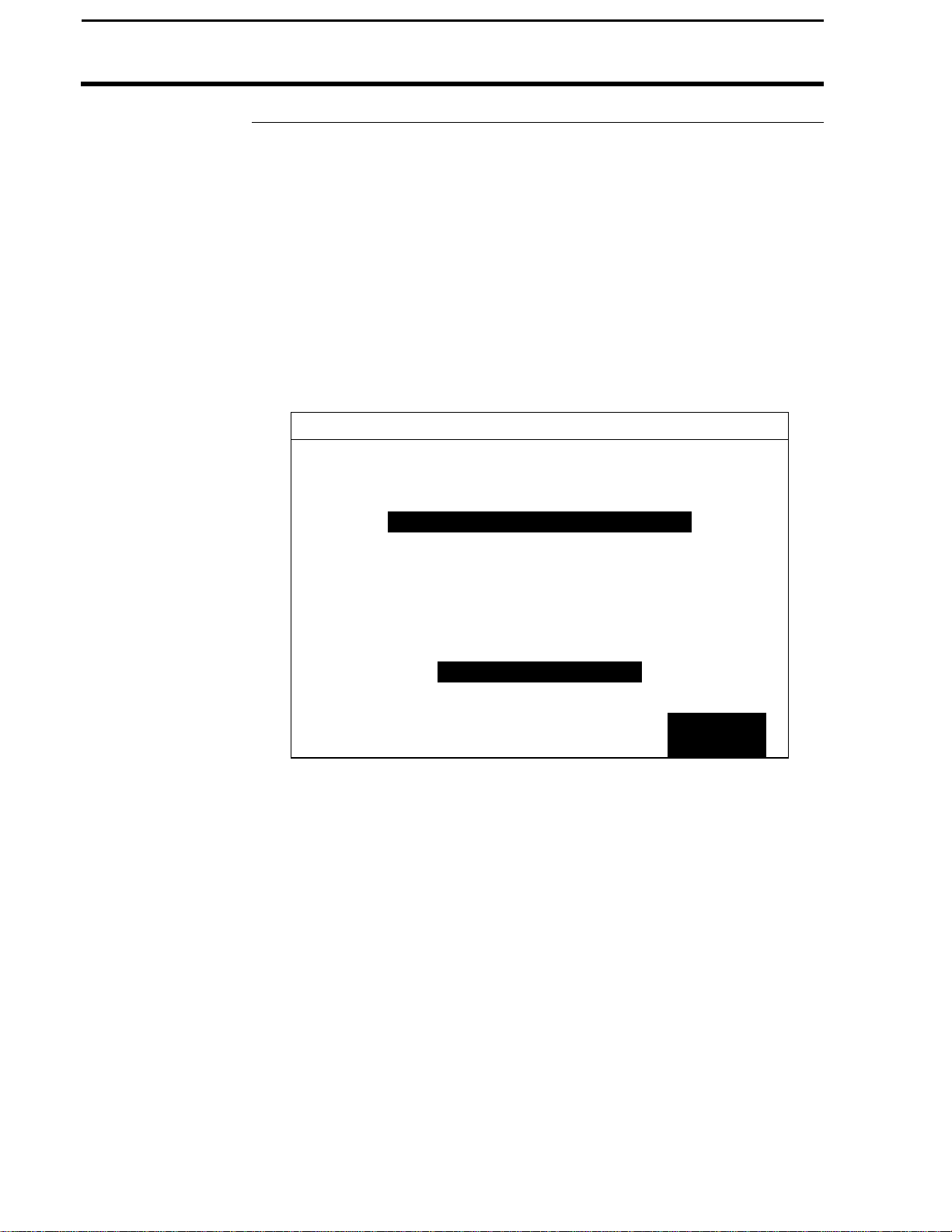
4-32
PF3000 Cotton Yield Monitor
Flow Sensor Alarms
Introduction
Alarm Activation
Communications
Alarm
The flow sensor alarms warn you when one or more flow sensors are not
operating. The types of alarms are Communications, Low Signal, Stringer
and Choke.
The activation of the alarm will be by a buzzer sounding and a full screen
message telling you which sensors are not sending data to the yield monitor.
Simply note which sensors are reporting and press the CANCEL key.
This alarm warns you to sensors that are not operating properly resulting in
lost yield data. The example below shows sensor communication alarms for
sensors 1 and 4 for a Case-IH picker
COTTON SENSOR ERROR
ALARM CONDITION
FLOW SENSOR NOT RESPONDING
CHECK FLOW SENSOR
Ag Leader Technology
1F
4R
CANCEL
March 2002
 Loading...