

Page 1
Welcome to the world of precision,
hands-free steering
OPERATOR’S MANUAL
2012-09 PN 602-0295-01 REV B
Page 2

Page 3

Important Information
Refer to your hardware installation manual for complete installation requirements before operating the GeoSteer system.
Trademark
All brands and products names, unless otherwise stated, are registered trademarks of Novariant, Inc.
Technical Support
Contact your dealer for technical support.
Copyright © 2012 All Rights Reserved
Operator’s Manual i
Page 4

LEGAL DISCLAIMER
Note: Read and follow ALL instructions in this manual carefully before installing or operating the GeoSteer1 system.
Note: Take careful note of the safety information in the Safety Information section of this manual and the additional safety
messages provided throughout this and any other supplemental manuals provided.
The manufacturer disclaims any liability for damage or injury that results from the failure to follow the instructions, cautions,
and warnings set forth herein.
Please take special note of the following warnings:
1. There is NO obstacle avoidance system included with the manufacturer’s product. The owner must always have a human
present in the operator’s seat of the vehicle when the GeoSteer system is in use to look for any obstacles to avoid
including people, animals, trees, ditches, buildings, etc. and take control of the vehicle to manually avoid them if
necessary.
2. The GeoSteer system does NOT control the speed of the vehicle. The operator must always adjust the speed of the vehicle
manually so that it is operated at a safe speed that will not cause the vehicle to roll over or go out of control.
3. The GeoSteer system will take over control of the vehicle’s steering system when the GeoSteer system is activated during
testing, calibration, tuning, and automatic steering operations. The vehicle’s steering axles, tracks, articulation point, or
wheels may move unpredictably when activated. Prior to starting the vehicle and/or activating the GeoSteer system, verify
that all people and obstacles are clear of the vehicle to prevent death, injury, or damage to property.
4. Use of the GeoSteer system is NOT permitted while the vehicle is on public roads or in public areas. Verify that the
system is powered OFF before driving on roads or in public areas.
Safety Information
Warning Alerts
The GeoSteer system installer and manufacturer disclaim any responsibility for damage or physical harm caused by failure to
adhere to the following safety requirements:
•
As the operator of the vehicle, you are responsible for its safe operation.
•
The GeoSteer system is not designed to replace the vehicle’s operator.
Note: After the installation of the GeoSteer system, verify that all the screws, bolts, nuts, and cable connections are tight.
Verify that all the cables and hoses have been secured to prevent them from being damaged. If any of the hydraulic lines or
fittings were loosened during the installation, verify that they have been reattached and tightened to prevent oil leaks
1
GeoSteer is a registered trademark of Novariant, Inc
ii GeoSteer System
Page 5
To understand the potential hazards associated with the
operation of a GeoSteer equipped vehicle, read the
provided documentation prior to installing or operating the
GeoSteer system on a vehicle.
To prevent accidental death or injury from being run over by
the vehicle, never leave the vehicle’s operator seat with the
GeoSteer system engaged.
To prevent accidental death or injury from being run over by
the vehicle verify that area around the vehicle is clear of
people and obstacles before startup, calibration, tuning, or
use of the GeoSteer system.
To prevent the accidental engagement of the GeoSteer
system and loss of vehicle control, shut down the GeoSteer
system while driving on roads. Never drive on roads or in
public areas with the GeoSteer system powered up.
Operator’s Manual iii
Page 6
Verify that you are in a stable position on the vehicle’s
platform or stairs when installing or removing the GeoDock
(the antenna assembly on top of the cab) so you do not fall.
If the vehicle does not provide a safe platform, use a ladder
to safely access the vehicle’s roof.
To avoid electrical shock hazards, remove the GeoDock
and/or other antennas from the vehicle before driving under
low structures or low electrical power lines.
High-Pressure Fluid Hazard
If the installation requires working on the hydraulic system
on the vehicle, read and understand the hydraulic sections
of the vehicle manufacturer’s operators manual before
starting the installation. Wear hand and eye protection while
performing hydraulic system maintenance. Relieve hydraulic
system pressure before servicing the hydraulic system.
If the vehicle has a Wheel Angle Senor as part of the
installation, always shut off the vehicle when working
around the Wheel Angle Sensor while installing, checking,
and adjusting the Wheel Angle Sensor and rod lengths. The
steering mechanism could move suddenly and cause
severe injury or death.
iv GeoSteer System
Page 7
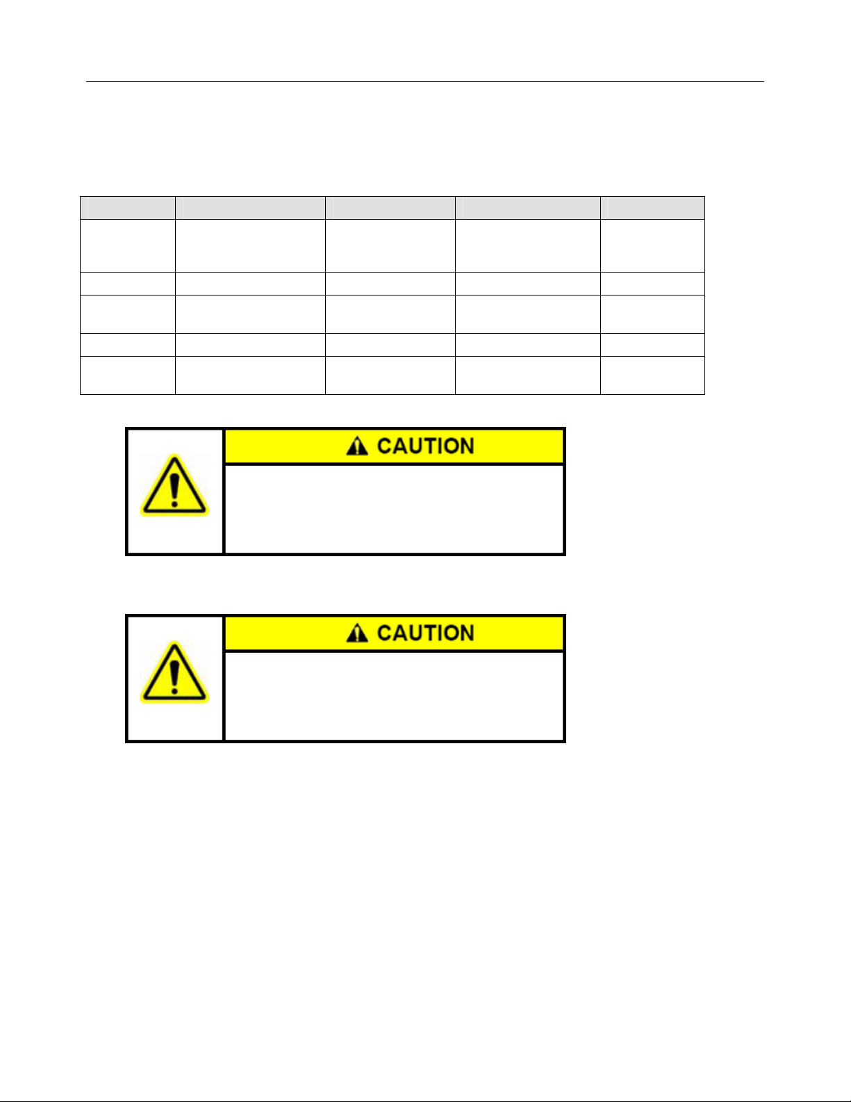
Caution Alerts
The GeoSteer system installer and manufacturer disclaim any responsibility for damage or physical harm caused by the failure
to adhere to the following safety requirements:
The GeoDock must be removed when transporting or
driving the vehicle at speeds above 31 mph (50 km/h). The
GeoDock can possibly detach due to wind loads at higher
speeds.
The GeoSteer system does not detect obstacles in the
vehicle’s path. The vehicle operator must observe the path
being driven and take over steering manually if an obstacle
must be avoided.
The GeoSteer system does not control the speed of the
vehicle. The operator must manually adjust the speed of the
vehicle to keep the vehicle safely under control.
The GeoSteer system must be powered OFF when
installing or removing the GeoDock, GeoSteer Control Unit,
or any other part of the GeoSteer system.
Operator’s Manual v
Page 8

The GeoDock must always be firmly secured to the
mounting plate via the magnet whenever the vehicle is in
operation to prevent the GeoDock from releasing from its
bracket and falling and to ensure the GeoDock is placed at
the same point every time.
REGULATORY INFORMATION
United States
FCC Class A Statement – Notice to Users; The GeoSteer system has been tested and found to comply with the limits for a
Class A digital device, pursuant to Part 15 of the FCC rules. These limits are designed to provide reasonable protection against
harmful interference in a residential installation. This product generates, uses, and can radiate radio frequency energy and, if
not installed and used in accordance with the instructions, may cause harmful interference to radio communication. However,
there is no guarantee that interference will not occur in a particular installation. Changes and modifications not expressly
approved by the manufacturer or registrant of this equipment can void your authority to operate this equipment under Federal
Communications Commission rules.
Our product complies with Part 15 of FCC Rules. Operation is subject to the following two conditions:
1. This device may not cause harmful interference.
2. This device must accept any interference received, including interference that may cause undesired operation.
Canada
The GeoSteer system conforms with the regulatory requirements of the ICES-003 Issue 4 February 2004; and VCCI V3/2009.04, and V-4*/2009.04, R-3074 and G-353.
European Union
The GeoSteer system is intended to be used in any of the 27 EU member countries. The GeoSteer system has been tested and
found to comply for CE and e Mark with the requirements in EN 55024:1998/A1:2001/A2:2003; EN 55022:2006/A1:2007,
Directive 2009/64/EC, IEC 61010-1 Safety, ETSI EN 301 489-1 V1.9.2 and ETSI EN 301 489-3 V1.4.1.
Australia and New Zealand
The GeoSteer system conforms to the regulatory requirements of the Australian Communications and Media Authority
(ACMA) AS/NZS CISPR 22:2009 for a Class A device, thus satisfying the requirements for C-Tick Marking and sale within
Australia.
vi GeoSteer System
Page 9
Compliance Information
The GeoSteer Control unit can contain an internal cellular-modem and can send signals through wireless technology or through
an external data communications radio. Table 1-1 lists these components and their related compliance approval numbers.
Table 1-1 Radio Compliance Information
Manufacturer Description FCC ID Europe Canada IC
Modem CDMA used for
Telit
Telit Modem GSM for Europe R17UC864G 0984 5131A-UC864G
Telit
Freewave Radio Receiver 900 MHz KNY-42182112519 NA 2329B-FGR2
Satel
North America and
Canada
Modem GSM for
Australia
Modem Receiver 403-470
MHz MRB0SATELTA10
This is a class A product. In a domestic environment this
product may cause radio interference. Do not place the
radio/cellular modem antennas within 7.9 inches (20.0 cm)
from other transmitting device antenna.
FCC RF Exposure Requirements require the user not to
operate the transmitter when someone is within 7.9 inches
(20.0 cm) from the antennas.
R17CC864 NA R17CC864
R17UC864G 0984 5131A-UC864G
2422A-SATELTA10 0523 NA
Operator’s Manual vii
Page 10

Table of Contents
Chapter 1 System Overview .............................................................................................. 1
Overview.......................................................................................................................................1
GeoSteer System Installation Overview .......................................................................................2
1
Display Kits.......................................................................................................................3
2
GeoSteer System Kits........................................................................................................3
GeoSteer CDMA ...........................................................................................................4
GeoSteer No Cell........................................................................................................... 5
GeoSteer GSM Europe ..................................................................................................6
GeoSteer GSM Australia ............................................................................................... 7
GeoDock Pro .................................................................................................................8
GeoDock Pro – No Cell................................................................................................. 8
3
Vehicle Installation Kits....................................................................................................8
4
Accessory Kits...................................................................................................................9
Accessing AutoSteer Setup Screens..............................................................................................9
Transferring GeoSteer from Vehicle to Vehicle .........................................................................10
Removing the GeoSteer System from a Vehicle..................................................................11
Installing the GeoSteer System on to Vehicle......................................................................13
Changing SIM Card in GeoSteer ................................................................................................16
GeoSteer Control Unit LED Diagnostics....................................................................................19
Chapter 2 Vehicle Tab..................................................................................................... 21
Overview.....................................................................................................................................21
Setup Wizard...............................................................................................................................22
Additional Steps for the First Time the Setup Wizard is Run..............................................22
WAAS/EGNOS Setup................................................................................................. 22
Set RTK Radio Modem Channel or Frequency........................................................... 24
Set OmniSTAR Options .............................................................................................. 25
Precision Preference Selection..................................................................................... 26
Standard Setup Wizard Steps...............................................................................................27
Select Vehicle Type..................................................................................................... 28
Select Vehicle Make .................................................................................................... 29
Select Vehicle Model................................................................................................... 29
Select Controller Type................................................................................................. 30
Naming the Vehicle ..................................................................................................... 31
Wheel Base .................................................................................................................. 31
Antenna Fore/Aft......................................................................................................... 32
Antenna Lateral Offset.................................................................................................33
Antenna Height............................................................................................................ 34
GeoSteer Fore/Aft........................................................................................................ 35
GeoSteer Lateral Offset ............................................................................................... 36
GeoSteer Height........................................................................................................... 37
GeoSteer Orientation ................................................................................................... 38
Save Changes............................................................................................................... 41
Manual Steering Override............................................................................................ 42
Manage Vehicle ..........................................................................................................................45
Select....................................................................................................................................45
Edit.......................................................................................................................................46
Delete...................................................................................................................................47
Export/Import Vehicles........................................................................................................48
Export to Display USB ................................................................................................49
Import from Display USB............................................................................................50
viii GeoSteer System
Page 11

Auto Calibrate.............................................................................................................................53
Common Calibration Steps..................................................................................................54
Compass Calibration.................................................................................................... 55
Wait For Heading ........................................................................................................55
Tilt Zero Initial Direction ............................................................................................56
Tilt Zero Opposite Direction........................................................................................ 57
Vehicle Type Specific Calibration Steps .............................................................................57
Valve / Steer-by-Wire.................................................................................................. 57
Mechanical Steering Unit / OnTrac2+......................................................................... 60
CAN Bus / ISO Controllers ......................................................................................... 62
Adjust Lateral Offset............................................................................................................63
Steering Adjust............................................................................................................................65
Steering Components..................................................................................................................65
ECU .....................................................................................................................................66
Manual Steering Override....................................................................................................66
Wheel Angle Sensor ............................................................................................................67
Zero Curvature............................................................................................................. 68
Hydraulic Valve...................................................................................................................69
ECU Sensors........................................................................................................................70
CAN.....................................................................................................................................71
Actuator ...............................................................................................................................71
Manual Steering Override (for Steering Encoders)..............................................................73
OnTrac2 ECU ......................................................................................................................73
MDU....................................................................................................................................74
Chapter 3 System Tab .................................................................................................... 77
Overview.....................................................................................................................................77
System Health .............................................................................................................................78
Manage Settings..........................................................................................................................79
Log Files ..............................................................................................................................79
Copy to Display USB .................................................................................................. 80
Delete........................................................................................................................... 80
Database...............................................................................................................................81
Backup to Display USB............................................................................................... 82
Restore from Display USB .......................................................................................... 82
Reset Factory Default ..........................................................................................................85
Reset ............................................................................................................................85
Accessories .................................................................................................................................86
Remote Switch............................................................................................................. 86
Enable (Disable) .......................................................................................................... 87
Technician...................................................................................................................................87
Software Upgrade .......................................................................................................................88
Upgrade Procedure ..............................................................................................................88
Chapter 4
GPS Tab ......................................................................................................... 91
Overview.....................................................................................................................................91
RTK ............................................................................................................................................92
General.................................................................................................................................93
Base Protection Mode.................................................................................................. 93
RTK Connection Type.........................................................................................................94
Change RTK Connection Type.................................................................................... 94
Channel ................................................................................................................................95
Change Channel........................................................................................................... 96
Use Previous................................................................................................................ 96
Frequency ............................................................................................................................97
Change Frequency ....................................................................................................... 98
Use Previous................................................................................................................ 98
Operator’s Manual ix
Page 12

Throughput ..........................................................................................................................99
Base Satellites ......................................................................................................................99
Base Location ....................................................................................................................100
Update Base Station Location.................................................................................... 101
OmniSTAR ...............................................................................................................................103
General...............................................................................................................................104
Accuracy ............................................................................................................................104
Select Startup Accuracy............................................................................................. 105
Channel ..............................................................................................................................105
Change Channel......................................................................................................... 105
WAAS/EGNOS ........................................................................................................................106
PRN....................................................................................................................................107
Change Primary ......................................................................................................... 107
Change Alternate ....................................................................................................... 108
Precision Settings......................................................................................................................108
Changing Precision Mode.......................................................................................... 109
NTRIP.......................................................................................................................................110
General (Original Screen)..................................................................................................111
Profile ................................................................................................................................111
Add ............................................................................................................................ 112
Connect...................................................................................................................... 118
Delete......................................................................................................................... 119
General (After Profile Created)..........................................................................................120
Connect...................................................................................................................... 120
Disconnect ................................................................................................................. 120
Planning Tool............................................................................................................................121
General...............................................................................................................................121
Sky Plot..............................................................................................................................121
Forecast..............................................................................................................................122
GPS Diagnostics .......................................................................................................................122
General...............................................................................................................................123
Satellite Tracking...............................................................................................................123
NMEA Out................................................................................................................................124
Port A Messages ................................................................................................................124
Messages Configuration ............................................................................................125
Port A Configuration..........................................................................................................126
Port Configuration ..................................................................................................... 127
Port B Message ..................................................................................................................127
Port B Configuration..........................................................................................................127
Chapter 5
Chapter 6
Connections Tab............................................................................................ 129
Overview...................................................................................................................................129
Cell Modem (North America CDMA)......................................................................................130
Manage PRL ......................................................................................................................131
Cell Modem Default SIM Card (Australia and Europe GSM)..................................................132
Change Carrier...................................................................................................................132
Advanced Debug................................................................................................................134
Cell Modem Custom SIM Card (Australia and Europe GSM) .................................................134
Change Carrier...................................................................................................................135
Advanced Debug................................................................................................................135
Configure SIM ...................................................................................................................135
External Radio ..........................................................................................................................137
Change Baud Rate .............................................................................................................138
My Account Tab............................................................................................ 139
Overview...................................................................................................................................139
Call Support (If Available) .......................................................................................................140
x GeoSteer System
Page 13

Details .......................................................................................................................................141
Feature Code .............................................................................................................................142
Activating a Feature Code .................................................................................................143
Operator’s Manual xi
Page 14

Page 15

System Overview
The System Overview chapter information is provided in the following sections:
•
Overview
•
GeoSteer System Installation Overview
•
Accessing AutoSteer Setup Screens
•
Transferring GeoSteer from Vehicle to Vehicle
•
Changing SIM Card in GeoSteer
•
GeoSteer Control Unit LED Diagnostics
Overview
1
The GeoSteer system is a high precision GPS positioning system and vehicle interface controller that provides additional
functions and features to the Display. The GeoSteer system interfaces with the Display to provide GPS positioning data from
many different possible sources and sends that information to the Display to give it position information. The GeoSteer system
is also capable of taking guidance information from the Display and interfacing with a vehicle to tell the vehicle where to steer
and provide AutoSteer functionality to the Display.
This Operator’s Manual provides information on how to setup, configure, and manage the various settings on the GeoSteer
system itself. Refer to this manual for instructions that pertain to the GeoSteer system. For information about setting up fields,
farms, guidance patterns, and other Display related functions, please refer to your Display Operator’s Manual for more
information.
The GeoSteer system can be installed easily on most agricultural vehicle makes and models. This chapter provides basic
information on how the GeoSteer components are organized and installed. Refer to the Installation Manual that comes with the
vehicle installation kit for more details on the complete installation of the GeoSteer system. This manual provides information
about navigating through and using the screens of the GeoSteer system.
The GeoSteer system is designed to work with multiple Display options. Refer to the Display Operator’s Manual or AutoSteer
dealer for specific instructions on how to connect the GeoSteer system components to the Display. Also refer to the Display
Operator’s Manual for information on how to navigate through and operate the various screens used on the Display.
Operator’s Manual 1
Page 16
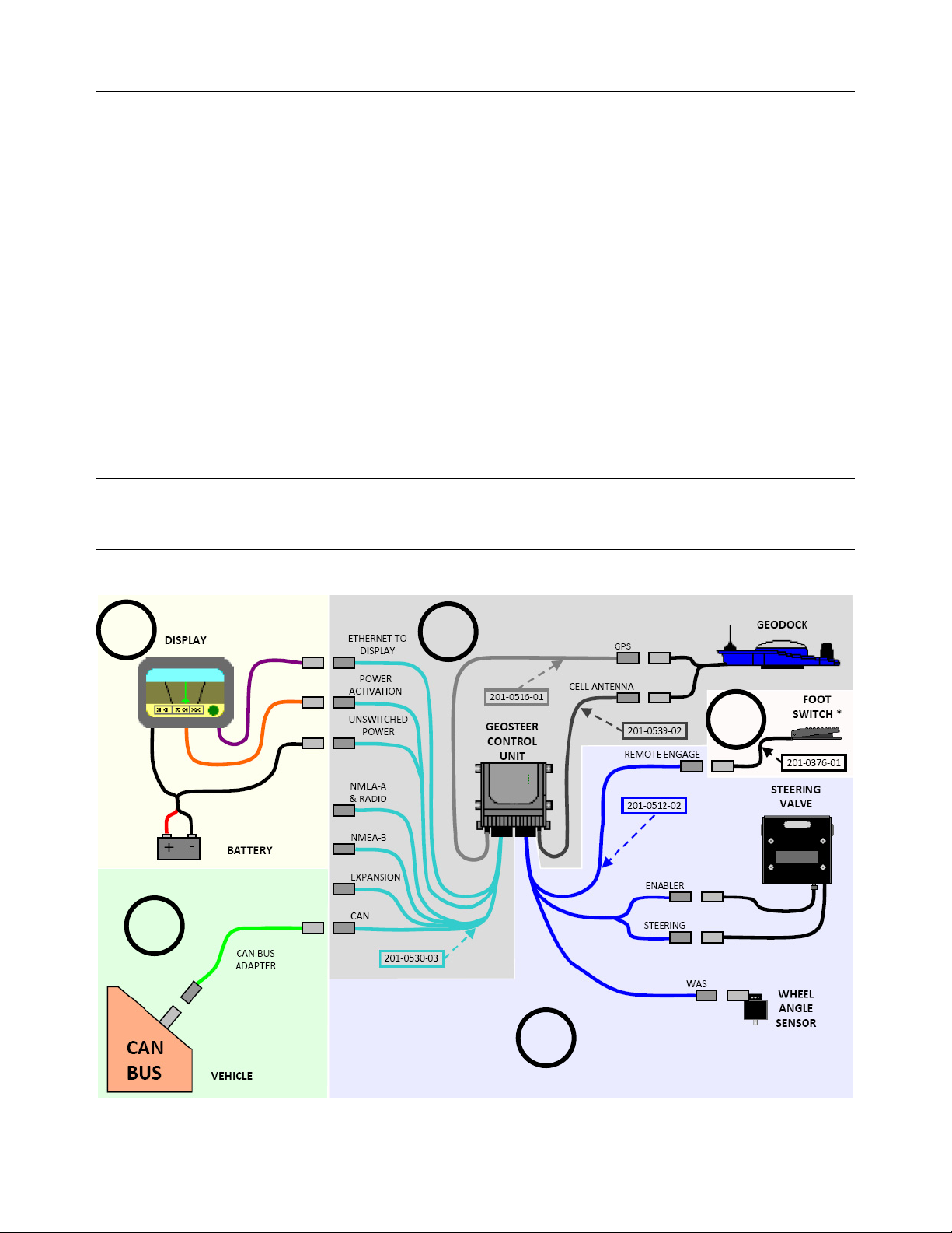
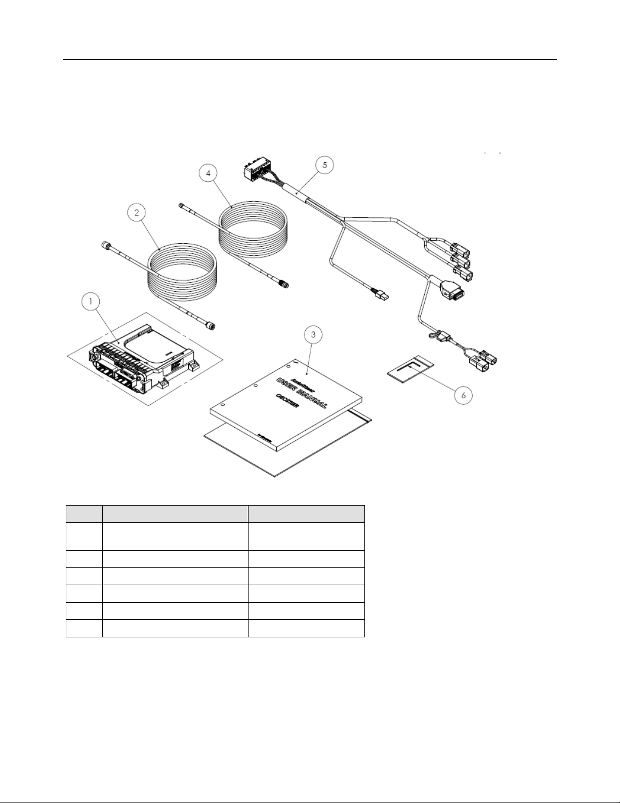
GeoSteer System Installation Overview
GeoSteer System Installation Overview
This section provides an overview of what is required to complete a GeoSteer system installation. To aid in clarifying the
complete installation, this section also includes the parts and kits that are not included with this vehicle installation kit. A
GeoSteer system installation can be broken down into four sub-categories that need to be ordered to complete the installation.
Three of the sub-categories are mandatory and the fourth is a list of accessories that add additional features and capabilities.
The four parts or sub-categories of a complete GeoSteer system installation are:
1. Display Kit
2. GeoSteer System Kit
3. Vehicle Installation Kit
a. Hydraulic, Steer by Wire, or Assisted Steering Unit
b. CAN Bus
4. Accessory Kit
Each of the sub-categories is graphically shown in the following figure and is identified by a separately shaded area and the
number from the list above. Most installations will be slightly different and required different parts.
Note: Vehicle installation kits will generally include parts from only either sub-category 3a or 3b. The following figure shows
examples of how both 3a and 3b components would be connected to the GeoSteer system for demonstration purposes. Most
installations would not require both.
Figure 1-1 Example of GeoSteer Installations Options
1
2
3b
4
3a
2 GeoSteer System
Page 17

GeoSteer System Installation Overview
There are a number of options available for each sub-category. Each of these options comes with their own installation and
operational manuals that should be referred to during their part of the installation.
1 Display Kits
GeoSteer is compatible with multiple Display options. The Displays are ordered as a separate component and include their own
installation and operator’s instructions. The Display Operator’s Manual will show how the Display and Display Harnesses are
installed on a vehicle and how they are connected to the GeoSteer Harnesses. There are three connections between the Display
and the GeoSteer Main Cable Harness that need to be connected:
•
ETHERNET TO DISPLAY – This connection is a RJ-45 connector that is plugged into the Ethernet port on the Display
or Display Harness to provide communications between the Display and the GeoSteer Control Unit.
•
POWER ACTIVATION – This connection is connected to the Display or Display Harness that provides a signal that
commands the GeoSteer to power up. When this signal is turned off, the GeoSteer will power down.
•
UNSWITCHED POWER – This is connected to a power source that provides 12 volts of unswitched DC power to the
GeoSteer. The power source should not be connected to a power supply that is connected to the vehicle’s ignition. This
source should be shown or explained in the Display Operator’s Manual.
The Display Kit will provide the necessary harnesses and instructions to provide power to the GeoSteer system and to allow
communications between the two. Use those instructions to complete the Display installation and to connect the Display to the
GeoSteer system after the Display mount has been installed.
2 GeoSteer System Kits
The GeoSteer System Kits represent the parts that are common on all installations. The GeoSteer System kits are ordered as
two parts, the System Kits and the GeoDock (GPS and Cell Modem Antenna assembly).
The System Kits include a version of the GeoSteer Control Unit, the GeoSteer Main Harness, User’s Manual, a version of the
GeoDock, GPS coax cable, and when required, the Cell Modem coax cable. There are four base versions of this kit that are
sold in different parts of the world. The listed regions are for reference only and can change over time. They System Kits are:
Note: Refer to your AutoSteer dealer for exact part numbers.
•
GeoSteer CDMA – North America
•
GeoSteer No Cell – Australia and South America
•
GeoSteer GSM Europe – Europe
•
GeoSteer GSM Australia – Australia
There are two GeoDock versions that can be ordered. The one that is ordered depends on if the GeoSteer System Kit requires a
Cell Modem or not. The two GeoDock Kits are:
•
GeoDock Pro – This GeoDock assembly has a built in Cell Modem antenna installed.
•
GeoDock Pro – No Cell – This GeoDock assembly is the same as the GeoDock Pro except the cell antenna and coax cable
are not provided.
Operator’s Manual 3
Page 18

GeoSteer System Installation Overview
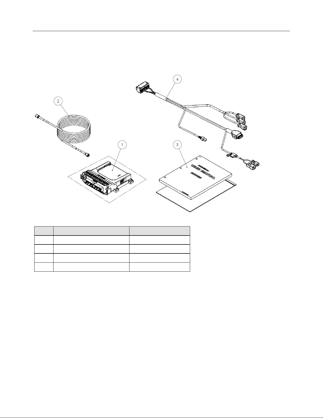
GeoSteer CDMA
This version is used primarily in North America. It has a CDMA modem installed in the GeoSteer control unit that can be used
for remote diagnostics and NTRIP correction services.
Figure 1-2 GeoSteer CDMA
Table 1-1 GeoSteer CDMA Breakdown
Item Component Part Number
1.
2.
3.
4.
5.
GeoSteer Assembly - CDMA 200-0601-XX
Cable, GPS Coax 201-0516-01
Kit Documentation 200-0593-03
Cable, Cell Modem Coax 201-0539-02
Harness, Main GeoSteer 201-0530-03
4 GeoSteer System
Page 19
GeoSteer System Installation Overview
GeoSteer No Cell
This version is used primarily in South America and can be ordered as an option in Australia. There is no cell modem installed
inside the GeoSteer control unit.
Figure 1-3 GeoSteer Cell Free
Table 1-2 GeoSteer Cell Free Breakdown
Item Component Part Number
1.
2.
3.
4.
GeoSteer Assembly - No Cell 200-0617-XX
Cable, GPS Coax 201-0516-01
Kit Documentation 200-0593-03
Harness, Main GeoSteer 201-0530-03
Operator’s Manual 5
Page 20
GeoSteer System Installation Overview
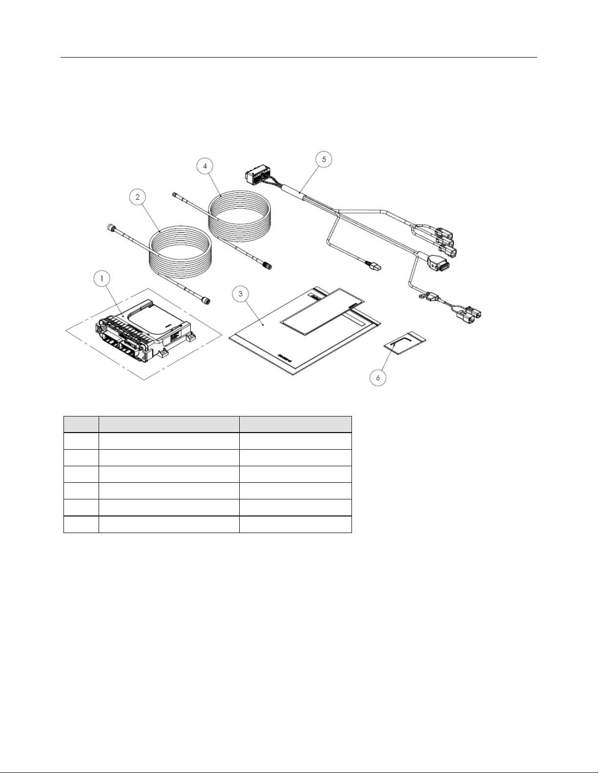
GeoSteer GSM Europe
This version is used primarily in Europe. It has a GSM modem configured to work in the European Union installed in the
GeoSteer control unit that can be used for remote diagnostics and NTRIP correction services. The GeoSteer control unit has a
SIM card slot that allows the user to easily change SIM cards for a custom data plan if necessary.
Figure 1-4 GeoSteer GSM Europe
Table 1-3 GeoSteer GSM Europe Breakdown
Item Component Part Number
1.
2.
3.
4.
5.
6.
GeoSteer Assembly - GSM Europe 200-0618-XX
Cable, GPS Coax 201-0516-01
Kit Documentation 200-0593-05
Cable, Cell Modem Coax 201-0539-02
Harness, Main GeoSteer 201-0530-03
Allen Key, 2mm 805-0006-01
6 GeoSteer System
Page 21
GeoSteer System Installation Overview
GeoSteer GSM Australia
This version is used primarily in Australia. It has a GSM modem configured to work in Australia installed in the GeoSteer
control unit that can be used for remote diagnostics and NTRIP correction services. The GeoSteer control unit has a SIM card
slot that allows the user to easily change SIM cards for a custom data plan if necessary.
Figure 1-5 GeoSteer GSM Australia
Table 1-4 GeoSteer GSM Australia Breakdown
Item Component Part Number
1.
2.
3.
4.
5.
6.
GeoSteer Assembly - GSM
Australia
Cable, GPS Coax 201-0516-01
Kit Documentation 200-0593-03
Cable, Cell Modem Coax 201-0539-02
Harness, Main GeoSteer 201-0530-03
Allen Key, 2mm 805-0006-01
Operator’s Manual 7
200-0619-XX
Page 22
GeoSteer System Installation Overview
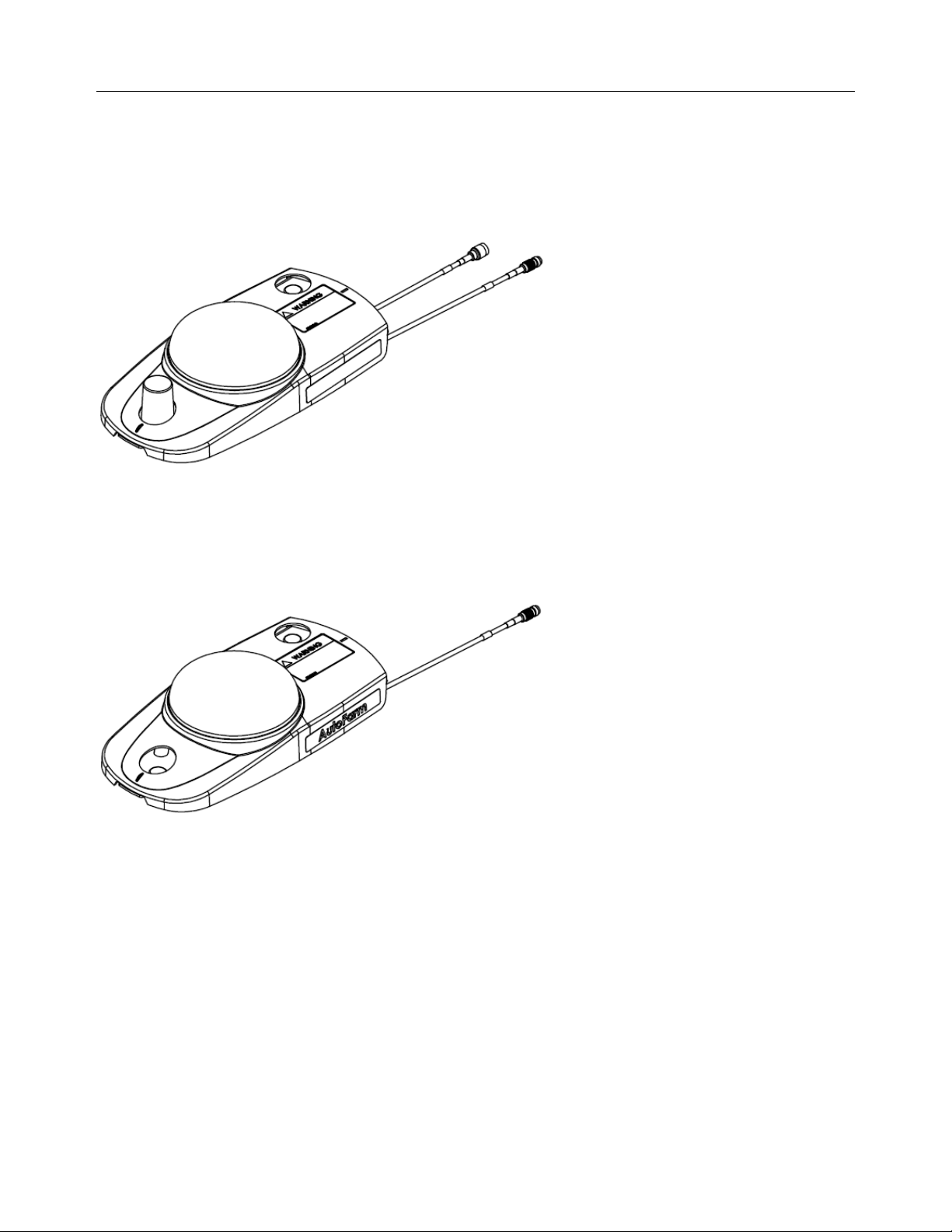
GeoDock Pro
The GeoDock Pro is the roof mounted piece of the GeoSteer system that contains the GPS Antenna and Cell Modem antenna.
The GeoDock Pro houses the optional GS-900 or GS-450 Radio Modems or the GS-OmniSTAR Demodulator when they are
installed.
Figure 1-6 GeoDock Pro
GeoDock Pro – No Cell
This version of GeoDock is the same as the GeoDock Pro except the assembly does not have a Cell Modem Antenna or coax
connector installed on it. This version is ordered with kits that do not come with a Cell Modem.
Figure 1-7 GeoDock Pro - No Cell
3 Vehicle Installation Kits
The GeoSteer system is designed to be compatible with many makes and models of vehicles available in today’s agricultural
market. GeoSteer is brand neutral and can be installed on any manufacturer’s vehicle including AGCO, Ag Chem, Case,
Challenger, Fendt, John Deere, New Holland, Massey Ferguson, and many others. The GeoSteer system is also capable of
being installed on a variety of platforms including articulated tractors, combines, MFWD and standard front axle tractors,
floaters, sprayers, swathers, track tractors, and others. The same user interface can be used on all vehicles, regardless of the
make or model, making it easy for drivers to become familiar with the controls even if the system is installed on multiple
vehicle types.
To make installations simple and reliable, many vehicle-specific installation kits have been designed to fit on each individual
make and model. These kits are available for vehicles that come from the factory with a factory installed steering system (ex.
Steer Ready, CAN Bus, or ISO Ready) as well as options for those vehicles that need a complete steering kit installed. Even if
there is not a vehicle-specific kit available for the vehicle, properly trained installers can often use a custom installation kit to
8 GeoSteer System
Page 23

Accessing AutoSteer Setup Screens
connect the GeoSteer system to the vehicle. Specific instructions for the vehicle installation kits are provided with the
installation kits. Refer to those instructions when installing the vehicle kit.
Note: The list of supported vehicle-specific kits is always being expanded. Contact your AutoSteer dealer for the latest list of
vehicle-specific installation kits to see if the vehicle being installed on has a released kit.
4 Accessory Kits
The GeoSteer system is compatible with optional accessory kits that can be ordered and installed to provide additional features
and capabilities. The primarily reason to install an accessory kit is to provide a radio modem link with a Base Station or an
OmniSTAR demodulator for OmniSTAR corrections. These accessories are not required for all installations and some are not
available in all locations. Order only the kits that are required to provide the accuracy level and communication needs required
for the installation. The accessory kits available at the time of this writing are:
•
GS-900NA (PN 200-0652-01) – 900 MHz radio modem for North America
•
GS-900AU (PN 200-0652-02) – 900 MHz radio modem for Australia
•
GS-OmniSTAR (PN 200-0653-01) – OmniSTAR demodulator for world
•
GS-410 (PN 200-0667-03) – 406-430 MHz radio modem for world
•
GS-430 (PN 200-0667-02) – 430-450 MHz radio modem for world
•
GS-450 (PN 200-0667-01) – 450-470 MHz radio modem for world
•
Remote Engage Foot Switch (PN 200-0458-01) – Remote Engage foot switch that can be attached to the GeoSteer Main
Harness to allow the user to start and stop AutoSteer with a foot switch
Note: The list of accessory kits is always being expanded. Contact your AutoSteer dealer for the latest list of accessory kits.
Specific installation instructions for each accessory kit are provided with the kits themselves. Refer to those instructions when
installing the accessory kits
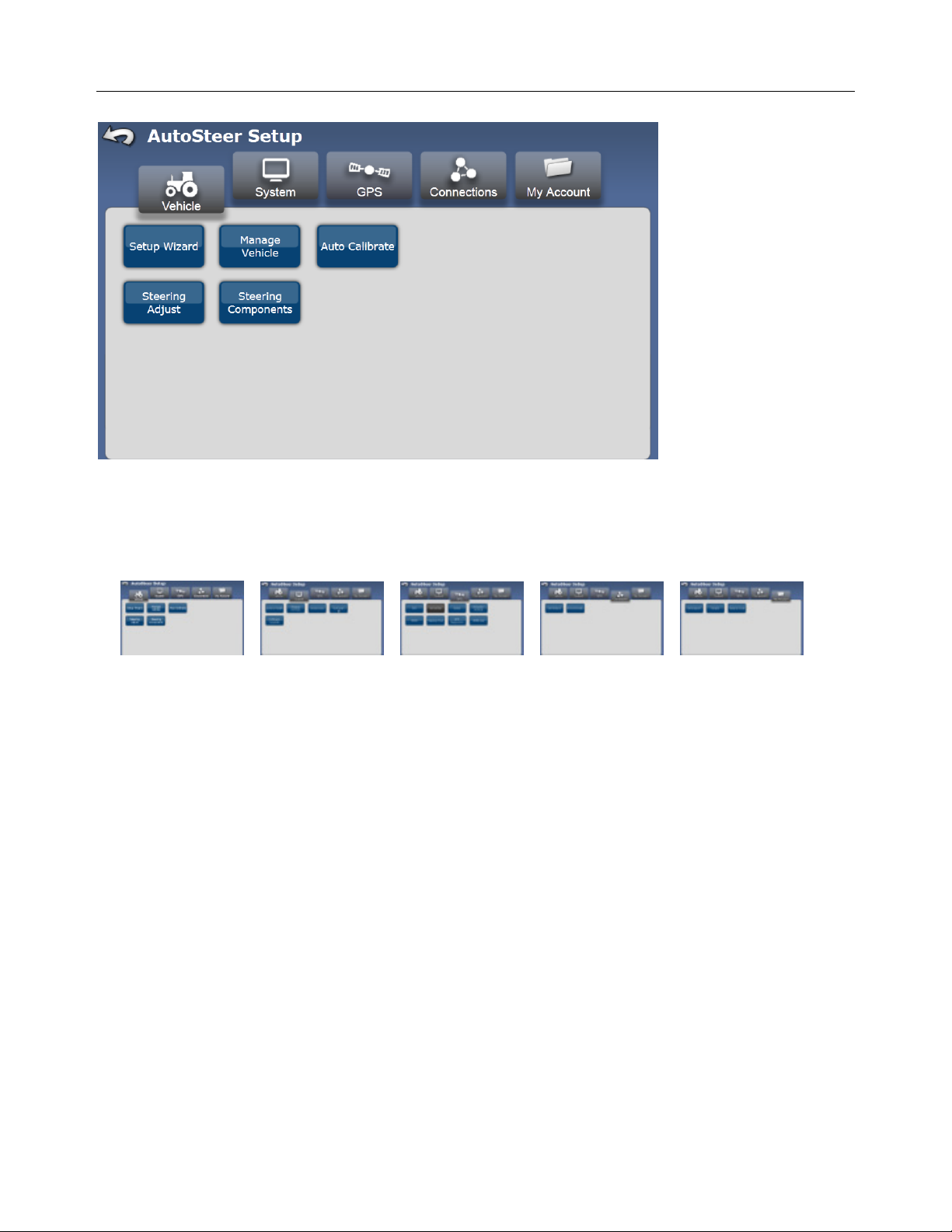
Accessing AutoSteer Setup Screens
The GeoSteer system adds GPS positioning and vehicle steering control to compliment the features of your Display. The
settings, configuration options, and monitoring features for the GPS and vehicle communications are kept separate from the
Display controls. To access them in a GeoSteer system navigate to the AutoSteer Setup screens from the Display. If changes
need to be made to the GPS functionality or to move the system to a different vehicle profile, the user will need to manage
those options in the AutoSteer Setup screen.
Your Display Operator’s Manual will provide instructions on navigating to the AutoSteer Setup page. Please refer to that
document for those instructions. Figure 1-1 shows the AutoSteer Setup opening screen when it is first accessed from the
Display.
Operator’s Manual 9
Page 24
Transferring GeoSteer from Vehicle to Vehicle
Figure 1-8 AutoSteer Setup Opening Screen
The five folder tabs along the top of the screen separate the GeoSteer configuration and monitoring functions into sub groups
to simplify management. The five tabs and the options for each are shown below:
VEHICLE SYSTEM GPS CONNECTIONS MY ACCOUNT
Setup Wizard System Health RTK Cell Modem Call Support
Manage Vehicles Manage Settings OmniSTAR External Radio Details
Auto Calibrate Accessories WAAS/EGNOS Feature Code
Steering Adjust Technician Precision Settings
Steering Components Software Upgrade NTRIP
Planning Tools
GPS Diagnostics
NMEA Out
Each of these tabs is described in detail in the following chapters. For more information about each feature shown above, refer
to the corresponding chapter.
Transferring GeoSteer from Vehicle to Vehicle
The GeoSteer system is designed to be easily transferred from vehicle to vehicle. Specific vehicle kits are available that can be
installed on each vehicle so that only the Display, GeoSteer Control Unit, and GeoDock need to be transferred from vehicle to
vehicle. Each vehicle that the GeoSteer system is to be transferred to should have the Display Harness, Power Harnesses,
Vehicle Harnesses, and GeoDock Harnesses already preinstalled. Contact your AutoSteer dealer for information about
obtaining and installing additional vehicle specific kits. Use the instructions in the section to transfer the GeoSteer system from
one vehicle to another.
10 GeoSteer System
Page 25
Transferring GeoSteer from Vehicle to Vehicle
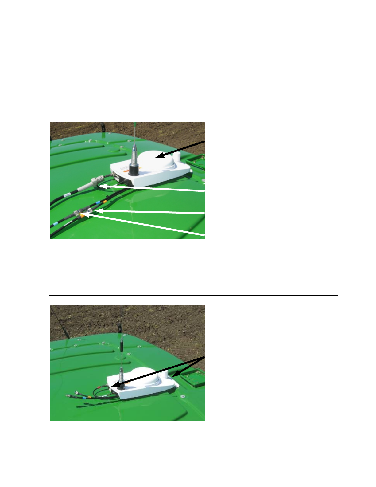
Removing the GeoSteer System from a Vehicle
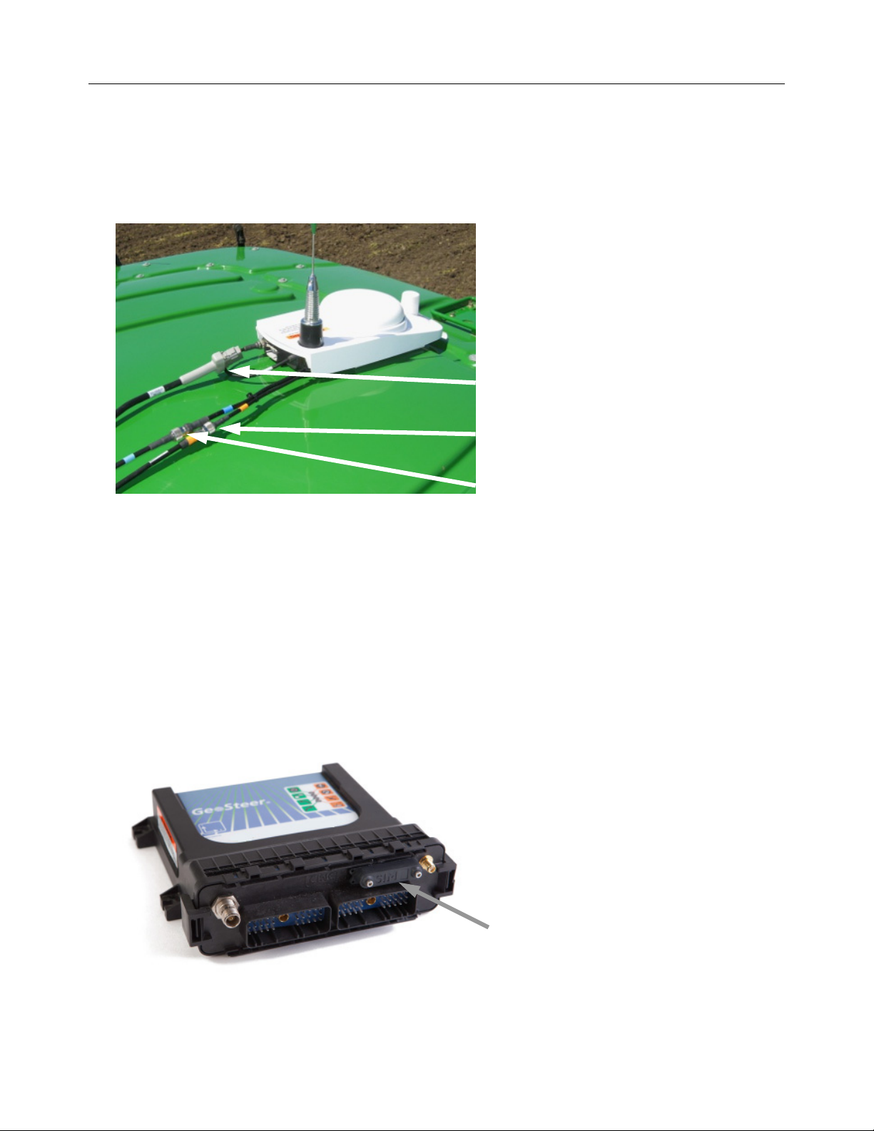
1. Locate the GeoDock on the roof of the vehicle.
2. Disconnect the GPS Coax (Blue) by splitting the TNC Connectors shown.
3. If the GeoDock has a Cell Modem Antenna, disconnect the Cell Modem Antenna Coax (Orange) by splitting the TNC
Connectors shown.
4. If the GeoDock has an optional GS-900, GS-450, or GS-OmniSTAR Demodulator, disconnect the 12-pin Power/Data
Connector shown.
Figure 1-9 Locate GeoDock and GeoDock Connections
GeoDock
Optional GS-900, GS-450, or GS-OmniSTAR
Demodulator Power/Data Connector
Cell Modem Connector (Orange) (if Applicable)
GPS Coax Connector (Blue)
5. Secure the cable connections left on the cab of the vehicle and protect them from dirt/moisture.
6. Carefully pry the magnetically attached GeoDock from the GeoDock Mounting Bracket.
Note: Only pry up on the GeoDock from the metal lip on the front or back of the GeoDock. Never pry the GeoDock using
the plastic cover or by pulling on the coax cables coming out of the back. This can damage the unit.
Pry up from these Points Only
Operator’s Manual 11
Page 26
Transferring GeoSteer from Vehicle to Vehicle
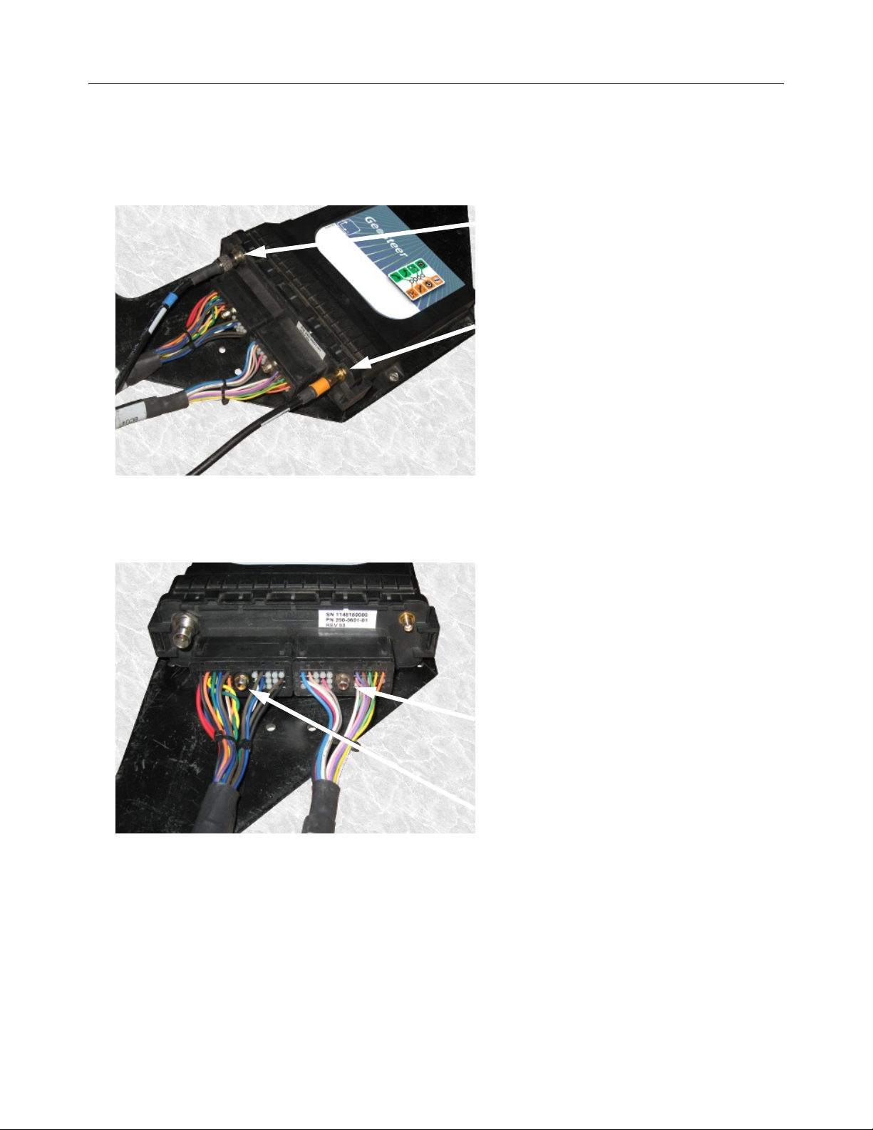
7. Locate the GeoSteer Control Unit on the vehicle.
8. Disconnect the GPS Coax (Blue) TNC Connector from the GeoSteer Control Unit.
9. If the GeoDock has a Cell Modem connection, disconnect the Cell Modem (Orange) SMA Connector from the GeoSteer
Unit.
Figure 1-10 Locate GeoSteer Control Unit on Vehicle
TNC GPS Coax (Blue) Connector
SMA Cell Modem Coax (Orange) Connector (if
equipped
10. Use a 1/4 inch nut driver to remove the GeoSteer Main Cable Harness connector from the GeoSteer Control Unit.
11. Use a 1/4 inch nut driver to remove the Vehicle Specific Cable Harness (if present) from the GeoSteer Control Unit.
Figure 1-11 Disconnect GeoSteer Control Unit Harnesses
Vehicle Specific Cable Harness Connector
(if Installed)
GeoSteer Main Cable Harness Connector
12 GeoSteer System
Page 27
Transferring GeoSteer from Vehicle to Vehicle
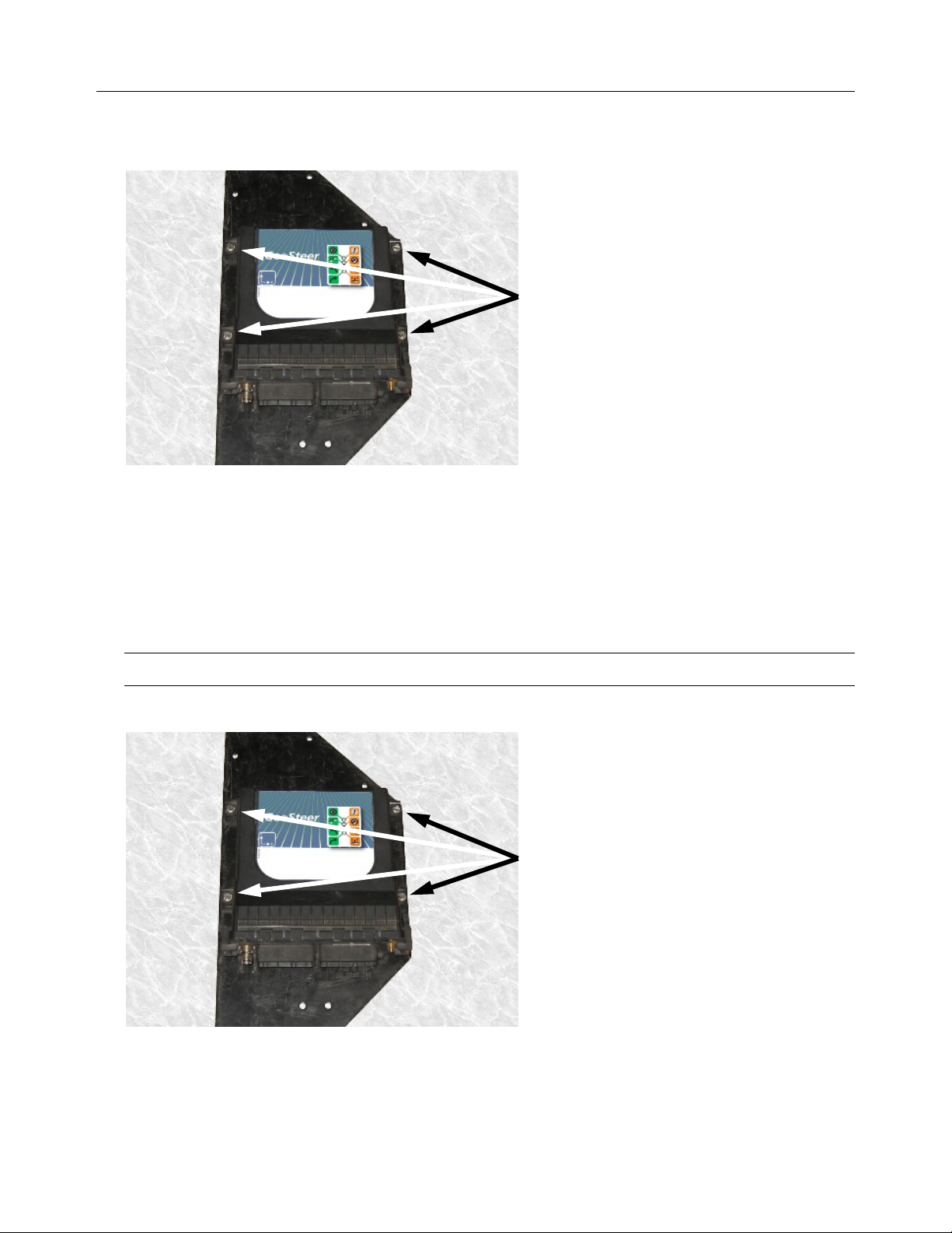
12. Remove the four 8-32 x 1/2 Hex Screws using a 1/4 inch nut driver. This releases the GeoSteer Control Unit from the
vehicle mounting bracket so it can be moved to another vehicle.
Figure 1-12 Remove Screws Holding GeoSteer Control Unit
Remove the Four Screws
13. Remove the Display from the cab using the instructions provided in the Display Operator’s Manual.
Installing the GeoSteer System on to Vehicle
1. Install the Display in the cab using the instructions provided in the Display Operator’s Manual.
2. Attach the GeoSteer Control Unit to the mounting bracket with four 8-32 x 1/2 Hex Screws. Tighten the screws using a
1/4 inch nut driver.
Note: Do not over tighten the screws.
Figure 1-13 Attach GeoSteer Control Unit with Screws
Attach GeoSteer Control Unit with Four Screws
Operator’s Manual 13
Page 28
Transferring GeoSteer from Vehicle to Vehicle
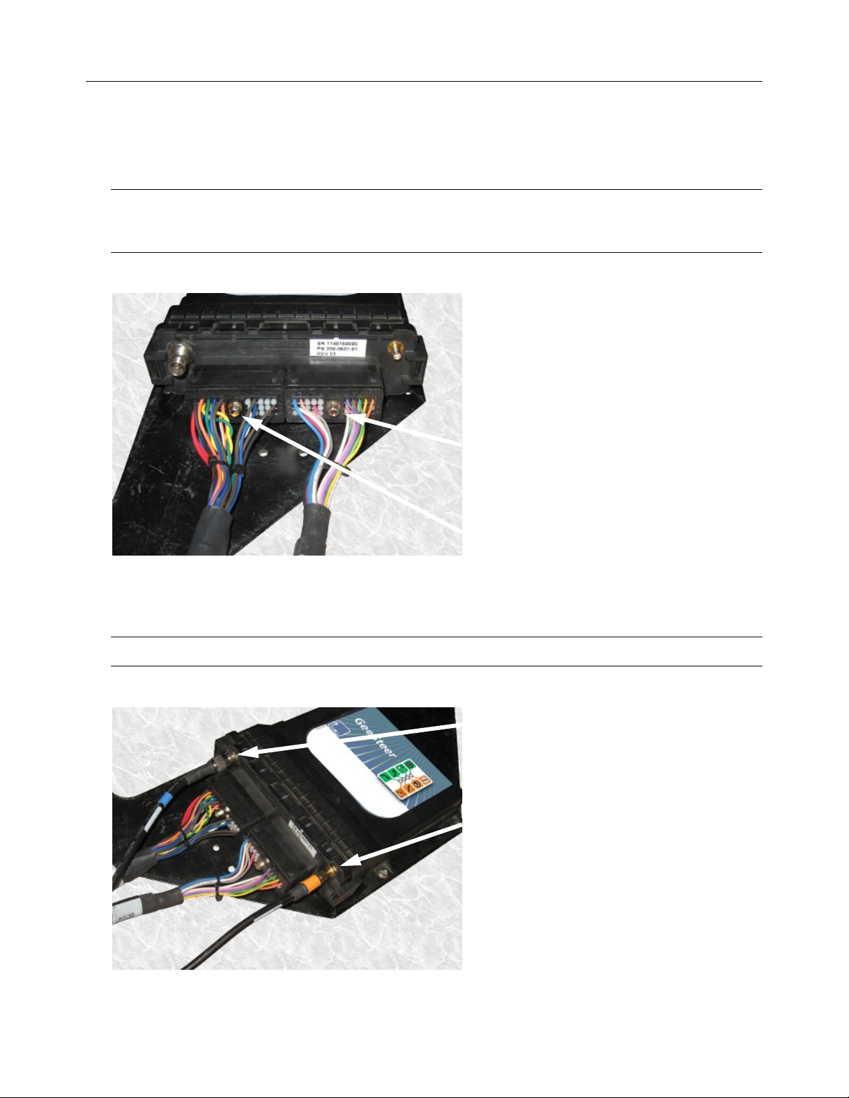
3. Attach the GeoSteer Main Cable Harness connector to the left side connector on the GeoSteer Control Unit. Match the
Yellow dots on the harness to the GeoSteer Control Unit Connector. Use a 1/4 inch nut driver to tighten the connector.
4. Attach the Vehicle Specific Cable Harness (if required) to the right side connector on the GeoSteer Control Unit. Match
the White dots on the harness to the GeoSteer Control Unit Connector. Use a 1/4 inch nut driver to tighten the connectors.
Note: Both connectors are keyed so they will only attach the proper side of the GeoSteer Control Unit and in one
orientation. The connectors should slide easily onto the receptacle. If they do not slide easily, try a different position. Do
not force the connector into the receptacle as this could damage the connectors.
Figure 1-14 Attach GeoSteer Control Unit Harnesses
Vehicle Specific Cable Harness Connector
(if Required)
GeoSteer Main Cable Harness Connector
5. Attach the GPS Coax (Blue) TNC Connector to the GeoSteer Control Unit.
6. If the GeoDock has a Cell Modem connection, attach the Cell Modem (Orange) SMA Connector from the GeoSteer Unit.
Note: Hand tighten the Coax connectors only. Do not use a tool to tighten as this may damage the connectors.
Figure 1-15 Attach Coax Connectors
TNC GPS Coax (Blue) Connector
SMA Cell Modem Coax (Orange) Connector (if
equipped
14 GeoSteer System
Page 29
Transferring GeoSteer from Vehicle to Vehicle
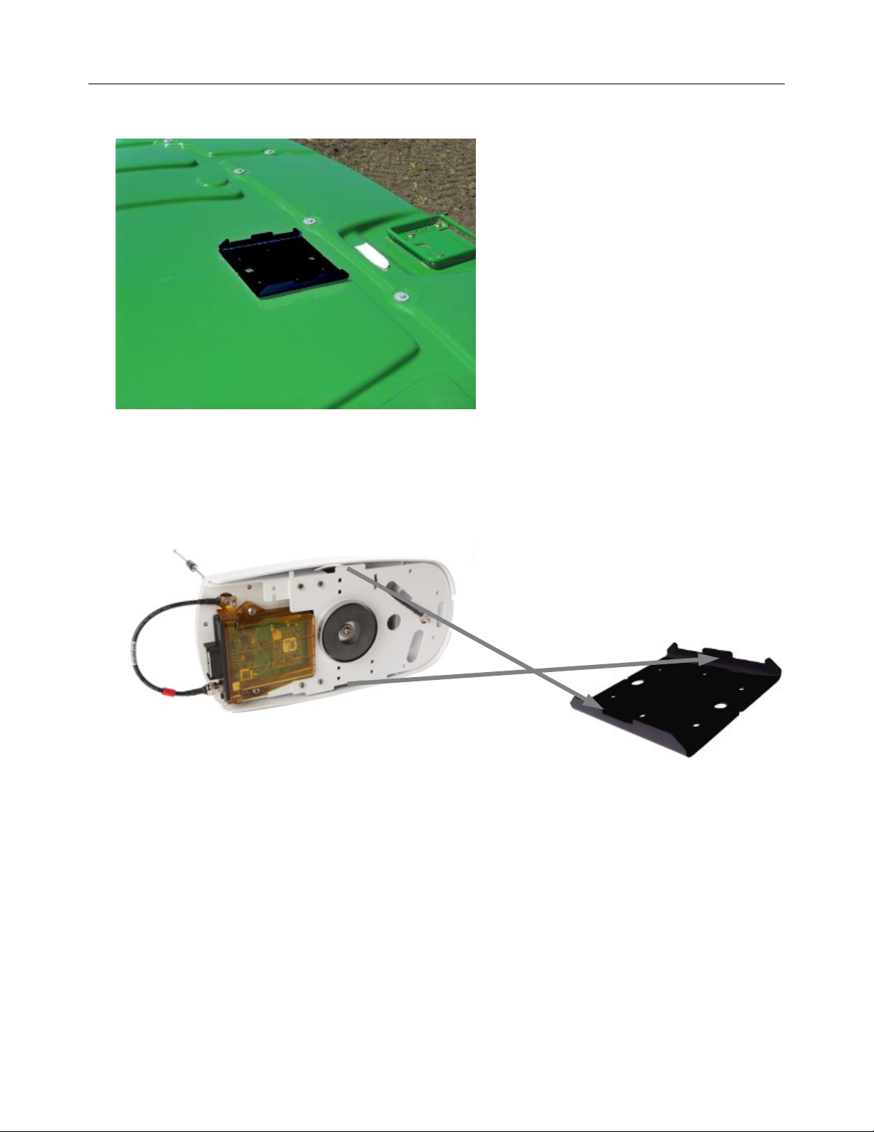
7. Locate the GeoDock Mounting Plate on top of the cab.
Figure 1-16 GeoDock Mounting Plate
8. Attach the GeoDock to the mounting plate taking care to match the mounting tabs on the GeoDock with the tabs on the
mounting plate.
Figure 1-17 Match Tabs on GeoDock to Mounting Plate
Operator’s Manual 15
Page 30
Changing SIM Card in GeoSteer
9. Attach the GPS Coax (Blue) TNC Connector to the connector on the GeoDock.
10. If the GeoDock has a Cell Modem Antenna, attach the Cell Modem Antenna Coax (Orange) TNC Connector to the
connector on the GeoDock.
11. If the GeoDock has an optional GS-900, GS-450, or GS-OmniSTAR Demodulator, connect the 12-pin Power/Data
Connector to the back of the radio modem or demodulator.
Figure 1-18 Locate GeoDock and GeoDock Connections
Optional GS-900, GS-450, or GS-OmniSTAR
Demodulator Power/Data Connector
Cell Modem Connector (Orange) (if Applicable)
GPS Coax Connector (Blue)
12. Power up the GeoSteer system and navigate to the AutoSteer Setup screen. Use the Manage Vehicles button to select the
activate the vehicle that the GeoSteer system has been installed on. Refer to the Manage Vehicle section on Page 45 for
information on setting the active vehicle.
Changing SIM Card in GeoSteer
The GSM Cell Modem versions of the GeoSteer Control Unit have an external SIM card slot that allows the user to change the
SIM card for NTRIP usage. This SIM slot is not found on CDMA Cell Modem versions of the GeoSteer Control Unit. This
section provides the instructions to change the SIM card if that becomes necessary.
1. Locate the SIM Card slot on the cable connector side of the GeoSteer Control Unit.
Figure 1-19 SIM Card Slot
16 GeoSteer System
SIM Card Slot
Page 31

Changing SIM Card in GeoSteer
2. Loosen the two screws holding the SIM Card slot cover on with a 2mm Allan wrench supplied with the GeoSteer System
and remove the cover. The screws stay attached to the cover.
Figure 1-20 Remove Cover by Loosening Screws
Remove Screws
3. The edge of the SIM Card will be visible. Gently push the SIM card into the slot and then release. The SIM Card should
pop out of the slot.
Note: The SIM Card cover has a flat blade that can be used to assist in pressing the SIM Card in so it will release.
Figure 1-21 Remove SIM Card
Press SIM Card in
4. Verify that the area around the SIM Card slot and the SIM Card cover are clean. If necessary clean with a damp cloth and
allow it to dry before reassembling.
5. Insert the new SIM Card into the slot.
Note: The SIM Card cover shows how the notch on the SIM card needs to be orientated when inserting into the slot.
Verify the SIM card is orientated properly before inserting.
Operator’s Manual 17
Page 32

Changing SIM Card in GeoSteer
Note: Never force the SIM Card into the slot. It should slide easily in. If it does not verify that it is orientated correctly.
6. Replace the SIM Card cover to protect it. Tighten the two screws with a 2mm Allan wrench.
7. Power up the GeoSteer system and navigate to the AutoSteer Setup page. Configure the SIM card following the procedure
provided in the Configure SIM section on Page 135.
18 GeoSteer System
Page 33

GeoSteer Control Unit LED Diagnostics
GeoSteer Control Unit LED Diagnostics
The GeoSteer Control Unit has been designed with four LEDs that can be used to help determine the status of the GeoSteer
system as well as provide some basic troubleshooting information. Figure 1-22 shows the front panel of the GeoSteer Control
Unit. The LEDs will be off, Green, or Amber.
Figure 1-22 Front Panel of GeoSteer Control Unit
Use Table 1-5 for the definitions of the different LEDs and colors.
Table 1-5 GeoSteer Icon Definitions
Green
Icons
Description
Solid Green – Indicates good power.
No Color – No power to the GeoSteer Control
Unit.
Flashing Green – Indicates communication with
the Display.
No Color – No communication with Display.
Green – GeoSteer Control Unit is commanding
actuator to turn left.
No Color – No output being commanded.
Green – GeoSteer Control Unit is commanding
actuator to turn right.
No Color – No output being commanded.
Amber
Icons
Description
Flashing Amber – Voltage problem detected in
the GeoSteer Control Unit.
Solid or Flashing Amber – System is loading
new firmware to the GeoSteer Control Unit.
Note: Do not cut off power to the GeoSteer
Control Unit while this light is amber.
Flashing Amber – Displays the number of
satellites being tracked.
Note: The number of quick amber flashes
indicates the number of satellites. Restart
counting after the long pause.
Flashing Amber – Indicates the GeoSteer
Control Unit is receiving a RTK correction
signal via Radio Modem.
Operator’s Manual 19
Page 34

Page 35

Vehicle Tab
The Vehicle Tab chapter contains information in the following sections:
•
Overview
•
Setup Wizard
•
Manage Vehicle
•
Auto Calibrate
•
Steering Adjust
•
Steering Components
Overview
2
Figure 2-1 AutoSteer Setup Vehicle Tab
The Vehicle menu enables the user to configure a new vehicle, manage existing vehicles, perform an auto calibration of a
vehicle, make steering adjustments and manage steering components. This menu allows the user to configure and monitor the
various components related to the vehicle interface with the GeoSteer Control Unit.
To access the Vehicle menu, refer to your Display Operator’s Manual for instructions on accessing the AutoSteer Setup
screens. The Vehicle menu will be the first one that is displayed when the AutoSteer Setup screen is accessed.
Each of the following menu options are explained in detail in this chapter.
Operator’s Manual 21
Page 36

Setup Wizard
•
Setup Wizard – Walks the user through setting up a new vehicle.
•
Manage Vehicle – Allows the user to select, edit, delete, or export/import vehicle profiles into the GeoSteer system.
•
Auto Calibrate – Allows user to start or restart a vehicle calibration for the current vehicle.
•
Steering Adjust – Allows user to make adjustments to steering response, line acquisition, heading aggressiveness, and
reverse response
•
Steering Components – Provides status screens and set some values for all the components that are connected to the
vehicle. This includes CAN communication, steering kick out information, Wheel Angle Sensor readings, Steering Valve
control, Remote Engage detection, etc.
Setup Wizard
The Setup Wizard is a step-by-step guide that leads the user thru the procedure required to create a new vehicle profile. The
Setup Wizard procedure will change depending on what type of vehicle is selected and/or what options are installed on the
GeoSteer System. This manual will describe all possible options that GeoSteer may come equipped with. Not all screens
described in this manual will be displayed for all vehicle setups. To setup a new vehicle profile, press the Setup Wizard button
from the AutoSteer Setup Vehicle tab. Depending on the conditions the Setup Wizard will begin at one of the following points:
•
Additional Steps for the First Time the Setup Wizard is Run – The wizard will start here only when the Setup Wizard is
run the first time from the factory or the first time after the system has been reset to factory defaults.
•
Standard Setup Wizard Steps – The wizard will start here almost every time and will jump to here after the Additional
Steps for the First Time the Setup Wizard is completed the first time.
Additional Steps for the First Time the Setup Wizard is Run
The first time the system is powered up from factory or after the database is reset to factory default, the first time a vehicle is
created additional steps are added at the beginning of the Setup Wizard. These steps tell the system how to configure the
various GPS correction and radio options. If the settings for these steps are unknown at the time of the initial vehicle setup,
they can be changed later via their respective configuration menus. This manual will show all possible steps that could be
displayed; however, the actual system will only show the steps for the devices that it detects during the actual Setup Wizard. If
a radio or OmniSTAR demodulator is not detected, those steps will be skipped.
To start the Setup Wizard, press the Setup Wizard button from the AutoSteer Setup Vehicle tab. The following steps may be
encountered during the initial setup depending on how the system is configured:
WAAS/EGNOS Setup
If the system is powered up in a location where the system determines a WAAS or EGNOS signal should be available, the
following screen will appear. The WAAS or EGNOS correction signal is transmitted from geostationary satellites. Each of
these satellites has a unique numerical name called its PRN. The GeoSteer system needs to be told which PRN (or satellite) to
listen to for the correction information.
Note: The system must have a clear view of the sky and the GPS antenna must be connected in order for the system to
determine its location and time.
Note: If the system is powered up in an area where EGNOS is available, the system will ask for EGNOS PRN values.
22 GeoSteer System
Page 37

Setup Wizard
Figure 2-2 WAAS/EGNOS Initial Setup Screen
The GeoSteer system can detect and simultaneously track two separate WAAS or EGNOS PRNs. If the Primary PRN becomes
unavailable, the system will automatically switch to the Secondary PRN. To change either of the PRNs to a different satellite,
press the Change Primary or Change Alternate button. Refer to the WAAS or EGNOS websites to determine satellite
availability and health for your location.
Use the keypad shown in Figure 2-3 to enter the Primary or Secondary WAAS/EGNOS PRN number. After the PRN has been
set press the Green Check Mark button to save the setting. Press the Red X button to cancel.
Figure 2-3 PRN Number Change
After both PRN values have been set, press the Blue Right Arrow button shown in Figure 2-2 to continue to the next step.
Operator’s Manual 23
Page 38

Setup Wizard
Set RTK Radio Modem Channel or Frequency
If the GeoSteer detects a GS-900 or GS-450 Radio Modem, the user will be prompted to enter a channel or frequency to match
the channel or frequency of the transmitting Base Station. Press the Change Frequency or Change Channel button to set this
value.
Figure 2-4 Set RTK Radio Modem Channel or Frequency
Use the keypad shown in Figure 2-5 to enter the channel or frequency used on the Base Station. After the channel has been set
press the Green Check Mark button to save the setting. Press the Red X button to cancel.
Figure 2-5 Change Radio Channel or Frequency
After the channel or frequency has been set, press the Blue Right Arrow button shown in Figure 2-4 to continue to the next
step.
24 GeoSteer System
Page 39

Setup Wizard
Set OmniSTAR Options
If the GeoSteer detects an OmniSTAR Demodulator, the user will be prompted to enter a channel to match their location.
OmniSTAR has different satellite feeds depending on the GeoSteer system geographic location. Press the Change Channel
button to set this value.
Figure 2-6 OmniSTAR Setup
The OmniSTAR Channel Selection screen will display all the current OmniSTAR channels that are available. Select the
channel for your region and press the Green Check button to save that selection. Press the Red X button to cancel.
Note: For more information on configuring the OmniSTAR signal refer to OmniSTAR section on Page 103.
Figure 2-7 OmniSTAR Channel Selection List
The OmniSTAR Setup screen, shown in Figure 2-6 also allows the user to choose the initial startup accuracy. When the
GeoSteer is started, it takes time for the OmniSTAR signal to converge to the accuracy level provided by OmniSTAR. Some
users may not require the full accuracy of the OmniSTAR correction for the job being performed. If this is the case, some users
may choose to start before the system fully converges. The GeoSteer system allows the user to choose:
•
Fast Startup – The GeoSteer will allow the system to begin AutoSteering before it fully converges. This allows the user to
start AutoSteering sooner. Select this setting if accuracy is not as important at the initial startup as getting running quickly.
The system will continue to converge in the background and become more accurate the longer the system runs and will
eventually reach full convergence.
•
High Accuracy – The GeoSteer will not allow the system to begin AutoSteering until it has reached full convergence. The
system will take longer to allow AutoSteer operations. Select this option if accuracy is important at the initial startup.
Operator’s Manual 25
Page 40

Setup Wizard
After the channel and startup accuracy have been selected, press the Blue Right Arrow button shown in Figure 2-6 to continue
to the next step.
Precision Preference Selection
GeoSteer is designed to allow the user flexibility in selecting the accuracy level the system operates at. Depending on the
GeoSteer Feature Codes that have been unlocked, the geographic location, OmniSTAR Demodulator that may be installed, the
user can choose from Autonomous Pass-to-Pass all the way up to RTK. In RTK and OmniSTAR modes, the system also allows
the accuracy to “Flex” back to WAAS/EGNOS or Autonomous Pass-to-Pass when the RTK or OmniSTAR signal is lost for a
short time. To choose the accuracy level that GeoSteer will operate at, press the Change Mode button shown in Figure 2-8.
Figure 2-8 Set Precision Preference
The list of Available Precision Settings will display. This list will depend on which features have been unlocked, whether the
system detects an OmniSTAR Demodulator, and the geographic location the system believes it is located. Not all options will
be available to all users. Select the Precision Setting that the system will operate with and then press the Green Check button to
save that selection. Press the Red X button to cancel.
Figure 2-9 Available Precision Settings
Each of the selections has specific accuracy levels and operational requirements. An explanation of each setting is provided
below:
Note: “Flex” is a term that denotes the system switching from one accuracy level to another when a correction source is lost. In
most cases, this happens when the RTK data link between the Base Station and the GeoSteer is interrupted. This could happen
due to radio or cell communication loss or an obstacle between the GeoSteer and the communication source (ex. Base Station
Radio Modem or Cell Tower). “Flex” will not help if the GPS signals from the satellites are blocked by obstacles such as trees
or buildings.
26 GeoSteer System
Page 41

Setup Wizard
•
RTK Only – This mode is only displayed if the RTK Feature Code has been unlocked on the GeoSteer. The system must
have a RTK source from a Base Station via a Radio Modem or from a NTRIP source via the Cell Modem. If selected, the
GeoSteer assumes the user must be 99.9% sure of position. It requires a RTK link at all times and will disengage
AutoSteering if the link is lost. This setting expects good satellite geometry and low PDOP. Because of the high accuracy
expectation, the chances that degraded conditions occur and stop AutoSteering is higher. Use only when high accuracy is
needed at all times.
•
Flex High Accuracy (0-10 cm) – (0 to 3.9 inches) This mode is only displayed if the RTK Feature Code has been
unlocked on the GeoSteer. The system must have a RTK source from a Base Station or NTRIP stream. While receiving a
RTK signal, the system is just as accurate as RTK Only mode. However, this mode allows the system to lose the RTK data
link from the Base Station for a short time and allow the vehicle to continue to AutoSteering. When the RTK signal is lost,
the system will “Flex” back to WAAS/EGNOS or Autonomous Pass-to-Pass until the estimated error gets above 10 cm.
The amount of time allowed in flex mode depends on GPS conditions. The operator is warned when the system has entered
“Flex” mode and can decide if they wish to continue or wait for the RTK link to be reestablished.
•
Flex Low Accuracy (0-30 cm) – (0 to 11.8 inches) This mode is only displayed if the RTK Feature Code has been
unlocked on the GeoSteer. This mode the same as Flex High Accuracy (0-10 cm) except the system will “flex” until the
estimated error gets above 30 cm. This will allow a longer period of operation with out a RTK signal, but it is possible the
system will have more position error the longer it does not have the RTK signal. However, as long as the RTK signal is
present, the system will be just as accurate as RTK Only. The operator is warned when the system has entered “Flex”
mode and can decide if they wish to continue or wait for the RTK link to be reestablished.
•
OmniSTAR Only – This mode is only displayed if the GeoSteer detects that an OmniSTAR Demodulator has been
installed on the GeoDock. The system will use the OmniSTAR for corrections only and will not “flex” to any other mode if
the signal is lost. GeoSteer supports the OmniSTAR XP and HP signals only.
•
OmniSTAR Flex to WAAS/EGNOS/Autonomous Mode – This mode is displayed only if the GeoSteer detects that an
OmniSTAR Demodulator has been installed on the GeoDock. If the system is running in OmniSTAR mode, the user has
the option to “Flex” back to WAAS, EGNOS, or Autonomous Mode if the OmniSTAR signal is lost for some reason. The
mode the system will “Flex” to will depend on which region the GeoSteer is located. WAAS and EGNOIS are available in
North America and Europe respectively. Autonomous Mode is available for the rest of the world. Once the OmniSTAR
signal has been required, the system will return back to OmniSTAR mode.
•
WAAS/EGNOS Only – This mode is only available where WAAS or EGNOS are available. The GeoSteer will only use
the WAAS/EGNOS signal for corrections even if an OmniSTAR or RTK signal is available.
•
Autonomous Pass-to-Pass – This mode is only available in areas where WAAS or EGNOS are not available. The
GeoSteer will use the GPS signals themselves to calculate reduce the error of the position. This mode allows the system to
run with no correction sources.
After the Precision Preference has been selected, press the Blue Right Arrow button shown in Figure 2-8 to continue to the
next step.
Standard Setup Wizard Steps
If this is not the first time the Setup Wizard was run from the factory or after a reset to factory defaults, The Setup Wizard will
begin here. The Setup Wizard will take the user through each step required to setup a new vehicle. The actual steps and screen
shots may change depending on the vehicle type that is selected and the control options that are available for that vehicle.
Note: When the Setup Wizard button is pressed, the Setup Wizard will always start at this point except for the very first time
the button is pressed after the system is started the first time from the factory or after the system has been reset to factory
defaults.
Operator’s Manual 27
Page 42

Setup Wizard
Select Vehicle Type
The Vehicle Type represents the type of vehicle the GeoSteer is installed on. The various vehicle types generally have different
control parameters and measurement points. This setting allows the system to determine which options will be presented to the
user in later steps. Press the Gray Up and Down arrows or directly select the vehicle type.
Figure 2-10 Vehicle Type
The following vehicle types can be chosen from:
•
•
•
•
•
•
•
Articulated –Large four wheel drive vehicles that steer by articulating in the center of the vehicle are
in this group. This group includes Quadtrac vehicles.
Combine – Grain harvesting and forage harvesting machines where the rear axle is used to steer the
vehicle are in this group.
Floater – Three and four wheeled vehicles with large floatation tires used to spread fertilizer or
chemicals on broad acres at high speeds are in this group.
MFWD – Standard tractors with the steering axle on the front of the machine are in this group.
Sprayer – High clearance self propelled sprayers with spray booms are in this group.
Swather – Swathers and self propelled mowers are in this group.
Track – Vehicles that have tracks are in this group.
After the Vehicle Type has been selected, press the Blue Right Arrow button shown in Figure 2-10 to continue to the next step.
28 GeoSteer System
Page 43

Setup Wizard
Select Vehicle Make
The Vehicle Make represents the manufacturer of the vehicle. The vehicle manufacturers that have Vehicle Specific GeoSteer
Installation Kits available are shown in this list. Press the Gray Up and Down arrows or directly select the appropriate Vehicle
Make from the list.
Note: If the vehicle manufacturer is not listed on this screen, select Generic from the list. This allows you to create a vehicle
that does not have a factory supported installation kit.
Figure 2-11 Vehicle Make
After the Vehicle Make has been selected, press the Blue Right Arrow button to continue to the next step.
Select Vehicle Model
The Vehicle Model represents the model of the vehicle. In most cases if the model has a Vehicle Specific GeoSteer Installation
Kit available, the model will be shown in the list. Press the Gray Up and Down arrows or directly select the appropriate
Vehicle Model from the list.
Note: If the vehicle model is not listed on this screen, you can select a model that is similar to the one that is being installed on
or go back to the Vehicle Make screen and select Generic from the list. This allows you to create a vehicle and model that does
not have a factory supported installation kit.
Figure 2-12 Vehicle Model
Operator’s Manual 29
Page 44

Setup Wizard
After Vehicle Model has been selected, press the Blue Right Arrow button to continue to the next step.
Select Controller Type
The Controller Type represents the controller the GeoSteer will be interfaced with in order to steer the vehicle. GeoSteer can be
interfaced with a number of controller options including the standard AutoSteer valves, OnTrac2+, as well as a number of
factory installed steering systems. Press the Gray Up and Down arrows or directly select the appropriate Controller Type from
the list.
Note: The screen shot in Figure 2-13 shows the possibilities for one particular make and model. The list of options will change
depending on what Vehicle Type, Make, and Model are selected in the previous steps.
Figure 2-13 Controller Type
The possible Controller Types that may display are:
•
Standard – Hydraulic – This is an AutoSteer steering valve that was installed on the vehicle with the Vehicle Specific
Installation kit. This valve is not a factory installed option.
•
OnTrac2
•
AccuGuide Ready
•
Auto-Guide2
2
– This is an OnTrac2, OnTrac2+, or other mechanically steered controller.
3
– This represents a factory installed steering system used by CaseIH.
4
– This is used to communicate to the ISO Bus of vehicles under the AGCO manufacturing umbrella.
Vehicle makes in this group include AGCO, Challenger, Fendt, Gleaner, Massey Ferguson, and others using the same ISO
Bus communications hardware.
•
AutoTrac Ready
5
– This represents a factory installed steering system used by John Deere if the GeoSteer is being
connected directly to the sensors and valves on the vehicle.
•
AutoTrac Ready ISO – This represents a factory installed steering system used by John Deere if the GeoSteer is being
connected directly to the ISO Bus on the vehicle and not being connected to the individual sensors and valve.
•
Vehicle – CAN This is used for vehicles that use a standard ISO Bus interface such as for Challenger Track and
Articulated vehicles and Krone to interface directly with the vehicles CAN Bus.
•
IntelliSteer Ready
6
- This represents a factory installed steering system used by New Holland.
After the Controller Type has been selected, press the Blue Right Arrow button to continue to the next step
2
This is a registered trademark of Novariant
3
This is a registered trademark of CNH
4
This is a registered trademark of the AGCO Corporation
5
This is a registered trademark of John Deere Company
6
This is a registered trademark of CNH
30 GeoSteer System
Page 45

Setup Wizard
Naming the Vehicle
The Vehicle Name screen allows the user to enter a custom name for the vehicle. This name is independent of the name
provided on the Display side of the vehicle setup. You cannot use the same name twice in GeoSteer system. Use the on screen
keyboard to type in the name of the vehicle.
Figure 2-14 Vehicle Name
Special keys on the keyboard:
•
BACK ARROW – This is the delete key.
•
UP ARROW – This is the shift key. Use this to type in capital letters.
•
abc (ABC) – This activates and shows the letters on the keyboard.
•
123 – This activates and shows the numbers on the keyboard.
•
+@# - This activates and shows the special characters that can be used to name the vehicle.
After the Vehicle Name has been entered, press the Blue Right Arrow button to continue to the next step
Wheel Base
This measurement is only required for vehicles with two axles, the GeoSteer system needs to know the distance between the
front and rear axle. This distance is the vehicle’s Wheel Base. Use a tape measure to measure the distance between the two
axles and then enter that value into the Display.
Note: Always measure both sides of the vehicle and use the average of the two measurements.
Note: The units of measure shown in the AutoSteer Setup pages are configured on the Display side and passed to the GeoSteer
menus. Refer to your Display Operator’s Manual for instructions on how to set the units of measure.
Note: Be sure to verify that the measurement entered is in the same units that the display is expecting. The expected unit of
measurement is shown to the right of the data input box.
Note: This measurement should be accurate to within 2 inch (5.0 cm).
Operator’s Manual 31
Page 46

Setup Wizard
Figure 2-15 Vehicle Wheel Base
After the Wheel Base has been entered, press the Blue Right Arrow button to continue to the next step
Antenna Fore/Aft
The Antenna Fore/Aft measurement is the distance the GeoDock GPS antenna is attached to the vehicle as compared to the
Pivot Point of the vehicle. The Pivot Point of the vehicle is the place where the vehicle rotates around as it turns left or right.
The location of the Pivot Point is different depending on what vehicle type is being installed on. Common Pivot Points for
most vehicles are:
•
Front Axle Steering – The Pivot Point is at the rear axle for MFWD, SPRAYER, FLOATER vehicle
profiles.
•
Track Vehicle – The Pivot Point is at the center point of the track.
•
Articulated Vehicles – The Pivot Point is at the articulation joint of the vehicle.
•
Rear Axle Steering – The Pivot Point is at the front axle for COMBINE and SWATHER vehicle
profiles.
First identify the Pivot Point on the vehicle that the GeoSteer is being installed on. Take a tape measure and measure the
distance between the Pivot Point and the GPS antenna on the GeoDock. Enter that value into the Antenna Fore/Aft window.
Note: Be sure to verify that the measurement entered is in the same units that the display is expecting. The expected unit of
measurement is shown to the right of the data input box.
Note: The units of measure shown in the AutoSteer Setup pages are configured on the Display side and passed to the GeoSteer
menus. Refer to your Display Operator’s Manual for instructions on how to set the units of measure.
32 GeoSteer System
Page 47

Setup Wizard
Note: This measurement should be accurate to within 1 inch (2.5 cm).
Figure 2-16 Antenna Fore/Aft
The GPS antenna can be mounted in front or behind the Pivot Point. Press the button that indicates which side of the Pivot
Point the GPS antenna is mounted. If the value is 0.0, it does not matter which button is pressed.
•
Fore – This indicates the GPS antenna is located in front of the vehicle’s Pivot Point.
•
Aft – This indicates the GPS antenna is located behind the vehicle’s Pivot Point.
After Antenna Fore/Aft has been entered, press the Blue Right Arrow button to continue to the next step
Antenna Lateral Offset
The Antenna Lateral Offset is the distance from the center of the drawbar to the GPS antenna. This value should be 0.0 if the
GeoDock is mounted in the center of the vehicle. If the GeoDock is not mounted in the center, measure this offset and enter it
into this screen. This value will be adjusted later after the calibration process is complete to ensure the center of the vehicle is
in the same position going both directions on the same A/B Line.
Note: If the Antenna Lateral Offset is ever changed by more than 4.0 inches (10.2 cm), a new calibration procedure must be
performed on the vehicle.
Take a tape measure and measure the distance between the center of the vehicle (typically the draw bar) and the GPS antenna
on the GeoDock. Enter that value into the Antenna Lateral Offset window.
Note: Be sure to verify that the measurement entered is in the same units that the display is expecting. The expected unit of
measurement is shown to the right of the data input box.
Note: The units of measure shown in the AutoSteer Setup pages are configured on the Display side and passed to the GeoSteer
menus. Refer to your Display Operator’s Manual for instructions on how to set the units of measure.
Note: This measurement should be accurate to within 1 inch (2.5 cm).
Operator’s Manual 33
Page 48

Setup Wizard
Figure 2-17 Antenna Lateral Offset
For best results, the GeoDock should be mounted along the centerline of the vehicle; however it can be mounted to the left or
right of the centerline if necessary. Press the button that indicates which side of the centerline the GPS antenna is mounted. If
the offset is 0.0, it does not matter which one is selected.
•
Left – This indicates that the GPS is to the left of the centerline.
•
Right – This indicates that the GPS is to the right of the centerline.
After the Antenna Lateral Offset has been entered, press the Blue Right Arrow button to continue to the next step.
Antenna Height
The Antenna Height is the distance from the ground to GPS antenna on the GeoDock as shown in Figure 2-18.
Figure 2-18 Measuring Point on the GeoDock GPS Antenna
Measure to this Point
Take a tape measure and measure the distance from the ground to the GPS antenna on the GeoDock. Enter that value into the
Antenna Height window.
Note: Be sure to verify that the measurement entered is in the same units that the display is expecting. The expected unit of
measurement is shown to the right of the data input box.
Note: The units of measure shown in the AutoSteer Setup pages are configured on the Display side and passed to the GeoSteer
menus. Refer to your Display Operator’s Manual for instructions on how to set the units of measure.
Note: This measurement should be accurate to within 2 inches (5.0 cm).
34 GeoSteer System
Page 49

Setup Wizard
Figure 2-19 Antenna Height
After the Antenna Height has been entered, press the Blue Right Arrow button to continue to the next step.
GeoSteer Fore/Aft
Just like the GPS antenna, the location of the GeoSteer Control Unit must be entered into the system. These measurements are
important for GeoSteer to achieve its rated performance. All measurements entered into the GeoSteer system should be
measured to the center point of the GeoSteer Control Unit box at the top surface.
Note: The bull’s eye shown in Figure 2-20 is not on the actual GeoSteer Control Unit label. It is shown here only to show the
approximate location of the measurement point on the GeoSteer Control Unit.
Figure 2-20 Measurement Point on GeoSteer Control Unit
Measure to this Point
Operator’s Manual 35
Page 50

Setup Wizard
The GeoSteer Fore/Aft measurement is the distance the GeoSteer Control Unit is attached to the vehicle as compared to the
Pivot Point of the vehicle. The Pivot Point of the vehicle is the same point that was used to enter the Antenna Fore/Aft. For an
explanation of the location of the Pivot Point on the vehicle refer to the Antenna Fore/Aft section on Page 32. First identify the
Pivot Point on the vehicle that the GeoSteer is being installed on. Take a tape measure and measure the distance between the
Pivot Point and the center point of the GeoSteer Control Unit shown in Figure 2-20. Enter that value into the GeoSteer
Fore/Aft window.
Note: Be sure to verify that the measurement entered is in the same units that the display is expecting. The expected unit of
measurement is shown to the right of the data input box.
Note: The units of measure shown in the AutoSteer Setup pages are configured on the Display side and passed to the GeoSteer
menus. Refer to your Display Operator’s Manual for instructions on how to set the units of measure.
Note: This measurement should be accurate to within 1 inch (2.5 cm).
Figure 2-21 GeoSteer For/Aft
The GeoSteer Control Unit can be mounted in front or behind the Pivot Point. Press the button that indicates which side of the
Pivot Point the GPS antenna is mounted. If the value is 0.0, it does not matter which button is pressed.
•
Fore – This indicates the GeoSteer Control Unit is located in front of the vehicle’s Pivot Point.
•
Aft – This indicates the GeoSteer Control Unit is located behind the vehicle’s Pivot Point.
After GeoSteer Fore/Aft has been entered, press the Blue Right Arrow button to continue to the next step.
GeoSteer Lateral Offset
The GeoSteer Lateral Offset is the distance from the center of the drawbar the center point of the GeoSteer Control Unit shown
in Figure 2-20. Unlike the Antenna Lateral Offset, This value should not be adjusted once entered unless it’s later determined
to be incorrect. Take a tape measure and measure the distance between the center of the vehicle (typically the draw bar) and the
GeoSteer Control Unit. Enter that value into the GeoSteer Lateral Offset window.
Note: Be sure to verify that the measurement entered is in the same units that the display is expecting. The expected unit of
measurement is shown to the right of the data input box.
36 GeoSteer System
Page 51

Setup Wizard
Note: The units of measure shown in the AutoSteer Setup pages are configured on the Display side and passed to the GeoSteer
menus. Refer to your Display Operator’s Manual for instructions on how to set the units of measure.
Note: This measurement should be accurate to within 1 inch (2.5 cm).
Figure 2-22 GeoSteer Lateral Offset
The GeoSteer Control Unit can be mounted to the left or right side of the centerline. Press the button that indicates which side
of the centerline the GPS antenna is mounted. If the offset is 0.0, it does not matter which one is selected.
•
Left – This indicates that the GeoSteer Control Unit is to the left of the centerline.
•
Right – This indicates that the GeoSteer Control Unit is to the right of the centerline.
After GeoSteer Lateral Offset has been entered, press the Blue Right Arrow button to continue to the next step.
GeoSteer Height
The GeoSteer Height is the distance from the ground to the center of GeoSteer Control Unit as shown in Figure 2-20. Take a
tape measure and measure the distance from the ground to the GeoSteer Control Unit. Enter that value into the GeoSteer
Height window.
Note: Be sure to verify that the measurement entered is in the same units that the display is expecting. The expected unit of
measurement is shown to the right of the data input box.
Note: The units of measure shown in the AutoSteer Setup pages are configured on the Display side and passed to the GeoSteer
menus. Refer to your Display Operator’s Manual for instructions on how to set the units of measure.
Note: This measurement should be accurate to within 1 inch (2.5 cm).
Operator’s Manual 37
Page 52

Setup Wizard
Figure 2-23 GeoSteer Height
After the GeoSteer Height has been entered, press the Green Check button to continue to the next step.
GeoSteer Orientation
The GeoSteer Control Unit needs to know which orientation it is mounted in or the system will not work properly. If the
GeoSteer Control Unit has been installed according to the Vehicle Specific Installation Instructions, the orientation will already
be shown on the GeoSteer GCU Orientation screen as shown in Figure 2-24. A graphic showing how the GeoSteer Control
Unit is installed compared to the orientation of the vehicle is shown on the left. The view will always be as if the user is
looking down from the top of the cab with the front of the vehicle pointing to the top of the screen.
Note: A small tractor icon showing a tractor from above will be shown in all graphics to help the user visualize how the
GeoSteer Control Unit should be installed on the vehicle.
Figure 2-24 GeoSteer Orientation
If the default position shown matches the actual mounting position of the installation, press the Green Check Mark button to
continue to the next step.
If the default orientation does not match your installation there are two options:
•
Get Orientation – Use this button if the GeoSteer Control Unit is not in the orientation shown in the diagram and the
GeoSteer Control Unit is mounted orthogonally on the vehicle. This means that the GeoSteer Control Unit is at a 90 degree
angle or some multiple of 90 (0, 90, 180, 270) degrees at all three axes (vertically, horizontally, and perpendicular to the
other two) when compared to the direction of travel of the vehicle.
38 GeoSteer System
Page 53

Setup Wizard
•
Enter Angles – Use this button if the GeoSteer Control Unit is not in the orientation shown and it is not mounted
orthogonally. This is only used when custom angles must be entered. Contact your AutoSteer Dealer for assistance in
entering the correct angles.
For more information on how to use the Get Orientation and Enter Angles screens for entering custom orientations of the
GeoSteer Control Unit, refer to one of the corresponding sub-sections.
Get Orientation
When the Get Orientation button is pressed, the system is expecting that the GeoSteer Control Unit is installed at one of the 24
possible orthogonal orientations. To simplify the selection, the GeoSteer will use the built in sensors to detect which way
gravity is pulling on the GeoSteer Control Unit. This allows the GeoSteer to narrow the choice of orientations down to four.
Note: If the GeoSteer Control Unit is not mounted orthogonally and this choice is used, the system will not be able to properly
show the correct orientation. If an orientation is selected that is not exactly the way it is mounted on the vehicle, steering
performance will be poor or not possible.
Figure 2-25 GeoSteer Get Orientation
The following options are available in the Get Orientation screen:
•
•
Enter Angles
When the Enter Angles button is pressed, the system will show a warning screen about how important it is to enter the values
accurately.
Note: Only properly trained technicians should use this option. The angles need to be precisely measured and calculated to
allow the GeoSteer system to work properly. Entering incorrect values will cause the system to perform poorly. Always
attempt to attach the GeoSteer Control Unit orthogonally if possible. Always contact your AutoSteer Dealer for assistance in
entering the correct angles.
Cycle View – This button cycles through the four possible orientations that are detected by the GeoSteer Control
Unit. Press this button until the figure on the left side of the screen shows the GeoSteer Control Unit in the same
orientation as it is installed in the vehicle. When the correct orientation is found, press the Green Check button to
save the orientation and to continue to the next step.
Start Over – If none of the orientations match, press this button to return the settings back to the default position. This
will return the screen back to the one shown in Figure 2-24.
Operator’s Manual 39
Page 54

Setup Wizard
Figure 2-26 GeoSteer Warning
Press the Green Check button only if the angles have been provided by your AutoSteer Dealership. If the angles are not
known, press the Red X button.
Once the Warning screen has been accepted, the GeoSteer expects the user to enter custom angles to tell the system how the
GeoSteer Control Unit is mounted on the vehicle. These angles must be accurate. There are three angles that need to be
entered.
•
(X) Pitch – This is the front to back rotation of the GeoSteer Control Unit as compared to the vehicle.
•
(Y) Roll – This is the side to side rotation of the GeoSteer Control Unit as compared to the vehicle.
•
(Z) Yaw – This is the rotation of the GeoSteer Control Unit compared to the vehicle looking down from the top.
Figure 2-27 GeoSteer Enter Angles
To determine the angles to enter, start with a GeoSteer Control Unit with a rotational settings of (X=0, Y=0, Z=0). This
orientation is with the GeoSteer Control Unit upside down with the connectors pointing to the left side of the vehicle. This is
the Base Orientation Position which all rotations need to be measured from.
Note: Figure 2-28 shows the GeoSteer Control Unit upside down with the connectors pointing to the right side of the vehicle.
This is the Base Orientation that all angle measurements are measured from. The X and Y arrows are not printed on this side of
the GeoSteer Control Unit and are shown only as a reference.
40 GeoSteer System
Page 55

Setup Wizard
Figure 2-28 Base Orientation Position with (X=0, Y=0, Z=0)
Notice GeoSteer Control Unit Orientation as
Compared to Vehicle Orientation
Adjust the angles for X, Y, and Z so that they tell the GeoSteer system how many degrees it must be rotated from the Base
Orientation Position shown in Figure 2-28 to match the actual orientation on the vehicle. This process should only performed
by someone that has had the proper training. Contact your AutoSteer dealer for support.
Besides entering the angles, you have one other option:
•
Start Over – Press this button to return the settings back to the default position. This will return the screen back to the one
shown in Figure 2-24.
When the correct orientation is entered, press the Green Check button to save the orientation and to continue to the next step.
Save Changes
Once all the measurements have been entered, the system will give you one last opportunity to cancel the vehicle creation or to
finalize the new vehicle.
Figure 2-29 Save Changes
Press the Green Check button to save the new vehicle profile and continue to the next step if the installation has a pressure
transducer. If the vehicle does not have a pressure transducer, the Setup Wizard will automatically start the Auto Calibrate
procedure. Refer to the Auto Calibrate section on Page 53 for more information on these steps. Press the Red X button to
cancel the vehicle creation, discard the vehicle, and take user back to the AutoSteer Setup screen.
Operator’s Manual 41
Page 56

Setup Wizard
Manual Steering Override
If the installation has a pressure transducer installed on the vehicle or the GeoSteer is connected to an OnTrac2+ or other
mechanical steering device, the Setup Wizard will automatically take the user to the Manual Steering Override screen so that it
can be calibrated prior to beginning the Auto Calibrate procedure. Depending on the installation, refer to the proper sub-section
below.
•
Pressure Transducer Installations
•
Mechanical Steering Installation (OnTrac2+)
Pressure Transducer Installations
The pressure transducer is used to measure when the operator is turning the steering wheel. When the operator manually turns
the steering wheel on the vehicle, the GeoSteer system uses the pressure transducer to detect a pressure spike in the steering
circuit. The GeoSteer then disables AutoSteer when this spike is detected.
Note: If the Manual Steering Override is not properly calibrated, the system may not disengage properly when the operator
turns the steering wheel which may cause the operator not to be able to avoid an obstacle. Never operate an AutoSteered
vehicle without the Manual Steering Override properly set.
Figure 2-30 Manual Steering Override Adjustment (Hydraulic)
The following information and controls are available on the Manual Steering Override screen for pressure transducers:
•
Pressure Graph – This graph shows a graphically representation of the current pressure which is the shaded green area
starting from the left side of the graph. The kick out pressure reading is shown on the graph by the triangles on the bottom
and top of the graph.
•
Saved – This is the pressure value that is currently saved as the kick out pressure.
•
Current – This is the current pressure reading coming from the pressure transducer.
•
Minus (-) and Plus (+) Buttons – This increases or decreases the setting for the kick out pressure. Pushing these buttons
will move the two triangles left or right on the graph. Use these buttons to manually adjust the kick out pressure value.
•
Save Limit – If the kick out pressure values are changed from the saved values, you must press this button to save them. If
they are not saved, any changes will be lost when the user leaves this screen.
•
Autocal – This button will take the user to an Auto Calibration wizard for the pressure transducer. This is generally the
best way to set up the Manual Steering Override value. More information on this procedure is provided in this section.
•
Start – Press this button to put the system into an AutoSteer simulation. The Start button will change to a Stop button.
Test the kick out setting by turning the steering wheel. If the GeoSteer system reaches the kick out pressure, the Stop
button will change back to the Start button. Use this procedure to test the GeoSteer and ensure the kick out works properly.
42 GeoSteer System
Page 57

Setup Wizard
Once the Manual Steering Override setting has been set, press the Blue Right Arrow button to continue to the next step. The
Setup Wizard will automatically start the Auto Calibrate procedure. Refer to the Auto Calibrate section on Page 53 for more
information on these steps.
Autocal
Figure 2-31 Manual Steering Override Auto Calibrate Wizard
The Manual Steering Override Auto Calibrate wizard automatically calibrates the manual steering override value. Start driving
the vehicle forward between 2.0 and 5.0 mph (3.2 and 8.0 kph) with the engine RPM at the working level. Press the Blue Right
Arrow to continue.
Figure 2-32 Auto Calibrate Ready to Start
Operator’s Manual 43
Page 58

Setup Wizard
Continue driving and then press the Start button. The vehicle will first appear to do nothing and then later the steering axle will
make a series of quick left and right small turns. Once the auto calibration has completed, the Save Calibration screen will
appear.
Figure 2-33 Save Calibration
Press the Green Check button to save the calibration and continue to the next step. The Setup Wizard will automatically start
the Auto Calibrate procedure. Refer to the Auto Calibrate section on Page 53 for more information on these steps. Press the
Red X button to cancel the calibration, discard the values, and take user back to the Manual Steering Override screen.
Mechanical Steering Installation (OnTrac2+)
In a Mechanical Steering installation the, GeoSteer detects the current draw going to the Mechanical Drive Unit. If the current
gets above the Saved value, the GeoSteer will disengage the clutch and kick out of AutoSteer mode. The current goes up when
the operator grabs the steering wheel and attempts to manually turn the wheel the opposite direction the GeoSteer is
commanding it.
Note: If the Manual Steering Override is not properly calibrated, the system may not disengage properly when the operator
turns the steering wheel which may cause the operator not to be able to avoid an obstacle. Never operate an AutoSteered
vehicle without the Manual Steering Override properly set.
Figure 2-34 Manual Steering Override Adjustment (Mechanical Steering Devices)
44 GeoSteer System
Page 59

Manage Vehicle
The following information and controls are available on the Manual Steering Override screen for Mechanical Steering
Devices:
•
Current Graph – This graph shows a graphically representation of the current reading which is the shaded green area
starting from the left side of the graph. The kick out current is shown on the graph by the triangles on the bottom and top of
the graph.
•
Saved – This is the current value that is currently saved as the kick out current.
•
Current – This is the real time current reading coming from the Mechanical Drive Unit.
•
Minus (-) and Plus (+) Buttons – This increases or decreases the setting for the kick out current. Pushing these buttons will
move the two triangles left or right on the graph. Use these buttons to manually adjust the kick out current value.
•
Save Limit – If the kick out current value is changed from the saved values, you must press this button to save them. If
they are not saved, any changes will be lost when the user leaves this screen.
•
Start – Press this button to put the system into an AutoSteer simulation. The Start button will change to a Stop button.
Test the kick out setting by turning the steering wheel. If the GeoSteer system reaches the kick out current, the Stop button
will change back to the Start button. Use this procedure to test the GeoSteer and ensure the kick out works properly.
Once the Manual Steering Override setting has been set, press the Blue Right Arrow button to continue to the next step. The
Setup Wizard will automatically start the Auto Calibrate procedure. Refer to the Auto Calibrate section on Page 53 for more
information on these steps.
Manage Vehicle
The Manage Vehicles screen allows the user to manage the various vehicle profiles that may be loaded on the GeoSteer system.
The GeoSteer system is designed to be able to be moved from one vehicle to another easily. Each vehicle that it is installed on
can have a new vehicle profile that saves the settings, calibration, and tuning values specific to that vehicle. When the system is
installed on a different vehicle, the user must use the Manage Vehicle screens to activate the proper vehicle profile.
To access the Manage Vehicles menu press the Manage Vehicles button from the AutoSteer Setup screen. The Manage
Vehicles menu is displayed.
Figure 2-35 Manage Vehicles
The Manage Vehicles screen allows the user to do four options. They are:
•
Select – This activates the highlighted vehicle profile.
•
Edit – This allows the user to modify the parameters that were entered during the Setup Wizard process.
•
Delete – This allows the user to delete a vehicle profile that is no longer needed.
•
Export/Import – This allows the user to import or export vehicle profiles to or from other GeoSteer systems.
Select
The vehicle profile that is active on the GeoSteer system is displayed in the Active Vehicle box near the top of the screen. The
Active Vehicle must match the vehicle that the system is installed on for the GeoSteer to control it. A list of vehicle profiles
Operator’s Manual 45
Page 60

Manage Vehicle
stored on the GeoSteer is displayed below the Active Vehicle. If the GeoSteer is moved to a different vehicle, the user must
activate the new vehicle on the GeoSteer.
To select a new vehicle, first use the Up/Down Arrows or directly select the vehicle from the list and highlight it. Next press
the Select button. This will change the vehicle that is displayed in the Active Vehicle box to the one that was highlighted and
reprogram the GeoSteer Control Unit to control that vehicle.
After the Select button has been pressed a message is displayed telling the user the new vehicle is now active.
Figure 2-36 Vehicle is Now Active Notification
Press the Blue Check Mark button to continue and return to the previous menu.
Note: The vehicle profiles used to control the vehicles are stored on the GeoSteer Control Unit. These profiles are independent
of the vehicle profiles loaded on the Display. The vehicle profile must be changed both on the Display as well as the GeoSteer
system in order for it to properly interface with the vehicle.
Edit
The Edit button allows the user to make changes to the highlighted vehicle’s configuration settings. These settings are the same
as the ones entered during the initial Setup Wizard procedure as shown on Figure 2-15 thru Figure 2-29. The only difference
between the Create and the Edit screens are how they are labeled on top of the screen. The Edit Vehicle screens will be labeled
Edit Vehicle as shown in Figure 2-37 instead of Create Vehicle as shown in Figure 2-15.
Figure 2-37 Edit Vehicle Wheel Base
46 GeoSteer System
Page 61

Manage Vehicle
To edit a vehicle, first use the Up/Down Arrows or directly select the vehicle from the list and highlight it. Next press the Edit
button. This will take the user through the Edit Vehicle wizard. Instead of repeating all the information for the Edit Vehicle
screens in this section, please refer back to the Create Vehicle section for specific information on how to measure and enter the
proper information for each configuration option. The user can edit the following parameters:
•
Wheel Base – Refer to the Wheel Base section on Page 31.
•
Antenna Fore/Aft – Refer to the Antenna Fore/Aft section on Page 32.
•
Antenna Lateral Offset – Refer to the Antenna Lateral Offset section on Page 33.
•
Antenna Height – Refer to the GeoSteer Height section on Page 37.
•
GeoSteer Fore/Aft – Refer to the GeoSteer Fore/Aft section on Page 35
•
GeoSteer Lateral Offset – Refer to GeoSteer Lateral Offset section on Page 36.
•
GeoSteer Height – Refer to the GeoSteer Height section on Page 37.
•
GeoSteer Orientation – Refer to the GeoSteer Orientation section on Page 38.
The Edit Vehicle wizard will take the user through each of the above configuration options one at a time from the top of the list
to the end. Press the Blue Right Arrow button to move to the next configuration screen. Press the Left Blue Arrow button to
return to the previous configuration screen. To escape the Edit menu without saving any of the changes, press the Previous
Menu Arrow on the top left corner of screen.
When all the editable options have been cycled thru, the Save Changes dialog box appears
The user must cycle thru all the configuration screens and press the Green Check button in order to save any of the
Note:
changes made. If the user does not do this, the changes will not be saved.
Figure 2-38 Save Changes
Press the Green Check button to save the changes and return to the Manage Vehicle screen. Press the Red X button to return
back to the Edit Vehicle screens.
Delete
The Delete button allows the user to delete the highlighted vehicle profile from the GeoSteer.
To delete a vehicle, first use the Up/Down Arrows or directly select the vehicle from the list and highlight it. Next press the
Delete button. The Confirm Delete Vehicle message will appear.
Note: The Active Vehicle cannot be deleted. First select or create another vehicle and make it active, the go back and delete
the desired vehicle profile.
Operator’s Manual 47
Page 62

Manage Vehicle
Figure 2-39 Confirm Delete Vehicle
Press the Green Check button to delete the vehicle and return to the Manage Vehicle screen. Press the Red X button to cancel
deleting the vehicle and return to the Manage Vehicle screen.
Export/Import Vehicles
The Export/Import button allows the user to import or export vehicle profiles to or from a USB storage device to or from other
GeoSteer systems. Users may have more than one GeoSteer system and multiple vehicles they work on. The GeoSteer system
can also be transferred to multiple vehicles. The Export/Import feature allows the user to easily transfer all the vehicle profiles
to all GeoSteer units in the fleet. This saves time as each vehicle does not have to be set up and calibrated on each GeoSteer.
Importing and exporting vehicles have the following limitations:
1. The GeoSteer you export from and the GeoSteer you import into must be running the same firmware version. For best
results always upgrade all GeoSteers to the latest version prior to importing and exporting vehicles.
2. Only one vehicle can be imported and exported at a time from the Manage Vehicle screen.
Note: Multiple vehicles can be stored on the USB drive at one time, but they can only be saved to the USB or loaded from it
one at a time.
If there are multiple vehicles with the same name on different GeoSteers, copying vehicle profiles from one GeoSteers to the
next may overwrite the data. Each vehicle must have a unique name so the data is kept separate when copying vehicles from
GeoSteer to GeoSteer.
For example if a customer has three JD8430 vehicles, each JD8430 must have a different name such as JD8430 1, JD8430 2,
and JD8430 3. This limitation needs to be considered prior to creating a vehicle as the name of the vehicle in the GeoSteer
cannot be changed after it has been created. To rename the vehicle, the user must create a new vehicle with the desired name
and recalibrate it.
To import or export a vehicle profile, press the Export/Import button. This opens the Export/Import Management screen.
48 GeoSteer System
Page 63

Manage Vehicle
Figure 2-40 Export/Import Manage Management Screen
The Export/Import Management window gives the user the following options:
•
Blue Back Arrow – Pressing this button returns the user to the Manage Vehicles screen.
•
Export to Display USB – Pressing this button will start the process of exporting the selected vehicle profile to the USB on
the Display.
•
Import from Display USB – Pressing this button will start the process of importing a vehicle profile from the USB drive
on the Display
Export to Display USB
To export profiles to a USB storage device, follow the procedure in this section.
1. Insert a USB disk into the USB drive on the Display.
2. Select the vehicle profile that is to be exported by using the Up/Down Arrows or directly selecting the vehicle from the
list on the top part of the screen and highlight it
3. Press the Export to Display USB button.
4. The system will show a “Please Wait” message while it compiles the information required to create the export file.
Figure 2-41 Please Wait Screen
Operator’s Manual 49
Page 64

Manage Vehicle
5. Once the file is ready for export, the Export Vehicle to Display screen will appear. Press the Export button to export the
file.
Figure 2-42 Export to USB
6. The export process will begin. The screen will count down the time it will take to complete.
Figure 2-43 Export Status Bar
7. Once the export is complete, press the Green Check button to return to the Export Vehicle to Display screen.
8. Press and the Previous Menu Arrow on the top left corner of screen to return to the Manage Vehicle menu. The export is
now complete.
Import from Display USB
To import profiles from a USB storage device, follow the procedure in this section.
50 GeoSteer System
Page 65

Manage Vehicle
1. Insert a USB disk with the vehicle profiles to be imported into the USB drive on the Display.
2. Press the Import from Display USB button.
3. The Select a vehicle database file screen will display. Press the Choose File button to select the file to be imported.
Figure 2-44 Select Import File
4. The files stored on Display USB drive will show. Select vehicle file to import from the list and then press the Green
Check button to start the import.
Figure 2-45 File Selection
Operator’s Manual 51
Page 66

Manage Vehicle
5. Press the Import button, which is now blue.
Figure 2-46 Importing Profiles from USB
6. Wait for the import to complete.
Figure 2-47 Wait for Import to Complete
7. The import procedure is complete. Press the Green Check button to return to the Manage Vehicles screen.
Figure 2-48 Import Complete
52 GeoSteer System
Page 67

Auto Calibrate
Auto Calibrate
The Auto Calibrate wizard guides the user through the calibration process for the active vehicle. The calibration steps teach the
GeoSteer system the characteristics of the vehicle and the steps are critical to achieve optimal control performance. The Auto
Calibration process can be Paused and Resumed at any point during the process.
Note: The Auto Calibrate wizard takes a significant amount of space for your vehicle to operate within. Depending upon the
vehicle size it may take up to 4.0 acres [approximately 300 x 600 ft] (1.6 ha [approximately 90 x 180 meters]) to complete the
Auto Calibrate procedure.
Note: The vehicle will execute a series of maneuvers during the calibration process including turning full left and full right
The Auto Calibrate wizard provides specific instructions about area, speed, and engine RPM during the process. The
calibration steps and time vary according to vehicle type and equipment installed. Follow the onscreen instructions to perform
the Auto Calibration procedure.
The calibration process can be broken into two areas:
•
Common Calibration Steps – These are the steps that all vehicles must perform during the Auto Calibrate wizard.
•
Vehicle Type Specific Calibration Steps – Once the Common Calibration Steps have been completed, the Auto Calibrate
wizard will go on to different steps depending on which vehicle type has been selected. The calibration routine for Valve /
Steer-by-Wire, Mechanical Steering Unit / OnTrac2+, and CAN Bus / ISO Controllers are different. The procedures for the
three different types will be discussed later.
To start the Auto Calibrate wizard, press the Auto Calibrate button from the AutoSteer Setup screen. The initial Auto Calibrate
screen is displayed. This screen will be different depending on which vehicle type is being calibrated. The screen will
summarize all the steps required to complete the calibration and an approximate amount of time each step will take. The
following three figures show the Initial Screen for the Auto Calibrate process for each of the three vehicle types.
Figure 2-49 Auto Calibrate Initial Screen (Valve / Steer-by-Wire)
Operator’s Manual 53
Page 68

Auto Calibrate
Figure 2-50 Auto Calibrate Initial Screen (Mechanical Steering Unit / OnTrac2+)
Figure 2-51 Auto Calibrate Initial Screen (CAN Bus / ISO)
Note: All of the steps of the routine must be completed and the changes saved before the GeoSteer will allow the system to
AutoSteer the vehicle.
Common Calibration Steps
All three Auto Calibrate wizard processes will start with the same Common Calibration Steps. They are as follows:
•
Compass Calibration – Calibrates the electronic compass.
•
Wait For Heading – Step to verify that the compass and heading calculation are equal.
•
Tilt Zero Initial Direction – Initial step for calibrating the terrain compensation sensors.
•
Tilt Zero Opposite Direction – Second step for calibrating the terrain compensation sensors.
Note: The Auto Calibrate procedure requires a significant amount of space. Find an adequate location before starting the Auto
Calibration process.
To start the Auto Calibrate process, press the Blue Right Arrow button in the Auto Calibrate screen.
54 GeoSteer System
Page 69

Auto Calibrate
Compass Calibration
The GeoSteer Control Unit has a built in compass that allows it to determine the heading the vehicle is facing. The compass
needs to be calibrated against the heading calculated by the GPS system. For this step the operator must drive the vehicle in a
slow circle to allow the GeoSteer to compare compass readings with the GPS heading.
To successfully calibrate the compass, start driving the vehicle 0.5 to 2 mph (0.8 to 3.2 k/h). Turn the steering wheel and hold
it at a constant angle so the vehicle will make a constant radius circle. Steer the vehicle so it makes a circle around 30 to 50 feet
(9.1 to 15.2 m) in diameter. When the vehicle is moving at the correct speed and in a circle, press the Start button to start the
calibration. Continue driving in a circle until the compass calibrates and the Waiting for Heading screen appears.
Note: In order to increase the integrity of the Compass Calibration, the driver must hold the steering wheel at a constant angle
and keep the vehicle at a constant speed. Do not start the calibration process until the vehicle is in this constant arc.
Note: Pressing the Pause button and then pressing the Resume button will restart the Compass Calibration from the
beginning. Do not press the Pause button unless the vehicle is going to cause an accident.
Figure 2-52 Compass Calibration
When the Compass Calibration step has completed, the system will automatically move to the next step.
Wait For Heading
After the compass has been calibrated, the system will display a verification screen. This screen shows a compass with a red
needle and a green shaded area. The red needle represents the calculated heading based on the GPS. The green shaded area
represents the compass heading. If the calibration was successful, the needle and shaded area should be pointing the same
direction.
Operator’s Manual 55
Page 70

Auto Calibrate
Figure 2-53 Waiting for Heading
Start driving in a straight line at 5 mph (8 k/h). Observe the red needle and green shaded area. Both should line up within a few
seconds. If they both line up, press the Next button to continue.
Note: If the red needle and the green shaded area do not line up after the compass calibration, verify that the GeoSteer Control
Unit has been set to the correct orientation. If the orientation has been set incorrectly, the GeoSteer system will not be able to
accurately determine a heading. Restart the calibration.
Tilt Zero Initial Direction
The GeoSteer uses its sensors to determine the tilt of the vehicle as it travels through the field. This is important to allow the
system to calculate the true position of the wheels if the cab is tilting to one side or another. The GPS is mounted on top of the
cab so even though the GPS may move as the cab moves, the wheels will still be in the same place. If the tilt of the vehicle is
not accurately measured, the system will not be able to control the vehicle accurately.
The Tilt calibration is a two step process. The vehicle must be parked on a flat area and left to sit. The system then averages the
sensor readings for a short time to get a base line. The vehicle must then be driven and turned around to face the opposite
direction and stopped at the exact same spot. The system then averages the sensor reading while faced in the other direction.
The system is then able to use the two readings to zero out the slight tilt errors of the gyros.
Note: It is important that the Tilt Calibration takes place on a flat area with no slope. If this step is performed on a slope, the
GeoSteer system may not be able to accurately control the vehicle.
Figure 2-54 Tilt Zero Initial Direction Calibration
56 GeoSteer System
Page 71

Auto Calibrate
To start the Tilt Zero Initial Direction calibration, drive the vehicle onto a flat surface and put in park or set the park brake.
Press the Resume button and wait for the system to finish the step. When this step is complete, the calibration process will
automatically move on to the next step.
Tilt Zero Opposite Direction
This is the second stage of this calibration procedure.
Note: It is important that the vehicle is positioned in the exact same place as the previous step but facing in the opposite
direction. If the vehicle is not placed in the same position, the tilt compensation will be incorrectly calculated and vehicle
steering performance will be degraded.
Figure 2-55 Tilt Zero Opposite Direction Calibration
To finish the Tilt Calibration, turn the vehicle around and park in the exact same location so that the rear tires are now over the
marks of the front tires (center of the track is at the same point but in the opposite direction). Press the Resume button and wait
for system to finish measuring.
The system will then automatically jump to the next step. This is the end of the Common Calibration Steps.
Vehicle Type Specific Calibration Steps
Depending on the vehicle type, the Auto Calibrate wizard will move to one of three different procedures to calibrate the
remaining sensors. Follow the procedure for the vehicle type that the system is being installed on.
Valve / Steer-by-Wire
This vehicle type has a steering valve that is controlled directly by the GeoSteer system. This includes vehicles that use the
standard AutoSteer valves, AutoTrac Ready (non ISO), AccuGuide Ready, and IntelliSteer, and some others. There are three
steps to finish the calibration process.
•
Valve Deadband – This step determines the valve’s deadband which is the minimum signal that must be sent to start oil
flow.
•
Angle Sensor – This calibrates the Angle Sensor on the steering axle.
•
Valve – This calibrates the hydraulic valve.
The next step of the calibration process should have started automatically from the Common Calibration Steps.
Note: Verify that the engine RPM is at the working speed while this part of the calibration is taking place.
Operator’s Manual 57
Page 72

Auto Calibrate
Valve Deadband
Oil flow is proportional to voltage or pulse width signal changes sent from the GeoSteer Control Unit. It takes a certain
minimum amount of signal to start oil flow through the valve. If the signal is below that minimum amount no oil flows and the
steering axle will not move. The range of voltages or pulse widths where there is no valve movement is called the Deadband.
The Deadband is detected by incrementally increasing the signal sent to the valve in both directions until the GeoSteer Control
Unit detects motion from the Wheel Angle Sensor.
Figure 2-56 Deadband Calibration
To start the Valve Deadband calibration, drive the vehicle in a straight line between 2.0 and 5.0 mph (3.2 and 8.0 k/h). Press
the Resume button to start the calibration process. The vehicle will continue to drive in a straight line for a time. Eventually the
steering axle will begin to move to both sides. Once this happens the system will have determined the deadband for the valve
and move on to the next step.
Angle Sensor
The GeoSteer Control Unit reads the value of the Angle Sensor to determine the position of the steering mechanism. During
the calibration process, the GeoSteer Control Unit holds the Angle Sensor at a constant angle at different positions from full
left to full right and measures what the change of heading is at each position. The change of heading is calculated using the
GPS antenna. At the conclusion of the calibration the GeoSteer Control Unit can determine the expected change of heading for
any Angle Sensor position. It is also able to determine the exact Angle Sensor reading that should steer the vehicle in a straight
line, even if the Angle Sensor is not installed with the steering angles to the left and right not equal.
Figure 2-57 Angle Sensor Calibration
Note: For the next step in the calibration process, the vehicle will turn full left and full right. Make sure all objects are clear of
the area where calibration is taking place.
58 GeoSteer System
Page 73

Auto Calibrate
The Angle Sensor calibration should start automatically once the Valve Deadband has been determined. If it does not, press the
Resume button to start the calibration process. The steering axle will make a hard turn to one direction and then back to the
opposite direction to find the maximum Angle Sensor stops. The system will then reposition the Angle Sensor at regularly
spaced increments between the two maximum positions and measure the change of heading at each position. The system will
work from one direction, making increasingly less sharp turns, then continue past the straight ahead position, and then start
making increasing sharp turns in the opposite direction. It will then repeat the process in the opposite direction. Once this is
completed, the calibration process will move on to the next step.
Valve
The Valve calibration measures the rate of turn using the Angle Sensor when a signal command is sent to the Steering Valve.
As the signal to the valve is increased, the rate of turn at the Angle Sensor increases. The GeoSteer Control Unit takes readings
of the Angle Sensor rate of turn at different signal commands so the system knows how fast the vehicle will turn at any signal
command sent to the Steering Valve.
Figure 2-58 Valve Calibration
The Valve calibration should start automatically once the Angle Sensor calibration has finished. If not press the Resume button
to start the calibration process. The first step of this calibration step will be to determine the maximum rate that the steering
axle can be turned using the steering valve. The GeoSteer will command the vehicle to turn the steering axle to one direction at
the maximum signal and then to the opposite direction at the maximum signal. It repeats this two more times.
The GeoSteer will then start turning the steering axle slowly in both directions and measure the speed at which it turns. It will
regularly increase the speed at which it turns the steering axle until it reaches the maximum turning rate it measured at the first
part of this test. At the conclusion of the calibration step, the GeoSteer will be able to know how fast it will turn the steering
axle at any signal strength it sends to the Steering Valve. When this step is complete, the calibration procedure is complete.
Save Calibration
Figure 2-59 Save Calibration
Operator’s Manual 59
Page 74

Auto Calibrate
Once the Valve calibration process has completed, the Save Calibration screen will appear. Press the Green Check button to
accept and save calibration. Press the Red X button to discard all changes.
Note: If the Red X is pressed, the calibration will have to be restarted from the beginning.
Mechanical Steering Unit / OnTrac2+
This vehicle type uses a mechanical device attached to the steering wheel to control the direction the vehicle steers. Almost any
vehicle can have this type of installation. The GeoSteer must detect the minimum current that is required to start turning the
steering wheel as the final step of the calibration process. There are two steps to finish the calibration.
•
OnTrac2 Minimum Output Right – This step determines the minimum current required to start turning the steering
wheel to the right.
•
OnTrac2 Minimum Output Left – This step determines the minimum current required to start turning the steering wheel
to the left.
The next step of the calibration process should have started automatically from the Common Calibration Steps.
Note: Verify that the engine RPM is at the working speed while this part of the calibration is taking place.
OnTrac2 Minimum Output Right
The first part of the test measures the minimum current required to start turning the steering wheel to the right. To start the
calibration step, start driving the vehicle in a straight line between 2.0 and 5.0 mph (3.2 and 8.0 k/h). Press Resume button to
begin the calibration process.
Figure 2-60 OnTrac2 Minimum Output Right Start
The calibration screen will begin to count up.
60 GeoSteer System
Page 75

Auto Calibrate
Figure 2-61 OnTrac2 Minimum Output Right Calibrating
Observe the steering wheel as the vehicle drives forward. When the steering wheel moves 1/4 turn to the right press the
Moving! button. Take note of the Right cmd value at the time the Moving! button was pressed in case it needs to be adjusted
later. The calibration process will automatically move on to the next step.
OnTrac2 Minimum Output Left
The second part of the test measures the minimum current required to start turning the steering wheel to the left. To start the
calibration step, continue driving the vehicle in a straight line between 2.0 and 5.0 mph (3.2 and 8.0 k/h). Press Resume button
to begin the calibration process.
Figure 2-62 OnTrac2 Minimum Output Left Start
The calibration screen will begin to count up again.
Figure 2-63 OnTrac2 Minimum Output Left Calibrating
Operator’s Manual 61
Page 76

Auto Calibrate
Observe the steering wheel as the vehicle drives forward. When the steering wheel moves 1/4 turn to the left press the Moving!
button. Take note of the Left cmd value at the time the Moving! button was pressed in case it needs to be adjusted later. When
this step is complete, the calibration procedure is complete.
Save Calibration
Figure 2-64 Save Calibration
Once the OnTrac2 Minimum Output calibration process has completed, the Save Calibration screen will appear. Press the
Green Check button to accept and save calibration. Press the Red X button to discard all changes.
Note: If the Red X is pressed, the calibration will have to be restarted from the beginning.
CAN Bus / ISO Controllers
This vehicle type uses the CAN Bus or ISO connection on the machine to send steering commands to the vehicle’s steering
controller. The vehicle has an Angle Sensor and Steering Valve built in from the factory. These two components must be
calibrated by the vehicle manufacture so that the vehicle can accurately determine the curvature it will travel at the various
angle sensor readings. The vehicle’s steering valve adjusts the position of the steering axle to get a desired curvature
independently of the GeoSteer system.
For GeoSteer to control these vehicles, the GeoSteer sends a desired curvature command to the vehicle via the CAN Bus. The
vehicle then attempts to adjust the valve to match the desired curvature. There can be some error to what the vehicle thinks the
curvature is as compared to what it actually is. This calibration step compares the estimated curvature the vehicle thinks it is
using to the actual curvature calculated by the GPS system. There is only one step to finish the calibration.
•
Curvature – This step compares the estimated curvature from the vehicle to the true curvature as measured by the GPS.
The next step of the calibration process should have started automatically from the Common Calibration Steps.
Note: Verify that the engine RPM is at the working speed while this part of the calibration is taking place.
Curvature
The part of the calibration sends various curvature commands to the vehicle. The vehicle then steers to what it believes is that
curvature value. The GeoSteer system then measures what the actual curvature is using the GPS antennas. To start the
calibration step, start driving the vehicle in a straight line between 2.0 and 5.0 mph (3.2 and 8.0 k/h). Press Resume button to
begin the calibration process.
62 GeoSteer System
Page 77

Auto Calibrate
Note: Some CAN Bus / ISO Controlled vehicles require the user to use the vehicle’s factory supplied engage switch to start the
calibration process. If this is require, the calibration screen will notify the user to use that device instead of pressing Resume
on the screen.
Figure 2-65 CAN Bus / ISO Controlled Calibration Start
The vehicle will start by driving in a straight line for a short time, it will then start making increasingly sharp turns to the right
until eventually it reaches the maximum right turn. It will then go back to center and then start making increasingly sharp turns
to the left until it reaches the maximum left turn. Once it gets to the maximum left turn, the calibration will be complete.
Save Calibration
Figure 2-66 Save Calibration
Once the Curvature calibration process has completed, the Save Calibration screen will appear. Press the Green Check button
to accept and save calibration. Press the Red X button to discard all changes.
Note: If the Red X is pressed, the calibration will have to be restarted from the beginning.
Adjust Lateral Offset
After the vehicle has been created and calibrated, perform the following procedure to ensure that the lateral offset is entered
correctly. This procedure will detect and eliminate skips and overlaps in adjacent rows due to an incorrect lateral offset.
Operator’s Manual 63
Page 78

Auto Calibrate
Note: Before the calibration process was started, the Antenna Lateral Offset value should be as close to 0 as possible. If the
value is off by more than 4.0 inches (10.2 cm), the calibration process will have to be redone after changing this value.
1. Set an AB line, engage the AutoSteering, and let the vehicle AutoSteer for at least 100.0 feet (30.5 m).
2. Stop the vehicle, place it in park, and disengage the GeoSteer system.
3. Use a plumb bob to place a flag in the ground directly beneath the center of the draw bar.
4. Return to the vehicle, start the GeoSteer system, and engage the AutoSteer for at least another 100.0 feet (30.5 m) on the
same AB line.
5. Disengage the AutoSteer, turn the vehicle around, and AutoSteering back down the same AB line in the opposite
direction.
6. When the vehicle's draw bar reaches the flag stop the vehicle, place it in park, disengage off the GeoSteer system, and exit
the vehicle.
7. Check to see if the center of the draw bar is over the flag.
8. If the flag is exactly beneath the center of the draw bar, no adjustment is needed.
9. If not, use a plumb bob to mark the spot directly beneath the draw bar, and then measure the distance between that spot
and the flag.
10. Calculate the Offset Error by dividing the measured distance by 2. (The measurement is divided by two because taking the
measurements driving in opposite directions doubles any error.)
11. From the AutoSteer Setup Vehicle screen, go to the Manage Vehicle > Edit >Antenna Lateral Offset screen (see
Antenna Lateral Offset on Page 33). Adjust the existing value by adding or subtracting the Offset Error.
Figure 2-67 Edit Vehicle Adjust Lateral Offset
Note: This measurement may require that the Left or Right button may have to be changed.
12. Repeat the procedure to ensure that the lateral offset is now correct using a new A/B line for both directions.
Example:
After AutoSteering up and down the AB line, the center of the draw bar is 3.0 inches (7.6 cm) to the right of the flag. Divide
the measurement by 2, which gives an adjustment of 1.5 inches (3.8 cm). Go to the Edit Antenna Lateral Offset screen and
adjust the lateral offset 1.5 inches (3.8 cm) inches to the right (the adjustment must be made in the same direction of the error).
Note: if the adjustment is more than 4.0 inches (5.2 cm), the vehicle will have to be recalibrated.
64 GeoSteer System
Page 79

Steering Adjust
Steering Adjust
After the vehicle has been calibrated, it should perform adequately for most normal field operations. However in some
situations, it may be necessary to adjust the steering performance to take into account field conditions, implement selection,
traveling speed, etc. The Steering Adjust screen enables the user to adjust the vehicle steering performance to match these
changing conditions. You can change the response of the selected item by using the slider bar.
To access the Steering Adjust screens, press the Steering Adjust button on the AutoSteer Setup Vehicle screen.
Figure 2-68 Steering Adjust
The Steering Adjust screen has the following items that can be adjusted:
•
Steering Response – This adjusts for oscillations of vehicle when it is on the desired path.
•
Line Acquisition – This adjusts how aggressively the vehicle steers onto the desired steering path (A/B line). The goal is
to tune the system to take the shortest route without excessively sharp or sudden movements of the vehicle.
•
Cross-Track Error – This adjusts how aggressively the vehicle reacts to changes in cross-track error.
•
Heading aggressiveness – This adjusts how aggressively the vehicle reacts to changes in the vehicles heading.
•
Reverse Response – This adjusts steering aggressiveness when the vehicle is traveling in reverse.
Each of the items in the Steering Adjust screen allow user to alter AutoSteering performance by allowing minor adjustments to
the control system. The item selected from the list on the right can be changed by moving the slide bar using the following
buttons:
•
Turtle Icon – Pressing this button moves the bar towards the turtle to slow the response rate of the steering system and
makes slower smoother turns. If this value is moved too far to the left, the vehicle will get into a slow weaving pattern as it
travels across the field.
•
Rabbit Icon – Pressing this button moves the bar towards the rabbit to increase the response rate of the steering system.
This causes the system to react faster, however if the value is moved too far to the right, the vehicle will get into a rapid
oscillating pattern as it travels across the field
To make adjustments, Press the Blue Up/Down Arrows or directly select the response rate to be adjusted. Move the slider bar
to increase or decrease the response.
Steering Components
This Steering Components screens allows the user to view real time sensor reading to verify they are working, adjust the
sensitivity to some components, and test the reaction of other components. These screens are used to test and manage all the
components related to the GeoSteer’s interaction with the vehicle. The list of components that can be managed that is displayed
will vary depending on the vehicle profile that has been activated.
To access the Steering Components screen, press the Steering Components button from the AutoSteer Setup Vehicle screen.
Operator’s Manual 65
Page 80

Steering Components
ECU
Figure 2-69 Steering Components
The internal Electronic Control Unit (ECU) connects GeoSteer Control Unit to all the sensors and actuators on the vehicle. The
ECU receives information from all the sensors such as the Angle Sensor, pressure transducer, steering encoder, etc. and sends
electrical signals to the hydraulic valve.
The ECU screen provides the following information:
•
Firmware Version – The version of software that is loaded on the ECU.
•
Vehicle Type – The vehicle type that the ECU is configured for. This is important to know to ensure the ECU is
configured properly to communicate to the vehicle type selected.
•
Bootloader Version – This is the version of software that is loaded on the ECU to allow it to boot up.
•
Serial Number – This is the Serial Number of the ECU
•
Communication – If this light is green, the GeoSteer is communicating with the ECU. If this light is not green, there is a
problem with the GeoSteer Control Unit.
Manual Steering Override
Figure 2-70 Manual Steering Override (Steering Valve)
66 GeoSteer System
Page 81

Steering Components
Figure 2-71 Manual Steering Override (Mechanical Steering Device)
The Manual Steering Override screens allow the user to adjust the amount of manual steering force required before the
AutoSteer system will disengage. This screen is displayed for setting the pressure transducer on Steering Valve type installs
and for setting the maximum current on Mechanical Steering Devices.
Note: It is critically important for the Manual Steering Override to be functioning and set to the proper level to allow the user
to disengage AutoSteer manually. Never operate an AutoSteer system without this feature working or set properly.
These screens were described in detail in the Setup Wizard section of this manual. For more information understanding and
using this screen please refer to the following sections:
•
Pressure Transducer Installations – Please refer to Page 42 for more information.
•
Mechanical Steering Installation (OnTrac2+) – Please refer to Page 44 for more information.
Wheel Angle Sensor
Figure 2-72 Wheel Angle Sensor
The Wheel Angle Sensor screen shows the sensor reading coming from the Angle Sensor on the vehicle. The Wheel Angle
Sensor sends wheel angle position signals to the system in order to ensure precise AutoSteering operations.
The Wheel Angle Sensor screen provides the following information and tools:
Operator’s Manual 67
Page 82

Steering Components
•
Raw Counts – This is the reading that is sent from the Wheel Angle Sensor. This value should increase and decrease
smoothly as the steering wheel is turned left and right. If it does not move there is a problem with the Wheel Angle Sensor
communications and this will need to be solved before the system can AutoSteer.
•
Zero Curvature – Pressing this button will start a Wheel Angle Sensor test procedure to see if the calibration information
is still valid.
Zero Curvature
After the Wheel Angle Sensor has been calibrated, the system should be able to know exactly what angle the steering axle
needs to be at in order to drive a straight line. This test is designed to provide a quick verification that the Wheel Angle Sensor
calibration is valid. If the vehicle stops steering properly, this test can be run to verify that the Wheel Angle Sensor is still
working correctly. If the Wheel Angle Sensor, its brackets, or linkage rods have been damaged or altered, this test will be able
to show that the calibration is no longer valid.
If this test fails, check the Wheel Angle Sensor components for physical damage and that the steering axles are working
properly. Recalibrate the system and see if that solves the issue.
Use the following procedure to use the Zero Curvature test.
1. Press the Zero Curvature button to start the test.
2. Find a location where the vehicle can be driven in a relatively straight line for 10 seconds at the normal operating speed of
the vehicle. Verify that all bystanders are away from the vehicle.
Figure 2-73 Zero Curvature Test
3. Start driving the vehicle in a straight line and then press the Start button.
4. The vehicle should drive in a straight for about 10 seconds. At the end of the countdown, the test will give one of two
following results.
Figure 2-74 Wheel Angle Sensor Calibration is Good
68 GeoSteer System
Page 83

Steering Components
Figure 2-75 Zero Curvature Test is Bad
If the Zero Curvature test passes, the Wheel Angle Sensor is working properly. If the test fails there is most likely a problem
with the Wheel Angle Sensor. This can occur if the Wheel Angle Sensor or linkage has been damaged since the original
calibration, improper Wheel Angle Sensor installations, or conditions for the test were not favorable (ex. bumpy ground, bad
GPS, etc.). Try running the test again. If the problem continues, check the Wheel Angle Sensor hardware and recalibrate the
vehicle. After recalibrating verify the system is working properly by running the Zero Curvature test again.
Hydraulic Valve
Figure 2-76 Hydraulic Valve
The Hydraulic Valve screen is used to verify that the hydraulic setup is operating correctly and to validate new installations.
Read the WARNING message and press the Continue button when all bystanders are away from the vehicle.
Figure 2-77 Hydraulic Valve Control Screen
Operator’s Manual 69
Page 84

Steering Components
Note: Before performing this test, ensure people and objects are clear of the vehicle. When pressing the Steering Command
buttons, the wheels move quickly from side to side. Press the STOP button to halt the wheel movement.
Note: For the Hydraulic Valve screen, the Steering Command buttons control the rate at which the steering axle turns. When
a button is pressed, the steering axle will turn at a constant rate until the steering axle reaches the stop.
Note: On some installations the steering axle will turn left when the Right Steering Command buttons are pressed and vise
versa. This screen sends the raw signals to the valve for the commands. If the signals are backwards in this screen, the
calibration process will catch this and still allow accurate AutoSteering performance. The steering axle turning the wrong way
is not generally considered a problem. If the wheels move in one direction the expected speed, the test can be considered
successful.
The following are the controls available on the Hydraulic Valve screen:
•
Hard Left – Pressing this button turns the steering axle at 100% to one direction (normally to the left).
•
xx% Left – The xx represents the Steering Left/Right Percentage that the slider bar has been set to. Pressing this button
will turn the steering axle at the percentage of the full signal. The steering axle should turn slower the lower the Steering
Left/Right Percentage is set to.
•
0% – Pressing this button energizes the enabler coils on the valve, but does not drive the steering axle in either direction.
•
% Right – The xx represents the Steering Left/Right Percentage that the slider bar has been set to. Pressing this button
will turn the steering axle at the percentage of the full signal in the opposite direction as the xx% Left button. The steering
axle should turn slower the lower the Steering Left/Right Percentage is set to.
•
Hard Right – Pressing this button turns the steering axle at 100% to one direction (normally to the right).
•
Stop – Pressing this button stops the valve from moving and cuts all power to the steering valve.
•
Steering Left/Right Percentage – This slider controls the change percentage for the xx% Left and xx% Right buttons.
Changing these values allows the user to test how the valve reacts at different loads. Generally the steering valve will not
turn with a signal percentage below 30%.
•
Minus (-) and Plus (+) Buttons – Pressing these buttons adjusts the Steering Left/Right Slider Bar.
ECU Sensors
Figure 2-78 ECU Sensors
70 GeoSteer System
Page 85

Steering Components
The ECU Sensors screen provides the user the raw data that the ECU is measuring. The ECU has a three axes Accelerometer,
three axes Gyro, and three axes Compass. These sensors allow the GeoSteer Control Unit to determine the Heading, Roll, and
Pitch of the unit.
CAN
If the GeoSteer system is installed on a vehicle that is interfaced via the CAN Bus or ISO Connection, the CAN screen will
display in the Steering Components screens. The CAN screen will provide specific information about the communication status
between the vehicle and GeoSteer system.
Note: The options displayed in the CAN screens will be different depending on the vehicle profile that the system is installed
on. Not all CAN Bus / ISO Controlled vehicles provide the same information.
Figure 2-79 CAN Screen for Challenger MT Track
Some of the options that can be displayed in the CAN screen are as follows:
•
Wheel Angle or Curvature – For CAN vehicles, this is the estimated Curvature or a calculation based on it that the
vehicle sends to the GeoSteer Unit. This value should change as the steering wheel on the vehicle is manually turned.
•
Roading Mode – Some vehicles have a lock out switch that prevents CAN Steering when the vehicle is on the road. If this
switch is enabled, the display will show: Enabled.
•
Steering Wheel – If the system detects motion of the steering wheel, this will change to Motion Detected.
•
Gear – If the vehicle provides transmission information, this will display if the vehicle is in forward, reverse, neutral, or
park.
•
Comm – This provides an indicator if the communications are working. If they are not the display will show: Not Ok.
•
Vehicle Status – Some vehicles need an indicator that there is a human in the machine, this is determined by the user
turning the steering wheel manually. If the system is waiting for the user to indicate their presence, the display will show:
Not Ready.
•
Clutch – Some vehicles provide a status message of the clutch position.
•
AutoSteer Status – This shows if the system is ready to AutoSteer. If it is not the display will show: Not Ready.
•
Communication – If the vehicle is communicating with the CAN Bus or ISO Bus of the vehicle, this light will be green.
Actuator
The Actuator screen is used to verify that the vehicle can send commands through the CAN Bus or ISO Controller to steer the
vehicle. It is similar to the Steering Valve but the commands are not the same.
Operator’s Manual 71
Page 86

Steering Components
Figure 2-80 Actuator
Read the WARNING message and press the Continue button when all bystanders are away from the vehicle.
Figure 2-81 Hydraulic Valve Control Screen
Note: Before performing this test, ensure people and objects are clear of the vehicle. When pressing the Steering Command
buttons, the wheels or vehicle will move quickly from side to side. Press the STOP button to halt the vehicle movement.
Note: For the Actuator screen, the Steering Command buttons control the direction the steering axle will turn to not the speed
of turn. When a button is pressed, the steering axle will turn the percentage of curvature and stop there. The Steering
Command does not change the speed at which the steering axle will change, only the direction.
Note: Some vehicles will need to be moving for the system to be able to send commands.
Note: Some CAN Bus / ISO Controlled vehicles require the user to use the vehicle’s factory supplied engage switch to start the
test process. If this is require, the test screen will notify the user to use factory switch instead of the screen.
72 GeoSteer System
Page 87

Steering Components
Note: Track vehicles will not turn the steering axle, they will start turning at a constant curvature of the command that has been
given them.
The following are the controls available on the Actuator screen:
•
Hard Left – Pressing this button turns the steering axle to the 100% left position and holds it there.
•
xx% Left – The xx represents the Steering Left/Right Percentage that the slider bar has been set to. Pressing this button
will turn the steering axle to the percentage of arc selected and hold the wheel there. The lower the percentage, the closer to
the center position the steering axle will turn to.
•
0% – Pressing this button will turn the steering axle straight ahead.
•
% Right – The xx represents the Steering Left/Right Percentage that the slider bar has been set to. Pressing this button
will turn the steering axle to the percentage of arc selected and hold the wheel there. The lower the percentage, the closer to
the center position the steering axle will turn to.
•
Hard Right – Pressing this button turns the steering axle at 100% right position and holds it there
•
Stop – Pressing this button stops all commands to the vehilce.
•
Steering Left/Right Percentage – This slider controls the change percentage for the xx% Left and xx% Right buttons.
Changing these values allows the user to test how the valve reacts at different loads. Generally the steering valve will not
turn with a signal percentage below 30%.
•
Minus (-) and Plus (+) Buttons – Pressing these buttons adjusts the Steering Left/Right Percentage Slider Bar.
Manual Steering Override (for Steering Encoders)
Figure 2-82 Manual Steering Override
Some vehicle profiles use an encoder to detect motion at the steering wheel.
In these cases, the Manual Steering Override screen will show a red or green light.
•
Red Light – No steering wheel motion detected.
•
Green Light – Steering wheel motion detected.
OnTrac2 ECU
When the vehicle profile is connected to a Mechanical Steering Device or OnTrac2+, the ECU screen is replaced by the
OnTrac2 ECU screen. This screen provides a lot of the same information as the ECU screen but adds a few extra options to
monitor.
Operator’s Manual 73
Page 88

Steering Components
Figure 2-83 OnTrac2 ECU
The OnTrac2 ECU screen provides the following information:
•
Firmware Version – The version of software that is loaded on the ECU.
•
Bootloader Version – This is the version of software that is loaded on the ECU to allow it to boot up.
•
Serial Number – This is the Serial Number of the ECU.
•
ECU Type – This provides the type of ECU that is used.
•
Yaw, Roll, and Pitch – These are the raw measurements provided by the ECU.
•
Gyro – This provides the raw gyro information.
•
MDU Power – This provides an indicator that shows if the MDU is powered on or off. The switch on the MDU must be on
for the MDU to run. If the switch is off, this light will not be green.
•
Communication – If this light is green, the GeoSteer is communicating with the ECU. If this light is not green, there is a
problem with the GeoSteer Control Unit.
MDU
Figure 2-84 MDU
Note: Before performing this test, ensure people and objects are clear of the vehicle. When pressing the Steering Command
buttons, the wheels or vehicle will move quickly from side to side. Press the STOP button to halt the vehicle movement.
Note: For the MDU screen, the Steering Command buttons control the direction the Mechanical Drive Unit (MDU) rotates.
74 GeoSteer System
Page 89

Steering Components
The following are the controls available on the Actuator screen:
•
Hard Left – Pressing this button tells the MDU to turn to the right at 100% speed.
•
xx% Left – The xx represents the Steering Left/Right Percentage that the slider bar has been set to. Pressing this button
will turn the MDU to the right at xx% speed.
•
0% – The MDU will not rotate.
•
% Right – The xx represents the Steering Left/Right Percentage that the slider bar has been set to. Pressing this button
will turn the MDU to the left at xx% speed.
•
Hard Right – Pressing this button tells the MDU to turn to the left at 100% speed.
•
Stop – Pressing this button stops all commands to the MDU.
•
Steering Left/Right Percentage – This slider controls the change percentage for the xx% Left and xx% Right buttons.
Changing these values allows the user to test how the MDU reacts at different loads.
•
Minus (-) and Plus (+) Buttons – Pressing these buttons adjusts the Steering Left/Right Percentage Slider Bar.
Operator’s Manual 75
Page 90

Page 91

System Tab
The System Tab chapter contains information in the following sections:
•
Overview
•
System Health
•
Manage Settings
•
Accessories
•
Technician
•
Software Upgrade
Overview
3
Figure 3-1 AutoSteer Setup System Tab
The System menu enables the user to manage system level items. This includes providing an overview of the system health,
manage system wide settings, manage accessories that may be connected to the system and upgrading to new software.
To access the System menu, refer to your Display Operator’s Manual for instructions on accessing the AutoSteer Setup screens.
Once there, press the System tab.
Operator’s Manual 77
Page 92

System Health
Each of the following menu options are explained in detail in this chapter.
•
System Health – This provides an overview of the system and displays any issues that may be present.
•
Manage Settings – This allows the user to manage log files, databases, or reset the system back to factory defaults.
•
Accessories – This allows the user to manage any accessories connected to the GeoSteer.
•
Technician – This area is reserved for Service Technicians only. End users do not have access to this area.
•
Software Upgrade – This is where new versions of firmware can be loaded onto the GeoSteer.
System Health
The system health screen provides quick diagnostic and status view for the various aspects of the GeoSteer system. If a
problem should occur, this allows the user to take quick glance at the status of the various sensors and see if any obvious
problems appear. If they do, the user can look more closely at the aspect that is not working.
Figure 3-2 System Health
To access the different screens, use the Blue Up/Down Arrows or buttons or directly select the hardware group from the list on
the right. The status for each item is shown by one of three icons:
•
•
•
The various components are broken down into hardware groups. The items inside each group change based on which vehicle
type is active. The groups are as follows:
•
Overview – This is an overview of the four other groups and provides a quick glance at which group may be causing the
problem so it can be looked into more closely.
•
GPS – This group has to do with all the items that have to do with getting a position. This includes GPS signals and
correction signals.
•
Steering – This group has to do with all the items that have to do with interfacing with the steering system.
•
Hardware – This group has to do with the hardware error checks. Do the various sensors values detected fall within the
normal or expected ranges.
•
Connectivity – This group deals with the connectivity of the GeoSystem to cell networks and remote services.
Green Check – This indicates no problems detected.
Red X – This indicates there might be a problem or the function or feature code has not been purchased
for this item.
Exclamation Point – This indicates that the component is not ready yet.
78 GeoSteer System
Page 93

Manage Settings
Figure 3-3 System Health Hardware Example
Figure 3-3 shows an example of one of the System Health screens. Each item in the group shows a specific item that is being
monitored, a code that explains the status, and a quick reference status symbol that quickly alerts the user to good, bad, or
possible problems. Additional items can be scrolled to in some screen by using the Gray Up/Down Arrows at the bottom of the
screen.
Manage Settings
The Manage Settings screens allow the user to manage the internal databases and logs files. The database stores all the
configuration, calibration, and history information for the system. The log files keep a running list of everything the system has
done. The Manage Settings screens available are:
•
Log Files – Allows the user to Copy or Delete the internal log files.
•
Database – Allows the user to Backup or Restore databases to the unit.
•
Reset Factory Default – Allows the user to reset all the settings back to the default factory settings.
Log Files
Figure 3-4 Mange Settings Log Files
The GeoSteer system continually records information while it is powered up to log files stored internally on the unit. These log
files contain the GPS data, correction information, steering performance, errors, and configuration changes that are made over
the time of the log. The data is stored in 5 minute chunks and can store up to five hours of past data. Once the system fills its
logging storage space, it begins to overwrite the earliest files with the latest ones.
The logs contain system data that can be used for diagnostic and troubleshooting purposes should a problem occur. If there is a
problem the data can be copied to a USB storage device from the GeoSteer unit via the Display USB drive. This data can then
Operator’s Manual 79
Page 94

Manage Settings
be sent to your AutoSteer dealer where they can get it analyzed. Most problems can be reproduced and solutions tested using
the data that is sent in. If necessary, software patches can be generated by the manufacturer to quickly resolve issues that occur
in the field. There are two choices in the Log Files section.
•
Copy to Display USB – This copies data to the USB Drive on the Display.
•
Delete – This deletes all log files stored on the system.
Copy to Display USB
If an error occurs and your AutoSteer Dealer requests the log files, follow the procedure below to copy the log files stored on
the system.
1. Insert a USB storage device to the Display USB port.
2. From the System tab, press the Manage Settings button, highlight Log Files from the list on the left, and then press the
Copy to Display USB button.
3. The File Download Progress screen appears. Allow the file to be uploaded to the USB Drive.
4. When the file download is 100% complete, press the Green Check button. The file has been copied to the USB Drive.
Figure 3-5 Log File Download
Delete
Some times it is advantages to clear the log files and then duplicate the problem with a clean log. This allows the copy
procedure to proceed much faster as there is a lot less data to transfer. If it becomes necessary to delete log files, follow the
procedure below:
1. From the System tab, press the Manage Settings button, highlight Log Files from the list on the left, and then press the
Delete button.
2. A Warning message will appear.
3. To accept deleting the log files, press the Green Check button. To cancel deleting the log files, press the Red X button.
Note: Delete the logs files only if you can reliably replicate a problem and want to copy log files faster. If the problem is
not repeatable, do not delete the log files, copy all of them so the issue can be found. Be sure to record the time and date
that the issue occurred before contacting your AutoSteer dealer.
80 GeoSteer System
Page 95

Manage Settings
Figure 3-6 Log File Deletion Warning
4. When the log files have been deleted, a confirmation screen will appear. Press the Blue Check to accept it
Figure 3-7 Log Files have been Deleted
Note: It may take a few seconds to delete the log files. Let it run for a minute and if it has not finished by then, press the
Previous Menu Arrow in the upper, left corner of the screen to end it.
Database
Figure 3-8 Manage Settings Database
Operator’s Manual 81
Page 96

Manage Settings
The GeoSteer system stores all the system configurations, vehicle profiles, and historical data, and other information in a
database on the internal memory. This database can be exported, saved, and used to restore back onto a system later if
necessary. The database also contains a lot of information that can be used by your AutoSteer dealer to help in troubleshooting.
There are two choices in the Database section.
•
Backup to Display USB – Backs the current database on the GeoSteer system to the USB Drive on the Display.
•
Restore from Display USB – Replaces the current database on the GeoSteer system with the database stored on the USB
Drive on the Display.
Backup to Display USB
It is a good practice to backup the database on the GeoSteer system regularly. If the database becomes corrupt or the system
needs to be replaced, the system can be restored from the backup quickly without having to redo all the vehicle setups. To
backup the database, follow the procedure below:
1. Insert a USB storage device to the Display USB port.
2. From the System tab, press the Manage Settings button, highlight Database from the list on the left, and then press the
Backup to Display USB button.
3. The File Download Progress screen appears. Allow the file to be uploaded to the USB Drive.
4. When the file download is 100% complete, pres the Green Check button. The file has been copied to the USB Drive.
Figure 3-9 Database File Download
5. Store the backup in a safe place.
Restore from Display USB
On rare occasions, it may be necessary to recover a GeoSteer system if it has been corrupted or needed to be replaced. If this
ever becomes necessary, the user can easily accomplish this provided there is a saved copy of the database on a USB storage
device. To restore the system GeoSteer database with a backed up one follow the procedure below:
Note: All data on the GeoSteer will be replaced with the database that is restored. All data will be lost on the GeoSteer.
82 GeoSteer System
Page 97

Manage Settings
Note: The database that is restored onto the unit should come from the same serial number and version of the unit being
restored on. Do not backup one GeoSteer unit and use that database to restore onto a completely different one or restore a
database from a unit with a different version. It is possible that this may cause data corruption.
1. Insert the USB drive with the database to be restored into the Display USB drive.
2. From the System tab, press the Manage Settings button, highlight Database from the list on the left, and then press the
Restore from Display USB button.
3. Press the Choose File button to locate the database to import.
Figure 3-10 Selecting a Database File
4. Navigate to the file that is to be restored on the Disk and select it. Press the Green Check button to select the file. Press
the Red X button to cancel.
Figure 3-11 Select Database File to Restore
Operator’s Manual 83
Page 98

Manage Settings
5. Once the file has been selected, press the Restore button to start the process.
Figure 3-12 Database File Ready to Restore
6. The restore will begin. The process will take a couple of minutes. Do not touch the system while the restore is taking
place.
Figure 3-13 Uploading Restore File
7. The system will notify when the database has been restored. Press the Blue Check to acknowledge it. The restore is
complete.
Figure 3-14 Database Restore Complete
84 GeoSteer System
Page 99

Manage Settings
Reset Factory Default
Figure 3-15 Reset Factory Default
There may be occasions when it is necessary to restore a GeoSteer system back to the Factory Default settings. This could be
necessary if the system is transferred to a new owner, or the database becomes corrupted on the unit. If this becomes necessary,
the user can simply use the Reset Factory Default feature. There is only one choice in the Reset Factory Default section.
•
Reset – Pressing this button will return the GeoSteer system back to factory default settings.
Note: Resetting the system to factory default will erase all current settings including vehicle profiles, Base Stations, and
NTRIP configuration profiles. Feature Codes are not affected by this process. It is strongly suggested to backup the database
using the procedure provided on Page 82 prior to resetting to factory default settings.
Reset
1. From the System tab, press the Manage Settings button, highlight Reset Factory Default from the list on the left, and
then press the Reset button.
2. Press the Green Check button to start the database reset. Press the Red X button to cancel the reset.
Figure 3-16 Database Reset Warning
Operator’s Manual 85
Page 100

Accessories
3. The system will notify when the system has been restored. Press the Blue Check to acknowledge it. The reset is complete.
Figure 3-17 Factory Reset Complete
Accessories
Figure 3-18 Accessories Disabled
GeoSteer was designed to allow additional accessories to be developed and attached to it over time if new ones arise. The
Accessories menu is used to manage these optional attachments. Currently there is only one accessory available for GeoSteer.
As needs change, additional accessories may be added in the future. The available Accessories are:
•
Remote Switch – This allows the user to manage the installation of a remote engage switch to the GeoSteer.
Remote Switch
The Remote Switch option allows the user to connect an external device (foot switch, rocker switch, toggle switch, etc.) to the
GeoSteer harness. The user can then use the external switch to Engage and Disengage AutoSteer by pressing the switch. This
allows the operator an easier way to Engage and Disengage AutoSteer so they do not have to reach up to the Display every time
and press the on screen button.
The Remote Switch accessory is by default disabled. The Remote Switch accessory option will show the user the Current
Status (Enabled or Disabled) of the switch and provide the user a way to change that status. This screen has one option:
•
Enable (Disable) – This button switches between the two states after you push it. It enables or disables the Remote Switch
option.
86 GeoSteer System
 Loading...