

Page 1

System Installation Overview
Please refer to this manual prior to beginning the installation of the GeoSteer
®
system.
INSTALLATION MANUAL
2012-12 PN 602-0297-03 REV A
Page 2

Page 3

INTRODUCTION
This manual provides an overview of the installation procedure for installing a GeoSteer1 system on many makes, models, and
types of vehicles. Read this manual prior to beginning the installation. This manual provides the cautions and warnings that
need to be recognized and understood prior to installing or operating a GeoSteer system.
This manual provides only the common instructions for the installation of the components that come with the GeoSteer
installation kit. In most installations, additional manuals and instructions will be provided and referenced to aid in installing the
vehicle-specific parts of the installations. When specified, refer to these additional installation instructions to complete the
installation.
LEGAL DISCLAIMER
Note: Read and follow ALL instructions in this manual carefully before installing or operating the GeoSteer system.
Note: Take careful note of the safety information in the Safety Information section of this manual and the additional safety
messages provided throughout this manual and any other supplemental manuals provided.
The manufacturer disclaims any liability for damage or injury that results from the failure to follow the instructions, cautions,
and warnings set forth herein.
Please take special note of the following warnings:
1. There is NO obstacle avoidance system included with the manufacturer’s product. The owner must always have a human
present in the operator’s seat of the vehicle when the GeoSteer system is in use to look for any obstacles to avoid
including people, animals, trees, ditches, buildings, etc. and take control of the vehicle and to manually avoid them if
necessary.
2. The GeoSteer system does NOT control the speed of the vehicle. The operator must always adjust the speed of the vehicle
manually so that it is operated at a safe speed that will not cause the vehicle to roll over or go out of control.
3. The GeoSteer system will take over control of the vehicle’s steering system when the GeoSteer system is activated during
testing, calibration, tuning, and automatic steering operations. The vehicle’s steering axles, tracks, articulation point, or
wheels may move unpredictably when activated. Prior to starting the vehicle and/or activating the GeoSteer system, verify
that all people and obstacles are clear of the vehicle to prevent death, injury, or damage to property.
4. Use of the GeoSteer system is NOT permitted while the vehicle is on public roads or in public areas. Verify that the
system is powered OFF before driving on roads or in public areas.
1
GeoSteer is a registered trademark of Novariant, Inc.
Hardware Installation Guide i
Page 4
Overview
Safety Information
Warning Alerts
The GeoSteer system installer and manufacturer disclaim any responsibility for damage or physical harm caused by the failure
to adhere to the following safety requirements:
•
As the operator of the vehicle, you are responsible for its safe operation.
•
The steering system is not designed to replace the vehicle’s operator.
Note: After the installation of the GeoSteer system, verify that all the screws, bolts, nuts, and cable connections are tight.
Verify that all the cables and hoses have been secured to prevent them from being damaged. If any of the hydraulic lines or
fittings were loosened during the installation, verify that they have been reattached and tightened to prevent oil leaks.
To understand the potential hazards associated with the
operation of a GeoSteer equipped vehicle, read the
provided documentation prior to installing or operating the
GeoSteer system on a vehicle.
To prevent accidental death or injury from being run over by
the vehicle, never leave the vehicle’s operator seat with the
GeoSteer system engaged.
To prevent accidental death or injury from being run over by
the vehicle verify that area around the vehicle is clear of
people and obstacles before startup, calibration, tuning, or
use of the GeoSteer system.
ii GeoSteer System
Page 5
Overview
To prevent the accidental engagement of the GeoSteer
system and loss of vehicle control while driving on roads,
shut down the GeoSteer system. Never drive on roads or in
public areas with the GeoSteer system powered up.
Verify that you are in a stable position on the vehicle’s
platform or stairs when installing or removing the GeoDock
so you do not fall. If the vehicle does not provide a safe
platform, use a ladder to safely access the vehicle’s roof.
To avoid electrical shock hazards, remove the GeoDock
and/or other antennas from the vehicle before driving under
low structures or low electrical power lines.
High-Pressure Fluid Hazard
If the installation requires working on the hydraulic system
on the vehicle, read and understand the hydraulic sections
of the vehicle manufacturer’s operators manual before
starting the installation. Wear hand and eye protection while
performing hydraulic system maintenance. Relieve hydraulic
system pressure before servicing the hydraulic system.
If the vehicle has a Wheel Angle Senor as part of the
installation, always shut off the vehicle when working
around the steering axle while installing, checking, and
adjusting the Wheel Angle Sensor and rod lengths. The
steering mechanism could move suddenly and cause
severe injury or death.
Hardware Installation Guide iii
Page 6
Overview
Caution Alerts
The GeoSteer system installer and manufacturer disclaim any responsibility for damage or physical harm caused by the failure
to adhere to the following safety requirements:
The GeoDock must be removed when transporting or
driving the vehicle at speeds above 31 mph (50 km/h). The
GeoDock can possibly detach due to wind loads at higher
speeds.
The GeoSteer system does not detect obstacles in the
vehicle’s path. The vehicle operator must observe the path
being driven and take over steering manually if an obstacle
must be avoided.
The GeoSteer system does not control the speed of the
vehicle. The operator must manually adjust the speed of the
vehicle to keep the vehicle safely under control.
The GeoSteer system must be powered OFF when
installing or removing the GeoDock, GeoSteer Control Unit,
or any other part of the GeoSteer system.
The GeoDock must always be firmly secured to the
mounting plate via the magnet whenever the vehicle is in
operation to prevent the GeoDock from releasing from its
bracket and falling and to ensure the GeoDock is placed at
the same point every time.
iv GeoSteer System
Page 7

Overview
Installation Requirements
Tools Requirements
The installer is assumed to have a complete set of common installation tools including:
•
Imperial and Metric open end wrenches (both standard size and stubby lengths for tight fits)
•
Imperial and Metric sockets, extensions, and ratchet
•
Imperial and Metric Allen wrenches
•
Flat and Philips screwdrivers
•
Torx drivers
•
1/4" nut driver (for removing and installing GeoSteer Control Unit from bracket and GeoSteer Harnesses)
•
2mm Allen wrench (for removing SIM card cover on compatible GeoSteer Control Units if necessary)
•
Metal hack saw
•
Side cutters
The installer is also assumed to have the following supplies and tools to complete the installation:
•
Cleaning rags, abrasive cleaning pads and brushes
•
Alcohol pads or other cleaning solution to verify oil and dirt is removed from surfaces prior to gluing them
•
Step ladder, 10 ft (3 m)
•
Tape measure, 13 ft (4 m) minimum
•
Oil pan or bucket when working with hydraulic lines
•
Floor Dry to contain any spills
Additional tools may be required for some vehicle-specific installations. Those tools will be called out by the vehicle-specific
installation manuals.
Vehicle Requirements
Prior to installing the GeoSteer system, verify the following items on the vehicle:
•
If the vehicle comes equipped with a factory installed steering system (ex. AutoTrac Ready
IntelliSteer Ready
service representative that the factory installed components have been installed on the vehicle. Required factory installed
components could include any of the following: Steering Valve, Steering Wheel Encoder, Pressure Transducer, Flow
Switch, Wheel Angle Sensor, factory installed steering harnesses, or other vehicle specific components depending on the
manufacturer.
•
The vehicles steering system is in good working order. Drive the vehicle to verify this prior to beginning the installation.
•
The vehicle’s electrical system and battery must be in good working order.
•
The vehicle should be fully cleaned before installing the GeoSteer system. A clean vehicle will improve the overall
installation and cable routing and will also reduce the chance for oil contamination if the hydraulic connections are opened.
If installing any hydraulic components, it is important to clean the area around the steering unit (Orbitrol), under the cab,
behind the rear cab cover, and all the hydraulic connection points.
If any issues are discovered with the vehicle, they must be repaired prior to beginning the GeoSteer installation by a qualified
service person for the vehicle.
2
AutoTrac is a registered trademark of John Deere
3
AccuGuide is a registered trademark of Case IH
4
IntelliSteer is a registered trademark of New Holland
5
AutoGuide2 is a registered trademark of AGCO
6
VarioGuide is a registered trademark of Fendt
7
Agrosky is a registered trademark of Same Deutz Fahr
4
, AutoGuide2 Ready5, VarioGuide Ready6, Agrosky Ready7), verify with the vehicle manufacture’s
2
, AccuGuide Ready3,
Hardware Installation Guide v
Page 8

Overview
Note: This installation manual contains valuable information for servicing the GeoSteer system. After the installation is
complete, store this manual in a safe place for future reference.
Technical Support
Refer to your Display user manual for technical support information.
Contact Information
Refer to your Display user manual for contact information.
Copyright © 2012 All Rights Reserved
vi GeoSteer System
Page 9

Overview
Table of Contents
Chapter 1 Installation Overview.......................................................................................... 1
Overview.......................................................................................................................................1
Vehicle Inspection.........................................................................................................................1
GeoSteer System Installation Overview .......................................................................................2
1
Display Kits.......................................................................................................................3
2
GeoSteer System Kits........................................................................................................3
3
Vehicle Installation Kits....................................................................................................3
4
Accessory Kits...................................................................................................................4
Installation Procedure Outline.......................................................................................................5
Chapter 2 Steering Valve Installation................................................................................... 7
Overview.......................................................................................................................................7
Steering Valve Installation............................................................................................................8
Chapter 3 Assisted Steering Unit Installation........................................................................ 9
Overview.......................................................................................................................................9
Assisted Steering Unit Installation................................................................................................9
Chapter 4 Wheel Angle Sensor (WAS) Installation .............................................................. 11
Overview.....................................................................................................................................11
Wheel Angle Sensor Installation.................................................................................................12
Chapter 5 GeoDock Installation ........................................................................................ 13
Safety Notes................................................................................................................................13
Overview.....................................................................................................................................13
GeoDock Pro........................................................................................................................14
GeoDock Pro – No Cell .......................................................................................................14
GeoDock Installation ..................................................................................................................15
Chapter 6 Display Installation ........................................................................................... 21
Overview.....................................................................................................................................21
Display Installation .....................................................................................................................21
Chapter 7 GeoSteer Control Unit Installation ...................................................................... 23
Overview.....................................................................................................................................23
GeoSteer Control Unit Installation..............................................................................................24
Chapter 8 Connecting System Cables................................................................................ 25
Overview.....................................................................................................................................25
Cable Diagram Examples............................................................................................................26
AutoSteer Valve Installation Example.................................................................................27
Assisted Steering Unit Installation Example........................................................................28
John Deere AutoTrac Ready Installation Example..............................................................29
Case AccuGuide / New Holland IntelliSteer Ready Articulated Installation Example........30
Case AccuGuide / New Holland IntelliSteer Ready MFWD Installation Example.............31
MacDon Valve Installation Example...................................................................................32
CAN Bus Installation Example............................................................................................33
Dual CAN Bus Installation Example...................................................................................34
CAT Valve Installation Example.........................................................................................35
Deere Track Installation Example........................................................................................36
Prepare the Cab Cable Access Point ...........................................................................................37
Attach Harnesses to GeoSteer Control Unit................................................................................37
Vehicle-Specific Harness.....................................................................................................38
Hardware Installation Guide vii
Page 10

Overview
GeoSteer Main Cable Harness .............................................................................................39
Coax Cables ................................................................................................................................40
Power Supply Requirements.......................................................................................................42
Warning Label ............................................................................................................................43
Chapter 9 Post-Installation Procedures and Information ....................................................... 45
Overview.....................................................................................................................................45
Chapter 10 Final Hardware Installation Checklist .................................................................. 47
Hydraulic Installation Checklist...........................................................................................48
Final Hardware Installation Checklist..................................................................................48
GeoSteer Performance Checklist .........................................................................................48
viii GeoSteer System
Page 11

Installation Overview
The Installation Overview chapter information is provided in the following sections:
•
Overview
•
Vehicle Inspection
•
GeoSteer System Installation Overview
•
1 Display Kits
•
2 GeoSteer System Kits
•
3 Vehicle Installation Kits
•
4 Accessory Kits
•
Installation Procedure Outline
1
Overview
The GeoSteer system can be installed easily on most agricultural vehicle makes and models. This chapter provides an overview
of the installation procedure and components that may need to be installed on the vehicle. Not every component described in
this manual will be required on each installation. After reading and understanding the overview provided with this manual,
refer to the vehicle-specific instructions provided in the kits for the vehicle-specific installation parts.
Vehicle Inspection
Prior to beginning any installation, be sure to inspect the vehicle to verify it is mechanically sound and it has the required
components installed to complete the installation. If any issues are discovered at this time, have them repaired prior to
beginning the installation. Verify the following:
•
All the required factory installed components are installed on the vehicle.
•
The vehicle’s steering and hydraulic system are in good working order prior to installing the GeoSteer system. Check for
loose or worn parts. Check the steering system hydraulic hoses and connections to ensure there are no oil leaks.
•
Drive the vehicle BEFORE installing the GeoSteer system and confirm that it steers straight and the steering wheel can be
turned from lock to lock.
•
For installations with a normal steering axle, verify that the wheels turn smoothly and equally in both to the left and
right directions. Record the time it takes to manually turn the wheels from full left to full right prior to installing the
GeoSteer system.
•
For track vehicle installations, verify that the vehicle rotates and steers proportionally the same when turning the
steering wheel the same amount in both directions. Verify that the dead band in the steering wheel is the same for both
directions.
•
For articulated vehicle installation, verify that the articulation point articulates the same speed and distance when
turning the steering wheel the same amount in both directions. Record the time it takes to manually turn the wheels from
full left to full right prior to installing the GeoSteer system.
•
The vehicle has been thoroughly cleaned.
Hardware Installation Guide 1
Page 12
GeoSteer System Installation Overview
GeoSteer System Installation Overview
This section provides an overview of what is required to complete a GeoSteer system installation. To aid in clarifying the
complete installation, this section also includes the parts and kits that are not included with this vehicle installation kit. A
GeoSteer system installation can be broken down into four sub-categories that need to be ordered to complete the installation.
Three of the sub-categories are mandatory and the fourth is a list of accessories that add additional features and capabilities.
The four parts or sub-categories of a complete GeoSteer system installation are:
1. Display Kit
2. GeoSteer System Kit
3. Vehicle Installation Kit
a. Hydraulic, Steer by Wire, or Assisted Steering Unit
b. CAN Bus
4. Accessory Kit
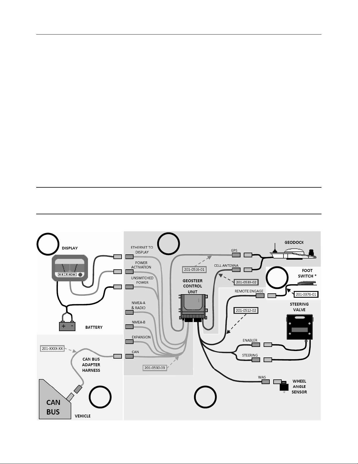
Each of the sub-categories is graphically shown in Figure 1-1 and is identified by a separately shaded area and the number
from the list above. Most installations will be slightly different from the example shown and may required different
components. These differences will be described in the vehicle specific information provided.
Note: Vehicle installation kits will generally include parts from only either sub-category 3a or 3b. Figure 1-1 shows examples
of how both 3a and 3b components would be connected to the GeoSteer system for demonstration purposes. Most installations
would not require both.
Figure 1-1 GeoSteer Installation Overview
1
2
4
3b
2 GeoSteer System
3a
Page 13

GeoSteer System Installation Overview
There are a number of options available for each sub-category. Each of these options comes with their own installation and
operational manuals that should be referred to during their part of the installation. This installation manual will provide the
basic instructions for installing the components for sub-category 2 and 3. However in order to provide a more complete
overview of the installation this section will provide some information on the other sub-categories as well.
1 Display Kits
GeoSteer is designed to be compatible with multiple models of Displays. The Displays are ordered as a separate component
and include their own installation instructions. The Display installation instructions will show how the Display and Display
Harnesses are installed on a vehicle and how they are connected to the GeoSteer Harnesses. There are three connections
between the Display and the GeoSteer Main Cable Harness that need to be connected:
•
ETHERNET TO DISPLAY – This connection is a RJ-45 connector that is plugged into the Ethernet port on the Display
or Display Harness to provide communications between the Display and the GeoSteer Control Unit.
•
POWER ACTIVATION – This connection is connected to the Display or Display Harness that provides a signal that
commands the GeoSteer to power up. When this signal is turned off, the GeoSteer will power down.
•
UNSWITCHED POWER – This is connected to a power source that provides 12 volts of unswitched DC power to the
GeoSteer. The power source should not be connected to a power supply that is connected to the vehicle’s ignition. This
source should be shown in the Display installation manual.
The Display installation kit will provide the necessary harnesses and instructions to provide power to the GeoSteer system and
to allow communications between the two. Use those instructions to complete the Display installation and to connect the
Display to the GeoSteer system after the Display mount has been installed.
2 GeoSteer System Kits
The GeoSteer Common kits represent the parts that are common on all installations. All GeoSteer Common kits include a
version of the GeoSteer Control Unit, the GeoSteer Main Harness, Operator’s Manual, a version of the GeoDock, GPS coax
cable, and when required, the Cell Modem coax cable. There are four base versions of this kit that are sold in different parts of
the world. They are:
•
GeoSteer CDMA – North America
•
GeoSteer No Modem – South America and Australia
•
GeoSteer GSM Europe – Europe
•
GeoSteer GSM Australia – Australia
Note: Geographic locations described above can change as market conditions change and are provided only to differentiate the
various options.
As part of the GeoSteer system kit, a GeoDock must also be selected. If the system has a cell modem a GeoDock with a cell
antenna is shipped otherwise the one without a cell antenna is shipped.
Note: Refer to your GeoSteer Operator’s Manual for the specific part numbers of kit components, descriptions, and capabilities
of all the parts that are supplied with each kit.
3 Vehicle Installation Kits
The GeoSteer system is designed to be compatible with many makes and models of vehicles available in today’s agricultural
market. GeoSteer is brand neutral and can be installed on any manufacturer’s vehicle including AGCO, Ag Chem, CaseIH,
Challenger, Fendt, John Deere, New Holland, Massey Ferguson, and many others. The GeoSteer system is also capable of
being installed on a variety of platforms including articulated tractors, combines, MFWD and standard front axle tractors,
floaters, sprayers, swathers, track tractors, and others. The same user interface can be used on all vehicles, regardless of the
Hardware Installation Guide 3
Page 14

GeoSteer System Installation Overview
make or model, making it easy for drivers to become familiar with the controls if the system is installed on multiple vehicle
types and makes.
To make installations simple and reliable, many vehicle-specific installation kits have been designed to fit each individual
make and model. These kits are available for vehicles that come from the factory with a factory installed steering system (ex.
Steer Ready, CAN Bus, or ISO Ready) as well as options for those vehicles that need a complete steering kit installed. Even if
there is not a vehicle-specific kit available for the vehicle, properly trained installers can often use a custom installation kit to
connect the GeoSteer system to the vehicle. Specific instructions for the vehicle installation kits are provided with the
installation kits. Refer to those instructions when installing the vehicle kit.
Note: The list of supported vehicle-specific kits is always being expanded. Contact your GeoSteer dealer for the latest list of
vehicle-specific installation kits to see if the vehicle being installed on has a released kit.
4 Accessory Kits
The GeoSteer system is compatible with optional accessory kits that can be ordered and installed to provide additional features
and capabilities. The primarily reason to install an accessory kit is to provide a radio modem link with a Base Station or an
OmniSTAR demodulator for OmniSTAR corrections. These accessories are not required for all installations and some are not
available in all locations. Order only the kits that are required to provide the accuracy level and communication needs required
for the installation. The accessory kits available at the time of this writing are:
•
GS-900 – 900 MHz radio modem for North America and Australia
•
GS-OmniSTAR – OmniSTAR demodulator for world
•
GS-410 – 410-430 MHz radio modem for world
•
GS-430 – 430-450 MHz radio modem for world
•
GS-450 – 450-470 MHz radio modem for world
•
Remote Engage Foot Switch – Remote Engage foot switch that can be attached to the GeoSteer Main Harness to allow the
user to start and stop AutoSteer with a foot switch
Note: Refer to your GeoSteer Operator’s Manual for specific part numbers of kit components, descriptions, and capabilities of
all the parts that are supplied with each kit.
Note: The list of accessory kits is always being expanded. Contact your GeoSteer dealer for the latest list of accessory kits.
Specific installation instructions for each accessory kit are provided with the kits themselves. Refer to those instructions when
installing the accessory kits
4 GeoSteer System
Page 15

Installation Procedure Outline
Installation Procedure Outline
This section provides an outline of all the steps that may need to be followed for a GeoSteer system installation. Not all steps
are required for every installation. For more detailed instructions of each step, follow the procedures provided in the
subsequent chapters of this installation manual.
1. Kit Verification – Verify that the installation kit ordered matches the vehicle that it is being installed on and that all the
parts have been shipped.
2. Steering Valve – If the vehicle requires a Hydraulic Steering Valve to be installed:
a. Configure the Hydraulic Steering Valve for the installation type.
b. Install the Hydraulic Steering Valve assembly.
c. Connect the Hydraulic Steering Valve to the vehicle hydraulic system with the hose kit.
3. Assisted Steering Unit – If the vehicle requires an Assisted Steering Unit such as OnTrac2+:
a. Install the Assisted Steering Unit on the steering wheel.
b. Install the Anti-Rotation Bracket.
4. Wheel Angle Sensor – If the vehicle requires a Wheel Angle Sensor to be installed:
a. Install the Wheel Angle Sensor Brackets
b. Install the Wheel Angle Sensor.
5. GeoDock – Install the GeoDock Mounting Bracket and GeoDock on top of the cab roof.
6. Display RAM Mount – Install the Display RAM Mount inside the cab.
7. Display – Install the Display specific components:
Note: GeoSteer can be matched with multiple Display options. Follow the instructions that come with your Display for the
procedures to install the Display and to connect the Display Harnesses to the Display and vehicle for power.
a. Install the Display using the RAM Mount.
b. Install the Display Harness.
c. Install the Power Harness for the Display.
8. GeoSteer Control Unit – Install the GeoSteer Control Unit at a solid point inside the cab of the vehicle.
Note: The GeoSteer Control Unit must be mounted in a place that is solid to the frame or cab of the vehicle. It must not
move independently of the vehicle (cannot be sitting on the floor of the cab loose). The mounting point must be vibration
free. Use the bracket(s) provided with the installation kit to mount the GeoSteer Control Unit when provided.
9. GeoSteer Harness – Install the GeoSteer Communication Harnesses. Route the harness connections between the
GeoSteer Control Unit’s left connector and:
a. The Display and/or Display Harnesses (see Display Manual for instructions)
b. The Power Activation connection (see Display Manual for instructions)
c. Power Supply (see Display Manual for instructions)
d. If the installation requires, the vehicle CAN connector(s)
Hardware Installation Guide 5
Page 16

Installation Procedure Outline
10. GeoSteer Vehicle-Specific Harness – If the installation requires, install the GeoSteer Vehicle Harnesses. Route the
harness connections between the GeoSteer Control Unit’s right connector to all the sensors and control points on the
vehicle. If this connector is not required for the installation, verify that the dummy plug has been attached to this port to
protect the electronics. The sensors and control points on the vehicle could include any of the following:
a. Wheel Angle Sensor
b. Steering Encoder
c. Pressure Transducer
d. Flow Sensor
e. Enabler Valves
f. Steering Valve
g. Assisted Steering Unit (ex OnTrac2+)
h. Any other vehicle-specific sensor connectors
11. GeoDock Cables – Install the GeoDock to GeoSteer Control Unit cables. Verify if the following cables have been run and
connected depending on the options installed on the system (not all are required for all installations):
a. GPS Coax Cable
b. Cell Modem Coax Cable
c. Radio Modem Data/Power Harnesses
12. Final Hardware Verification – Verify that all the bolts have been tightened, electrical and hydraulic connections are
securely connected, and that all hoses and cables have been routed safely and secured to the frame of the vehicle away
from moving parts with cable ties.
13. Final Hydraulic Install Verifications – If the vehicle requires a Hydraulic Steering Valve:
a. Clear all bystanders and start the vehicle and check for any oil leaks.
b. Adjust the Load Sense Pressure Relief Valve on the Steering Valve if the Steer Valve requires this adjustment.
14. Final Vehicle Set Up – Once the system has been fully installed, set the vehicle up in the GeoSteer system
a. Power ON the GeoSteer system.
b. Create a new vehicle profile.
c. Calibrate the vehicle.
d. If necessary, tune the vehicle to improve performance.
e. Verify the system has been installed properly and operates satisfactorily.
15. Vehicle Checklist – Fill out the Installation Checklist at the end of this Installation Manual.
6 GeoSteer System
Page 17
2
Steering Valve Installation
The Steering Valve Installation chapter information is provided in the following sections:
•
Overview
•
Steering Valve Installation
Overview
If the vehicle does not come with a factory installed steering system with a factory installed Steering Valve, the vehicle will
need to have a Steering Valve installed. If the vehicle is “Steer Ready” from the factory, this section can be skipped during the
installation. Contact the vehicle’s service provider to verify if the vehicle is “Steer Ready” prior to beginning the installation.
Note: Refer to this section only if this installation requires the installation of a Steering Valve.
High-Pressure Fluid Hazard
If the installation requires working on the hydraulic system
on the vehicle, read and understand the hydraulic sections
of the vehicle manufacturer’s operators manual before
starting the installation. Wear hand and eye protection while
performing hydraulic system maintenance. Relieve hydraulic
system pressure before servicing the hydraulic system.
Figure 2-1 Typical AutoSteer Steering Valve
Hardware Installation Guide 7
Page 18
Steering Valve Installation
Steering Valve Installation
The installation of a Steering Valve requires a trained AutoSteer installation specialist that is familiar with hydraulics. Failure
to properly connect the Steering Valve and adjust the Load Sense Pressure Relief Valve can cause costly damage to the
vehicle’s hydraulic system. For many vehicle makes and models, specific hydraulic installation kits are available to make this
process easier and safer. These kits come with the required, Steering Valve, hoses, hose adapters, and instructions on how to
properly connect the system.
The GeoSteer system does support “Custom” installations on vehicles that are not currently supported with vehicle-specific
kits. This requires that the installer be trained in the hydraulics systems of the vehicle as well as trained with the advanced
configurations of the Steering Valve.
Note: If the installer is not familiar with the following terms and hydraulic options, they SHOULD NOT attempt a custom
installation or damage to the vehicle could occur.
•
Power Beyond – Does the vehicle have one and is this a viable way to connect to the Steering Valve?
•
Steering Orbitrol – Where is this located, is this a viable way to connect to the Steering Valve, and what type of hydraulic
system does the Orbitrol use?
•
Open Center
•
Closed Center
•
Pressure Compensated
•
Circuit Relief Valve – How is the vehicle’s hydraulic system protected from over pressurization?
•
Load Sense – Does the system use a Load Sense circuit? What type of Load Sense is installed?
•
Standard
•
Dynamic
•
Reactive Steering – Does the vehicle have Reactive Steering?
•
Steering Valve Configuration – How should the Steering Valve be configured for each of the possible installation
scenarios?
Note: Installing the Steering Valve incorrectly can cause damage to the vehicle and/or Steering Valve. Only trained hydraulic
specialists should attempt to install a Steering Valve kit on a vehicle. If any of the terms and questions listed above are not
understood, an installation, especially a “Custom” installation, should not be attempted.
Refer to the Steering Valve Installation chapter in the vehicle-specific AutoSteer Installation
Manual provided with the installation kit for the instructions for preparing the Steering Valve,
installing the Steering Valve, and connecting the hoses between the vehicle and the Steering
Valve.
After the installation is complete, refer to the Post-Installation Procedures and Information
chapter for additional information on checking for hydraulic leaks and, if necessary, setting the
Load Sense Pressure Relief Valve.
Note: If the Steering Valve has a Load Sense Pressure Relief Valve, it is important to set this properly after the complete
installation of the system or system damage or poor performance may occur.
8 GeoSteer System
Page 19

3
Assisted Steering Unit Installation
The Assisted Steering Unit Installation chapter information is provided in the following section:
•
Overview
•
Assisted Steering Unit Installation
Overview
Some installations require the installation of an Assisted Steering Unit (ex. OnTrac2, OnTrac2+, etc.) This unit takes the place
of the Steering Valve or the factory installed system. The Assisted Steering Unit is mounted directly on the Steering Wheel and
controls the steering of the vehicle by mechanically turning the Steering Wheel on the vehicle itself.
Note: Refer to this section only if this installation requires the installation of an Assisted Steering Unit.
Figure 3-1 Typical Assisted Steering Unit
Assisted Steering Unit Installation
If an Assisted Steering Unit is being installed, refer to the Installation Manual that comes with
the Assisted Steering Unit itself for detailed instructions on installing the Mechanical Drive Unit
(MDU) and the anti-rotation brackets that come with the Assisted Steering Unit kit.
If a vehicle-specific anti-rotation kit is to be installed instead of the generic anti-rotation
brackets, refer to the instructions showing how to attach the Mechanical Drive Unit to the antirotation kit that come with the vehicle-specific anti-rotation kit.
Hardware Installation Guide 9
Page 20

Assisted Steering Unit Installation
Note: The GeoSteer Control Unit will take the place of the ECU2 or ECU4 described in the Assisted Steering Unit installation
manual so disregard those instructions in the Assisted Steering Unit Installation Manual for installing the ECU2 or ECU4. For
GeoSteer installations, the orientation of the GeoSteer Control Unit does not matter. Refer to the mounting instructions of the
GeoSteer Control Unit later in this manual.
10 GeoSteer System
Page 21

4
Wheel Angle Sensor (WAS) Installation
The Wheel Angle Sensor (WAS) Installation chapter information is provided in the following section:
•
Overview
•
Wheel Angle Sensor Installation
Overview
If the vehicle does not come with a factory installed steering system with a factory installed Wheel Angle Sensor, the vehicle
will need to have a Wheel Angle Sensor installed. In most situations, if the vehicle is “Steer Ready” from the factory, this
section can be skipped during the installation; however some factory supplied Wheel Angle Sensors are not compatible with
the GeoSteer system. Contact the vehicle’s service provider to verify if the vehicle is “Steer Ready” prior to beginning the
installation. If the factory installed Wheel Angle Sensor is not compatible, a Wheel Angle Sensor will be part of the installation
kit.
Note: Refer to this section only if this installation requires the installation of a Wheel Angle Sensor.
If the vehicle has a Wheel Angle Senor as part of the
installation, always shut off the vehicle when working
around the steering axle while installing, checking, and
adjusting the Wheel Angle Sensor and rod lengths. The
steering axle could move suddenly and cause severe injury
or death.
Figure 4-1 Typical Wheel Angle Sensor Assembly
Hardware Installation Guide 11
Page 22

Wheel Angle Sensor Installation
Wheel Angle Sensor Installation
A Wheel Angle Sensor is required to provide the GeoSteer system with an indicator of what direction the steering axle is
pointing compared to the vehicle position at all times. This allows the system to more accurately determine how far and how
fast it must command the steering axle to reach the required position for smooth steering. It is critical that the Wheel Angle
Sensor be installed correctly with adequate counts to provide a high resolution of the steering axle’s position.
The Wheel Angle Sensor kit comes with rods that need to be cut to the correct length prior to installing them. The vehiclespecific installation manual provides guidelines for the lengths these rods need to be cut for a typical installation; however
these values are for reference only. There are many different axle configurations and wheel stop settings that an individual
vehicle can be set that cannot be addressed in a manual. Though the manual provides cut lengths and suggested rod assembly
lengths, it is ultimately the installer’s responsibility to verify the suggested measurements will work on their particular
installation. If necessary, the lengths may need to be modified to prevent damage to the vehicle and/or Wheel Angle Sensor.
Note: Prior to turning the wheels manually or with the GeoSteer system, always verify that the Wheel Angle Sensor linkage
rods will not bind, be damaged, or damage the vehicle or Wheel Angle Sensor when the steering axle is turned from the full
left to full right positions. Always disconnect the linkage rods the first time the wheel is turned to the maximum limit.
Reconnect the linkage rods at the maximum limit and then disconnect them while they are moved to the opposite limit.
Refer to the Wheel Angle Sensor (WAS) Installation chapter in the vehicle-specific AutoSteer
Installation Manual provided with the installation kit for the instructions for installing the
Wheel Angle Sensor Mounting Brackets, installing the Wheel Angle Sensor, cutting the linkage
rods, connecting the linkage rods, and verifying the Wheel Angle Sensor is installed properly.
12 GeoSteer System
Page 23

GeoDock Installation
The GeoDock Installation chapter contains information in the following sections:
•
Safety Notes
•
Overview
•
GeoDock Pro
•
GeoDock Pro – No Cell
•
GeoDock Installation
Safety Notes
5
•
The GeoSteer system must be powered OFF when installing or removing the GeoDock.
•
The GeoDock must always be firmly secured to the GeoDock Mounting Bracket whenever the vehicle is in operation to
prevent the GeoDock from falling off.
•
The GeoDock must be removed when transporting the vehicle at speeds above 30 mph (50 km/h).
•
Use a ladder to install the GeoDock if a stable platform on the vehicle is not available.
Verify that you are in a stable position on the vehicle’s
platform or stairs when installing or removing the GeoDock
so you do not fall. If the vehicle does not provide a safe
platform, use a ladder to safely access the vehicle’s roof.
Overview
The GeoDock is the removable assembly that includes the GPS antenna and, if the installation requires, cell modem antenna
that is mounted on the roof of the vehicle. The GeoDock assembly is also the location where the optional radio modem antenna
and radio modem or OmniSTAR demodulator accessory kits are installed. The GeoDock is attached magnetically to a
GeoDock Mounting Plate that is permanently attached to the roof of the vehicle. This allows the GeoDock to be quickly
removed and reattached in the same location on the vehicle.
As part of the of the GeoSteer system kit, the GeoDock is a configurable component. The GeoDock comes in two versions to
fit the needs of the user:
•
GeoDock Pro
•
GeoDock Pro – No Cell
Hardware Installation Guide 13
Page 24

Overview
GeoDock Pro
The GeoDock Pro has a built in penta-band cell modem antenna and is capable of receiving the L1 and L2 frequencies from
GPS, the G1 and G2 frequencies from Glonass, and the L-Band frequencies for OmniSTAR. This gives the GeoDock Pro the
ability to be very flexible and provide high accuracy GPS signals and corrections.
The GeoDock Pro also provides multiple options for correction sources to improve the accuracy of the GPS signal. It is
designed to house the various radio modems that may be necessary to receive a correction source from a base station.
Accessory kits that provide support for 900 MHz ISM band, 400-470 MHz narrowband UHF, or OmniSTAR are supported.
Figure 5-1a GeoDock Pro
GeoDock Pro – No Cell
The GeoDock Pro - No Cell is similar to the GeoDock Pro but does not include the built in cell modem antenna. It is used in
applications that do not require cell phone connectivity.
Figure 5-1b GeoDock Pro – No Cell
14 GeoSteer System
Page 25

GeoDock Installation
GeoDock Installation
1. Remove the GeoDock Mounting Plate from the installation kit. The plate will have four pieces of high bond tape on the
bottom of it that will be used to hold the plate to the top of the vehicle roof.
Note: Notice the three tabs that are used to center the GeoDock when attached to the plate. The two tabs should always be
on the left side of the machine.
Figure 5-2 GeoDock Mounting Plate
Self Centering Tabs
2. Locate a flat area at least 10 inches by 20 inches (25 cm by 50 cm) along the center line of the cab roof.
Note: If a solid flat location cannot be found, it may be necessary to build a mounting bracket to allow the GeoDock
Mounting Plate to be mounted firmly. The plate has mounting holes for securing to the vehicle or a bracket when required.
Figure 5-3 Locate Flat Area on Cab Roof
Flat Area along Centerline of Vehicle
Rear of Cab
3. Thoroughly clean the area on the roof with soap and water to remove ALL dirt.
Note: Cabs with a great deal of oxidation or texture may require more abrasive cleaning methods to achieve a clean
surface. When necessary, use a scour pad such as Scotch-Brite to thoroughly clean the surface until it is smooth and free
of contaminants.
Hardware Installation Guide 15
Page 26

GeoDock Installation
4. Use alcohol wipes to finish cleaning the area to verify that all oil and grease is removed. Let the area dry.
Note: It is very important that all dirt and oil have been removed from the mounting point on the cab so that the high bond
strips will hold the GeoDock Mounting Plate to the roof.
5. Use fixed points on the roof and a tape measure to find the exact centerline of the vehicle and mark that position on the
area that has been cleaned with a marking device.
Note: On some vehicles the center of the cab may not be the center of the vehicle as the cab could be offset. Always verify
that the centerline marked is the centerline of the vehicle if the cab is not centered over the vehicle.
Figure 5-4 Mark Centerline
Mark the Centerline of the Vehicle
6. Remove the four adhesive backings on the GeoDock Mounting Plate.
Figure 5-5 Remove Adhesive Backing from GeoDock Mounting Plate
Rear of Cab
Remove Backing
16 GeoSteer System
Page 27

GeoDock Installation
7. Use the two notches on the GeoDock Mounting Plate to center it over the marks that show the centerline of the vehicle.
Carefully place the GeoDock Mounting Plate on the clean area.
Note: The GeoDock Mounting Plate is orientation dependent. Verify that the two taps are on the left side of the vehicle
and the single tab is on the right side. The front of the GeoDock Mounting Plate is marked FRONT and should be facing
the front of the vehicle.
Note: Verify that the GeoDock Mounting Plate is square with the vehicle prior to letting the adhesive stick to the roof.
o
Note: The ideal temperature for applying the mounting plate using high bond tape is 70
F to 100oF (21oC to 38oC). Do not
apply the high bond tape at temperatures below 60oF (15oC).
Figure 5-6 GeoDock Mounting Plate Attached to Roof
FRONT Mark towards Front of Vehicle
GeoDock Mounting Plate
Rear of Cab
Hardware Installation Guide 17
Page 28

GeoDock Installation
8. Once the GeoDock Mounting Plate is in the proper location, firmly press the adhesive areas to ensure a good contact is
made with the roof. Apply pressure for a few seconds to all four corners of the plate.
Note: The high bond tape uses a permanent adhesive. Verify and confirm the correct position and orientation of the
mounting plate before applying to the vehicle roof.
9. If any of the accessory kits for the GeoDock have been ordered, follow the instructions that come with the accessory kits
and install those components.
10. Place the GeoDock on the GeoDock Mounting Plate.
Note: Make sure the tabs line up between the GeoDock and the GeoDock Mounting Plate.
Figure 5-7 GeoDock Installed
18 GeoSteer System
Page 29

GeoDock Installation
11. To remove the GeoDock from the GeoDock Mounting Plate, pry the GeoDock loose from either the front or rear of the
GeoDock by the metal bracket beneath the plastic housing.
Note: Never remove the GeoDock by pulling up on the plastic housing or by the coax cables. This could cause damage to
the unit.
Figure 5-8 Removing GeoDock from GeoDock Mounting Bracket
Pry Up from these Points Only
Hardware Installation Guide 19
Page 30

Page 31

6
Display Installation
The Display Installation chapter contains information in the following sections:
•
Overview
•
Display Installation
Overview
A RAM mount ball is provided with the installation kit. Mount the RAM ball in the cab so that the Display can be attached
later. The GeoSteer system is compatible with a number of different Displays, refer to your Display’s User Manual for
instructions on installing the Display.
Many custom Display mounting brackets are available through your AutoSteer dealer to mount the RAM ball base to vehiclespecific models without drilling holes. Contact your AutoSteer dealer for details.
Display Installation
The installation kit provides a U-bolt RAM mount ball that can be attached to a round bar or a Flat Plate RAM mount ball that
can be bolted to a flat surface. Locate a position in the cab that will allow the RAM mount ball to be attached. The location
should allow the Display to be positioned close enough for the driver to press the AutoSteer Engage button on the screen
comfortably (the lower, right hand corner). It should also be positioned so that the Display does not block the operator’s field
of view.
Figure 6-1 U-Bolt RAM Mount Ball
Hardware Installation Guide 21
Page 32

Display Installation
Figure 6-2 Flat Plate RAM mount ball
Once the RAM mount has been installed, follow the instructions in the Display’s User Manual to install the Display in the
vehicle.
22 GeoSteer System
Page 33

7
GeoSteer Control Unit Installation
The GeoSteer Control Unit Installation chapter contains information in the following sections:
•
Overview
•
GeoSteer Control Unit Installation
Overview
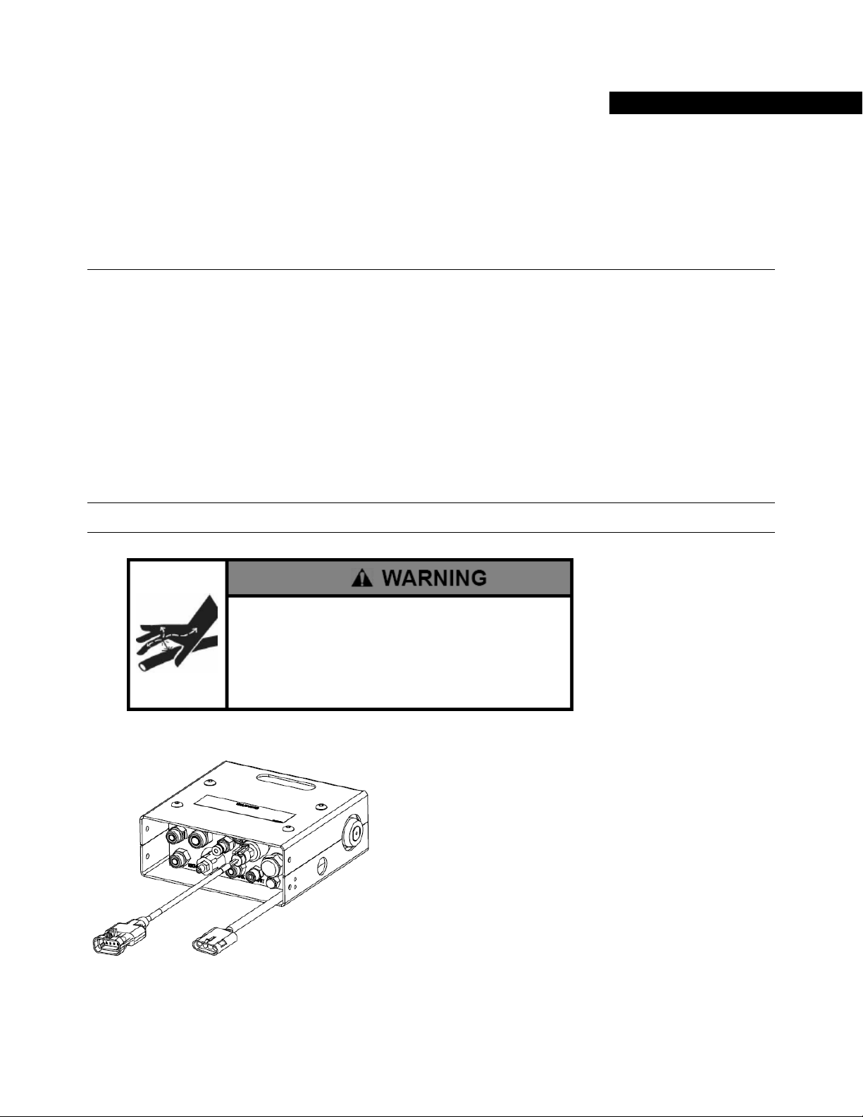
The GeoSteer Control Unit is the central hub of the system. The GeoSteer Control Unit contains the GPS receiver, the cell
modem, the Electrical Control Unit that interfaces with the vehicle, and the software for the user interface. The GeoSteer
Control Unit also contains the sensors that detect movement of the vehicle. All connections are routed to this unit via two 30
pin connectors.
Figure 7-1 GeoSteer Control Unit
GeoSteer Control Unit Cable
Connections
To avoid possible damage to electronic circuits caused by
electrostatic discharge, do not touch the contacts on the
GeoSteer Control Unit electrical connectors at any time.
Hardware Installation Guide 23
Page 34

GeoSteer Control Unit Installation
GeoSteer Control Unit Installation
It is important that the GeoSteer Control Unit is mounted on a solid mounting bracket attached to a solid point on the vehicle.
The bracket must be sturdy enough to prevent any vibrations or move independently of the vehicle frame. The GeoSteer
Control Unit contains sensors that detect movement of the vehicle and any movement that is not directly related to the
vehicle’s frame may negatively affect control performance.
The GeoSteer Control Unit is weatherproof and can be mounted inside or outside the cab. However it is recommended in most
situations to mount the GeoSteer Control Unit inside the cab if possible. This is dependent on whether a solid location can be
located. The GeoSteer Control Unit can be mounted at any angle; however to simplify the vehicle setup steps in the AutoSteer
system later, it is recommended to install the GeoSteer Control Unit at right angles to the vehicle’s direction of motion. The
connectors should never point upwards.
The vehicle-specific installation kits provide the bracket, any additionally required hardware, and the instructions specific to
the vehicle that it is being installed on. The vehicle setup in the AutoSteer software also has the default angles for the GCU
loaded so odd angles can be used more easily. Refer to the ECU Bracket Installation Manual that comes with the installation
kit for instructions for installing the GeoSteer Control Unit.
Note: If the installation is a custom installation, it is important to mount the GeoSteer Control Unit at a solid point on the
vehicle. Failure to mount the GeoSteer Control Unit properly may cause the system to perform at a lower than optimum level.
Verify that the bracket is sturdy and that it can provide this solid mounting point.
Attach the GeoSteer Control Unit to the mounting bracket with four 8-32 x 1/2 Hex Screws or four 8-32 x 3/4" Hex Screws
(depending on the ECU Mounting Bracket) using a 1/4" nut driver. Do not over tighten.
Figure 7-2 Example of GeoSteer Control Unit Installed
Refer to the GeoSteer Operator’s Manual for LED definitions and troubleshooting information based on the LED information.
24 GeoSteer System
Page 35

Connecting System Cables
The Connecting System Cables chapter provides information in the following sections:
•
Overview
•
Cable Diagram Examples
•
AutoSteer Valve Installation Example
•
Assisted Steering Unit Installation Example
•
John Deere AutoTrac Ready Installation Example
•
Case AccuGuide / New Holland IntelliSteer Ready Articulated Installation Example
•
Case AccuGuide / New Holland IntelliSteer Ready MFWD Installation Example
•
MacDon Valve Installation Example
•
CAN Bus Installation Example
•
Dual CAN Bus Installation Example
•
CAT Valve Installation Example
•
Deere Track Installation Example
•
Prepare the Cab Cable Access Point
•
Attach Harnesses to GeoSteer Control Unit
•
Vehicle-Specific Harness
•
GeoSteer Main Cable Harness
•
Coax Cables
•
Power Supply Requirements
•
Warning Label
8
Overview
The final step of the installation is to connect all the components installed with the various harnesses that come with the
system. Each vehicle is different in how the cables are routed and what components are connected. The Cable Diagram
Examples in this chapter of this manual provides some generic cable diagrams of how the GeoSteer system can be connected
on a number of different vehicle types. The Cable Diagram section in the AutoSteer Installation Manual that come with the
vehicle-specific installation kits also provide some additional detail to the vehicle-specific components that are connected.
Refer to the Display’s User Manual for additional instructions on how to connect the GeoSteer system to the Display.
Note: When routing harnesses, verify that all harnesses are routed away from moving parts and sharp objects. Secure the
harnesses with cable ties to ensure they are not damaged.
Hardware Installation Guide 25
Page 36

Cable Diagram Examples
Cable Diagram Examples
The GeoSteer system is connected to the various components on the vehicle differently
depending on the vehicle it is installed on. The following diagrams are provided as examples of
the basic connections for four standard installations. Refer to the Cable Diagram section of the
Installation Overview chapter in the vehicle-specific AutoSteer Installation Manual provided
with the installation kit for more detailed instructions of the vehicle-specific connections and
adapter used.
26 GeoSteer System
Page 37

Cable Diagram Examples
AutoSteer Valve Installation Example
•
Cell Antenna Coax Cable (PN 201-0539-02) is not required if not using a Cell Modem.
•
Foot Switch (PN 201-0376-01) is an optional accessory component.
•
GeoSteer can be connected to multiple models of Displays. Refer to the Display User Manual for more detailed instructions
on how to connect the GeoSteer to the Display data and power ports.
•
Component definitions
•
DISPLAY – The Display that is connected to the GeoSteer system
•
BATTERY – The battery terminals for the power source for the GeoSteer system and Display
•
GEOSTEER CONTROL UNIT – The GeoSteer Control Unit
•
GEODOCK – The GeoDock unit mounted on the roof
•
FOOT SWITCH* – The optional Foot Switch that can be used for Remote Engage (not necessary for installation)
•
STEERING VALVE – The Steering Valve used to steer the vehicle
•
WHEEL ANGLE SENSOR – The device used to measure the angle of the wheel position
Figure 8-1 AutoSteer Valve Installation Example
Hardware Installation Guide 27
Page 38

Cable Diagram Examples
Assisted Steering Unit Installation Example
•
Cell Antenna Coax Cable (PN 201-0539-02) is not required if not using a Cell Modem.
•
Foot Switch (PN 201-0376-01) is an optional accessory component.
•
GeoSteer can be connected to multiple models of Displays. Refer to the Display User Manual for more detailed instructions
on how to connect the GeoSteer to the Display data and power ports.
•
Component definitions
•
DISPLAY – The Display that is connected to the GeoSteer system
•
BATTERY – The battery terminals for the power source for the GeoSteer system and Display
•
GEOSTEER CONTROL UNIT – The GeoSteer Control Unit
•
GEODOCK – The GeoDock unit mounted on the roof
•
FOOT SWITCH* – The optional Foot Switch that can be used for Remote Engage (not necessary for installation)
•
ASSISTED STEERING UNIT – The Assisted Steering Unit mounted to the steering wheel of the vehicle
Figure 8-2 Assisted Steering Unit Installation Example
28 GeoSteer System
Page 39

Cable Diagram Examples
John Deere AutoTrac Ready Installation Example
•
Cell Antenna Coax Cable (PN 201-0539-02) is not required if not using a Cell Modem.
•
Foot Switch (PN 201-0376-01) is an optional accessory component.
•
GeoSteer can be connected to multiple models of Displays. Refer to the Display User Manual for more detailed instructions
on how to connect the GeoSteer to the Display data and power ports.
•
TERMINATORS are connected to the end of the vehicle’s AutoTrac Ready Harness at the two Steering Wheel Encoder
connectors and at the Wheel Angle Sensor connector. These parts are different depending on the model of the vehicle..
•
DUMMY CONNECTORS are connected to the AutoTrac Steering Valve connector of the vehicle’s AutoTrac Ready
Harness and to the cable coming from the Steering Wheel Encoder that is not connected to the GeoSteer Harness.
•
Wheel Angle Sensor ADAPTER Harness is installed to connect to the factory installed Wheel Angle Sensor to the
GeoSteer Harness. This adapter is different depending on the model of the vehicle..
•
Component definitions
•
DISPLAY – The Display that is connected to the GeoSteer system
•
BATTERY – The battery terminals for the power source for the GeoSteer system and Display
•
GEOSTEER CONTROL UNIT – The GeoSteer Control Unit
•
GEODOCK – The GeoDock unit mounted on the roof
•
FOOT SWITCH* – The optional Foot Switch that can be used for Remote Engage (not necessary for installation)
•
STEERING WHEEL – This is the steering wheel which has an encoder attached to it for kick out
•
AUTOTRAC STEERING VALVE – The factory supplied Steering Valve used to steer the vehicle
•
WHEEL ANGLE SENSOR – The factory supplied Wheel Angle Sensor used to measure the angle of the wheel
position
•
AUTOTRAC HARNESS – The existing factory supplied harness connecting the components
Figure 8-3 John Deere AutoTrac Ready Installation Example
Hardware Installation Guide 29
Page 40

Cable Diagram Examples
Case AccuGuide / New Holland IntelliSteer Ready Articulated
Installation Example
•
Cell Antenna Coax Cable (PN 201-0539-02) is not required if not using a Cell Modem.
•
Foot Switch (PN 201-0376-01) is an optional accessory component.
•
GeoSteer can be connected to multiple models of Displays. Refer to the Display User Manual for more detailed instructions
on how to connect the GeoSteer to the Display data and power ports.
•
Component definitions
•
DISPLAY – The Display that is connected to the GeoSteer system
•
BATTERY – The battery terminals for the power source for the GeoSteer system and Display
•
GEOSTEER CONTROL UNIT – The GeoSteer Control Unit
•
GEODOCK – The GeoDock unit mounted on the roof
•
FOOT SWITCH* – The optional Foot Switch that can be used for Remote Engage (not necessary for installation)
•
ACCUGUIDE / INTELLISTEER HARNESS – The 40 pin connector on the factory supplied AccuGuide / IntelliSteer
Harness
•
WHEEL ANGLE SENSOR – The Wheel Angle Sensor used to measure the angle of the wheel position
Figure 8-4 Case AccuGuide / New Holland IntelliSteer Ready Articulated Installation Example
30 GeoSteer System
Page 41

Cable Diagram Examples
Case AccuGuide / New Holland IntelliSteer Ready MFWD
Installation Example
•
Cell Antenna Coax Cable (PN 201-0539-02) is not required if not using a Cell Modem.
•
Foot Switch (PN 201-0376-01) is an optional accessory component.
•
GeoSteer can be connected to multiple models of Displays. Refer to the Display User Manual for more detailed instructions
on how to connect the GeoSteer to the Display data and power ports.
•
Component definitions
•
DISPLAY – The Display that is connected to the GeoSteer system
•
BATTERY – The battery terminals for the power source for the GeoSteer system and Display
•
GEOSTEER CONTROL UNIT – The GeoSteer Control Unit
•
GEODOCK – The GeoDock unit mounted on the roof
•
FOOT SWITCH* – The optional Foot Switch that can be used for Remote Engage (not necessary for installation)
•
ACCUGUIDE / INTELLISTEER HARNESS – The 40 pin connector on the factory supplied AccuGuide / IntelliSteer
Harness
•
ACCUGUIDE STEERING VALVE – The Enabler connector on the factory supplied Steering Valve
Figure 8-5 Case AccuGuide / New Holland IntelliSteer Ready MFWD Installation Example
Hardware Installation Guide 31
Page 42

Cable Diagram Examples
MacDon Valve Installation Example
•
Cell Antenna Coax Cable (PN 201-0539-02) is not required if not using a Cell Modem.
•
Foot Switch (PN 201-0376-01) is an optional accessory component.
•
GeoSteer can be connected to multiple models of Displays. Refer to the Display User Manual for more detailed instructions
on how to connect the GeoSteer to the Display data and power ports.
•
Component definitions
•
DISPLAY – The Display that is connected to the GeoSteer system
•
BATTERY – The battery terminals for the power source for the GeoSteer system and Display
•
GEOSTEER CONTROL UNIT – The GeoSteer Control Unit
•
GEODOCK – The GeoDock unit mounted on the roof
•
FOOT SWITCH* – The optional Foot Switch that can be used for Remote Engage (not necessary for installation)
•
STEERING VALVE – The MacDon Steering Valve used to steer the vehicle
•
PINTLE ARM SENSOR – The device used to measure the angle of the pintle arm position
Figure 8-6 MacDon Valve Installation Example
32 GeoSteer System
Page 43

Cable Diagram Examples
CAN Bus Installation Example
•
Cell Antenna Coax Cable (PN 201-0539-02) is not required if not using a Cell Modem.
•
Foot Switch (PN 201-0376-01) is an optional accessory component.
•
Remote Engage Harness (PN 201-0563-01) is an optional accessory component required to allow a CAN Bus vehicle to
use the optional Foot Switch.
•
If the Remote Engage Harness is not installed, the Dummy Plug (201-0566-01) must be installed on the Vehicle port of the
GeoSteer Control Unit to protect the connectors.
•
GeoSteer can be connected to multiple models of Displays. Refer to the Display User Manual for more detailed instructions
on how to connect the GeoSteer to the Display data and power ports.
•
Component definitions
•
DISPLAY – The Display that is connected to the GeoSteer system
•
BATTERY – The battery terminals for the power source for the GeoSteer system and Display
•
GEOSTEER CONTROL UNIT – The GeoSteer Control Unit
•
GEODOCK – The GeoDock unit mounted on the roof
•
FOOT SWITCH* – The optional Foot Switch that can be used for Remote Engage (not necessary for installation)
•
REMOTE ENGAGE HARNESS* - The optional harness to connect the GeoSteer Control Unit to Foot Switch
•
VEHICLE CAN BUS – The CAN Bus or ISO Bus connector or connectors that allow the GeoSteer to communicate
directly to the vehicle’s steering system
•
CAN BUS ADAPTER HARNESS – Harness connects the GeoSteer Main Harness to the vehicles CAN connector and
is a vehicle dependent
Figure 8-7 CAN Bus Installation Example
Hardware Installation Guide 33
Page 44

Cable Diagram Examples
Dual CAN Bus Installation Example
•
Cell Antenna Coax Cable (PN 201-0539-02) is not required if not using a Cell Modem.
•
Foot Switch (PN 201-0376-01) is an optional accessory component.
•
Remote Engage Harness (PN 201-0563-01) is an optional accessory component required to allow a CAN Bus vehicle to
use the optional Foot Switch.
•
If the Remote Engage Harness is not installed, the Dummy Plug (201-0566-01) must be installed on the Vehicle port of the
GeoSteer Control Unit to protect the connectors.
•
GeoSteer can be connected to multiple models of Displays. Refer to the Display User Manual for more detailed instructions
on how to connect the GeoSteer to the Display data and power ports.
•
To create a second CAN port (B) from the GeoSteer Main Harness, the Expansion Adapter Harness (PN 201-0556-01)
must be attached to the EXPANSION port of the GeoSteer Main Harness.
•
Component definitions
•
DISPLAY – The Display that is connected to the GeoSteer system
•
BATTERY – The battery terminals for the power source for the GeoSteer system and Display
•
GEOSTEER CONTROL UNIT – The GeoSteer Control Unit
•
GEODOCK – The GeoDock unit mounted on the roof
•
FOOT SWITCH* – The optional Foot Switch that can be used for Remote Engage (not necessary for installation)
•
REMOTE ENGAGE HARNESS* - The optional harness to connect the GeoSteer Control Unit to Foot Switch
•
VEHICLE CAN BUS – Depending on the vehicle this is the one or two CAN Bus or ISO Bus connector or connectors
that allow the GeoSteer to communicate directly to the vehicle’s steering system
•
CAN BUS ADAPTER HARNESS –Harness that connects the GeoSteer Main Harness to the vehicles CAN connector
and is a vehicle dependent, Port A of the CAN Bus Adapter Harness connects directly to the GeoSteer Main Harness,
Port B of the CAN Bus Adapter Harness connects to the Expansion Adapter Harness
Figure 8-8 Dual CAN Bus Installation Example
34 GeoSteer System
Page 45

Cable Diagram Examples
CAT Valve Installation Example
•
Cell Antenna Coax Cable (PN 201-0539-02) is not required if not using a Cell Modem.
•
Foot Switch (PN 201-0376-01) is an optional accessory component.
•
Remote Engage Harness (PN 201-0563-01) is an optional accessory component required to allow CAT vehicle to use the
optional Foot Switch. The Remote Engage port from the SA Module Harness is not used.
•
If the Remote Engage Harness is not installed, the Dummy Plug (201-0566-01) must be installed on the Vehicle port of the
GeoSteer Control Unit to protect the connectors.
•
GeoSteer can be connected to multiple models of Displays. Refer to the Display User Manual for more detailed instructions
on how to connect the GeoSteer to the Display data and power ports.
•
Component definitions
•
DISPLAY – The Display that is connected to the GeoSteer system
•
BATTERY – The battery terminals for the power source for the GeoSteer system and Display
•
GEOSTEER CONTROL UNIT – The GeoSteer Control Unit
•
GEODOCK – The GeoDock unit mounted on the roof
•
FOOT SWITCH* – The optional Foot Switch that can be used for Remote Engage (not necessary for installation)
•
REMOTE ENGAGE HARNESS* - The optional harness to connect the GeoSteer Control Unit to Foot Switch
•
STEERING VALVE – The CAT Valve used to steer the vehicle
•
WHEELED SA MODULE – Allows GeoSteer Control Unit to command the CAT Steering Valve via CAT SA Module
Harness and Expansion Adapter Harness
Figure 8-9 CAT Valve Installation Example
Hardware Installation Guide 35
Page 46

Cable Diagram Examples
Deere Track Installation Example
•
Cell Antenna Coax Cable (PN 201-0539-02) is not required if not using a Cell Modem.
•
Foot Switch (PN 201-0376-01) is an optional accessory component.
•
Remote Engage Harness (PN 201-0563-01) is an optional accessory component required to allow John Deere Track vehicle
to use the optional Foot Switch. The Armrest Switch ARS port from the SA Module Harness is not used.
•
If the Remote Engage Harness is not installed, the Dummy Plug (201-0566-01) must be installed on the Vehicle port of the
GeoSteer Control Unit to protect the connectors.
•
GeoSteer can be connected to multiple models of Displays. Refer to the Display User Manual for more detailed instructions
on how to connect the GeoSteer to the Display data and power ports.
•
Component definitions
•
DISPLAY – The Display that is connected to the GeoSteer system
•
BATTERY – The battery terminals for the power source for the GeoSteer system and Display
•
GEOSTEER CONTROL UNIT – The GeoSteer Control Unit
•
GEODOCK – The GeoDock unit mounted on the roof
•
FOOT SWITCH* – The optional Foot Switch that can be used for Remote Engage (not necessary for installation)
•
REMOTE ENGAGE HARNESS* - The optional harness to connect the GeoSteer Control Unit to Foot Switch
•
JOHN DEERE SST OR SSU MODULE – This is the metal case of the John Deere Steering controller that must be
grounded to the SA Module Harness
•
DEERE TRACK SA MODULE – Allows GeoSteer Control Unit to command the John Deere Track via Deere Track
SA Module Harness and Expansion Adapter Harness
Figure 8-10 John Deere Track Installation Example
36 GeoSteer System
Page 47

Prepare the Cab Cable Access Point
Prepare the Cab Cable Access Point
In all installations cables will have to be routed into and out of the cab to the various sensors and components. Most vehicles
have a cab cable access point on the rear window, floor panel, or side bulkhead that allows this to happen easily with a
minimum amount of cab modifications. Always find the cab cable access point on the vehicle when starting to route harnesses
and prepare it so that the cables can be routed when needed.
Refer to the Connecting System Cables chapter in the vehicle-specific AutoSteer Installation
Manual provided with the installation kit to locate the cab cable access point for the vehicle the
system is being installed on.
Note: It is important to ensure the cables are protected where they are routed and that after the installation is complete, the
cable access point is resealed to ensure that outside air or moisture cannot get into the cab during normal machine operations.
Attach Harnesses to GeoSteer Control Unit
The GeoSteer Control Unit has two 30 port connectors. These connectors are keyed so that the correct harnesses or plug can be
attached in the proper port and orientation. The connectors on the GeoSteer Control Unit and the cables also have a colored dot
to aid attaching the cables properly. The GeoSteer Main Cable Harness is represented by a Yellow dot and the Vehicle Specific
Harnesses are represented by a White dot. Always verify that the colored dots match before attaching the Harnesses.
Note: Never force the connectors, the connectors should easily slide into place. Forcing the connector may damage the system.
Figure 8-11 GeoSteer Control Unit Cable Identifying Dots
GeoSteer Main Cable Harness - Yellow
Vehicle Specific Cable Harnesses - White
Hardware Installation Guide 37
Page 48

Attach Harnesses to GeoSteer Control Unit
Vehicle-Specific Harness
The installation kit will come with a vehicle-specific harness that is used to connect the vehicle to the GeoSteer Control Unit.
Each of these vehicle-specific harnesses, except the vehicles that are connected only to the CAN Bus, will have a 30-pin
connector on one end that is connected to the right side connector on the GeoSteer Control Unit with a 1/4" nut driver. The
cable connector is keyed and has a White dot that needs to be matched on the correct connector on the GeoSteer Control Unit.
Never force the connector.
Figure 8-12 Vehicle-Specific GeoSteer Control Unit Connector
This connector should have been connected when the GeoSteer Control Unit was installed in an earlier step.
Note: For CAN Bus vehicle installations, this connector will not be used. Always install the dummy connector to this port to
protect the pins from damage or static discharge.
Depending on the installation taking place one of the following vehicle-specific harnesses will be provided with the kit.
•
GeoSteer Standard Wheeled (PN 201-0512-02)
•
GeoSteer OnTrac2+ (PN 201-0518-01)
•
GeoSteer John Deere AutoTrac Ready (PN 201-0513-03)
•
GeoSteer Case AccuGuide New Holland IntelliSteer MFWD (PN 201-0541-01)
•
GeoSteer Case AccuGuide New Holland IntelliSteer Articulated (PN 201-0542-01)
•
GeoSteer MacDon (PN 201-0554-01)
•
Dummy Connector (PN 201-0566-01)
Note: All part numbers provided in this manual are for reference only. Over time, they can change without notice. Always
verify with your GeoSteer dealer what the correct part number and accessory is required for your installation.
Each of these cables has vehicle-specific connectors that need to be connected. Refer to the
Connecting System Cables chapter in the vehicle-specific AutoSteer Installation Manual
provided with the installation kit for information on how to connect the various sensors and
controllers on the vehicle. Take particular note of the SA Module Harnesses or ECU4 Harness
section of that chapter for the vehicle-specific information.
38 GeoSteer System
Page 49

Attach Harnesses to GeoSteer Control Unit
Depending on the installation, one or more of any of the following connections will need to be connected:
•
Steering Valve
•
Actuator
•
Flow Sensor
•
Mechanical Drive Unit
•
Steering Wheel Encoder
•
Wheel Angle Sensor
•
Vehicle Interface Connections
•
Pressure Transducers
Other connections not listed above could also be required but are explained in the vehicle-specific installation manuals.
GeoSteer Main Cable Harness
All GeoSteer systems are installed with a standard GeoSteer Main Cable Harness. This harness provides power and
communications to the Display and other accessories. This harness is connected to GeoSteer Control Unit’s left 30-pin port
with a 1/4" nut driver. The cable connector is keyed and has a Yellow dot that needs to be matched on the correct connector on
the GeoSteer Control Unit. Never force the connector.
Figure 8-13 Vehicle-Specific GeoSteer Control Unit Connector
Figure 8-14 shows the GeoSteer Main Cable Harness and the labels that are on each connector. Table 8-1 shows the functions
of each the GeoSteer Main Cable Harness cab connectors. Refer to the vehicle-specific instructions on how to connect the
EXPANSION and CAN connectors. Refer to your Display user manual for instructions on connecting the GeoSteer Main
Cable Harness connections shown to the correct ports and harnesses on the Display and Display harnesses for communications
and power.
Hardware Installation Guide 39
Page 50

Coax Cables
Figure 8-14 GeoSteer Main Cable Harness
Table 8-1 GeoSteer Main Cable Harness Connections
GeoSteer Main Cable Harness
Connector
ECU GeoSteer Control Unit 30-Pin on Left Side
ETHERNET TO DISPLAY Display Ethernet Port (RJ-45)
UNSWITCHED POWER 12 Volt Power Source from Battery
POWER ACTIVATION Power Activation Signal from Display
EXPANSION
CAN Primary CAN Bus Connection on Vehicle
NMEA-A & RADIO
NMEA-B Third Party Device Requiring NMEA out
Connected to
Expansion Devices such as GeoDock Radio Modems or OmniSTAR demodulator, Secondary
CAN Bus Connection, SA Module, etc.
Third Party Device Requiring NMEA out and/or External Radio Modem Providing Correction
Source Data
Coax Cables
The GeoSteer Control Unit is connected to the GeoDock with one or two coax cables depending on the options that have been
ordered. One of the coax cables connects the TNC connector on the GeoDock GPS antenna to the TNC connector on the
GeoSteer Control Unit. If a cell modem is installed on the GeoSteer Control Unit, the second coax cable connects the Reverse
TNC connector from the Cell Modem Antenna on the GeoDock to the SMA connector on the GeoSteer Control Unit. Figure
8-15 and Figure 8-16 show the connectors on the GeoSteer Control Unit and GeoDock that need to be connected.
Note: Do not use a tool to tighten the coax connectors on either end of the coax cable. Hand tighten only or the connectors
could be damaged.
40 GeoSteer System
Page 51

Coax Cables
r
(
)
(
Figure 8-15 GeoSteer Control Unit Coax Connectors
GeoSteer Control Unit Cell Modem
if applicable
Figure 8-16 GeoDock Coax Connections
SMA Coax Connector
GeoSteer Control Unit GPS TNC Coax
Connecto
GeoDock Cell Modem Reverse TNC
Connector
if applicable)
GeoDock GPS TNC Coax Connector
Refer to the Connecting System Cables chapter in the vehicle-specific AutoSteer Installation
Manual provided with the installation kit for information on how to route the coax cables into
the cab. Use the Main Cable Harness, Roof Module section for the routing information.
Note: If the installation requires connecting to a GS-900, GS-430, GS-450, GS-470, or OmniSTAR Accessory in the
GeoDock, a power and communication harness will be routed from the GeoDock to the GeoSteer Control Unit as well as the
coax cables. Route the harness the same way as the coax cables.
Hardware Installation Guide 41
Page 52

Power Supply Requirements
Power Supply Requirements
The GeoSteer Control Unit must be connected to a 12 volt uninterrupted power supply. In most situations, the Display kit will
provide a harness that provides power directly from the battery. Along with the power connection, the GeoSteer Control Unit
must also be connected with a power activation signal from the Display. This connector provides a signal to the GeoSteer
Control Unit to command it to power up when the Display is powered up. Refer to your Display Installation Manual for
instructions on connecting the GeoSteer system to power and power activation.
Refer to the Connecting System Cables chapter, Power Supply Connection, Battery Power
Connection section in the vehicle-specific AutoSteer Installation Manual provided with the
installation kit for information on how to locate the battery on the vehicle.
Figure 8-17 provides a generic representation of how the GeoSteer system should be connected to the power sources.
Figure 8-17 Typical Battery Cable Connection Diagram
42 GeoSteer System
Page 53

Warning Label
Warning Label
Install the Warning Label on the cab window in a position that is easy to read and does not obstruct the driver’s view of the
road or surrounding obstacles.
Note: Install the Warning Label with the language that best matches the operator’s language. If necessary, install labels in
multiple languages. Warning labels are provided in the following languages: English, French, German, and Spanish.
Figure 8-18 GeoSteer Warning Label
Hardware Installation Guide 43
Page 54

Page 55

9
Post-Installation Procedures and
Information
The Post-Installation Procedures and Information chapter provides information in the following sections:
•
Overview
Overview
After the installation has been completed, there are a number of procedures that may need to be performed prior to operating
the GeoSteer system. These can include the following:
•
Create New Vehicle
•
Hydraulic Leak Test
•
Pressure Relief Valve Adjustment Procedure
•
Calibration and Tuning Guidelines
Refer to the Post-Installation Procedures and Information chapter in the vehicle-specific
AutoSteer Installation Manual provided with the installation kit for information on which
procedures need to be performed and how to perform them.
Hardware Installation Guide 45
Page 56

Page 57

10
Final Hardware Installation Checklist
This Final Hardware Installation Checklist contains the verification steps necessary after the installation of the GeoSteer
system.
Note: The Final Hardware Installation Checklist is on the back of this page. You should fill out this form and keep a copy of
this checklist for future reference when servicing the GeoSteer system.
Machine Model: ______________________________ Year: __________ Serial #: _____________________________
Customer Name: _______________________________________________________________________________________
Location/Address: ______________________________________________________________________________________
GeoSteer Installation Kit Part Number: _____________________________________________________________________
NOTES
_____________________________________________________________________________________________________
_____________________________________________________________________________________________________
_____________________________________________________________________________________________________
_____________________________________________________________________________________________________
_____________________________________________________________________________________________________
_____________________________________________________________________________________________________
Name of Installer: ___________________________________________ Date: ___________________________________
Hardware Installation Guide 47
Page 58

Overview
Completed
Hydraulic Installation Checklist
1. Steering Valve Bracket and Steering Valve installed and all fasteners are tight.
2. All hose fittings are tight.
3. Checked for oil leaks on all hydraulic connections.
4. All hoses routed and secured with cable ties.
5. Stand by pump pressure has been measured. Value __________
6. Maximum pump pressure has been measured. Value __________
7. Load Sense Pressure Relief Valve has been adjusted and locked. Value __________
8. Manual Steering is normal after the GeoSteer installation.
Not
Applicable
Final Hardware Installation Checklist
1. Assisted Steering Unit installed and all fasteners and brackets are tight.
2. Wheel Angle Sensor installed and all fasteners and rods are tight.
3. Display Bracket and Display installed and all fasteners are tight.
4. GeoDock is installed.
5. GeoSteer Control Unit is installed firmly to frame and all fasteners are tight.
6. All cable ends and terminations are connected.
7. All cables are secured with cable ties.
GeoSteer Performance Checklist
1. Verified manual steering speed from lock to lock is satisfactory. Value __________ Sec
2. Verified GeoSteer steering speed from lock to lock is satisfactory. Value __________ Sec
3. Checked the total Wheel Angle Sensor Counts. Left __________
Center __________
Right __________
4. Verified that manual kick-out is working when turn the steering wheel. Value __________
5. Completed the GeoSteer system calibration.
6. Completed the GeoSteer system tuning (if necessary).
7. Verified Line acquisition performance is satisfactory.
8. Verified On-line steering performance is satisfactory.
48 GeoSteer System
 Loading...