

Page 1
Page 2

Page 3

GETTING STARTED GUIDE
EZ-Guide® Plus
Lightbar Guidance System
Version 4.00
Revision A
Part Number 61051-80-ENG
December 2006
Page 4

Support Information
www.EZ-Guide.com
Copyright and Trademarks
© 1999–2006, Trimble Navigation Limited. All rights
reserved. AgGPS, EZ-Guide, and EZ-Steer are trademarks of
Trimble Navigation Limited, registered in the United States
Patent and Trademark Office and in other countries.
Autopilot, Autoseed, EVEREST, EZ-Boom, OnPath, and T2 are
trademarks of Trimble Navigation Limited.
All other trademarks are the property of their respective
owners.
Release Notice
This is the December 2006 release (Revision A) of the
EZ-Guide Plus Lightbar Guidance System Getting Started
Guide, part number 61051-80-ENG. It applies to version
4.00 of the EZ-Guide Plus firmware.
Limited Warranty Terms and Conditions
Product Limited Warranty
Subject to the terms and conditions set forth herein, Trimble
Navigation Limited (“Trimble”) warrants that for a period of
(1) year from date of purchase this Trimble product (the
“Product”) will substantially conform to Trimble's publicly
available specifications for the Product and that the
hardware and any storage media components of the Product
will be substantially free from defects in materials and
workmanship.
Product Software
Product software, whether built into hardware circuitry as
firmware, provided as a standalone computer software
product, embedded in flash memory, or stored on magnetic
or other media, is licensed and not sold. If accompanied by
a separate end user license agreement, use of any such
software will be subject to the terms of such end user license
agreement (including any differing limited warranty terms,
exclusions and limitations), which shall control over the
terms and conditions set forth in this limited warranty).
Software Updates
During the limited warranty period you will be entitled to
receive such Fix Updates and Minor Updates to the Product
software that Trimble releases and makes commercially
available and for which it does not charge separately, subject
to the procedures for delivery to purchasers of Trimble
products generally. If you have purchased the Product from
an authorized Trimble distributor rather than from Trimble
directly, Trimble may, at its option, forward the software Fix
Update or Minor Update to the Trimble distributor for final
distribution to you. Major Upgrades, new products, or
substantially new software releases, as identified by Trimble
are expressly excluded from this update process and limited
warranty. Receipt of software updates shall not serve to
extend the limited warranty period.
For purposes of this warranty the following definitions shall
apply: (1) “Fix Update” means an error correction or other
update created to fix a previous software version that does
not substantially conform to its published specifications; (2)
“Minor Update” occurs when enhancements are made to
current features in a software program; and (3) “Major
Upgrade” occurs when significant new features are added to
software, or when a new product containing new features
replaces the further development of a current product line.
Trimble reserves the right to determine, in its sole discretion,
what constitutes a significant new feature and Major
Upgrade.
Warranty Remedies
If the Trimble Product fails during the warranty period for
reasons covered by this Limited Warranty and you notify
Trimble of such failure during the warranty period, Trimble at
its option will repair OR replace the nonconforming Product,
OR refund the purchase price paid by you for the Product,
upon your return of the Product to Trimble in accordance with
Trimble's standard return material authorization procedures.
How to Obtain Warranty Service
To obtain warranty service for the Product, please contact
your Trimble dealer. Alternatively, you may contact Trimble to
request warranty service at +1-408-481-6940 (24 hours a
day) or e-mail your request to trimble_support@trimble.com.
Please be prepared to provide:
– your name, address, and telephone numbers
– proof of purchase
– this Trimble warranty card
– a description of the nonconforming Product including the
model number
– an explanation of the problem.
The customer service representative may need additional
information from you depending on the nature of the
problem.
Warranty Exclusions and Disclaimer
This Product limited warranty shall only apply in the event
and to the extent that (i) the Product is properly and correctly
installed, configured, interfaced, maintained, stored, and
operated in accordance with Trimble's applicable operator's
manual and specifications, and; (ii) the Product is not
modified or misused. This Product limited warranty shall not
apply to, and Trimble shall not be responsible for defects or
performance problems resulting from (i) the combination or
utilization of the Product with hardware or software products,
information, data, systems, interfaces or devices not made,
supplied or specified by Trimble; (ii) the operation of the
Product under any specification other than, or in addition to,
Trimble's standard specifications for its products; (iii) the
unauthorized, installation, modification, or use of the
Product; (iv) damage caused by: accident, lightning or other
electrical discharge, fresh or salt water immersion or spray; or
exposure to environmental conditions for which the Product
is not intended; or (v) normal wear and tear on consumable
parts (e.g., batteries). Trimble does not warrant or guarantee
the results obtained through the use of the Product. NOTICE
REGARDING PRODUCTS EQUIPPED WITH GPS TECHNOLOGY:
TRIMBLE IS NOT RESPONSIBLE FOR THE OPERATION OR
FAILURE OF OPERATION OF GPS SATELLITES OR THE
AVAILABILITY OF GPS SATELLITE SIGNALS.
THE FOREGOING LIMITED WARRANTY TERMS STATE
TRIMBLE'S ENTIRE LIABILITY, AND YOUR EXCLUSIVE
REMEDIES, RELATING TO PERFORMANCE OF THE TRIMBLE
PRODUCT. EXCEPT AS OTHERWISE EXPRESSLY PROVIDED
HEREIN, THE PRODUCT AND ACCOMPANYING
DOCUMENTATION AND MATERIALS ARE PROVIDED “AS-IS”
AND WITHOUT EXPRESS OR IMPLIED WARRANTY OF ANY
KIND, BY EITHER TRIMBLE OR ANYONE WHO HAS BEEN
INVOLVED IN ITS CREATION, PRODUCTION, INSTALLATION, OR
DISTRIBUTION, INCLUDING, BUT NOT LIMITED TO, THE
Page 5

IMPLIED WARRANTIES OF MERCHANTABILITY AND FITNESS
FOR A PARTICULAR PURPOSE, TITLE, AND
NONINFRINGEMENT. THE STATED EXPRESS WARRANTIES ARE
IN LIEU OF ALL OBLIGATIONS OR LIABILITIES ON THE PART OF
TRIMBLE ARISING OUT OF, OR IN CONNECTION WITH, ANY
PRODUCT.
SOME STATES AND JURISDICTIONS DO NOT ALLOW
LIMITATIONS ON DURATION OR THE EXCLUSION OF AN
IMPLIED WARRANTY, SO THE ABOVE LIMITATION MAY NOT
APPLY TO YOU.
Limitation of Liability
TRIMBLE'S ENTIRE LIABILITY UNDER ANY PROVISION HEREIN
SHALL BE LIMITED TO THE AMOUNT PAID BY YOU FOR THE
PRODUCT. TO THE MAXIMUM EXTENT PERMITTED BY
APPLICABLE LAW, IN NO EVENT SHALL TRIMBLE OR ITS
SUPPLIERS BE LIABLE FOR ANY INDIRECT, SPECIAL,
INCIDENTAL OR CONSEQUENTIAL DAMAGE WHATSOEVER
UNDER ANY CIRCUMSTANCE OR LEGAL THEORY RELATING IN
ANYWAY TO THE PRODUCTS, SOFTWARE AND
ACCOMPANYING DOCUMENTATION AND MATERIALS,
(INCLUDING, WITHOUT LIMITATION, DAMAGES FOR LOSS OF
BUSINESS PROFITS, BUSINESS INTERRUPTION, LOSS OF
DATA, OR ANY OTHER PECUNIARY LOSS), REGARDLESS OF
WHETHER TRIMBLE HAS BEEN ADVISED OF THE POSSIBILITY
OF ANY SUCH LOSS AND REGARDLESS OF THE COURSE OF
DEALING WHICH DEVELOPS OR HAS DEVELOPED BETWEEN
YOU AND TRIMBLE. BECAUSE SOME STATES AND
JURISDICTIONS DO NOT ALLOW THE EXCLUSION OR
LIMITATION OF LIABILITY FOR CONSEQUENTIAL OR
INCIDENTAL DAMAGES, THE ABOVE LIMITATION MAY NOT
APPLY TO YOU.
PLEASE NOTE: THE ABOVE TRIMBLE LIMITED WARRANTY
PROVISIONS WILL NOT APPLY TO PRODUCTS PURCHASED
IN THOSE JURISDICTIONS, SUCH AS COUNTRIES OF THE
EUROPEAN ECONOMIC COMMUNITY, IN WHICH PRODUCT
WARRANTIES ARE OBTAINED FROM THE LOCAL
DISTRIBUTOR. IN SUCH CASE, PLEASE CONTACT YOUR
TRIMBLE DEALER FOR APPLICABLE WARRANTY
INFORMATION.
Registration
To receive information regarding updates and new products,
please contact your local dealer or visit the Trimble website at
lwww.trimble.com/register. Upon registration you may select
the newsletter, upgrade or new product information you
desire.
Notices
Class B Statement – Notice to Users. This equipment has
been tested and found to comply with the limits for a Class B
digital device, pursuant to Part 15 of the FCC rules. These
limits are designed to provide reasonable protection against
harmful interference in a residential installation. This
equipment generates, uses, and can radiate radio frequency
energy and, if not installed and used in accordance with the
instructions, may cause harmful interference to radio
communication. However, there is no guarantee that
interference will not occur in a particular installation. If this
equipment does cause harmful interference to radio or
television reception, which can be determined by turning the
equipment off and on, the user is encouraged to try to
correct the interference by one or more of the following
measures:
– Reorient or relocate the receiving antenna.
– Increase the separation between the equipment and the
receiver.
– Connect the equipment into an outlet on a circuit different
from that to which the receiver is connected.
– Consult the dealer or an experienced radio/TV technician
for help.
Changes and modifications not expressly approved by the
manufacturer or registrant of this equipment can void your
authority to operate this equipment under Federal
Communications Commission rules.
Notice to Our European Union Customers
For product recycling instructions and more information,
please go to www.trimble.com/ev.shtml.
Recycling in Europe: To recycle Trimble WEEE
(Waste Electrical and Electronic Equipment,
products that run on electrical power.), Call
+31 497 53 24 30, and ask for the "WEEE
Associate". Or, mail a request for recycling
instructions to:
Trimble Europe BV
c/o Menlo Worldwide Logistics
Meerheide 45
5521 DZ Eersel, NL
End User License Agreement
I
MPORTANT, READ CAREFULLY
A
GREEMENT
(“A
AND TRIMBLE NAVIGATION LIMITED
software provided with the Trimble product purchased by you
(whether built into hardware circuitry as firmware, embedded
in flash memory or a PCMCIA card, or stored on magnetic or
other media), or provided as a stand-alone computer
software product, and includes any accompanying printed
materials and any “online” or electronic documentation
(“Software”). The Software also includes any software
(including, without limitation, upgrades and updates), that
you download from Trimble’s Web site.
THE ACCEPTANCE BOX, OR BY INSTALLING, COPYING OR OTHERWISE
USING THE SOFTWARE, YOU AGREE TO BE BOUND BY THE TERMS OF
THIS AGREEMENT
A
GREEMENT, PROMPTLY RETURN THE UNUSED SOFTWARE AND
ACCOMPANYING TRIMBLE PRODUCT TO THE PLACE FROM WHIC H YOU
OBTAINED THEM FOR A FULL REFUND
GREEM ENT
. IF
.
T
HIS END USER LICENSE
”) IS A
LEGAL AGREEMENT BETWEEN YOU
and applies to the computer
BY
YOU DO NOT AGREE TO THE TERMS OF THIS
CLICKING
“YES” IN
.
This Software is protected by copyright laws and international
copyright treaties, as well as other intellectual property laws
and treaties. The Software is licensed, not sold.
1.SOFTWARE PRODUCT LICENSE
1.1License Grant. This Agreement grants you a non-exclusive
right to use one copy of the Software in a machine-readable
form on any computer system. Such use is limited to use
with Trimble products on any computer hardware and
operating system for which it was intended. You may move
the Software from one computer to another but may only use
the Software on one computer at any time. If you are a
business rather than an individual, you may authorize the
personnel associated with your business to use the Software,
but only one person at one time, on one computer at one
time. You may also store or install a copy of the Software on
a storage device, such as a network server, used only to
install or run the Software on your other computers over an
internal network; but in such case you must acquire and
dedicate a license for each separate computer on which the
Page 6

Software is installed or run from the storage device. A license
for the Software may not be shared or used concurrently on
different computers.
1.2Other Rights and Limitations.
valuable trade secrets proprietary to Trimble and its
suppliers. To the extent permitted by relevant law, you shall
not, nor allow any third party to copy, decompile,
disassemble or otherwise reverse engineer the Software, or
attempt to do so, provided, however, that to the extent any
applicable mandatory laws (such as, for example, national
laws implementing EC Directive 91/250 on the Legal
Protection of Computer Programs) give you the right to
perform any of the aforementioned activities without
Trimble's consent in order to gain certain information about
the Software for purposes specified in the respective statutes
(i.e., interoperability), you hereby agree that, before
exercising any such rights, you shall first request such
information from Trimble in writing detailing the purpose for
which you need the information. Only if and after Trimble, at
its sole discretion, partly or completely denies your request,
may you exercise such statutory rights. (2) This Software is
licensed as a single product. You may not separate its
component parts for use on more than one computer. (3)
You may not rent, lease, or lend, the Software unless you are
a reseller of Trimble products under separate written
agreement with Trimble and authorized by Trimble to do so.
(4) No service bureau work, multiple-user license or timesharing arrangement is permitted. For purposes of this
Agreement “service bureau work” shall be deemed to
include, without limitation, use of the Software to process or
to generate output data for the benefit of, or for purposes of
rendering services to any third party over the Internet or other
communications network. (5) You may permanently transfer
all of your rights under this Agreement, provided you retain
no copies, you transfer all of the Software (including all
component parts, the media and printed materials, any
upgrades, and this Agreement) and the recipient agrees to
the terms of this Agreement. If the Software portion is an
upgrade, any transfer must include all prior versions of the
Software. (6) You may not export the Software or underlying
technology in contravention of applicable U.S. and foreign
export laws. (7) Without prejudice as to any other rights,
Trimble may terminate this Agreement without notice if you
fail to comply with the terms and conditions of this
Agreement. In such event, you must destroy all copies of the
Software and all of its component parts.
1.3Copyright.
(including but not limited to any images, photographs,
animations, video, audio, music, and text incorporated into
the Software), the accompanying printed materials, and any
copies of the Software are owned by Trimble and its
suppliers. You shall not remove, cover or alter any of Trimble’s
patent, copyright or trademark notices placed upon,
embedded in or displayed by the Software or on its
packaging and related materials. You may, however, either
(1) make one copy of the Software solely for backup or
archival purposes, or (2) install the Software on a single
computer provided you keep the original solely for backup or
archival purposes. You may not copy the accompanying
All title and copyrights in and to the Software
(1) The Software contains
printed materials.
1.4U.S. Government Restricted Rights.
disclosure by the United States Government is subject to
restrictions as set forth in this Agreement, and as provided in
DFARS 227.7202-1(a) and 227.7202-3(a) (1995), DFARS
Use, duplication, or
252.227-7013(c)(1)(ii) (OCT 1988), FAR 12.212(a)
(1995), FAR 52.227-19, or FAR 52.227-14(ALT III), as
applicable.
2LIMITED WARRANTY.
2.1Limited Warranty. Trimble warrants that the Software will
perform substantially in accordance with the accompanying
written materials for a period of ninety (90) days from the
date of receipt. This limited warranty gives you specific legal
rights, you may have others, which vary from
state/jurisdiction to state/jurisdiction. The above limited
warranty does not apply to error corrections, updates or
upgrades of the Software after expiration of the ninety (90)
day limited warranty period, which are provided “AS IS” and
without warranty unless otherwise specified in writing by
Trimble. Because the Software is inherently complex and may
not be completely free of nonconformities, defects or errors,
you are advised to verify your work. Trimble does not warrant
that the Software will operate error free or uninterrupted, will
meet your needs or expectations, or that all nonconformities
can or will be corrected.
2.2Customer Remedies.
liability, and your sole remedy, with respect to the Software
shall be either, at Trimble’s option, (a) repair or replacement
of the Software, or (b) return of the license fee paid for any
Software that does not meet Trimble’s limited warranty. This
limited warranty is void if failure of the Software has resulted
from accident, abuse, or misapplication. Any replacement
Software will be warranted for the remainder of the original
warranty period or thirty (30) days, whichever is longer.
O OTHER WARRANTIES. To the maximum extent permitted
2.3N
by applicable law, Trimble and its suppliers disclaim all other
warranties and conditions, either express or implied,
including but not limited to, implied warranties and
conditions of merchantability and fitness for a particular
purpose, title, and noninfringement with regard to the
software and the provision of or failure to provide support
services. To the extent allowed by applicable law, implied
warranties and conditions on the software are limited to
ninety (90) days. You may have other legal rights which vary
from state/jurisdiction to state/jurisdiction.
2.4L
IMITATION OF LIABILITY. Trimble's entire liability under
any provision of this Agreement shall be limited to the
amount paid by you for the Software license. To the
maximum extent permitted by applicable law, in no event
shall Trimble or its suppliers be liable for any special,
incidental, indirect or consequential damages whatsoever
(including, without limitation, damages for loss of business
profits, business interruption, loss of business information,
or any other pecuniary loss) arising out of the use or inability
to use the Software, or the provision of or failure to provide
support services, even if Trimble has been advised of the
possibility of such damages. Because some states and
jurisdictions do not allow the exclusion or limitation of
liability for consequential or incidental damages, the above
limitation may not apply to you.
2.5
PLEASE NOTE
dealer located in the European Union, the warranty
provisions of this Section 2 will not apply. Please contact
your dealer for applicable warranty information.
Trimble’s and its suppliers’ entire
: If you have acquired this product from a
Page 7

3GENERAL.
3.1This Agreement shall be governed by the laws of the State
of California and applicable United States Federal law
without reference to “conflict of laws” principles or
provisions. The United Nations Convention on Contracts for
the International Sale of Goods will not apply to this
Agreement. Jurisdiction and venue of any dispute or court
action arising from or related to this Agreement or the
Software shall lie exclusively in or be transferred to the courts
the County of Santa Clara, California, and/or the United
States District Court for the Northern District of California.
You hereby consent and agree not to contest, such
jurisdiction, venue and governing law.
3.2Section 3.1 notwithstanding, if you acquired this product
in Canada, this Agreement is governed by the laws of the
Province of Ontario, Canada. In such case each of the parties
to this Agreement irrevocably attorns to the jurisdiction of the
courts of the Province of Ontario and further agrees to
commence any litigation that may arise under this Agreement
in the courts located in the Judicial District of York, Province
of Ontario. If you acquired this product in the European
Union, this Agreement is governed by the laws of The
Netherlands, excluding its rules governing conflicts of laws
and excluding the United Nations Convention on the
International Sale of Goods. In such case each of the parties
to this Agreement irrevocably attorns to the jurisdiction of the
courts of The Netherlands and further agrees to commence
any litigation that may arise under this Agreement in the
courts of The Hague, The Netherlands.
3.3Trimble reserves all rights not expressly granted by this
Agreement.
Page 8

6 EZ-Guide Plus Lightbar Guidance System Getting Started Guide
Page 9

Contents
Introduction 9
What’s in the EZ-Guide Plus box? . . . . . . . . . . . . . . . . . . . . . 9
Optional accessories and upgrades . . . . . . . . . . . . . . . . . . 10
Installing the system . . . . . . . . . . . . . . . . . . . . . . . . . . 11
Getting Started 13
Parts of the EZ-Guide Plus lightbar . . . . . . . . . . . . . . . . . . . 13
Using the lightbar. . . . . . . . . . . . . . . . . . . . . . . . . . . . 14
Configuring the lightbar . . . . . . . . . . . . . . . . . . . . . . . . 16
Coverage area . . . . . . . . . . . . . . . . . . . . . . . . . . . . . 19
Status text . . . . . . . . . . . . . . . . . . . . . . . . . . . . . . . 20
Getting Guidance 23
Resetting guidance . . . . . . . . . . . . . . . . . . . . . . . . . . . 24
Configuring the swath width. . . . . . . . . . . . . . . . . . . . . . . 24
Using guidance patterns . . . . . . . . . . . . . . . . . . . . . . . . 24
Saving, loading, and deleting AB Lines . . . . . . . . . . . . . . . . . 31
Nudge . . . . . . . . . . . . . . . . . . . . . . . . . . . . . . . . . 33
Pause and resume . . . . . . . . . . . . . . . . . . . . . . . . . . . 34
Driving on large fields. . . . . . . . . . . . . . . . . . . . . . . . . . 34
Configuration for Australia . . . . . . . . . . . . . . . . . . . . . . . 35
Speed pulse output . . . . . . . . . . . . . . . . . . . . . . . . . . 35
Configuring Guidance Settings 39
Guidance settings . . . . . . . . . . . . . . . . . . . . . . . . . . . 39
Warning options . . . . . . . . . . . . . . . . . . . . . . . . . . . . 40
Using GPS 41
About the GPS receivers . . . . . . . . . . . . . . . . . . . . . . . . 42
Configuring the lightbar data port . . . . . . . . . . . . . . . . . . . . 42
Diagnostics . . . . . . . . . . . . . . . . . . . . . . . . . . . . . . 43
Configuring the receiver. . . . . . . . . . . . . . . . . . . . . . . . . 44
EZ-Guide Plus Lightbar Guidance System Getting Started Guide 7
Page 10

Receiver-specific info . . . . . . . . . . . . . . . . . . . . . . . . . . 49
Outputting NMEA messages to a yield monitor . . . . . . . . . . . . . 52
Overview of the Menu 53
Troubleshooting 59
Index 63
8 EZ-Guide Plus Lightbar Guidance System Getting Started Guide
Page 11
Introduction
C
Welcome to the EZ-Guide Plus Lightbar Guidance System Getting Started Guide. This
document describes how to use the EZ-Guide® Plus lightbar guidance system.
The EZ-Guide Plus lightbar guidance system is a lightbar with an integrated LCD
screen and an optional integrated GPS receiver.
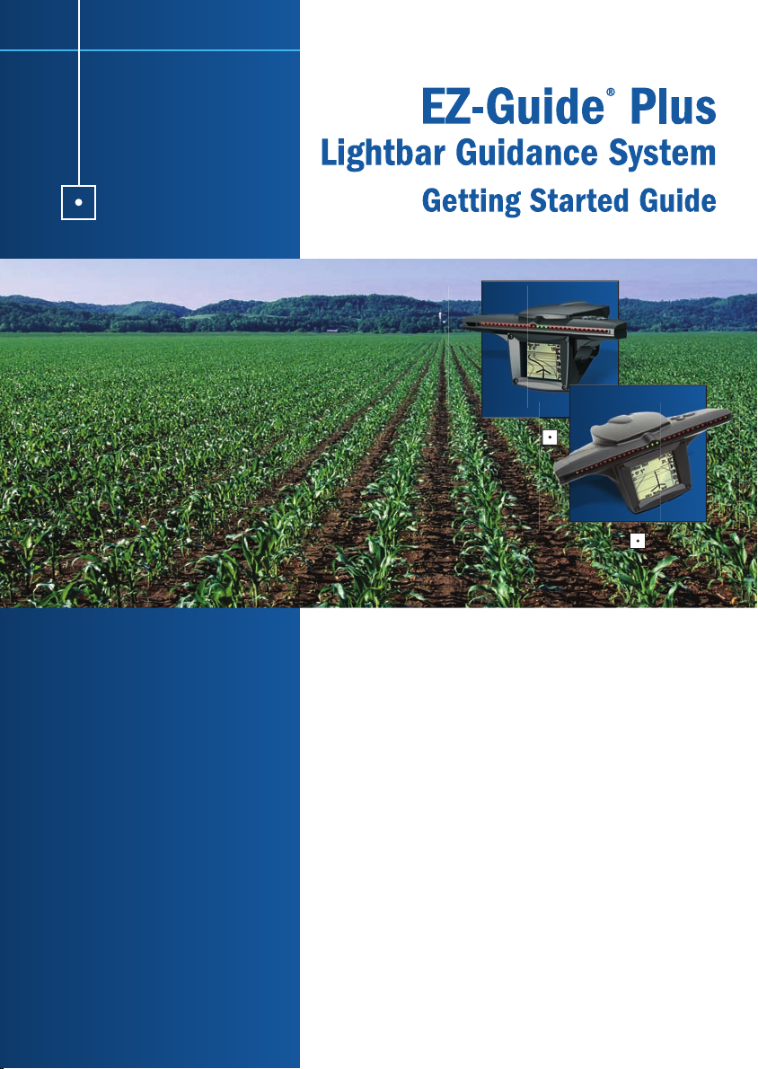
What’s in the EZ-Guide Plus box?
When you receive your EZ-Guide Plus system, check that you have received all the
components, as detailed on the packing list. The following diagram shows the
standard components.
EZ-Guide Plus
lightbar
Antenna cable
Antenna
Magnetic mount
Metal plate
Quick Reference Card
AgGPS® EZ-Guide® Plus Lightbar
Guidance System Quick Reference Card
CONNECTING THE SYSTEM
Standard system
®
AgGPS
EZ-Guide®Plus
Lightbar Guidance System
Getting Started Guide
Optional EZ-Boom™ 2010 automated application
control system
58378R REV 1
DCA 0615
CAUTION —
Keep the lightbar dry. Do not spray it with any type of liquid as this may cause it to fail.
www.trimble.com
www.trimble.com
Getting Started Guide
Optional remote control
Optional T2™ terrain compensation
technology
Optional EZ-Steer
steering system
www.EZ-Guide.com
®
assisted
Lightbar
power
Lightbar
bracket
and bolts
Null modem cable
Mounting pad
Lightbar suction
cup mount
cable
Note — The antenna is included if the lightbar has an integrated GPS receiver.
EZ-Guide Plus Lightbar Guidance System Getting Started Guide Introduction 9
Page 12
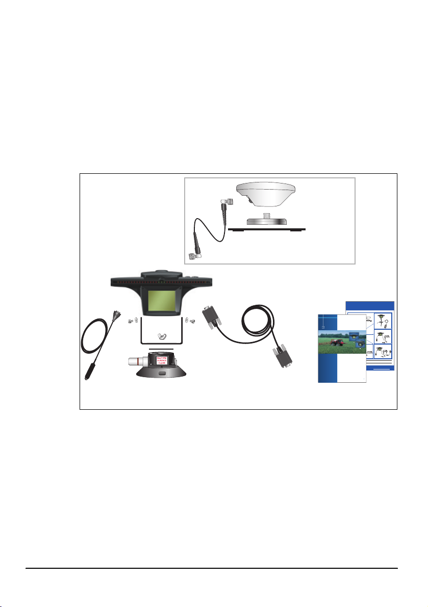
Optional accessories and upgrades
The following optional accessories and upgrades are available:
Component Example
Remote control kit
External interface cable
RAM mount bracket
EZ-Steer® assisted steering system upgrade
EZ-Steer controller with T2™ terrain
compensation technology
EZ-Boom™ 2010 automated application
control system
58378R REV 1
DCA 0615
AgGPS® Autopilot™ automated steering
system upgrade + platform kit
radar cable kits
10 Introduction EZ-Guide Plus Lightbar Guidance System Getting Started Guide
Page 13

For more information and ordering details, contact your local reseller.
C
CAUTION — Keep the lightbar dry. Do not spray the lightbar with any type of liquid as
this will cause it to fail.
Inspect all contents for visible damage, such as scratches or dents. If any
components appear damaged, notify the shipping carrier. Keep the shipping and
packaging material for the carrier’s inspection.
Installing the system
1. Assemble the bracket kit. The bracket is reversible to optimize it for roll angle. For
more information, refer to the instructions in the bracket kit.
2. Attach the suction cup to the bracket.
3. Attach the power cable to the lightbar.
4. Mount the lightbar in the required position on the window. See
lightbar, page 11
5. Attach the antenna to the magnetic mount.
6. Connect the antenna cable to the antenna and route the cable to the cab.
7. Attach the magnetic mount to the cab roof, along the vehicle centerline. Do one
of the following:
– If the cab roof is steel, attach the magnetic mount directly to the roof.
– If the cab roof is not steel, attach the metal plate to the cab roof. Then
attach the magnetic mount to the metal plate.
8. Connect the antenna cable to the lightbar.
9. Plug the power cable into the vehicle cigarette lighter. See
cigarette lighter, page 12
Mounting the
.
Using the vehicle
.
Mounting the lightbar
C
EZ-Guide Plus Lightbar Guidance System Getting Started Guide Introduction 11
CAUTION — The suction cup mount is a temporary mounting device. Before you use
it, read the manufacturer’s instructions provided with the mounting kit.
1. Dampen the rubber seal on the suction cup.
2. Place the suction cup on a clean section of window, and then pump the plunger
until its red line is no longer visible.
In addition:
• To ensure that the lightbar stays securely attached, pump the suction cup each
day, or whenever the red line appears on the plunger.
• If the lightbar does not stay securely attached with the suction cup, you can glue
the cup to the window. Or, attach the lightbar bracket directly to the dashboard,
ceiling, or window.
Page 14
Using the vehicle cigarette lighter
If the power cable is plugged into a cigarette lighter that is not wired through the
vehicle ignition, the lightbar receives power whenever the cable is plugged in. To avoid
draining the vehicle battery, turn off or disconnect the lightbar from the power source
if the vehicle will be unused for an extended time.
Minimizing GPS signal interference
To minimize any interference to the GPS signal, make sure that the GPS antenna is at
least 1 m (3 ft) from any other antenna (including a radio antenna), and at least
100 m (300 ft) from any power line, radar dish, or cell phone tower.
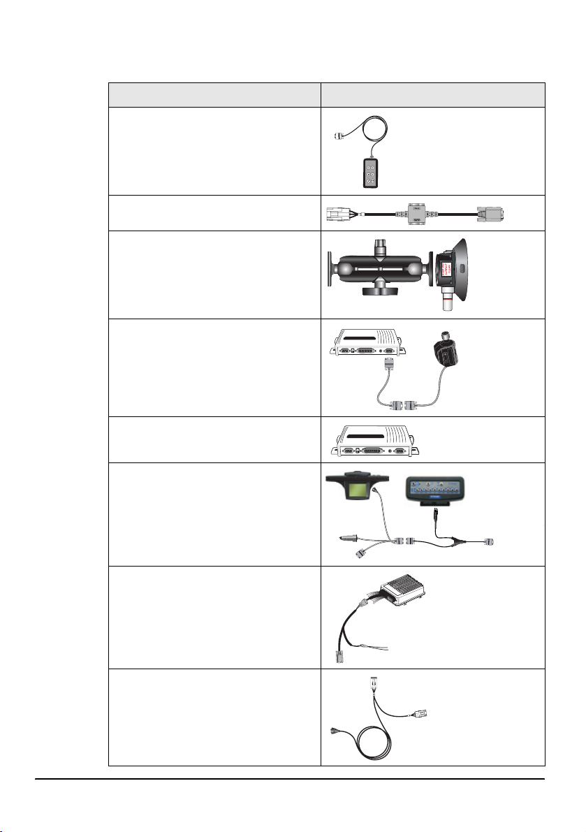
Connecting to other devices
• To use the remote control or an external GPS receiver or an external sensor (for
example, yield monitor), attach it directly to the lightbar data port connector.
• To use the remote control and an external
receiver or sensor, connect them using
the optional external interface cable.
Note — You cannot connect an external
GPS receiver and external sensor at the
same time.
• To connect a spray switch or device to
receive speed pulse outputs, use the
optional external interface cable
.
For information on configuring the data port settings, see Using GPS, page 41.
To GPS
or external
sensor
Switch input
or pulse output
12 Introduction EZ-Guide Plus Lightbar Guidance System Getting Started Guide
Page 15
Getting Started
This section describes the parts of the EZ-Guide Plus lightbar guidance system and
how to configure it. For information on using guidance patterns, see
page 13
.
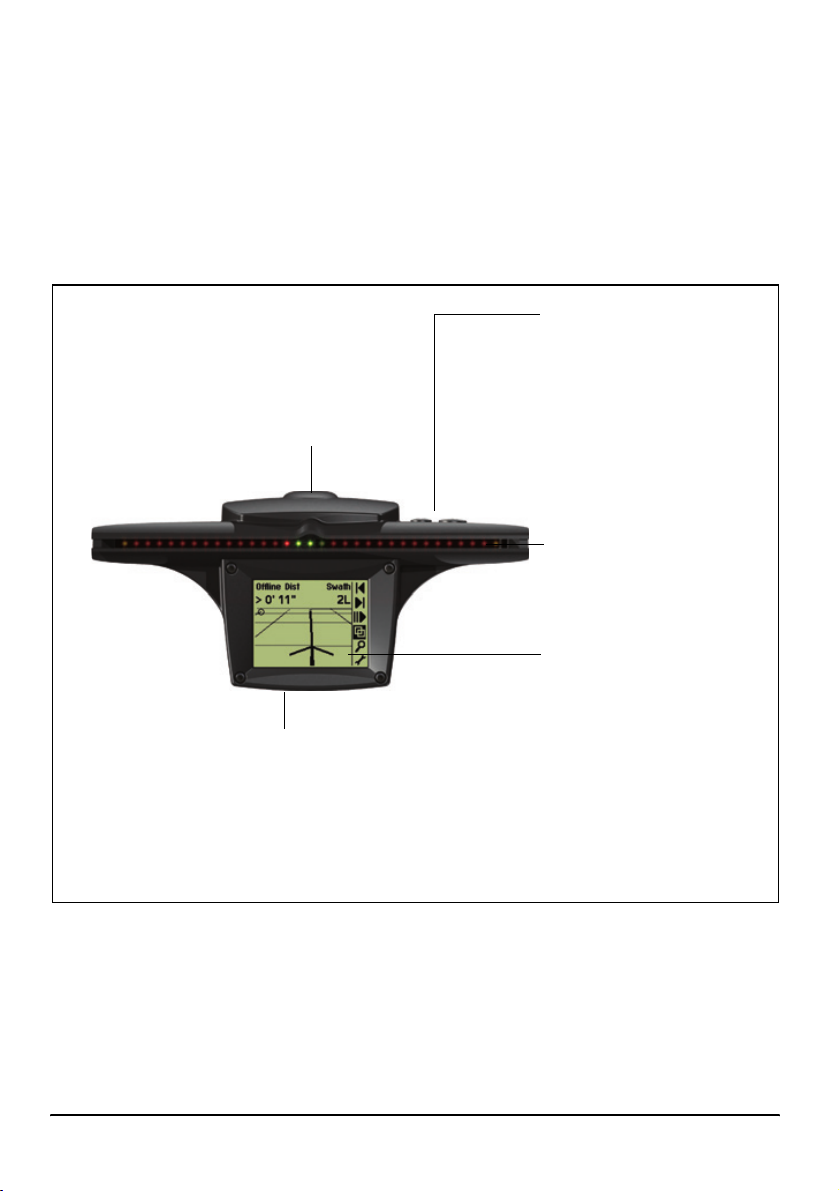
Parts of the EZ-Guide Plus lightbar
Integrated GPS receiver (optional)
• High-performance
• Integrated WAAS/EGNOS/MSAS receiver
• EVEREST™ multipath rejection
technology
Data port
• GPS output
• External GPS input
• External correction input
• GPS diagnostics and configuration
• Pulse output and switch input (requires external interface cable)
Getting Started,
Three Buttons
• o Action selects icon,
accepts changes
u Selects icon, increase
•
configuration value
D Selects icon, decrease
•
configuration value
Guidance LEDs
Provide offline guidance to the
closest swath
LCD display
• Monochrome
• Anti-glare screen
• Multi-level backlight
EZ-Guide Plus Lightbar Guidance System Getting Started Guide Getting Started 13
Page 16
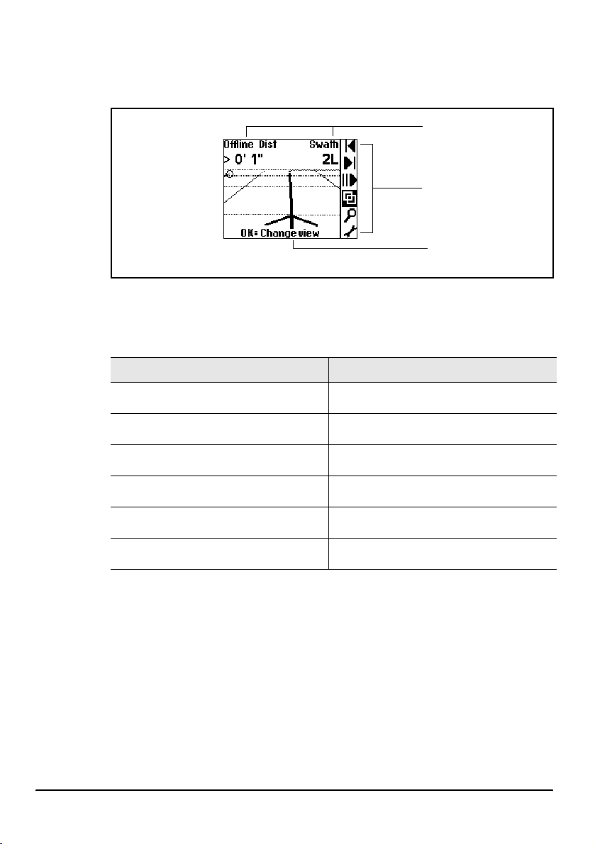
Using the lightbar
Items on the main map screen
Action icons
To select an icon, press u or D, and then press o. These action icons can be
displayed in the icon bar:
Icon Description Icon Description
9
Reset guidance
Status text
Action icon bar
Tips
1
Nudge left
A
B
8
D
7
Note — Some action icons may not be available until a field is defined.
14 Getting Started EZ-Guide Plus Lightbar Guidance System Getting Started Guide
Set Point A
Set Point B
Start headland
Final headland
Go to main configuration menu
3
2
4
5
Nudge right
Pause/Resume
Change views
Zoom
Page 17
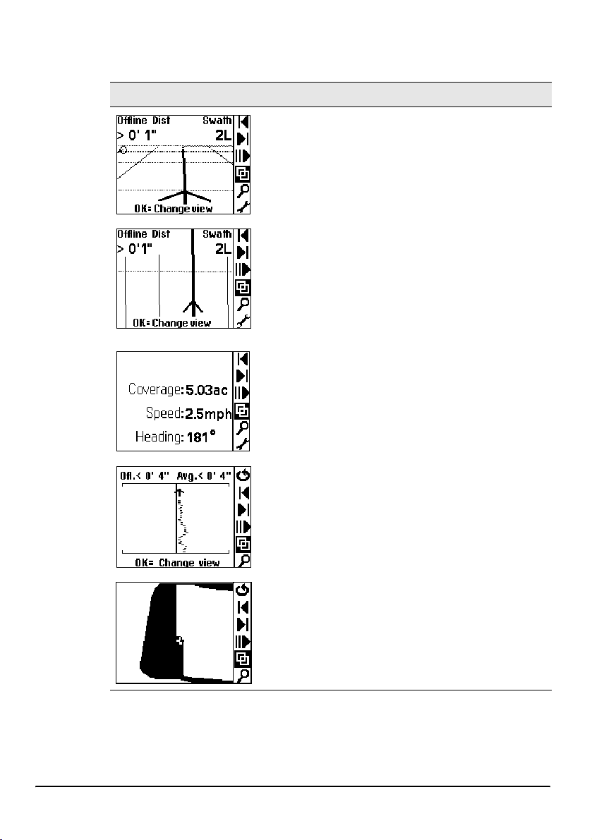
Views
To change between the four views, select 4.
View Details
Perspective map
This is the default screen for guidance.
It displays two status text options.
Plan map
This is the default screen when you:
• define the field
• pass the end of the swath
• move offline by more than half a swath
• pause guidance
It displays two status text options.
Status
This screen displays up to four status text options.
To configure the text, use the Status Text configuration
option.
Offline
This screen displays the vehicle offline error for the last 10
seconds. This view is not available until you have defined a
field.
Summary
This screen displays covered area. It allows you to see any
skips or overlaps in material application.
To zoom in on or move the Summary view, select the
5 icon.
EZ-Guide Plus Lightbar Guidance System Getting Started Guide Getting Started 15
Page 18
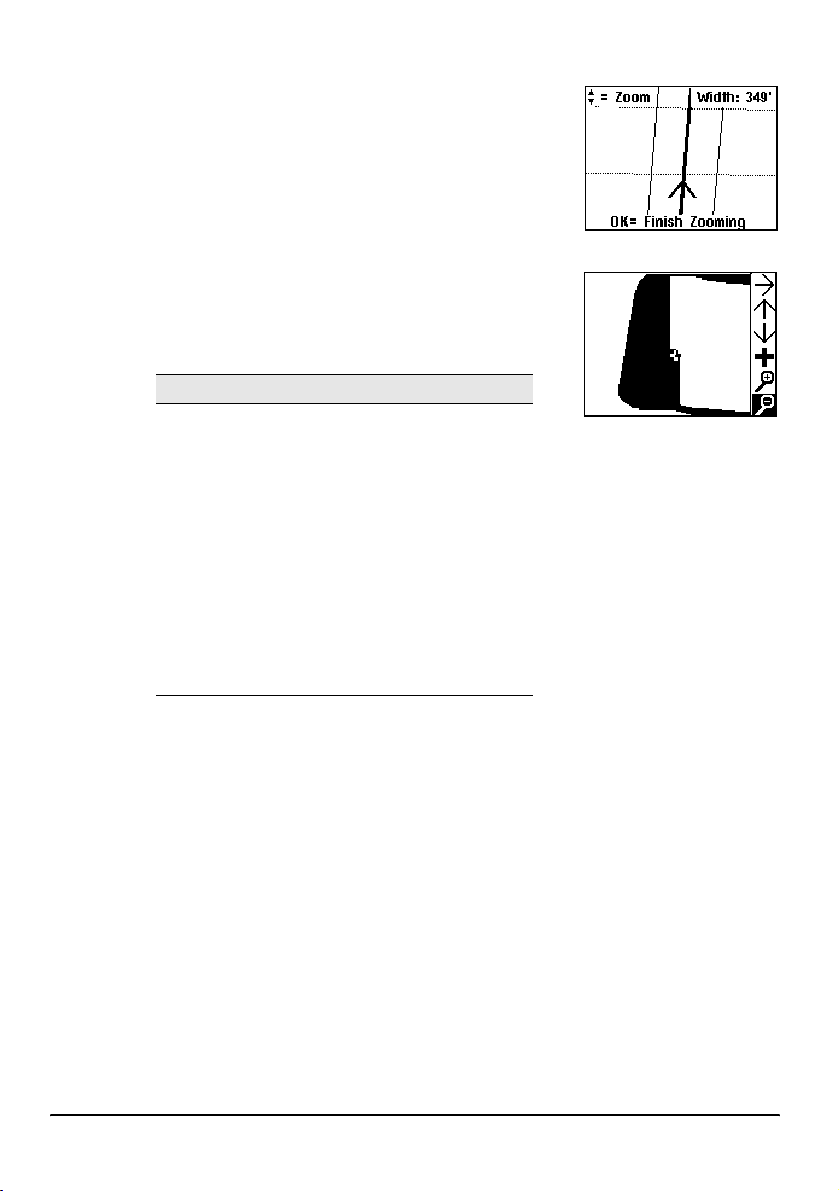
Zooming
To enter zoom mode, select 5, or press z on the
remote control. The zoom screen appears.
• To change the zoom scale, press
• To accept the zoom scale and return to the map
view, press
Zooming in the Summary view
In the Summary view, there are additional zoom
features. To access the additional features, when you are
in the Summary view press
icons appears:
Action icon Description
5
I
J
K
L
+
o, or press z on the remote control.
5. A different set of action
End zoom mode
Move view left
Move view right
Move view up
Move view down
Center view on the vehicle
Zoom view in
Zoom view out
u or D.
Configuring the lightbar
Before you use the lightbar in the field, check and configure the lightbar settings from
the Lightbar menu:
1. To access the configuration menu, do one of the following:
• Select
• Press
2. To select a configuration option and display the value, press
the setting, press
3. To change the value, press
4. To exit the configuration menu, do one of the following:
• Press
• Press
16 Getting Started EZ-Guide Plus Lightbar Guidance System Getting Started Guide
7 and then press o.
m on the remote control.
u or D. To accept
o.
u or D. To save the change, press o.
u or D until you have selected the Return to Guidance option, and
then press
o.
m on the remote control.
Page 19
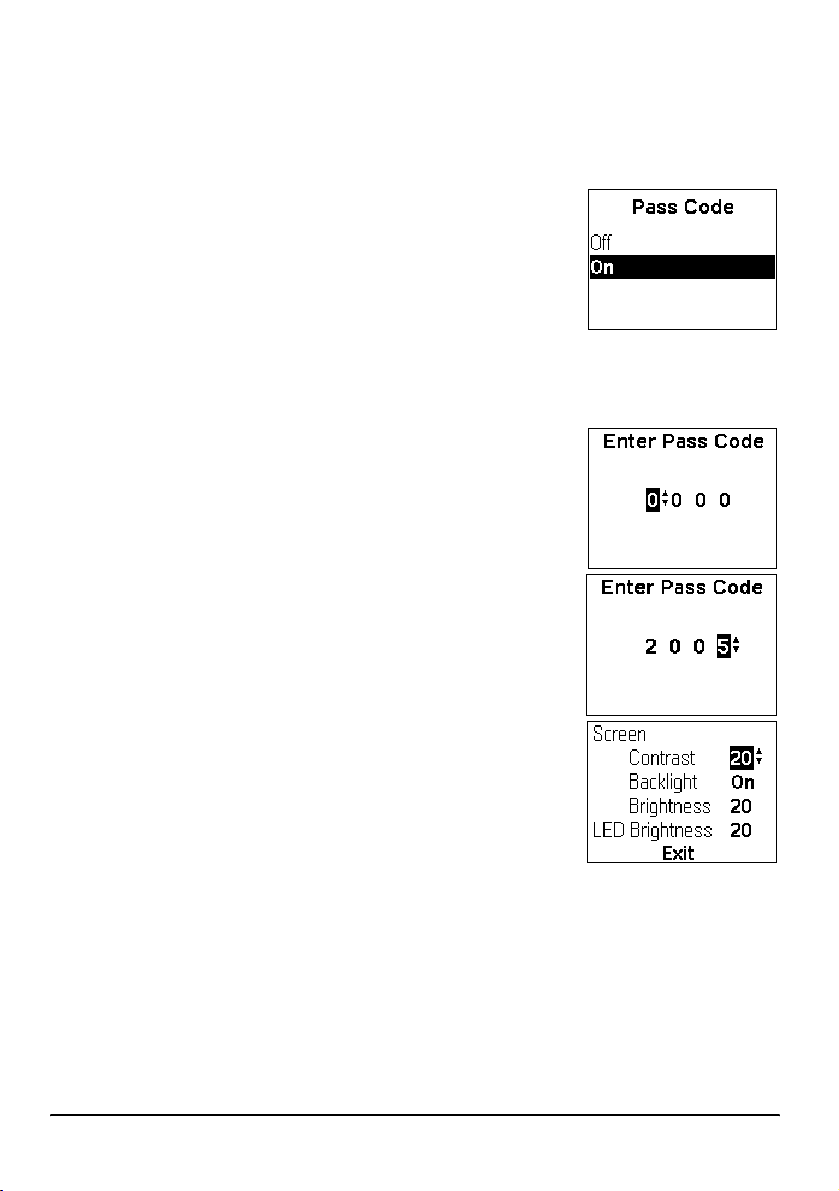
Pass code restriction
The EZ-Guide Plus lightbar has a pass code option that protects the lightbar
configuration settings from being accessed and modified.
Enabling or disabling the pass code
1. From the configuration menu, select Pass Code. The
Pass Code screen appears.
2. Press
If the Pass Code option has been set to On, then you are
prompted to enter the Pass Code when you select
Pass Code entry
The correct Pass Code is "2005". To enter the code when
the Enter Pass Code screen appears:
1. Press
2. Press
3. Repeat Steps 1 and 2 until all four digits are correct.
If you enter the wrong code, you are returned to the main
screen.
u or D to select the required option and then
press
o.
You are returned to the main menu.
u or D until the correct digit appears in the
column.
o to select the next column.
7 or press m.
Adjusting the brightness and contrast
You can view the LCD screen in all conditions—from bright
sunlight to night time.
If necessary, use Lightbar / Contrast / Brightness to
adjust the screen contrast, turn on the backlight, or adjust
the backlight and LED brightness.
The lightbar retains its backlight setting even if the lightbar is reset to the default
settings.
B
EZ-Guide Plus Lightbar Guidance System Getting Started Guide Getting Started 17
Tip — If the backlight is configured to On, it automatically turns off during daylight
hours, and turns back on in the late afternoon. When the backlight is enabled but
currently not on, the Backlight setting displays Auto.
Page 20
Setting the units and language
By default, the units are set to US and the language is set to English. To change:
• the units to metric, select Lightbar / Units
• the language to Portuguese, Spanish, French, German, or Italian, select
Lightbar / Language
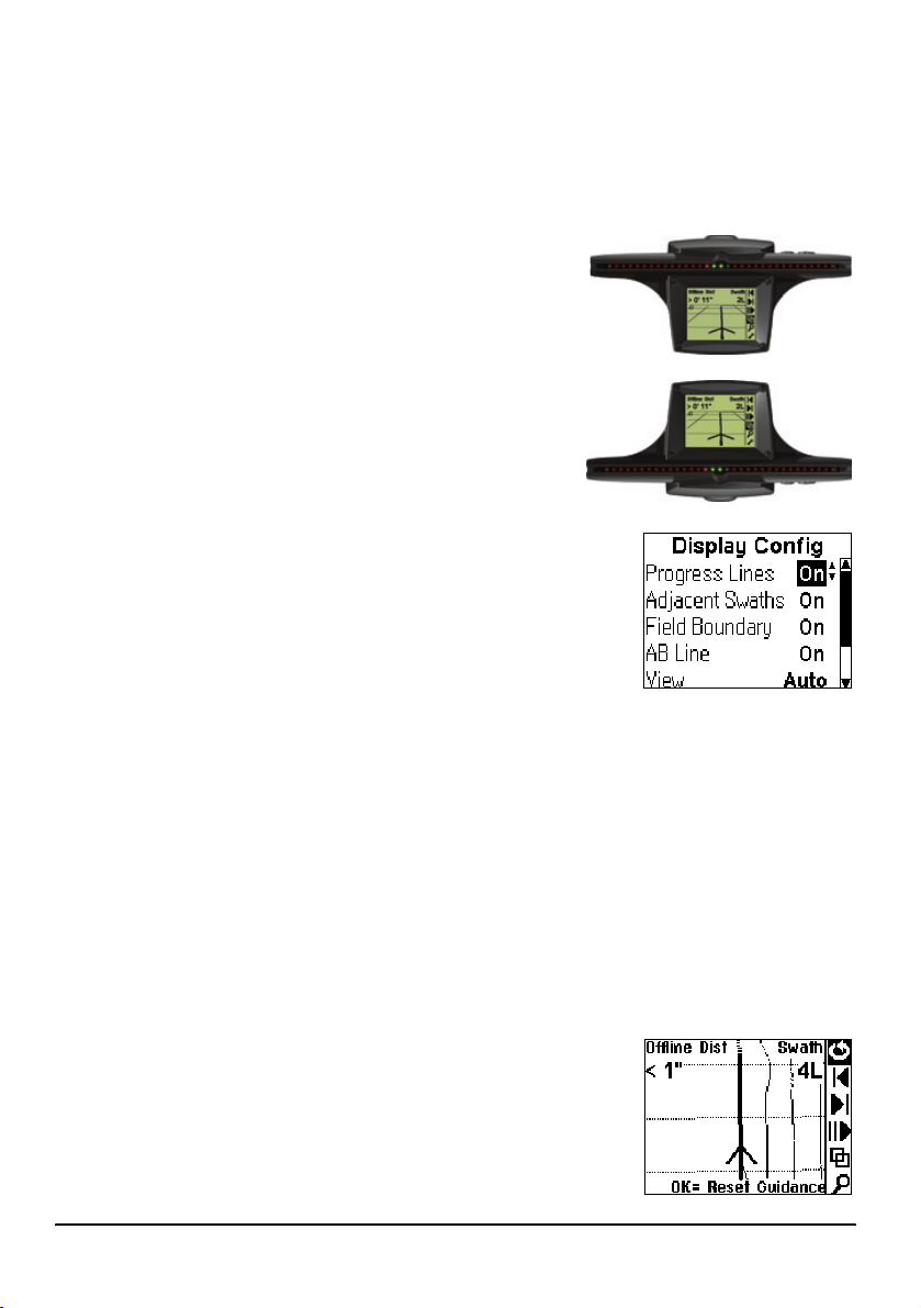
Changing the display orientation
Generally, mount the lightbar with the LEDs above
the screen (upright). If you mount the lightbar with
the LEDs below the screen (inverted), select
Upright
Lightbar / Lightbar Mount and change the setting.
Inverted
Configuring the display
Select Lightbar / Display Config to enable or disable any
of the following items displayed on the plan and
perspective maps. Set:
• Progress Lines to On to give a sense of perspective
and speed.
• Adjacent Swaths to On to display one swath either
side of the current swath.
• Field Boundary to On if the field is a Headland.
• AB Line to On to display the AB Line.
• Path Display to the relevant option to display the path driven. See
the Summary screen, page 19
.
You can also use this screen to change the View option:
• Auto: The view automatically changes between plan and perspective views in
headlands
• Fixed: The view remains fixed
Path Display on
Path Display on the Map and 3D screen
By default, the path you have driven is always displayed
on screen as a dotted line.
18 Getting Started EZ-Guide Plus Lightbar Guidance System Getting Started Guide
Page 21
Path Display on the Summary screen
The following table shows the effect of the Path Display settings on the Summary
screen:
Item Description
Off Coverage is not displayed
On Coverage is displayed wherever the vehicle drives
Switch Coverage is displayed when it is enabled by an external switch
Engaged Coverage is displayed when the EZ-Steer system is engaged
EZ-Boom Coverage is displayed where the EZ-Boom 2010 system sprayed
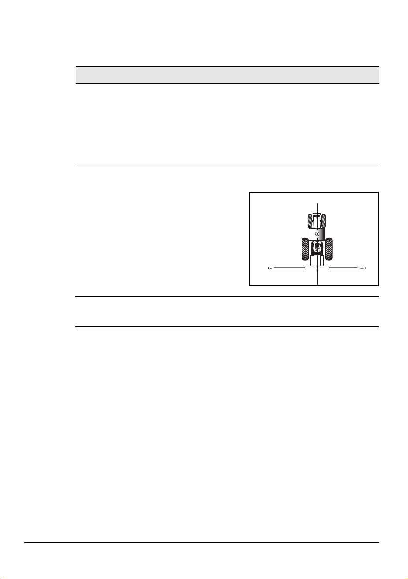
Setting the antenna offset
By default, the antenna is assumed to be at the
implement position. If the antenna is not
mounted at the implement position, to ensure
correct guidance, set an antenna offset using
Lightbar / Ant/Impl. Offset.
Antenna offset
ahead of
implement
Vehicle centerline
Implement
C
CAUTION — The antenna must be mounted on the vehicle centerline. Otherwise,
offline guidance will not be correct.
Coverage area
Coverage area is calculated whenever the spray switch is connected and on. For
information on connecting a spray switch, see
By default, Coverage Area is displayed on the Status screen. To display Coverage Area
on a map view instead, select Lightbar / Status Text.
B
EZ-Guide Plus Lightbar Guidance System Getting Started Guide Getting Started 19
Tip — To save the coverage area value, you must Pause before turning off the
system. Otherwise the value will be lost when you restart the system.
If you load an existing AB Line with a coverage area value, you can choose to add to
the value, or reset to 0.
Connecting to other devices, page 12.
Page 22

Status text
The Plan Map, Perspective Map, and Status views display four status text items. The
Plan Map and Perspective Map views show two of the status text items at the top of
the screen, which then change to the other two items. The status text items cycle
every three seconds. The Status screen shows all four items at once.
Status text item Definition
Swath Number Swath number of the closest swath.
Offline Distance Distance offline from the closest swath.
Speed Current speed.
Heading Current heading.
Field Area Area of the field calculated half a swath width outside the path driven. A
value is displayed only for Headland patterns.
Mapped Area The size of a mapped area, in acres (US) or hectares (metric).
Satellites Number of GPS satellites used.
HDOP Horizontal Dilution of Precision. This is a measure of accuracy based on
the geometry of the satellites in the sky. An HDOP of 2 or less is good.
Height Current antenna height above mean sea level (MSL).
GPS Status Current GPS status.
XP/HP status (Convrg./Unconvrg.) (If you use OmniSTAR XP/HP with an
optional high accuracy receiver.)
Correction Age The age of the GPS signal.
Coverage Area Area applied while spray switch was on or sprayed using the EZ-Boom
system. Calculated as distance x swath width. To save the coverage area
value when turning off the system, pause guidance before disconnecting
power.
Nudge Displays accumulated nudge perpendicular to the direction of travel.
Yaw Rate The speed of change in yaw.
Roll Rate The speed of change in roll.
Overlap The current amount of spray overlap (positive value) or skip (negative
value).
TRate Application target rate: Shows which rate is selected (Rate1, Rate2, or
Manual) and the target rate.
Pressure The current spray system pressure.
Pressure B The second pressure sensor.
20 Getting Started EZ-Guide Plus Lightbar Guidance System Getting Started Guide
Page 23

Status text item Definition
Current Rate The current rate (gal/Ac or L/ha).
Current Flow The current flow (gal/min or L/min).
Applied Volume Total volume (gal or L) applied.
Tank Volume The current volume of product in the spray tank (gal or L).
Swath Pts The number of points in the current swath.
Swath Len The length of the current swath.
Conv Dist XP/HP convergence distance.
Roll The roll angle of the vehicle.
Field Num ID# of the AB Line.
None No status text is displayed.
Stopping the status text from cycling
To stop the Status Text from cycling in the Plan Map and Perspective Map views, set
the:
• first and third status items the same
• second and fourth status items the same
EZ-Guide Plus Lightbar Guidance System Getting Started Guide Getting Started 21
Page 24

22 Getting Started EZ-Guide Plus Lightbar Guidance System Getting Started Guide
Page 25

Getting Guidance
The EZ-Guide Plus lightbar guidance system provides the following pattern options:
Pattern Definition
AB Line Straight guidance based on A and B points that define the initial line.
A+ Straight guidance based on an A point and the previous line heading.
Identical curve Curve guidance based on the initial curve.
Adaptive curve Curve guidance based on the last curve driven.
Headland Records headlands of any shape as you drive around the field. Can
provide guidance on multiple headland passes and straight swath
guidance inside the headlands.
Center-pivot Curve guidance in a center-pivot field.
Row finder When you drive with an implement that spans several rows, the system
guides you to the next appropriate swath without having to count the rows
in between yourself.
Area Mark out an area to show obstacles/excluded areas, calculate the size of
an area, or to display an area onscreen.
Select Stored AB Select and load a previous AB Line.
Delete Current AB Delete the current AB Line.
Delete all ABs Delete all saved AB Lines
For more information, see
Using guidance patterns, page 24.
Note — If you are using WAAS corrections and the system has been turned off for
more than 2 hours, a warning appears when the first WAAS DGPS position is
received. For best accuracy, wait for 10 minutes after receiving the WAAS DGPS
warning before you set an AB Line or select a stored field.
Note — If you are using a receiver with RTK or OmniSTAR XP/HP corrections, do not
define a new guidance line until the Low Accuracy message stops flashing.
Otherwise, you may get significant pass-to-pass drift until the receiver reaches its
highest level of accuracy (Fixed or Convrg.).
If the GPS Status is Float or Unconvrg.,
the accuracy is still converging.
EZ-Guide Plus Lightbar Guidance System Getting Started Guide Getting Guidance 23
Page 26

Resetting guidance
1. Select 9. The Guidance Pattern screen appears.
2. Press
3. To confirm, press
u or D to choose the required pattern and
then press
A message appears asking you to confirm your
choice. This prevents accidental resetting of the
guidance pattern.
o.
o.
Configuring the swath width
Once you select a pattern, the Swath/Implement screen
appears.
To change the swath width value:
1. Select the Swath Width field.
2. Press
3. Press
u or D until the correct value is displayed.
o.
B
B
Tip — To avoid skips between swaths, set the swath width to 0.3 m (1 ft) less than
the total implement width.
If the vehicle has an implement that is offset to one side of the vehicle, configure an
implement offset:
1. Select the Impl. Offset field.
2. Press
3. Press
Tip — If an implement offset is configured, the guidance arrow will represent the
center of the implement, instead of the center of the vehicle.
Note — In some adaptive curves, tight U-turns with an implement offset may not be
detected if the implement does not follow the path of a U-turn. If this occurs, set
Guidance / Auto-detect Turn to Off, manually set B, and then turn onto the next
curve.
u or D until the correct value is displayed.
o.
Using guidance patterns
This section describes how to define and use each of the available guidance patterns.
The AB Line is a line that runs between Point A and Point B, although you may not
always set a Point B. In most cases, the AB Line is the reference line for subsequent
swaths.
The start and end of the initial swath that defines the swath pattern appear on the
lightbar screen as a circle (Point A) and a square (Point B).
24 Getting Guidance EZ-Guide Plus Lightbar Guidance System Getting Started Guide
Page 27

Swaths drawn on screen extend 1 km (0.62 mi) beyond Point A and Point B, and the
extensions appear as dotted lines. This makes it easier to see where the next swath is,
and to get online after the turn.
Note — The initial swath (AB Line) appears as a thin, solid line; the current swath
appears as a bold line.
AB Line pattern
Use the AB Line pattern when no headlands are
required and you drive the field in parallel straight
lines.
1. At the start of the first swath, map Point A.
2. Drive to the other end of the field, and at the
end of the first swath, map Point B.
Step 2
B
Step 1
A
B
Tip — Set Point B part way down the swath to get guidance down the first pass, and
then reset Point B at the end of the field.
3. Turn left or right for the next swath. The next swath is automatically selected.
4. Steer the vehicle so that you center the green lights in the lightbar as you drive
forward along the swath.
Note — On straight AB Lines, if you complete a swath that is longer than the
previous one, the EZ-Guide Plus system automatically extends the guidance
path for the following swaths so that headland warnings do not appear
prematurely.
A+ pattern
Use the A+ pattern when you need guidance exactly parallel to the last AB Line, for
example when:
• driving adjacent fields
• mapping the AB Line on a road down the side of the field
• skipping an access road in a field
1. To map the start of the first swath, map
Point A.
The heading of the AB Line equals either the
previous AB heading or the manually
entered heading (if the current vehicle
heading is within ±90 degrees of the AB
heading). Otherwise the A+ heading is in the
opposite direction.
Last
AB Line
Step 1
A
EZ-Guide Plus Lightbar Guidance System Getting Started Guide Getting Guidance 25
Page 28

2. Follow the AB Line for guidance down the first swath.
3. Turn left or right for the next swath. The next swath is automatically selected.
4. Steer the vehicle so that you center the green lights in the lightbar as you drive
forward along the swath.
Identical curve pattern
Use the Identical curve pattern when you want to work the field with gentle curves.
This pattern provides guidance based on the initial curve. It ignores any deviation
around an obstacle.
1. At the start of the first swath, map Point
A.
2. Drive the initial curve. At the other end
of the first swath, map Point B.
3. Turn left or right for the next swath. The
next swath is automatically selected.
4. Steer the vehicle so that you center the
green lights in the lightbar as you drive
forward along the swath.
Note — Guidance extends beyond the end of curved swaths. This makes it
possible to get LED guidance back onto the swath if the vehicle drives past the
end of a swath. The extended swath lines do not appear on screen.
Step 1
A
B
Step 2
Obstacle
Adaptive curve pattern
Use the Adaptive curve pattern to follow gentle contours in the field, or when you need
to avoid obstacles. This pattern provides guidance based on the last curve driven.
Note — By default, the end of the swath is automatically detected when you do a
U-turn. If you prefer to manually mark the end of each swath, from the main menu,
select Guidance / Auto-detect Turn and change the setting to Off. You must then
reset Point B at the end of every pass, to mark the end of the swath before you start
the turn.
26 Getting Guidance EZ-Guide Plus Lightbar Guidance System Getting Started Guide
Page 29

Simple curves (using Adaptive curve pattern)
To drive simple Adaptive curves with the default of Auto-detect Turn set to On:
1. At the start of the first swath, map
Point A.
2. Drive the initial curve.
3. Turn left or right for the next swath. The
next swath is automatically selected.
4. Steer the vehicle so that you center
the green lights in the lightbar as you
drive forward along the swath.
C-clamp (using Adaptive curve pattern)
To use the Adaptive curve pattern to get C-clamp guidance with the default of
Auto-detect Turn set to On:
1. At the start of the headland, map
Point A.
2. Drive around the headland in a C-clamp
pattern.
3. Turn left or right for the next swath. The
next swath is automatically selected.
4. Steer the vehicle so that the green lights
in the lightbar are centered as you drive
forward along the swath.
Note — The bold lines in the figure show
where you must drive without guidance.
Step 1
A
Obstacle
Step 1
A
Spiral (using Adaptive curve pattern)
To use the Adaptive curve pattern to get spiral guidance into the center of the field:
1. From the Guidance menu, set Auto-
detect Turn to Off.
2. Start a new field using the Adaptive
Curve pattern.
3. At the start of the headland, map
Step 3
Step 5
A
B
B
B
BB
Point A.
4. Drive around the headland.
5. When you are nearly back at Point A,
map Point B.
EZ-Guide Plus Lightbar Guidance System Getting Started Guide Getting Guidance 27
Page 30

Note — Make sure that you are not within one swath width of the start point. If
you are, Point B will not be set.
6. Turn into the field. The next swath is generated off the last pass.
7. On each pass, when you are nearly back to where you started the headland, reset
Point B to mark the end of the swath.
Rowfinder (using Adaptive curve pattern)
When you drive with an implement that spans several rows, you can navigate to the
next appropriate swath without having to count the rows in between yourself.
To use the Adaptive Curve pattern to count the rows that you can skip:
1. Select Guidance / Auto-detect Turn and set
Auto-turn to Off.
2. Reset guidance and then select the Adaptive Curve
pattern.
3. Select the Swath Width value that matches the
width of your implement.
4. Mark Point B at the end of the row.
5. Find the next row to drive down by turning until you
see three green LEDs on the lightbar.
A
B
B
B
B
B
Headlands pattern
Use the Headlands pattern when:
• you need to apply the headland area first, to give you room to turn when you apply
the straight swaths
• you want to know the area of the field
You can do as many headland circuits as required before you change to straight
swaths. The Headlands pattern automatically increments to the next headland when
you enter the circle around the start point of the headland.
Tip — To pause, zoom, or change the headland view, click the appropriate icon.
Multiple headlands
1. Start a headland.
2. Drive around the field area. The headland is
recorded.
3. When you return to the headland start point,
the next headland swath is automatically
generated.
Step 1
8
Step 4
D
Step 5
A
Step 6
B
28 Getting Guidance EZ-Guide Plus Lightbar Guidance System Getting Started Guide
Page 31

4. On your final headland, press D before you return to the circle. This stops the
lightbar from generating a new headland swath and allows you to map A and B
points.
You continue to receive guidance to the final headland until you drive off the pass
by half a swath.
5. To map the start of the first straight swath, map Point A at any time.
6. Drive to the other end of the field and then map Point B.
Note — Straight swaths automatically fill the headland boundary. The AB Line
does not need to be the full length of the field.
B
Tip — The Headland pattern displays the edge of the innermost headland.
7. Turn left or right for the next swath. The next swath is automatically selected.
8. Steer the vehicle to center the green lights in the lightbar as you drive forward
along the swath.
Note — The IN HEADLAND! warning only appears if your antenna offset is set to
0. If your antenna offset is greater than 0, you can achieve a similar effect by
setting the Headland warning lead time to greater than 0 (for example,
3 seconds). The HEADLAND! warning will then appear before the headland is
reached.
Single headland
1. Start the headland.
2. Start driving around the field area. The
headland is recorded.
3. After a short distance, identify the current
headland circuit as the final one.
Note — Do this before you enter the circle
around the start point or map A and B points.
The headland is still recorded until you reach
the circle around the start point.
4. To map the start of the first straight swath, map Point A.
5. Drive to the other end of the field and map Point B.
Note — Straight swaths automatically fill the headland boundary. The AB Line
does not need to be the full length of the field.
6. Enter the circle around the start point of the headland to complete the headland.
The area is then displayed.
7. Turn left or right for the next swath. The next swath is automatically selected.
Step 1
8
Step 6
Step 3
D
Step 4
A
Step 5
B
EZ-Guide Plus Lightbar Guidance System Getting Started Guide Getting Guidance 29
Page 32

Steer the vehicle to center the green lights in the lightbar as you drive forward along
the swath.
Center-pivot pattern
Use the Center-pivot pattern for a field that is irrigated using a center-pivot. With this
pattern, you can drive concentric circles around the center-pivot.
1. Position one wheel of the vehicle in a pivot wheel
rut, with the rear of the vehicle to the pivot arm. If
the field is not a full circle pivot, face the rear of the
vehicle to the edge of the field.
2. To start the pivot, map Point A.
3. Drive around the field. Keep the vehicle wheel in the
rut. The lightbar does not yet provide guidance.
4. When you are almost back to the pivot arm or the edge of the field, map Point B.
The EZ-Guide Plus lightbar generates guidance swaths.
5. Turn left or right for the next swath. The next swath is automatically selected.
6. Steer the vehicle so that you center the green lights in the lightbar as you drive
forward along the swath.
Note — To work from the center of the field outwards, the initial pivot must have:
• a radius of at least two swath widths
• an arc length of at least two swath widths
A
B
Row Finder pattern
The Row Finder pattern makes it easy to find the correct
row to drive down after you make a turn. It is based on
the Adaptive Curve pattern.
1. Set the swath width and implement offset.
2. Set the A point.
3. Drive the first swath.
4. When you reach the end of the row,
manually set the B point at the end of
the row. The swath number will appear
in the top right corner of the screen.
5. Repeat Step 4 for each successive
swath.
6. Use the offline LEDs and screen to
turn onto the next swath.
B
30 Getting Guidance EZ-Guide Plus Lightbar Guidance System Getting Started Guide
Tip — Row Finder guidance works on straight or curved rows.
Step 1
A
B
B
B
B
B
Obstacle
Page 33

Mapped area
With area mapping you can:
• map area features
• mark out an obstacle or excluded area
• Calculate the number of acres/hectares
• display the area onscreen while receiving guidance
To map an area:
1. From the main screen, select 9. The Guidance Pattern screen appears.
2. Select New Area. The Map Area At screen appears.
3. Select the point on the vehicle from which the
measurement will be taken (right end of implement,
left end of implement, or antenna).
The main screen appears.
4. Select 8 to begin mapping the area. The Mapped
Area value continuously updates. It appears on the
map screen as you drive around the boundary of
the area.
5. Select D or drive back into the start/finish circle to
end area mapping.
The mapped area will remain onscreen until the
next time power is switched off. Mapped areas are not saved if the power is
switched off.
The previously selected AB Line/curve/headland is automatically reloaded after
you finish mapping the area. Only one area can be shown at a time.
The EZ-Guide Plus system does not allow guidance around the mapped area.
If necessary, you can use the pause function to pause mapping to drive around
obstacles. When you select the pause/resume icon, a straight line is drawn between
the pause and resume points.
Saving, loading, and deleting AB Lines
The EZ-Guide Plus system can save, load, and delete AB Lines.
Saving AB Lines
The EZ-Guide Plus system can save up to 96 straight swaths or pivots, and up to 3
curve or headland swaths. The system automatically saves the last AB Line. When you
have saved more than the permitted number of AB Lines, the AB Lines that have not
been used for the longest time are overwritten.
EZ-Guide Plus Lightbar Guidance System Getting Started Guide Getting Guidance 31
Page 34

Loading an existing AB Line
1. Select 9 to reset guidance. The Guidance Pattern
screen appears.
2. Select Select AB Line and then press
o. The
Select AB Line screen appears.
3. Press
u or D to adjust the range of AB Lines to
select from and then press
o.
The Select Stored AB screen appears. It displays
all saved AB Lines within the range you selected.
The position of the vehicle is shown as a cross with
a dot in the middle. The currently selected AB Line
or curve is displayed with thicker bold lines.
The number of the current line is shown in the
middle of the bottom of the screen. Positions 1–3
are used for headlands and curves. The first straight AB or pivot will be number
4.
4. Press
u or D to select the correct AB Line and then press o. The
Swath/Implement screen appears.
5. Set the swath width and the implement offset.
6. Select Exit and then press
o.
The system loads the line.
Deleting the current AB Line
1. Select 9. The Guidance Pattern screen appears.
2. Select Delete Current AB. The Confirmation screen
appears.
3. Select Continue. The Guidance Pattern screen
appears.
4. Select a new field pattern to create and then press
o.
5. Set the swath width and implement width.
6. Select Exit and then press
o.
The main screen appears.
32 Getting Guidance EZ-Guide Plus Lightbar Guidance System Getting Started Guide
Page 35

Nudge
Deleting all AB Lines
1. Select 9 to enter the Guidance Pattern screen.
2. Select Delete All AB’s. The Warni ng screen appears.
3. Select Yes to delete all AB Lines. The Guidance
Pattern screen appears.
4. Select a new field pattern to create and then press
o.
5. Set the swath width and implement width.
6. Select Exit and then press
o.
The main screen appears.
Nudging moves the guidance line back to the correct path. Nudge a guidance line if
you need to correct for:
• GPS position drift when returning to the field for guidance, for example after
pausing or turning the unit off and on
• GPS satellite constellation changes while driving in the field
On the ground – Vehicle on
line with current swath/row.
On screen – Vehicle offline.
Nudge left to correct.
Nudge is always applied to the guidance line relative to the vehicle heading. To nudge,
select
1 or 3 from the action icons.
The default nudge increment value is 0.02 m (0' 1"). To change the amount by which
nudge increases:
1. Select Guidance / Nudge Increment. The Nudge
Increment screen appears.
2. Press
EZ-Guide Plus Lightbar Guidance System Getting Started Guide Getting Guidance 33
u or D to select the required nudge increment
and then press
o.
Page 36

Each nudge moves the guidance line by the Nudge Increment value. For example, if
the Nudge Increment is set to 0' 3" and you press
is 6 inches to the right.
To display the total accumulated nudge perpendicular to the current vehicle heading,
select Nudge as one of the status text items. See Status text, page 20.
To reset the nudge distance to 0, select Guidance / Reset Nudge, and then select
Reset. The main screen appears, with the swath in the original position.
Pause and resume
To pause guidance, select 2 or press p on the remote
control.
When you pause guidance:
• The display changes to the Plan map view (if the
Display Config / View option is set to Auto)
• An icon appears at the pause location and indicates
the direction of pause
• The pause swath appears on the screen
• The screen automatically zooms to keep your current position and the pause icon
on the screen. You cannot zoom manually.
• A dotted line joins your current position and the pause point
• The map status text changes to display the distance to the pause point and the
offline distance from the pause swath
• The LEDs do not provide offline guidance while you are more than half a swath
from the pause swath
• Progress lines and adjacent swaths are not displayed
To resume guidance, select
3 twice, the total nudge distance
2 or press p on the remote control
Driving on large fields
At distances greater than 10 km (6.2 mi) from the original AB Line, the curvature of
the Earth’s surface can cause a reduction in GPS position accuracy. Consequently, the
lightbar does not support more than 1000 swaths to the left and 1000 swaths to the
right of the original AB Line.
If you need to create more than 1000 swaths either to the left or the right of the AB
Line, create a second AB Line. This will ensure that you maintain the highest level of
steering accuracy.
34 Getting Guidance EZ-Guide Plus Lightbar Guidance System Getting Started Guide
Page 37

Configuration for Australia
For optimal lightbar performance in Australia, make the following changes:
1. Select Lightbar / Units and then change the units to Metric.
2. To use DGPS positions from an external receiver:
a. From the configuration menu, select Lightbar / Data Port Settings.
b. In the Input field, select External GPS.
c. Change the baud rate settings to match the NMEA GGA and VTG output rate
from the external DGPS receiver.
3. If external corrections are available, for example, using the CSi SBA-1 beacon
receiver:
a. Select Lightbar / Data Port Setting.
b. In the Input field, select Corrections.
c. Change the baud rate settings to match the output of the correction receiver,
for example, 8N1 9600.
If corrections are not available, use the OnPath advanced filter technology for
improved pass-to-pass accuracy. The filter is enabled by default.
4. If you are in large open fields with no trees, increase the decay time to
120 minutes for even better pass-to-pass accuracy. If you increase the decay
time, then note the following:
• You must be in an open area, and have good GPS positions when you select
(Reset Guidance).
• You should not see any position jumps. If you see position drift, or constant
offset from the AB Line, you may need to reduce the decay time to less than
15 minutes.
Speed pulse output
The EZ-Guide Plus system can output simulated radar pulses at a pre-defined speed
pulse output rate. This can be used to:
• Replace the radar / true ground speed sensor for speed on the vehicle.
• Send speed to any other agricultural device requiring speed pulses, for example,
yield monitor or variable rate controller.
To use speed pulse output, you need a radar sensor cable kit, which includes a pulse
amplifier adaptor. To purchase one, contact your local reseller.
EZ-Guide Plus Lightbar Guidance System Getting Started Guide Getting Guidance 35
Page 38

Connecting a device
To connect the lightbar to a spray controller:
1. Attach the pulse amplifier adaptor to the serial port of the lightbar and then
attach the optional external interface cable (P/N 52033) to the other end of the
adaptor.
2. Attach the radar sensor cable to the external interface cable.
3. If required, connect a spray switch into the WeatherPack connector on the radar
sensor cable using a fly-lead.
P/N 56328
Pulse amplifier adaptor
P/N 52033
Optional external interface cable
To optional spray switch
To spray controller
Radar sensor cable
Setting up the lightbar
To enable pulse output:
1. Select Lightbar / Pulse Output. The pulse output
warning screen appears.
2. Ensure that the adaptor is connected, and then press
o.
36 Getting Guidance EZ-Guide Plus Lightbar Guidance System Getting Started Guide
Page 39

The Pulse Output screen appears.
3. Select the output rate expected by your device.
Note — Most Raven and Midtech controllers use
58.94 Hz/mph (34.80 Hz/kph).
4. In the Angle field, press
angle is selected.
On most vehicles, the radar unit is mounted vertically (0°), and does not affect
the speed pulse output. However, if your radar unit is mounted at an angle, you
must configure the lightbar to compensate for this angl
correct radar unit angle, the speed pulse output will be wrong.
Note — To obtain the correct unit angle, refer to the vehicle documentation or
contact your vehicle reseller. If you intend to recalibrate your controller for best
accuracy, then leave the Angle value at zero degrees.
u or D until the correct
e. If you do not set the
Setting up a controller
On a Raven controller:
1. Make sure that the speed input is set to Speed Radar SP2.
Note — You usually choose the speed input setting when you first calibrate the
unit; the choices given in most Raven controllers are SP1 or SP2. SP2 is the
correct setting for Speed Radar inputs. For more information on how to check
this setting, refer to your variable rate controller instruction manual.
2. Make sure the speed calibration value is set correctly. For the most accurate
results, re-calibrate the unit to match the lightbar output.
For information on how to calibrate the unit, refer to the controller instruction manual.
B
B
EZ-Guide Plus Lightbar Guidance System Getting Started Guide Getting Guidance 37
Tip — To discover the accuracy of your current settings, compare the speed value
indicated on the lightbar guidance system with that on the spray controller.
On a Midtech controller:
1. On the Midtech spray controller, ensure the speed calibration value is set
correctly. For the most accurate results, re-calibrate the unit to match the lightbar
guidance system output.
2. For information on how to calibrate the unit, refer to the controller instruction
manual.
Tip — To discover the accuracy of your current settings, compare the speed value
indicated on the lightbar guidance system with that on the spray controller.
Page 40

38 Getting Guidance EZ-Guide Plus Lightbar Guidance System Getting Started Guide
Page 41

Configuring Guidance Settings
You can configure the guidance and warning settings of the EZ-Guide Plus lightbar
guidance system to suit your personal preference and your application.
Guidance settings
Configure the following lightbar settings from the Guidance menu.
LED mode
Mode Definition
Chase Chase the lights to stay online. The lights represent the swath location
relative to the vehicle.
Pull Center the lights to stay online. The lights represent the vehicle
location relative to the swath.
LED spacing
The LED spacing is the distance represented by one LED. Decrease the LED spacing to
increase the sensitivity of the LEDs.
Look ahead
Use the look ahead time to predict your future vehicle path to allow for reaction time
and vehicle turn speed. Set the look ahead time in seconds. For larger vehicles that
take longer to turn, increase the time.
Note — For 4WD articulated tractors, always set the look ahead time to 0 seconds.
Auto-detect turn
This setting is used only for the Adaptive Curve pattern. This setting defaults to On,
which means that a new swath is automatically generated when a U-turn is detected.
To manually identify the end of each adaptive curve swath, change this setting to Off.
Terrain compensation
For terrain compensation information, refer to the EZ-Steer System Reference Guide.
EZ-Guide Plus Lightbar Guidance System Getting Started Guide Configuring Guidance Settings 39
Page 42

Warning options
Configure the following warning option settings from the War ning s menu. Warnings
are displayed as a flashing message on the screen.
Headland warning
The EZ-Guide Plus system displays a message when you
pass the end of the swath. You can also configure a
lead time for the headland warning so that the EZ-Guide
Plus system warns you as you approach the end of the
swath. By default, this is set to 0 sec.
To turn off the headland warning, or to set the lead time,
use the Headland Warning configuration screen.
Note — The IN HEADLAND! warning only appears if your antenna offset is set to 0. If
your antenna offset is greater than 0, you can achieve a similar effect by setting the
Headland warning lead time to greater than 0 (for example, 3 seconds). The
HEADLAND! warning will then appear before the headland is reached.
Offline warning
The EZ-Guide Plus system can display a message when you have gone too far offline.
By default, this is set to 0'0" (no warning). To configure an offline warning, use the
Offline Warning configuration screen.
Low accuracy warning
There are three states for a low accuracy warning:
State Definition
High accuracy only Uses only high accuracy positions for guidance. When low accuracy
positions are received, guidance is suspended. The lightbar displays a
warning.
Warn low accuracy When low accuracy positions are received, guidance continues
normally. The lightbar displays a warning. This is the default.
No warning When low accuracy positions are received, guidance continues
normally. There is no warning.
Audible warning
If you have a remote control or an alarm connected to the EZ-Guide Plus system, it
can emit an audible warning. To enable the audible warning, use the Audible Warning
configuration screen.
40 Configuring Guidance Settings EZ-Guide Plus Lightbar Guidance System Getting Started Guide
Page 43

Using GPS
Before using GPS with the EZ-Guide Plus lightbar:
• Configure the lightbar data port to work with GPS input
• View GPS and DGPS diagnostics on the lightbar
• Configure the GPS receiver to work with the lightbar
• Set information specific to the GPS receiver
If you have a lightbar without integrated GPS, the lightbar defaults to receive external
GPS positions. Simply connect the GPS receiver to the lightbar and confirm that the
receiver is configured to output NMEA GGA and VTG messages at 5 Hz, 38400, 8N1.
For information how to check the NMEA messages, see External correction input,
page 49.
To receive signals from GPS satellites, you must have a clear view of the sky. GPS does
not work indoors.
Anything that blocks light also blocks GPS satellite signals. This includes people,
buildings, heavy tree cover, and vehicles. GPS signals can pass through leaves,
plastic, and glass, but these all significantly weaken the signal.
EZ-Guide Plus Lightbar Guidance System Getting Started Guide Using GPS 41
Page 44

About the GPS receivers
Some common GPS receivers have several different names:
GPS receiver Example Referred to as
AgGPS 106/AFS 100/NH 100 DGPS smart antenna
AgGPS 110/AFS 110/NH 110
AgGPS 114/AFS 130
AgGPS 132/AFS Universal/
NH 134
AgGPS 252/AFS 252/NH 252/
AgLeader GPS 5100
AgGPS 332 High accuracy box antenna
DPGS/OmniSTAR smart antenna
DGPS box receiver
High accuracy smart antenna
Configuring the lightbar data port
Receiver selection
You can purchase the EZ-Guide Plus lightbar with or without integrated GPS. It is also
possible to connect other GPS receivers to the lightbar, to provide external GPS
reception.
42 Using GPS EZ-Guide Plus Lightbar Guidance System Getting Started Guide
Page 45

To select the GPS receiver that will be used with the lightbar:
1. Select Lightbar / Data Port Settings.
2. Select the Input field and then press
Select input type ... For ... Notes
None integrated receiver
TSIP Receiver TSIP-capable GPS
External GPS other GPS receivers Confirm that the port settings match the
Autopilot Autopilot systems
Corrections external RTCM corrections
Diagnostics diagnostics with AgRemote You cannot use the Auto port
Diagnostics
The diagnostic menus of the EZ-Guide Plus lightbar display information about the
quality of the GPS and DGPS signal. This may be useful when troubleshooting GPS
faults.
receivers
from a radio
or D:
u
This option automatically configures the
receiver to the correct baud and parity
and NMEA messages and rate.
receiver output.
Confirm that the data port settings
match the receiver output settings.
configuration / Force connection
options in AgRemote. You must manually
set the parity and baud options in the
Data Port Settings screen to match the
AgRemote settings.
GPS diagnostics
Select GPS / GPS Diagnostics to view GPS and receiver
information. There are several screens of information.
• To change to another screen, press
• To return to the GPS menu, press
o
u
.
or D.
DGPS diagnostics
Select GPS / DGPS Diagnostics to view information
about DGPS satellites. There is one screen of
information for each DGPS satellite for the selected
correction type.
• To change to another satellite, press
• To return to the GPS menu, press
EZ-Guide Plus Lightbar Guidance System Getting Started Guide Using GPS 43
o
u
.
or D.
Page 46

Configuring the receiver
This section covers receiver configuration for:
• GPS limits
• Corrections
• Filters
Note — At mid latitudes, the GPS cross-track errors that occur when you drive East–
West are typically double the cross-track errors that occur when you drive North–
South. This is a characteristic of all GPS receivers and guidance systems, and occurs
because the GPS satellite orbits do not go over the poles. For GPS system status
details, go to http://www.navcen.uscg.gov/ado/GpsActiveNanu.asp.
GPS limits
You can configure the minimum acceptable number of satellites and the Horizontal
Dilution of Precision (HDOP) that must be present before GPS guidance will start.
HDOP is a measure of accuracy based on the geometry of the satellites in the sky. An
HDOP value of 2.0 or less is considered good.
Note — The GPS Limits settings can only be altered when you use a TSIP-capable
GPS receiver. If the Input field is set to Autopilot, they are unavailable.
To allow guidance to start in an area that has many trees,
hills, or other obstacles, reduce Min Satellites to 5, or
increase Max HDOP to 3.0. This allows guidance to start
with lower accuracy positions. To configure these
settings, select GPS / GPS Limits.
C
44 Using GPS EZ-Guide Plus Lightbar Guidance System Getting Started Guide
CAUTION — Changing any of the GPS Limits default settings can cause GPS position errors
greater than one foot. If you are using the EZ-Steer system, these errors can cause the
EZ-Steer system to steer the vehicle offline.
Note — If you are using the EZ-Steer system, the EZ-Steer system will disengage
when these limits are exceeded.
If the lightbar has an integrated GPS receiver, or if you
use the lightbar with a high accuracy smart antenna, you
can also specify a minimum elevation and a minimum
SNR for GPS satellites. (Satellites that do not meet the
criteria will not be used). However, if you lower these
values, this may result in more GPS position drift.
Page 47

Corrections
To improve GPS accuracy, the integrated GPS receiver uses correction messages from
a Wide Area Augmentation System (WAAS) satellite, European Geostationary
Navigation Overlay System (EGNOS) satellite, or Multifunctional Transport Satellitebased Augmentation System (MSAS) satellite.
Note — MSAS is still at an early stage of development, and will be for use only in
Japan.
The following correction options are available:
Receiver None WAAS/EGNOS Beacon Omni* VBS Omni* XP/HP RTK
Integrated
Integrated lightbar
receiver
TSIP-capable
– DGPS smart
antenna
– DGPS/OmniSTAR
smart antenna
– DGPS box receiver FF FF
– High accuracy
smart antenna
– High accuracy box
antenna
FF
FF
FF F
FF F FF
FF FF FF
To access the correction options, select GPS / Corrections.
B
Tip — The selected TSIP-capable GPS receiver determines which corrections are
available in the Corr field. You cannot configure Corrections for non-TSIP-capable
GPS receivers.
EZ-Guide Plus Lightbar Guidance System Getting Started Guide Using GPS 45
Page 48

You can select from four levels of satellite reception:
Setting Description
On The system searches for the satellite, regardless of the region or the
satellite health.
IgnoreHlth The system searches for the satellite if the satellite is within the
appropriate region, regardless of satellite health.
HeedHlth The system searches for the satellite if the satellite is within the
appropriate region and is healthy.
Off The system does not search for the satellite.
Editing WAAS
To configure the WAAS satellite:
1. Select GPS / Corrections. The EZ-Guide Plus screen
appears.
2. Select Edit and then press
o.
The Edit screen appears.
3. Select Edit WAAS and then press
o.
The WAAS screen appears.
4. Select the appropriate WAAS setting for each satellite
from the table on page 46.
Satellite Default
PRN-122 Heed Hlth
POR Heed Hlth
PRN-135 Heed Hlth
PRN-138 Heed Hlth
Editing EGNOS
The EZ-Guide Plus system can use the European EGNOS system.
46 Using GPS EZ-Guide Plus Lightbar Guidance System Getting Started Guide
Page 49

To configure the system for use with EGNOS:
1. Select GPS / Corrections. The EZ-Guide Plus screen
appears.
2. Select Edit and then press
o.
The Edit screen appears.
3. Select Edit EGNOS and then press
o.
The EGNOS screen appears.
4. Select the appropriate setting for each satellite. See
the table on page 46.
The default EGNOS settings are:
Satellite Default Description
AOR-E Heed Hlth Operational
IOR Off Test signal
IOR-W Heed Hlth Operational
ARTEMIS Off Test signal
XP/HP options
If you have a high accuracy smart antenna and are using
XP/HP corrections, you can enable the following options:
• Autoseed™ fast restart technology - enables faster
XP/HP convergence if the vehicle has not moved since
power was turned off
• VBS Backup - enables the use of VBS corrections if
XP/HP corrections are lost
Subscriptions
The OmniSTAR corrections (VBS, HP, and XP) are
subscription services, which are automatically configured.
To view yo u r s u b s c r iption information, select GPS /
Subscription.
EZ-Guide Plus Lightbar Guidance System Getting Started Guide Using GPS 47
Page 50

There are two status text options for use with OmniSTAR XP/HP:
• GPS Status displays the XP/HP status (Convrg./Unconvrg.)
• Conv Dist. displays the XP/HP convergence distance.
For more information on subscription services, contact OmniSTAR.
Filters
The EZ-Guide Plus lightbar offers two methods of GPS signal filtering for TSIP-capable
GPS receivers: OnPath and PV Filter. The selected GPS receiver determines which
option is available. No filters are available for other receivers:
Receiver OnPath PV Filter
Integrated F
High accuracy smart antenna F
Other external TSIP-capable receivers F
OnPath advanced filter technology
Position jumps can occur when any of the GPS satellites
being used by the lightbar are obscured, for example,
when you pass a row of trees.
The EZ-Guide Plus system internal GPS receiver and the
high accuracy smart antenna have OnPath™ advanced
filter technology that detects and eliminates these position
jumps, significantly improving pass-to-pass accuracy.
If there are no trees or obstacles, set the decay time to 60–120 minutes. If the field is
surrounded by a large number of trees or other obstructions, set the decay time to 1–
5 minutes. This prevents accumulated position errors that can otherwise exceed 1 m
(3.3 ft).
PV filter
TSIP-capable receivers other than the integrated receiver
and the high accuracy smart antenna use a PV Filter.
To enable or disable the PV Filter, select GPS / Filter and
then change the PV Filter field to On or Off.
Note — If you are using the EZ-Steer system, the PV
Filter is disabled, and this option is hidden.
48 Using GPS EZ-Guide Plus Lightbar Guidance System Getting Started Guide
Page 51

Receiver-specific info
If you have a lightbar with integrated GPS, the GPS receiver is powered on as soon as
the lightbar is powered on. To receive GPS satellite signals, connect the antenna to
the antenna cable connector on the back of the lightbar.
Integrated receiver
By default, the receiver will automatically use WAAS, EGNOS, or MSAS corrections
according to your location.
External correction input
If you use the integrated GPS receiver, you can use
external RTCM corrections instead of WAAS, EGNOS, or
MSAS corrections. To configure the integrated GPS
receiver to use external RTCM corrections, in Lightbar /
Data Port Settings set the Input option to Corrections.
Check that the port settings match the receiver output
settings.
GPS output
When you are using the integrated GPS receiver, the EZ-Guide Plus system is
configured to output the GPS positions to another device (for example, a yield
monitor). By default, the GPS data is sent at 4800, 8N1, and the default messages
are NMEA GGA and VTG at 1 Hz.
To change the output rate, select Lightbar / Data Port Settings and then select the
required value.
Note — For best performance when sending NMEA output at 5 Hz, it is recommended
that you change the baud rate to 9600 or higher.
To output messages in a different format, highlight Exit, and then press
Output is displayed. Press
D until NMEA
o. Turn on or turn off the messages as required.
NMEA input and output
You can simultaneously receive and output NMEA messages. This allows position
output to a yield monitor, planter, or laptop PC while using an external GPS receiver,
for example the high accuracy smart or box antennas.
EZ-Guide Plus Lightbar Guidance System Getting Started Guide Using GPS 49
Page 52

To simultaneously receive and output NMEA messages, attach the lightbar and
external receiver to a computer or device and then configure the lightbar and external
receiver. For more information, refer to the EZ-Guide Plus Lightbar: Using
Simultaneous NMEA Input and NMEA Output Support Note on www.EZ-Guide.com.
High accuracy smart antenna
The following figure shows how to connect the high accuracy smart antenna to the
lightbar.
Lightbar
P/N 52026-00
P/N 52033
Optional remote control
High accuracy smart antenna
P/N 50166
Note — If using a high accuracy smart antenna with a lightbar which does not have
an integrated GPS receiver, you do not need to change any settings on the EZ-Guide
Plus lightbar guidance system. If you are using a lightbar with internal GPS, set the
Data Port to TSIP Receiver.
Configuring the receiver
When the high accuracy smart antenna is connected to the EZ-Guide Plus lightbar
and the Input field on the Data Port Settings screen is set to TSIP Receiver, the
receiver is automatically configured.
50 Using GPS EZ-Guide Plus Lightbar Guidance System Getting Started Guide
Page 53

DGPS box receiver
The following figure shows how to connect the DGPS box receiver to the lightbar.
Lightbar
P/N 52026-00
P/N 52033
DGPS box receiver
P/N 30945-00
To s w itch input
and pulse output
Optional remote control
If you are using a DGPS box receiver, you need to disable the 1HZ VTG setting:
1. From the Home screen, press 3 until Configuration appears and then press
2.
2. Press 3 until the GPS Config screen appears.
3. Press 2 until the 1Hz NMEA screen appears.
4. Change VTG to vtg as follows:
a. Press 3 to highlight VTG.
b. Press 2 to change VTG to vtg.
c. Press 4 to save the setting.
Selecting the correct OmniSTAR satellite manually
1. From the Home screen, press 3 until the Configuration screen appears.
2. Press 2 and then press 3 until the DGPS Config screen appears.
3. Press 2 until the DGPS Source screen appears.
4. Press 3 and then 2 to change the setting to OmniSTAR.
5. Press 2 until the EZ Sat: Omni* screen appears.
6. Press 3 and then 2 to select the correct region.
EZ-Guide Plus Lightbar Guidance System Getting Started Guide Using GPS 51
Page 54

DGPS smart antenna and DGPS/OmniSTAR smart antenna
The lightbar automatically configures the DGPS and DGPS/OmniSTAR smart antennas
for a 5 Hz output rate.
You need to disable the 1Hz VTG output setting. To do this, connect the receiver to an
office computer running the AgRemote/GPSRemote software, which is available from
www.EZ-Guide.com. In the AgRemote software:
1. From the Home screen, press 3 until Configuration appears and then press
2.
2. Press 3 until the GPS Config screen appears.
3. Press 2 until the 1Hz NMEA screen appears.
4. Change VTG to vtg as follows:
a. Press 3 to highlight VTG.
b. Press 2 to change VTG to vtg.
c. Press 4 to save the setting.
External non-TSIP-capable receiver
The EZ-Guide Plus lightbar requires GGA positions for guidance. it is recommended that
you also configure your receiver to output VTG messages. If the EZ-Guide Plus lightbar
does not receive VTG messages, guidance may be erratic, especially if you have an
antenna offset or are working at slow speeds.
Note — When you use external GPS input, the EZ-Guide Plus system does not output
GPS data to another device. To send GPS positions to another device, connect the
external receiver directly to the device.
Outputting NMEA messages to a yield monitor
On the Data Port Settings screen, the GGA Precision
field allows you to set the number of decimal places
used in NMEA GGA positions (6 or 7).
When you are outputting NMEA positions to a yield
monitor, set the GGA Precision field to the correct
number of decimal places for your monitor.
52 Using GPS EZ-Guide Plus Lightbar Guidance System Getting Started Guide
Page 55

Overview of the Menu
Menu Menu option Description Default value
EZ-Steer Back to Main Menu Return to the main menu —
Axle/Ant Offset Distance between rear axle and antenna 0"
Use/Save Config Loads or saves vehicle configurations —
Vehicle Setup Vehicle type and settings Type – Tractor
Steer whl dia. – 16.0"
Angle/turn – 20°
Freeplay Left – 1.00"
Freeplay Right – 1.00"
Wheel base – 118"
Heading Filter – 3
EZ-Calibration Guided process that configures EZ-Steer
system for your vehicle
Aggressiveness Aggressiveness percentage 105%
Engage Options Min speed – 2.0mph
Operator Timeout Alert appearance rate 10min
External Switch Whether a switch is connected Disable
—
Max speed – 15.0mph
Max angle – 15°
Engage Offln. – 6'0"
Diseng. Offln. 10'0"
O’ride Sensitivity – 20%
Motor Spd – Auto High
Engage On AB – Off
Diagnostics EZ-Steer system information 2
Fault history EZ-Steer system faults —
EZ-Guide Plus Lightbar Guidance System Getting Started Guide Overview of the Menu 53
Page 56

Menu Menu option Description Default value
EZ-Boom Back to Main Menu Return to the main menu —
Boom The spray boom settings Swath Width – 60'0"
Boom Width – 60'0"
Fence Nozzles – None
Number of Sections – 1
Section 1 Width – 720"
Ant/Impl. Offset Distance between implement and antenna 0"
Swath Control Spray start and stop times Boom Control – Auto
Lead In – 1.0s
Off Delay – -1.0s
Minimize Skip
Application Application limits Rate Control – On
Rate 1 – 20.0g/a
Rate 2 – 18.0g/a
Allowable Error – 2%
Min Flow – 0.0g/m
Step – 1.0g/a
Control Valve Control valve settings Type – Inline Servo
Response1 – 100%
Response2 – 24%
Threshold – 3
Tank Setup Tank volume and warning Capacity – 500.0g
Curr Volume – 500.0g
Low Limit – 50.0g
Pressure Cal Pressure calibration sensor presence Sensor – Off
Flow Calibration Flow calibration settings Flow M Cal – 3500g
Target Rate – 20.0g/a
Speed – 10.0mph
Total Nozzles – 20
Diagnostics EZ-Boom 2010 system information —
Fault History EZ-Boom 2010 system faults —
54 Overview of the Menu EZ-Guide Plus Lightbar Guidance System Getting Started Guide
Page 57

Menu Menu option Description Default value
Terrain
Comp.
Lightbar Back to Main Menu Return to the main menu. —
Back to Main Menu Return to the main menu. —
Orientation The direction that controller connectors point. Front
Filter Terrain compensation filter Heavy 3
Antenna Height The height of the antenna above the ground. 0"
Calibration Performs the terrain compensation calibration. —
Hide EZ-Steer Hide the EZ-Steer menu No
T2 Tech. On/Off T2 technology on/off On
Diagnostics Terrain compensation information —
Display Config Turn on or turn off screen items, such as
progress lines, field boundary, or adjacent
swath lines and configure the view setting.
Contrast/Brightness Adjust the screen contrast and backlight
brightness. Adjust the LED brightness.
Ant/Impl. Offset Distance from the antenna to the implement. 0' 0"
Lightbar Mount Upright.
Inverted – Inverts display and offline LEDs.
Status Text Configure the status text items for the map
views and the status screen.
Progress lines – ON
Adjacent swaths – ON
Field boundary – ON
AB Line – ON
View – Auto
Path display – ON
Screen contrast – 10
Screen backlight – Auto
LED brightness – 20
Upright
Map and 3D View
– Offline Distance
– Swath Number
– Offline Distance
– Swath Number
Status Screen
– Field Area
– Coverage Area
– Speed
– Heading
EZ-Guide Plus Lightbar Guidance System Getting Started Guide Overview of the Menu 55
Page 58

Menu Menu option Description Default value
Lightbar
(continued)
Guidance Back to Main Menu Return to main menu. —
Data Port Settings Configure the input and output for the data
port.
Pulse Output Configure the pulse output rate. Rate – Off
Units US – Feet, miles per hour, acres.
Metric – Meters, kilometers per hour, hectares.
Language Configure operating language for the system. English
Tests Run self-, button, LED, LCD, LCD backlight, or
GPS status tests.
LED Mode Chase – Chase the lights to stay online. The
lights represent the swath location relative to
the vehicle.
Pull – Center the lights to stay online. The
lights represent the vehicle location relative to
the swath.
Integrated GPS lightbar
– Input – None
– 8N1 4800
– Output rate – 1 Hz
GGA Precision – 7
No GPS lightbar
– Input –TSIP Receiver
– 8N1 38400
GGA Precision – 7
Angle – 0°
US
—
Chase
LED Spacing Distance represented by one LED. 1' 0"
Look Ahead Look ahead time in seconds.
Gives advanced warning of turns by projecting
the current position forward.
Auto-detect Turn Enable or disable Auto-detect Turn for the
Adaptive Curve pattern.
Nudge Increment Set the amount that nudge increases by. 0' 1"
Reset Nudge Resets nudge back to 0". —
56 Overview of the Menu EZ-Guide Plus Lightbar Guidance System Getting Started Guide
1s
On
Page 59

Menu Menu option Description Default value
Warnings Back to Main Menu Returns to main menu —
Headland Warning Turn the headland warning ON or OFF.
Configure the warning lead time.
Offline Warning Distance off-swath at which the offline warning
Warning – ON
Lead time – 0s
0' 0"
message appears. Set to zero to disable the
warning.
Low Acc Warning High Acc Only – Accept only high accuracy
Warn Low Acc
positions.
Warn Low Acc – Accept all positions, but warn
when low accuracy.
No Warning – Accept all positions, including
less accurate positions, without warning.
Audible Warning Turn the audible warning alarm ON or OFF. OFF
GPS Back to Main Menu Returns to main menu. —
GPS Diagnostics Display GPS receiver status and diagnostic
—
information.
DGPS Diagnostics View DGPS satellite diagnostic information. —
GPS Limits Min Satellites
Max HDOP
Min Elevation
1
Min SNR
Corrections
2
Filter
Subscription
2
3
Configure receiver correction options.
Configure GPS filter settings. Depends on receiver
View OmniSTAR VBS or XP/HP subscription
1
5
3.0
8"
40.0
—
expiry information
Defaults Back to Main Menu Returns to main menu. —
Restore Defaults Return all configuration settings to factory
—
defaults.
About... — Display lightbar version information. GPS Rate – 5Hz NMEA
Pass Code — Enables/disables the configuration protection
Off
pass code.
1
These options are only available when you have a lightbar with an integrated receiver, the high accuracy smart
antenna, or the high accuracy box antenna.
2
These options are only available when you have a lightbar with an integrated GPS receiver or are using a TSIP-
capable external receiver with the Data Port Setting Input set to TSIP External.
3
These options are only available on TSIP-capable receivers that support OmniSTAR corrections.
EZ-Guide Plus Lightbar Guidance System Getting Started Guide Overview of the Menu 57
Page 60

58 Overview of the Menu EZ-Guide Plus Lightbar Guidance System Getting Started Guide
Page 61

Troubleshooting
Problem Possible cause Solution
Screen is blank or
hard to see
I need to reset the
start of the first
swath
My lightbar LEDs,
buttons, or screen
do not appear to be
working properly
NO GPS COMMS
NO GPS POSITIONS
message flashes on
screen
Backlight is off Turn on the cab light. Then use Brightness/Contrast to turn
on the backlight.
Backlight level needs to
be adjusted
The lightbar has locked upDisconnect power, wait 30 seconds, and then reapply
Contrast is wrong Press and hold
No power Make sure that the lightbar is connected to a power source.
You have mapped the
start of the first swath at
the wrong time
There is a fault with the
hardware
The lightbar is not
communicating with the
integrated GPS receiver
The external GPS receiver
is not connected to the
lightbar
The antenna is not
connected to the lightbar
The antenna, antenna
cable, or GPS antenna
connection is faulty
Select Brightness/Contrast screen to change the
brightness.
power.
o as you reapply power. Contrast is reset
to the default value.
Press u to select the A icon and then press o to reset
Point A.
Run hardware tests. From the Lightbar menu, select Tes ts .
Run any or all of the tests. If any of the tests fail, contact
your local reseller for information on repairing or replacing
the lightbar.
The GPS receiver or lightbar is faulty. Contact your local
reseller for information about repairing or replacing the
faulty item.
Connect the external GPS receiver to the data port on the
lightbar. In the Data Port Settings screen, set Input to
External GPS or TSIP Receiver.
To use the integrated GPS receiver, set the Data Port Input
field to None.
Connect the antenna to the lightbar or to the external GPS
receiver. See Installing the system, page 11.
From the Configuration menu, select GPS / GPS
Diagnostics. Press
there is a problem with the antenna, antenna cable, or the
GPS antenna connection.
Contact your local reseller for information about repairing or
replacing the faulty item.
u. If the Antenna option displays None,
EZ-Guide Plus Lightbar Guidance System Getting Started Guide Troubleshooting 59
Page 62

Problem Possible cause Solution
FEW SATELLITES
message flashes on
screen
INVALID GPS
message flashes on
screen
LOW ACCURACY
No Corrections
message flashes on
screen
LOW ACCURACY
High HDOP
message flashes on
screen
LOW ACCURACY
Old Correction
message flashes on
screen
Searching Sats (0)
message flashes on
screen for more than
2 minutes
The configuration
settings are not
saved
The lightbar has
suspended
operation
Part of the sky is blocked
from the view of the
antenna.
When you power on the
receiver, it may take 1-2
minutes to acquire
enough satellites.
The external GPS receiver
is not outputting NMEA
GGA messages.
The receiver is not getting
correction signals.
The Horizontal Dilution of
Precision (HDOP)
measure of accuracy is
too high.
It is a long time since the
receiver received a
correction signal.
The antenna is not
connected to the lightbar
properly.
You have a damaged
antenna or antenna
cable.
You have cycled power
while still in the
configuration menus.
The lightbar has not been
used for some time so
has suspended operation
to conserve battery
power.
Move to a location where you have a clear view of the sky.
Make sure that the antenna is not obstructed.
Configure the receiver to output NMEA GGA and VTG at
5 Hz, 38400, 8N1.
Move the vehicle away from trees and/or buildings.
Or, change the Low Acc Warning option to No Warning to
enable guidance without corrections.
HDOP is affected by the relative position of satellites in the
sky. If a portion of the sky is blocked from view, the HDOP
may increase. Move the vehicle away from trees and/or
buildings.
Alternatively, change the Low Acc Warning option to No
Warning to enable guidance with a high HDOP.
Move the vehicle away from trees and/or buildings.
Or, change the Low Acc Warning option to No Warning to
enable guidance without corrections.
Check that the antenna is properly connected to the
lightbar.
Select GPS / GPS Diagnostics and view the antenna status.
If it reports
None or Short Circuit, you have a damaged
antenna or antenna cable. Contact your local reseller to
arrange for the faulty item to be repaired or replaced.
Configuration changes are not saved until you exit from the
configuration menus and return to guidance. To ensure that
your changes are saved, always exit the configuration
menus before you disconnect power from the lightbar.
Press any key to activate the lightbar.
Make sure that you disconnect power from the lightbar
when it is not in use for long periods of time.
60 Troubleshooting EZ-Guide Plus Lightbar Guidance System Getting Started Guide
Page 63

Problem Possible cause Solution
A single LED is
flashing
The lightbar is not
securely mounted
Coverage area value
is not saved over a
power cycle
The lightbar will not
work after lunch
IN HEADLAND!
The
warning is not
displayed
The ambient temperature
is outside the lightbar
temperature range
The suction cup is a
temporary mounting
device
Guidance was not
paused before power
was disconnected.
The lightbar will not work
if it gets too hot. When
you take a break, do not
leave the lightbar where
it may become very hot,
such as in direct
sunlight.
The IN HEADLAND!
warning only appears if
your antenna offset is set
to 0.
If it is cold, turn on the heater in the cab. If it is hot, turn on
the air conditioning. If sun is shining directly on the lightbar,
shade the lightbar from the sunlight.
Pump the suction cup each day or when the red line
appears.
Glue the suction cup to the window.
Mount the lightbar bracket directly on the dash, ceiling, or
window.
For more information, see page 11.
Always pause guidance before disconnecting power.
To enable normal operation, reduce the temperature of the
lightbar by turning on the vehicle air conditioning or
shielding the lightbar from direct sunlight.
You can achieve a similar effect by setting the HEADLAND!
warning lead time to greater than 0 (for example,
3seconds). The
HEADLAND! warning will then appear
before the headland is reached.
EZ-Guide Plus Lightbar Guidance System Getting Started Guide Troubleshooting 61
Page 64

62 Troubleshooting EZ-Guide Plus Lightbar Guidance System Getting Started Guide
Page 65

Index
A
AB Lines
deleting 32
loading 32
saving 31
accessories 10
action icons 14
alarm 40
antenna
high accuracy smart 50
antenna offset 19
audible warning 40
auto-detect turn 39
Autoseed 47
B
brightness 17
buttons 13
C
chase lights 39
components 9
configuring the lightbar 16
connecting other devices 12
contrast 17
corrections 45
DGPS 45
HP 23, 47
low accuracy 23
RTCM 49
RTK 23
WAAS 23
XP 23, 47
coverage area 19
D
data port settings 43
deleting AB Lines 32
devices, connecting 12
DGPS box receiver 51
DGPS diagnostics 43
diagnostics
43
DGPS
GPS 43
display 13
E
external corrections 49
F
filters
48
GPS
OnPath 48
G
getting started 14
GGA Precision 52
GPS
corrections 45
diagnostics 43
filters 48
limits 44
output 49
guidance patterns 23
H
headland warning 40
high accuracy smart antenna 50
HP
corrections 23, 47
subscription 47
I
icons 14
implement offset 24
implement width 24
installing the system 11
integrated GPS receiver 13, 49
L
languages 18
LED spacing 39
lightbar
configuring
installing 11
loading AB Lines 32
look ahead 39
16
low accuracy corrections 23
low accuracy warning 40
M
menu structure 53
metric units 18
minimizing signal interference 12
N
NMEA messages 49
nudge 33
nudge increment 33
O
Offline view 15
offline warning 40
OnPath filter 48
optional accessories 11
P
parts of the lightbar 13
pass code 17
path display 18
pattern options 23
A+ pattern 25
AB Line pattern 25
Adaptive curve pattern 26
Center-pivot pattern 30
Headlands pattern 28
Identical curve pattern 26
pause 34
power cable, plugging in 12
pull lights 39
pulse output
configuring 36
configuring the controller 37
connecting 12
R
receiver
DGPS box 51
DGPS smart 52
non-TSIP-capable 52
resetting guidance 24
EZ-Guide Plus Lightbar Guidance System Getting Started Guide Index 63
Page 66

resetting nudge
resume 34
rowfinder 28
RTCM corrections 49
RTK corrections 23
34
S
save
AB Lines
screen 13
signal interference,
minimizing
speed pulse 35
status text 20
subscriptions 47
swath width 24
switch input
connecting
system components 9
31
12
12
T
troubleshooting 59
U
units 18
US units 18
V
VBS
backup 47
subscription 47
vehicle cigarette lighter 12
views
Offline 15
Perspective map 15
Plan map 15
Status 15
W
WAAS
corrections
editing 46
warnings
alarm
headland 40
low accuracy 40
offline 40
23, 46
40
X
XP
corrections 23, 47
subscription 47
Y
yield monitor, outputting to 52
64 Index EZ-Guide Plus Lightbar Guidance System Getting Started Guide
Page 67

Page 68

 Loading...