

Page 1
EZ-Guide® Plus Lightbar Guidance System
Quick Reference Card
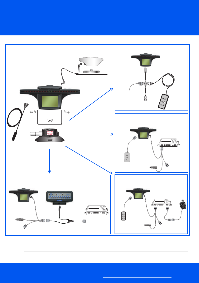
CONNECTING THE SYSTEM
Optional remote control
Standard system
Optional T2™ terrain compensation
technology
®
Optional EZ-Boom™ 2010 automated application
CAUTION — Keep the lightbar dry. Do not spray it with any type of liquid as this may cause it to fail.
C
control system
A
58378R REV 1
DCA 0615
www.EZ-Guide.com
Optional EZ-Steer
steering system
assisted
Page 2
EZ-Guide® Plus Lightbar Guidance System
Quick Reference Card
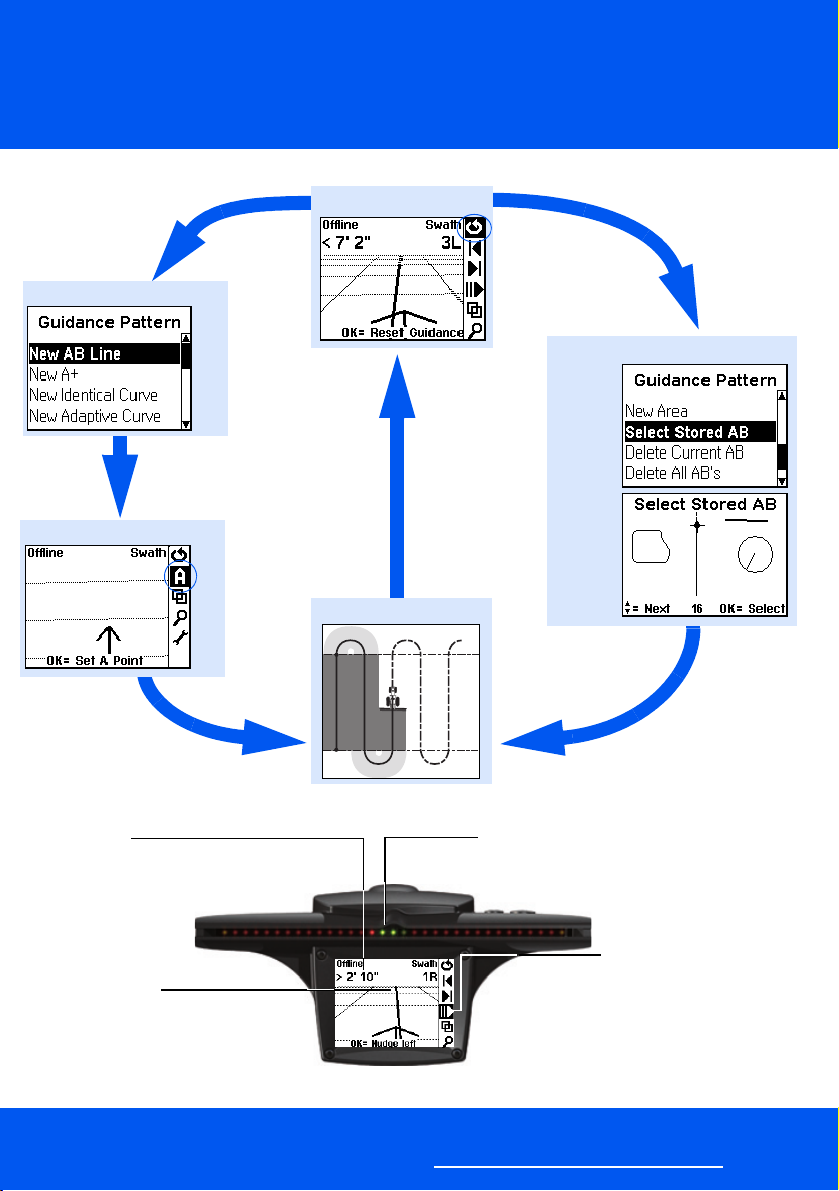
QUICK START: GETTING GUIDANCE
Reset guidance:
Select a guidance pattern:
Load an existing guidance line:
Define a guidance line:
Drive with guidance:
B
DRIVING WITH GUIDANCE
Status text
The status text shows information like how
far offline you are and
the number of the
swath that you are on.
Guidance line
The arrow represents your vehicle.
Steer the vehicle so the arrow moves
along the guidance line.
A
www.EZ-Guide.com
A
LEDs
When the three green LEDs in the center of
the lightbar are illuminated, you
are online.
Pause
Need to pause guidance? Just select
the Pause icon (2) and then press
When you move, a dotted line guides you
back to the paused position. Then select 2
to resume guidance.
o.
Page 3
EZ-Guide® Plus Lightbar Guidance System
Quick Reference Card
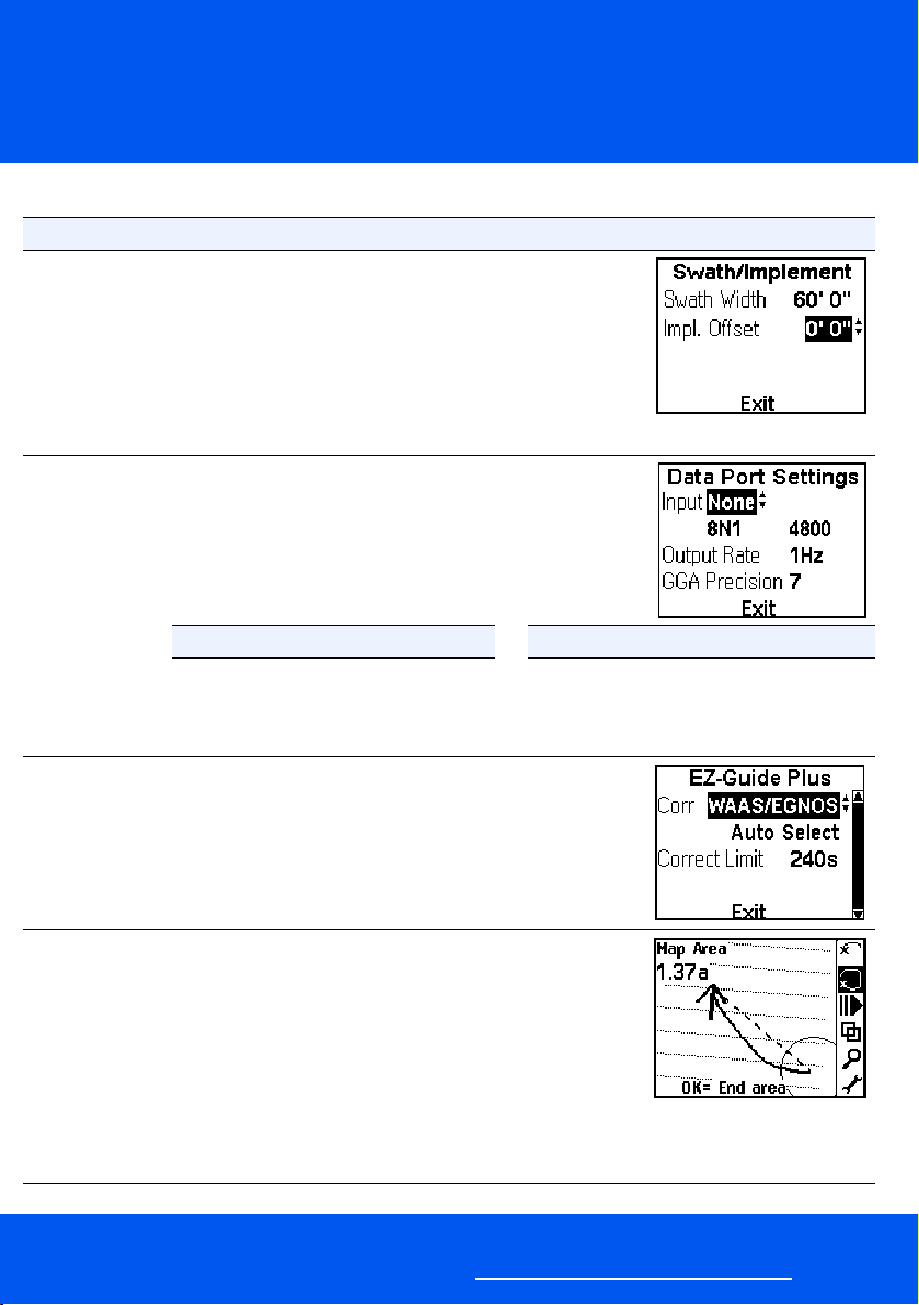
ADVANCED SETUP
To set up ... Complete these steps ...
Implement side
offset
(If the implement
is offset to one
side of the vehicle
centerline)
GPS receiver 1. Select Lightbar / Data Port Settings.
GPS corrections 1. Select GPS / Corrections.
1. Reset guidance and then select a new guidance pattern.
The Swath /Implement screen appears.
2. Select the Impl. Offset field.
3. Press u or D until the correct value is displayed.
4. Press o.
If an implement side offset is configured, the
Note —
guidance arrow will show the center of the implement
instead of the center of the vehicle.
The Data Port Settings screen appears.
2. Press u or D to choose the receiver type from the Input
field.
3. Press o.
Input Select this input for... Input Select this input for...
None Internal GPS receiver Autopilot AgGPS® Autopilot™ system
TSIP Receiver External Ag Leader GPS Corrections RTCM input from a radio
External GPS Third-party GPS receiver Diagnostics Diagnostics with AgRemote
Note — Only correction types supported by your receiver
are available for selection. You cannot configure
corrections for third-party GPS receivers.
2. To edit the WAAS or EGNOS satellites, change Auto Select
to Edit.
Area mapping Use Area Mapping to define an area in the field or to calculate
the size of an area:
1. Select 9 and then press
2. Select New Area and then press o.
3. Select the point on the vehicle that will be used to define
4. Press 8 to begin mapping and then drive around the out-
5. Press D or drive back into the start/finish circle to end.
A
The Guidance Pattern screen appears.
the area and then press o. The main screen appears.
side of the area.
www.EZ-Guide.com
o to reset guidance.
Page 4

EZ-Guide® Plus Lightbar Guidance System
Quick Reference Card
USER INTERFACE
Status text
Configure options from
Lightbar / Status Text.
Action icon bar
To select an icon, press
u or D and then press o.
Tips
Context-sensitive
VIEWS
Action icon Description
9
A
B
8
D
1
3
2
4
5
7
Resets guidance
Sets Point A
Sets Point B
Starts headland
Sets final headland
Nudges guidance line left
Nudges guidance line right
Pauses/Resumes offline guidance and
gets guidance to and from the pause
point, for example, when refilling
Changes views
Zooms screen
Goes to main configuration menu
Select 4 to change between the five views shown below.
Plan map Perspective map Status Offline
Summary
The Summary screen shows area covered,
either when the EZ-Boom 2010 system, the
EZ-Steer system, or an external spray switch is
connected, or everywhere the vehicle drives.
– To configure which type of covered area is
shown, select Lightbar / Display Config and
then adjust the Path Display setting.
– To access the zooming and panning features shown in the table, on the
Summary screen select the
A
5 action icon.
www.EZ-Guide.com
Icon Description
5 End zoom mode
I Move view left
J Move view right
K Move view up
L Move view down
+ Center on vehicle
Zoom in
Zoom out
Page 5
EZ-Guide® Plus Lightbar Guidance System
D
Quick Reference Card
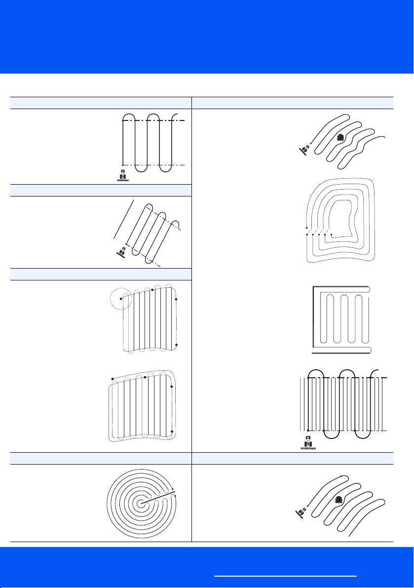
GUIDANCE
AB Line Adaptive curve
Map a straight AB Line for
guidance. You can reset
the B point until you drive
½ swath offline from the
AB Line.
A+
The heading of the AB line
equals the previous AB
heading or the manually
entered heading.
Headland
Straight swaths
automatically fill the
headland boundary. The
AB Line does not need to
be the full length of the
field.
Before you reach the circle
around the start point,
press
D to indicate the
current headland circuit is
the final circuit.
You can do either a single
headland or multiple
headlands.
8
B
A
A
8
D
Auto-detect turn = On
The end of the swath is
automatically detected when
you d o a U -tu rn.
If Auto-detect turn = Off, you
must press B at the end of
every pass.
Spiral
Set Auto-detect turn = Off.
You must press B at the end of
every pass before you start the
turn to mark the end of the
swath.
C-clamp
A
Bold lines indicate where you
must drive swaths without
guidance and thin lines indicate
where you get guidance.
B
Rowfinder
You must press B at the end of
A
every pass to start counting
rows.
B
A
A
B
B
B
B
B
A
B
A
BB
BB
Center-pivot Identical curve
To work from the center of
the field outwards, the
initial pivot must have:
• a radius of at least two
swath widths
This pattern does not
incorporate any deviation
A
around an obstacle.
B
• an arc length of at
least two swath widths
A
www.EZ-Guide.com
B
A
Page 6

EZ-Guide® Plus Lightbar Guidance System
Quick Reference Card
OPTIONAL UPGRADES
Product Details
EZ-Steer assisted steering system The EZ-Steer assisted steering system steers the vehicle down field passes
EZ-Boom 2010 automated
application control system
Remote control
T2 terrain compensation
technology
using GPS guidance from the EZ-Guide Plus lightbar guidance system, a
controller, and a motor mounted to the steering column of the vehicle.
To configure the EZ-Steer system, set the options in the EZ-Steer menu.
For details, refer to the EZ-Steer System Quick Reference Card and Reference
Guide.
The EZ-Boom 2010 automated application control system enables you to
control spray equipment that is either attached to the vehicle or towed.
The EZ-Boom system provides advanced flow control features and automatic
control of up to ten boom sections. You save on chemical costs when you apply
the correct amounts in exactly the right places.
To configure the EZ-Boom system, set the options in the EZ-Boom menu.
For details, refer to the EZ-Boom 2010 Automated Application Control System
Quick Reference Card.
The remote control is an optional accessory that you can purchase separately.
For information, contact your local EZ-Guide Plus system reseller.
The EZ-Guide Plus system firmware version 3.00 and later can use terrain
compensation information from an EZ-Steer controller that includes T2 terrain
compensation technology.
Install the EZ-Steer controller on the floor with the connectors pointing forward,
on the floor with the connectors pointing backward, or on the rear wall with the
connectors pointing to the floor.
To configure terrain compensation, set the options in the Te r ra in C om p. menu.
© 1999-2006. Trimble Navigation Limited. All rights reser ved. EZ-Guide is a registered trademark of Trimble Navigation Limited,
licensed to AgLeader Technology. Trimble, AgGPS, and EZ-Steer are trademarks of Trimble Navigation Limited, registered in the United
States Patent and Trademark Office and in other countries. Autopilot, EZ-Boom, and T2 are trademarks of Trimble Navigation Limited.
Version 4.00, Rev A. (November 2006).
P/N 61050-40-ENG, Rev A
*61050-40-ENG*
A
www.EZ-Guide.com
 Loading...