

Page 1
Ag Leader Technology
Cable – Keypad, Radar, Switch
Ez-Guide Plus / 500 Installation Instructions
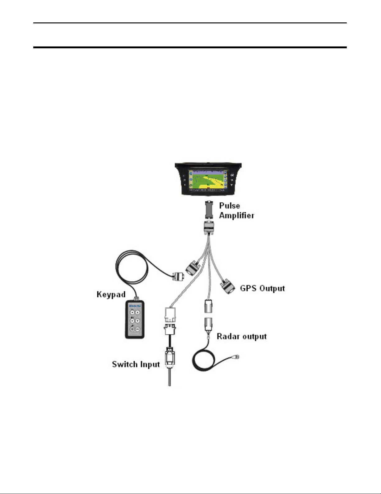
The Keypad Splitter Cable with Implement Switch (pn: 4001225-1) can be used for
multiple connections to the EZ-Guide Plus and EZ-Guide 500 Lightbars. This cable will
connect to the DB9 serial port on the back of the EZ-Guide plus or EZ-Guide 500.
Connections include:
• Keypad input
• Implement Switch input
• GPS signal output
• Radar speed output
Note: The Pulse Amplifier is only needed when connecting radar output to an external
device requiring radar speed. Only Raven, Hiniker and Dickey John monitors are
supported devices.
PN: 2005898 Rev A – June 2007 1
Page 2

Ag Leader Technology
Cable – Keypad, Radar, Switch
Ez-Guide Plus / 500 Installation Instructions
Enabling the implement switch in EZ-Guide Plus
From the run screen, arrow down to the config menu (wrench icon) and press OK.
Arrow down to the “Lightbar” menu and press OK.
Arrow down to “Display Config” and press OK.
Press OK until Path Display is highlighted. Arrow down until “Switch” is displayed
The EZ-Guide Plus will now log coverage area when the implement switch is
triggered.
PN: 2005898 Rev A – June 2007 2
Page 3

Ag Leader Technology
Cable – Keypad, Radar, Switch
Ez-Guide Plus / 500 Installation Instructions
Enabling Implement Switch with EZ-Guide 500
From the run screen, arrow down to the config menu (wrench icon) and press OK.
Arrow down to “System” and press OK.
Arrow down to “Guidance” and press OK.
Arrow down to “Coverage Logging” and press OK.
PN: 2005898 Rev A – June 2007 3
Page 4

Ag Leader Technology
Cable – Keypad, Radar, Switch
Ez-Guide Plus / 500 Installation Instructions
Arrow down to “Switch” and press OK.
The EZ-Guide 500 will now log coverage area when the implement switch is
triggered.
Mounting the Implement Switch
1. Decide on a location for mounting the implement switch.
2. When installing the implement switch, the switch must be mounted so that the
lever is in the off center position when the implement is in the application
position. If this can be done, skip to step 7.
PN: 2005898 Rev A – June 2007 4
Page 5

Ag Leader Technology
Cable – Keypad, Radar, Switch
Ez-Guide Plus / 500 Installation Instructions
3. If the switch cannot be mounted this way, then the wiring in the switch must be
changed. To do this, first open the switch casing.
4. Loosen the screws holding the green and black wires.
5. Remove the green wire from pin-13 and move it to pin-21 and secure it there with
the screw
6. Remove the black wire from pin-14 and move it to pin-22 and secure it there with
the screw. This will allow the implement switch to be centered when the
implement is in the application position.
7. Plug the implement switch into any extension cables that you may need to use.
Route the extension cables to the cab and connect to the splitter cable.
8. Secure the cabling on the implement being careful of pinch points or field
obstructions.
PN: 2005898 Rev A – June 2007 5
 Loading...