

Page 1

Version 4.00
Revision A
January 2009
Page 2

Table of Contents
Introduction...............................................................................................................................................................1
Legal Notices.................................................................................................................................................1
About the EZ−Guide 500 System..................................................................................................................1
Related Information.......................................................................................................................................1
Technical Support..........................................................................................................................................2
About the Lightbar...................................................................................................................................................3
What's in the EZ−Guide 500 Box..................................................................................................................3
Parts of the Lightbar.......................................................................................................................................4
How the Buttons Work..................................................................................................................................5
Optional Accessories......................................................................................................................................7
Upgrades........................................................................................................................................................7
Fuse Information............................................................................................................................................7
Pinout Information.........................................................................................................................................8
Installation.................................................................................................................................................................9
Step 1: Installing the Lightbar Mount............................................................................................................9
Step 2: Installing the Antenna........................................................................................................................9
Step 3. Attaching the Lightbar Cables...........................................................................................................9
Step 4: Turning on the Lightbar...................................................................................................................11
Connecting a Coverage Switch....................................................................................................................11
Getting Started........................................................................................................................................................14
Quick Start Wizard.......................................................................................................................................14
Items on the Main Guidance Screen............................................................................................................15
View Modes.................................................................................................................................................16
Panning.........................................................................................................................................................16
User Modes..................................................................................................................................................17
Changing the User Mode.............................................................................................................................17
Changing the Backlight Brightness..............................................................................................................18
Changing the LED Brightness.....................................................................................................................18
Getting GPS Corrections..............................................................................................................................18
Easy Mode Guidance..............................................................................................................................................20
Introduction to Guidance.............................................................................................................................20
Following Guidance.....................................................................................................................................21
Guidance Patterns........................................................................................................................................22
Getting Guidance.........................................................................................................................................33
Coverage Logging........................................................................................................................................36
Creating straight sections on Headland or Curve swaths.............................................................................36
Pause / Resume Icon....................................................................................................................................36
Advanced Mode Guidance.....................................................................................................................................38
Resetting Guidance......................................................................................................................................38
Creating a New Field or Line.......................................................................................................................38
Adding an AB Line......................................................................................................................................42
Implement Setup..........................................................................................................................................44
Selecting (Loading) an AB Line..................................................................................................................45
i
Page 3

Table of Contents
Advanced Mode Guidance
Selecting (Loading) a Field..........................................................................................................................47
Advanced Mode Additional Information..............................................................................................................52
Views...........................................................................................................................................................52
Night Mode..................................................................................................................................................52
Nudge...........................................................................................................................................................53
Configuring the Lightbar.............................................................................................................................55
Driving on Large Fields...............................................................................................................................57
Driving Tight Turns.....................................................................................................................................57
Adding a Time Delay to Coverage Logging................................................................................................58
Configuring Coverage Logging...................................................................................................................58
Setting the Look Ahead Value.....................................................................................................................59
Enabling Speed Pulse Output (Radar).........................................................................................................59
Recording events..........................................................................................................................................60
Restoring the Default Lightbar Settings.......................................................................................................60
Advanced Mode GPS Corrections.........................................................................................................................61
Configuring the GPS Corrections................................................................................................................61
Configuring the GPS Limits........................................................................................................................65
Configuring NMEA message output............................................................................................................66
External Receiver Support...........................................................................................................................68
Advanced Mode Data Management......................................................................................................................71
USB Drive Compatibility.............................................................................................................................71
Getting Data from the USB Drive................................................................................................................72
Importing Data from the AgGPS FieldManager Display............................................................................73
Sending Data to the USB Drive...................................................................................................................73
Clearing Storage Space................................................................................................................................74
Deleting coverage logging...........................................................................................................................75
Exporting Diagnostic Logs..........................................................................................................................75
Field Name Structure...................................................................................................................................75
Default Field Names....................................................................................................................................76
Naming a Field.............................................................................................................................................76
System Configuration Files..........................................................................................................................77
Summary Report..........................................................................................................................................78
Viewing/Editing Data with Office Software................................................................................................79
Upgrading Firmware....................................................................................................................................80
Upgrading Lightbar Functionality...............................................................................................................82
Mapping...................................................................................................................................................................83
Introduction to Mapping..............................................................................................................................83
Mapping Features.........................................................................................................................................83
Recording Position.......................................................................................................................................85
Warning Zones.............................................................................................................................................86
Displaying Feature Information...................................................................................................................87
Deleting Features.........................................................................................................................................88
ii
Page 4

Table of Contents
Obtaining Information from the Lightbar...........................................................................................................90
The About the EZ−Guide Screen.................................................................................................................90
Information Tabs..........................................................................................................................................90
Status Screens..............................................................................................................................................90
Warning Messages.......................................................................................................................................91
Troubleshooting...........................................................................................................................................91
EZ−Boom 2010 System...........................................................................................................................................93
EZ−Boom Features......................................................................................................................................93
Refilling the Tank........................................................................................................................................94
EZ−Boom Flow Calibration.........................................................................................................................95
Manual Override..........................................................................................................................................95
Swath Control Menu....................................................................................................................................96
Spraying Pivots............................................................................................................................................96
Prescriptions............................................................................................................................................................97
Introduction to Prescriptions........................................................................................................................97
Importing Prescriptions................................................................................................................................97
Loading a Prescription.................................................................................................................................98
iii
Page 5

Introduction
Legal Notices
(c) 2007−2009, Trimble Navigation Limited. All rights reserved.
Trimble, AgGPS, EZ−Guide, and EZ−Steer are trademarks of Trimble Navigation Limited, registered in the
United States and in other countries. Autopilot, Autoseed, FreeForm, OnPath, and SiteNet are trademarks of
Trimble Navigation Limited.
All other trademarks are the property of their respective owners.
This product is covered by the following patents: 5,311,149, 5,369,589, 5,987,383, 6,252,863, 5,402,450,
5,493,588, and 6,463,374. Other patents pending.
For Limited Warranty information, refer to the EZ−Guide 500 Lightbar Guidance System Release Notes.
About the EZ−Guide 500 System
The EZ−Guide 500 system is a GPS guidance system for agricultural vehicles. It helps you drive the vehicle more
efficiently by reducing skips and overlaps in the field.
The system includes the following features:
a color LCD screen•
a lightbar with 31 LEDs•
an internal GPS receiver•
multiple field patterns for different field layouts•
Related Information
Sources of related information include the following:
1
Page 6

Help − the lightbar has built−in, context−sensitive help that lets you quickly find the information you
•
need.
Quick reference card − the quick reference card describes the most common features of the lightbar.•
Technical Support
If you have a problem and cannot find the information you need in the product documentation, contact your local
reseller. Alternatively, go to the EZ−Guide website at http://www.ez−guide.com/.
2
Page 7

About the Lightbar
What's in the EZ−Guide 500 Box
The standard components of the EZ−Guide 500 system are shown below.
ITEM DESCRIPTION
1 EZ−Guide 500 documentation CD
2 Quick Reference Card
3 RAM mount
4 Antenna mount plate
5 Power cable (P/N 62817)
6 Power connector cable (P/N 62818)
7 EZ−Guide 500 lightbar
8 Antenna cable (P/N 50449)
9 Antenna
When you unpack the box, inspect all contents for visible damage, such as scratches or dents. If any components
appear damaged, notify the shipping carrier. Keep the shipping and packaging material for the carrier's inspection.
3
Page 8
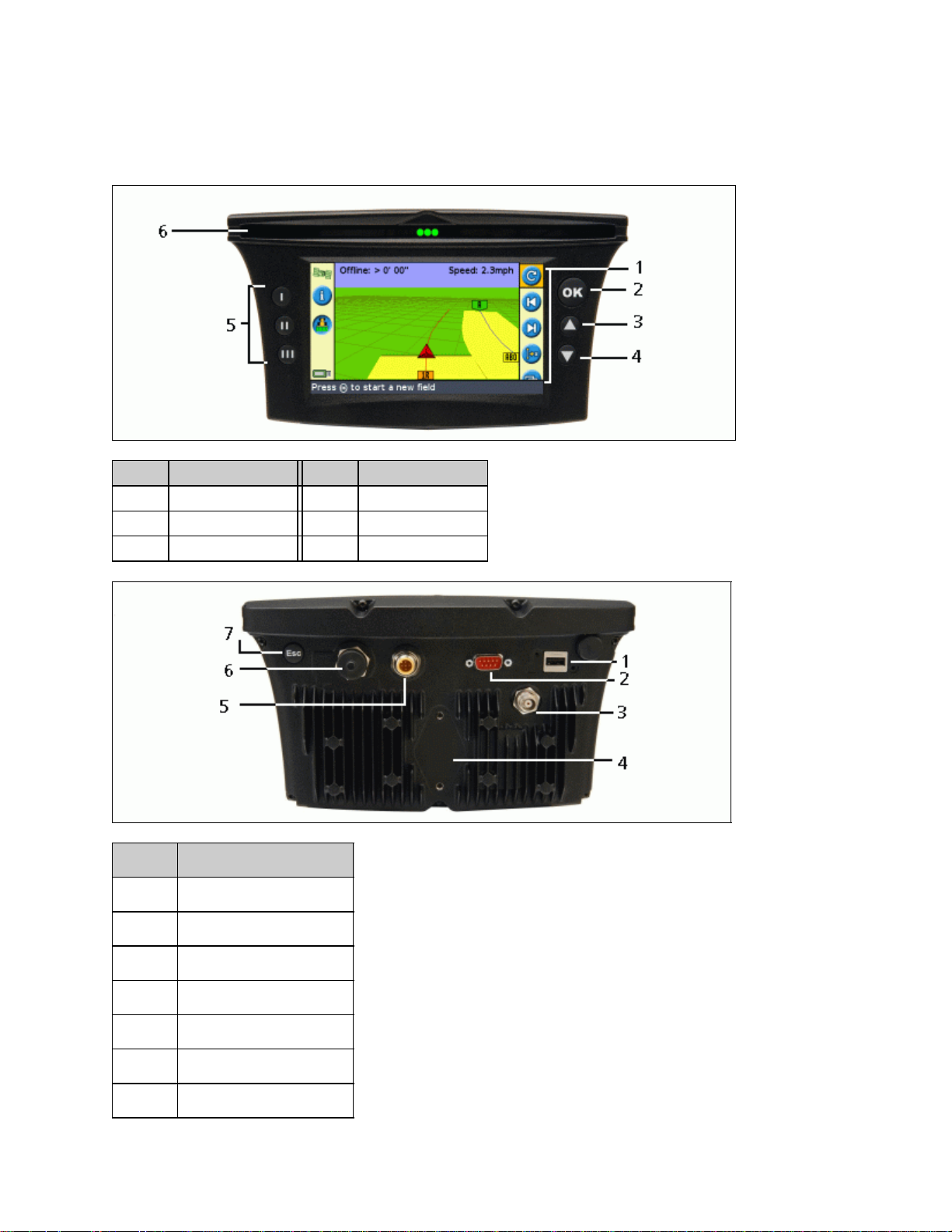
Parts of the Lightbar
The following figures show the front and back of the lightbar.
ITEM DESCRIPTION ITEM DESCRIPTION
1 Action icons 4 Down button
2 OK button 5 Function buttons
3 Up button 6 LEDs
ITEM DESCRIPTION
1 USB port
2 Serial (COM) port
3 Antenna port
4 RAM mount fixture
5 Power socket
6 Extension (AUX) port
7 Escape button
4
Page 9

How the Buttons Work
On the front of the lightbar, there are six buttons. The buttons on the left and right sides of the lightbar work in
different ways.
Action buttons (on the right of the screen)
On the main guidance screen:
Press or to scroll through the action icons.•
Press to select the highlighted icon.•
The following icons may appear to the right of the guidance screen:
ICON DESCRIPTION ICON DESCRIPTION
Reset guidance Nudge left
Set Point A Nudge right
Set Point B Pause guidance
Start headland Resume guidance
Complete headland Change zoom scale
Pause swath recording
Resume swath recording Change view mode
Currently recording FreeForm curve (press to stop)
Not currently recording FreeForm curve (press to start) Shift AB Line
Display point, line and area mapping icons
Note: Action icons appear only when they are appropriate. They are not all visible at all times.
The following action icons may appear on the right of a configuration screen:
ICON DESCRIPTION ICON DESCRIPTION
Go to main
Configuration menu
Next FreeForm
segment
Display panning
icons
Increase value / up to next option Proceed to next screen
Decrease value / down to next option Accept settings
5
Page 10

In setup screens, the icons match the buttons beside them.
Function buttons (on the left)
Beside each function button, there is an icon. When you press the function button, you select the feature that is
shown on the icon.
ITEM DESCRIPTION
1 Coverage logging icon
2 Middle function button
The following function icons may appear beside the buttons on the left of the screen:
ICON DESCRIPTION ICON DESCRIPTION
Display information tab window Cancel changes
Turn on coverage logging Go up one menu level
Turn off coverage logging Return to guidance screen
Zoom in Move back one screen
Zoom out Display Help
Escape (ESC) button
Press the Escape button on the back of the lightbar to cancel out of screens and to move up menu levels. See Back
of the Lightbar.
Getting help
6
Page 11

The EZ−Guide 500 lightbar has built−in help that explains how to use the current screen. To access the help, press
the function button:
Optional Accessories
ITEM DESCRIPTION
There are two antenna options for the EZ−Guide 500 lightbar:
− Ag15 antenna for autonomous positions and free WAAS and EGNOS DGPS corrections
Antenna
− Z+ high−accuracy antenna for OmniSTAR XP/HP or RTK corrections
Caution: Do not use the patch antenna from the EZ−Guide 250 lightbar with the EZ−Guide 500
lightbar. The patch antenna uses a different voltage to other EZ−Guide antennas and the
EZ−Guide 500 lightbar will damage it.
Remote
keypad
With the optional remote keypad installed, you can control the lightbar without having to reach to
it. The six buttons on the keypad mirror the six buttons on the front of the lightbar.
Upgrades
The EZ−Guide 500 lightbar guidance system can be connected to:
the EZ−Steer® assisted steering system•
the AgGPS® Autopilot(TM) automated steering system•
the EZ−Boom(TM) 2010 automated application control system (when the lightbar has firmware version
•
2.00 or higher)
a serial variable rate controller•
Fuse Information
The EZ−Guide 500 lightbar has two fuses:
FUSE LOCATION DESCRIPTION
In cigaretter lighter connector of power connector cable (P/N 62818) 30 A glass cartridge fuse.
In fuse holder on power cable (P/N 62817) 10 A spade fuse.
7
Page 12

Note: Both fuses can be replaced by the user.
Replacing the 30 A fuse
Locate the cigarette lighter plug holder on the end of the cable.1.
Unscrew the end cap where the spring−loaded pin protrudes. Be careful not to lose the pin after removing
2.
the end cap.
Remove the old fuse.3.
Insert the new fuse and then screw the end cap back onto the plug.4.
Replacing the 10 A fuse
Open the cap on the fuse holder.1.
Pull out the old fuse.2.
Insert the new fuse.3.
Close the cap on the fuse holder.4.
Pinout Information
The DE−9M (serial port) on the EZ−Guide 500 lightbar has the following pinout information:
ITEM DESCRIPTION
1 Event out to keypad (to signal audio alarm)
2 RS−232 Rx
3 RS−232 TX
4 External switch input
5 Data ground
6 Keypad data input
7 Keypad clock
8 External output (radar pulse)
9 Keypad power
8
Page 13

Installation
Step 1: Installing the Lightbar Mount
Select a place in the cab for the lightbar. There must be a mounting bar available for attaching the RAM
1.
mount.
Sit in the driver's seat and hold the lightbar in the place that you selected, make sure that you can access it
2.
comfortably from there.
Step 2: Installing the Antenna
Note: To minimize any interference to the GPS signal, make sure that the GPS antenna is at least 1 m (3 ft) from
any other antenna (including a radio antenna). You may experience interference if you operate the vehicle within
100 m (300 ft) of any power line, radar dish, or cell phone tower.
Installing the Z+ high accuracy antenna
Find the mounting location for the antenna at the front of the vehicle roof.
Screw the antenna mag mount onto the antenna.1.
On the mounting plate, remove the protective covers from the adhesive strips.2.
Attach the mounting plate to the vehicle roof with the adhesive strips. Ensure that the mounting plate is
3.
centered along the vehicle roof.
Connect the antenna cable to the antenna.4.
Place the mag mount (with antenna) directly onto the mounting plate of the vehicle.5.
Route the other end of the antenna cable into the cab.6.
Installing the Ag 15 antenna
Find the mounting location for the antenna at the front of the vehicle roof, centered from left to right.
On the mounting plate, remove the protective covers from the adhesive strips.1.
Attach the mounting plate to the vehicle roof with the adhesive strips. Ensure that the mounting plate is
2.
centered along the vehicle roof.
Connect the antenna cable to the antenna.3.
Place the antenna directly on the mounting plate. The three magnets embedded in the bottom of the
4.
antenna will hold it in place.
Route the other end of the antenna cable into the cab.5.
Step 3. Attaching the Lightbar Cables
The lightbar with the basic antenna and power configuration:
9
Page 14

ITEM DESCRIPTION
1 Antenna (P/N 60600−01 for DGPS or P/N 57200−00 for OmniSTAR/RTK)
2 Antenna cable (P/N 50449)
3 Remote keypad (optional − P/N 66030−00)
4 Power cable (P/N 60198 or P/N 62817)
5 Power connector cable (P/N 62818)
6 To power (cigarette lighter)
7 EZ−Guide 500 lightbar (reverse)
Connect the power cable to the power port on the back of the lightbar.1.
Note: Ensure that the power cable points straight into the back of the lightbar − not at an angle.
Connect the antenna cable to the antenna port.2.
Tighten the cable connector until it is fully secure.3.
Connect the other end of the power cable to the vehicle cigarette lighter. The lightbar turns on.4.
Caution: Do not disconnect or connect any cables or connect the EZ−Steer 500 system while the lightbar is
running. To connect or disconnect cables, first turn off the system.
10
Page 15

Step 4: Turning on the Lightbar
To turn on the lightbar, plug the power cable into the cigarette lighter:
If the cigarette lighter is wired through the vehicle ignition, insert the key and turn on the vehicle ignition.
•
The lightbar receives power and turns on.
If the cigarette lighter is not wired through the vehicle ignition, the lightbar receives power whenever the
•
cable is plugged in. The lightbar draws some power even when it is turned off, so disconnect the lightbar
from the power source if the vehicle will be unused for an extended time to avoid draining the vehicle
battery.
Turning off the lightbar
To turn off the lightbar, unplug the power cable from the cigarette lighter.
Connecting a Coverage Switch
Connect an interface cable to the lightbar.1.
Attach the female WeatherPack connector (supplied) to the wires of a switch (not supplied).2.
Configure the switch on the lightbar.3.
Caution: Ensure that you do not supply either wire with power. If necessary, use a relay to isolate the lightbar
from the power source.
Connecting an interface cable to the lightbar
The coverage switch requires one of the following external interface cables with a 3−pin WeatherPack connector:
External interface cable (P/N 52033)•
External interface cable (right angle connector) (P/N 62749)•
Attaching a female WeatherPack connector to the switch wires
Strip about 1 cm (0.4 inches) of insulation off the switch wires.1.
Thread each switch wire through a cable seal:2.
Crimp terminal connectors to the ends of the wires with an appropriately−sized crimp tool or pliers and
3.
then solder the terminal connectors to the wire to ensure a secure connection:
11
Page 16

Insert the wires with terminal connectors and the cable seals into the appropriate holes on the female
4.
WeatherPack connector:
Ground wire − Connector hole B♦
Switch wire − Connector hole C♦
Caution: Ensure that you do not supply either wire with power. If necessary, use a relay to isolate the
lightbar from the power source.
Plug the female connector into the male connector on the interface cable:5.
Enabling the switch on the lightbar
From the main guidance screen:
Press until you have selected the icon.1.
Press . The Configuration screen appears.2.
Make sure that the User Mode field is set to Advanced.3.
12
Page 17

Select System / Guidance. The Guidance screen appears:4.
Select Coverage Logging and then press . The Coverage Logging screen appears:5.
Press until you have selected Switch and then press .6.
In the Coverage Logging Input screen, select one of the two options:7.
ITEM DESCRIPTION
Active Low
Active High
Note: If necessary, set the user mode back to Easy.
When the switch is closed, the two pins should be crossed and the coverage will be recorded.
When the switch is open, the two pins will not be in contact and the coverage will not be recorded.
When the switch is open, the two pins will not be in contact and the coverage will be recorded.
When the switch is closed, the two pins should be crossed and the coverage will not be recorded.
13
Page 18

Getting Started
Quick Start Wizard
When you turn on the lightbar the Welcome to EZ−Guide 500 screen appears automatically:
Press . The Quick Start Wizard appears.
The wizard has several setup screens that enable you to configure important settings before you begin driving.
During the Quick Start Wizard, you can press the function button to exit at any point. The system uses any
settings you have entered; for any settings that you have not yet entered, the system uses the settings from last
time.
The first time that you run the lightbar, complete the whole wizard.
ITEM DESCRIPTION
1 Quit the wizard
2 Built−in help
3 Skip the wizard and begin driving
To adjust a setting:
14
Page 19

Press or to select the correct value.1.
Press to enter the selection and proceed.2.
You can select whether or not the Quick Start Wizard appears next time you turn on the lightbar. If you choose to
hide the wizard at startup, the lightbar skips the wizard and starts on the main guidance screen.
To alter these settings after startup, run the Quick Start Wizard from Configuration / Quick Start Wizard.
Once you complete the Quick Start Wizard, the main guidance screen appears.
Items on the Main Guidance Screen
ITEM NAME DESCRIPTION
There are two status text items on the main guidance screen. The item on
1 Status text
2 Action icons How the Buttons Work
3
4 USB status icon
5 Function icons How the Buttons Work
6 GPS quality icon
Tips / Message
panel
the left shows the distance that the vehicle is from the guidance line. The
item on the right shows the current vehicle speed.
The Tip / message panel explains the icon functions and shows driving
tips.
Show the status of the USB drive:
Green − the drive is installed and ready
Orange − the drive is installed, but still loading
Red − the drive has been disabled due to an error
Shows the quality of the GPS signal:
Green − the signal is within the appropriate bounds
Yellow − there is a signal, but it is outside the lightbar's quality tolerance
settings
Red − there is no signal
15
Page 20

View Modes
There are two views when you are driving in the field:
PERSPECTIVE MAP VIEW PLAN MAP VIEW
A 3D view of the field A bird's eye view of the field
By default, the view switches from plan view to perspective view when you enter the field.
You can change the view mode in Advanced mode.
Panning
On the EZ−Guide 500 lightbar, you can pan (move) the screen around to better see parts of the field, for example
to check for skips in application coverage or the location of point, line and area features.
Note: The vehicle must be stationary when entering panning mode.
To enter panning mode, select the icon and press . A new set of panning icons appears on the right of the
screen.
Note: The map is always displayed North−Up in panning mode.
To move the screen, select one of the arrow icons on the right of the screen and press . The screen moves in
the direction of the arrow. Repeat with the same arrow or change arrows as many times as necessary.
To zoom in or out on the screen, use the buttons on the left of the screen.
16
Page 21

ITEM DESCRIPTION
Zooms to the extents of the field. This includes the field boundary (if present), coverage logging
and any mapped features.
Zooms in
Zooms out
Note: To ensure all coverage logging is shown, turn off coverage logging before entering panning mode.
Otherwise, the coverage polygon currently being recorded will not be shown in panning mode.
User Modes
The EZ−Guide 500 lightbar guidance system has two user modes:
MODE DESCRIPTION
Limited to accessing the most simple features
Easy
Advanced The user can access all of the settings.
Fewer action icons are available
Simplified driver options (for example, creating a guidance line is easier)
Use Easy mode if you want to select a swath pattern and quickly begin driving.
Changing the User Mode
To change between Easy mode and Advanced mode:
Select Configuration / User Mode. The User Mode screen appears:1.
Select Advanced or Easy and then press . The main guidance screen reappears, with the lightbar in
2.
the selected mode.
17
Page 22

Changing the Backlight Brightness
To change the strength of the screen backlight, select Configuration / Backlight.
Changing the LED Brightness
To adjust the brightness of the LEDs on the lightbar, select Configuration / LED Brightness.
In bright sunlight, increase the brightness to make the LEDs more obvious.•
In darker conditions, for example driving at dusk, you can lower the brightness settings so the LEDs are
•
less intense.
Getting GPS Corrections
By default, the EZ−Guide 500 lightbar is configured to receive the following free corrections:
REGION CORRECTION
North America WAAS
Europe EGNOS
These corrections provide 15 cm−20 cm (6 in−8 in) pass−to−pass accuracy.
To change the GPS corrections (for example, to configure RTK or OmniSTAR VBS/HP/XP), select
Configuration / GPS Setup / GPS Correction Source.
External Receiver Support
The EZ−Guide 500 lightbar can recieve GPS positions from TSIP−compatible recievers. This enables you to use
any of the correction types available on your receiver, including OmniSTAR, Beacon, and RTK.
The following TSIP−compatible recievers are supported by the EZ−Guide 500 lighbar:
Trimble Case IH Ag Leader New Holland
AgGPS 252 AFS 252 GPS 5100 NH 252
AgGPS 332 − − −
To enable TSIP messages as the correction source:
Connect the receiver to the lightbar and then turn them on.1.
Select Configuration / GPS Setup.2.
Change the GPS Correction Source option to Ext. TSIP.3.
Select Continue and press . The Connecting to External Receiver screen appears. The lightbar
4.
connects to the TSIP receiver. The message Connection Established appears.
Press . The External DGPS Source screen appears, showing the available corrections on the reciever.5.
18
Page 23

Select the appropriate correction source and then press . The wizard for that correction type appears.6.
Note: When the lightbar is receiving GPS positions from the TSIP−compatible receiver, additional entries appear
on the Info tab.
19
Page 24

Easy Mode Guidance
Introduction to Guidance
The EZ−Guide 500 lightbar uses onscreen lines, either straight or curved, to guide you. These are called the
guidance lines. The most simple form of guidance line is a straight AB Line. To create an AB Line, you define a
start point (the A point) and an end point (the B point). Once you define the A and B points, a straight line is
drawn between them. This is your master line.
When you define the first guidance line, the lightbar copies it to create additional guidance lines.
Distance between guidance lines
When you begin to define the line, you specify the width of the implement attached to the vehicle. This width is
used to calculate the distance between the guidance lines. If you do not want the guidance lines to be exactly one
implement width apart, you can set an overlap or skip.
Headlands
You can record a headland boundary and get guidance to it, or you can work without a headland.
Onscreen appearance
When the main guidance screen shows the perspective view, the lines are tagged with flags that describe them.
ITEM DESCRIPTION
20
Page 25

The master line that you created, and that the swaths are based on.
The A (start) and B (end) point on the master line.
The first swath to the left of the master line. (The direction "left" is relative to the direction the
master line was drawn, not the vehicle's current position).
The current swath and tag are orange.
Note: On a Pivot pattern, the swaths are numbered out from the center, not from the initial
swath.
The second line to the left of the master line.
Following Guidance
The lightbar displays guidance in two places:
On the LEDs•
On the screen•
Guidance on the LEDs
The term LED refers to the row of 31 Light Emitting Diodes (LEDs) that are located above the screen. The LEDs
that are lit up show the position of your vehicle relative to your intended guidance line. As your vehicle position
changes in relation to the guidance line, the lit LEDs move left or right. Use the lightbar to obtain accurate
guidance, if an implement offset or implement draft is set, or for fine guidance on straight swaths.
VEHICLE POSITION LIGHTBAR APPEARANCE
Vehicle is directly on the guidance
line
The three center LEDs (green) show that the vehicle is online.
Vehicle is off the guidance line
The lit LEDs have moved right. This shows that the vehicle is offline to
the left.
Note: This assumes that the LED Mode is set to Chase (the default). If
the LED Mode is set to Pull, the LEDs move left when the vehicle is
offline to the left.
Guidance on the screen
The lightbar screen shows the position of your vehicle in the field, the guidance line, and the offline distance, so
you can tell how much you need to correct your position.
21
Page 26

ITEM DESCRIPTION
1 Offline distance
2 Guidance line
3 Vehicle position
Guidance Patterns
The EZ−Guide 500 lightbar has seven guidance patterns so you can create guidance to suit your field layout.
Straight AB
A Straight AB is the most simple form of line. Use a straight AB Line when you do not need to define headlands
and you want to drive the field in parallel straight lines.
To create a straight AB Line, define a start point (A) and an end point (B). The Straight AB Line then appears as a
straight line between the two points.
PATTERN EXAMPLE
Note: When the vehicle is on a guidance line, the line extends 1 km (0.6 miles) before Point A and 1 km beyond
Point B. This makes it easier to see where the next swath is, and to get online after the turn.
Mapping an AB Line
22
Page 27

Drive to the start point of the master line.1.
Set the A point:2.
Press or until you have selected the icon.a.
Press . The A point is set.b.
Drive to the other end of the line.3.
Ensure that the icon is selected and then press . The master AB Line appears.4.
Turn left or right for the next swath. As you move toward the next swath, it appears on the screen and
5.
turns orange to show that it is selected.
A+ Line
An A+ line is also a straight line. It is defined by a single point on the line (the A point) and the heading of the
line.
PATTERN EXAMPLE
When you choose to create an A+ line, you enter the heading.
The default heading is the same as the previous AB Line. This pattern is useful for when you need guidance
exactly parallel to the last AB Line, for example when:
driving adjacent fields•
mapping the AB Line on a road down the side of the field•
skipping an access road in a field•
The A+ line extends 1 km (0.6 miles) before and after the A point.
23
Page 28

Mapping an A+ line
Drive to the start point of the master line.1.
Set the A point:2.
Press or until you have selected the icon.a.
Press . The A point is set. Because you have already set the line heading, your master AB
b.
Line appears on the screen.
Follow the AB Line for guidance down the first swath.3.
Turn left or right for the next swath. As you move toward the next swath, it appears on the screen and
4.
turns orange to show that it is selected.
Identical Curve
The identical curve pattern records your exact route between the A and B points, instead of a straight line.
All of the guidance lines will match the master curve, regardless of where the vehicle has driven. Use the curve
pattern when you want to work the field with gentle curves.
PATTERN EXAMPLE
Mapping an identical curve
Drive to the start point of the curve.1.
Set the A point:2.
Press or until you have selected the icon.a.
Press . The A point is set.b.
Drive the initial curve.3.
Ensure that the icon is selected and then press . The master line appears on the screen.4.
Turn left or right for the next swath. As you move toward the next swath, it appears on the screen and
5.
turns orange to show that it is selected.
Adaptive Curve
The adaptive curve pattern is similar to the identical curve pattern. It provides guidance along a curve. However,
the adaptive curve pattern updates guidance after each swath to take into account any deviations you made.
It continually records your path and provides guidance that matches the last path you drove.
24
Page 29

PATTERN EXAMPLE
There are two ways to define adaptive curves:
Set the A and B points•
Set the A point and perform a U−turn onto the next swath (which is automatically detected)•
The method that you use depends on the Auto U−Turn detection setting.
Changing the Auto U−Turn detection setting
Note: To change the Auto U−turn detection, the lightbar must be in Advanced mode.
Select Configuration / System / Guidance. The Guidance screen appears.1.
Adjust the Auto U−Turn detection setting.2.
Mapping an adaptive curve
There are two ways to use the adaptive curve pattern:
Automatically: Set the Auto U−turn detection option to On and then perform a U−turn to generate each
•
new swath.
Manually: Set the Auto U−turn detection option to Off and then set the B point at the end of each swath to
•
generate the next swath.
Adaptive curves with automatic turn detection
Drive to the start point of the curve.1.
25
Page 30

Set the A point:2.
Press or until you have selected the icon.a.
Press . The A point is set.b.
Drive the initial curve.3.
At the end of the first curve, perform a U−turn. The system detects the turn and generates the next swath.4.
Adaptive curves with manually defined swaths
Drive to the start point of the curve.1.
Set the A point:2.
Press or until you have selected the icon.a.
Press . The A point is set.b.
Drive the initial curve.3.
At the end of the first curve, select the icon to set the B point. The system generates the next swath.4.
Continue to drive the swaths, setting the B point at the end of each one.5.
Using the adaptive curve pattern to do rowfinding
In Advanced mode, select Configuration / System / Guidance and then set the Auto U−Turn detection
1.
option to Off.
Reset guidance:2.
Enter the width of the implement.a.
Create a guidance line based on the adaptive curve pattern.b.
Set the B point at the end of each row.3.
Turn the vehicle toward the next swath. When the vehicle is halfway through the turn, guidance along the
4.
next swath appears.
Curve smoothing
By default, curves are smoothed by the EZ−Guide 500 for improved guidance and autosteering. You can disable
curve smoothing on tight turns (curves that have a radius of less than 3m (10ft).
CAUTION: If you disable curve smoothing, the EZ−Steer 500 system or the AgGPS Autopilot system may not
be able to autosteer around the tighter turns. Be careful when you disable curve smoothing.
To disable curve smoothing:
Set the lightbar to Advanced mode.1.
Select Configuration / System / Guidance / Minimum Turn Radius Mode.2.
Select Disabled.3.
Pivot
Use the Pivot pattern on fields that are irrigated using a center−pivot. With this pattern, you can drive concentric
circles around the center−pivot.
PATTERN EXAMPLE
26
Page 31

Mapping a pivot
Note: Always set the master line near the outer edge of the field.
Drive to the start point of the pivot.1.
Position one wheel of the vehicle in a pivot wheel rut, with the rear of the vehicle to the pivot arm. If the
2.
field is not a full circle pivot, face the rear of the vehicle to the edge of the field.
Set the A point:3.
Press or until you have selected the icon.a.
Press . The A point is set.b.
Drive around the field. Keep the vehicle wheel in the rut. The lightbar does not yet provide guidance.4.
When you have driven at least 1/4 of the pivot circumference, map Point B. The lightbar generates
5.
guidance swaths.
Turn left or right for the next swath. As you move toward the next swath, it appears on the screen and
6.
turns orange to show that it is selected.
Steer the vehicle so that the lit LEDs are centered on the lightbar as you drive forward along the swath.7.
Headland
The Headland pattern enables you to define the boundary ( "Headland" ) of the pattern, as well as the guidance
lines contained within it. Use the Headland pattern to give you room to turn. You start to define the headland, you
define the internal guidance line as you drive around the headland, and then you complete the headland.
PATTERN EXAMPLE
27
Page 32

You can change two settings for the Headland pattern:
The number of circuits•
The internal pattern (in Advanced mode only)•
Number of circuits
When you create a headland, you need to specify the total number of circuits (including the master
headland). This defines how wide the headland is.
Note: No matter how many circuits you are creating, you only define the outside headland. The inner
headlands circuits are copied from that original circuit.
Internal pattern
The internal pattern is the pattern of the guidance lines inside the headland. In Easy mode, the internal
pattern is automatically an AB Line. In Advanced mode, there is a choice of two internal pattern types:
ITEM DESCRIPTION
Straight AB Creates standard parallel swaths inside a headland
A+ Creates parallel swaths at a pre−defined heading
Ending the headland
Note: You need to define the master line for the internal pattern before you complete the headland.
To finish defining the headland, do one of the following:
28
Page 33

Drive the headland until you return to the start point. When you enter the circle around the start point, the
•
headland completes automatically.
Drive part of the headland and then select . The headland completes with a straight line from the
•
vehicle position back to the start point.
Reselecting the headland
When you use the headland pattern, you can see either the headland or the internal pattern, not both at once.
Headland pattern visible Internal pattern visible
When you are driving the internal pattern and want to see the headland guidance again, do one of the following:
Drive into the headland before the first internal swath or after the final internal swath. The headland
•
appears automatically.
(Advanced mode only) Drive into the headland and then use the Select AB Line option to reload the
•
headland.
Mapping a headland
If the internal pattern is an A+ line, the line appears.•
Drive to the start point of the headland.1.
Select the icon and then press to set the start point of the headland.2.
Begin to drive the circuit of the headland.3.
Note: To ensure straight sides on the headland, you can use the pause feature. See Straight sections on
curves.
While you are driving the circuit, select the icon to set the A point of your guidance line.4.
If the internal pattern is an A+ line, the line is set.♦
If the internal pattern is an AB Line, continue to drive around the headland. When you reach the
♦
other end of the internal guidance line, select the icon to set the B point.
When you have defined the internal pattern guidance line, the start−point circle appears around the start
point of the headland.
Note: If you return to the start of the headland before you define a guidance line, the headland will not
complete.
29
Page 34

To complete the headland, do one of the following:5.
Drive around the rest of the headland and then drive back into the start−point circle. When you
♦
drive into the start−point circle, the headland is defined.
Select the icon and then press . The headland completes with a straight line from the
♦
vehicle position to the start point.
The headland guidance line appears.
When the vehicle moves out of the headland and into the interior of the pattern, the interior is populated
with guidance lines (straight AB or A+, depending on which internal pattern you selected).
FreeForm
The FreeForm(TM) guidance pattern is an advanced pattern that enables you to create multiple lines of different
types in a single field to obtain guidance in fields of any shape. You need to record each line that you drive, to
generate the next guidance line. You can create:
Curved line segments•
Straight line segments in the form of straight AB Lines•
With this combination, the FreeForm pattern can be useful for creating non−circular spirals or multiple curved
guidance lines for irregular−shaped fields.
PATTERN EXAMPLE
The FreeForm Recording option
When you are driving a curve, you need to record your path so the lightbar can create your next guidance line.
There are several different options that control when the lightbar records your path:
ITEM DESCRIPTION
Manual
Coverage
The icon enables you to manually start recording a FreeForm curve and the icon
enables you to manually end recording.
A FreeForm curve is recorded whenever coverage logging is enabled.
If the EZ−Boom 2010 system is connected, a FreeForm curve is recorded whenever the
EZ−Boom master switch is on.
To adjust the FreeForm Recording option:
30
Page 35

Set the lightbar to Advanced mode.1.
Select Configuration / System / Guidance / FreeForm Recording.2.
Select the appropriate setting.3.
Recording a FreeForm curve
It is necessary to record each curved pass, so the lightbar can create the next guidance line.
Set the FreeForm Recording option.1.
Drive to the start point of the FreeForm curve.2.
Begin logging your path:3.
Select the icon and then press .♦
If the FreeForm Recording mode is set to Coverage, select the icon.♦
When your current path is being recorded, the FreeForm recording icon appears. To get
guidance on your next pass, the icon must be green.
Drive the curve. To record straight sections in the FreeForm curves, you can use the pause feature. See
4.
Straight sections on curves.
To complete the FreeForm curve, do one of the following:5.
Perform a tight U−turn.♦
Select the icon and then press .♦
If the FreeForm Recording mode is set to Coverage, select the icon.♦
Note: When the FreeForm Recording mode is set to Coverage, you can use either the icon or
the icon method for recording.
Note: If the Auto U−Turn Detection option is set to Off, you must manually stop recording at the
end of each pass and then start recording again at the beginning of the next pass.
Defining a straight AB line with the FreeForm pattern
Select the icon to set the A point.1.
Drive to the other end of the line.2.
Select the icon to end the line.3.
Getting guidance on curved segments
After you have defined a guidance line, there are two ways to get guidance:
Drive the vehicle through a tight U−turn. The next guidance line appears.•
If you are manually logging a FreeForm curve, select the action icon (to stop defining the current
•
line) and then press .
The FreeForm curve is similar to an adaptive curve. You must record your line on each pass to receive guidance
on the next. If the vehicle is not drawing a line behind it, you are not logging your path and therefore your next
guidance line will not appear. Do not confuse the existing guidance line with the guidance trail appearing behind
31
Page 36

the vehicle that shows your current guidance. You need to be creating a new guidance line:
ITEM DESCRIPTION
1 Existing guidance line
2 New guidance line
Getting guidance on straight segments
When driving on straight AB Lines, you do not have to record your path as the guidance lines are generated
automatically.
The Next AB icon
To switch from the current FreeForm guidance line to another, select the Next AB icon. The first time that
you select the icon, guidance snaps to the next nearest curve. Keep selecting the icon to cycle through any other
guidance lines.
To use the Next AB icon, the vehicle must be within 1.5 swath widths of a FreeForm curve.
The following example shows how the Next AB icon works:
ITEM EXAMPLE
There are three guidance lines available. The
system is currently showing guidance on the
closest FreeForm curve, but you want guidance
on the line that curves to the right.
To snap guidance to the next nearest FreeForm
curve, press the Next AB icon.
Guidance snaps to the line that curves to the
right.
32
Page 37

To snap guidance to the straight line at the top
of the screen, press the next AB icon again.
Using FreeForm curves in spiral fields (round and round)
If you are creating a spiral into the center of the field, drive the full circuit and then back onto the start of the
FreeForm curve. Continue to record your guidance path as you spiral toward the center of the field.
If you encounter an obstacle in the field, continue to record your path as you drive around it and on the next pass
the guidance line will adjust to reflect this.
Note: When you create a spiral with the FreeForm guidance pattern, there may be a space at the center of the
spiral.
Using FreeForm curves in fields with variable terrain
Start and stop recording guidance at the ends of each pass. If there are 2 guidance lines in close proximity, use the
Next AB icon to snap to the correct line.
At any point, you can add a straight AB Line for repeated straight line guidance. Use the icon to switch
between straight AB and FreeForm curve guidance lines.
Getting Guidance
The icon enables you to create a guidance line and begin driving in the field.
Depending on which pattern you select, follow these steps:
Enter the vehicle information.1.
Select a pattern.2.
33
Page 38

Enter any additional pattern information (if necessary):3.
Set the A+ heading (for A+ patterns only)a.
Define the number of headland circuits (for headlands only)b.
Define the pattern on the field.4.
Step 1. Entering the vehicle information
From the main guidance screen, select and then press :1.
Enter the implement width and then press . The Overlap/Skip screen appears.2.
Do one of the following:3.
If you want your passes to overlap, press to enter an overlap distance.♦
If you want a space between your passes, press to enter a skip distance.♦
Press . The Forward/Back Offset screen appears.4.
Enter the distance that the implement is offset back from the antenna and then press . The Left/Right
5.
Offset screen appears.
Enter the distance that the implement is offset from the antenna and then press .6.
Step 2. Selecting a pattern
Note: You automatically create a new field when you select a pattern.
On the Pattern Type screen, press or until you have selected the type of pattern that you want to
1.
create. For a detailed description of each guidance pattern, see Guidance Patterns.
Press .2.
If you selected A+, the A+ Heading screen appears. See Step 3.♦
If you selected Headland, the Headlands Circuits screen appears. See Step 3.♦
If you selected Straight AB, Identical Curve, Adaptive Curve, FreeForm, or Pivot, the main
♦
guidance screen appears. To begin driving, see Step 4.
Step 3. Setting any additional line information (if necessary)
Setting the A+ line heading
When you create an A+ line, you need to specify the heading of the line:
34
Page 39

On the A+ Heading screen, press or until the screen displays the required heading.1.
Note: The default heading is the heading of the previous AB Line.
Press . The main guidance screen appears.2.
Defining the number of headland circuits
When you create a headland, you need to specify the number of circuits.
This is the number of headland circuits that will be generated after you have driven the first headland
circuit.
On the Headlands Circuits screen, press or until the screen displays the required number
1.
of circuits.
Press . The main guidance screen appears.2.
Step 4. Defining the pattern on the field
Drive to the start point.1.
Note: For a headland, set the start point and begin to drive.
Set the A point.2.
Drive the guidance line.3.
Note: To accurately define a pivot, put the vehicle wheel in a center pivot near the outside edge of the
field.
35
Page 40

Map the B point (if necessary).4.
Note: For a headland, select the icon or drive back into the circle around the start point.
Turn and follow the guidance.5.
Coverage Logging
Coverage logging draws a solid block of color behind the vehicle to show the area that you have applied. When
you pass over an area for the second time, the color of the covered area changes. This is useful for viewing any
overlap.
To begin coverage logging, press the function button while you are driving:
The coverage logging icon changes to show that logging is enabled.•
On the lightbar screen, the logging trail is drawn behind the vehicle.•
Press the function button to turn off coverage logging.
Note: There can be a delay between the time when you start or stop applying coverage onscreen, and the time
when the implement actually starts or stops coverage. To compensate for this, you can add a time delay to the
drawing of coverage logging so the lightbar more accurately shows what is actually occurring. This requires the
lightbar to be in Advanced mode. See Coverage Logging Delay.
Note: Field coverage is limited to 1000 acres for each event.
Creating straight sections on Headland or Curve swaths
You can create straight sections when recording headland or curve swaths:
Select the action icon to start recording the straight section.1.
Drive the section.2.
Select the action icon to finish recording the straight section and to start recording a curve again.3.
Pause / Resume Icon
When you select the pause icon, an icon appears on the screen to show your exact location when guidance was
paused. This enables you to drive somewhere and then return to your current position in the field, for example to
refuel the vehicle or to stop driving for the night.
36
Page 41
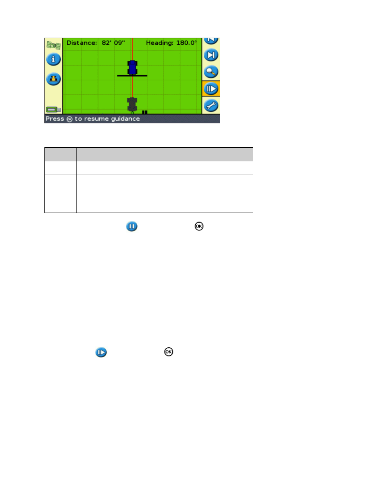
The two status text items at the top of the screen show your current position relative to the pause position:
ITEM DESCRIPTION
Distance The vehicle's current distance from the pause position.
The vehicle's current direction relative to the pause position.
Heading
To pause guidance, select the icon and then press .
When you pause guidance:
Returning to the pause position
1.
2.
For example:
0° = pointing directly toward the pause position
180° = pointing directly away from the pause position
The current guidance line that you were on is displayed, even if you drive onto another swath.•
The pause function remembers your position even if the lightbar is turned off.•
A straight, dotted line is drawn from the pause position to the position of the vehicle.•
Turn the vehicle until the Heading status text item is 0.0° (so you are heading directly toward the pause
position).
Drive forward until the Distance status text item is close to 0.00 m (0' 0"). This means you are nearly
back at the pause position. The paused vehicle outline should be visible on the lightbar screen.
Position the vehicle directly over the paused vehicle outline.3.
Select the icon and then press to resume guidance.4.
37
Page 42

Advanced Mode Guidance
Resetting Guidance
Use the icon to create or load a field or line.
To reset guidance:
Select the icon and press . The Finished With Field? screen appears.1.
Select one of the two options and then press :2.
Yes − To map a new field (see Creating a New Field or Line ) or select an existing field (see
♦
Selecting a Field ).
No − To map a new AB Line (see Adding an AB Line ) or select an existing AB Line in the
♦
current field (see Selecting an AB Line ).
Note: If you select 'Yes', the field is immediately closed. This means that you cannot cancel out of the New
Field wizard and go back to your current field.
Creating a New Field or Line
To create a new field, the New Field wizards takes you through the following steps:
Select the pattern type.1.
Set up the implement.2.
Set up any additional pattern requirements (if necessary).3.
38
Page 43

Name the field (if you are creating a field).4.
Enter record keeping information.5.
Drive and define the guidance line.6.
Step 1: Selecting the pattern type
Note: If the pattern type and implement setup are already correct, just press .
Press to select Pattern Type.1.
Press . The Pattern Type screen appears.2.
Select which of the seven guidance patterns you want to base guidance on. For a description of the
3.
different field patterns, see Guidance Patterns.
Step 2: Setting up the implement (if necessary)
To make optimal use of the EZ−Guide 500 system, correctly configure the implement that is attached to the
vehicle. If the implement is offset and you do not configure it, there will be gaps and overlaps in your coverage.
See Implement Setup.
Step 3: Setting up any additional pattern requirements (if necessary)
Some guidance patterns require additional information:
If you selected ... You need to ...
A+ define the heading.
Headlands define the number of circuits.
39
Page 44
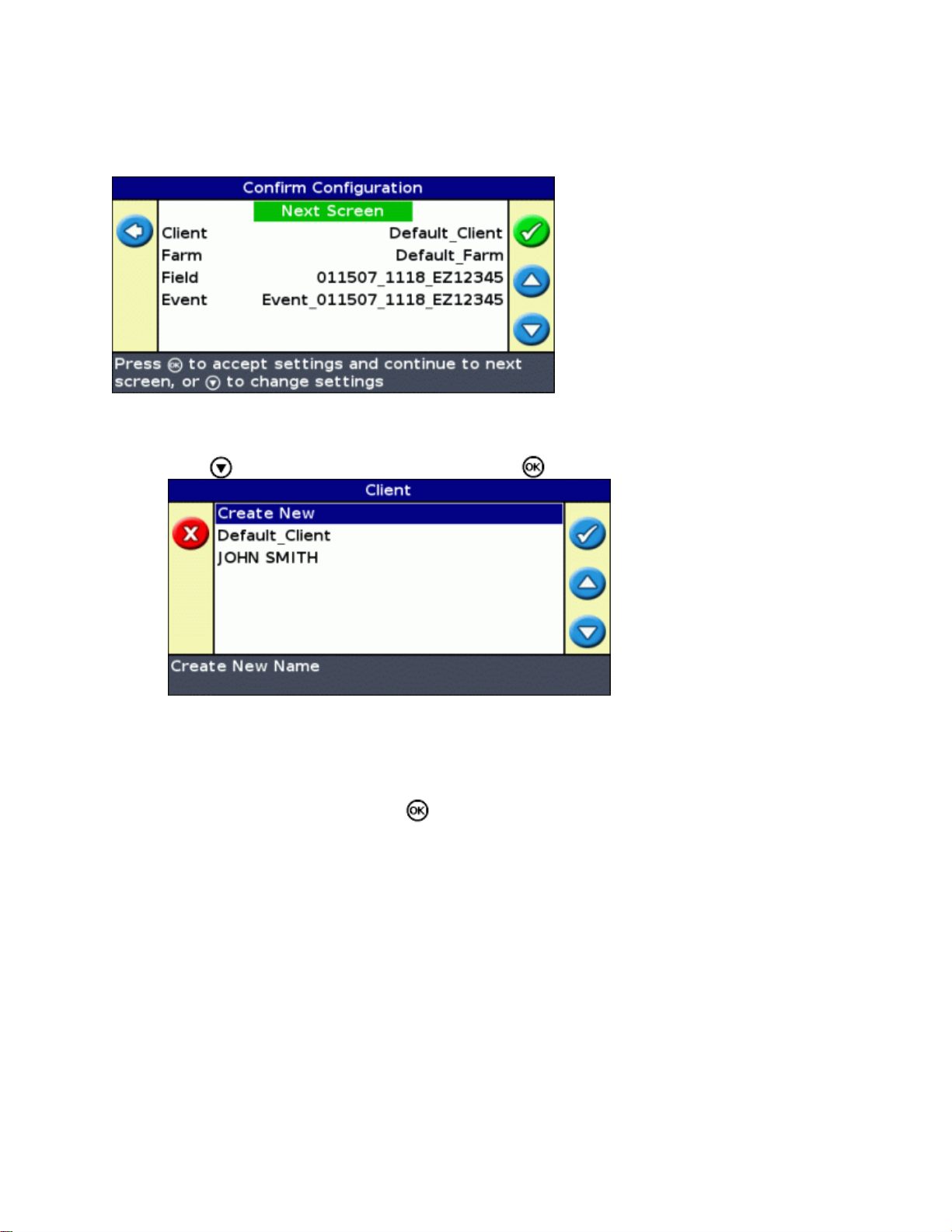
Step 4: Naming the field
When you create a new field in Advanced mode, the first Confirm Configuration screen displays the field name
information. By default, the Client and Farm options show whatever you entered last time:
To rename the field:
Press to select the Client option and then press . The Client screen appears.1.
Select one of the following:2.
Create New − to enter a new name♦
Any other entry − to use an exisitng name♦
Repeat Steps 1 and 2 for the Farm, Field, and Event.3.
Select Next Screen and then press .4.
Note: If the Client, Farm, and Field names already exist, the system displays the message: You must
rename the field with a new name.
Step 5: Entering record keeping information
Note: This feature is available in the firmware version 3.00 and later.
The Record Keeping screen appears:
40
Page 45

On this screen, you can add additional information to aid your record keeping:
ITEM DESCRIPTION
Operator The name of the vehicle operator.
EPA License Number
Harvest Year The year that the crop is going to be harvested.
Farm Location The county or region where the farm is located.
Vehicle The vehicle used in the operation.
Implement The implement connected to the vehicle.
Application Method The application method used (for example, spraying, seeding, or harvesting).
Soil Conditions A description of the state of the soil.
Soil Type A description of the soil type in the field.
Temperature The current temperature (selected with a slider bar).
Humidity The humidity percentage (selected with a slider bar).
Wind Speed The average wind speed (selected with a slider bar).
Wind Direction The average wind direction.
Wind Gust Speed The maximum speed of any wind gusts (selected with a slider bar).
Sky Conditions The amount of cloud cover.
Crop The crop grown in this field.
Target Pests If you are spraying the field, you can record the pest that the spray targets.
Applied Material The material applied to the field.
Custom1 Additional information of your choosing.
Custom2 Additional information of your choosing.
Custom3 Additional information of your choosing.
Custom4 Additional information of your choosing.
(USA) Your EPA license number for spreading restricted−use or state−restricted
pesticides or herbicides.
For more information on entering names with the virtual keyboard, see Naming a Field.
The record keeping entries are optional. When you have entered any record keeping information that you want,
select Next Screen and then press .
Note: These entries are also saved in the summary report.
41
Page 46

Step 6: Driving and defining the guidance line
Depending on the pattern type that you selected, one of the following icons is now available:
(start AB Line, A+, Identical Curve, Adaptive Curve, or Pivot)•
(start Headland)•
(not currently recording FreeForm curve)•
Drive to the start point and then select one of these icons to begin defining guidance.
For more information about the various field patterns, see Guidance Patterns.
Adding an AB Line
To create a new AB Line, the New AB Line wizards takes you through the following steps:
Select the pattern type.1.
Set up the implement.2.
Set up any additional pattern requirements (if necessary).3.
Drive and define the guidance line.4.
Step 1: Selecting the pattern type
Note: If the pattern type and implement setup are already correct, just press .
Press to select Pattern Type.1.
42
Page 47

Press . The Pattern Type screen appears.2.
Select which of the seven guidance patterns you want to base guidance on. For a description of the
3.
different field patterns, see Guidance Patterns.
Step 2: Setting up the implement (if necessary)
To make optimal use of the EZ−Guide 500 system, correctly configure the implement that is attached to the
vehicle. If the implement is offset and you do not configure it, there will be gaps and overlaps in your coverage.
See Implement Setup.
Step 3: Setting up any additional pattern requirements (if necessary)
Some guidance patterns require additional information:
If you selected ... You need to ...
A+ define the heading.
Headlands define the number of circuits.
Step 4: Driving and defining the guidance line
Depending on the pattern type that you selected, one of the following icons is now available:
(start AB Line, A+, Identical Curve, Adaptive Curve, or Pivot)•
(start Headland)•
(not currently recording FreeForm curve)•
43
Page 48

Drive to the start point and then select one of these icons to begin defining guidance.
For more information about the various field patterns, see Guidance Patterns.
Implement Setup
To make optimal use of the EZ−Guide 500 system, correctly configure the implement that is attached to the
vehicle. If the implement is offset and you do not configure it, there will be gaps and overlaps in your coverage.
From the Create New Field or Add AB Line screens:
Select Implement Setup and then press . The Implement Setup screen appears:1.
Select a setting you want to change and then press . The adjustment screen for that setting appears.2.
Press or to adjust the setting and then press . The Implement Setup screen reappears with the
3.
changed setting.
Note: When you need to adjust a value by a larger margin, hold down or to change the value.
After a few seconds the digits will change more quickly.
When you have set all the required implement options, select Next Screen and then press .4.
The implement settings are:
ITEM DESCRIPTION EXAMPLE
Implement
Width
The side−to−side width of the implement.
44
Page 49

Overlap
Left/Right
Offset
Forward/Back
Offset
Set an overlap only if you want the implement to overlap the
previous swath.
If the implement is offset to either the left or the right, set an
offset.
Note: If you configure an implement offset, the guidance line
will be centered on the middle of the implement and the vehicle
will appear to be offline. Use the lightbar LEDs for guidance.
If the implement protrudes to the left, set a left offset. If the
implement protrudes to the right, set a right offset.
If the implement is offset either forward of or back from the
rear of the vehicle, set a forward/back offset.
If the implement is behind the antenna position, set a rear offset.
If the implement is forward of the antenna position, set a
forward offset.
The vehicle and implement will show this offset on the screen.
This compensates for the implement pulling to one side, which
may be caused by variable ground. The effect is similar to that
of left/right offset. Set it when the implement constantly pulls
Implement Draft
Implement
Mount Type
the vehicle to one side. The example shows a left draft.
Note: If you configure an implement draft, the guidance line
will be centered on the middle of the implement and the vehicle
will appear to be offline. Use the lightbar LEDs for guidance.
Use this setting to choose between a hitched (3−point) or
trailing (drawbar) implement.
Whichever mode you select, the implement remains fixed until
the vehicle reaches a speed of at least 3.2 kph (2 mph).
Selecting (Loading) an AB Line
Note: You do not have to actively save an AB Line for it to be stored. AB Lines are stored automatically.
To load an AB Line, do the following:
45
Page 50

Select the AB Line1.
Set up the implement2.
Select the number of headland circuits (if necessary)3.
Step 1. Selecting the AB Line
On the Create new or select old swath screen, choose Select AB Line.1.
If there is only one guidance line in the current field, the main guidance line appears with the guidance
line loaded. See Implement Setup.
If there is more than one guidance line in the current field, the Select Stored AB Line screen appears and
shows the guidance lines that are available to load.
To choose an AB Line to load:2.
Press or to cycle through the available lines.a.
Note: You can select only from those lines that were created within the range shown on the left of
the screen. To increase or decrease the range, press the or function buttons.
Selected the appropriate line and then press . The Select Stored AB Line screen appears.b.
If necessary, change the implement settings.c.
Step 2: Setting up the implement (if necessary)
To make optimal use of the EZ−Guide 500 system, correctly configure the implement that is attached to the
vehicle. If the implement is offset and you do not configure it, there will be gaps and overlaps in your coverage.
See Implement Setup.
Step 3: Selecting the number of headland circuits (if necessary)
If you are loading a Headland, the Headlands Circuits screen appears:
46
Page 51

Press or until you set the appropriate number of circuits.1.
Press . The main guidance screen appears with the headland loaded.2.
Selecting (Loading) a Field
Note: You do not have to actively save a field. Fields are stored automatically.
To load a field, do the following:
Select the field to load.1.
Select or create the event.2.
Select the line to load.3.
Set up the implement (if necessary).4.
These steps are described below.
Step 1. Selecting the field to load
There are two ways you can select a field to load:
Using FieldFinder•
Selecting the Field name from a list•
Using FieldFinder
The FieldFinder option allows you to choose a field from a map view.
Note: The vehicle must be within 200 m of the field for it to appear on screen.
To use FieldFinder:
From the Create new field or select old field screen, select Use FieldFinder .1.
47
Page 52
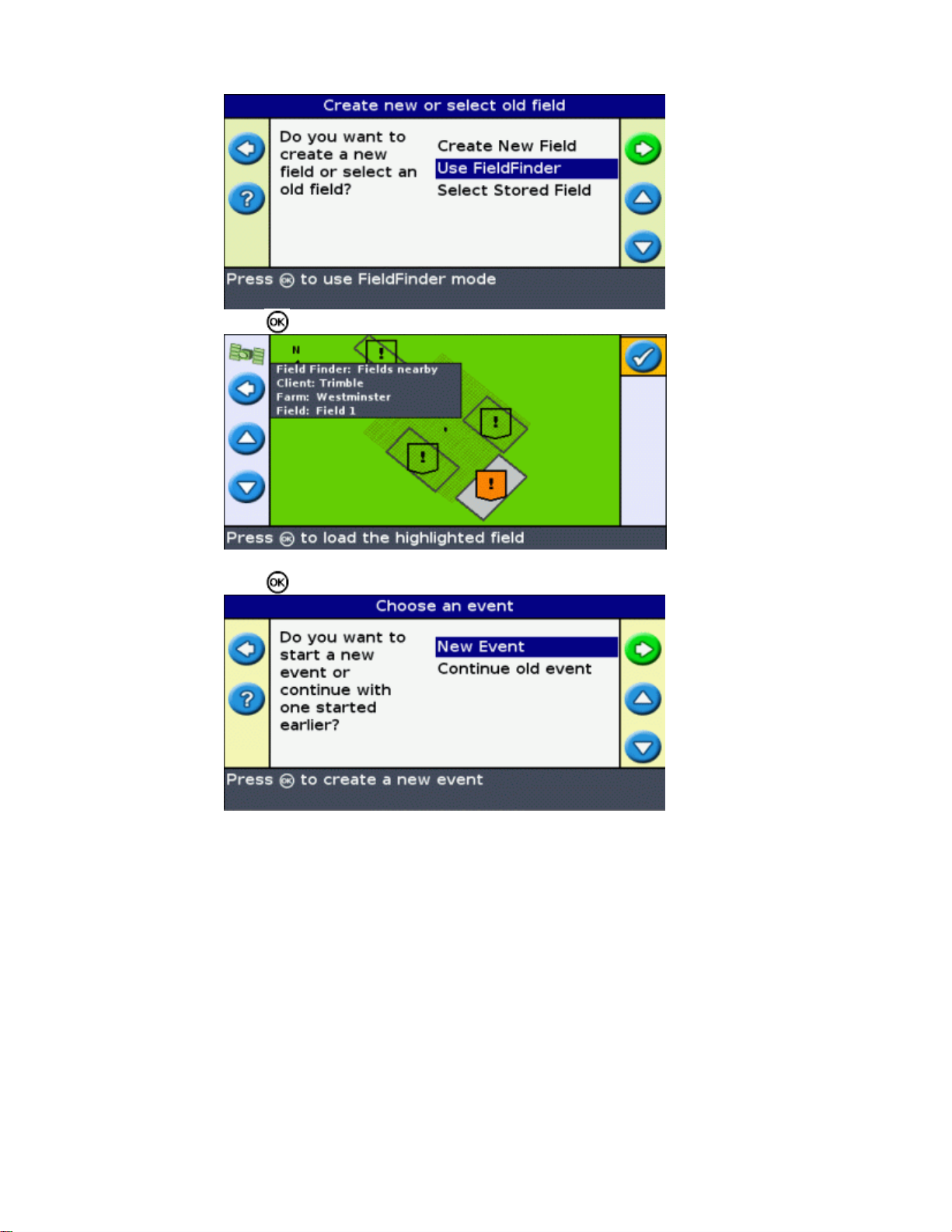
Press . The FieldFinder map view appears.2.
Use the arrow keys on the left of the screen to select the field you want to load.3.
Press .The Choose an event screen appears.4.
Selecting the Field name from a list
You can select the field from a list of names, instead of a map. This can be useful if the lightbar is not
receiving a GPS signal.
To select a field from a list of names:
From the Create new field or select old field screen, select Select Stored Field .1.
48
Page 53

Press . The Select Stored Field screen appears.2.
Select the client.3.
Press to select Client and press . The Client screen appears.a.
Press or until you select the desired Client name.b.
Press . The Select Stored Field screen reappears.c.
Select the farm, using the same process as for client.4.
Select the field, using the same process as for client and farm.5.
Press to select Continue .6.
Press .The Choose an event screen appears.7.
49
Page 54

Step 2: Selecting or creating the event
Press or until you select either New Event or Continue old event.1.
Press .2.
If you selected New Event, you must enter a name for the new event.
Note: If you want to create a new line in this field, load an existing line, select the icon and then create a
new line.
One of the following occurs:
If there is only one saved line, it is automatically selected. See Implement Setup.•
If there is more than one saved line, the Select Stored AB Line screen appears.•
Step 3: Selecting the line to load
Press or one or more times until you select the appropriate line.1.
Press . The Select Stored AB Line screen appears.2.
50
Page 55

Step 4: Setting up the implement
To make optimal use of the EZ−Guide 500 system, correctly configure the implement that is attached to the
vehicle. If the implement is offset and you do not configure it, there will be gaps and overlaps in your coverage.
See Implement Setup.
If you do not need to change the implement configuration, select Next Screen and then press .
51
Page 56

Advanced Mode Additional Information
Views
There are two possible views when you are driving in the field in Advanced mode:
Perspective map view Plan map view
The view that is shown is controlled by the view mode:
ITEM DESCRIPTION
Auto Headlands
(default)
Auto Engage
Manual
The Auto Headlands and Auto Engage view modes control which view you see. Manual mode enables you to
change the view yourself.
Changing the view mode
To change the view mode, select Configuration / System / Display / View.
Shows the perspective map view on swaths and the plan map view in headlands.
Shows the perspective map view when the EZ−Steer system is engaged and the plan map
view when the system is disengaged.
You can manually change between the perspective map view and the plan map view
using the action icon.
Night Mode
To improve the visibility of the screen during night−time operations, you can change the color scheme.
52
Page 57

To change to night mode, select Configuration / System / Display / Color Scheme and select Night Mode .
Nudge
Nudge a guidance line if you need to correct for:
GPS position drift when returning to the field for guidance, for example, after pausing or turning the unit
•
off and on
GPS satellite constellation changes while driving in the field•
Each nudge moves the guidance line by the Nudge Increment value. For example, if the Nudge Increment is set to
3" and you press twice, the total nudge distance is 6" to the right.
The nudge left and nudge right icons
The Nudge function moves the guidance line slightly to the left or right, relative to your vehicle. Use it if you can
see that the vehicle is exactly on−line, but the lightbar is showing that you are slightly offline:
Nudge is always applied to the guidance line relative to the vehicle heading. To nudge, press or one or
more times until you select the nudge left or nudge right icon and then press the button.
In Easy mode, you cannot adjust the amount of each nudge. The default value is 3 cm (1").
You can change other Nudge features in Advanced mode.
Changing the nudge increment value
The default nudge increment value is 3 cm (2").
To change the amount by which nudge increases, select Configuration / System / Guidance / Nudge Increment.
53
Page 58

Note: The maximum Nudge Increment value is 30 cm (12").
To reset the nudge distance to 0, select Configuration / System / Guidance / Reset Nudge.
Viewing the current amount of nudge
There are two ways to view the current amount of nudge that has been applied:
The nudge value is displayed on the Tip/Message bar at the bottom of the screen while a nudge icon is
•
highlighted
The first information tab shows the current nudge value. Press the function button.•
Resetting nudge after each row
You can configure the lightbar to reset the nudged position each time you change rows:
Select Configuration / System / Guidance / Clear Nudge at Swath End.1.
Select On and then press .2.
Each time you move from one swath to the next, the nudge value will reset to 0, and the swaths will return to their
original position.
The shift icon
Shift moves the guidance line directly to the vehicle position.
Shift enables you to permanently update the position of the line. With the shift and save mode, you can move the
54
Page 59

line and save it. This can be useful for higher accuracy work, for example, to offset planting by half a swath width
from one season to the next.
To shift the lines:
Drive the vehicle along the line that you want to map the guidance to.1.
Note: If you are driving at an angle of more than 10 degrees from the current swath, an error message
appears. You must drive at almost the same angle as the guidance line.
Select the action icon. The Shift to Here screen appears:2.
Select one of the following:3.
Item Description
Cancel Exit without moving the guidance line
Shift but Don't Save
Shift and Save New
The line moves to your current location, but when you exit the field the previous
line position is retained
The line moves to your current position and is permanently saved in the new
location
Configuring the Lightbar
Setting the LED brightness
You can adjust the brightness of the LEDs on the lightbar. In bright sunlight, increase the brightness to make the
LEDs more obvious. In darker conditions, for example, driving at dusk, you can lower the brightness settings to
make the LEDs less intense.
To change the LED brightness, select Configuration / System / Display / LED Brightness.
Setting the backlight brightness
The backlight brightness controls the brightness of the lightbar screen.
To adjust the setting, select Configuration / System / Display / Backlight.
55
Page 60

Setting the information tab transparency
For a description of the information tabs, see Information tabs.
The information tabs are transparent. To change the level of transparency, select Configuration / System / Display
/ Status Popup Transparency.
10 represents a solid black tab; 1 is barely visible.
Setting the LED mode
There are two LED modes:
Mode Description
Chase (default)
Pull
To change the LED mode, select Configuration / System / Guidance / LED Mode.
LED spacing
The LED spacing is the distance that each LED represents. The default LED spacing is 15 cm (6").
To adjust the LED spacing, select Configuration / System / Guidance / LED Spacing.
Setting the units
The units that you selected during the Quick Start Wizard are set as the units for the lightbar. The default units are
US/imperial.
To change the units, select Configuration / System / Display / Units.
Setting the time zone
Chase the LEDs to stay online. The LEDs represent the swath location relative to the vehicle.
For example, if the vehicle moves offline to the left, the lit LEDs move right.
Center the LEDs to stay online. The LEDs represent the vehicle position relative to the swath.
For example, if the vehicle moves offline to the left, the lit LEDs also move left.
The lightbar receives the time from the GPS signal, which transmits UTC (Coordinated Universal Time, formerly
known as Greenwich Mean Time).
To enter your time offset from UTC so that the lightbar can calculate your local time, select Configuration /
System / Display / Time Zone.
Common time zones are listed below.
Location Standard time offset Daylight savings time offset
US Eastern Time −5:00 −4:00
56
Page 61

US Central −6:00 −5:00
US Mountain −7:00 −6:00
US Pacific Time −8:00 −7:00
Australia East +10:00 +11:00 (except Queensland)
Australia Central +9:30 +10:30 (except Northern Territory)
Australia West +8:00 +9:00
A positive timezone indicates a zone that is ahead of Greenwich, England. A negative timezone is behind.
Driving on Large Fields
At distances greater than 10 km (6.2 miles) from the original AB Line, the curvature of the Earth's surface can
cause a reduction in GPS position accuracy. Consequently, the lightbar does not support more than 1024 swaths to
the left and 1024 swaths to the right of the original AB Line.
If you need to create more than 1024 swaths either to the left or the right of the AB Line, do one of the following:
Create a second AB Line•
Use the A+ pattern•
This will ensure that you maintain the highest level of steering accuracy.
Driving Tight Turns
By default, the EZ−Guide 500 system smooths out tight turns. This makes it easier for the driver (or the EZ−Steer
or AgGPS Autopilot system) to follow the curve without overshooting the turn. Because the guidance line is
being gradually smoothed out, this can result in minor skips in coverage between the swaths.
To configure curve smoothing, select Configuration / System / Guidance / Minimum Turn Radius Mode. There are
three options:
ITEM DESCRIPTION
Automatic
Manual
Disabled
The minimum turn radius is the larger of 80% swath width or 10 meters. Curves that are tighter than
the minimum turn radius are smoothed.
User−configured minimum turn radius. Curves that are tighter than the minimum turn radius are
smoothed.
Curve smoothing on tight turns is disabled. (Tight turns are curves with a radius of less than 3 m (10
ft)).
CAUTION: If you disable curve smoothing, the EZ−Steer 500 system or the AgGPS Autopilot
system may not be able to autosteer around the tighter turns. Be careful when you disable curve
smoothing.
57
Page 62

The lightbar displays a warning when you approach a tight turn. You may want to disengage the autosteer system
and slow down to ensure that you turn smoothly and do not tangle the implement.
To adjust the angle of turn that triggers that warning:
Select Configuration / System / Guidance / Tight turn alert threshold.1.
Select a value from 1 to 10.
2.
A low value triggers the warning even on gentle curves while a high value triggers the warning only on
tight curves.
The default value is 7.
Adding a Time Delay to Coverage Logging
There may be a delay between the time when you start or stop drawing coverage onscreen and the time when the
implement actually starts or stops coverage. For example, some spray valves can take 1.5 seconds to open or
close.
To compensate for this, you can add a time delay to the drawing of coverage logging, so that the lightbar more
accurately reflects what is actually occurring.
To add a time delay to the drawing of coverage logging, select Configuration / System / Guidance / Coverage
On/Off Delay.
When you engage coverage logging, the system waits this delay time before beginning to draw the coverage
onscreen.
When you disengage coverage logging, the system waits this delay time before stopping drawing coverage
logging.
Configuring Coverage Logging
You can select when coverage logging engages:
ITEM DESCRIPTION
Disabled Coverage logging is disabled.
Manual
Engaged Coverage logging is on when an automated steering system is engaged.
Switch Coverage logging is enabled with an external switch.
To change when coverage logging is enabled:
Coverage logging is manually engaged or disengaged with the icon.
In Advanced mode, select Configuration / System / Guidance / Coverage Logging. The Coverage
1.
Logging screen appears.
Select the appropriate setting and then press .2.
58
Page 63

Setting the Look Ahead Value
The Look Ahead time predicts your future vehicle path to allow for reaction time and vehicle turn speed.
For larger vehicles that take longer to turn, increase the time.
Note: For 4WD articulated tractors, always set the Look Ahead time to 0 seconds.
To adjust the Look Ahead value, select Configuration / System / Guidance / Look Ahead.
Enabling Speed Pulse Output (Radar)
The EZ−Guide 500 lightbar guidance system can output simulated radar pulses at a pre−defined speed pulse
output rate. This can be useful to:
replace the radar / true ground speed sensor for speed on the vehicle.•
send speed to any other agricultural device requiring speed pulses, for example, yield monitor or variable
•
rate controller.
To use speed pulse output, you need a radar sensor cable kit. To purchase one, contact your local reseller.
Connecting a device to receive speed pulses
To connect the lightbar to a spray controller:
Attach the external interface cable (P/N 62749) to the COM port of the lightbar.1.
Attach the radar sensor cable to the external interface cable.2.
If required, connect a spray switch into the WeatherPack connector on the radar sensor cable using a
3.
fly−lead.
Configuring the lightbar
Select Configuration / System / Radar Output:
1.
.
Configure the radar settings:2.
Radar Enabled must be On.♦
Radar Frequency Rate is the output rate expected by your device. Most Raven and Midtech
♦
controllers use 58.94 Hz/mph (34.80 Hz/kph).
59
Page 64

Setting up a controller
On a Raven controller:
Make sure that the speed input is set to Speed Radar SP2.1.
You usually choose the speed input setting when you first calibrate the unit; the choices given in most
Raven controllers are SP1 or SP2. SP2 is the correct setting for Speed Radar inputs. For more information
on how to check this setting, refer to your variable rate controller instruction manual.
Make sure that the speed calibration value is set correctly. For the most accurate results, recalibrate the
2.
unit to match the lightbar output.
For information on how to calibrate the unit, refer to the controller instruction manual.
Note: To check the accuracy of your current settings, compare the speed value indicated on the lightbar guidance
system with that on the spray controller.
On a Midtech controller:
Make sure that the speed calibration value is set correctly. For the most accurate results, recalibrate the
1.
unit to match the lightbar guidance system output.
For information on how to calibrate the unit, refer to the controller instruction manual.
Note: To check the accuracy of your current settings, compare the speed value indicated on the lightbar guidance
system with that on the spray controller.
Recording events
The EZ−Guide 500 lightbar can record events for playback. Only use this feature if directed to by your support
provider.
Restoring the Default Lightbar Settings
You can restore all of the lightbar settings back to the factory defaults.
Select Configuration / System / Restore Defaults. The Restore Defaults screen appears.
Note: Your field information remains unchanged.
60
Page 65

Advanced Mode GPS Corrections
Configuring the GPS Corrections
The term GPS corrections refers to the type of GPS signal that you receive. There are a number of different
corrections, each of which has a different level of accuracy and different requirements.
ITEM DESCRIPTION
External Corrections Enables the lightbar to accept external RTCM corrections for DGPS positions.
WAAS corrections are an overlay to the normal GPS signal to improve accuracy.
WAAS is available only in the United States of America and can be used free.
WAAS (Wide Area
Augmentation
System)
EGNOS (European
Geostationary
Navigation Overlay
Service)
When using WAAS corrections, the EZ−Guide 500 system downloads the WAAS
ionosphere model within the first 10 minutes of operation, which improves accuracy
significantly. If you turn off the lightbar for less than 20 minutes and restart it, the
position drift is limited. If you turn of the lightbar for more than 20 minutes and then
restart it, the WAAS ionosphere model needs to be downloaded again. This can result
in absolute position errors of up to 3 m (10 ft) within the first 10 minutes.
EGNOS corrections are an overlay for normal GPS signals. They are available only in
Europe and can be used free.
OmniSTAR VBS
OmniSTAR XP
OmniSTAR HP
(High Performance)
RTK (Real Time
Kinematic)
Note: At mid latitudes, the GPS cross−track errors that occur when you drive East−West are typically double the
cross−track errors that occur when you drive North−South. This is a characteristic of all GPS receivers and
guidance systems, and occurs because the GPS satellite orbits do not go over the poles. For GPS system status
details, go to http://www.navcen.uscg.gov/ado/GpsActiveNanu.asp.
The lightbar is initially configured to use the internal GPS receiver with WAAS/EGNOS. It will automatically
detect the appropriate satellites.
To change the GPS corrections:
Select Configuration / System / GPS / GPS Setup / GPS Correction Source and then press . The GPS
1.
Correction Source screen appears:
Accurate to within 100 cm (12"). To receive the OmniSTAR corrections you must pay
for a subscription.
Accurate to within 20 cm (8"). To receive the OmniSTAR corrections you must pay for
a subscription. This requires the Z+ antenna.
Accurate to within 10 cm (4"). To receive the OmniSTAR corrections you must pay for
a subscription. This requires the Z+ antenna.
RTK is the highest accuracy correction. It requires a local base station. This requires the
Z+ antenna.
61
Page 66

Select the appropriate correction method and then press . The GPS Source screen reappears. The
2.
correction appears as the Source.
Press to select Next Screen and then press .3.
Configuring WAAS/EGNOS
To configure WAAS or EGNOS corrections, set each of the fields on the WAAS/EGNOS Settings screen:
ITEM DESCRIPTION
Correction
Limit
Satellite
Satellite
Health
Configuring OmniSTAR corrections
The OmniSTAR XP/HP or VBS corrections require a paid subscription. For more information, go to
www.omnistar.com.
To configure OmniSTAR XP/HP corrections:
The time that the lightbar can run without receiving an updated GPS position, before it drops
guidance.
The correction satellite that the lightbar will use. To automatically select the satellite, select
Auto Select. Otherwise, you can select a specific satellite.
How the lightbar searches for the satellite:
On − The system searches for the satellite, regardless of the region or the satellite health.
Off − The system does not search for the satellite.
Heed Health − The system searches for the satellite if the satellite is within the appropriate
region and is healthy.
Ignore Health − The system searches for the satellite if the satellite is within the appropriate
region, regardless of satellite health.
62
Page 67

Adjust the OmniSTAR satellite information, if necessary.1.
Select Continue and then press . The OmniSTAR Satellite Settings screen appears:2.
Press the function button. The list of OmniSTAR contact telephone numbers appears.3.
Telephone OmniSTAR in your region and tell them your Unique User ID. This is displayed on the
4.
Subscription Setup screen. OmniSTAR will guide you through the process of activating your subscription.
If you are using OmniSTAR XP/HP, set the OmniSTAR engage accuracy.5.
Note: Engage Accuracy is an absolute repeatable engage accuracy limit. To configure a pass−to−pass
accuracy limit, double the Engage Accuracy value.
For example, for 4" pass−to−pass engage accuracy, configure the Engage Accuracy value to 8".
Enable or disable the Autoseed fast restart technology. The fast restart technology converges the
6.
corrections more quickly. It is available only if the vehicle has not moved since the lightbar was turned
off.
63
Page 68

Confirm the OmniSTAR settings.7.
The OmniSTAR XP/HP or VBS corrections are now configured.
Configuring RTK
Note: If you want to use RTK corrections and output NMEA messages at the same time, you must connect the
radio to the COM port on the lightbar and the NMEA device to the AUX port. Set the NMEA port to AUX in the
NMEA output Port Parameters screen.
Note: You should turn off coverage logging before changing RTK configuration settings. Otherwise, you may get
a jump in the coverage logging due to a momentary loss of GPS corrections while changing settings.
To configure RTK corrections, select the appropriate protocol:
ITEM DESCRIPTION
CMR For TSIP, European Pac Crest, or SiteNet 450 radios
TrimbleRadio For the SiteNet 900 radio
The remaining RTK options change depending on which protocol is selected.
CMR protocol
Set the Baud Rate, Data Parity, and Stop Bits for the rover radio.1.
64
Page 69

Select Next Screen and then press .2.
RTK corrections are configured.
TrimbleRadio protocol
Set the Radio Network Number to match the network ID number of the base station. If the network IDs
1.
do not match, the radios will not communicate.
Select Next Screen and then press .2.
RTK corrections are configured.
Configuring the GPS Limits
The GPS Limits screen enables you to adjust several of the GPS signal strength tolerances. If you are having
trouble getting GPS reception, you may be able to receive a signal by lowering the tolerances, but at the cost of
lowering signal quality and therefore lowering GPS accuracy.
To adjust the settings, select Configuration / System / GPS / GPS Limits.
Select the appropriate setting and then press . The limit adjustment screen appears.1.
65
Page 70

Adjust the value and then press .2.
ITEM DESCRIPTION
Elevation refers to the angle at which a satellite appears in the sky (higher is
Minimum Elevation
better). The Minimum Elevation setting is the minimum angle in the sky at
which the lightbar will acknowledge satellites.
Minimum SNR
Use SBAS satellites in the
position fix
Minimum Satellites This is the minimum number of satellites required to provide GPS guidance.
Maximum HDOP
Minimum Fix Quality This is the minimum correction level required to provide GPS guidance.
Force GPS Iono
OnPath Filter
SNR (Signal to Noise Ratio) is a measure of the quality of a GPS signal. It is
the ratio of useful information received to noise. A high SNR value is better.
You can use WAAS SBAS satellites to calculate standard GPS positions. This
means that if you can see six standard GPS satellites and two WAAS satellites,
the lightbar uses all eight satellites to calculate the GPS position.
If you are working in fields with obstacles (for example, trees), the additional
SBAS satellites will improve the fix quality.
Note: This option does not work with EGNOS satellites, or OmniSTAR or RTK
corrections.
The Maximum HDOP (horizontal dilution of precision) is a measure of
accuracy based on the geometry of the satellites in the sky. If the satellites are
near each other in the sky, the HDOP is higher (lower is better).
Forces the lightbar to use the GPS iono map. Turn this option On at higher
latitudes (above 50 North) if the lightbar reports Hybrid Iono for longer than 15
minutes after startup
The filter detects and eliminates position jumps that can occur when a satellite
is obscured, for example, by trees.
Configuring NMEA message output
NMEA (National Marine Electronics Association) messages are a standard format that enables GPS devices to
communicate.
The lightbar can output NMEA messages. This means that the lightbar can communicate with other devices, even
those created by other manufacturers, so long as the other device is also compatible with NMEA messages.
66
Page 71

To configure NMEA output, select Configuration / System / GPS / NMEA Output.
Set the NMEA output port option to the lightbar port that the NMEA device is connected to.1.
Set the lightbar port parameters.2.
Tip − To be able to communicate, the parameters must match those of the device.
Select Next Screen and then press . The Message Selection screen appears.3.
Set the various message formats to On or Off, depending on whether they are required.4.
Select Next Screen and then press .5.
If you turned GGA on, then select the number of decimal places in the GGA message.6.
Note: Some external devices cannot read the GGA message if there are too many decimal places in the
string.
Outputting NMEA messages with RTK corrections
If you are using RTK corrections and outputting NMEA, you must connect the NMEA device to the AUX port.
Use the port expansion cable (P/N 62609) and the accessory cable (P/N 63076):
67
Page 72

ITEM DESCRIPTION
1 External interface cable (P/N 62749)
2 To RTK radio
3 RTK radio cable
4 EZ−Guide 500 power cable (P/N 62817)
5 Port expansion cable (P/N 62609)
6 Connect COM 2 port connection cable (P/N 63076) and then NMEA device
External Receiver Support
The EZ−Guide 500 lightbar can recieve GPS positions from TSIP−compatible recievers. This enables you to use
any of the correction types available on your receiver, including OmniSTAR, Beacon, and RTK.
The following TSIP−compatible recievers are supported by the EZ−Guide 500 lighbar:
Trimble Case IH Ag Leader New Holland
AgGPS 252 AFS 252 GPS 5100 NH 252
AgGPS 332 − − −
68
Page 73

To enable TSIP messages as the correction source:
Connect the receiver to the lightbar and then turn them on.1.
Select Configuration / System / GPS / GPS Setup.2.
Change the GPS Correction Source option to Ext. TSIP.3.
Select Continue and press . The Connecting to External Receiver screen appears. The lightbar
4.
connects to the TSIP receiver. The message Connection Established appears.
Press . The External DGPS Source screen appears, showing the available corrections on the reciever.5.
Select the appropriate correction source and then press . The wizard for that correction type appears.6.
Note: When the lightbar is receiving GPS positions from the TSIP−compatible receiver, additional entries appear
on the Info tab.
Using OmniSTAR corrected positions over TSIP
To configure the lightbar to use OmniSTAR corrected positions from a TSIP receiver:
When the OmniSTAR Satellite Settings screen appears, press to view the Help.; It lists the available
1.
satellites and their frequencies and baud rates.
Write down the frequency and baud rate for the appropriate satellite and then press . The OmniSTAR
2.
Satellite Settings screen re−appears.
Enter the satellite frequency and baud rate.3.
Press . The Subscription Setup screen appears:4.
Press . The help displays a list of contact phone numbers for OmniSTAR.5.
Phone OmniSTAR and then press . The Subscription Setup screen re−appears.6.
Tell the OmniSTAR representative the number that is listed in the Serial Number field. They will enable
7.
your receiver.
69
Page 74

Note : Do not manually disconnect the lightbar from the receiver. The lost signal causes the lightbar to perform
an incorrect fast restart.
When the lightbar receives OmniSTAR corrections from a TSIP−compatible receiver, the convergence time is
reported differently.
Using RTK corrected positions over TSIP
When you use RTK positions from an external receiver, you can configure the network ID using the Network ID
setting.
On the main map screen, the Info tab shows a diagnostic called Link Quality . This describes the quality of the
radio signal, and as a result the RTK signal.
Depending on the quality of the signal coming in, the Link Quality item will show one of the following indicators:
Excellent•
Good•
Fair•
Poor•
70
Page 75

Advanced Mode Data Management
USB Drive Compatibility
The EZ−Guide 500 lightbar saves data to and from a USB drive using a FAT file system.
Caution − Multi−function devices, for example iPods or MP3 players, are not compatible with the lightbar. Do
not reformat these devices to use the FAT file system, as this may delete their firmware and prevent them from
operating correctly.
The following drive is compatible with the lightbar:
Lexar Firefly 1 GB (P/N 64268−1G). For more information, contact your local reseller.•
The following drives are not compatible with the lightbar:
Apple Ipod•
MP3 player•
Kingston flash drive•
PNY Attache flash drive•
USB extension cables•
USB to CompactFlash adaptors•
Note: Newer versions of the SanDisk Micro Cruzer USB drive are not compatible. Versions of the drive that have
worked in the past will continue to work.
Note − Because USB to CompactFlash card adaptors are not supported, AgGPS Autopilot system users must
transfer field data from their CompactFlash cards to the USB drive using a laptop or office computer.
If you are having trouble importing or exporting data to a USB drive, reformat it with the FAT file system.
Note − This deletes any data on the drive. Before you complete these steps, copy any data that you want to keep.
Insert the USB drive in the USB port of an office computer. The drive is recognized by the computer.1.
Open the File Manager.2.
Right−click on the USB drive letter and then select Format. The Format Removable Disk dialog appears.3.
71
Page 76

In the File system list, select FAT and then click Start.4.
The USB drive is formatted with the FAT file system.
Inserting a USB drive
You can connect a USB drive to the USB port on the back of the lightbar:
Ensure that the lightbar is turned off.1.
Insert the USB drive into the USB port.2.
Turn on the lightbar.3.
Note: To reduce any delay caused by the lightbar scanning the USB drive, keep the number of fields on the USB
drive to a minimum.
Removing a USB drive
Caution − If you remove a USB drive from the lightbar while the lightbar is turned on, you risk corrupting the
data. To avoid this, do the following:
Turn off the lightbar.1.
Remove the USB drive from the USB port.2.
Getting Data from the USB Drive
You can get data from a USB drive:
72
Page 77

Connect the USB drive. See USB Compatibility1.
Select Configuration / Data Management / Manage Fields / Get Fields from USB.2.
Do one of the following:3.
Select the specific client, farm, and field to import.♦
Select All to get all of the data in a category to the USB drive.♦
Note: If you select All, you do not need to select the later options.
Select Import Files and then press . A warning message appears.4.
Press to continue. A screen with an hourglass appears.5.
The files are imported from the USB drive.
Importing Data from the AgGPS FieldManager Display
The AgGPS FieldManager display uses a CompactFlash card to record field data. The EZ−Guide 500 system uses
a USB drive. Therefore, the storage devices are not interchangeable.
To import data from the AgGPS FieldManager display to the EZ−Guide 500 system:
Insert the FieldManager display data card into the card reader of your office computer.1.
Copy the field data to a temporary directory on the computer.2.
Insert the EZ−Guide 500 system USB drive into the office computer.3.
Copy the field data from the temporary directory to the USB drive.4.
Insert the USB drive into the lightbar.5.
On the lightbar, select Configuration / Data Management / Manage Fields / Get Fields from USB.6.
You cannot import old field data into the EZ−Guide 500 system from the AgGPS 170 Field Computer or an RDL.
Sending Data to the USB Drive
You can export data to a USB drive. This can be useful for backing up your data, or viewing the data in a GIS
software application.
Note: The lightbar will not send data to a USB drive that is over 90% full.
Connect the USB drive. See USB Compatibility1.
Select Configuration / Data Management / Manage Fields / Send Fields to USB. The Send Fields to USB
2.
screen appears:
73
Page 78

Do one of the following for each of the Client, Farm, and Field options:3.
Select the specific item to export.♦
Select All to export all of the entries.♦
Select Export Files and then press . A warning screen appears.4.
Press to continue. A screen with an hourglass appears:5.
The data is exported.
Exporting large fields
Tip: To export a large field, create a temporary new A+ field with no logging in it and then export the large field.
This will ensure that the large field is correctly closed before it is exported.
Clearing Storage Space
To avoid the lightbar's internal memory from becoming full over time, use one of the following methods available
on the Data Management screen:
Occassionally delete old fields.•
Export data to a USB drive and then store it on an office computer.•
Delete the coverage logging. See below.•
Deleting Fields
You can delete fields that you no longer require:
Select Configuration / Data Management / Manage Fields / Delete Selected Fields.1.
74
Page 79

Do one of the following:2.
Select the Client, Farm, and Field to delete.♦
Select All from one of the categories to delete all the entries under that heading.♦
Select Delete Files and then press . A warning message appears.3.
Press to continue. A screen with an hourglass appears.4.
The files are deleted.
Deleting coverage logging
You can delete coverage logging to free up space in the lightbar's internal memory:
From the main guidance screen, select the icon and then press . The Configuration screen
1.
appears.
Select Configuration / Data Management / Manage Fields / Delete Coverage Logging.2.
Select the Client, Farm, Field, and Event. If you choose to delete the coverage logging from all of the
3.
fields in a farm, the events are deleted automatically.
Select Delete Files and then press . A warning message appears.4.
Press to continue. A screen with an hourglass appears.5.
The coverage logging files are deleted.
Exporting Diagnostic Logs
The EZ−Guide 500 system records operating information in diagnostic logs. You can export these logs to a USB
drive:
Connect the USB drive. See USB Compatibility1.
Select Configuration / Data Management / Manage Diagnostic Logs / Export Diagnostic Logs to USB.
2.
A screen with an hourglass appears for a few seconds while the files are exported. A message appears to
confirm that the diagnostic logs have been exported.
Field Name Structure
The EZ−Guide 500 system stores data in a directory hierarchy of client, farm, field, and event.
ITEM DESCRIPTION
Client The customer for whom the work is being done
Farm A collection of "fields" (see below)
Field A specific area of land where events are carried out
Event The event or application that is being applied on a particular "field" (see above). For example:
75
Page 80

− Spraying
− Harvesting
A client may have several farms, each of the farms may consist of several fields, and each field may be broken
into a number of events.
Default Field Names
By default, the client, farm, field, and event names are automatically generated. The default names are:
ITEM DESCRIPTION
Client Default_Client
Farm Default_Farm
Field Date _ Increment _EZ SerialNumber
Event Event_ Date _ Increment _EZ SerialNumber
Note: Date is in the format YYMMDD and Increment is a number that increases for each new field. Only the last
five digits of the serial number are used.
Naming a Field
When you create a new field in Advanced mode, the Confirm Configuration screen displays the default client,
farm, field, and event names.
To name the client:
Press to select the Client option and then press . The Client screen appears:1.
76
Page 81

Select one of the following:2.
Create New − Select Create New to enter a new name.♦
Any other entry − Any other entries on the list are recent fields.♦
Repeat Steps 1 and 2 for the Farm, Field, and Event.3.
Press until you select Next Screen and then press .4.
If the field does not already exist, it is now named.
If the field already exists, the system displays a warning message. Go back and rename the field.
Entering a new field name
Press to select Create New and then press . The Create New screen appears:1.
Move the cursor to the appropriate letters and then press .2.
Select and then press to accept the name and return to the previous screen. The new name
3.
appears in the option that you selected.
System Configuration Files
Once you configure the system, you can save and load those configuration settings. Saved system configurations
can be useful if you want to:
move the lightbar from one vehicle to another•
drive in the same vehicle but with different settings (for example, with a different implement)•
try adjusting the settings to improve performance•
77
Page 82

Saving the system configuration
Select Configuration / Data Management / Save/Load Configurations / Save Current Configuration.1.
Select one of the following:2.
Save to internal memory − Save the current configuration to the lightbar internal memory.♦
Save to USB drive − Save the current configuration to a USB flash drive.♦
An existing configuration − Saves the current configuration over the existing one. A warning
♦
message appears. Press to proceed, or press the function button to exit without saving.
Loading a system configuration
Select Configuration / Data Management / Save/Load Configurations / Load a Configuration. The Load a
1.
Configuration screen appears.
Select the configuration to load from the list and then press .2.
A message appears to warn that you will load the configuration over the current configuration. Press
to proceed, or press the function button to exit without loading.
Summary Report
The lightbar can produce multi−page field summaries that contain a field map and report.
These summaries are in RTF format and can be viewed on an office computer. The summary report is
automatically created when you close the field. (A field is closed when you run the New Field Wizard). The
summary report has the same name as the field.
Note: To view the graphics in the files, you may need to install the Microsoft® Word viewer utility from the
EZ−Guide 500 Documentation CD.
The summary shows the current implement width. If you create a summary of a field that was driven with an
implement of a different width, change the current implement width to match that of the field before you
78
Page 83

continue.
Note: A field must contain coverage for you to be able to generate a Summary Report.
To manually create a field summary:
Open the appropriate field.1.
From the main guidance screen, press one or more times until you have selected .2.
Press . The Configuration screen appears.3.
From the Configuration screen, select Data Management / Summary Reports. The Summary Reports
4.
screen appears.
Select Create Summary Report Now and then press . The summary report is saved to the lightbar's
5.
internal memory.
To export the summary reports to the USB drive:
From the main guidance screen, press one or more times until you have selected .1.
Press . The Configuration screen appears.2.
From the Configuration screen, select Data Management / Summary Reports. The Summary Reports
3.
screen appears.
Ensure that a USB drive is inserted into the EZ−Guide 500 USB slot.4.
Select Send Summary Reports to USB and then press . The Send Summary Reports to USB screen
5.
appears.
Do one of the following:6.
Select the name of the summary report to send.♦
Select All to send all summary reports to the USB drive.♦
Select Send and then press .8.
To view the summary report:
Insert the USB drive into an office computer.1.
On the USB drive, locate the appropriate RTF file in the \AgGPS\Summaries\ directory.2.
Double−click on the field that you want to load.3.
To save the file, copy it to the office computer.
Viewing/Editing Data with Office Software
The EZ−Guide 500 lightbar guidance system saves field information in shapefile format. Each shapefile is made
up of three files:
example.shp − position information•
example.shx − index file that links the position information with its attributes•
example.dbf − feature attributes•
Keep these files together when you copy or move the data.
79
Page 84

Data collected by the EZ−Guide 500 lightbar can be opened directly into the EZ−Office software that is available
on the EZ−Office Software CD or from www.EZ−OfficeSoftware.com.
Upgrading Firmware
This section describes how to upgrade:
the EZ−Guide 500 lightbar firmware•
the EZ−Boom controller firmware•
Upgrading the lightbar firmware
Before you begin to update the firmware in the lightbar, check which firmware version is currently installed:
Select Configuration / About the EZ−Guide.1.
Check the Version number:2.
This is the firmware version. If the number is 1.00.xxx.x, you have firmware version 1.00. If the number
is 1.01.xxx.x, you have firmware version 1.01.
You cannot upgrade the lightbar directly from firmware version 1.00 to firmware version 2.00 (or above): You
must first upgrade the lightbar to the firmware version 1.01. If you try to upgrade directly from version 1.00 to
version 2.00 (or above), the lightbar will not recognize the new firmware file.
To upgrade the lightbar from firmware version 1.00 to version 1.01 (if necessary):
Download the self−extracting firmware version 3.00 upgrade file from www.EZ−Guide.com to your
1.
office computer. It contains the firmware upgrades for version 1.01 and 3.00.
Run the file and extract the contents to a temporary directory.2.
Copy the files from the temporary directory to the USB drive.3.
Insert the USB drive in the lightbar.4.
Turn on the lightbar.5.
When the USB drive is detected, the lightbar runs the upgrade wizard.
If you currently have firmware version 1.00, the firmware version 1.01 upgrade files appear:
80
Page 85

Caution: Do not turn the lightbar off while the firmware is being updated. This could render the lightbar
inoperable.
Select the EZ−Guide firmware .img file and then press . The wizard installs the firmware version
6.
1.01.
When the firmware is installed, the lightbar restarts. The lightbar detects the USB drive and the upgrade
wizard runs again. The upgrade wizard now gives you three upgrade options:
Caution: Do not turn the lightbar off while the firmware is being updated. This could render the lightbar
inoperable.
Select the EZ−Guide 500 firmware version 3.00 file and then press . The firmware upgrade process
7.
runs twice − once to install the firmware and once to install the monitor file. When the firmware is
installed, the lightbar restarts.
The lightbar firmware is upgraded to version 3.00.
Upgrading the EZ−Boom controller firmware
If you have an EZ−Boom 2010 system with firmware prior to version 1.1, upgrade the EZ−Boom controller
firmware:
Note: You must upgrade the EZ−Guide 500 ligthbar firmware to at least version 2.00 before you can upgrade the
EZ−Boom controller firmware. See Upgrading the lightbar firmware.
Download the EZ−Boom firmware upgrade file from www.EZ−Boom.com to the office computer.1.
Insert the USB drive into the office computer.2.
81
Page 86

Copy the FW2 firmware upgrade file from the computer to the USB drive.3.
Ensure that the EZ−Boom 2010 system is correctly connected to the lightbar.4.
Insert the USB drive into the lightbar and then turn on the lightbar.5.
The lightbar automatically detects the new EZ−Boom firmware and asks if you want to install it.
Note: If the EZ−Boom controller is not detected, the lightbar will not show the firmware file.
Upgrading Lightbar Functionality
To upgrade the lightbar functionality, for example to enable RTK functionality, enter an upgrade password.
When you purchase an upgrade from your local reseller, you receive an upgrade password. To enter it:
Select Configuration / System / Password Upgrade. The Password Upgrade screen appears.1.
Press the button. The Enter Password screen appears.2.
Enter the password.3.
Select and then press . A screen with an hourglass appears for a few seconds and then one of the
4.
following messages appears:
Password upgrade successful. The upgrade was successful. The EZ−Guide 500 will now be restarted to
•
take advantage of the new feature.
Press . The lightbar restarts with the new functionality enabled.
Password upgrade failed. The password entered was not valid.•
Try entering the password again. If it fails again, contact your local reseller.
82
Page 87

Mapping
Introduction to Mapping
The EZ−Guide 500 can map point, line and area features.
Note: Mapping is disabled if you do not have good quality GPS.
To enter mapping mode, select the icon and press .
While in mapping mode:
you can map point, line and area features, including exclusion zones for EZ−Boom•
you can engage and disengage EZ−Steer•
EZ−Boom still operates, but no boom status indicators are shown•
In mapping mode, the following feature mapping icons appear on the right of the screen:
ITEM DESCRIPTION
Display point feature mapping icons
Display line feature mapping icons
Display area feature mapping icons
Mapped features are saved with the field. To see mapped features when you return to a field, you must reload the
field and start a new event or continue with an existing event.
The mapped features are exported with the field and can therefore be imported into the EZ−Guide 250 lightbar
and the AgGPS FieldManager display. For more information, see Sending Data to the USB Drive .
Mapping Features
To map features, you must be in mapping mode. To enter mapping mode, select the icon and press .
Mapping point features
To map a point feature:
From mapping mode, select and press . The point feature mapping icons appear.1.
83
Page 88

Press to select the appropriate point feature icon.2.
ICON DESCRIPTION
Map a rock point feature
Map a weed point feature
Map a tree point feature
Map another generic point feature
Press . The point feature is mapped.3.
Note: By default, the point feature is mapped at the antenna location. To change where a feature is mapped, see
Recording Position .
Mapping line features
To map a line feature:
From mapping mode, select and press . The line feature mapping icon appears.1.
Press to select .2.
Press . The lightbar begins recording the line feature.3.
Drive the length of the line feature.4.
At the end of the line feature, check that is selected then press . The lightbar completes mapping
5.
the line feature.
84
Page 89

Note: By default, the line feature is mapped at the antenna location. To change where a feature is mapped, see
Recording Position .
Mapping area features
To map an area feature:
From mapping mode, select and press . The area feature mapping icons appear.1.
Press to select the appropriate area feature icon:2.
ITEM DESCRIPTION
Map a generic area feature.
Map an exclusion zone. While the vehicle is in an exclusion zone, EZ−Boom stops spraying.
Press . The lightbar begins recording the area feature.3.
Drive around the area feature.4.
To complete the area feature, check that is selected then press .5.
Note: By default, the area feature is mapped at the antenna location. To change where a feature is mapped, see
Recording Position .
Recording Position
By default, all point, line and area features are recorded at the antenna position. You can independently configure
the recording position for point, line and area features.
To change the recording position of features:
If the lightbar is not already in Advanced mode, change it to Advanced mode by selecting Configuration /
1.
User Mode.
Select Configuration / Mapping and then press . The Mapping menu appears.2.
85
Page 90

Press to select Point, Line or Area and press to display the configuration screen for the feature
3.
type.
Press to select Recording Position and press . The Recording Position screen appears.4.
Select the appropriate recording position and press .5.
Warning Zones
When a point, line, or area feature is mapped, you can configure a warning zone around the feature.
When the vehicle enters the warning zone around a feature, the lightbar provides a visual and audible warning (if
Sonalert alarm is connected)
You configure the warning zone as a distance around a point feature, or as a distance around line or area features.
To configure a warning zone for a point, line or area feature:
86
Page 91

If the lightbar is not already in Advanced mode, change it to Advanced mode by selecting Configuration /
1.
User Mode.
Select Configuration / Mapping and then press . The Mapping menu appears.2.
Press to select Point , Line or Area and press to display the Point, Line or Area feature
3.
configuration screen.
Press . The Warning Distance screen appears.4.
Press or to change the warning distance.5.
Press .6.
Note: Set the warning distance large enough to be safe for the entire vehicle length. You should consider
the implement length as well as the tractor length.
Displaying Feature Information
To display information about the closest feature in the field, press until the Features information tab appears.
87
Page 92

Deleting Features
You can delete mapped features in two ways:
Manually delete the closest feature in the field•
Delete all the features in a selected field.•
Manually deleting the closest feature
To manually delete the closest feature:
Enter mapping mode. Select the icon and press .1.
While features are mapped in the field, the Delete Features ( ) icon is shown.
Drive towards the feature you want to delete, until it is selected as the closest feature. The closest feature
2.
is indicated by a flashing white boundary.
Tip: Ensure that the correct feature is selected by checking on the Features Information Tab.
Press to select the icon and press .3.
The closest feature is deleted.
Deleting all features in a field
To delete all mapped features in a field:
Select Configuration / Mapping and press . The Mapping menu appears.1.
88
Page 93

Press to select Delete Features.2.
Press . The Delete Features screen appears.3.
Select the Client, Farm and Field containing features you want to delete.4.
Select Delete Files and press . A confirmation screen appears.5.
Press .6.
The mapped feature files for the select field are deleted.
89
Page 94

Obtaining Information from the Lightbar
The About the EZ−Guide Screen
You can view the About the EZ−Guide screen in Easy or Advanced mode.
To view the About the EZ−Guide screen, select Configuration / About the EZ−Guide.
If you need to ask for support, have this information available.
Information Tabs
The lightbar has several information tabs that you can display over the screen. They can be viewed in Easy or
Advanced mode.
The tabs are see−through, so you can still see the vehicle underneath.
To view an information tab, press the function button. To cycle to the next tab, press the function button
again.
Status Screens
The Status screens can be viewed in Advanced mode. To display the Status menu, select Configuration / Status.
90
Page 95

You can access seven screens from the Status menu:
SCREEN DESCRIPTION
GPS Status Displays information about your position and the current GPS signal strength.
Satellite Status Displays information about the current GPS satellites.
DGPS Status Displays which DGPS signal is selected. It is set at System / GPS / GPS Setup.
Filter Status Displays the current GPS position filter being used.
System Status Displays information about the lightbar.
Upgrade Options Displays which upgrade options are unlocked.
Languages Pack Status Displays a list of the installed language packs.
Terrain Compensation
Status
EZ−Steer Status Displays information about the EZ−Steer system, if one is connected.
VR Controller Status
EZ−Boom Status Displays information about the EZ−Boom 2010 system, if one is connected.
Faults History
These screens are non−interactive. They only display information about the system.
Displays the current T2 terrain compensation technology information from an
EZ−Steer controller.
Displays information about the connection status for the VR controller, if one is
connected.
Displays any faults that have occurred on the lightbar or an attached EZ−Steer
system.
Listed faults are not currently active.
Warning Messages
The lightbar has two types of warning message:
ITEM DESCRIPTION
Full screen
Message bar
The message covers the full screen. Press to clear it.
The message appears at the bottom of the screen, over the message bar. Some warnings
disappear after several seconds. For others, press the top function button.
Troubleshooting
ISSUE CAUSE SOLUTION
Zoom the view further out.
91
Page 96

The implement does not
appear on the screen.
The implement offset is too big for the
current view.
Point B does not appear.
While you were defining a headland, you set
the A point and then paused guidance
mapping.
A the point where you want to set
the B point, resume the guidance
mapping. The B point appears.
92
Page 97
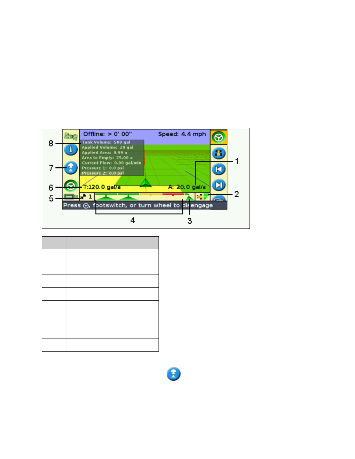
EZ−Boom 2010 System
EZ−Boom Features
When the EZ−Guide 500 system has firmware version 2.00 (or higher), it can be connected to the EZ−Boom 2010
automated application control system. This chapter describes features of the lightbar when an EZ−Boom 2010
system is connected.
When the EZ−Boom 2010 system is connected to the lightbar, the following features appear or become available:
ITEM DESCRIPTION
1 The actual current rate
2 Auto/manual switching indicator
3 Fence nozzle indicator
4 Boom section status indicators
5 Rate switch position
6 The intended target rate
7 EZ−Boom quick access icon
8 Information tab
Information tab − An additional information tab lists sprayer−specific information.•
EZ−Boom quick access icon − The icon enables you to access the most common EZ−Boom settings
•
more quickly. When you select the icon, the following screen appears:
93
Page 98

Additional status text items −•
If the EZ−Boom 2010 system is connected and the Rate switch is in either the Rate 1 or Rate 2
♦
position, the lightbar shows two additional status text items:
The intended target application rate (T:) is located at the bottom left of the main guidance
◊
screen.
The actual current application rate (A:) is located at the bottom right of the main
◊
guidance screen.
If the Rate switch is in the M (manual) position and the vehicle is moving, the status text items
♦
are:
The current flow rate (F:) is located at the bottom left of the main guidance screen.◊
The actual curent application rate (A:) is located at the bottom right of the main guidance
◊
screen.
If the Rate switch is in the M position and the vehicle is not moving, the status text displays N/A.♦
Rate switch position indicator − The lightbar shows the current position of the Rate switch: Rate 1, Rate
•
2, or Manual.
Boom section indicators − Indicators appear at the bottom of the main guidance screen. They change
•
color to show the current state of each boom section:
Green − The boom section is enabled and spraying.♦
Orange − The boom section is enabled but not currently spraying.♦
Red − The section is off (the switch is off).♦
If a fence nozzle is enabled, an indicator appears to the left or right of the boom section indicators. Fence
nozzle status is represented with the same colors as the boom sections.
Automatic/manual switching indicator − This indicator appears on the bottom right of the main guidance
•
screen and shows which switching mode the controller is in.
When the controller is in manual switching mode, the indicator is gray.♦
When the controller is in automatic switching mode, the indicator is in color.♦
To configure the EZ−Boom 2010 system for use with the lightbar, set the User Mode to Advanced and then select
Configuration / Application Control.
For more information, refer to the EZ−Boom 2010 System for the EZ−Guide 500 Lightbar Quick Reference Card.
Refilling the Tank
There are two ways to refill the tank:
94
Page 99

METHOD DESCRIPTION
Partial refill
Refill Resets the Current Volume value to the Capacity volume.
Increases the Current Volume value by the Partial Refill Quantity. This is useful if you add a
specific amount of solution to the tank each time you refill it.
EZ−Boom Flow Calibration
When you perform the EZ−Boom 2010 system flow calibration:
Enter the Flow Meter Calibration number:1.
Do one of the following:2.
If you know that the setting is correct, press the function button to save the calibration
♦
number that you entered and exit the menu. The system is now calibrated.
To complete a full calibration:♦
Enter the target rate, the speed, and the total number of nozzles.a.
Select Calibrate Now and then press . The Flow Calibration screen appears.b.
Read the information and then press . Flow begins.c.
Collect times samples from at least 3 nozzles separately for a total of 1 minute.d.
Press to stop the flow.e.
Calculate the volume that you collected per minute per value.f.
in the Measured Flow field, enter the volume that you calculated in the previous step.
g.
The system calculates the difference between the measured flow/nozzle and the averaged
flow/nozzle. The Calibration Complete screen appears. The flow meter calibration is
adjusted.
Manual Override
If you switch the Rate switch from Rate 1 or 2 to M (manual), you will get manual rate control but automated
boom switching will still be enabled. To obtain complete manual control of the EZ−Boom system (including
manual control of the sections) without having to go through the menus:
Stop the vehicle.1.
Turn the Master switch to Off.2.
Move the Rate switch to M (manual).3.
95
Page 100

Turn the Master switch back on.4.
The system is now in full manual mode. This can be useful for spraying corners or to continue spraying if you
lose GPS signal. To change back to automated mode, move the Rate switch to 1 or 2.
Swath Control Menu
Use the Swath Control menu to configure the following settings:
ITEM DESCRIPTION
Boom Control Enable or disable automated boom switching contol.
Controls the amount of overlap allowed before a boom section is switched off.
For example, if Allowable Overlap is set to:
* 99% − 99% of the boom section is allowed to overlap before it is switched off. This provides
the least amount of skip. Use this setting if you need to ensure complete coverage and using
Allowable
Overlap
Boom Valve
Latency
Intentional
Overlap
extra material does not matter.
* 50% − half of the boom section is allowed to overlap before it is switched off.
* 1% − 1% of the section width is allowed to overlap before it is switched off. This allows the
least overlap. Use this setting if you need to conserve the maximum amount of material.
Note: When going from sprayed to unsprayed areas the reverse is true. For example, with 1%
Allowable Overlap, the section width has to be in 99% uncovered area before it switches on.
Allows you to account for delays in the spray system. For correct operation, you must set this to
match the delay in your sprayer.
There are two settings, measured in seconds:
Valve On Latency − the time that it takes for the system to begin spraying after you turn it on.
Valve Off Latency − the time that it takes for the system to stop spraying after you turn it off.
Tip: To calculate the latency values, time your system with a stopwatch
Allows you to double−spray (buffer) a set distance to ensure complete coverage and avoid skips.
There are two settings, measured in distance:
On Overlap Distance − the overlap buffer when travelling into an area to be sprayed from an
already sprayed area. Spraying begins this distance before the area to be sprayed.
Off Overlap Distance − the overlap buffer when leaving the area just sprayed and entering an
already sprayed area. Spraying stops this distance outside the area just sprayed.
Spraying Pivots
If you are using the EZ−Boom 2010 system to spray a pivot, define the outer line of the pivot as your master line
and then work inwards. You cannot spray outside the pivot master line.
Spraying in reverse
Spraying in reverse is not supported. If you reverse the vehicle, the onscreen implement remains in place until the
vehicle appears to pass over it.
If you need to drive in reverse, set the EZ−Boom controller master switch to Off.
96
 Loading...