

Page 1
Ag Leader EZ-Guide
™
Quick Reference Card
A
CONFIGURING THE SYSTEM
CONFIGURATION OPTIONS
Step 1 Step 2 Step 3 Step 4 Step 5 Step 6
To configure
EZ-Guide, press the
following keys until
CONFIG appears:
To select an option,
press the following
key until the option is
displayed:
To display the value,
press:
T o ch ange the v alue,
press:
To accept the value,
press:
Return to step 2, or
press the following
keys until GUIDE is
displayed:
Option Default Values
WIDTH
60' Swath width – Set this to about 0.3 m (1 ft) less than your total boom width to ensure that there are no skips
between swaths.
LED MODE CHASE • CHASE – Chase the lights to stay online • PULL – Center the lights to stay online
SPACING
1' Distance represented by one LED.
HLNDWARN
0' Distance at which the Approach LED indicates your approach to the headland or end of swath line. It turns
orange.
XTE WARN
0' Distance off-swath at which the alarm sounds. Set to zero to disable the swath alarm.
BMOFFSET
0' • F<distance> – Boom in front of GPS antenna • R<distance> – Boom to rear of GPS antenna
LK AHEAD 1 SEC
Look ahead time in seconds. Predict your future guidance path by the number of seconds configured.
Increase this value for larger vehicles that take longer to turn.
• 0 to 8 mph – 1 second
• 8 to 15 mph – 2 seconds
• 15+ mph – 3 seconds
MOUNT DASH • DASH – Text aligned for upright dash mount • CEILING – Text aligned for ceiling mount
TEXT SWTH&XTE • SWTH&XTE – Swath number and cross-track error
•
SWTH&SPD – Swath number and current speed
•
HDG&SPD – Current heading and speed
•
DEMO – Sales demo mode
SNAPSWTH ON • ON – Lightbar automatically guides to nearest
swath
• OFF – Use the –/+ keys to change swath
DIFF SRC WAAS/EGN • WAAS\EGN – WAAS or EGNOS satellite
•
O-USA C – OmniSTAR U.S. Central satellite
•
O-S.AMER – OmniSTAR South American satellite
•
O-AFRICA – OmniSTAR African satellite
•
T-USA W – Thales U.S. Western satellite
•
T-USA E – Thales U.S. Eastern satellite
•
T-AFRICA – Thales African satellite
•
T-AUSTRL – Thales Australian satellite
•
O-USA W – OmniSTAR U.S. Western satellite
•
O-USA E – OmniST AR U.S. Eastern satellite
•
O-EUROPE – OmniSTAR European satellite
•
O-AUSTRL – OmniSTAR Australian satellite
•
T-USA C – Thales U.S. Central satellite
•
T-S.AMER – Thales South American satellite
•
T-EUROPE – Thales European satellite
DIFF GPS DIFFONLY • AUTO – Accept all positions including less
accurate non-differential positions
•
DIFFONLY – Accept only DGPS positions
•
AUTOWARN – Accept all positions, but warn if
differential corrections are lost
UNITS US • US – Feet, miles per hour, acres • METRIC – Meters, kilometers per hour, hectares
LANGUAGE ENGLISH • ENGLISH
• ESPANOL
• PORTUGES
DEFAULTS DEFAULTS
Return all configuration settings to factory defaults.
+
+
Ag Leader EZ-Guide
™
Quick Reference Card
A
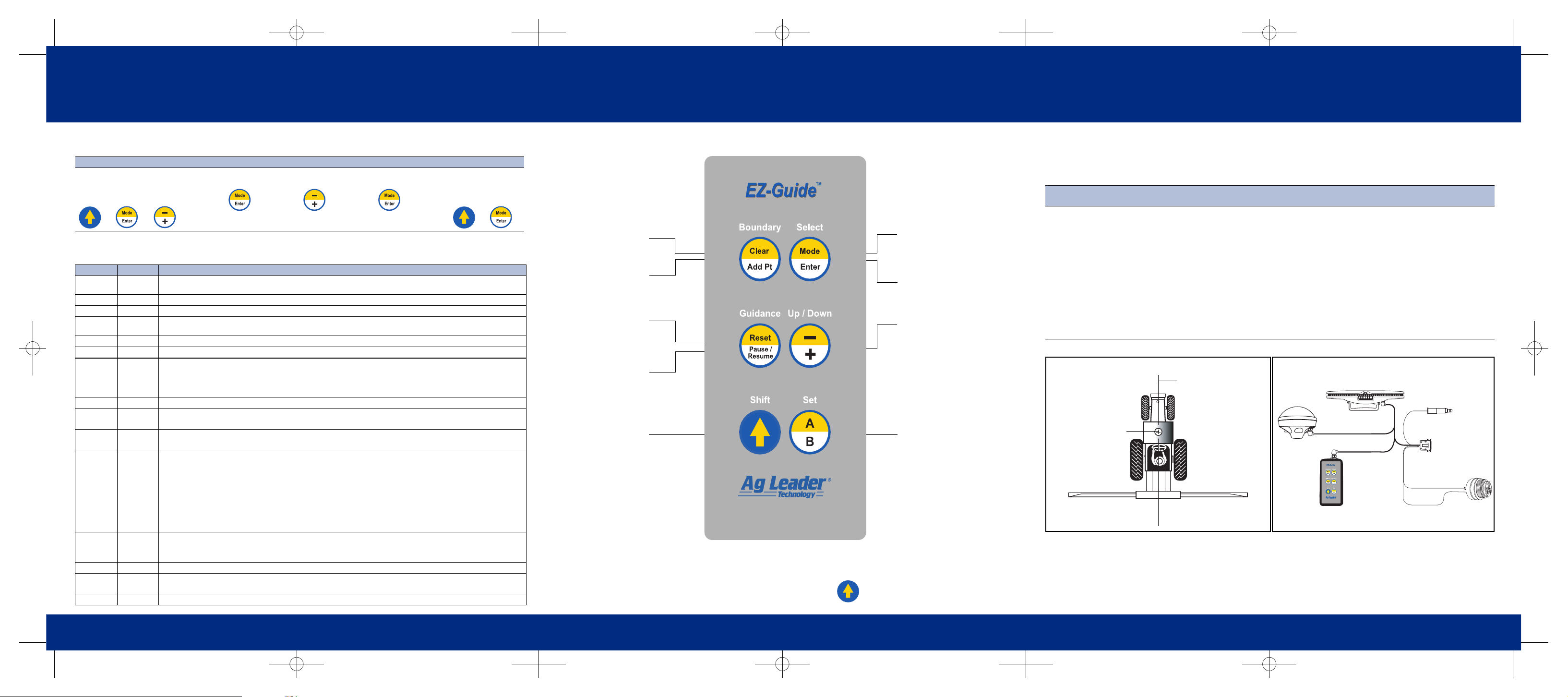
KEYPAD
LIGHTBAR DISPLAY BRIGHTNESS
To change the brightness level of the lightbar display, press and hold: .
© 2003. Trimble Navigation Limited. All rights reserved. EZ-Guide is a trademark of Trimble Navigation Limited licensed to Ag Leader Technology. Part Number 48651-40-ENG. Rev.A (January 2003).
MODE
Select Guidance, Area, or
Configuration modes.
CLEAR AREA
Clear all area points.
ADD AREA POINTS
Add an area point. The new
area is displayed briefly.
RESET GUIDANCE
Reset the guidance in
preparation for a new field.
ENTER
Select a configuration option
or accept a configuration
value.
SHIFT
• Press to access yellow
functions on other keys.
• Press and hold to change
the brightness of the
lightbar display.
• When editing configuration
values, press to toggle
between increasing and
decreasing the values.
–/+
• Increase or decrease
swath number if
SNAPSWTH is off.
• Scroll through
configuration options.
• Increase or decrease
configuration values.
PAUSE/RESUME
Pause or resume guidance.
SET A/SET B
Set the A or B point for
swath guidance.
Ag Leader EZ-Guide
™
Quick Reference Card
A
INSTALLATION
Step 1:
GPS antenna
Step 2:
Lightbar and remote keypad
Step 3:
Cables
Step 4:
Test your installation
a. Mount the antenna on the
highest part of the vehicle.
Ensure that there are no
obstructions in the way of
the GPS antenna.
b. Mount the antenna along the
boom centerline as shown
below.
Note – Ensure that the
vehicle with the GPS
antenna on top can safety fit
through the door of the
machine shed!
a. Attach the suction cup to the
lightbar. Mount the lightbar for
comfortable viewing inside
the cab.
Note – The lightbar can be
mounted upside down.To flip
the text, change the MOUNT
setting to CEILING.
b. Mount the remote keypad for
comfortable access.
a. Attach the cables as shown
below.
b. Place the cigarette lighter
plug into the vehicle’s
cigarette lighter adaptor.
c. Optionally, connect the
Sonalert alarm.
a. Drive outside and turn on the
unit. The lightbar display
should illuminate.
Note – GPS does not work
indoors.
b. Press –/+ to change the
swath widt h, then press Enter
to accept.
c. Wait for the SET A message
on the lightbar. EZ-Guide is
ready to use.
Mounting the antenna
Application boom
GPS antenna
Boom centerline
Lightbar
Attaching the cables
Remote
keypad
Sonalert
alarm
White +
Black –
To yield monitor
or computer
EZ-Guide cable
GPS4050
To power
Page 2
Ag Leader EZ-Guide
™
Quick Reference Card
A
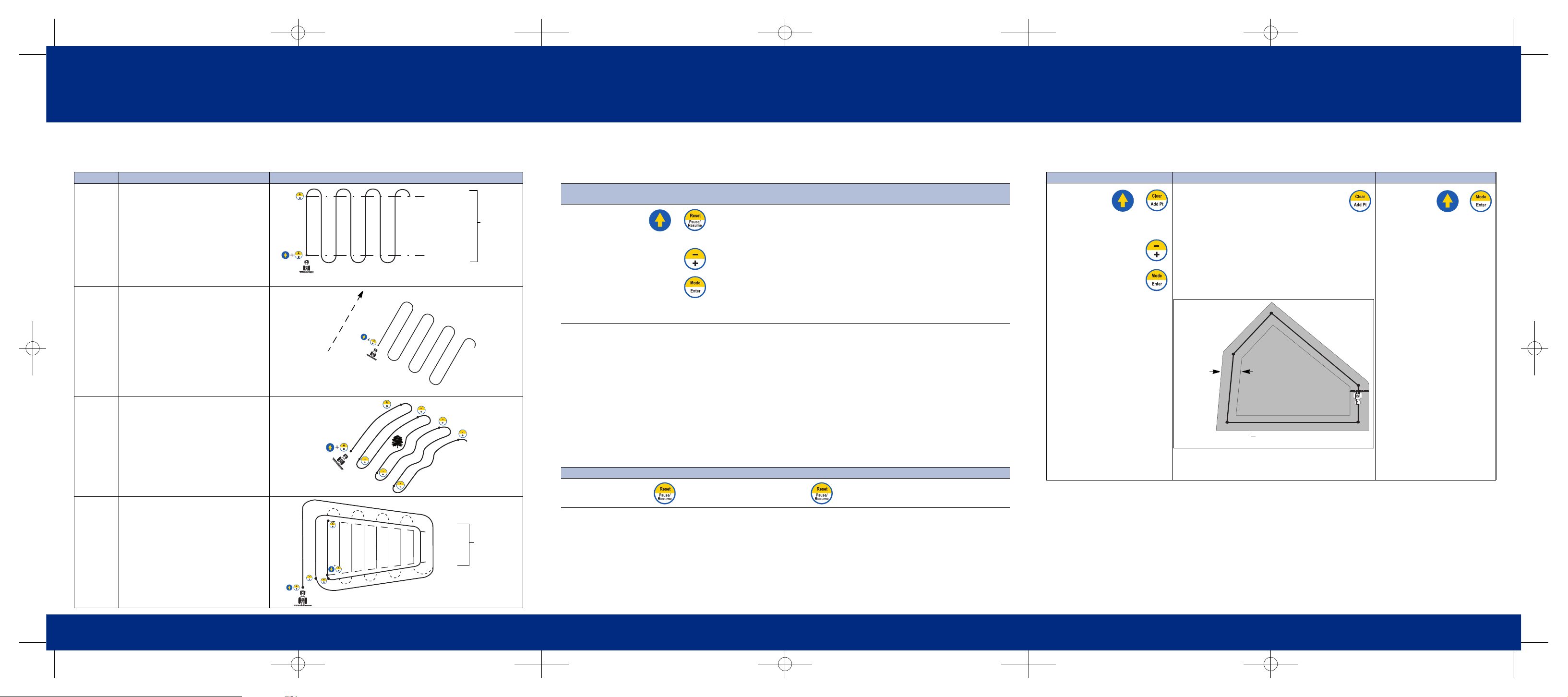
SWATH PATTERN OPTIONS
The following table lists the swath pattern options and describes the approach LED colors and operation.
Pattern Tips on using this pattern Diagram
NEW A-B
To set a straight guidance line, set new A
and B points.
If you have set area points, this area is
used for headland approach LED color.
This diagram assumes that snap to swath is ON.
NEW A+
Use A+ pattern for irregular gaps in your
field, or for adjacent parallel fields. Just
reset Point A to generate a new reference
line that is perfectly parallel to the last A-B
line.
With this pattern, if you have set area
points, this area is used for headland
approach LED color . If y ou d o not ha v e any
area points, then you do not get any
approach LED indication.
This option is only available if there is a
valid A-B Line still in memory.
This diagram assumes that snap to swath is ON.
NEWCURVE
To set a curved guidance line, set new A
and B points.
The approach LED does not indicate the
start and end of the curve swaths.
However , when you are approaching a turn,
end LEDs appear as a turn signal.
Snap to Swath is not available with the
Curve pattern. You must manually
increment the swath. Before beginning your
turn, you must press –/+.
NEWHLND
For straight parallel swaths inside the
headland, map at least one headland pass
around the outside of the field and then set
A and B points.
Before you can set the A and B points, you
must complete the headland.
When you approach the he adland, the
approach LED indicates your distance to
the end of the swath.
Note – EZ-Guide only calculates field area
based on area points, not headlands.
A
B
Green = Inside
Red = Outside
Red = Outside
Approach
LED color
A
Direction
of last
A-B line
A
B
Green
Red
Red
Approach
LED color
A
B
Ag Leader EZ-Guide
™
Quick Reference Card
A
GUIDANCE
To obtain guidance in a field, define a reference swath by mapping A and B points. The lightbar then provides
guidance at swath-width intervals. To get guidance:
Approach indication
The large, central LED indicates where you are in relation to the swath line:
• GREEN – inside the spray zone. Turn the boom on when the LED turns green.
• RED – outside the spray zone. Turn the boom off when the LED turns red.
For more information, see the diagrams in the SWATH PATTERN OPTIONS section on the previous page.
If the HLNDWARN value is configured to greater than 0, the approach LED turns ORANGE to indicate your
approach to the spray zone boundary (from either direction). Prepare to turn the boom on or off.
Pausing guidance
You can pause guidance, for example, to refill chemical tanks or refuel.
Step 1:
Clear guidance
Step 2:
Map the guidance line
Step 3:
Follow the lightbar
a. At the start of the
new field, clear old
guidance points by
pressing:
b. To select the desired pattern
option, press:
c. When the lightbar displays the
desired option, press:
• Diagrams in the SWATH PATTERN
OPTIONS section on the previous page
show which keys to press for each
pattern option.
a. Turn left or right for the next sw ath. If the
next swath is not automatically selected
or the wrong swath is selected, press
–/+.
b. Steer your vehicle so that you center
the green lights in the middle of the
lightbar and drive forward down the
swath.
Note – With a curve pattern, the lightbar LEDs and text only provide cross-track error (XTE) guidance parallel to the last swath.
When you get past the end of each swath, they display the distance to the end of the swath.
To pause guidance … To resume guidance …
While in mid-swath, press . Press again.
+
Ag Leader EZ-Guide
™
Quick Reference Card
A
CALCULATING ACREAGE
You can map area points to calculate acreage. Area points can be added in both Guidance mode and Area mode.
ALARMS
If the alarm is connected, it sounds at various times during a swathing operation to indicate that you are:
• entering or leaving the spray zone (as defined by the A-B end-zone, or by a defined headlands area)
• drifting too far off-swath (use the
XTE WARN option to configure this)
• returning to the current swath while guidance is paused
• losing differential corrections (use the
DIFF GPS option to configure this)
New Area Calculate Area View Area
1. To clear all
area points in
preparation
for a new field, at any time
press:
2. To toggle between
CONFIRM or
CANCEL, press:
3. When the desired
option is displayed,
press:
• To calculate the area of your field drive to each
corner of the field and press:
Each time the key is pressed, a new area value
is displayed. The area is calculated from the outside
end of the application boom.
Note – A minimum of three area points are required to
calculate the field area. The maximum number of area
points is 99.
The following diagram shows mapped area points and the
area calculated.
Tip – Acreage calculations take the current swath width
into account, so you should drive a half-swath in from the
field edge.
• To view the
field area at
any time,
press the following buttons until
the area is displayed:
+
Adjusted area is calculated
Actual swath
pass width
at the outside of the swath pass
+
 Loading...