

Page 1

Base Station
Hardware Manual
PN: 602-0024-02-C
Page 2

Legal Disclaimer
Note: Read and follow ALL instructions in this manual carefully before installing or operating the AutoSteer system.
Note: Take careful note of the safety information in the Safety Information section and throughout this manual.
The manufacturer disclaims any liability for damage or injury that results from failure to follow the instructions and warnings
set forth herein.
Technical Support
Contact your dealer for technical support.
Base Station Hardware Manual
Copyright © 2010. All Rights Reserved.
Page 3

Table of Contents
Chapter 1 Introduction ................................................................................................... 3
RTK and Base Station Basics . . . . . . . . . . . . . . . . . . . . . . . . . . . . . . . . . . . . . . . . . . . . . . . . . . 3
Repeatability . . . . . . . . . . . . . . . . . . . . . . . . . . . . . . . . . . . . . . . . . . . . . . . . . . . . . . . . . . . . . 4
Accurate Latitude and Longitude Positions . . . . . . . . . . . . . . . . . . . . . . . . . . . . . . . . . . . . . . 5
Maximizing Positioning Performance. . . . . . . . . . . . . . . . . . . . . . . . . . . . . . . . . . . . . . . . . . 7
Repeater Options . . . . . . . . . . . . . . . . . . . . . . . . . . . . . . . . . . . . . . . . . . . . . . . . . . . . . . . . . . 8
A5 Base Station Configurations . . . . . . . . . . . . . . . . . . . . . . . . . . . . . . . . . . . . . . . . . . . . . . . . 9
A5 Steer Mobile Base Station . . . . . . . . . . . . . . . . . . . . . . . . . . . . . . . . . . . . . . . . . . . . . . . . 9
A5 Repeater . . . . . . . . . . . . . . . . . . . . . . . . . . . . . . . . . . . . . . . . . . . . . . . . . . . . . . . . . . . . . . 9
AFLink Base Configurations. . . . . . . . . . . . . . . . . . . . . . . . . . . . . . . . . . . . . . . . . . . . . . . . . . . 9
AFLink Mobile Base Station. . . . . . . . . . . . . . . . . . . . . . . . . . . . . . . . . . . . . . . . . . . . . . . . . 9
AFLink Fixed Base Station . . . . . . . . . . . . . . . . . . . . . . . . . . . . . . . . . . . . . . . . . . . . . . . . . . 9
AFLink Repeater . . . . . . . . . . . . . . . . . . . . . . . . . . . . . . . . . . . . . . . . . . . . . . . . . . . . . . . . . 10
AFLink Radio Regulations . . . . . . . . . . . . . . . . . . . . . . . . . . . . . . . . . . . . . . . . . . . . . . . . . . . 10
FCC Regulations . . . . . . . . . . . . . . . . . . . . . . . . . . . . . . . . . . . . . . . . . . . . . . . . . . . . . . . . . . . 10
Important Regulatory Information. . . . . . . . . . . . . . . . . . . . . . . . . . . . . . . . . . . . . . . . . . . . . . 11
Nota Importante. . . . . . . . . . . . . . . . . . . . . . . . . . . . . . . . . . . . . . . . . . . . . . . . . . . . . . . . . . 11
Restricciones de uso . . . . . . . . . . . . . . . . . . . . . . . . . . . . . . . . . . . . . . . . . . . . . . . . . . . . . . 12
WICHTIGER HINWEIS. . . . . . . . . . . . . . . . . . . . . . . . . . . . . . . . . . . . . . . . . . . . . . . . . . . 13
BETRIEBSERLAUBNIS . . . . . . . . . . . . . . . . . . . . . . . . . . . . . . . . . . . . . . . . . . . . . . . . . . 13
Chapter 2 A5 Steer Base Station ................................................................................... 15
Determining a Location for the Mobile Base Station . . . . . . . . . . . . . . . . . . . . . . . . . . . . . . . 15
Hardware Components. . . . . . . . . . . . . . . . . . . . . . . . . . . . . . . . . . . . . . . . . . . . . . . . . . . . . . . 16
Back and Bottom Panel Hardware and Connectors. . . . . . . . . . . . . . . . . . . . . . . . . . . . . . . 17
Faceplate LEDs . . . . . . . . . . . . . . . . . . . . . . . . . . . . . . . . . . . . . . . . . . . . . . . . . . . . . . . . . . 17
Hardware Setup . . . . . . . . . . . . . . . . . . . . . . . . . . . . . . . . . . . . . . . . . . . . . . . . . . . . . . . . . . . . 19
Providing Power. . . . . . . . . . . . . . . . . . . . . . . . . . . . . . . . . . . . . . . . . . . . . . . . . . . . . . . . . . . . 22
Breaking Down the Base Station . . . . . . . . . . . . . . . . . . . . . . . . . . . . . . . . . . . . . . . . . . . . . . 24
Chapter 3 AFLink Mobile Base Station............................................................................ 27
Determine a Mobile Location . . . . . . . . . . . . . . . . . . . . . . . . . . . . . . . . . . . . . . . . . . . . . . . . . 28
Base Station Components . . . . . . . . . . . . . . . . . . . . . . . . . . . . . . . . . . . . . . . . . . . . . . . . . . . . 28
Radio Modem Kit Components . . . . . . . . . . . . . . . . . . . . . . . . . . . . . . . . . . . . . . . . . . . . . . . 30
Bottom Panel Hardware and Connectors. . . . . . . . . . . . . . . . . . . . . . . . . . . . . . . . . . . . . . . 30
Faceplate LEDs . . . . . . . . . . . . . . . . . . . . . . . . . . . . . . . . . . . . . . . . . . . . . . . . . . . . . . . . . . 31
Connecting the Components . . . . . . . . . . . . . . . . . . . . . . . . . . . . . . . . . . . . . . . . . . . . . . . . . . 32
Providing Power. . . . . . . . . . . . . . . . . . . . . . . . . . . . . . . . . . . . . . . . . . . . . . . . . . . . . . . . . . . . 34
Breaking Down the Base Station. . . . . . . . . . . . . . . . . . . . . . . . . . . . . . . . . . . . . . . . . . . . . . . 36
AFLink Software Configuration . . . . . . . . . . . . . . . . . . . . . . . . . . . . . . . . . . . . . . . . . . . . . . . 38
Chapter 4 AFLink Fixed Base Station.............................................................................. 39
Determining a Location for the AFLink Fixed Base Station. . . . . . . . . . . . . . . . . . . . . . . . . . 39
Hardware Component Spacing . . . . . . . . . . . . . . . . . . . . . . . . . . . . . . . . . . . . . . . . . . . . . . 40
AFLink Fixed Base Station Hardware Components . . . . . . . . . . . . . . . . . . . . . . . . . . . . . . . . 41
Base Station Kit. . . . . . . . . . . . . . . . . . . . . . . . . . . . . . . . . . . . . . . . . . . . . . . . . . . . . . . . . . 41
1
Page 4

Table of Contents
Radio Modem Kit Components. . . . . . . . . . . . . . . . . . . . . . . . . . . . . . . . . . . . . . . . . . . . . . 42
Base Station Receiver Faceplate LEDs and Connectors . . . . . . . . . . . . . . . . . . . . . . . . . . . 42
Hardware Installation. . . . . . . . . . . . . . . . . . . . . . . . . . . . . . . . . . . . . . . . . . . . . . . . . . . . . . . . 43
Mount GPS Antenna . . . . . . . . . . . . . . . . . . . . . . . . . . . . . . . . . . . . . . . . . . . . . . . . . . . . . . 43
Mount Radio Modem Antenna . . . . . . . . . . . . . . . . . . . . . . . . . . . . . . . . . . . . . . . . . . . . . . 46
Mount the Base Station Enclosure. . . . . . . . . . . . . . . . . . . . . . . . . . . . . . . . . . . . . . . . . . . . 48
Installing the AFLink Radio Modem. . . . . . . . . . . . . . . . . . . . . . . . . . . . . . . . . . . . . . . . . . 49
Connecting the GPS and Radio Modem Antennas . . . . . . . . . . . . . . . . . . . . . . . . . . . . . . . 53
Installing and Powering ON the Base Station . . . . . . . . . . . . . . . . . . . . . . . . . . . . . . . . . . . 54
Chapter 5 A5 and AFLink Repeaters............................................................................... 57
Introduction to A5 and AFLink Repeaters . . . . . . . . . . . . . . . . . . . . . . . . . . . . . . . . . . . . . . . 58
Repeater Concepts. . . . . . . . . . . . . . . . . . . . . . . . . . . . . . . . . . . . . . . . . . . . . . . . . . . . . . . . 58
Determining a Location for the Repeater . . . . . . . . . . . . . . . . . . . . . . . . . . . . . . . . . . . . . . . . 59
Using a Repeater . . . . . . . . . . . . . . . . . . . . . . . . . . . . . . . . . . . . . . . . . . . . . . . . . . . . . . . . . . . 60
Daisy Chaining . . . . . . . . . . . . . . . . . . . . . . . . . . . . . . . . . . . . . . . . . . . . . . . . . . . . . . . . . . 60
Multiple Repeater Setup . . . . . . . . . . . . . . . . . . . . . . . . . . . . . . . . . . . . . . . . . . . . . . . . . . . 62
Incorrect Repeater Usage. . . . . . . . . . . . . . . . . . . . . . . . . . . . . . . . . . . . . . . . . . . . . . . . . . . . . 63
Hardware Components . . . . . . . . . . . . . . . . . . . . . . . . . . . . . . . . . . . . . . . . . . . . . . . . . . . . . . 64
A5 Repeater Components . . . . . . . . . . . . . . . . . . . . . . . . . . . . . . . . . . . . . . . . . . . . . . . . . . 64
AFLink Repeater Components . . . . . . . . . . . . . . . . . . . . . . . . . . . . . . . . . . . . . . . . . . . . . . 65
Assembling the Repeater . . . . . . . . . . . . . . . . . . . . . . . . . . . . . . . . . . . . . . . . . . . . . . . . . . . . . 66
Mounting Options . . . . . . . . . . . . . . . . . . . . . . . . . . . . . . . . . . . . . . . . . . . . . . . . . . . . . . . . . . 67
Tripod Mounting . . . . . . . . . . . . . . . . . . . . . . . . . . . . . . . . . . . . . . . . . . . . . . . . . . . . . . . . . 67
Using a Pole Mount. . . . . . . . . . . . . . . . . . . . . . . . . . . . . . . . . . . . . . . . . . . . . . . . . . . . . . . 68
Mounting in a Permanent Location . . . . . . . . . . . . . . . . . . . . . . . . . . . . . . . . . . . . . . . . . . . 69
Providing Power. . . . . . . . . . . . . . . . . . . . . . . . . . . . . . . . . . . . . . . . . . . . . . . . . . . . . . . . . . . . 69
Breaking Down the Repeater. . . . . . . . . . . . . . . . . . . . . . . . . . . . . . . . . . . . . . . . . . . . . . . . . . 70
2 Base Station
Page 5

Introduction
The information for this Introduction chapter is contained in the following sections:
• RTK and Base Station Basics
• Repeatability
• Accurate Latitude and Longitude Positions
• Maximizing Positioning Performance
• Repeater Options
• A5 Base Station Configurations
• A5 Steer Mobile Base Station
• A5 Repeater
• AFLink Base Configurations
• AFLink Mobile Base Station
• AFLink Fixed Base Station
• AFLink Repeater
• AFLink Radio Regulations
• FCC Regulations
• Important Regulatory Information
• Nota Importante
• Restricciones de uso
• WICHTIGER HINWEIS
• BETRIEBSERLAUBNIS
1
RTK and Base Station Basics
Real-time kinematic, or RTK, refers to a GPS positioning system comprised of two GPS Receivers with a data link between
them. One GPS Receiver is the on Base Station, which must remain stationary. The other GPS Receiver is on the vehicle,
which can move around. The purpose of the Base Station is to calculate position corrections and transmit them to the vehicle.
The vehicle uses the position corrections to determine its position (and Autosteer) with sub-inch accuracy. It is important that
the Base Station does not move during operation, since the vehicle's position is measured relative to the Base Station’s fixed
position.
• If you want to continue or repeat a previous job, the Base Station GPS Antenna must be returned to the exact location as
when the job was created. For more information, see Repeatability on page 4.
• If you need accurate latitude and longitude positions for your vehicle (for example to use mapping functions of the User
Display and/or 3rd party software for boundary creation or vari able rate applications), the Base Station’s GPS Antenna
latitude and longitude must be known. For more information, see Accurate Latitude and Longitude Positions on page 5.
• If repeatability is not needed for your operation, the Base Station's GPS Antenna does not need to be returned to an exact
location. In this case, using the Tripod provided with the Mobile Base Station provides the most flexibility and/or
portability.
Hardware Installation Manual 3
Page 6

Repeatability
Repeatability
Repeatability is the ability to return your vehicle to a previously established field and repeat or continue a saved job (Autosteer
over the same guidance paths), whether it is the next day or the next season. For example, if you want to install drip tape, not
only do you want to put it in the ground straight, you want the ability to return to that field and make beds directly over the top
of the drip tape. The same is true for cultivating or harvesting. If you create a job and plant a crop, you want to be confident
when you return to that field and job that you can pull the cultivator over the plants and get the blades as close as possible
without destroying them.
To achieve repeatability, the Base Station GPS Antenna must be in the exact same position as it was when the job was
originally created. The best ways to achieve repeatability are to either (1) use a Permanent Base Station configuration, or (2)
create a semi-permanent mount for your Mobile Base Station. See Marking the Base Station's GPS Antenna Location on
page 4.
Note: Correctly following the steps needed for repeatability does not mean that the vehicle will have an accurate latitude
and longitude position. For more information, see Accurate Latitude and Longitude Positions on page 5.
Marking the Base Station's GPS Antenna Location
To take advantage of repeatability's many benefits, AutoSteer system owners have established several methods of positioning
the Base Station's GPS Antenna at the exact same position every time they return to the same location. The GPS Antenna must
also be mounted on a sturdy structure where the GPS Antenna does not move at all. Mounting the GPS Antenna on radio
towers or elevator legs are generally poor places to mount the GPS Antenna as they may not be sturdy enough in windy
conditions unless they are guyed stiffly - any movement of the Base Station GPS Antenna is transferred to the vehicle. For best
performance, the GPS Antenna should be mounted closer to the ground on a sturdy structure.
Some examples of how AutoSteer system owners have ensured repeatability are as follows:
1. Find a location near the field that is not disturbed by traffic and is easily accessible. Embed a steel pole in concrete at the
selected location. Fit a Quick-Release Connector (200-0405-01) on top of the pole, which is used to mount the Base
Station's GPS Antenna. This method enables the user to create a permanent mounting point that makes it easy to break
down and move the Base Station to another location if necessary. Placing the steel pole in a fence row is a good practice as
it places it out of the way.
2. Similar to the previous example, a mounting pole can be firmly attached to an existing fence post. The GPS Antenna can
then be attached to the mounting pole.
3. Use a plumb-bob attached to the Tripod to locate its center-point at ground level. The location on the ground can then be
permanently marked with a stake or concrete pad. When returning to the location, make sure the Tripod is properly
centered over the mark. If consistent elevations are necessary, ensure that the Tripod at the exact height when returning to
the site.
Note: Returning the GPS Antenna to the exact elevation is not required for steering repeatability, only leveling.
4. The other option is to use a permanently mounted Base Station configuration and rigidly attach the GPS Antenna to the top
of a building or tower. When mounted, the GPS Antenna and the structure holding the GPS Antenna cannot move. The
4 AutoSteer System
Page 7

Accurate Latitude and Longitude Positions
advantage of this method is that it provides a large RTK coverage area without the need to move the Base Station
components once they have been installed.
Accurate Latitude and Longitude Positions
Mapping functions of the User Display and/or 3rd party software for boundary creation or variable rate applications require an
accurate latitude and longitude position for the vehicle. The latitude and longitude of the vehicle is calculated by its relative
distance to the latitude and longitude of the Base Station GPS Antenna. Therefore, the accuracy of the latitude and longitude of
the vehicle is entirely dependant on the accuracy of the latitude and longitude the Base Station. Accurate Base Station position
is accomplished by either “surveying in” or by manually entering a known position as discussed in the following sections.
Note: If accurate vehicle latitude and longitude is not needed, an RTK system still provides sub-inch accurate positioning.
Additionally, repeatability is independent of accurate latitude and longitude. In other words, even without an accurate
latitude and longitude, the vehicle will still be able to steer with sub-inch accuracy and repeat saved jobs.
Base Station Surveying for Accurate Latitude and Longitude
Note: If a job does not require an accurate latitude and longitude for example, to use with 3rd party software for mapping
and variable rate applications, it is not necessary to take the time to let the Base Station survey in.
The Base Station is designed to automatically survey its position over a continuous 24 hour period to an accuracy of 4 inches
(10 cm). Once the Base Station is powered on, it will begin to average its position. After it has been running for at least 24
hours, the system will calculate its position and store it for future use. If the Base Station antenna is moved to another position,
the survey process starts over and the new position will be saved. The Base Station can store up to 16 different locations. When
the Base Station is powered up, it will first check to see if it is near any of the stored locations in its memory. If it is, it will
automatically use that stored location as the latitude and longitude it uses to calculate the vehicle's latitude and longitude.
Initial Survey Procedure
Follow this procedure when setting up a new job (at a new location) that requires accurate vehicle latitude and longitude.
1. Choose a location and mount the Base Station according to the guidelines in Repeatability on page 4 and Maximizing
Positioning Performance on page 7. Also, see the appropriate chapter for your Base Station configuration for detailed
hardware setup instructions.
2. Power ON the Base Station, and plan to leave it on for at least 24 hours.
3. Inspect the faceplate LEDs. See the appropriate chapter for your Base Station configuration for additional information on
the LEDs.
• The PWR LED should be on steady, indicating constant power supply.
• The ST LED will flash indicating the channel number of the Base Station (should be last 3 digits of the serial number).
• Once the Base Station begins to receive satellite signals, the NSV LED will blink once per satellite received separated by
a short pause between groups.
• Once sufficient satellite data has been received to begin position averaging, the ST LED will begin to blink once per
second.
Hardware Installation Manual 5
Page 8

Accurate Latitude and Longitude Positions
• The ST LED will continue to blink once per second until it has averaged 24 hours of position data. Note that if position
data drops below an acceptable range, the data will not be included in the average and the overall time will be increased
proportionally.
4. Once the Base Station has received and averaged the position data for 24 hours (36400 seconds) the location will be saved
within the Base Station's data base and the ST LED will stop blinking and be on solid . A soli d ST LED indicates that the
Base Station is operating from a saved and validated location.
5. Work can now begin at this site with a latitude and longitude accuracy of +/- 10cm.
6. If power is lost or removed the Base S tation will rememb er its last known position. When power is restored, during the first
60 second of position data, it will attempt to validate that it has not moved from that location . During which time it will
output its best known position. If it senses that it is at the same location (within 4 meters) it will vali date that position and
the ST LED will stop blinking and turn on solid, and then it will output the stored position providing the user with +/10cm accuracy.
Procedure for Additional Surveys
Follow this procedure when at least one survey at a different location has been successfully completed, and you are setting up
a new job (at a new location) that requires accurate vehicle latitude and longitude.
1. Choose a location and mount the Base Station according to the guidelines in Repeatability on page 4 and Maximizing
Positioning Performance on page 7 . Also, see the appropriate chapter for your Base Station configuration for detailed
hardware setup instructions. This location should be at least 35 feet from any saved/previously surveyed locations.
2. Follow steps 2-5 of Initial Survey Procedure on page 5.
Note: The Base Station has the capacity to store up to 16 separate locations. If it is moved to a 17th location, it will
delete the oldest stored location and add the new one when the survey is complete.
Procedure for Powering Up at a Surveyed Location
Follow this procedure when repeating or continuing a job (or if power is lost) at a saved/surveyed location.
1. If the Base Station has moved, place the Base Station in precisely the same location as the previously surveyed location.
See Repeatability on page 4 for information on correct Base Station positioning.
2. Power ON the Base Station.
• The Base Station will attempt to validate that it has not moved from its last known location. This could take approximately
5 minutes. During this time it will output its best known position. If it senses that it is at the same location (within 4 meters)
it will validate that position, and the ST LED will stop blinking and turn on solid. It will then output the stored position
with +/- 10cm accuracy.
• If the Base Station determines that it is not within 4 meters of its last known position, it will search the stored locations to
find a location within 4 meters of the current position. Upon finding the previously stored location the Base Station will
deselect the previous last known position and select, activate and validate the stored position. When a known position is
found and validated, the ST LED will stop blinking and turn on solid. It will then output the stored position providing the
user with +/- 10cm accuracy.
• If the Base Station is unable to find a known location, it will begin a new survey. When complete, the ST LED will stop
blinking and be on solid.
3. Work can now begin at this site with a latitude and longitude accuracy of +/- 10cm.
6 AutoSteer System
Page 9

Maximizing Positioning Performance
Using a Known Position for Accurate Latitude and Longitude
A known Base Station location can also be entered manually by your dealer using the Base Station Configuration tool, the
proper service cables, and a laptop. This option should be used only if the exact position is known. If an incorrect position i s
entered into the Base Station, the latitude and longitudes of the vehicle uses for display functions and 3rd party software will
be shifted. However, the system can still provide sub-inch and repeatable guidance so long as the Base Station GPS Antenna
has not been moved. See your dealer for help with entering a known position.
Maximizing Positioning Performance
This section provides information for ensuring optimal positioning performance. These guidelines apply to any job regardless
of the need to repeat the job or achieve an accurate latitude and longitude. When planning a location for your Base Station on
any job, take all of the following into account:
Effective Ranges
The effective ranges of Base Stations providing sub-inch accuracy are as follows:
Note: The ranges are based on clear line of site between the rover antenna and the Base Station transmitter. Without a
clear line of site, expected distances will be reduced.
• A5 Steer Base Station (mobile) with flexible rubber antenna - 1 to 2 miles (1.6 to 3.2 km).
• A5 Steer Base Station (mobile) with a pole antenna elevated at least 10 feet (3 meter) - 3 to 4 miles (4.8 to 6.4 km).
Other Considerations
• Communication signals between the Base Station and the vehicle require line-of-sight. Identify and eliminate any obstacles
or issues that could block line-of-site from the Base Station to the entire work area. Obstacles such as trees, buildings,
vehicles, and levees can create areas where the vehicle cannot receive the signals from the Base Station and prevent the
system from functioning.
• The Base Station GPS Antenna must have an unobstructed view of the sky. Do not mount the GPS Antenna next to
buildings, bins, trees, radio towers, grain legs, etc. Any obstruction reduces the accuracy and performance of the entire
system. Do not park any vehicles next to the Base Station, especially with the hood up.
• The Base Station GPS Antenna must be level for accurate performance.
• The Base Station GPS Antenna must be solidly mounted to minimize movement caused by wind or vibrations. Minimize
any type of foot or vehicle traffic within a 20 foot (6.0 meter) radius of the Base Station.
• If the GPS Antenna must be mounted in a place with obstacles, position the GPS Antenna as far away as possible without
exceeding the maximum cable length.
• As a general rule, keep any obstacle below a 15° angle from the GPS Antenna.
• Raise the Radio Modem Antenna as high as possible. The higher the Radio Modem Antenna, the farther the signal can
travel by avoiding potential obstacles.
• The Radio Modem Antenna position is not important for RTK performance. The Radio Modem Antenna does not need to
be placed in the exact same position when setting up a Base Station. Also, it does not have to be as firmly attached as the
GPS Antenna. Avoid excessive movement, but it can sway slightly so it is possible to mount this antenna on the top of radio
towers or grain legs.
• Higher-powered antennas can be used to extend the Base Stat ion signal range. However, do not use an antenna that exceeds
local radio transmission regulations.
Hardware Installation Manual 7
Page 10

Repeater Options
Repeater Options
An RTK system works only when the radio link between the Base Station and rovers are line of site. The radio waves
transmitted from the Base Station can be blocked by obstacles such as trees, hills, buildings, etc. In order to get a radio signal
around these obstacles, a repeater can be used to receive and then retransmit an RTK signal. The repeater is placed at a point
where it is in view of both the Base Station and the mobile receiver. The repeater then passes the RTK signal around the
obstacle to the rover and allows RTK guidance. The accuracy of the RTK system is still based on the location differences
between the Base Station GPS Antenna and the rover, so sub-inch accuracy cannot be extended past the 6 mile (9.7 km) limit.
There are two versions of the repeater:
• A5 Repeater
• AFLink Repeater
The A5 Repeater can be used with any A5 Base Station. The AFLink Repeater can only be used with the AFLink Base Station
models. The difference between the two is the radio. Though both models of repeaters serve the same purpose, the type of
radio that is installed determines which features are available and how it works in the system. For more information on
Repeaters, see A5 and AFLink Repeaters on page 57.
8 AutoSteer System
Page 11

A5 Base Station Configurations
A5 Base Station Configurations
The RTK Base Station is available in the configurations described in the this section. Additionally, a repeater to route signals
around obstacles is available.
A5 Steer Mobile Base Station
The A5 Steer Mobile Base Station is designed for use with the AutoSteer module.
• Part number: 130-0033-01 or 4100651-1 (AL)
A5 Repeater
The A5 Repeater is an external radio modem and antenna used to retransmit RTK signals around obstacles. This version will
work with all A5 Base Station models using a 900MHz radio. The radio channel must be set the same on the repeater as it is on
the Base Station and rover to work.
• Part number: 130-0035-016.
AFLink Base Configurations
The AFLink family of Base Stations functions similarly to standard A5 AutoSteer system Base Stations. The primary
difference is that AFLink bases have radios which broadcast on 400MHz licensed frequencies. Customers choose AFLink
radios to comply with regional broadcast regulations (example: FCC licenses required for US operation) or for better radio
performance over tree lines or hilly terrain.
Note: The AutoSteer system radio on the vehicle must be matched to the Base Station radio.
The AFLink base is available in two different configurations, one fixed and one mobile. Each option is detailed in the
following sub-sections:
AFLink Mobile Base Station
The AFLink Mobile Base Station is designed for quick deployment in the field.
• Part number: 130-0042-01 (Mobile Base Kit without Radio)
The AFLink Mobile Base Station must be ordered with an AFLink radio that uses the correct frequency for the geographical
location in which it is used. See your dealer for additional information.
AFLink Fixed Base Station
The AFLink Fixed Base Station is designed to be permanently-mounted (on a barn or other structure) and provide coverage for
a fixed area or farm.
Hardware Installation Manual 9
Page 12

AFLink Repeater
AFLink Repeater
This is an external AFLink radio modem and antenna used to retransmit RTK signals around obstacles. This version will work
with AFLink Base Station models. The AFLink Repeater must match the frequency of the Base Station and rover.
AFLink Radio Regulations
The standard A5 Base Stations do not require a license to operate as they operate on the public 900MHz frequency. The
AFLink radios broadcast on a regulated frequency. If using an AFLink radio, the operator is required to follow additional
regulations in order to operate the radios legally. The regulations and laws vary by country and location. Before operating an
AFLink radio, obtain a copy of the local laws and ensure they have been followed.
Modifying or tampering with the device's internal components can cause a malfunction and might invalidate its warranty and
void your authorization to operate it. If your system is not performing satisfactorily, contact your local dealer for assistance.
This product uses one or more radio devices that must be licensed in order to be operated legally. It is the end user's
responsibility to apply for, hold and renew applicable licenses for these devices.
Note: Do not operate this system until legal authorization has been obtained. Severe fines can be levied for unlicensed
systems. Any fines are the responsibility of the owner.
FCC Regulations
When operating in the United States, FCC licenses are required for AFLink radios.
This device is intended for use in the operation of commercial activities, educational, philanthropic, or ecclesiastical
institutions, hospitals, clinics, or medical associations.
The Federal Communications Commission (FCC) requires you to have a license before you operate this device. Unless you are
already licensed to operate on one of the preset frequencies, you must apply for a frequency through the PCIA (Personal
Communication Industry Association), a non-profit organization that assigns frequencies nationwide to help prevent conflicts
between different businesses using devices in the same area. For more information about getting a license, contact the PCIA at
800-759-0300, extension 3068 (in Virginia 703-739-0300, extension 3068).
For other questions concerning the license application, contact the FCC at 717-337-1212, or write:
FCC
P.O. Box 1040
Gettysburg, PA 17325
For the latest FCC application form and instructions, call the FCC's fax-on demand service at 1-202-418-0177 from a fax
machine and request one or more of the following documents:
All forms and instructions 000600
If you do not have a fax machine, you can call the Government Forms Distribution Center at 1-800-418 -FORM and request
that the form and instructions be mailed to you.
FCC Part 90 Rules
10 AutoSteer System
Page 13

Important Regulatory Information
You must be familiar with Part 90 of FCC Rules before you operate your device. The operation instructions in this manual
conform to Part 90, but do not cover all items in Part 90. Form 600 instructions only 006001 Main Form 600 only 006002
Form 600 schedules only 006003
8 FCC Regulations
Overall, Part 90 states that:
• You must have a valid license before you use the device.
• As licensee, you are responsible for the proper operation of all devices operating under your license authority.
• You can let unlicensed persons operate your transmitter, as long as you take precautions to prevent unauthorized
transmissions.
• Y ou must use this device only for the commercial use of your business and only when other commercial channels are either
not available or not practical.
• You must always yield the operating frequency to communications that involve the safety of life or property.
• You must take reasonable precautions to prevent harmful interference to other services operating on the same frequency.
• You must keep a written record of any maintenance or modification made to the device, and you must make this record
available for inspection upon demand by the FCC.
Violating any of the provisions of Part 90 can result in fines and/or confiscation of equipment.
Your equipment might cause TV or radio interference even when it is operating properly. To eliminate interference, you can
try one or more of the following corrective measures:
• Reorient or relocate the receiving antenna.
• Increase the distance between the equipment and the radio or TV.
• Use outlets on different electrical circuits for the equipment and the radio or TV.
Consult your local dealer if the problem still exists. You must use shielded interface cables with this equipment.
Additional FCC Regulations
The Business Service is under the jurisdiction of the Federal Communications Commission (FCC). Any adjustments or
alterations that would alter the FCC Regulations performance of the device so it no longer meets the original FCC type
acceptance or would change the frequency determining method are strictly prohibited. Replacement or substitution of crystals,
transistors, integrated circuits, regulator diodes, or any other component that is of a unique nature with components other than
those recommended can violate the technical regulations of the FCC Rules or violate type acceptance requirement of the rules.
Before you operate the device, you must obtain your license. It is illegal to transmit without the appropriate license, which you
can get by submitting a completed FCC Form 600 to the FCC (or through the PCIA). Furthermore, you are required to
understand Part 90 of the Look at Your Devices FCC Rules prior to operating your device. It is the user's responsibility to see
that this unit is operating at all times in accordance with the FCC Rules.
Important Regulatory Information
Nota Importante
Todos los derechos sobre este manual son propiedad exclusiva de Novariant OY (Novariant de ahora en adelante). Todos los
derechos están reservados. La reproducción de este manual sin la autorización por escrito del propietario de los derechos, ya
sea por impresión, fotocopia, grabación o por cualquier otro medio, o la traducción total o parcial del manual a cualquier
idioma incluyendo todos los lenguajes de programación que usan cualquier manual eléctrico, mecánico, magnético, óptico, u
otros métodos está prohibida.
Hardware Installation Manual 11
Page 14

Restricciones de uso
Novariant se reserva el derecho de cambiar las especificaciones técnicas o funciones de sus productos, de cesar en la
producción o soporte de cualquiera de sus productos sin previo aviso por escrito e insta a sus clientes a asegurar, que la
información a su disposición es válida.
El software y programas de Novariant se entregan tal cual. El fabricante no ofrece ningún tipo de garantía de venta o
relacionadas con la aplicabilidad de una cierta aplicación. El fabricante o empresa técnica de d esarrollo de un programa, no se
responsabiliza en ningún caso, de posibles daños causados por el uso del programa. Los nombres de los programas así como
sus copyrights son de única propiedad de Novariant. Cualquier cesión, concesión a una tercera parte, leasing, renting,
transporte, copia, edición, traducción, cambio a cualquier otro lenguaje de programación o ingeniería inversa está prohibida
sin el consentimiento escrito de Novariant.
LOS PRODUCTOS DE NOVARIANT NO HAN SIDO DISEÑADOS, INVENTADOS NI INSPECCIONADOS PARA
USARSE EN MEDIOS RELACIONADOS CON EL SOPORTE VITAL O FUNCIONES RELACIONADAS AL SISTEMA,
NI COMO PARTE DE CUALQUIER OTRO SISTEMA CRÍTICO Y NO OFRECEN GARANTÍA DE
FUNCIONAMIENTO SI SON USADOS EN CUALQUIER DE LAS APLICACIONES MENCIONADA S.
Salo, FINLANDIA 2000 Los radio módems SATELLINE-3AS (d) han sido diseñados para operar en rangos de frecuencia, su
uso exacto difiere de una región / país a otra/o. El usuario de un radio módem debe tener cuidado de que dicho aparato no
opere sin el permiso de las autoridades locales en salvo en esas frecuencias reservadas específicamente para uso sin permiso
específico. Por esta razón, la marca se encuentra unida al radio módem.
Restricciones de uso
El modelo SATELLINE-3AS (d) 869 MHz está diseñado para operar en la banda de frecuencia 869.400-869.650MHz sin
necesidad de permiso, según las normas CEPT/ERC/REC 70-03. Esta recomendación ha sido emitida por el Comité Europeo
de Radiocomunicaciones (ERC) bajo el CEPT. El ciclo de transmisión /recepción de la unidad individual está limitada a 10%
en esta banda, y el período singular de transmisión no debe exceder los 36s. Además, la potencia máxima irradiada permitida
es de 500 mWerb.
AVISO! Los usuarios de SATELLINE-3AS(d) en Norte-América deben saber que debido a la localiz aci ón de la banda de
frecuencia 406.0-406.1 MHz para uso exclusivo del Gobierno, el uso del radio módem en esta banda de frecuencia sin
permiso, está estrictamente prohibido.
NOTA PARA ESPAÑA SEGÚN RD 1890/2000
CE0341
Este equipo requiere licencia administrativa. Dirección en España:
RADIOCOM MULTICOMUNICACIONES, S.A. C/ISABEL COLBRAND 10. ED. ALFA III-NAVE 93 28050 MADRID
GARANTIA E INSTRUCCIONES DE SEGURIDAD
Lea estas instrucciones de seguridad cuidadosamente antes de usar el producto:
• La garantía será nula, si el producto se utiliza en cualquiera de las formas que son contrarias a las instrucciones dadas en
este manual, o si la caja del radio módem ha sido abierta o manipulada.
• El radio módem debe utilizarse solo en frecuencias asignadas por las autoridades locales y sin exceder la potencia máxima
permitida. Novariant no es responsable, si los productos fabricados son usados de forma ilegal.
• Los aparatos mencionados en este manual deben utilizarse según las instrucciones descritas en este manual. Se garantiza
las operaciones impecables y de seguridad de los aparatos solo si el transporte, almacenaje, operación y manipulación de
los aparatos es correcto. Esto también es aplicable al mantenimiento de los productos.
12 AutoSteer System
Page 15

WICHTIGER HINWEIS
• Para prevenir el daño tanto del radio módem como de cualquier terminal debe siempre estar apagado (OFF) antes de
conectar o desconectar el cable de conexión de serie. El usuario debería asegurarse de que los diferentes aparatos utilizados
tengan el mismo potencial de tierra. Antes de conectar cualquier cable de potencia el voltaje del suministro debe ser
comprobado.
WICHTIGER HINWEIS
Alle Rechte an diesem Handbuch gehören allein Novariant OY (in diesem Handbuch als Novariant bezeichnet). All Rechte
sind vorbehalten. Vervielfältigung dieses Handbuches (ohne die schriftliche Zustimmung des Eigentümers) durch Druck,
Kopie, Aufzeichnung oder andere Methoden, oder die volle oder teilweise Übersetzung des Handbuches in eine andere
Sprache einschließlich Programmiersprachen, mittels elektrischer, mechanischer, magnetischer, optischer, manueller oder
anderer Methoden oder Geräte ist verboten.
Novariant behält sich das Recht vor, technische Spezifikationen oder Funktionen der eigenen Produkte zu ändern, die
Herstellung dieser Produkte oder den Support für eines dieser Produkte einzustellen, ohne dass es einer schriftlichen
Ankündigung oder Mitteilung der Kunden bedarf. Der Kunde hat sicherzustellen, dass die ihm zur Verfügung stehenden
Informationen gültig sind.
Novariant Software und Programme werden geliefert, wie sie sind (”as is”). Der Hersteller übernimmt keinerlei
Gewährleistung und Garantie für die Funktionalität und Anwendbarkeit einer bestimmten Applikation. Der Hersteller oder
Entwickler eines Programms übernimmt in keinem Fall die V era ntwortung für irgendwelche Schäden, die durch den Gebrauch
des Programms entstanden sind. Die Namen der Programme und die copyrights für diese entsprechenden Programme sind das
alleinige Eigentum von Novariant. Jede Übertragung, Lizensierung für einen Dritten, Leasing, Vermietung, Versendung, sowie
das Kopieren, Bearbeiten, Übersetzen, Verändern in eine andere Programmiersprache oder “Reverse Engineering” für
jeglichen Gebrauch ist ohne die schriftliche Zustimmung von Novariant verboten.
NOVARIANT PRODUKTE WURDEN WEDER GEBAUT NOCH SIND SIE FÜR DEN GEBRAUCH IN EINER
LEBENSUNTERSTÜTZENDEN ODER LEBENSERHALTENDEN EINHEIT ODER EINEM SOLCHEN SYSTEM ODER
ALS TEIL EINES ANDEREN KRITISCHEN SYSTEMS BESTIMMT UND ES WIRD KEINE FUNKTIONSGARANTIE
ÜBERNOMMEN, WENN SIE IN EINEM SOLCHEN SYSTEM EINGESETZT WERDEN.
Salo, FINLAND 2002
BETRIEBSERLAUBNIS
SATELLINE-3AS(d) Funkmodems wurden für den Betrieb in Frequenzbereichen entwickelt, die je nach Region und/oder
Land unterschiedlich sein können. Der Anwender hat dafür Sorge zu tragen, dass das Funkmodem ohne die Genehmigung der
lokalen Behörden nur auf den speziell für den genehmigungsfreien Betrieb reservierten und dafür vorgesehenen Frequenzen
betrieben wird. Aus diesem Grunde ist das Achtungzeichen am Funkmodem angebracht.
Das Modell SATELLINE-3AS(d) 869 ist entwickelt für den Betrieb im lizenzfreien Frequenzband von 869.400 – 869.650
MHz entsprechend der Richtlinie CEPT/ERC/REC 70-03. Diese Richtlinie wurde von dem European Radiocommunications
Committee (ERC) innerhalb der CEPT geschaffen. Der Sende/Empfangs-Dutycycle ist für jedes einzelne Funkmodem auf
10% in diesem Band begrenzt und eine einzelne Übertragung darf 36 s nicht überschreiten. Zu sätzlich darf die maximale
abgestrahlte Sendeleistung den Wert von 500 mWERP nicht überschreiten.
WARNUNG! I(d) illFrequenzband 406.0 – 406 .1 ohne die liche Anwender des SATELLNE-3ASFunkmodems n
Nord-Amerika müssen beachten, dass der Betrieb auf dem ausschießich für die Regierung reservierten MHz
ausdrückGenehmigung strengstens verboten ist.
Hardware Installation Manual 13
Page 16

BETRIEBSERLAUBNIS
HINWEISE ZU GEWÄHRLEISTUNG UND SICHERHEIT
Bitte lesen Sie folgende Sicherheitshinweise aufmerksam durch, bevor Sie das Produkt einsetzen:
Die Garantie geht verloren, wenn das Produkt in einer anderen Weise als in diesem Handbuch beschrieben eingesetzt wird
oder wenn das Gehäuse des Funkmodems geöffnet oder gewaltsam beschädigt wurde.
Das Funkmodem soll auf den Frequenzen, die durch die lokale Regulierungsbehörde vorgesehen sind und unter Beachtung der
maximal zulässigen Sendeleistung betrieben werden. Novariant übernimmt keinerlei Verantwortung, wenn die von Novariant
hergestellten Produkte in ungesetzlicher Weise betrieben werden.
Die Geräte, die in diesem Handbuch beschrieben sind, dürfen nur in der beschriebenen Weise eingesetzt werden. Die
fehlerfreie und sichere Funktionsweise der Geräte kann nur dann gewährleistet werden, wenn der Transport, die Lagerung, der
Betrieb und der Umgang mit den Geräten ordnungsgemäss erfolgt. Dies betrifft auch die Wartung der Geräte.
Um Schäden am Funkmoden und an den Endgeräten zu vermeiden, müssen beide Geräte stets AUSGESCHALTET werden,
bevor das serielle Anschlusskabel angeschlossen oder abgezogen wird. Es sollte sichergestellt werden, dass die verschiedenen
Geräte mit dem gleichen Erdpotenzial verbunden sind. Vor dem Anschliessen der Spannungsversorgung ist die
Ausgangsspannung des Netzteiles zu prüfen.
14 AutoSteer System
Page 17

A5 Steer Base Station
This A5 Steer Base Station chapter contains information in the followin g sections:
• Determining a Location for the Mobile Base Station
• Hardware Comp on ents
• Back and Bottom Panel Hardware and Connectors
• Faceplate LEDs
• Hardware Setu p
• Providing Power
• Breaking Down the Base Station
Determining a Location for the Mobile Base Station
2
The Base Station GPS Antenna receives position measurements from the GPS satellites. The Base Station then calculates
position data and transmits the data to the vehicle via a 900 MHz radio modem link. This radio modem link requires a
line-of-sight between the vehicle and the Base Station. The higher the elevation of the Radio Modem Antenna, the easier it is
for a vehicle to receive a clear signal. Ideally, the Base Station should be set up in an open field with an unobstructed view of
the sky.
Note: Do not locate the Base Station adjacent to large metal structures, which can redirect the GPS signals and cause
interference.
Figure 2-1 Improper Base Station Positioning
Hardware Installation Manual 15
Page 18
Hardware Components
Note: To resume using your AutoSteer system on the rows that are saved with a previous job, you must set up the Base
Station GPS Antenna in the exact location as when you originally worked in that field. This is true whether it is the next
day or the next season. We strongly suggest creating a semi-permanent mounting for each field site so the Base Station
can be precisely relocated for future use. See the Repeatability on page 4 for more information.
Hardware Components
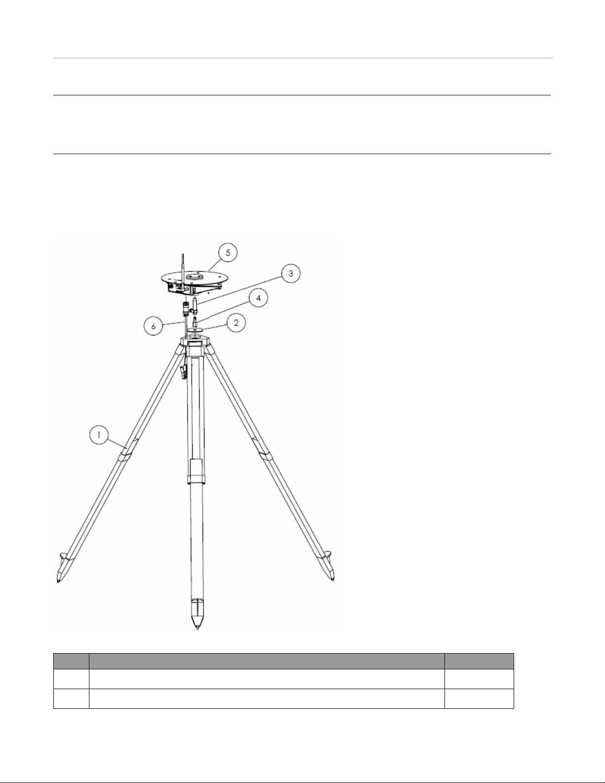
The A5 Steer Base Station components are shown in Figure 2-2 and defined in Table 2-1.
Figure 2-2 A5 Steer Base Station Components (PN: 130-0033-01)
Table 2-1 A5 Steer Base Station Component Definitions and Part Number s
Part Description Part Number
1. Tripod 500-0163-01
2. Mounting Washer 500-0166-01
16 AutoSteer System
Page 19
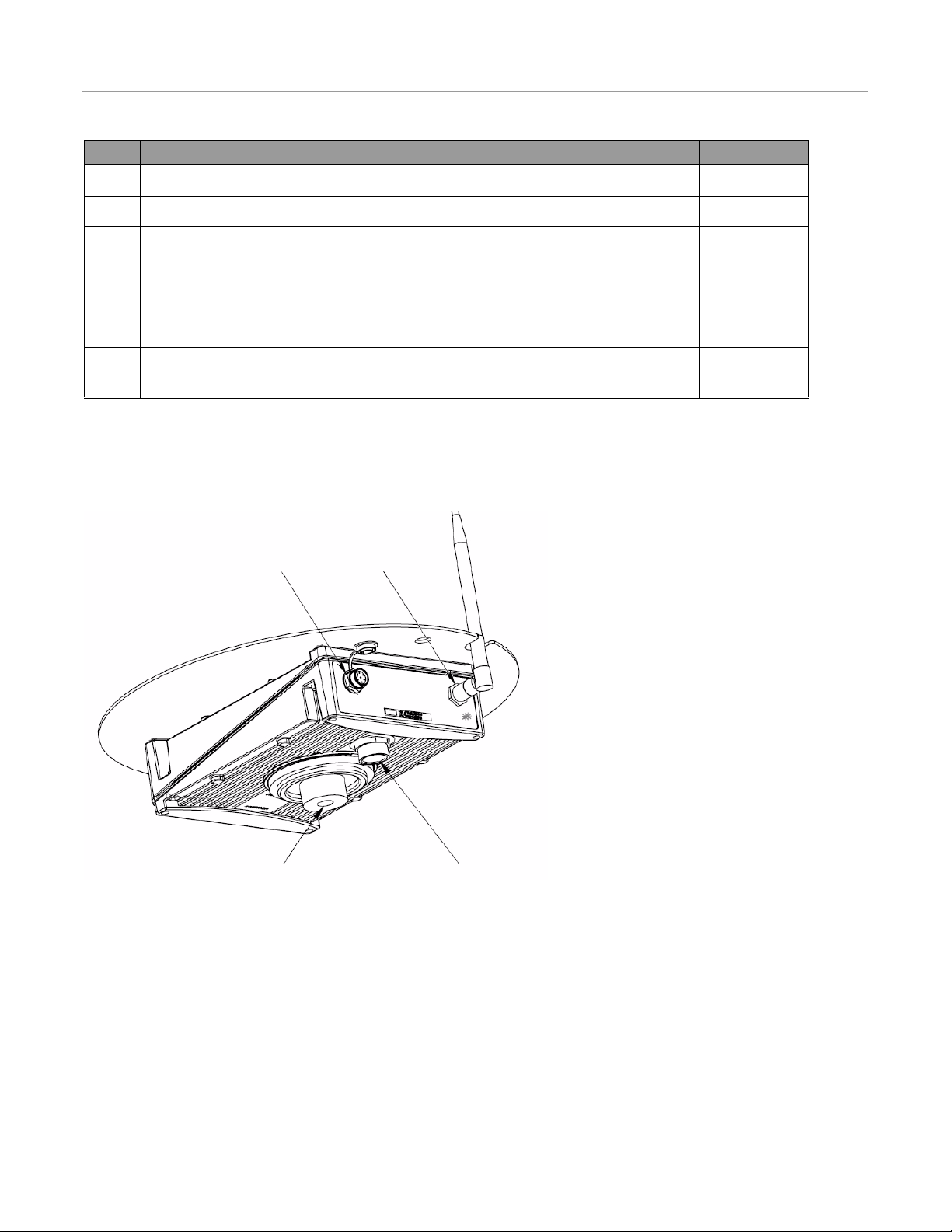
Back and Bottom Panel Hardware and Connectors
Threaded Tripod Mount
Power Connector
Service Port (not used)
D-Link Port
Part Description Part Number
3. Female Quick-Release Coupler (To be attached to the Base Station) 311-0005-01
4. Male Quick-Release Coupler (To be attached to the Tripod mount) 311-0003-01
5. Mobile Base Station (Base station has the following ports and parts):
• Service Port Plug-in (Located on the back of the Base Station labeled SVC)
• Radio Modem Antenna Port (Located on the back of the Base Station labeled DLINK)
• Power Cable Plug-in (Located on the bottom of the Base Station)
• Flexible Radio Modem Antenna (500-0090-01) (Attached to DLINK port
6. 12-Volt Battery Power Supply Cable (A 12-volt marine-type, deep-cycle battery must be
supplied by the operator)
Back and Bottom Panel Hardware and Connectors
The rear and bottom panel hardware is shown in Figure 2-3.
Figure 2-3 A5 Steer Base Station Bottom
200-0196-04
201-0173-01
Faceplate LEDs
The faceplate of the Base Station contains LEDs that indicate system status. Table 2-2 provides details on the LEDs.
Hardware Installation Manual 17
Page 20
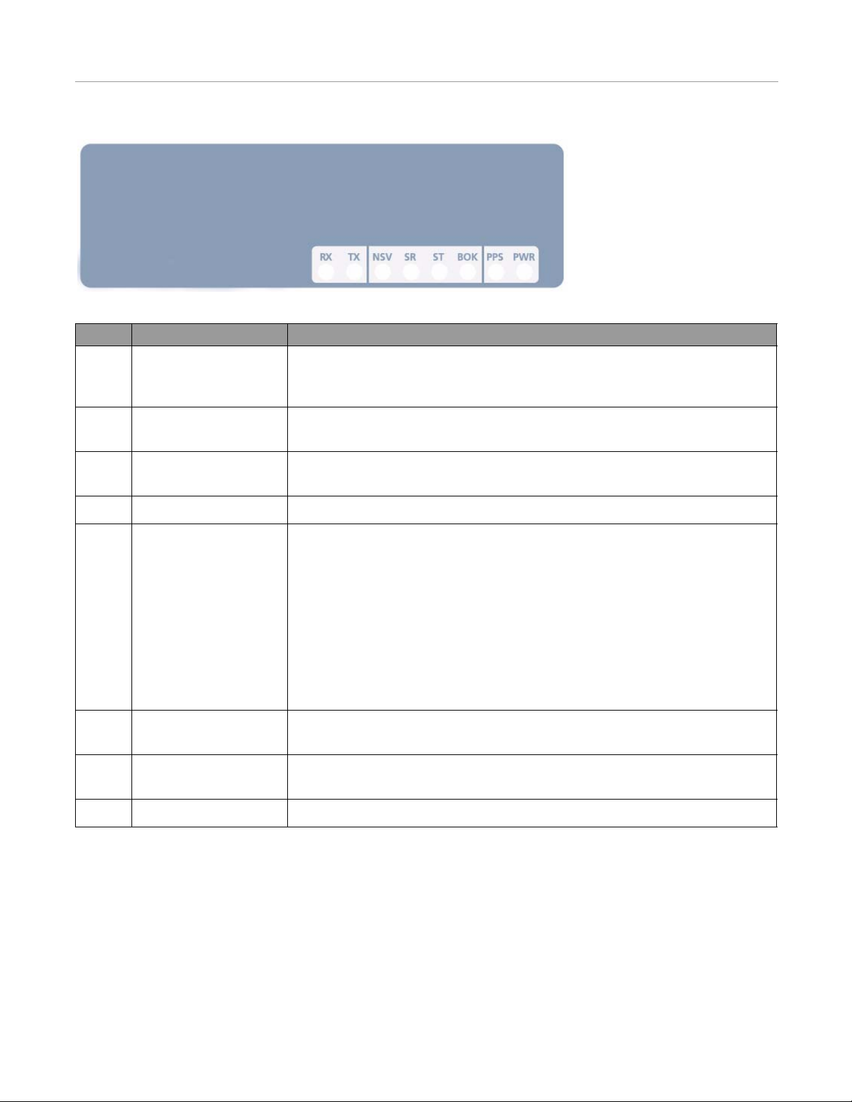
Faceplate LEDs
Figure 2-4 GPS Receiver Faceplate
Table 2-2 LED Display Function Definition
LED Definition Function
RX Receive LED usually is not lit. However, it will occasionally flash indicating a data packet is
being sent from the internal or external radio modem to the Base Station GPS
Receiver.
TX Transmit Blinks as data is transmitted from the Base Station GPS Receiver to the internal or
external radio modem. This can also be steady/green if the data flow is continuous.
NSV Number of GPS Satellites Blinks the number (1-12) of GPS satellites being tracked, then pauses before counting
them again.
SR Service Receive Reserved for diagnostics. LED remains off.
ST Service Transmit This LED is used for diagnostics.
• Immediately after the Base Station is power up, LED will flash the radio channel
programmed for the 900 MHz radio modem. LED will flash rapidly the same
count as the 1st digit of the channel. A long pause indicates the count is going to
move to the 2nd digit. The process repeats for the second and third digits. (A zero
is indicated by ten rapid flashes.)
Example: Six rapid flashes, long pause, ten rapid flashes, long pause and then seven
rapid flashes indicates the Freewave is set to channel 607.
• The ST LED will flash once per second while the Base Station is surveying its
position and then turn on solid after it has calculated its actual position.
BOK Base Unit is OK/active LED turns on solid when the Base St ation determines it has enough voltage to operate
and that the power up procedure was successful and did not have any faults.
PPS Pulse Per Second LED will flash once per second after the Base Station is tracking at least four GPS
satellites and is able to calculate its position.
PWR Power LED turns on solid when the Base Station has power.
18 AutoSteer System
Page 21
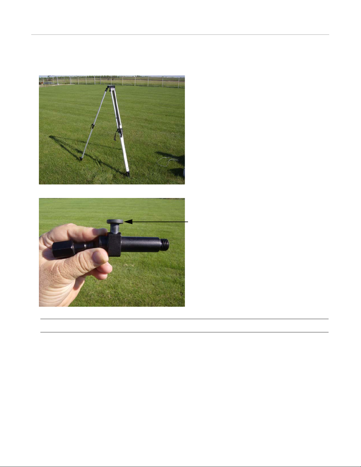
Hardware Setup
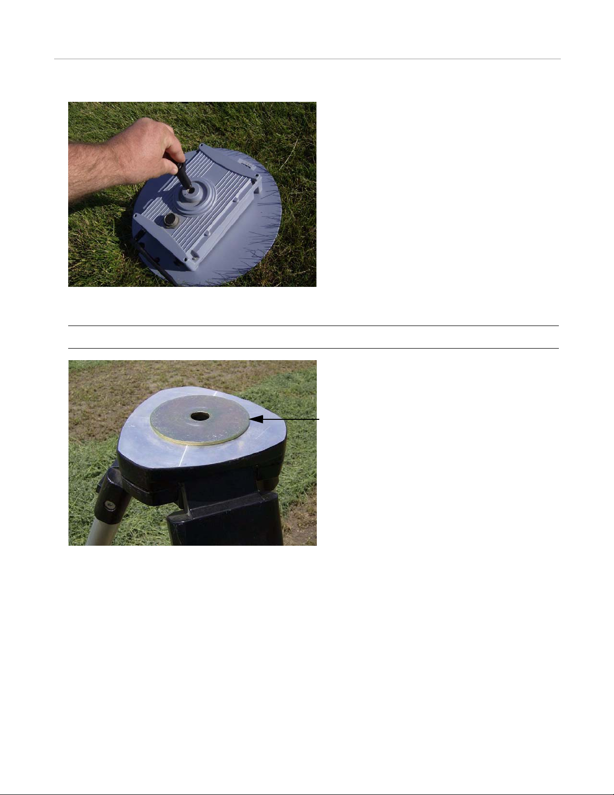
Push the Release Button.
Hardware Setup
1. Set up the Tripod so the mounting plate is level.
2. Press the button on the Female Quick-Release Coupler to separate it from the Male Quick-Release Coupler.
Note: This step can be skipped if the Male Quick-Release Coupler is stored attached to the Tripod.
Hardware Installation Manual 19
Page 22
Hardware Setup
Flat Washer
3. Attach the Female Quick-Release Coupler to the bottom of the Base Station.
4. Place the Washer on top of the Tripod base.
Note: This step can be skipped if the Male Quick-Release Coupler is stored attached to the Tripod.
20 AutoSteer System
Page 23

5. Attach the Male Quick-Release Coupler to the Tripod.
Note: This step can be skipped if the Male Quick-Release Coupler is stored attached to the Tripod.
Hardware Setup
6. Mount the Base Station on top of the Tripod by connecting the Female Quick-Release Coupler to the Male Quick-Release
Coupler.
Hardware Installation Manual 21
Page 24

Providing Power
Radio Modem Antenna
7. Rotate the Radio Modem Antenna into an upright position so it fits through the slot on the ground plane of the GPS
Antenna. Verify that the connector is tight.
Note: The antenna should already be connected into the DLINK port.
Note: Once the two Quick-Release Couplers are attached to their respective components, keep them intact and press
the Female Quick-Release Coupler button to move the Base Station on and off the Tripod.
Providing Power
1. Fasten the 12-Volt Battery Power Supply Cable to the bottom of the Base Station. Do not force the cable connector into the
power cable plug-in. Align the widest, single notch of the connector with the matching slot on the plug-in port.
22 AutoSteer System
Page 25

Providing Power
2. Connect a fully charged 12-volt, deep-cycle marine battery to the power cable using the alligator clips after all the other
connections have been completed and the Base Station is mounted in the proper position.
Note: Since the Base Station does not have a power switch, the connect/disconnect battery cable serves as the switch.
Note: Always start field operations with a fresh, fully charged battery. The battery should not be charged to more than
14 volts and allowed to go less than 12 volts. Operating the Base Station at less then 12 volts can cause RTK
performance issues.
Note: Do not leave the power cable connected to the Base Station overnight (except when allowing the base to survey
in), as the resulting reduced battery power can significantly decrease the effective range of the Base Station’s signal.
Note: A mobile Base Station can also be powered by an AC to 12 volt DC inverter plugged into an outlet. The
power-supply must provide at least 3.0 amps of 12 - 14V DC power.
Note: To turn off the Base Station, disconnect the battery and/or power cable.
Hardware Installation Manual 23
Page 26

Breaking Down the Base Station
Breaking Down the Base Station
1. Disconnect the Base Station from the power supply.
2. Unplug the12-Volt Battery Power Supply Cable from the Base Station.
3. Fold the Radio Modem Antenna so it wraps around the Base Station.
24 AutoSteer System
Page 27

Breaking Down the Base Station
4. Press the Female Quick-Release Coupler button and remove the Base Station from the Tripod.
5. Remove the Female Quick-Release Coupler from the Base Station.
6. Collapse the Tripod. The Flat Washer and Male Quick-Release Coupler can stay attached to the Tripod.
Hardware Installation Manual 25
Page 28

Breaking Down the Base Station
7. Store and transport the A5 Steer Base Station equipment in its case.
26 AutoSteer System
Page 29

AFLink Mobile Base Station
This AFLink Mobile Base Station chapter contains information in the following sections:
• Determine a Mobile Location
• Base Station Components
• Radio Modem Kit Components
• Bottom Panel Hardware and Connectors
• Faceplate LEDs
• Connecting the Components
• Providing Power
• Breaking Down the Base Station
• AFLink Software Configuration
3
Hardware Installation Manual 27
Page 30

Determine a Mobile Location
Determine a Mobile Location
The Base Station GPS Antenna receives position measurements from the GPS satellites. The Base St ation calculates the
position error and transmits the correction data to the vehicle via an AFLink radio modem link. This radio modem link
requires a line-of-sight between the vehicle and the Base Station. The higher the elevation the Radio Modem Antenna is
positioned in, the more easily a vehicle can receive a clear signal. The Base Station is initially setup in an open field with an
unobstructed view of the sky.
Note: Do not place the Base Station adjacent to large metal structures or vehicles which can reflect the GPS signals and
cause interference and multipathing.
Figure 3-1 Improper Mobile Base Station Positioning
Note: To resume using AutoSteer system products on the same rows you need to set the Base Station GPS Antenna up in
the exact location as when you originally worked in that field. This is true whether it is the next day or the next season.
We strongly suggest creating a semi-perm anent mounting for each field site so the Base Station can be precisely relocated
for future use. See the Marking the Base Station's GPS Antenna Location section on page 4 of the Introduction chapter for
descriptions of Base Station mounting methods.
Base Station Components
The AFLink Mobile Base Station components are shown in Figure 3-2 and defined in Table 3-1.
Note: The Mobile Base Station kit and AFLink Base Radio Modem kit are purchased separately. The Radio Modem kit
will vary depending on the frequency required for the system’s region of operation.
28 AutoSteer System
Page 31

Figure 3-2 AFLink Mobile Base Station Components
Base Station Components
Table 3-1 AFLink Mobile Base Station Component Definitions and Part Numbers
Part Description Part Number
1. Tripod 500-0163-01
2. Radio Modem Antenna Bracket Assembly (Includes bracket, Radio Modem Antenna
202-0148-01
Cable, and cable fasteners)
3. Female Quick-Release Coupler (To be attached to the Base Station) 311-0005-01
4. Male Quick-Release Coupler (To be attached to the Tripod mount) 311-0003-01
5. A5 Steer Base Without Radio Mobile Base Station (Base station has the following ports
200-0279-01
and parts):
• Power Cable Plug-in (Located on the bottom of the Base Station)
6. 12-Volt Battery Power Supply and Data Cable (A 12-volt marine-type, deep-cycle
201-0226-01
battery must be supplied by the operator)
7. Radio Modem Mounting Bracket Assembly 200-0197-01
Hardware Installation Manual 29
Page 32

Radio Modem Kit Components
26-pin Amphenol power connectorThreaded Tripod Mount
Radio Modem Kit Components
The Radio Modem Kit components are shown in Figu re 3-3.
Figure 3-3 AFLink Steer Base Radio Modem Components
Bottom Panel Hardware and Connectors
The bottom panel hardware is shown in Figure 3-4.
Figure 3-4 AFLink Mobile Base Station Bottom
30 AutoSteer System
Page 33

Faceplate LEDs
Faceplate LEDs
The LED display indicates system status. The specific symbols and meanings are listed in Table 3-2 (from bottom left to
right).
Figure 3-5 AFLink Mobile Base Station Faceplate
Table 3-2 LED Display Function Definition
Sym Meaning Display
RX Receive (reserved) Reserved for future use.
TX Transmit (data out to the vehicle) Blinks as data is transmitted. This can also be
steady/green if the data flow is continuous.
NSV # of GPS satellites (count = 1-12) Blinks the number of satellites, then pauses before
counting them again.
SR Service receive (modem / RS-232) Reserved for diagnostics.
ST Service transmit (modem / RS-232) Reserved for diagnostics.
BOK Base unit is OK/active; requires a minimum of four
satellites.
PPS Pulse per second (synchronized to GPS time) Blinks once per second.
PWR Power Steady/green [ON] indicates the power is on.
Steady/green [ON] indicates you can start working
on jobs.
Hardware Installation Manual 31
Page 34

Connecting the Components
Connecting the Components
1. Set up the Tripod so the top mounting plate is level.
2. Press the Female Quick-Release Coupler button to separate it from the Male Quick-Release Coupler.
Note: This step can be skipped if the Male Quick-Release Coupler is stored attached to the Tripod.
32 AutoSteer System
Page 35

Connecting the Components
3. Attach the Female Quick-Release Coupler to the bottom of the Base Station.
4. Assemble the Radio Modem Antenna bracket as shown. Attach the Radio Modem Antenna to the bracket and then attached
to one end and the radio modem coax cable to the antenna. Secure the radio modem coax cable to the bracket using the
plastic clips.
Note: This assemble can be kept together when disassembling and storage.
5. Place the Radio Modem Antenna bracket on top of the mounting plate of the Tripod. Attach the Male Quick-Release
Coupler to the Tripod with the attached nut so that it holds the Radio Modem Antenna Mounting Bracket to the top of the
Tripod.
6. Mount the Base Station on top of the Tripod by connecting the female coupler to the male coupler.
7. Attach the Radio Mounting Bracket to the AFLink radio modem.
Note: This bracket can remain attached to the radio modem during transport and storage.
Hardware Installation Manual 33
Page 36

Providing Power
8. Attach the radio modem mounting bracket to one of the Tripod legs so that the radio modem is mounted with the label
upright.
9. Connect the Radio Modem Antenna Cable to the radio modem.
Note: Once the two Quick-Release Couplers are attached to their respective components, keep them intact and press
the Female Quick-Release Coupler button to move the Base Station on and off the Tripod.
Providing Power
1. Fasten the power cable to the bottom of the Base Station. Do not force the cable connector into the power cable plug-in.
Align the widest, single notch of the connector with the matching slot on the plug-in port.
34 AutoSteer System
Page 37

Providing Power
2. Connect a fully charged 12-volt, deep-cycle marine battery to the Base Station power cable using the alligator clips after all
the other connections have been completed and the Base Station is mounted in the proper position.
Note: Since the Base Station does not have a power switch, the connect/disconnect battery cable serves as the switch.
Note: Always start field operations with a fresh, fully charged battery. The battery should not be charged to more than
14 volts and allowed to go less than 12 volts. Operating the Base Station at less then 12 volts can cause RTK
performance issues.
Note: Do not leave the power cable connected to the Base Station overnight, as the resulting reduced battery power
can significantly decrease the effective range of the Base Station’s signal.
Note: A mobile Base Station can also be powered by an AC to 12 volt DC inverter plugged into an outlet. The
power-supply must provide at least 3.0 amps of 12 - 14V DC power.
Note: To turn off the Base Station, disconnect the battery and/or power cable.
Hardware Installation Manual 35
Page 38

Breaking Down the Base Station
Breaking Down the Base Station
1. Disconnect the Base Station from the power supply.
2. Unplug the power cable from the Base Station.
36 AutoSteer System
Page 39

Breaking Down the Base Station
3. Fold the Radio Modem Antenna so it wraps around the Base Station. Press the Female Quick-Release Coupler button and
remove the Base Station from the Tripod.
4. Remove the Female Quick-Release Coupler from the Base Station.
5. Collapse the Tripod. The Washer and Male Quick-Release Coupler can stay attached to the Tripod.
Hardware Installation Manual 37
Page 40

AFLink Software Configuration
6. Store and transport the A5 Steer Base Station equipment in its case.
AFLink Software Configuration
The Base Station AFLink radio modem must have its frequency set to the one that matches the owner’s license. The AutoSteer
system dealer should be able to set this frequency using the AFLink Programming Utility.
To connect the computer to the AFLink radio, the following Technician cables are required:
• Fixed Base Radio Tech Cable (201-0280-01)
• External Radio Tech Cable (201-0221-01)
• Optional Power Supply Cable with Battery Clips (201-0171-01)
• Optional Power Supply Cable with Bare Wires (201-0151-01)
Note: The vehicle radio modem must also be set to the same frequency. See the AFLink Radio Installation Guide for Rovers
for instructions on how to change the frequency of the vehicle radio o r use the AFLink Programming Utility.
38 AutoSteer System
Page 41

AFLink Fixed Base Station
This AFLink Fixed Base Station chapter contains information in the following sections:
• Determining a Location for the AFLink Fixed Base Station
• Hardware Comp on ent S pacing
• AFLink Fixed Base Station Hardware Components
• Base Station Kit
• Radio Modem Kit Components
• Base Station Receiver Faceplate LEDs and Connectors
• Hardware Installation
• Mount GPS Antenna
• Mount Radio Modem Antenna
• Installing the AFLink Radio Modem
• Connecting the GPS and Radio Modem Antennas
• Installing and Powering ON the Base Station
4
The installation of an AFLink Fixed Base Station requires personnel trained in radio communication equipment. If necessary,
your dealer can assist in scheduling a technician to install the permanent Base Station.
Determining a Location for the AFLink Fixed Base Station
The AFLink Fixed Base Station is designed for areas where a structure or radio tower up to 50 feet (15.2 meters) tall and is
centrally located around an operational area. Mounting the Base Station centrally provides radio modem coverage without the
need to move the Base Station from location to location. This type of installation simplifies field and job management as no
Base Station setup is necessary on the job site.
An AFLink Fixed Base Station has sub-inch accuracy for up to 6 miles (9.7 km) surrounding the Base Station’s GPS Antenna.
The range of the Base Station’s radio modem signal is determined by the following factors:
• Height of the Radio Modem Antenna above the surface of the Earth
• Length of the radio modem coax cable
• Size of the Radio Modem Antenna
• The terrain through which the radio modem signals will travel
Obstructions such as buildings, trees, or hills can reduce the range considerably. The radio modem signal may reach further
than 6 miles (9.7 km), but outside that range, accuracy begins to degrade. A clear line-of-sight for the intended coverage area
is critical for radio modem performance.
Hardware Installation Manual 39
Page 42

Hardware Component Spacing
Modem Antenna
GPS Antenna
12v Power
Supply
Standard Wall Outlet
GPS Receiver
Note: The AFLink Fixed Base Station uses an AFLink radio to transmit the radio modem information. The AFLink radio
that is used must be matched to follow the licensing laws for the region where it is installed. Before using an AFLink
radio, verify that the proper frequency has been ordered and that it matches the license held by the owner.
Note: The Base Station Receiver and AFLink radio modem are protected by a weatherproof enclosure supplied with the
kit. Though this enclosure is weatherproof, it should be mounted in a location where it is protected from direct sunlight this helps keep the component cool. This enclosure should be mounted near the ground for easy access for service and
maintenance of the equipment inside.
Hardware Component Spacing
This installation kit comes standard with a 30 feet (9.1 Meter) GPS Antenna cable, a 50 feet (15.2 Meter) Radio Modem
Antenna, and a 3dBi Radio Modem Antenna. Longer coax cables and a higher gain antenna can be substituted in the kit to
provide more flexibility and additional range in the installation. Contact your AutoSteer dealer to customize the order if the
installation requires it. The spacing of hardware components is described below:
• The Radio Modem Antenna can be separated from the AFLink radio by up to 50 feet (15.3 meters) of LMR 400 antenna
• The Base Station GPS Antenna and Receiver can be separated by up to 100 feet (30.5 meters) of LMR400 antenna cable.
Figure 4-1 shows a typical permanently-mounted Base Station installation.
Figure 4-1 Permanent Base Station Positioning
cable. It is best to have this cable as short as possible for maximum signal range.
40 AutoSteer System
Page 43

AFLink Fixed Base Station Hardware Components
AFLink Fixed Base Station Hardware Components
The AFLink Fixed Base Station comes in two hardware kits: (1) a Base Station Kit, and (2) An AFLink Radio Modem Kit.
The components in these kits are described in the sections that follow.
Base Station Kit
The AFLink Fixed Base Station components are shown in Figure 4-2.
Figure 4-2 AFLink Fixed Base Station Components
Hardware Installation Manual 41
Page 44

Radio Modem Kit Components
Radio Modem Kit Components
The Radio Modem Kit components are shown in Figu re 4-3.
Figure 4-3 Radio Modem Kit Components
Base Station Receiver Faceplate LEDs and Connectors
The faceplate of the Base Station contains LEDs that indicate system status. Table 4-1 provides details on the LEDs. The
faceplate also contains the following port (see Figure 4-4):
• GPS Antenna Port [B]
Note: The Base Station Receiver is mounted inside the enclosure, behind a mounting plate.
Figure 4-4 GPS Receiver Faceplate
42 AutoSteer System
Page 45

Hardware Installation
Table 4-1 LED Display Function Definition
LED Definition Function
RX Receive LED usually is not lit. However, it will occasionally flash indicating a data packet is
being sent from the internal or external radio modem to the Base Station GPS
Receiver.
TX Transmit Blinks as data is transmitted from the Base Station GPS Receiver to the internal or
external radio modem. This can also be steady/green if the data flow is continuous.
NSV Num ber of GPS Sat ellites Blinks the number (1-12) of GPS satellites being tracked, then pauses before counting
them again.
SR Service Receive Reserved for diagnostics. LED remains off.
ST Service Transmit This LED is used for diagnostics.
• Immediately after the Base Station is power up, LED will flash the radio channel
programmed for the 900 MHz radio modem. LED will flash rapidly the same
count as the 1st digit of the channel. A long pause indicates the count is going to
move to the 2nd digit. The process repeats for the second and third digits. (A zero
is indicated by ten rapid flashes.)
Example: Six rapid flashes, long pause, ten rapid flashes, long pause and then seven
rapid flashes indicates the Freewave is set to channel 607.
• The ST LED will flash once per second while the Base Station is surveying its
position and then turn on solid after it has calculated its actual position.
BOK Base Unit is OK/active LED turns on solid when the Base Station determines it has enough voltage to operate
and that the power up procedure was successful and did not have any faults.
PPS Pulse Per Second LED will flash once per second after the Base Station is tracking at least four GPS
satellites and is able to calculate its position.
PWR Power LED turns on solid when the Base Station has power.
Hardware Installation
The installation of an AFLink Fixed Base station is broken down into the following steps:
• Mount GPS Antenna
• Mount Radio Modem Antenna
• Installing the AFLink Radio Modem
• Connecting the GPS and Radio Modem Antennas
• Installing and Powering ON the Base Station
Mount GPS Antenna
1. Identify a mounting location for the GPS Antenna that is close enough to the Base Station Receiver mounting location that
the cables can be connected.
Note: The installation kit does not come with a mounting bracket for the GPS Antenna. This must be built by the
installer or supplied by the owner.
Hardware Installation Manual 43
Page 46

Mount GPS Antenna
Note: The Base Station GPS Antenna mounting position must be in a sturdy, unmovable place. This can be on top of
a sturdy building or on a solid pole near the ground. We do not recommend mounting this antenna on a tower or grain
leg as they generally are not sturdy enough to prevent movement.
Note: The GPS Antenna must have a clear view of the sky. If there is going to be an obstruction, it is best to place the
GPS Antenna on the south side of the obstruction in the northern hemisphere and on the north side of it on the
southern hemisphere. Position the antenna as far away from the obstruction as possible.
Note: Do not mount the Base Station GPS Antenna adjacent to large metal structures, next to towers, or any guy wires
that can reflect the GPS signals and cause interference and multiplexing.
Figure 4-5 Correct Base Station GPS Antenna Positioning
44 AutoSteer System
Page 47

Figure 4-6 Incorrect Base Station GPS Antenna Positioning
Mount GPS Antenna
2. Mount the GPS Antenna.
3. Attach the right angle connector of the GPS Antenna Cable to the GPS Antenna.
Hardware Installation Manual 45
Page 48

Mount Radio Modem Antenna
4. Route the GPS Antenna Cable from the GPS Antenna to the Base Station Receiver. Secure the cable all along the route to
keep it from being damaged.
Mount Radio Modem Antenna
1. Assemble the Radio Modem Antenna bracket to the Radio Modem Antenna. Connect the Radio Modem Antenna to the
Prism pole.
2. Identify a mounting location for the Radio Modem Antenna that is as high as possible and close enough to the Base Station
Receiver mounting location that the cables can be connected.
Note: The Radio Modem Antenna must be located close enough to where the Base Station is going to be mounted so
that the cable will reach.
Note: The Radio Modem Antenna needs to be visible from all directions so that the mobile vehicles can have a clear
line of site.
Note: Do not mount the Radio Modem Antenna next to the side of a building or radio tower. It should be mounted at
the highest point possible.
Note: If the antenna must be mounted on the side of tower, be sure to space the antenna at least 6 feet (1.8 meters)
from the tower on the side of the tower where the most distance is required. The radio signals will be partially blocked
on the opposite side of the tower.
46 AutoSteer System
Page 49

Mount Radio Modem Antenna
Note: The Radio Modem Antenna can move slightly after being installed without having any effect on the
performance of the RTK system. Mounting this antenna on top of a radio tower or grain leg is acceptable to provide
maximum range.
Figure 4-7 Correct Base Station Radio Modem Antenna Positioning
Figure 4-8 Incorrect Base Station Radio Modem Antenna Positioning
3. Mount the Radio Modem Antenna.
Hardware Installation Manual 47
Page 50

Mount the Base Station Enclosure
4. Attach the connector of the Radio Modem Antenna Cable to the Radio Modem Antenna.
5. Route the Radio Modem Antenna Cable from the Radio Modem Antenna to the Base Station Receiver . Secure the cable all
along the route to keep it from being damaged.
Mount the Base Station Enclosure
1. Install the Base Station enclosure firmly against a wall or other sturdy structure that is easily accessible and near a power
source. The antenna cable and power connectors must be pointed downward to prevent moisture build up. Use the
appropriate screws to secure the enclosure to the specific wall material being used.
2. Connect a good copper ground strap to the ground stud.
Note: The ground strap must be connected to an effective earth ground to unload a lightning surge.
48 AutoSteer System
Page 51

Installing the AFLink Radio Modem
3. Install the earth ground per the local regulations that specify lightning protection grounding.
Note: Picture shows other connections already connected.
Installing the AFLink Radio Modem
1. Loosen the 2 - Phillips screws on clamps holding enclosure door closed. The screws are located on the right side of the
enclosure.
Note: The screws do not need to be completely removed. They can be loosened until the clamp can be slid from over
the lip holding the door closed.
Hardware Installation Manual 49
Page 52

Installing the AFLink Radio Modem
2. Use the enclosed key to open the lock on the enclosure. Pull the door open to access the interior.
3. The Base Station Receiver is accessible by loosening the two screws that hold the internal panel closed.
Note: It is not necessary to remove these screws during installation. This is shown to demonstrate how to service the
Receiver.
50 AutoSteer System
Page 53

Installing the AFLink Radio Modem
4. To service the Base Station Receiver, four bolts need to be removed so the Receiver can be removed from the enclosure.
Note: It is not necessary to remove these bolts during installation. This is brought up for reference in case the
Receiver needs to be serviced in the future.
5. The AFLink radio modem is mounted to the mounting plate. Remove the four screws in the mounting plate.
Hardware Installation Manual 51
Page 54

Installing the AFLink Radio Modem
6. Install AFLink radio modem and reattach using screws that were just removed.
7. Connect the Radio Modem Antenna lead from the enclosure to the left antenna connector on the AFLink radio modem.
8. Connect the radio modem power/data cable from the Base Station Receiver to the power/data port of the AFLink radio
modem.
52 AutoSteer System
Page 55

Connecting the GPS and Radio Modem Antennas
9. The AFLink radio modem has now been properly installed. Close the enclosure door, lock with the enclosed key, and
clamp sides of enclosure with clamps to ensure the box is weatherproof.
Note: Keep the key in a secure place.
Connecting the GPS and Radio Modem Antennas
1. Attach the GPS Antenna cable to the GPS (blue) connector on the bottom of the enclosure. Verify that the connector
adapter is present. Hand tighten only.
Note: Inverted coax cable connections immediately damage the GPS Antenna when the Base Station is turned on.
Verify the cable colors match the colors on the identification label.
Hardware Installation Manual 53
Page 56

Installing and Powering ON the Base Station
2. Attach the Radio Modem Antenna Cable to the radio modem (red) connector on the bottom of the enclosure. Hand tighten
only.
Note: Inverted coax cable connections immediately damage the GPS Antenna when the Base Station is turned on.
Verify the cable colors match the colors on the identification label.
Installing and Powering ON the Base Station
1. Attach the power supply cable to the connector on the bottom of the enclosure.
2. Connect the other end of the power supply cable to a 12.0 volt power supply.
Note: If the AC to DC inverter supplied with the AFLink Base Station is used, it must be supplied with AC voltage
and enclosed in it own weather proof enclosure. Power supply options and installations are the responsibility of the
owner.
54 AutoSteer System
Page 57

Installing and Powering ON the Base Station
3. After attaching all connectors to supply power to the Base Station, turn the power inverter’s power switch to the ON
position.
Note: Verify that all antennas and antenna cables have been installed and are properly mounted before supplying
power to the Base Station enclosure. Failure to do this may cause damage to the radio components.
Note: The Base Station begins transmitting RTK correction signals within a minute of powering up. Depending on the
firmware version loaded on the Base Station and the Base Station’s survey status, it may take 24 hours or more for the
Base Station to start transmitting absolute position fixes.
Note: The Base Station can be powered from a 12.0 volt battery if a 120 VAC power source is not available or a
power failure has occurred.
Note: To turn off the Base Station power, unplug the power connector from the bottom of the Base Station enclosure
or turn off the switch on the power inverter.
Hardware Installation Manual 55
Page 58

Installing and Powering ON the Base Station
56 AutoSteer System
Page 59

A5 and AFLink Repeaters
This A5 and AFLink Repeaters chapter contains information in the following sections:
• Introduction to A5 and AFLink Repeaters
• Repeater Concepts
• Determining a Location for the Repeater
• Using a Repeater
• Daisy Chaining
• Multiple Repeater Setup
• Incorrect Repeater Usage
• Hardware Comp on ents
• A5 Repeater Components
• AFLink Repeater Components
• Assembling the Repeater
• Mounting Options
• Tripod Mounting
• Using a Pole Mount
• Mounting in a Permanent Location
• Providing Power
• Breaking Down the Repeater
5
Hardware Installation Manual 57
Page 60

Introduction to A5 and AFLink Repeaters
Introduction to A5 and AFLink Repeaters
There are two versions of the Repeater. They are the A5 Repeater and the AFLink Repeater. The A5 Repeater works with all
the Base Stations versions that use the 900 MHz radio modem. The AFLink Repeater works with all the Base Station versions
that use the 400 MHz AFLink radio modems. Both versions allow the Base Station signal to be broadcasted around obstacles;
however there are some differences in the way the different radios work. This chapter will explain how both the A5 and
AFLink Repeaters work in general and then also explain the specific limitations of each model.
Repeater Concepts
For RTK applications, the Base Station GPS Receiver receives GPS satellite signals and then transmits precise positioning
data to the vehicle via its radio modem link. The radio modem link requires a line-of-sight between the vehicle and the Base
Station. In some cases there may be an obstruction such as trees, buildings, or hills between the Base Station and the vehicle.
When this condition occurs, it is necessary to find a way to transmit the Base Station signal around the obstacle.
A repeater is a stand alone radio data modem that is placed in an area that is visible from both the Base Station and the vehicle.
The repeater receives the signal from the Base Station and then retransmits it to the vehicle. Repeaters can be used to fill in the
Base Station coverage area. However, they cannot be used to extend sub-inch coverage beyond the maximum Base Station
range of approximately 6 miles (9.7 km) from the Base Station's GPS Antenna. The repeater requires only a 12-Volt power
source and a fixed radio antenna to operate.
Before using a repeater, it must be programmed to work with your particular Base Station.
• A5 Repeaters must be set to the same channel as the Base Station. The radio channel should be set by the factory, but it can
also be set by your dealer.
• AFLink Repeaters must be set to the corresponding Base Station frequency. The frequency should be set by the factory , but
it can also be set by your dealer.
58 AutoSteer System
Page 61

Determining a Location for the Repeater
Determining a Location for the Repeater
The repeater must be placed in a location that is within line-of-sight of both the Base Station and the vehicle. The exact
location of a repeater does not affect job repeatability. The Base Station’s GPS Antenna is always the reference position for
repeatability. Figure 6-1 shows a common repeater -Base S tation setup in a typical field. Alternate configurations are described
later in this chapter.
• B represents the location of the Base Station transmitter.
• R indicates the location of the Repeater.
• The shaded area labeled (1) indicates Repeater coverage only.
• The shaded area labeled (2) indicates coverage by both the Base Station and the Repeater.
• The shaded area labeled (3) indicates Base Station coverage only.
• The shaded area labeled (4) indicates no coverage by either the Base Station or the Repeater (or the area is outside the
sub-inch accuracy coverage area of the Base Station).
Figure 5-1 Base Station and Repeater Coverage Area
Hardware Installation Manual 59
Page 62

Using a Repeater
Using a Repeater
There are three main features and configuration options to keep in mind when using a repeater. Before ordering a repeater
discuss these needs with your AutoSteer dealer and verify they will work in your situation. The three options are:
• Daisy Chaining
• Multiple-Repeater Setup
Daisy Chaining
In some situations, one Repeater may not provide adequate coverage for the area around a Base Station. In this case it is
sometimes possible to use multiple Repeaters to help fill in the gaps. In order to set up more than one Repeater to work with a
Base Station, one repeater must be set to Repeater 1 and the other set to Repeater 2 from the factory or by your AutoFarm
dealer.
Daisy chaining is when a Base Station sends a signal to Repeater 1 and then Repeater 1 sends the signal on to Repeater 2.
Repeater 2 then sends the RTK data to the vehicle. In this case Repeater 2 cannot directly get a signal from the Base Station.
Using repeaters in this manner enables the user to get a RTK signal around a large obstacle.
A5 Repeaters
The A5 Repeater will allow Daisy Chaining. It is limited to two repeaters in the chain. Repeater 1 needs to be configured to
Repeater 1 and placed closest to the Base Station signal. Repeater 2 needs to be configured as Repeater 2 and placed near
Repeater 1. It is a good practice to physically label the Repeaters 1 and 2 to ensure they are kept separate.
AFLink Repeaters
The AFLink Repeater will not allow Daisy Chaining. The radio modems do not have the capacity to transmit the RTK data
through the second Repeater.
Note: Repeater 2 cannot be used to extend the sub-inch signal range of the Base Station outside the 6 mile (9.7 km)
coverage area of the Base Station itself. It should only be used to get the signal around an obstacle and transmitted to an
area where the vehicle is still within 6 miles (9.7 km) of the Base Station's GPS Antenna.
Note: Every time the data is transmitted through a repeater, the effective amount of data the repeater can transmit is cut
in half. Because of the way each radio modem system (A5 and AFLink) sends data, Daisy Chaining my not always be
possible. Check the limitations for the system being used before attempting to configure the Repeater for Daisy Chaining.
60 AutoSteer System
Page 63

Daisy Chaining
Figure 6-2 shows an example of repeaters being set up in a daisy chain configuration.
• The shaded area labeled (6) no coverage by a RTK signal (or are outside the 6 mile (9.7 km) range of the Base Station).
• The shaded area labeled (5) indicate coverage by the Base Station transmitter (B) only.
• The shaded area labeled (4) indicate coverage by the Base Station and Repeater 1 (R1).
• The shaded area labeled (3) indicate coverage by the Base Station, Repeater 1, and Repeater 2 (R2).
• The shaded area labeled (2) indicate coverage by Repeater 1 and Repeater 2.
• The shaded area labeled (1) coverage by Repeater 2 only.
Figure 5-2 Example of Repeaters Set up in Daisy Chain
Hardware Installation Manual 61
Page 64

Multiple Repeater Setup
Multiple Repeater Setup
Multiple repeaters can also be set up in various locations around the Base Station to repeat signals from the same Base Station.
In this scenario both repeaters can receive correction signals from the Base Station, but they cannot communicate with each
other. In this case, an obstacle may block pa rt of the path of the Base Station signal in more than one direction. A repeater can
be set up on both sides of the obstacle and the RTK correction signal scan be transmitted around those obstacles. One repeater
must be set up as repeater 1 and the other as Repeater 2 from the factory or by your AutoSteer dealer.
A5 Repeater
The A5 Repeater will allow Multiple Repeaters connections to one Base Station. One Repeater must be configured as Repeater
1 and the other configured as Repeater 2. The Repeaters themselves should be positioned so they cannot see each other
otherwise the radio signals could be confused.
AFLink Repeaters
The AFLink Repeater will also allow Multiple Repeaters connections to one Base Station. One Repeater must be configured as
Repeater 1 and the other configured as Repeater 2. The Repeaters themselves should be positioned so they cannot see each
other otherwise the radio signals could be confused.
Figure 6-3 shows a possible configuration where more than one repeater is transmitting correction signals from the same Base
Station.
• The shaded area labeled (1) indicates the intersection of coverage by the Base Station (B), Repeater 1 (R1), and Repeater
2 (R2).
• The shaded area labeled (2) indicates an overlap of coverage by the Base Station overlaps at least one of the repeaters.
• The shaded area labeled (3) indicates coverage by the Base Station only.
• The shaded area labeled (4) indicates an overlap of coverage by Repeater 1 and Repeater 2.
• The shaded area labeled (5) indicates coverage from either Repeater 1 or Repeater 2 only.
• The shaded area labeled (6) indicates no coverage (or the correction signals are outside the Base Station’s 6 mile (9.7 km)
range).
Figure 5-3 Repeaters Working off the Same Base Station
62 AutoSteer System
Page 65

Incorrect Repeater Usage
Incorrect Repeater Usage
The repeater cannot be used to extend the Base Station sub-inch accuracy range in the manner shown in Figure 6-4. In this
example the vehicle is being driven inside the coverage area of the repeater. However the vehicle is outside the Base Station’s
original 6 mile (9.7 km) effective range. The vehicle may not achieve sub-inch accuracy in this area.
Note: Signal delays between the Base Station and the vehicle in this situation can also make the RTK signal unreliable or
unusable.
Figure 5-4 Incorrect Repeater Usage
Hardware Installation Manual 63
Page 66

Hardware Components
Hardware Components
This section describes the hardware components that are shipped with each version of Repeater. An optional Tripod
(500-0163-01) for installing the repeater in portab le appl ications and a 4 foot (1.2 Meter) pole section (500-0003-01) or 12
foot (3.6 meter) pole kit (200-0315-01) for installin g the repeater in permanent instal lations are also available and can be
ordered separately to facilitate optional mounting situations.
A5 Repeater Components
The A5 Repeater components are shown in Figure 5-5 and defined in Table 5-1.
Figure 5-5 A5 Repeater Components
Table 5-1 Repeater Component Definitions and Part Numbers
Part Description Part Number
1. A5 Repeater Radio Modem 280-0004-01
2. Repeater Power Cable 201-0205-01
64 AutoSteer System
Page 67

Part Description Part Number
3. Radio Modem Bracket Assembly 200-0334-01
4. 6 dBi Antenna 500-0006-01
5. Repeater Modem Antenna Cable 201-0246-01
AFLink Repeater Components
The AFLink Repeater components are shown in Figure 5-6and defined in Table 5-2.
Figure 5-6 AFLink Repeater Components
AFLink Repeater Components
Table 5-2 Repeater Component Definitions and Part Numbers
Part Description Part Number
1. Repeater Power Cable 201-0205-01
2. Repeater Antenna Cable 201-0246-01
Hardware Installation Manual 65
Page 68

Assembling the Repeater
Part Description Part Number
3. Repeater Bracket Assembly 200-0334-01
4. Antenna 500-0006-01
5. AFLink Radio 201-0246-01
Assembling the Repeater
1. Assemble the Radio Modem Bracket Assembly as shown in the diagram. The U-bolts and Washer are to be used later if
necessary. The final assembly is shown on the right.
2. Attach the A5 Repeater Radio Modem to the Radio Modem Bracket Assembly using the four screws provided.
3. Attach the Radio Modem Antenna to the back of the Radio Modem Bracket Assembly and tighten the bolts that secure it to
the bracket.
4. Connect the Repeater Modem Antenna Cable to the bottom of the Radio Modem Antenna on one end and to the top of the
Repeater Radio Modem on the other end.
5. Connect the Repeater Power Cable to the bottom of the Repeater Radio Modem.
66 AutoSteer System
Page 69

Mounting Options
Mounting Options
The repeater can be mounted on a Tripod, pole or other permanent location as described in the following sections.
Tripod Mounting
If the optional Tripod (500-0163-01) has been ordered use the following procedure to set up the Repeater.
1. Set up the Tripod so the mounting plate is level.
2. Place the Washer on top of the Tripod base.
3. Firmly attach the repeater to the Tripod with the Tripod nut.
4. Verify that the antenna is perpendicular to the ground after it is set up.
Hardware Installation Manual 67
Page 70

Using a Pole Mount
Using a Pole Mount
If the optional 4 foot (1.2 Meter) pole section (500-0003-01) or 12 foot (3.6 meter) pole kit (200-0315-01) has been ordered,
use the following instructions to mount the Repeater.
1. Set mounting pole in the desired location.
2. Screw repeater assembly to the top of the mounting pole.
68 AutoSteer System
Page 71

3. Verify that the antenna is perpendicular to the ground after it is set up.
Mounting in a Permanent Location
1. Mount mounting bracket to permanent site.
Mounting in a Permanent Location
2. Attach the repeater assembly to permanent mounting bracket using U-bolts.
3. Verify that the antenna is perpendicular to the surface of the Earth after it is set up.
Providing Power
1. Connect a fully charged12-volt, deep-cycle marine battery to the power cable using the alligator clips after all of the other
connections have been completed. Since the repeater does not have a power switch, the connect/disconnect battery cable
serves as the switch.
Hardware Installation Manual 69
Page 72

Breaking Down the Repeater
Note: Always start field operations with a fresh, fully charged battery. The battery should not be charged to more than
14 volts or enabled to go to less than 12.0 volts. Operating the repeater at less than 12.0 volts can cause erratic data
transfer problems.
Note: Do not leave the power cable connected to the repeater overnight, as the resulting reduced battery power can
significantly decrease the effective range of the signal.
Note: A repeater can also be powered by an AC to 12.0 Volt DC inverter plugged into an outlet. The power-supply
must provide at least 3.0 amps of 12 - 14V DC.
Note: To turn off the repeater, disconnect the battery and/or power cable.
Breaking Down the Repeater
If the repeater is to be moved, use the following procedure to break down the repeater for transportation and storage:
1. Disconnect the repeater from the power supply.
2. Disconnect the repeater from the mount.
3. Store the repeater equipment in a safe place and transport to next location.
70 AutoSteer System
 Loading...