

Page 1

Agilent E1439
VXI 70 MHz IF ADC
with filters and memory
User’s Guide
Agilent Technologies Part Number E1439-90005
Printed in U.S.A.
Print Date: December 2002, Third Edition
© Agilent Technologies, Inc. All rights reserved.
8600 Soper Hill Road, Everett, Washington 98205-1209 U.S.A.
Page 2

Notices
The information contained in this manual is subject to change without notice.
Agilent Technologies makes no warranty of any kind with regard to this manual, including, but
not limited to, the implied warranties of merchantability and fitness for a particular purpose.
Agilent Technologies shall not be liable for errors contained herein or direct, indirect, special,
incidental, or consequential damages in connection with the furnishing, performance, or use of the
material.
TRADEMARKS
Windows®, MS Windows®, Windows NT® are U.S. registered trademarks of Microsoft
Corporation.
WA R RA N T Y
A copy of the specific warranty terms applicable to your Agilent Technologies product and
replacement parts can be obtained from your local Sales and Service Office.
This document contains proprietary information which is protected by copyright. All rights are
reserved. No part of this document may be photocopied, reproduced or translated to another
language without the prior written consent of Agilent Technologies, Inc.. This information
contained in this document is subject to change without notice.
Use of this manual and CD-ROM supplied for this pack is restricted to this product only.
Additional copies of the programs can be made for security and back-up purposes only.
RESTRICTED RIGHTS LEGEND
Use, duplication or disclosure by the U.S. Government is subject restrictions as set forth in
subparagraph (c)(1)(ii) of the Rights in Technical Data and Computer Software clause in DFARS
252.227-7013
Agilent Technologies, Inc.
395 Page Mill Road
Palo Alto, CA
94303-0870 USA
Rights for non-DOD U.S. Government Departments and Agencies are set forth in FAR 52.22719(c)(1,2).
Copyright © 2000-2002 Agilent Technologies, Inc.
2
Page 3
The Agilent E1439 at a Glance
The Agilent E1439 95 MSa/s Digitizer with DSP and Memory provides high precision digitizing
for time and frequency domain applications along with signal conditioning, filtering, and
memory. The module plugs into a single C-size slot in a VXI mainframe.
E1438/
E1439
Number of Channels 1
Type of Inputs 50 ohm
Input Bandwidth 150 MHz, 36 MHz alias protected
Sample Rate 95 Msample/s
Input Range −36 to +12 dBm
Raw ADC resolution 12 bits
VXI Bus Support VME (and Local Bus E1439D only)
VXI Device Type Register based
I/O Data Port (E1439D only) Fiber optic serial FPDP (front panel data port)
Size C-sized, single slot
3
Page 4

What You Get With the Agilent E1439
The following items are included with your Agilent E1439:
Hardware
• Agilent E1439 ADC, C-size VXI module
• CD-ROM for Windows setup
Software
• CD-ROM for installation
A Windows setup program that installs:
• Firmware installation program
• The Agilent E1439 VXIplug&play libraries and drivers
• Soft Front Panel program for the Agilent E1439 with source files
• Web-based help for the Agilent E1439
• AGDSP function library and online help
• Example programs and source files
• Microsoft Visual C++ C-library and source files
• Microsoft Visual Basic header files
Documentation
• Agilent E1439 Installation and Service Guide
• Online documentation available after software installation:
• Agilent E1439 User’s Guide in PDF format (this document)
• Web-based help files providing operational information and programmer’s reference
• WinHelp files for the Agilent E1439 Soft Front Panel
4
Page 5

In This Book
This book documents the Agilent E1439 module. It provides:
• hardware installation information
• software installation information
• getting started information
• operational information
• programmer’s reference
• replaceable parts
Other Documentation
Installation and Service information is provided as a printed document as well as in this PDF
document.
After running the setup program the following documentation is available:
• Web-based help files are available from the Start menu.
• WinHelp for the Soft Front Panel is available from the application.
5
Page 6

6
Page 7

Contents
1 Installing the Agilent E1439
ToinspecttheAgilentE1439...................................2
To install the Agilent E1439....................................3
To clean fiber optic connectors .................................6
Tostorethemodule ..........................................7
Totransportthemodule.......................................7
2 Getting Started with the Agilent E1439
Getting Started and Introduction ...............................10
SystemRequirements........................................11
To install the Windows VXIplug&play drivers....................12
TousetheResourceManager .................................13
To use the program group (Windows) ...........................14
To use the VXIplug&play SoftFrontPanel(SFP)..................15
Tousetheexampleprograms..................................16
3 Using the Agilent E1439
Agilent E1439 overview......................................20
Programming the Agilent E1439 ...............................21
Themeasurementloop.......................................23
Delayandphaseintriggeredmeasurements ......................25
Magnitude trigger and magdwell time ...........................28
Frequencyandfiltering.......................................30
Usingclockandsync........................................31
Managing multiple modules...................................32
Transferringdata ...........................................42
FiberOpticInterface.........................................43
4 Agilent E1439 Programmer's Reference
Introduction ...............................................54
Functionslistedbyclass......................................55
Functionslistedbyfunctionalgroup ............................60
Functionslistedalphabetically.................................67
age1439_adc_clock . . .......................................72
age1439_adc_divider . .......................................73
Page 8

Contents
age1439_attrib_get ..........................................74
age1439_cal_get ............................................75
age1439_clock_fs ...........................................76
age1439_clock_recover . . . ...................................77
age1439_clock_setup ........................................78
age1439_close .............................................86
age1439_combo_setup .......................................87
age1439_data_memsize_get...................................88
age1439_data_scale_get . . . ...................................89
age1439_data_setup .........................................90
age1439_data_xfersize .......................................96
age1439_driver_debug_level ..................................97
age1439_epoch_setup........................................98
age1439_error_message . . . ..................................102
age1439_error_query .......................................103
age1439_ext_sample_sync . ..................................104
age1439_fiber_clear ........................................106
age1439_fiber_error_clear . ..................................107
age1439_fiber_error_get . . ..................................108
age1439_fiber_LED_get . . ..................................110
age1439_fiber_rcv_signals_get ...............................111
age1439_fiber_setup........................................112
age1439_fiber_signal_get. . ..................................115
age1439_fiber_verify .......................................116
age1439_fiber_xmt_BOF . . ..................................117
age1439_fiber_xmt_signals ..................................118
age1439_fiber_xmt_signals_get...............................119
age1439_filter_setup .......................................120
age1439_filter_sync ........................................123
age1439_frequency_center_raw ...............................125
age1439_frequency_center_raw_compute .......................127
age1439_frequency_setup . ..................................128
age1439_front_panel_clock_input .............................131
age1439_init ..............................................132
age1439_input_autozero. . . ..................................134
age1439_input_offset .......................................135
age1439_input_offset_save ..................................136
age1439_input_range_auto. ..................................137
age1439_input_range_convert ................................138
age1439_input_setup .......................................141
age1439_interrupt_restore . ..................................145
age1439_interrupt_setup . . ..................................146
age1439_lbus_mode ........................................148
age1439_lbus_reset ........................................150
age1439_meas_control ......................................151
age1439_meas_init .........................................154
age1439_meas_start ........................................155
age1439_meas_status_get . ..................................156
8
Page 9

Contents
age1439_options_get . ......................................157
age1439_product_id_get ....................................158
age1439_read .............................................159
age1439_read_raw . . . ......................................162
age1439_reference_clock ....................................165
age1439_reference_prescaler .................................166
age1439_reset .............................................167
age1439_reset_hard . . ......................................168
age1439_revision_query.....................................169
age1439_self_test ..........................................170
age1439_serial_number .....................................172
age1439_smb_clock_output ..................................173
age1439_state_recall . ......................................174
age1439_state_save . . ......................................175
age1439_status_get. . . ......................................176
age1439_sync_clock. . ......................................178
age1439_sync_direction .....................................179
age1439_sync_output . ......................................180
age1439_trigger_delay_actual_get.............................181
age1439_trigger_phase_actual_get ............................182
age1439_trigger_setup ......................................183
age1439_vcxo.............................................187
age1439_vxi_clock_output...................................188
age1439_wait .............................................189
Equivalentnumericvaluesforvariables ........................190
Commandswhichhaltactivemeasurements.....................198
Errormessages............................................199
Defaultvalues.............................................201
VXIplug&play SyntaxQuickReference ........................203
5 Module Description
FrontPanelDescription .....................................208
VXIbackplaneconnections..................................209
Blockdiagramanddescription................................211
6 Replacing Assemblies
Replaceableparts ..........................................220
Glossary.................................................227
Index ...................................................229
NeedAssistance?..........................................235
Aboutthisedition.........................................236
9
Page 10

Contents
10
Page 11

1
1 Installing the Agilent E1439
Page 12

Installing the Agilent E1439
To inspect the Agilent E1439
To inspect the Agilent E1439
The Agilent E1439 single channel VXI ADC Module was carefully inspected both mechanically
and electrically before shipment. It should be free of marks or scratches and it should meet its
published specifications upon receipt.
If the module was damaged in transit, do the following:
• Save all packing materials.
• File a claim with the carrier.
• Call your Agilent Technologies sales and service office.
2
Page 13

Installing the Agilent E1439
To install the Agilent E1439
To install the Agilent E1439
Caution To protect circuits from static discharge, observe anti-static techniques whenever handling
the Agilent E1439 VXI ADC Module.
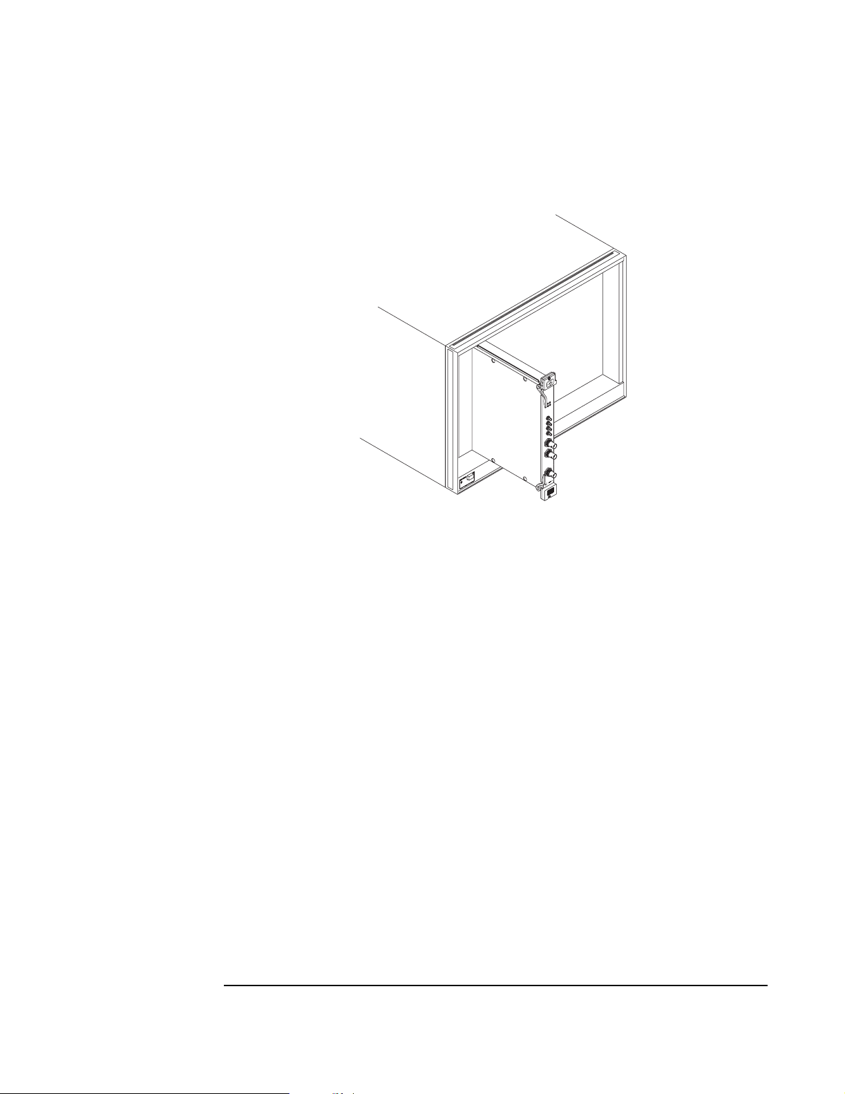
1. Set up your VXI mainframe. See the installation guide for your mainframe.
2. Select a slot in the VXI mainframe for the E1439 module.
The Agilent E1439D module’s local bus receives ECL-level data from the
module immediately to its left and outputs ECL-level data to the module
immediately to its right. Every module using the local bus is keyed to prevent
two modules from fitting next to each other unless they are compatible. If you
will be using the local bus, select adjacent slots immediately to the left of the
data-receiving module. If the VXI bus is used, maximum data rates will be
reduced but the module can be placed in any available slot.
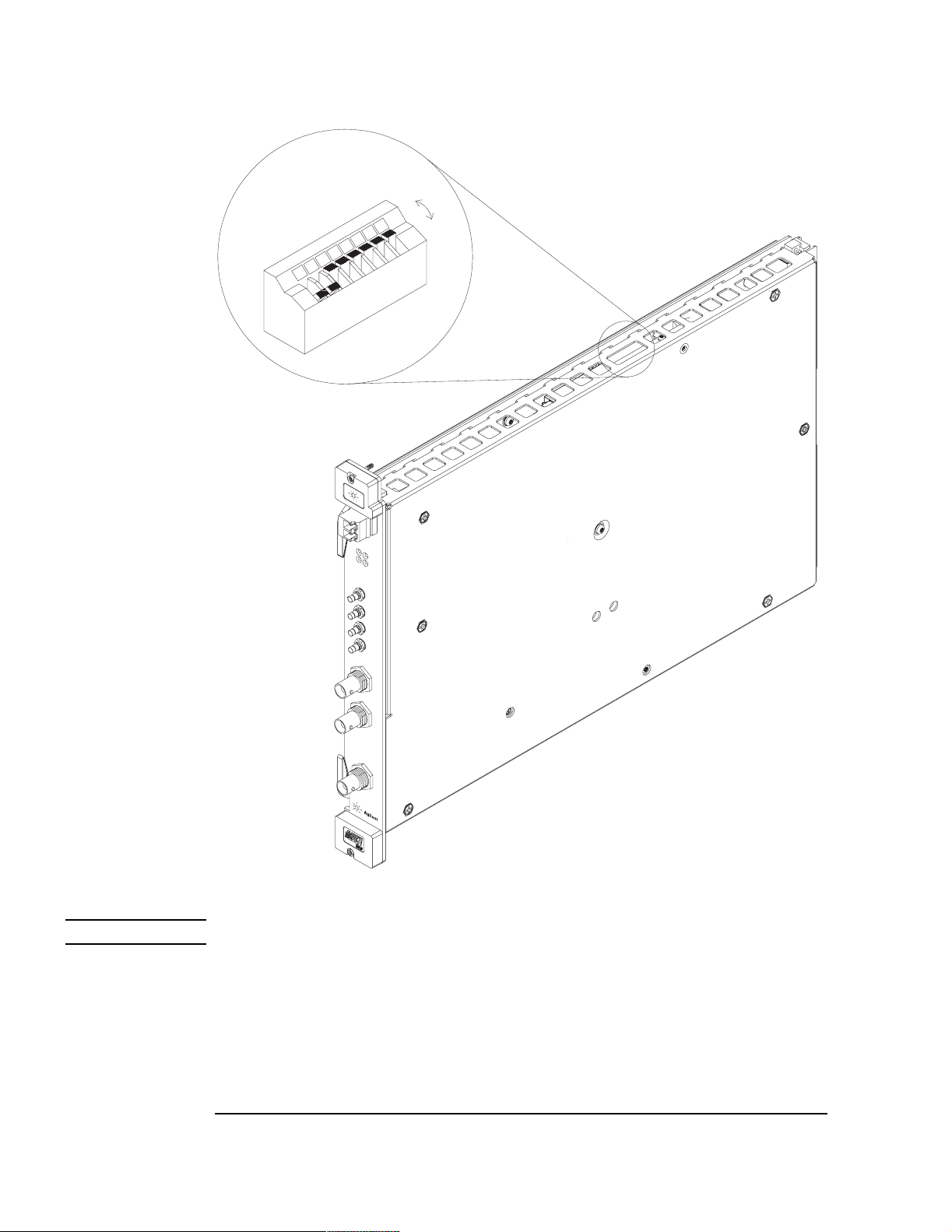
3. Using a small screwdriver or similar tool, set the logical address configuration switch on the E1439. (See the illustration on the next page.) Each module
in the system must have a unique logical address. The factory default setting
is 1100 0000 (192).
Note For optimal phase noise performance in multi-module systems it is recommended that the first
channel be an Agilent E1439C or D
optic transfers.
Note Multi-module systems may include multiple Agilent E1438s or Agilent E1439s but not a mixture
of the two types of modules.
1
As opposed to the older A or B models.
1
. The Agilent E1439C does not support local bus or fiber
3
Page 14
Installing the Agilent E1439
To install the Agilent E1439
Logical Address
0
1
4. Set the mainframe’s power switch to off (0).
Caution Installing or removing the module with power on may damage components in the module.
5. Place the module’s card edges (top and bottom) into the module guides in the
slot.
6. Slide the module into the mainframe until the module connects firmly with
the backplane connectors. Make sure the module slides in straight and that the
insertion/extraction levers are pressed parallel to the front panel.
4
Page 15
Installing the Agilent E1439
To install the Agilent E1439
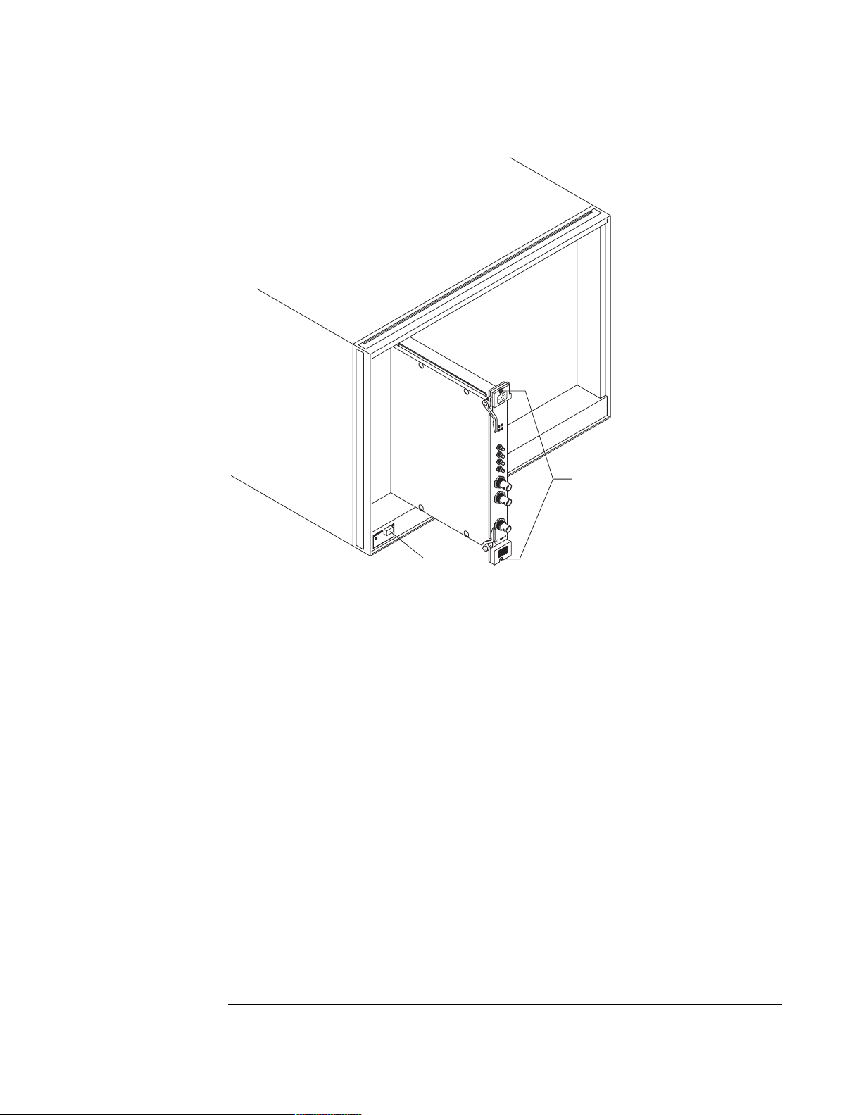
7. Attach the module’s front panel to the mainframe chassis using the module’s
captive mounting screws.
VXI Mainframe
E1438/
E1439
Slotted
Captive Screws
Power Switch
5
Page 16

Installing the Agilent E1439
To clean fiber optic connectors
To clean fiber optic connectors
The Agilent E1439D has a fiber optic serial FPDP (front panel data port). Since the data transmits
via light, the fiber optic connections must be clean. The following procedure describes how to
clean fiber optic connectors.
Caution Do not use any type of foam swab to clean optical fiber ends. Foam swabs can leave filmy
deposits on fiber ends.
1. Apply pure isopropyl alcohol to a clean lint-free cotton swab or lens paper.
Cotton swabs can be used as long as no cotton fibers remain on the fiber end after cleaning.
2. Clean the connector while avoiding the ends of the fiber.
3. Apply isopropyl alcohol to a new clean lint-free cotton swab or lens paper.
4. Clean the fiber end with the swab or lens paper.
Do not scrub during this initial cleaning because grit can be caught in the swab and become a
gouging element.
5. Immediately dry the fiber end with a clean, dry, lint-free cotton swab or lens paper.
6. Blow across the connector end face from a distance of 6 to 8 inches using filtered, dry,
compressed air. Aim the compressed air at a shallow angle to the fiber end face.
Nitrogen gas or compressed dust remover can also be used.
Caution Do not shake, tip, or invert compressed air canisters because this releases particles in the
can into the air. Refer to instructions provided on the compressed air canister.
7. As soon as the connector is dry, connect or cover it for later use.
Note To order multimode LC fiber optic cables, call Stratos Lightwave at (708) 867-9600
(http://www.stratoslightwave.com) or call Fiber Instrument at (800) 500-0347
(http://www.fisfiber.com).
6
Page 17

Installing the Agilent E1439
To store the module
To store the module
Store the module in a clean, dry, and static free environment.
For other requirements, see storage and transport restriction in “Technical Specifications”.
To transport the module
• Package the module using the original factory packaging or packaging identical to the factory packaging.
• If returning the module to Agilent Technologies for service, attach a tag
describing the following:
• Type of service required
• Return address
• Model number
• Full serial number
In any correspondence, refer to the module by model number and full serial number.
• Mark the container FRAGILE to ensure careful handling.
• If necessary to package the module in a container other than original packaging, observe the
following (use of other packaging is not recommended):
• Wrap the module in heavy paper or anti-static plastic.
• Protect the front panel with cardboard.
• Use a double-wall carton made of at least 200-pound test (32 ECT) material.
• Cushion the module to prevent damage. For example, several layers of plastic bubble
wrap is usually sufficient.
Caution Do not use styrene pellets in any shape as packing material for the module. The pellets do
not adequately cushion the module and do not prevent the module from shifting in the
carton. In addition, the pellets create static electricity that can damage electronic
components.
7
Page 18

Installing the Agilent E1439
To transport the module
8
Page 19

2
2 Getting Started with the Agilent E1439
Page 20

Getting Started with the Agilent E1439
Getting Started and Introduction
Getting Started and Introduction
This section helps you get your Agilent E1439 running and making simple measurements without
programming. It shows you how to install the software libraries and how to run the Soft Front
Panel program. It also introduces you to the example programs. The Host Interface Library is
available as a Windows Library that communicates with the hardware using VISA (Virtual
Instrument Software Architecture). VISA is the input-output standard upon which all the
VXIplug&play software components are based..
This section assumes you have already installed the module in the VXI mainframe as shown in
the previous chapter. It also assumes that you have installed a VXI interface according to the
manufacturer’s instructions.
Note Be sure to read the readme file for important up-to-date software installation information.
10
Page 21

Getting Started with the Agilent E1439
System Requirements
System Requirements (Microsoft Windows)
• A Pentium-class personal computer:
• Microsoft Windows 2000, or NT.
• One of the following interfaces:
• HP/Agilent FireWire −E8491B IEEE-1394 PC Link to VXI
• National Instruments PCI MXI-2
• Other VISA compliant VXI interface
• VISA (Virtual Instrument Software Architecture) library
• The computer must have a CD ROM drive for the installation media
System Requirements
• One of the following Web browsers:
• Microsoft Internet Explorer 4.0 or greater
• Netscape Navigator 4.08 or greater
11
Page 22

Getting Started with the Agilent E1439
To install the Windows VXIplug&play drivers
To install the Windows VXIplug&play drivers
This procedure assumes that you have already installed a VISA (Virtual Instrument Software
Architecture) library.
Note If you attempt to install the Windows VXIplug&play drivers without having installed a VISA
library you will receive a fatal error.
1. Insert the CD labeled: “Agilent E1439 VXI 70MHz IFADC with filters and
memory”
2. Run the program: drive:\windows\setup.exe
Where drive represents the drive containing the setup CD.
3. The setup program asks you to confirm or change the directory path. The
default directory path is recommended.
4. A dialog box asks if you want to install startup shortcuts
This creates a program group called “AGE1439” within the Vxipnp directory
that includes:
• A shortcut to run the Agilent E1439 Soft Front Panel
• A shortcut for the Agilent E1439 web-based online help file
• A shortcut for the PDF version of the Agilent E1439 User’s Guide
• A shortcut for the AGDSP web-based online help file
• Several shortcuts for example programs
• A shortcut for a readme file
5. A readme file may be displayed. If so, be sure to read it and follow the
instructions.
Updating firmware
Future updates will be distributed on the Web. To check your current revision run the Info Utility
or check Help/About in the Soft Front Panel program.
To check for new revisions access the Agilent Technologies Web page
http://www.agilent.com/ and search for "E1439".
Install the updated firmware using the firmware installation program—FirmwareInstall. This
program’s default location is drive:\vxipnp\win[95|NT]\age1439\firmware.Startthe
program, then use the "Select File" button to locate the firmware image you want to install. Enter
the VXI address of the instrument to be updated and click the "Update" button. The installation
will take one or two minutes. This program requires VISA to be installed on the host computer.
12
Page 23

Getting Started with the Agilent E1439
To use the Resource Manager
To use the Resource Manager
The Resource Manager is a program from your hardware interface manufacturer. It looks at the
VXI mainframe to determine what modules are installed. You need to run it every time you power
up. If you get the message: "VISUCCESS_DEVICE_NPRESENT" then run the Resource
Manager.
Before running the Agilent E1439 software make sure that your hardware is configured correctly
and that the Resource Manager runs successfully. Before using your measurement system, you
must set up all of its devices, including setting their addresses and local bus locations. No two
devices can have the same address. Usually addresses 0 and 1 are taken by the Resource Manager
and are not available.
For more information about the Resource Manager, see the documentation with your hardware
interface.
Note Most Resource Managers will recognize the manufacturer and model number of the
Agilent E1439 but if your interface requires that you enter this information manually, use the
following:
Manufacturer number: 4095 (Hex FFF)
Model number: 699 (Hex 2BB)
13
Page 24
Getting Started with the Agilent E1439
To use the program group (Windows)
To use the program group (Windows)
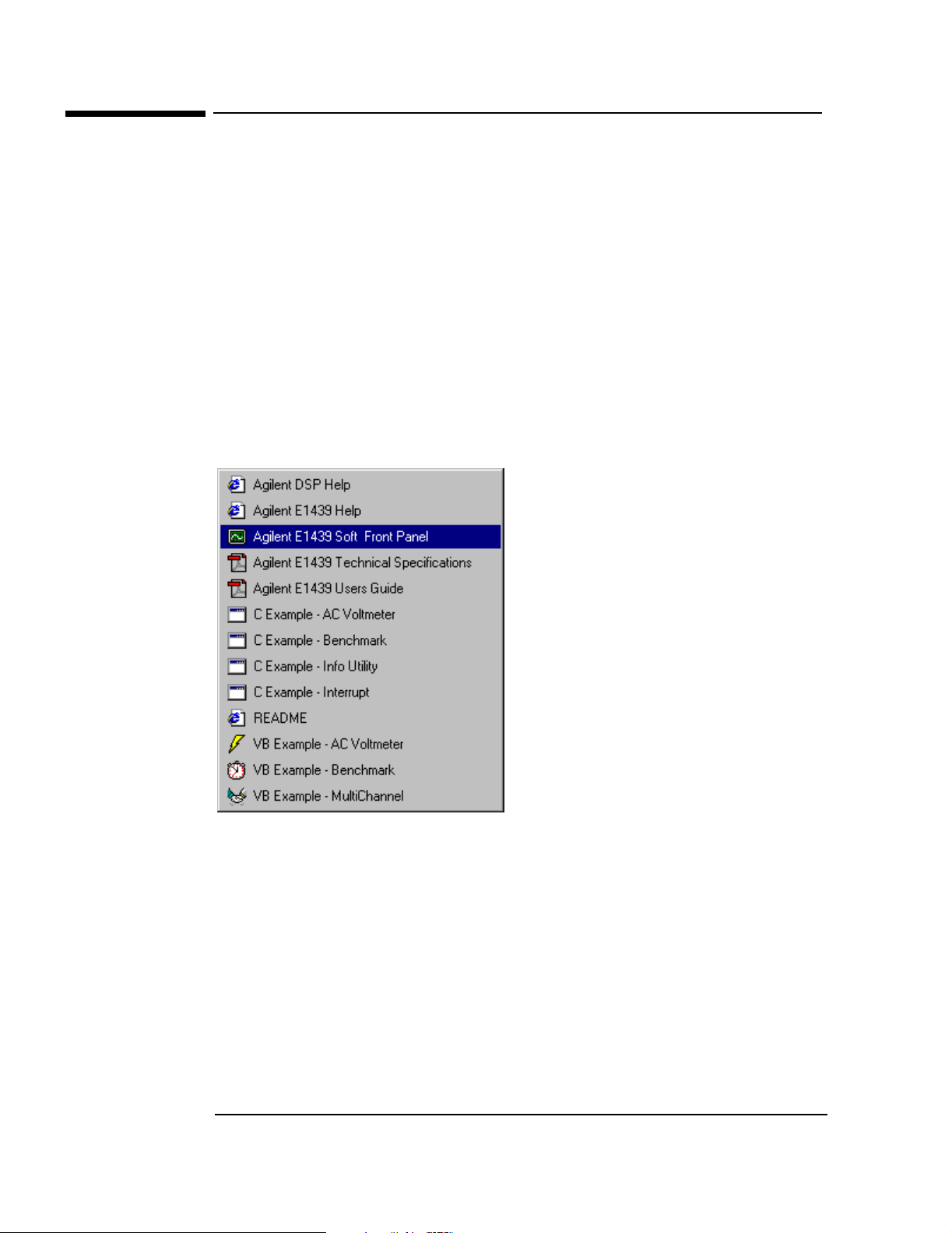
If you installed the program group using the default method during the installation procedure, you
have a shortcut for a program group similar the one below. Access it through the Start button:
Programs \ Vxipnp \ age1439
This program group contains shortcuts that access the Soft Front Panel program, the User’s
Guide, online help, and example programs. The following pages provide an overview of these
items.
If you did not install the program group, executable files for each of the items represented by
group shortcuts are available in the drive:\vxipnp directory and its subdirectories.
14
Page 25
Getting Started with the Agilent E1439
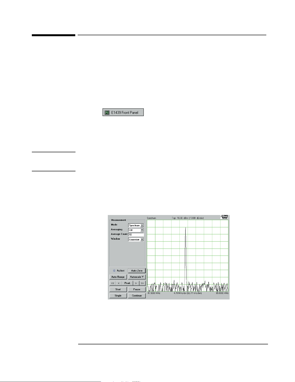
To use the VXIplug&play Soft Front Panel (SFP)
To use the VXIplug&play Soft Front Panel (SFP)
In a Windows environment, the Soft Front Panel is the best place to start to explore the
capabilities of the Agilent E1439. The Soft Front Panel is useful for checking your system to
make sure that it is installed correctly and that all of its parts are working. You can also use it to
make actual measurements, since it accesses most of the Agilent E1439’s functionality.
Select the shortcut in your program group to start the program. This
assumes you have already installed all required hardware and drivers (including VISA) and have
run the configurator and Resource Manager required by your hardware interface.
If prompted for the resource descriptor, use the default "VXI::192" unless the logical address of
the Agilent E1439 has been changed from its default setting of 192. If it has been changed, type
the appropriate logical address instead of 192, then press OK.
Note You can also run the Agilent E1439 Front Panel in a simulation mode without an Agilent E1439
module, a hardware interface, or VISA libraries by typing "sim" in place of the resource
descriptor.
The Agilent E1439 Front Panel Help, available from the Soft Front Panel Help menu, describes
the capability of the Soft Front Panel and has links to functions that control and define many of
the parameters.
The source files for this program are provided for you to use as sample code.
15
Page 26

Getting Started with the Agilent E1439
To use the example programs
To use the example programs
Several example programs are included that perform useful tasks and can serve as a basis for your
own programs. When you installed your Agilent E1439 Windows libraries and drivers using the
setup program or utility, you also installed executable and source code files for several useful
example programs. The programs demonstrate programming the module with "C", Microsoft
Visual Basic,
The executables for these examples require an Agilent E1439 and, for Windows, VXIplug&play
support; in other words, they will not run in simulation mode like the Agilent E1439 Soft Front
Panel program.
Shortcuts for the executables appear in the age1439 Windows program group if you added it
during setup.
In Windows environments, executable files and source code for the Microsoft Visual Basic
examples are installed in the drive:\vxipnp\win[95|NT]\age1439\vb directory. The "C" examples
are in the ...\age1439\msc\examples directory.
The group of programs described here may be supplemented with additional programs later,
which will be described in the online help or readme file.
ACVolts_32.exe
This is the simplest practical complete program using the Agilent E1439, and it functions like an
AC voltmeter. It is written in Visual Basic.
acvolts.exe
This is a console version of acvolts_32.exe, written in Microsoft Visual C++.
Benchmark_32.exe
This performance benchmark program is really more of a utility than an example, although source
code is provided. It allows users to measure data transfer rates and command processing times on
their system without having to write new code. The utility is written in Visual Basic.
bench.exe
This is a console version of Benchmark_32.exe, written in Microsoft Visual C++.
16
Page 27

Getting Started with the Agilent E1439
To use the example programs
multchan_32.exe
This example shows how to synchronize two modules to achieve simultaneous sampling, filter
decimation, and matched local oscillator phase. It is written in Visual Basic.
info.exe
This example shows how to retrieve option and revision information from an Agilent E1439, and
it doubles as a handy utility. It is written as a console program in Microsoft Visual C++.
interrupt.exe
This example shows how to set up and trap a VXI interrupt to indicate an error condition in the
Agilent E1439. It is written as a console program in Microsoft Visual C++.
17
Page 28

Getting Started with the Agilent E1439
To use the example programs
18
Page 29

3
3 Using the Agilent E1439
Page 30
Using the Agilent E1439
Agilent E1439 overview
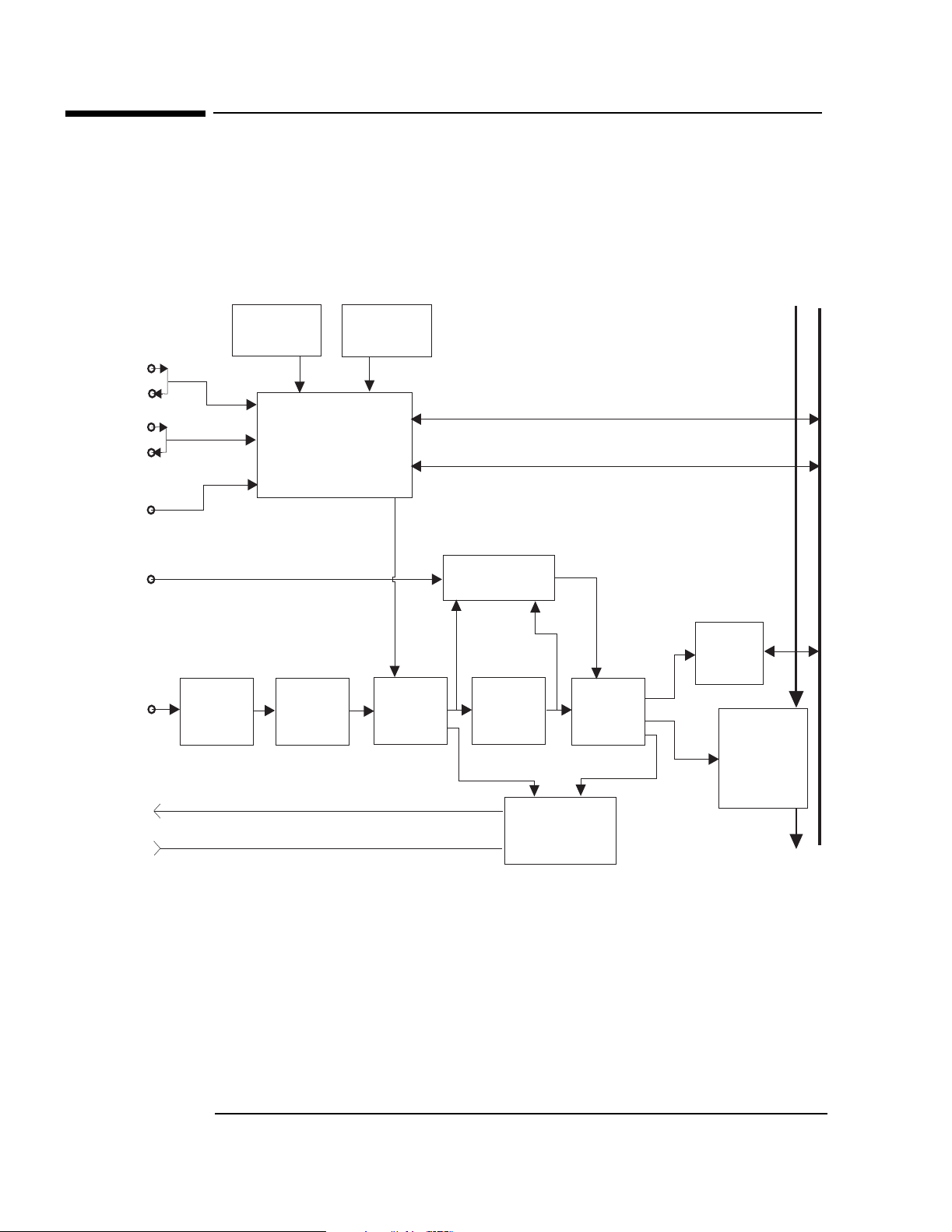
Agilent E1439 overview
Intermodule
clock
Intermodule
sync
Ext
Clock/Ref
Ext
Trigger
Analog
In
XMT
RCV
100 MHZ
VCXO
Attenuators
(E1439B/D only)
Clock
Generation
Anti-alias
Filter
102.4 MHz
VCXO
Sampling
ADC
Trigger
Detection
Zoom and
Decimation
Filtering
FPDP Interface
(E1439B/D only)
VXI CLOCK
VXI SYNC
Fiber Optic
FIFO
Memory
VXI Backplane
VXI bus
Interface
Local bus
Interface
(not present
in the E1439C)
20
Page 31
Using the Agilent E1439
Programming the Agilent E1439
Programming the Agilent E1439
The Agilent E1439 is shipped with software and documentation to support a broad set of choices
of controllers, I/O interfaces, programming languages, and operating systems. By virtue of its
compliance to the VXIplug&play standard, the E1439 is most easily controlled in an environment
conforming to one of the supported VXIplug&play frameworks. However, support is also
supplied for other common hardware and software environments. The relationship among the
various levels of programming is shown in the diagram below.
Windows & Visual Basic
C Programming
WIN
C-Function Library
Hardware Registers
Windows framework
The primary development environment supported by the E1439 is the VXIplug&play WINNT
framework specifications. It requires the following resources prior to the installation of the
E1439:
• An embedded or a stand-alone Pentium-class PC
• Microsoft Windows 2000, or NT
• VISA interface library
• VISA compatible hardware interface
• Microsoft Visual C++ and/or Microsoft Visual Basic development system.
Additional details on the WIN framework can be found in the VXIplug&play VPP-2 System
Frameworks Specification, Revision 2.0.
In addition to the C source code files, the E1439 includes compiled libraries, example programs,
an interactive soft front panel program, online help files, and an installation program. The
interactive soft front panel program allows the E1439 to be turned on, verified, and used for
simple tasks without writing any user programs.
21
Page 32

Using the Agilent E1439
Programming the Agilent E1439
Cprogramming
The E1439 is shipped with a source library of C-functions that can be called from user programs.
This elevates the interface above the register level so the programmer does not have to be
concerned with such things as register addresses and packing or splitting parameters into 16-bit
register lengths. The library includes ANSI compliant source code files with all machine
dependent code constrained to a single source file. By re-writing selected portions of the
machine.h file, the programmer can create and compile an E1439 library that is compatible with
virtually any development environment using the C language. The most common reason for rewriting machine.h is to accommodate I/O libraries other than VISA. In some cases, the library
may need merely to be re-compiled to target a different processor type for the host computer.
Porting the E1439 library to a different computer environment is likely to be a fairly straight
forward task. However, some of the higher level tools shipped with the E1439 may not be as
easily ported. The interactive soft front panel and some example programs include human
interfaces that depend on certain display and keyboard support which may be system dependent.
Although source code is included for these applications, porting them to a different environment
may present a greater problem than porting the library itself. The installation utilities are
specifically targeted to operate on the supported development environments and may not be
available in other environments.
22
Page 33

Using the Agilent E1439
The measurement loop
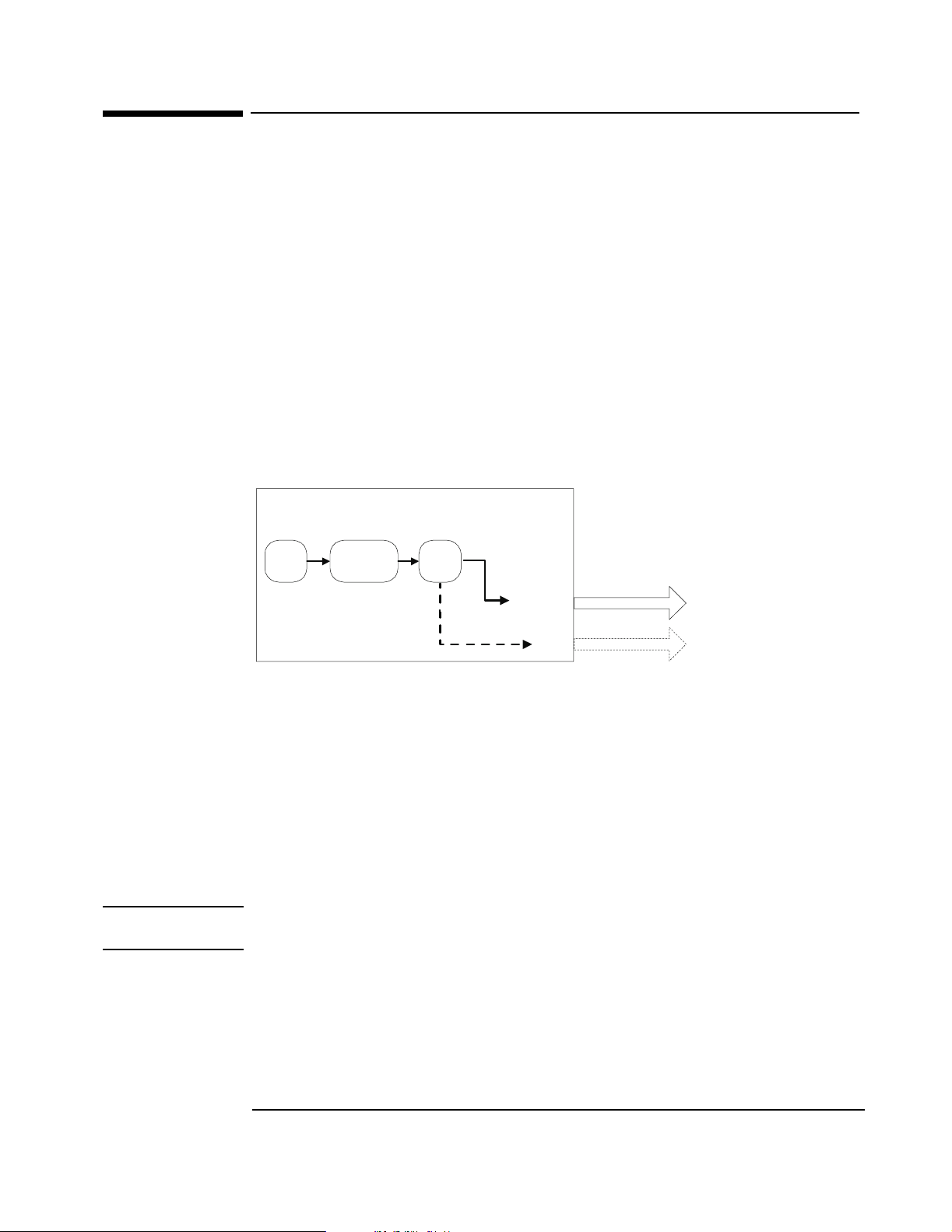
The measurement loop
The measurement loop progresses through four states. The transition from one state to the next is
tied to the transition of the Sync signal. The effect of the Sync signal is summarized in the
following diagram representing the four possible states of an Agilent E1439 module.
No data collected
Old data available
Release
(Block Mode)
Data collected and output
In the Idle state, the E1439 places no new data into the FIFO output buffer memory although
previously measured data is retained in the buffer memory and is available for output via the
VME (and also local bus, or fiber optic transmitter port on the E1439D). The module stays in the
Idle state until the Sync line is asserted.
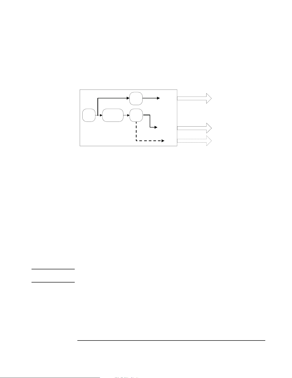
Upon entering the Arm state the E1439 clears old data. It remains in the Arm state until the Sync
signal is released. If an E1439 is programmed with a pre-trigger delay, it collects enough data
samples to satisfy this pre-trigger delay, and then releases the Sync line. If no pre-trigger delay
has been programmed, the module releases the Sync line immediately. When all E1439s in a
system have released the Sync line, the module moves to the Trigger state.
Upon entering the Trigg er state, an E1439 that is programmed with a pre-trigger delay continues
collecting data into the FIFO, discarding any data prior to the pre-trigger delay. An E1439
remains in the Trigger state until the Sync line is asserted. The Sync line may be asserted by a
direct command or by any E1439 that encounters a trigger condition and is programmed to assert
the Sync line. When the Sync signal is asserted, all modules synchronously move to the Measure
state.
IDLE
Measure
Assert
Assert
ARM
Trigger
New data collected
Old data cleared
Release
Data collected
Pre-trigger data cleared
In the Measure state, the E1439 continues collecting data and sends the data saved in the FIFO
memory to the selected I/O port, starting with the sample indicated by the trigger arrival, offset by
the number of samples specified by the trigger delay. This data transfer continues until all data has
been transferred or until the module meets the criteria for returning to the Idle state imposed by
block mode or continuous mode operation constraints.
23
Page 34

Using the Agilent E1439
The measurement loop
Modules programmed for block mode operation assert the Sync line until a complete block of
data, including any pre-programmed pre- or post-trigger delay, has been collected and is available
to the I/O port. The module then releases the Sync line. The module returns to the Idle state when
the block of data has been collected.
In continuous mode, a module releases sync immediately but moves to the Idle state only if
explicitly programmed to do so or if the FIFO data buffer overflows because data cannot be read
from the I/O port fast enough.
The measurement loop in multi-module systems
The following rules generally apply to transitions between states when multiple modules share a
Sync signal:
• If any one module asserts the Sync line, a synchronous state transition occurs for all modules
in a system.
• All modules in a system must have released the Sync line in order to bring about a
synchronous transition to Trigger state.
• In block mode, each module releases the Sync line after its block of data has been collected.
Immediately upon entering the Measure state in continuous mode, each module releases the
Sync line. It continues to collect and output data until it is programatically signaled to stop or
until the FIFO overflows. With the Sync line released it is then possible to change the center
frequency for one or multiple modules without interrupting the measurement. See
“Synchronizing changes in multi-module systems” on page 39.
• A module may be programmed explicitly to inhibit its transition to the Arm state despite Sync
transitions.
• In addition to controlling the progression through the four module states, the Sync signal is
used to synchronize the decimation counters and local oscillators of multiple E1439 modules.
24
Page 35

Using the Agilent E1439
Delay and phase in triggered measurements
Delay and phase in triggered measurements
It is important to note that the trigger delay is specified in terms of output samples. When using
the digital filters within the E1439 to reduce the sample rate, there are multiple ADC samples
corresponding to each output sample. In order to determine the relationship between the first
output sample of a block and the actual ADC sample where the trigger occurred, you must read
the actual delay from the module using age1439_trigger_delay_actual_get.
This relationship varies from block to block and is a function of the particular value of counters
within the digital filters at the time the trigger occurs. Thus the actual delay from the trigger event
is the delay from age1439_trigger_delay_get multiplied by 2
if filter decimation is used, or 2
value returned by age1439_trigger_delay_actual_get. The result is in periods of the ADC
sample clock. Special considerations apply in multi-module systems. See “Trigger and phase in
multi-module systems” on page 40.
(sigBw-1)
if filter decimation is off). From this value, subtract the
sigBw
(from age1439_filter_bw_get
When doing a zoomed measurement, it may also be helpful to know the phase of the digital LO at
the time the trigger occurred, since the LO is also running continuously and it has an arbitrary
phase relationship with the trigger event. age1439_trigger_phase_actual_get returns the phase
of the LO at the trigger point. The LO phase could be used in time domain averaging of blocks, or
other operations involving zoomed blocks of data, so that the varying phase of the LO can be
removed from the calculation.
The trigger_delay value is the time, measured in output samples, from the desired trigger point to
the start of the time record. The trigger_delay_actual value is the time, measured in input
samples, from the desired trigger point to the actual trigger point.
Start of
time record
Desired
trigger point
Actual
trigger point
signal
trigger_delay
trigger_delay_
actual
time
The following example illustrates how trigger_delay and trigger_delay_actual can be
combined. In this example:
filter_bw=4 (2.4 MHz span)
filter_decimate =1 (on)
25
Page 36

Using the Agilent E1439
Delay and phase in triggered measurements
trigger_delay = -2 (a pre-trigger delay of 2)
Because the filter_bw is 4 with decimation on, there are 16 input samples for every output sample
for a decimation rate of 2
.
4
trigger_delay_actual=0 (or 0/16=0 output samples)
desired trigger
trigger
signal
actual trigger
level
1
2
3
4
trigger_delay_actual=4 (or 4/16=1/4 output samples)
desired trigger
trigger
actual trigger
1
2
3
level
4
trigger_delay_actual=8 (or 8/16=1/2 output samples)
desired trigger
trigger
level
actual trigger
1
2
3
4
The phase returned is the phase of the LO at the actual trigger point, not the desired trigger point.
The following example illustrates how age1439_phase_actual_get might be used. In this
example, the input signal is a sine wave at a frequency of 4 MHz. The module is set up as follows:
frequency_center = 4.5 MHz
filter_bw = 4 (2.4 MHz span)
filter_decimate = 1 (on)
trigger_type = 1 (ADC trigger)
trigger_delay = -32 (a pre-trigger delay of 32)
trigger_adclevel = 0
data_type = 1 (complex)
After the measurement is completed, call age1439_delay_actual_get and age1439_phase_
actual_get. In this example, the values returned happened to be:
delay_actual = 16
phase_actual = 19697
26
Page 37

Using the Agilent E1439
Delay and phase in triggered measurements
Due to the pretrigger delay of 32, the desired trigger point would have been at the 32nd sample of
the time record. However, the delay_actual value of 16 indicates that the sample corresponding
to the actual trigger is number 32+16/2
(complex) sample, found via the atan2() function, is 159 degrees. The phase of the LO at this
sample is 19697*360/65536=108 degrees. Adding these together to get the corrected phase of the
input signal results in 267 degrees = -93 degrees, which is close to the expected phase of a sine
wave triggered at its zero-crossing, which would be -90 degrees.
4
or the 33rd sample. The measured phase of the 33rd
27
Page 38

Using the Agilent E1439
Magnitude trigger and magdwell time
Magnitude trigger and magdwell time
The magnitude trigger operates on the magnitude of a (possibly filtered) signal. For a real signal,
the magnitude is merely the absolute value of the signal. For a complex signal, the magnitude is
the square root of the sum of the squares of the real and imaginary parts of the signal.
Because the magnitude trigger can operate on the filtered signal, the trigger can be more selective
regarding what signals will cause a trigger than the ADC trigger. Only signals in the filter
bandwidth around the center frequency will be considered when determining when a trigger
occurs. Signals outside the filter's passband will be filtered out before the magnitude trigger
circuit and will not cause any triggers to occur.
The magnitude trigger's behavior can be modified by the magDwell time. The magDwell time is
the number of samples that a signal's magnitude must be low (i.e., below the magLevel threshold)
before the magnitude trigger circuit will recognize the signal as being low. This can facilitate
triggering off of a burst signal; for example, a tone burst or a TDMA burst. Due to the zero
crossings within the tone burst, the ADC trigger can not reliably trigger on the leading edge of the
burst. If you set the magDwell time longer than any potential drop outs within a burst and shorter
than the gap between bursts, the magnitude trigger can easily catch the leading edge of a tone
burst.
For a magnitude trigger with positive slope, the signal must be low for at least a magDwell
number of samples. After that, the module will trigger the next time the signal goes above the
magLevel threshold. For a negative slope, the module will trigger the first time that the signal is
low for at least a magDwell number of samples after being high. Note that in this case, the trigger
will occur a magDwell period of time after the end of the tone burst. You can use a negative
trigger delay to compensate for this and to capture the end of the tone burst.
A
B
C
D
Signal
Envelope
or
Level
Possible
Positive
Trigger
Points
Positive
Trigger
Point
Negative
Trigger
Point
magDwell times:
Output of magnitude
comparators
A. Time A is less than the magDwell time. The magnitude trigger does not recognize the
signal as being low.
B. Time B is longer than the magDwell time. The magnitude trigger does recognize the
signal as being low and a positive trigger may occur on the rising edge at the end of
B.
Time
High
Low
28
Page 39

Using the Agilent E1439
Magnitude trigger and magdwell time
C. Time C is less than the magDwell time. The magnitude trigger does not recognize the
signal as being low
D. Time D is longer than the magDwell time. The magnitude trigger does recognize the
signal as being low and a negative trigger may occur at the end of D.
In the example shown, the signal is below the threshold at A and C, but in both of these cases, the
signal is low for a time less than the magDwell time. Hence the magnitude trigger does not
recognize the signal as low and these do not cause any triggers. About half way through B, the
signal has remained low long enough so that the trigger recognizes the signal as low. After this, a
positive trigger would occur on the next rising edge of the signal's magnitude. A negative trigger
would occur at the end of D, a magDwell period of time after the falling edge.
29
Page 40

Using the Agilent E1439
Frequency and filtering
Frequency and filtering
The Agilent E1439’s center frequency is normally set at zero (baseband path) and 70 MHz for the
IF signal path. However, you may set the center frequency to a non-zero value in order to examine
a narrower span away from baseband (zoom measurement).The frequency band of interest,
represented by digitized time data samples from the ADC, is mixed with the E1439 digital LO, a
complex exponential, at the desired center frequency. As a result, the frequency band of interest in
the input signal is shifted to a complex signal centered around dc. See “Synchronizing changes in
multi-module systems” on page 39 for special considerations with respect to changing the center
frequency in multi-module systems.
The default filter for E1439 measurements is an analog anti-alias filter. However, you may further
isolate the frequency band of interest for more detailed analysis by using digital filtering. A
decimating digital filter simultaneously decreases the bandwidth of the signal and decreases the
sample rate. The built-in digital filters conform to the Nyquist sampling criterion, which
guarantees that the output sample rate may be reduced by the same factor as the signal bandwidth
reduction while still maintaining a complete representation of the underlying bandlimited signal.
For each octave step in bandwidth reduction (except for the first octave), the E1439 digital filters
automatically reduce the data rate by discarding alternate output samples. This process, called
decimation, results in an output sample rate that is nominally four times the signal bandwidth
whenever sigBw>0. This is still double the theoretical rate necessary to fully characterize the band
limited signal. However, because the digital filters do not have a perfectly abrupt cutoff, the
sample rate cannot be reduced to the theoretical limit without some aliasing of signals in the
transition frequency band of the filters. In many applications, this limited aliasing potential is not
important. For this reason you may optionally choose to apply a final factor-of-two decimation.
See the Technical Specifications for detailed information on the digital filter shapes.
The decimation process used to reduce the output sample rate is driven from a "decimation
counter" that keeps track of which samples to save and which ones to discard for each of the
octave bandwidth reduction filter stages. In multi-module systems where synchronous sampling is
required, the decimation counters in all the modules must be synchronous with each other. See
“Synchronizing changes in multi-module systems” on page 39.
30
Page 41

Using clock and sync
The following diagram shows the flow of clock and sync signals:
Using the Agilent E1439
Using clock and sync
EXT Clock/Ref
BNC
Intermodule Clock
SMB
Intermodule Sync
SMB
Font Panel Clock
SMB Clock Output
Reference Clock
Reference Prescaler
SYNC Clock
VXI Clock Output
ADC Clock
VCXO
VCXO Freq
ADC Divider
SYNC Output
SYNC Direction
VXI Clock
ADC Clock
VXI SYNC
31
Page 42

Using the Agilent E1439
Managing multiple modules
Managing multiple modules
Sharing Reference and Sync signals in multi-module systems
The Agilent E1439 supports synchronous operation among multiple E1439s by using a shared
ADC clock and Sync signal to drive all the modules in a system. The shared Sync signal is used to
synchronize critical operations including arming, triggering the beginning of data collection,
setting a common phase of the local oscillators for zoom operation, and forcing concurrent output
sample times when decimation is used. The Sync line transitions are constrained to not occur
during the critical (setup and hold) regions of the external reference. The reference operates at
1/38 of the internal ADC clock, typically 95 MHz for a E1439 module. The reference can be
either generated within the master module or an external reference can be fed into the master
module through a front panel BNC.
Note For optimal phase noise performance in multi-module systems it is recommended that the first
channel be an Agilent E1439C or D
optic transfers.
1
. The Agilent E1439C does not support local bus or fiber
Note Multi-module systems may include multiple Agilent E1438s or Agilent E1439s but not a mixture
of the two types of modules.
Clock distribution
When shared, the reference clock and sync lines are distributed among modules either on the VXI
backplane using the ECL Trigger lines, or on the front panel using the SMB Clock/Ref extender
connectors. When VXI backplane distribution is used with more than one VXI mainframe, the
front panel Intermodule Clock and Sync connectors can be used to distribute clock and Sync lines
from one mainframe to another.
Since the Sync transition timing relative to the reference input is critical, the module driving the
Sync line should ideally be the same one identified as the master. However, when using backplane
distribution, any E1439 in the same mainframe as the master can drive the Sync line.
When using the multi-sync mode of operation, the selection of front panel or backplane
distribution of reference and Sync signals involves the following considerations:
• Backplane distribution requires the use of the ECL Trigger lines on the backplane, which are
then unavailable to other modules.
• The overall time skew between the arrival of ADC clock edges is smaller when using
backplane distribution, particularly if the master (or buffer) module is physically located in
the center of the group of E1439 modules.
• Backplane distribution is more susceptible to pickup of jitter on the ADC clock from other
digital activity on the VXI backplane. The extent of this pickup depends on the mainframe and
on the other modules in the mainframe. One important step in reducing this pickup is to
disable, whenever possible, the 10 MHz VXI clock generated by the slot-0 controller.
1
As opposed to the older A or B models.
32
Page 43

Using the Agilent E1439
Managing multiple modules
• For backplane distribution make sure that all modules conform to VXI specification 1.4 or
later with regard to their attachment to the ECL Trigger lines. See the Agilent E1439
Technical Specifications for the clock jitter (phase noise) specification degradation using
backplane distribution.
• Front panel distribution requires the use of two short, equal length cables with SMB
connectors between modules. In addition, unused SMB connectors on modules being used for
front panel distribution must be terminated in 50 ohms.
The following diagrams show typical multi-module configurations and the clock setups that apply
to each module:
33
Page 44
Using the Agilent E1439
Managing multiple modules
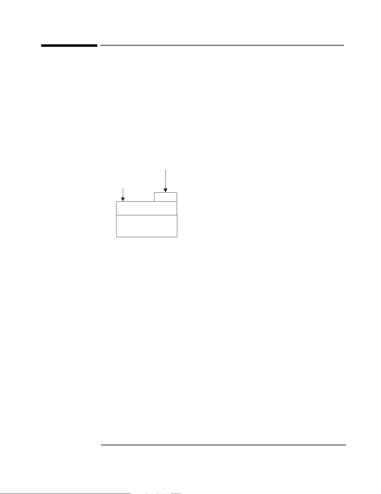
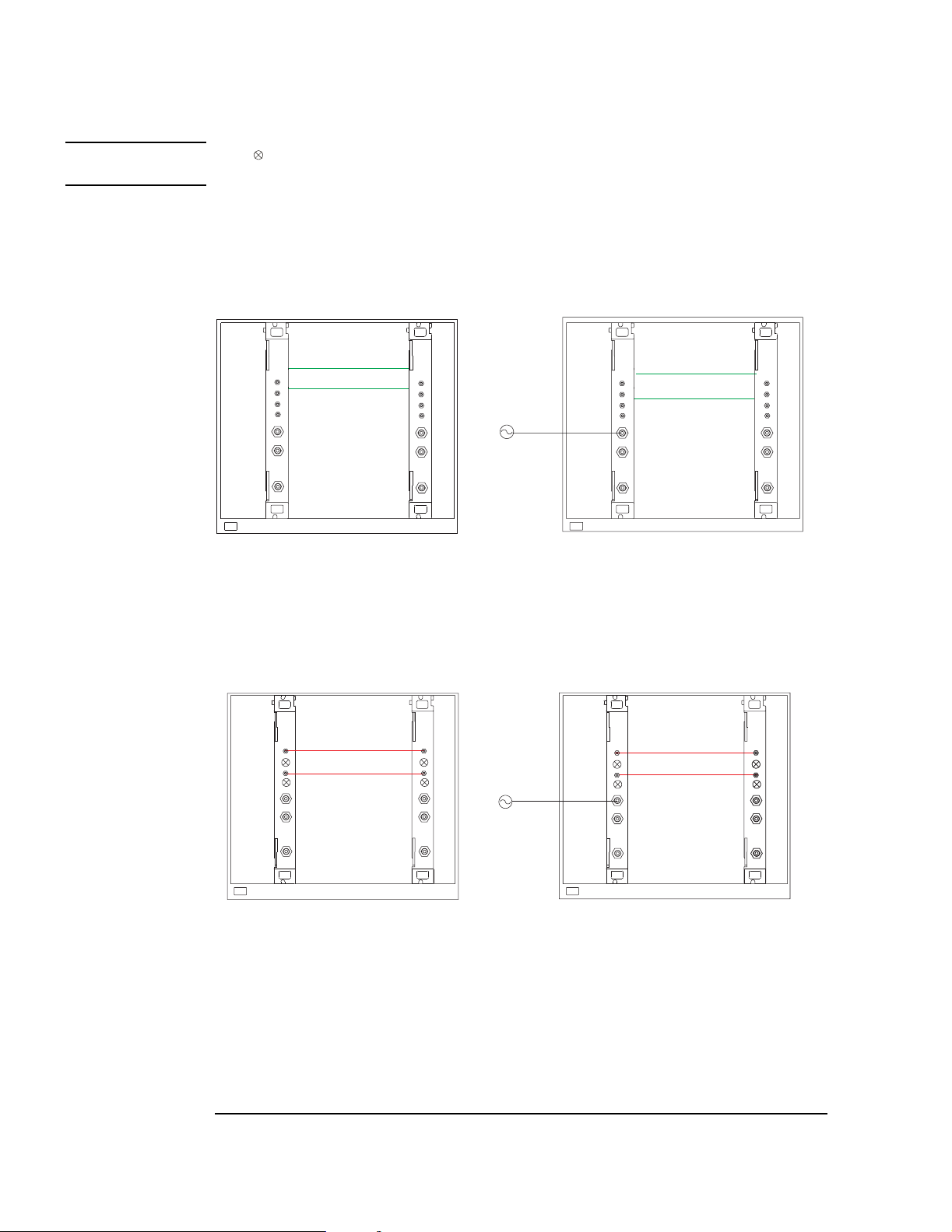
Managing multi-module systems
Note The symbol indicates a 50 ohm terminator, which is required on unused SMB connectors in
systems using front panel distribution
Module #1 - “Rear master,
internal reference” on page
82
Backplane
Slot 0
Controller
1
Module #2 - “Front slave,
phase locked to master” on
page 81
2
Internal clock and SYNC distribution
using VXI backplane ECL trigger lines.
Module #1 - “Front master,
internal reference” on page
80
Module #2 - “Front slave,
phase locked to master” on
page 81
Module #1 - “Front master,
phase locked to external
reference” on page 81
10 MHz
frequency
reference
External reference and SYNC distribution
Module #1 - “Front master,
phase locked to external
reference” on page 81
Module #2 - “Front slave,
phase locked to master” on
page 81
Backplane
Slot 0
Controller
1
2
using VXI backplane ECL trigger lines.
Module #2 - “Front slave,
phase locked to master” on
page 81
Slot 0
Controller
1
2
Internal clock and SYNC distribution using
front panel SMB clock and SYNC
extender connections.
34
10 MHz
frequency
reference
Slot 0
Controller
12
External reference and SYNC distribution using
front panel SMB clock and SYNC
extender connections.
Page 45

Using the Agilent E1439
l
Managing multiple modules
Module #1 - “Front slave,
phase locked to master” on
page 81
Module #2 - “Front master,
internal reference” on page
80
Slot 0
Controller
Sharing clock and SYNC among severa
modules via front panel distribution.
Managing multi-mainframe systems
Module #1 - “Front slave,
phase locked to master” on
page 81
Module #2 - “Front master,
internal reference” on page 80
Module # 3 - “Front slave,
phase locked to master” on
page 81
1
2
34
Module #3 - “Front slave,
phase locked to master” on
page 81
Module #4 - “Front slave,
phase locked to master” on
page 81
Module #4 - “Front slave,
phase locked to master” on
page 81
Slot 0
Controller
12
Slot 0
Controller
3
4
VXI Mainframe A VXI Mainframe B
Clock and SYNC distribution using front panel
extender connections within and between mainframes.
35
Page 46

Using the Agilent E1439
Managing multiple modules
Module #1 - “Front slave,
phase locked to master” on
page 81
Backplane
Slot 0
Controller
12
VXI Mainframe A VXI Mainframe B
Module #2 - “Send sync to
slave” on page 84
Module # 3 - “Receive sync
from master” on page 85
Slot 0
Controller
Backplane
34
Clock and SYNC distribution using front panel
extender connections between mainframes and
VXI backplane connections .within mainframes
Module #4 - “Front slave,
phase locked to master” on
page 81
36
Page 47

Using an external sample clock
All modules “Front sync, external sample clock, wired-OR sync” on page 83
Using the Agilent E1439
Managing multiple modules
Slot 0
Controller
Splitter
External sample clock
Splitter
User generated
external sync pulse
Sharing clock and SYNC among several
modules using external sample. Front panel distribution.
37
Page 48

Using the Agilent E1439
Managing multiple modules
All modules “Rear sync, external sample clock, wired-OR sync” on page 84
Backplane
Slot 0
Controller
Splitter
External sample clock
Splitter
User generated
external sync pulse
Sharing clock and SYNC among several
modules using external sample. Rear panel distribution.
38
Page 49

Using the Agilent E1439
Managing multiple modules
Synchronizing changes in multi-module systems
Multi-module systems require special treatment with respect to timing of frequency and filter
changes. Center frequency changes may involve synchronizing the local oscillators of all modules
in a system. Digital filter changes in multi-module systems require that the decimation counters
be synchronized.
Calling the following functions voids synchronized multi-module setups:
age1439_clock_setup and related low-level clock setup functions
age1439_clock_recover
age1439_input_autozero
age1439_input_range_auto
age1439_self_test
age1439_state_recall
Special considerations apply to the measurement loop. See “The measurement loop in multi-
module systems” on page 24.
Synchronous digital filter changes
In multi-module systems where synchronous sampling is required, the decimation counters in all
the modules must be synchronous with each other. This condition can be forced by preparing each
module in the system in advance. Any measurement in progress is terminated at this time and the
module is placed in the Idle state. After each module is prepared, the next sync line transition
causes the digital decimation counter to be reset and started at the same time. Once this is done,
the decimation counters stay synchronized as long as the same ADC clock is used.
If you also intend to change the center frequency along with the digital filters, you should
synchronize the digital filters first. Otherwise, the center frequency phase becomes
unsynchronized when the digital filters are changed.
Synchronous center frequency changes
In multi-module systems you may prepare each module in advance of a frequency change, then
perform the change synchronously by asserting the Sync line. This preserves the phase
relationship of the local oscillators for all modules in the system. Certain special considerations
apply to multi-module frequency changes:
• If all modules in a system are in the Idle state when the Sync line transition occurs, the LO
frequency is updated and the next measurement is armed.
• If all modules are in the measurement state in continuous mode when the Sync line transition
occurs, the LO frequency is synchronously updated, and the measurement continues.
• In continuous mode, care must be taken to assure that all modules are in the same state, either
the Idle state or the Measure state, before the Sync line transition occurs, otherwise some
modules re-arm while others continue the current measurement.
• In block mode, it is simplest to keep Forced Idle asserted during the Sync line transitions to
keep all the modules in the Idle state.
• If you also intend to change the digital filters along with the center frequency, you should
synchronize the digital filters first. Otherwise, the center frequency phase becomes nonsynchronized when the digital filters are changed.
39
Page 50

Using the Agilent E1439
Managing multiple modules
Trigger and phase in multi-module systems
When you use triggering in multiple modules, you do not need to measure phase differences
between two or more channels if the channels are set up identically in terms of digital filtering and
LO frequency, and the digital filters and LOs are correctly synchronized. Since the filters and LOs
are synced together, their actual trigger delays and LO phases are identical and will cancel out of
relative phase measurements. Any remaining delay should be less than 10ns between two
modules in the same mainframe.
Only the module that generates the trigger has knowledge of the delay between the trigger event
and the start of data collection. Therefore, if you need the actual delay from the trigger, you
should use the trigger delay correction from the module that generated the trigger. Likewise, you
should obtain the LO phase at the time of the trigger from the module that generated the trigger.
See “Delay and phase in triggered measurements” on page 25.
External sample synchronization in multi-module systems
There are two general instances where you might want to use an external sample clock in a system
with multiple E1439s:
• You wish to have the ADC's sample at a rate other than the 95 MHz clock supplied with the
E1439.
• You wish more precise simultaneous sampling than can be provided by the normal scheme
that uses the internal VCXOs within the modules locked together by a 2.5 MHz reference that
is distributed from module to module. By exercising care in matching the skew of the sample
clocks fed into each module, channel-to-channel group delays at low frequencies can be well
below a nanosecond.
Note External sample is specified only for use with baseband path.
To use external sample clocks with multiple modules and still perform synced measurements, you
need to use either the AGE1439_FRNT_SYNC_EXT_SAMP or AGE1439_REAR_SYNC_
EXT_SAMP clock setups (see “age1439_clock_setup” on page 78). These setups use the signal
that you feed into the Ext Clock/Ref BNC input of the E1439 as a sample clock for the ADC. A
counter within the E1439 generates two lower frequency clocks, one for the DSP circuitry and
one to clock the measurement SYNC signal between multiple modules. Since these clocks are
generated independently within each module, the counters in each module must be synced
together with a common externally generated signal in order to make properly synced and
triggered measurements involving multiple channels. You feed this "external sample sync" signal
into the External Trigger BNC and the module uses the signal to reset the counters to a known
phase.
The external sample sync signal should be generated on the falling edge of the external sample
clock, and fed into each module in the system by an identical length coax cable. Likewise, the
sample clock should be fed into each Ext Clock/Ref BNC by an identical length coax cable from a
common driver.
40
Page 51

Using the Agilent E1439
Managing multiple modules
Here is the sequence of operations:
1. Put all modules into either the AGE1439_REAR_SYNC_EXT_SAMP mode or the
AGE1439_FRNT_SYNC_EXT_SAMP mode with the age1439_clock_setup command.
2. Issue the age1439_ext_sample_sync (AGE1439_EXT_SAMPLE_SYNC_ENABLE)
command to reset the counters within all the E1439s.
3. Generate the external sample sync pulse simultaneously into all modules. One way to do
this is to use one of the VXI TTLTRG lines and reclock the signal with the falling edge of
the sample clock. Note: If you are using an E1439A module with a serial number lower
than US41140000, you will need some user supplied hardware to convert TTLTRG to
ECL because older E1439As do not support TTL trigger.
4. Issue the age1439_clock_recover command to all modules since the DSP clock was
interrupted between the age1439_ext_sample_sync command and the external sync
signal on the Trigger input.
5. Sync the digital filters:
• Force all modules to idle (age1439_meas_control).
•Sendtheage1439_filter_sync command to all modules.
• Assert and release the sync line from the master module (age1439_meas_control).
• Release all modules from idle (age1439_meas_control).
6. Sync the digital local oscillators:
• Force all modules to idle (age1439_meas_control).
• Set all module frequencies to zero (age1439_frequency_center).
• Assert and release system Sync (age1439_meas_control).
• Set the LO frequencies to the desired ones (age1439_frequency_center).
• Toggle system Sync again to synchronously set the LO frequencies (age1439_meas_
control).
• Finally release all modules from idle (age1439_meas_control).
7. Now you may take a measurement:
•Issueanage1439_meas_start.
• Retrieve data from the modules when valid.
In the event that you do not supply a synchronizing signal in a reasonable length of time (or you
change your mind about it), the DSP clock can be restored by issuing age1439_ext_sample_sync
(AGE1439_EXT_SAMP_SYNC_CANCEL) followed by an age1439_clock_recover.
You should not need to perform the external sample sync operation again unless the external
clocks are interrupted or the clock setup changed.
See also the diagrams earlier in this section that show the physical setup. All the functions
mentioned above are described in “Functions listed alphabetically” in chapter 4.
41
Page 52

Using the Agilent E1439
Transferring data
Transferring data
You can transfer data from the Agilent E1439C or D via the VMEbus. With the Agilent E1439D
you can also transfer data via the Local Bus and via a fiber optic interface.
• The VMEbus is the universal data bus for VXI architecture. It provides flexibility and
versatility in transferring data. Transfers over the VMEbus are 16 bits or 32 bits wide.
• The Local Bus on the Agilent E1439D supports faster transfer rates than the VMEbus. For
example, if you are transferring data from the Agilent E1439D to the Agilent E9821, the
Local Bus provides a direct pipeline to the Agilent E9821’s DSPs.
Using the Local Bus, you can transfer data in the background while processing data in a
signal-processing module. All Local Bus data transfers originate in the Agilent E1439D and
move towards a signal processing module to the right of the Agilent E1439D. If other
modules generate data to the left of the input module, the Agilent E1439D passes the data to
its right and inserts or appends its own data at the beginning or end of the frame.
• The fiber optic interface, available on the Agilent E1439D, provides data rates greater than
200 Mbytes/second. It can transmit filtered or unfiltered data, copy data from its receiver to its
transmitter, or append data to copied data.
42
Page 53

Using the Agilent E1439
Fiber Optic Interface
Fiber Optic Interface
The E1439D provides a fiber optic interface that can transmit continuous full bandwidth data
from the internal A/D converter. In addition, it can stream data from multiple synchronized
modules operating at lower bandwidths onto a single fiber optic channel. An optical receiver can
then simultaneously analyze data collected at different frequencies and bandwidths.
The E1439D fiber optic interface uses a serial data stream protocol providing high data
throughput and low latency characteristics. This protocol is intended to be compatible with the
Serial Front Panel Data Port Draft Standard (VITA 17.1, draft 0.5 dated February 26, 2001)
currently under development by the VITA Standards Organization (http://www.vita.com). VITA
17.1 is not yet approved and manufacturers are not yet permitted to claim conformance to the
draft standard. However, laboratory testing at Agilent Technologies has demonstrated
interoperability of the E1439D with fiber optic products from other manufacturers that also intend
to support the draft standard. These products include Systran Simplex Link Protocol products,
such as the SL100 and SL240, and Mercury Computer products, such as the RINOJ-F RACEway
I/O daughter card.
The following overview supplies the basic concepts required to use all the supported features. For
details, see the descriptions of the API functions.
43
Page 54

Using the Agilent E1439
Fiber Optic Interface
Fiber Frames
Data is transmitted over the fiber interface in a series of fiber frames. Each fiber frame is
composed of a series of 32-bit values, which encode to 40 bits. Each 32-bit value can either be
data or an ordered set. Data and ordered sets are strung together to make the three types of fiber
frames—Data Frame, BOF, and EOE. The Data Frame transmits 0 to 512 32-bit data words. The
exact amount of data that is sent depends on the amount of data that is available when the fiber
interface is ready to send the Data Frame. BOF (Beginning Of Frame) is a synchronizing event
that can be sent just prior to the start of data transmission. EOE (End Of Epoch) is a synchronizing
event that contains the last 4 data bytes in an epoch. An epoch is composed of one or more Data
Frames followed by an EOE. The following shows the ordered sets and data that make up the
three fiber frames:
Data Frame (Normal Data Fiber Frame)
1
IDLE
BOF (Sync Without Data Fiber Frame)
1
IDLE
EOE (Sync with Data Fiber Frame)
9
SWDV
SOF
SOF
SOF
2
2
2
0 to 512 data words
No data
Last 4 data bytes in epoch
3
10
CRC
CRC
CRC
4
FEOF
4
MEOF
4
MEOF8SEOF
5
8
SEOF
SEOF
6
6
6
GO/STOP
GO/STOP
GO/STOP
7
7
7
1. Pad for Data Frame or BOF
2. Start Of Frame, framing event that embeds PIO1, PIO2, and DIR
3. 32 bit or 4 Byte words, maximum 2048 Bytes
4. Cyclic Redundancy Check, optional
5. Frame End Of Frame, end of Data Frame
6. Status End Of Frame, embeds FIFO OV and NRDY
7. Flow controls
8. Mark End Of Frame, end of BOF and EOE
9. Sync With Data Valid, start of EOE
10.4 bytes, exactly
Control Signals
PIO1, PIO2, DIR, and NRDY are FPDP (front panel data port) control signals. These signals can
be defined by another product or you can define their meaning and application.
When an overflow condition in the transmit FIFO occurs, the E1439D asserts FIFO OV indicating
a loss of data. This may occur in Append fiber mode if the available fiber bandwidth capability is
exceeded.
If flow control is enabled, the E1439D responds to the STOP and GO signals. See “Generate” on
page 48 for details.
44
Page 55
Using the Agilent E1439
Fiber Optic Interface
Fiber Modes
The E1439D’s fiber interface can operate in five different modes:
• “Off” on page 45
• “Copy” on page 46
• “Raw” on page 47
• “Generate” on page 48
• “Append” on page 50
Off
The Off fiber mode disables the fiber transmitter but allows the fiber receiver to read control
signals. Normal data collection and filtering continues, and the data port selection determines
whether data is sent to the local bus (Agilent E1439D only) or read from the FIFO via the VME
bus. See the following illustration.
E1438D / E1439D
Fiber TXFiber RX
ADC
DIGITAL
FILTERS
FIFO
VME BUS
LBUS
Fiber Interface Setup
Fiber Mode Off
Rate setting ignored
BOF setting ignored
CRC setting ignored
Flow Control setting ignored
Epoch Generate setting ignored
Epoch Size setting ignored
Note Setting the data port to Fiber while in the Off fiber mode causes the data FIFO to fill up with
filtered ADC data, which then causes data collection to stop.
45
Page 56

Using the Agilent E1439
Fiber Optic Interface
Copy
The Copy fiber mode copies optical data from its fiber receiver to its fiber transmitter without
adding any data. Normal data collection and filtering continues, and the data port selection
determines whether data is sent to the local bus (Agilent E1439D only) or read from the FIFO via
the VME bus. Copy is the default fiber mode after power-on or reset. See the following
illustration.
E1438D / E1439D
ADC
DIGITAL
FILTERS
1KB
FIFO
FIFO
Fiber TXFiber RX
VME BUS
LBUS
Fiber Interface Setup
Fiber Mode Copy
Rate 106 or 250 MBs
BOF setting ignored
CRC must match incoming signal
Flow Control setting ignored
Epoch Generate setting ignored
Epoch Size setting ignored
Note Setting the data port to Fiber while in the Copy fiber mode results in an invalid instrument state.
46
Page 57
Using the Agilent E1439
Fiber Optic Interface
Raw
The Raw fiber mode transmits raw (i.e., unprocessed, full bandwidth) ADC data over the fiber
interface. At the same time that the raw data is transmitted over the fiber interface, filtered ADC
data can be sent over the local bus (Agilent E1439D only) or read from the FIFO via the VME
bus. After selecting Raw, optical data transmission starts at the trigger event and is not affected by
trigger delays or data delays. The raw data transmission continues even after the measurement is
complete. Changing the fiber mode stops data transmission. See the following illustration.
E1438D / E1439D
ADC
DIGITAL
FILTERS
Fiber Interface Setup
Fiber Mode Raw
Rate
BOF Optional
CRC
Flow Control Optional
Epoch Generate Optional
Epoch Size Divisible by 4
1
10 6
or 250 MBs
2
ON
1. Only with external sample. Internal sample generates data too fast for
this rate.
2. Some receivers may
require CRC to be off
for compatibility
1KB
FIFO
FIFO
Fiber TXFiber RX
VME BUS
LBUS
Note Setting the data port to Fiber while in the Raw fiber mode results in an invalid instrument state
because raw and filtered data cannot both be sent over the fiber interface at the same time.
47
Page 58

Using the Agilent E1439
Fiber Optic Interface
Generate
If flow control is off, Generate fiber mode transmits filtered ADC data over the fiber interface as
soon as data is available. ADC data is not available via any other data port and received optical
data is ignored. The following illustration shows an E1439D transmitting data when flow control
is turned off.
E1438D / E1439D
Fiber RX
ADC
DIGITAL
FILTERS
Fiber Interface Setup
Fiber Mode Generate
Rate 106 or 250 MBs
BOF Optional
CRC
ON
1
Flow Control OFF
Epoch Generate Optional
Epoch Size Divisible by 4
1. Some receivers may
require CRC to be off
for compatibility
Fiber TX
1KB
FIFO
FIFO
VME BUS
LBUS
48
Page 59

Using the Agilent E1439
Fiber Optic Interface
If flow control is on and the fiber receiver is capable of generating flow control signals, Generate
fiber mode transmits filtered ADC data after the fiber receiver indicates that it is ready and a
complete data block is ready to be transmitted. ADC data is not available via any other data port
and received optical data, other than the flow control signals, is ignored. The following
illustration shows an E1439D transmitting data to a fiber receiver when flow control is on.
Fiber ReceiverE1438D / E1439D
ADC
DIGITAL
FILTERS
Fiber Interface Setup
Mode Generate
Rate 106 or 250 MBs
BOF Optional
CRC ON
Flow Control No Copy
Epoch Generate Optional
Epoch Size Divisible by 4
FIFO
1KB
FIFO
Fiber TXFiber RX
VME BUS
LBUS
Fiber
RX
DATA
Fiber
TX
FLOW
CONTROL
Processing
49
Page 60

Using the Agilent E1439
Fiber Optic Interface
Append
The Append fiber mode copies optical data from its fiber receiver to its fiber transmitter and
appends its own filtered ADC data. This mode is required in an optical fiber append chain. For
the first module in an append chain, set the fiber mode to Generate, BOF to ON, and Epoch
Generate to ON. The module generates data epochs in the standard fashion and a BOF is sent after
each epoch. For all modules after the first, set fiber mode to Append, BOF to ON, and Epoch
Generate to ON. Each module copies received data to its transmitter output until a BOF is
received. The module then sends one epoch of filtered data from its ADC (if at least one block is
available), followed by a BOF.
In block data mode, the data from a single trigger is transmitted. Subsequent triggers should not
be generated faster than the data can be transmitted.
In continuous data mode, the generated data must not exceed the available fiber bandwidth,
allowing the data to be merged without data loss from a FIFO overrun. Therefore, you must
reduce the generated sample rate using either an external sample clock operating at a slower rate
or data decimation. If you use an external sample clock operating at a slower rate, epoch size must
be 1024 bytes (a larger epoch size causes a FIFO overrun resulting in a loss of data, and a smaller
epoch size increases overhead reducing the available bandwidth). The available bandwidth is then
about 101 MBytes/second or 238 MBytes/second. If you use data decimation, an epoch size of
approximately 2048 bytes provides the maximum available bandwidth.
Note Epoch size and block size must be equal (in bytes). Since block size is in samples, you can
multiply block size by the number of bytes per sample to determine the equivalent epoch size.
Conversely, you can divide the epoch size by the number of bytes per sample to determine the
equivalent block size. Real 12-bit data contains 2 bytes per sample, complex 12-bit data and real
24-bit data contains 4 bytes per sample, and complex 24-bit data contains 8 bytes per sample.
50
Page 61

The following shows two E1439D modules in an append chain transmitting data to a fiber
receiver when flow control is off.
E1438D / E1439D Fiber ReceiverE1438D / E1439D
Using the Agilent E1439
Fiber Optic Interface
Fiber RX
ADC
DIGITAL
FILTERS
Fiber
RX
DATA
Processing
FIFO
1KB
FIFO
Fiber TX
VME BUS
LBUS
ADC
DIGITAL
FILTERS
1KB
FIFO
FIFO
Fiber TXFiber RX
1KB
FIFO
VME BUS
LBUS
Fiber Interface Setup
First E1439D in chain Next E1439D in chain
Mode Generate Mode Append
Rate 106 or 250 MBs Rate same as module to left
BOF ON BOF
ON
1
CRC ON CRC ON
Flow Control OFF Flow Control OFF
Epoch Generate ON Epoch Generate ON
Epoch Size Divisible by 4; must match blocksize Epoch Size Divisible by 4; must match blocksize
1. The final module in an append chain may require BOF to be Off for compatibility with data receivers that cannot process BOFs.
Fiber
TX
51
Page 62
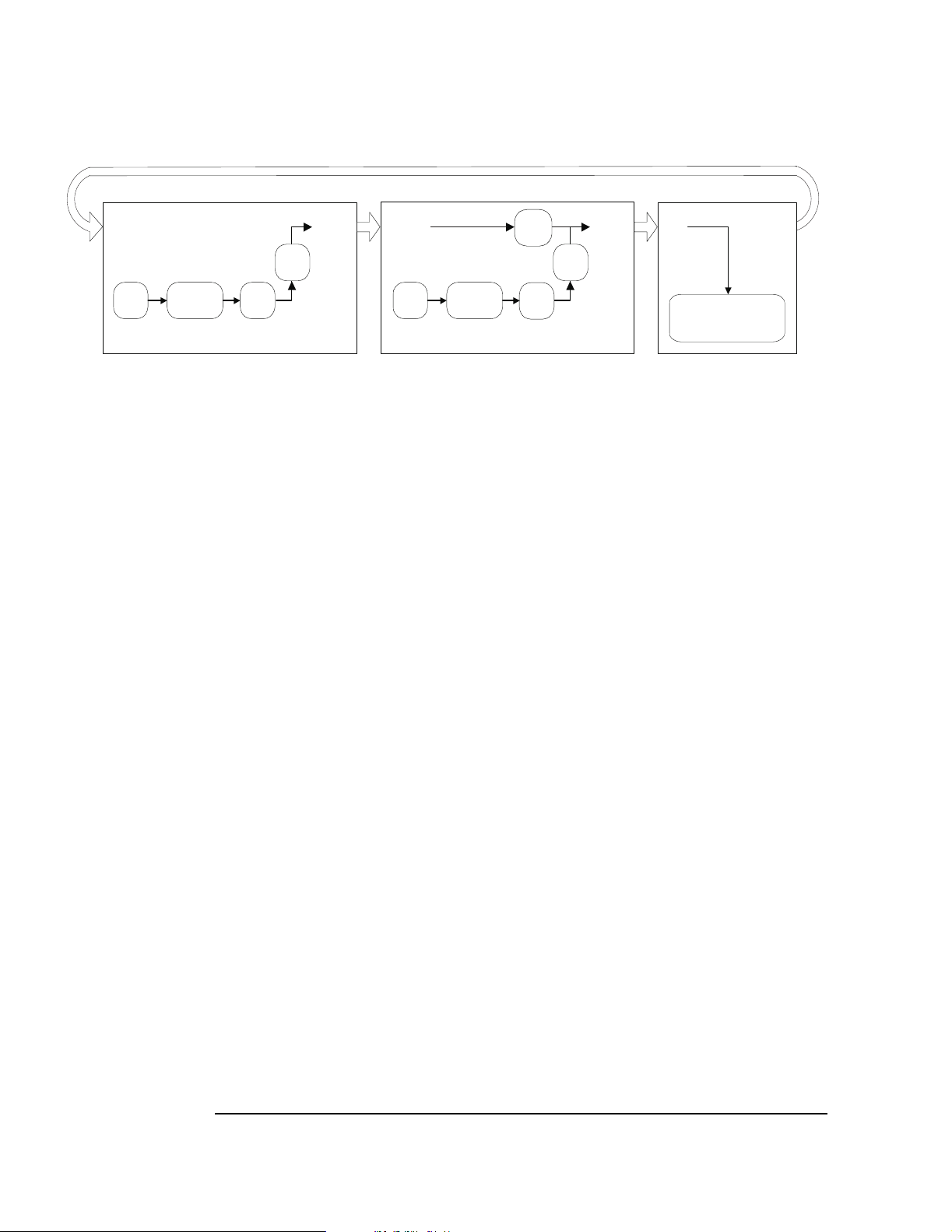
Using the Agilent E1439
Fiber Optic Interface
The following shows two E1439D modules in an append chain transmitting data to a fiber
receiver when flow control is on.
E1438D / E1439D Fiber ReceiverE1438D / E1439D
Fiber RX
ADC
Fiber
RX
DIGITAL
FILTERS
FIFO
1KB
FIFO
Fiber TX
VME BUS
LBUS
ADC
DIGITAL
FILTERS
1KB
FIFO
FIFO
1KB
FIFO
Fiber TXFiber RX
VME BUS
LBUS
Fiber Interface Setup
First E1439D in chain Next E1439D in chain
Mode Generate Mode Append
Rate 106 or 250 MBs Rate same as module to left
BOF ON BOF
ON
1
CRC ON CRC ON
Flow Control Copy Flow Control
No Copy
2
Epoch Generate ON Epoch Generate ON
Epoch Size Divisible by 4; must match blocksize Epoch Size Divisible by 4; must match blocksize
1. The final module in an append chain may require BOF to be Off for compatibility with data receivers that cannot process BOFs.
2. Set intermediate modules to Copy and the last module to No Copy.
Fiber
TX
DATA
Processing
52
Page 63

4
4 Agilent E1439 Programmer's Reference
Page 64

Agilent E1439 Programmer's Reference
Introduction
Introduction
The programmer’s reference is presented as a set of VXIplug&play functions since this is the
primary targeted environment. However, when you performed the setup for the Agilent E1439,
drivers were installed to support various programming environments as described in
“Programming the Agilent E1439” in chapter 3.
The function descriptions in the programmer’s reference are valid for all environments. Be sure to
follow the instructions in “Getting Started and Introduction” in chapter 2 to assure proper
installation and to become familiar with the capabilities of your Agilent E1439 software in
various programming environments. You should find the example programs particularly helpful
for programming in various environments.
Many of the function descriptions in the programming reference include several related functions.
You may use the primary function to set all related parameters or you may use the other functions
within the group to set or query a single parameter.
Parameter variables are presented as alphanumeric values which are descriptive and easy to
remember. However, for faster programming you may use the numeric equivalents for the
parameter variables listed at the end of this section.
54
Page 65

Agilent E1439 Programmer's Reference
Functions listed by class
Functions listed by class
Component Capability Subclass Function Name
INITIALIZE & CLOSE age1439_init (on page 132)
age1439_close (on page 86)
MEASURE READ INITIATE age1439_meas_control (on page 151)
age1439_meas_init (on page 154)
age1439_meas_start (on page 155)
age1439_meas_status_get (on page 156)
age1439_wait (on page 189)
MEASURE READ FETCH age1439_read (on page 159)
age1439_read64 (on page 159)
age1439_read_raw (on page 162)
MEASURE CONFIGURE age1439_clock_fs (on page 76)
age1439_clock_fs_get (on page 76)
age1439_clock_recover (on page 77)
age1439_clock_setup (on page 78)
age1439_clock_setup_get (on page 78)
age1439_combo_setup (on page 87)
age1439_data_memsize_get (on page 88)
age1439_data_scale_get (on page 89)
age1439_data_setup (on page 90)
age1439_ext_sample_sync (on page 104)
age1439_ext_sample_sync_get (on page 104)
age1439_filter_setup (on page 120)
age1439_frequency_setup (on page 128)
age1439_input_autozero (on page 134)
age1439_input_range_auto (on page 137)
age1439_input_setup (on page 141)
age1439_input_range_convert (on page 138)6
age1439_trigger_setup (on page 183)
MEASURE CONFIGURE LOW LEVEL age1439_adc_clock (on page 72)
age1439_adc_clock_get (on page 72)
age1439_adc_divider (on page 73)
age1439_adc_divider_get (on page 73)
55
Page 66

Agilent E1439 Programmer's Reference
Functions listed by class
Component Capability Subclass Function Name
age1439_data_blocksize (on page 90)
age1439_data_blocksize_get (on page 90)
age1439_data_delay (on page 90)
age1439_data_delay_get (on page 90)
age1439_data_mode (on page 90)
age1439_data_mode_get (on page 90)
age1439_data_port (on page 90)
age1439_data_port_get (on page 90)
age1439_data_resolution (on page 90)
age1439_data_resolution_get (on page 90)
age1439_data_spectral_order (on page 90)
age1439_data_spectral_order_get (on page 90)
age1439_data_type (on page 90)
age1439_data_type_get (on page 90)
age1439_data_xfersize (on page 96)
age1439_data_xfersize_get (on page 96)
age1439_filter_bw (on page 120)
age1439_filter_bw_get (on page 120)
age1439_filter_decimate (on page 120)
age1439_filter_decimate_get (on page 120)
age1439_filter_sync (on page 123)
age1439_frequency_center (on page 128)
age1439_frequency_center_get (on page 128)
age1439_frequency_center_raw (on page 125)
age1439_frequency_center_raw_compute (on
page 127)
age1439_frequency_center_raw_get (on page 125)
age1439_frequency_cmplxdc (on page 128)
age1439_frequency_cmplxdc_get (on page 128)
age1439_frequency_sync (on page 128)
age1439_frequency_sync_get (on page 128)
age1439_front_panel_clock_input (on page 131)
age1439_front_panel_clock_input_get (on page 131)
age1439_input_alias_filter (on page 141)
age1439_input_alias_filter_get (on page 141)
age1439_input_autozero (on page 134)
age1439_input_coupling (on page 141)
age1439_input_coupling_get (on page 141)
age1439_input_offset (on page 135)
age1439_input_offset_get (on page 135)
56
Page 67

Agilent E1439 Programmer's Reference
Functions listed by class
Component Capability Subclass Function Name
age1439_input_offset_save (on page 136)
age1439_input_range (on page 141)
age1439_input_range_get (on page 141)
age1439_input_signal (on page 141)
age1439_input_signal_get (on page 141)
age1439_input_signal_path (on page 141)
age1439_input_signal_path_get (on page 141)
age1439_reference_clock (on page 165)
age1439_reference_clock_get (on page 165)
age1439_reference_prescaler (on page 166)
age1439_reference_prescaler_get (on page 166)
age1439_smb_clock_output (on page 173)
age1439_smb_clock_output_get (on page 173)
age1439_sync_clock (on page 178)
age1439_sync_clock_get (on page 178)
age1439_sync_direction (on page 179)
age1439_sync_direction_get (on page 179)
age1439_sync_output (on page 180)
age1439_sync_output_get (on page 180)
age1439_trigger_adclevel (on page 183)
age1439_trigger_adclevel_get (on page 183)
age1439_trigger_delay (on page 183)
age1439_trigger_delay_get (on page 183)
age1439_trigger_delay_actual_get (on page 181)
age1439_trigger_gen (on page 183)
age1439_trigger_gen_get (on page 183)
age1439_trigger_magdwell (on page 183)
age1439_trigger_magdwell_get (on page 183)
age1439_trigger_maglevel (on page 183)
age1439_trigger_maglevel_get (on page 183)
age1439_trigger_phase_actual_get (on page 182)
age1439_trigger_slope (on page 183)
age1439_trigger_slope_get (on page 183)
age1439_trigger_type (on page 183)
age1439_trigger_type_get (on page 183)
age1439_vcxo (on page 187)
age1439_vcxo_get (on page 187)
age1439_vxi_clock_output (on page 188)
age1439_vxi_clock_output_get (on page 188)
ROUTE CONFIGURE age1439_epoch_setup (on page 98)
57
Page 68

Agilent E1439 Programmer's Reference
Functions listed by class
Component Capability Subclass Function Name
age1439_fiber_setup (on page 112)
age1439_lbus_mode (on page 148)
age1439_lbus_mode_get (on page 148)
age1439_lbus_reset (on page 150)
age1439_lbus_reset_get (on page 150)
ROUTE CONFIGURE LOW LEVEL age1439_fiber_BOF (on page 112)
age1439_fiber_BOF_get (on page 113)
age1439_fiber_crc (on page 113)
age1439_fiber_crc_get (on page 113)
age1439_fiber_flow_control (on page 114)
age1439_fiber_flow_control_get (on page 114)
age1439_fiber_mode (on page 113)
age1439_fiber_mode_get (on page 114)
age1439_fiber_transfer_rate (on page 114)
age1439_fiber_transfer_rate_get (on page 114)
age1439_epoch_generate (on page 98)
age1439_epoch_generate_get (on page 98)
age1439_header (on page 99)
age1439_epoch_header_get (on page 100)
age1439_epoch_header_enable (on page 99)
age1439_epoch_header_enable_get (on page 99)
age1439_epoch_size (on page 98)
age1439_epoch_size_get (on page 99)
ROUTE CONTROL age1439_fiber_clear (on page 106)
age1439_fiber_error_clear (on page 107)
age1439_fiber_LED_get (on page 110)
age1439_fiber_rcv_signals_get (on page 111)
age1439_fiber_signal_get (on page 115)
age1439_fiber_verify (on page 116)
age1439_fiber_xmt_BOF (on page 117)
age1439_fiber_xmt_signals (on page 118)
age1439_fiber_xmt_signals_get (on page 118)
UTILITY age1439_attrib_get (on page 74)
age1439_cal_get (on page 75)
age1439_driver_debug_level (on page 97)
age1439_driver_debug_level_get (on page 97)
age1439_error_message (on page 102)
age1439_error_query (on page 103)
age1439_interrupt_mask_get (on page 146)
age1439_interrupt_priority_get (on page 146)
58
Page 69

Agilent E1439 Programmer's Reference
Functions listed by class
Component Capability Subclass Function Name
age1439_interrupt_restore (on page 145)
age1439_interrupt_setup (on page 146)
age1439_options_get (on page 157)
age1439_product_id_get (on page 158)
age1439_reset (on page 167)
age1439_reset_hard (on page 168)
age1439_revision_query (on page 169)
age1439_self_test (on page 170)
age1439_serial_number (on page 172)
age1439_serial_number_get (on page 172)
age1439_state_save (on page 175)
age1439_state_recall (on page 174)
age1439_status_get (on page 176)
59
Page 70

Agilent E1439 Programmer's Reference
Functions listed by functional group
Functions listed by functional group
This section lists the programing functions in groups of related functions. A brief description of
each group follows:
“Initializing and closing” on page 61: You must initialize the I/O driver and set up each module
before using any other functions.
“Identification” on page 64: These functions identify the module, serial number and options.
“Analog setup” on page 61: These functions determine how the analog input section is
configured.
“Data format” on page 61: An Agilent E1439 can collect either real or complex data in 12-bit or
24-bit format. It can collect data into various blocksizes or in a continuous mode. This data can be
transferred either on the VXI backplane, the Local Bus or over the fiber interface.
“Digital processing” on page 62: The decimation filter provides bandpass filtering and decimation
capabilities. You may also select limited frequency spans away from baseband.
“Measurement control” on page 64: These functions initiate or terminate the measurement loop.
“Timing” on page 64: The clock signals for the ADC sample clock can be set in a variety of ways.
One Agilent E1439 can be enabled to drive the sample clock line on the VXI backplane or front
panel to enable synchronization of multiple Agilent E1439 modules.
“Trigger” on page 65: These functions set all parameters associated with triggering the beginning
of data collection.
“Synchronization (controlling multiple modules)” on page 66: These functions support
synchronous operation among multiple Agilent E1439s by using shared ADC clock and Sync
signals to drive all the modules in a system.
“Reading data” on page 65: The Agilent E1439 reads data from either the VME or the Local Bus
data port. This data can optionally be scaled and converted to floating point.
“Interrupts” on page 64: The Agilent E1439 can be programmed to interrupt via the VXI
backplane whenever certain status conditions are present.
“Debugging” on page 62: Allows you to identify program and hardware problems.
“Fiber Interface” on page 62: These functions are only available on E1439D.
60
Page 71

Agilent E1439 Programmer's Reference
Functions listed by functional group
Initializing and closing
age1439_init (on page 132) −initializes the I/O driver for a module
age1439_close (on page 86) −closes the module's software connection
Analog setup
age1439_input_setup (on page 141) −sets all the analog input parameters
age1439_input_alias_filter (on page 141) −include/bypass the built-in analog anti-alias filter
age1439_input_alias_filter_get (on page 141) −gets the anti-alias filter state
age1439_input_autozero (on page 141) −nullsouttheinputdcoffsetinbasebandmode
age1439_input_coupling (on page 141) −selects ac or dc input coupling
age1439_input_coupling_get (on page 141) −get the input coupling type
age1439_input_offset (on page 135) −sets the dc offset settings for the current range
age1439_input_offset_get (on page 135) −gets the dc offset settings
age1439_input_offset_save (on page 136) −saves the dc offset settings in NVRAM
age1439_input_range (on page 141) −sets the full scale input range
age1439_input_range_auto (on page 137) −performs auto-ranging
age1439_input_range_convert (on page 138) −converts input range to volts
age1439_input_range_get (on page 141) −gets the input range
age1439_input_signal_path (on page 141) −selects baseband or IF signal path
age1439_input_signal_path_get (on page 141) −gets the signal path state
age1439_input_signal (on page 141) −connect/disconnect the input signal to the input ampli-
fier
age1439_input_signal_get (on page 141) −gets the input buffer amplifier state
age1439_state_save (on page 175) −saves the current module state
age1439_state_recall (on page 174) −recalls a previous module state
Data format
age1439_data_setup (on page 90) −sets all format and data output flow parameters
age1439_data_blocksize (on page 90) −determines the size of the output data block
age1439_data_blocksize_get (on page 90) −gets the output data block size
age1439_data_delay (on page 90) −determines FIFO delay in continuous mode
age1439_data_delay_get (on page 90) −gets FIFO delay
age1439_data_memsize_get (on page 88) −returns module's memory size
age1439_data_mode (on page 90) −selects block mode or continuous mode
age1439_data_mode_get (on page 90) −gets the data mode
age1439_data_port (on page 90) −selects VME bus, local bus or fiber interface for output
transmission
age1439_data_port_get (on page 90) −gets the output port designation
age1439_data_resolution (on page 90) −selects 12 or 24 bits data resolution
age1439_data_resolution_get (on page 90) −gets the data resolution
age1439_data_scale_get (on page 89) −gets the data scale factor used to convert raw data to
volts
age1439_data_type (on page 90) −selects real or complex output data
age1439_data_type_get (on page 90) −gets output data type
age1439_data_spectral_order −specifies the spectral order of the output data.
age1439_data_spectral_order_get −gets the spectral order of the output data.
age1439_data_xfersize (on page 96) −allows a specified amount of data to be read before an
entire block has been acquired.
age1439_data_xfersize_get (on page 96) −getsthedatatransfersize
61
Page 72

Agilent E1439 Programmer's Reference
Functions listed by functional group
age1439_lbus_mode (on page 148) −sets the transmission mode of the local bus
age1439_lbus_mode_get (on page 148) −gets the local bus transmission mode
age1439_lbus_reset (on page 150) −resets the local bus
age1439_lbus_reset_get (on page 150) −gets the local bus reset state
Debugging
age1439_cal_get (on page 75) −gets last calibration date of specified board
age1439_clock_recover (on page 77) −allows recovery from an out-of-spec external sample
clock
age1439_driver_debug_level (on page 97) −sets the debug level
age1439_driver_debug_level_get (on page 97) −gets the debug level
age1439_error_message (on page 102) −returns error information obtained from function
calls
age1439_error_query (on page 103) −queries the module for the most recent error
age1439_status_get (on page 176) −retrieves the module's status register information
age1439_meas_status_get (on page 156) - retrieves the current measurement status register
information
age1439_self_test (on page 170) −performs a self-test on the module and returns the result
Digital processing
age1439_combo_setup (on page 87) −a quick way to set blocksize, center frequency, and sig-
nal bandwidth with one function
age1439_filter_setup (on page 120) −sets the digital filter bandwidth and decimation filter
parameters
age1439_filter_bw (on page 120) −selects a signal filter bandwidth
age1439_filter_bw_get (on page 120) −gets the signal filter bandwidth
age1439_filter_decimate (on page 120) −enables/disables an extra factor of 2 decimation
age1439_filter_decimate_get (on page 120) −gets current state of extra decimation
age1439_filter_sync (on page 123) −synchronizes the decimation filter counter
age1439_frequency_setup (on page 128) −sets all zoom center frequency parameters
age1439_frequency_center (on page 128) −sets the center frequency
age1439_frequency_center_get (on page 128) −gets the current center frequency
age1439_frequency_center_raw (on page 125) −quickly sets the center frequency
age1439_frequency_center_raw_compute (on page 127) −quickly calculates the values for
age1439_frequency_center_raw
age1439_frequency_center_raw_get (on page 125) −gets the raw center frequency
age1439_frequency_cmplxdc (on page 128) −selects a complex baseband measurement
age1439_frequency_cmplxdc_get (on page 128) −gets the state of the baseband measurement
mode
age1439_frequency_sync (on page 128) −prepares the module for a synchronous frequency
change
age1439_frequency_sync_get (on page 128) −gets the state of the synchronous change mode
Fiber Interface
age1439_fiber_BOF (on page 112) −controls whether or not automatically generated
BOF events are transmitted
age1439_fiber_BOF_get (on page 112) −returns the current value of bofEnable
age1439_fiber_clear (on page 106) −clears all data from the fiber interface FIFO buffers
age1439_fiber_crc (on page 112) sets up the fiber interface to transmit and receive cyclic
62
Page 73

Agilent E1439 Programmer's Reference
Functions listed by functional group
redundancy checks.
age1439_fiber_crc_get (on page 112) −returns the current status of the cyclic redundancy
check setting.
age1439_fiber_error_clear (on page 107)−clears fiber errors from the status register
age1439_fiber_error_get (on page 108) −returns the value of the fiber interface error reg-
ister.
age1439_fiber_flow_control (on page 112) −configures fiber flow control, enabling or
disabling transmitter flow control signals.
age1439_fiber_flow_control_get (on page 112) −returns the current status of the fiber
flow control function.
age1439_fiber_LED_get (on page 110) −returns a data register indicating the state of the
front panel XMT/RCV led’s.
age1439_fiber_mode (on page 112) −selects the fiber interface mode.
age1439_fiber_mode_get (on page 112) −gets the current mode of the fiber interface.
age1439_fiber_rcv_signals_get (on page 111) −displays the current value of PIO1, PIO2,
DIR and NRDY bits from the fiber receiver.
age1439_fiber_setup (on page 112) −sets the parameters associated with the fiber inter-
face.
age1439_fiber_signal_get (on page 115) −returns a value indicating whether or not an
optical signal is detected by the optical fiber interface receiver.
age1439_fiber_transfer_rate (on page 112) −selects the transfer rate for fiber optic data.
age1439_fiber_transfer_rate_get (on page 112) −gets the current selection of transfer
rate for fiber optic data.
age1439_fiber_verify (on page 116) −proforms a verification of the fiber interface using
either an internal of external signal path.
age1439_fiber_xmt_BOF (on page 117) −sends a BOF event used for synchronization
with other fiber interfaces before data acquisition begins.
age1439_fiber_xmt_signals (on page 118) −sets the transmitted values of any PIO1,
PIO2, DIR or, NRDY FPDP control signals on the fiber transmitter
age1439_fiber_xmt_signals_get (on page 118) −displays the current value of PIO1,
PIO2, DIR and NRDY bits from the fiber transmitter.
age1439_epoch_generate (on page 98) −controls whether or not data epochs are gener-
ated.
age1439_epoch_generate_get (on page 98) − gets the current value of epochGenerate
age1439_epoch_header (on page 98) −sets the value of the first 32 bits of the epoch
header. It can be used by the optical receiver to direct where to route and/or how to
process associated epoch data.
age1439_epoch_header_get (on page 98) − returns the header value and the value of the
increment count for the epoch header.
age1439_epoch_header_enable (on page 98) − controls whether or not epoch headers are
generated
age1439_epoch_header_enable_get (on page 98) −returns the current value of header
enable.
age1439_epoch_setup (on page 98) −sets the parameters relevant to the transmission of
data epochs on the fiber interface.
age1439_epoch_size (on page 98) −sets the size of data epochs in bytes.
age1439_epoch_size_get (on page 98) −returns the current size of data epochs on the fiber
interface
63
Page 74

Agilent E1439 Programmer's Reference
Functions listed by functional group
Identification
age1439_product_id_get (on page 158) −returns the module’s product identification string
age1439_options_get (on page 157) −returns the module’s options
age1439_serial_number (on page 157) −sets the module’s serial number for product repair
purposes
age1439_serial_number_get (on page 157) −returns the module’s serial number
age1439_revision_query (on page 169) −returns strings that identify the date of the module’s
firmware revision
Interrupts
age1439_attrib_get (on page 74) −gets low-level attributes of current I/O library session
age1439_interrupt_setup (on page 146) −sets all interrupt parameters
age1439_interrupt_mask_get (on page 146) −gets the interrupt event mask
age1439_interrupt_priority_get (on page 146) −gets the VME interrupt line
age1439_interrupt_restore (on page 145) −restores the interrupt masks to the most recent set-
ting
Measurement control
age1439_meas_control (on page 151) −initiates and controls measurements in multi-module
systems
age1439_meas_init (on page 154) −initiates a measurement without first checking for valid
hardware setup
age1439_meas_start (on page 155) −checks for valid hardware setup and then initiates a mea-
surement
age1439_reset (on page 167) −places the module in a known state
age1439_reset_hard (on page 168) −resets the module hardware
Timing
age1439_clock_setup (on page 78) −sets all timing parameters for commonly used measure-
ment setups
age1439_clock_setup_get (on page 78) −gets the current clock setup
age1439_clock_fs (on page 76) −provides the frequency of an external sample clock
age1439_clock_fs_get (on page 76) −gets the current external sample clock frequency
age1439_adc_clock (on page 72) −specifies the ADC clock source
age1439_adc_clock_get (on page 72) −gets the ADC clock source
age1439_adc_divider (on page 73) −determines which divider is applied to the ADC clock
source
age1439_adc_divider_get (on page 73)−gets the module's current clock divider state
age1439_ext_sample_sync (on page 104) −enables and disables external sample sync
age1439_ext_sample_sync_get (on page 104) −gets the state of external sample sync
age1439_front_panel_clock_input (on page 131) −specifies the source for the front panel
clock
age1439_front_panel_clock_input_get (on page 131) −gets the front panel clock source
age1439_reference_clock (on page 165) −selects the source of the reference clock
age1439_reference_clock_get (on page 165) −gets the source of the reference clock
age1439_reference_prescaler (on page 166) −selects prescaling of the reference clock
age1439_reference_prescaler_get (on page 166) −gets prescaling of the reference clock
age1439_smb_clock_output (on page 173) −specifies which clock to output from the SMB
64
Page 75

Agilent E1439 Programmer's Reference
Functions listed by functional group
clock connectors
age1439_smb_clock_output_get (on page 173) −gets which clock to output from the SMB
clock connectors
age1439_sync_clock (on page 178) −selects the source of the sync signal
age1439_sync_clock_get (on page 178) −gets the source of the sync signal
age1439_sync_direction (on page 179) −selects front or rear panel availability of the sync sig-
nal
age1439_sync_direction_get (on page 179) −gets the state of front or rear panel clock avail-
ability
age1439_sync_output (on page 180) −selects the output for the sync signal
age1439_sync_output_get (on page 180) −gets the output for the sync signal
age1439_vcxo (on page 187) −selects whether the module should use an internal clock source
age1439_vcxo_get (on page 187) −gets whether the internal clock source is on or off
age1439_vxi_clock_output (on page 188) −selects which clock drives the VXI clock
age1439_vxi_clock_output_get (on page 188) −gets which clock drives the VXI clock
Trigger
age1439_trigger_setup (on page 183) −sets all parameters associated with triggering the
beginning of data collection
age1439_trigger_adclevel (on page 183) −specifies the threshold for the ADC trigger
age1439_trigger_adclevel_get (on page 183) −gets the trigger threshold
age1439_trigger_delay (on page 183) −specifies a pre- or post-trigger delay time
age1439_trigger_delay_get (on page 183) −gets the trigger delay time
age1439_trigger_delay_actual_get (on page 181) −gets the actual delay time from the most
recent trigger event
age1439_trigger_gen (on page 183) −determines whether a module can generate a trigger
age1439_trigger_gen_get (on page 183) −gets the trigger generation status
age1439_trigger_magdwell (on page 183) −specifies the dwell time (in samples) before a
magnitude trigger.
age1439_trigger_magdwell_get (on page 183) −gets the magnitude trigger dwell time.
age1439_trigger_maglevel (on page 183) −specifies the threshold for a magnitude trigger
age1439_trigger_maglevel_get (on page 183) −gets magnitude trigger threshold
age1439_trigger_phase_actual_get (on page 182) −returns a representation of the phase
value of the LO at the most recent trigger point
age1439_trigger_slope (on page 183) −selects a positive or negative trigger
age1439_trigger_slope_get (on page 183) −gets trigger slope
age1439_trigger_type (on page 183) −specifies the trigger type
age1439_trigger_type_get (on page 183) −gets trigger type
Reading data
age1439_data_scale_get (on page 89) −gets data scale factor
age1439_read (on page 159) −reads scaled 32-bit float data from FIFO
age1439_read64 (on page 159) −reads scaled 64-bit float data from FIFO, specifically for
VEE applications
age1439_read_raw (on page 162) −reads raw data from FIFO
65
Page 76

Agilent E1439 Programmer's Reference
Functions listed by functional group
Synchronization (controlling multiple modules)
age1439_clock_setup (on page 78) −supplies commonly used clock and sync configurations
See“Timing”onpage64for low level clock and sync setup commands
age1439_clock_setup_get (on page 78) −gets the current clock and sync setup
age1439_clock_fs (on page 76) −provides a clock frequency for external sample clock config-
urations
age1439_clock_fs_get (on page 76) −gets the external clock frequency
age1439_filter_sync (on page 123) −synchronizes the decimation filter counter
age1439_frequency_sync and age1439_frequency_center (on page 128) −prepare the mod-
ules for frequency change
age1439_meas_control (on page 151) −synchronizes arming and triggering in multi-module
systems
age1439_trigger_gen (on page 183) −determines whether a module can generate a trigger
age1439_trigger_gen_get (on page 183) −gets the trigger generation status
age1439_wait (on page 189) −facilitates the synchronization and control of multi-module sys-
tems
66
Page 77

Agilent E1439 Programmer's Reference
Functions listed alphabetically
Functions listed alphabetically
age1439_adc_clock (on page 72) −determines the ADC clock source
age1439_adc_clock_get (on page 72) −gets the ADC clock source
age1439_adc_divider (on page 73) −determines which divider is applied to the ADC
clock source
age1439_adc_divider_get (on page 73)−gets the module's current clock divider state
age1439_attrib_get (on page 74) −gets low-level attributes of current I/O library session.
age1439_cal_get (on page 75) −gets last calibration date of specified board
age1439_clock_fs (on page 76) −provides the module with the frequency of an external
sample clock
age1439_clock_fs_get (on page 76) −gets the current external sample clock frequency
age1439_clock_recover (on page 77) −allows recovery from an out-of-spec external sam-
ple clock
age1439_clock_setup (on page 78) −sets all timing parameters for commonly used mea-
surement setups
age1439_clock_setup_get (on page 78) −gets the current clock setup
age1439_close (on page 86) −closes the module's software connection
age1439_combo_setup (on page 87) −a quick way to set blocksize, center frequency, and
signal bandwidth with one function
age1439_data_blocksize (on page 90) −determines the size of the output data block
age1439_data_blocksize_get (on page 90) −gets the output data block size
age1439_data_delay (on page 90) −determines FIFO delay in continuous mode
age1439_data_delay_get (on page 90) −gets FIFO delay in continuous mode
age1439_data_memsize_get (on page 88) −returns module's memory size in megabytes
age1439_data_mode (on page 90) −selects block mode or continuous mode
age1439_data_mode_get (on page 90) −gets the data mode
age1439_data_port (on page 90) −selects VME bus, local bus or fiber interface for
output port transmission
age1439_data_port_get (on page 90) −gets the output port designation
age1439_data_resolution (on page 90) −selects 12 or 24 bits data resolution
age1439_data_resolution_get (on page 90) −gets the data resolution
age1439_data_scale_get (on page 89) −gets data scale factor used to convert raw data to
volts
age1439_data_setup (on page 90) −sets all format and data output flow parameters
age1439_data_spectral_order (on page 90) −specifies the spectral order of the output
data.
age1439_data_spectral_order_get (on page 90) −gets the spectral order of the output
data.
age1439_data_type (on page 90) −selects real or complex output data
age1439_data_type_get (on page 90) −gets output data type
age1439_data_xfersize (on page 96) −allows a specified amount of data to be read before
an entire block has been acquired
age1439_data_xfersize_get (on page 96) −getsthedatatransfersize
age1439_driver_debug_level (on page 97) −sets the debug level
67
Page 78

Agilent E1439 Programmer's Reference
Functions listed alphabetically
age1439_driver_debug_level_get (on page 97) −gets the debug level
age1439_epoch_generate (on page 98) −controls whether or not data epochs are gener-
ated.
age1439_epoch_generate_get (on page 98) − gets the current value of epochGenerate
age1439_epoch_header (on page 98) −sets the value of the first 32 bits of the epoch
header. It can be used by the optical receiver to direct where to route and/or how to
process associated epoch data.
age1439_epoch_header_get (on page 98) − returns the header value and the value of the
increment count for the epoch header.
age1439_epoch_header_enable (on page 98) − controls whether or not epoch headers are
generated
age1439_epoch_header_enable_get (on page 98) −returns the current value of header
enable.
age1439_epoch_setup (on page 98) −sets the parameters relevant to the transmission of
data epochs on the fiber interface.
age1439_epoch_size (on page 98) −sets the size of data epochs in bytes.
age1439_epoch_size_get (on page 98) −returns the current size of data epochs.
age1439_error_message (on page 102) −returns error information obtained from function
calls.
age1439_error_query (on page 103) −queries the module for the most recent error.
age1439_ext_sample_sync (on page 104) −enables and disables sync to an external sam-
ple clock
age1439_ext_sample_sync_get (on page 104) −gets the state of external sample sync
age1439_fiber_BOF (on page 112) −controls whether or not automatically generated
BOF events are transmitted
age1439_fiber_BOF_get (on page 112) −returns the current value of bofEnable
age1439_fiber_clear (on page 106) −clears all data from the fiber interface FIFO buffers
age1439_fiber_crc (on page 112) sets up the fiber interface to transmit and receive cyclic
redundancy checks.
age1439_fiber_crc_get (on page 112) −returns the current status of the cyclic redundancy
check setting.
age1439_fiber_error_clear (on page 107) −clears fiber errors from the status register
age1439_fiber_error_get (on page 108) −returns the value of the fiber interface error reg-
ister.
age1439_fiber_flow_control (on page 112) −configures fiber flow control, enabling or
disabling transmitter flow control signals.
age1439_fiber_LED_get (on page 110) −returns a data register indicating the state of the
front panel XMT/RCV led’s.
age1439_fiber_mode (on page 112) −selects the fiber interface mode.
age1439_fiber_mode_get (on page 112) −gets the current mode of the fiber interface.
age1439_fiber_rcv_signal_get (on page 111) −displays the current value of PIO1, PIO2,
DIR and NRDY bits on the fiber receiver.
age1439_fiber_signal_get (on page 115) −returns a value indicating whether or not an
optical signal is detected by the optical fiber interface receiver.
age1439_fiber_setup (on page 112) −sets the parameters associated with the fiber inter-
face.
age1439_fiber_transfer_rate (on page 112) −selects the transfer rate for fiber optic data.
age1439_fiber_transfer_rate_get (on page 112) −gets the current selection of transfer
rate for fiber optic data.
age1439_fiber_verify (on page 116) −preforms a verification of the fiber interface using
either an internal of external signal path.
age1439_fiber_xmt_BOF (on page 117) −sends a BOF event used for synchronization
68
Page 79

Agilent E1439 Programmer's Reference
Functions listed alphabetically
with other fiber interfaces before data acquisition begins.
age1439_fiber_xmt_signals (on page 118) −sets the transmitted values of any PIO1,
PIO2, DIR or, NRDY FPDP control signals on the fiber transmitter.
age1439_fiber_xmt_signals_get (on page 118) −displays the current value of PIO1,
PIO2, DIR and NRDY bits on the fiber transmitter.
age1439_filter_bw (on page 120) −selects a signal filter bandwidth
age1439_filter_bw_get (on page 120) −gets the signal filter bandwidth
age1439_filter_decimate (on page 120) −enables/disables and extra factor of 2 decima-
tion
age1439_filter_decimate_get (on page 120) −gets current state of extra decimation
age1439_filter_setup (on page 120) −sets the digital filter bandwidth and decimation fil-
ter parameters
age1439_filter_sync (on page 123) −synchronizes the decimation filter counter
age1439_frequency_center (on page 128) −sets the center frequency
age1439_frequency_center_get (on page 128) −gets the current center frequency
age1439_frequency_center_raw (on page 125) −quickly sets the center frequency
age1439_frequency_center_raw_compute (on page 127) −quickly calculates the values
for age1439_frequency_center_raw
age1439_frequency_center_raw_get (on page 125) −gets the raw center frequency
age1439_frequency_cmplxdc (on page 128) −selects a complex baseband measurement
age1439_frequency_cmplxdc_get (on page 128) −gets the state of the baseband measure-
ment mode
age1439_frequency_setup (on page 128) −sets all the zoom center frequency parameters
age1439_frequency_sync (on page 128) −prepares the module for a synchronous fre-
quency change
age1439_frequency_sync_get (on page 128) −gets the state of the synchronous change
mode
age1439_front_panel_clock_input (on page 131) −specifies the source of the front panel
clock
age1439_front_panel_clock_input_get (on page 131) −gets the front panel clock source
age1439_init (on page 132) −initializes the I/O driver for a module
age1439_input_alias_filter (on page 141) −include/bypass the built-in analog anti-alias
filter
age1439_input_alias_filter_get (on page 141) −gets the anti-alias filter state
age1439_input_autozero (on page 134) −nulls out the input dc offset in baseband mode
age1439_input_coupling (on page 141) −selects ac or dc input coupling
age1439_input_coupling_get (on page 141) −get the input coupling type
age1439_input_offset (on page 135) −sets the dc offset settings for the current range
age1439_input_offset_get (on page 135) −gets the dc offset settings
age1439_input_offset_save (on page 136) −saves the dc offset settings in NVRAM
age1439_input_range (on page 141) −sets the full scale range
age1439_input_range_auto (on page 137) −performs auto-ranging in baseband mode
age1439_input_range_convert (on page 138) −converts the input range to volts
age1439_input_range_get (on page 141) −gets the input range
age1439_input_setup (on page 141) −sets all the analog input parameters
age1439_input_signal (on page 141) −connect/disconnect the input signal to the input
amplifiers
age1439_input_signal_get (on page 141) −gets the input buffer amplifier state
age1439_input_signal_path (on page 141) −selects baseband or IF signal path
age1439_input_signal_path_get (on page 141) −gets the signal path state
age1439_interrupt_mask_get (on page 146) −gets the interrupt event mask
age1439_interrupt_priority_get (on page 146) −gets the VME interrupt line
69
Page 80

Agilent E1439 Programmer's Reference
Functions listed alphabetically
age1439_interrupt_restore (on page 145) −restores the interrupt masks to the most recent
setting
age1439_interrupt_setup (on page 146) −sets both interrupt parameters
age1439_lbus_mode (on page 148) −sets the local bus transmission mode
age1439_lbus_mode_get (on page 148) −gets the local bus mode
age1439_lbus_reset (on page 150) −resets local bus
age1439_lbus_reset_get (on page 150) −gets the local bus mode reset state
age1439_meas_control (on page 151) −initiates and controls measurements in multi-
module systems
age1439_meas_init (on page 154) −initiates a measurement without first checking for
valid hardware setup
age1439_meas_start (on page 155) −checks for valid hardware setup and then initiates a
measurement
age1439_meas_status_get (on page 156) −returns the current measurement status.
age1439_options_get (on page 157) −returns the module’s options
age1439_product_id_get (on page 158) −returns the module’s product identification
string
age1439_read (on page 159) −reads scaled 32-bit float data from FIFO
age1439_read_raw (on page 162) −reads raw data from FIFO
age1439_read64 (on page 159) −reads scaled 64-bit float data from FIFO, specifically for
VEE applications
age1439_reference_clock (on page 165) −selects the source of the reference clock
age1439_reference_clock_get (on page 165) −gets the source of the reference clock
age1439_reference_prescaler (on page 166) −selects prescaling of the reference clock
age1439_reference_prescaler_get (on page 166) −gets prescaling of the reference clock
age1439_reset (on page 167) −places the module in a known state
age1439_reset_hard (on page 168) −resets the module hardware
age1439_revision_query (on page 169) −returns strings that identify the date of the firm-
ware revision.
age1439_self_test (on page 170) −performs a self-test on the module and returns the result
age1439_serial_number (on page 157) −sets the module’s serial number for product
repair purposes
age1439_serial_number_get (on page 157) −returns the module’s serial number
age1439_smb_clock_output (on page 173) −specifies which clock to output from the
SMB clock connectors
age1439_smb_clock_output_get (on page 173) −gets which clock to output from the
SMB clock connectors
age1439_state_save (on page 175) −saves the current module state
age1439_state_recall (on page 174) −recalls a saved module state
age1439_status_get (on page 176) −retrieves module's status register information
age1439_sync_clock (on page 178) −selects the source of the sync signal
age1439_sync_clock_get (on page 178) −gets the source of the sync signal
age1439_sync_direction (on page 179) −selects front or rear panel availability of the sync
signal
age1439_sync_direction_get (on page 179) −gets the state of front or rear panel clock
availability
age1439_sync_output (on page 180) −selects the output for the sync signal
age1439_sync_output_get (on page 180) −gets the output for the sync signal
age1439_trigger_adclevel (on page 183) −specifies the threshold for the ADC trigger
age1439_trigger_adclevel_get (on page 183) −gets the trigger threshold
age1439_trigger_delay (on page 183) −specifies a pre- or post-trigger delay time
age1439_trigger_delay_actual_get (on page 181) −gets the actual delay time from the
70
Page 81

Agilent E1439 Programmer's Reference
Functions listed alphabetically
most recent trigger event
age1439_trigger_delay_get (on page 183) −gets the trigger delay time
age1439_trigger_gen (on page 183) −determines whether a module can generate a trigger
age1439_trigger_gen_get (on page 183) −gets the trigger generation status
age1439_trigger_magdwell (on page 183) −specifies the dwell time (in samples) before a
magnitude trigger
age1439_trigger_magdwell_get (on page 183) −gets the magnitude trigger dwell time in
samples
age1439_trigger_maglevel (on page 183) −specifies the threshold for a magnitude trigger
age1439_trigger_maglevel_get (on page 183) −gets magnitude trigger threshold
age1439_trigger_phase_actual_get (on page 182) −returns a representation of the phase
value of the LO at the most recent trigger point
age1439_trigger_setup (on page 183) −sets all parameters associated with triggering the
beginning of data collection
age1439_trigger_slope (on page 183) −selects a positive or negative trigger
age1439_trigger_slope_get (on page 183) −gets trigger slope
age1439_trigger_type (on page 183) −determines the trigger type
age1439_trigger_type_get (on page 183) −gets trigger type
age1439_vcxo (on page 187) −selects whether the module should use an internal clock
source
age1439_vcxo_get (on page 187) −gets whether the internal clock source is on or off
age1439_vxi_clock_output (on page 188) −selects which clock drives the VXI clock
age1439_vxi_clock_output_get (on page 188) −gets which clock drives the VXI clock
age1439_wait (on page 189) −facilitates the synchronization and control of multi-module
systems
71
Page 82

Agilent E1439 Programmer's Reference
Functions listed alphabetically
age1439_adc_clock
Specifies the ADC clock source. This description also includes the query function:
age1439_adc_clock_get
VXIplug&play Syntax
#include "age1439".h
ViStatus age1439_adc_clock(ViSession id,ViInt16adcClock);
ViStatus age1439_adc_clock_get(ViSession id,ViPInt16adcClockPtr);
Note This command should be used only for specialized custom clock requirements. Most useful clock
setups can be supplied by age1439_clock_setup.
Parameters
id is the VXI instrument session pointer returned by the age1439_init function.
adcClock AGE1439_VCXO_INTERNAL selects an internal oscillator within the module. age1439_vcxo_
freq determines which oscillator is used. age1439_vcxo determines whether the internal
oscillator is turned on. You must use all three of the functions to provide the desired internal clock
source.
AGE1439_VCXO_EXT_REF takes an external reference signal on the front panel and uses a
phase-locked loop to convert it to the ADC clock of the module. The ADC clock can be either 100
MHz or 102.4 MHz. The external reference used by the phase lock loop to synthesize the ADC
clock can be either a 10 MHz or 10.24 MHz signal.
AGE1439_EXT_SAMPLE_CLOCK uses an external sample clock selected by age1439_
reference_clock.
adcClockPtr points to the value of the current adcClock.
Return Value
AGE1439_SUCCESS indicates that a function was successful.
Values other than AGE1439_SUCCESS indicate an error condition or other important status
condition. To determine the error message, pass the return value to “age1439_error_message” on
page 102.
See Also
“Commands which halt active measurements” on page 198, “Default values” on page 201,
“age1439_init” on page 132, “age1439_clock_setup” on page 78, “age1439_vcxo” on page 187,
“age1439_front_panel_clock_input” on page 131, “age1439_reference_clock” on page 165,
“Using clock and sync” in chapter 3
72
Page 83

Agilent E1439 Programmer's Reference
Functions listed alphabetically
age1439_adc_divider
Determines which divider is applied to the ADC clock source. This description also includes the
query function:
age1439_adc_divider_get
VXIplug&play Syntax
#include "age1439".h
ViStatus age1439_adc_divider(ViSession id,ViInt16adcDivider);
ViStatus age1439_adc_divider_get(ViSession id,ViPInt16adcDividerPtr);
Note This command should be used only for specialized custom clock requirements. Most useful clock
setups can be supplied by age1439_clock_setup.
Description
This function should generally be left in the default mode. The alternate mode applies to a
different model of the module.
Parameters
id is the VXI instrument session pointer returned by the age1439_init function.
adcDivider AGE1439_DIVIDE_BY_10 divides the ADC clock by 10.
AGE1439_DIVIDE_BY_38 divides the ADC clock by 38.
adcDividerPtr points to the current value of adcDivider.
Return Value
AGE1439_SUCCESS indicates that a function was successful.
Values other than AGE1439_SUCCESS indicate an error condition or other important status
condition. To determine the error message, pass the return value to “age1439_error_message” on
page 102.
Comments
The Agilent E1439 normally runs its sample clock at 95 MHz. It divides that clock by 38 to
generate 2.5 MHz, which can be compared against a user-supplied 10Mhz reference that we
internally divide by 4 (age1439_reference_prescaler) which also generates a 2.5 MHz clock. In
the case of a multi module system without an external reference clock, the master module sends
its 2.5 MHz clock out on the VXI bus or front panel smbs for use by the other module's PLLs.
See Also
“Default values” on page 201, “age1439_init” on page 132, “age1439_clock_setup” on page 78,
“Using clock and sync” in chapter 3
73
Page 84

Agilent E1439 Programmer's Reference
Functions listed alphabetically
age1439_attrib_get
Gets low-level attributes of current I/O library session.
VXIplug&play Syntax
#include "age1439".h
ViStatus age1439_attrib_get(ViSession id,ViInt16attribute, ViPint32 value);
Description
age1439_attrib_get is used primarily to manage the use of interrupts which requires making
direct VISA function calls. Since interrupts are a shared resource across all modules using the
VXI interface, it is not possible for the Agilent E1439 library, which governs single modules, to
provide the functions to properly manage interrupts.
This function is used to access either the I/O library handle or the mapped I/O base address of the
module. You should refer to the appropriate VISA documentation for descriptions of the I/O
library functions.
Parameters
id is the VXI instrument session pointer returned by the age1439_init function.
attribute designates the type of attribute to return.
AGE1439_IO_HANDLE accesses the I/O library handle.
AGE1439_IO_ADDRESS points to the mapped I/O base address of the module.
AGE1439_RM_HANDLE accesses the I/O library handle of the default resource manager.
AGE1439_DATA_REGISTER points to the mapped address of the Agilent E1439 data register.
One or both of these parameters are used when calling I/O library functions directly.
value is the value of the requested attribute. For the VISA I/O library the value of the handle attribute
corresponds to the vi parameter used by the majority of the I/O functions. The address attribute
points to the base of the mapped I/O address space.
Example
See the interrupt.c example program.
Return Value
AGE1439_SUCCESS indicates that a function was successful.
Values other than AGE1439_SUCCESS indicate an error condition or other important status
condition. To determine the error message, pass the return value to “age1439_error_message” on
page 102.
See Also
“age1439_init” on page 132, “age1439_interrupt_setup” on page 146
74
Page 85

Agilent E1439 Programmer's Reference
Functions listed alphabetically
age1439_cal_get
Gets last calibration date of specified board.
VXIplug&play Syntax
#include "age1439".h
ViStatus age1439_cal_get(ViSession id,ViInt16board, ViPInt32 datestampPtr);
Description
age1439_cal_get is used to read the date stamp of the last calibration.
Parameters
id is the VXI instrument session pointer returned by the age1439_init function.
board AGE1439_01_BOARD returns calibration information for the 01 (digital/ADC) board.
AGE1439_03_BOARD returns calibration information for the 03 (input) board.
datestampPtr points to the return location for the timestamp of the most recent saved calibrations. Format is
YYYYMMDD in base 10 notation.
Return Value
AGE1439_SUCCESS indicates that a function was successful.
Values other than AGE1439_SUCCESS indicate an error condition or other important status
condition. To determine the error message, pass the return value to “age1439_error_message” on
page 102.
See Also
“age1439_init” on page 132
75
Page 86

Agilent E1439 Programmer's Reference
Functions listed alphabetically
age1439_clock_fs
Provides the module with the frequency of an external sample clock. This description also
includes the query:
age1439_clock_fs_get
VXIplug&play Syntax
#include "age1439".h
ViStatus age1439_clock_fs(ViSession id, ViReal64 fs);
ViStatus age1439_clock_fs_get(ViSession id,ViPReal64fsPtr);
Description
This command is applicable only when an external sample clock is used. It is an order-dependent
command and must be set after selecting the external sample clock.
When using an external sample clock or when a module is a non-master in a multi-module group,
the frequency of the ADC clock is unknown by the module. It is the responsibility of the
programmer to provide the correct frequency so that library functions dependent on fs operate
properly. This value has no effect if the module is not set up to use the external sample clock.
Parameters
id is the VXI instrument session pointer returned by the age1439_init function.
fs provides the module with the frequency of an external sample clock (from 10,000,000 to
103,000,000) connected to the Ext Clk TTL connector.
AGE1439_FS_MIN supplies the minimum external sample clock frequency.
AGE1439_FS_MAX supplies the maximum external sample clock frequency.
fsPtr points to the current value of the external sample clock frequency. If the Agilent E1439 is set to
the internal ADC clock, this query returns the value of that clock frequency. If the Agilent E1439
is set to the external clock, this query returns the last value entered via the age1439_clock_fs
function.
Return Value
AGE1439_SUCCESS indicates that a function was successful.
Values other than AGE1439_SUCCESS indicate an error condition or other important status
condition. To determine the error message, pass the return value to “age1439_error_message” on
page 102.
See Also
“Default values” on page 201, “age1439_init” on page 132, “age1439_clock_setup” on page 78,
“age1439_front_panel_clock_input” on page 131, “age1439_ext_sample_sync” on page 104,
“Using clock and sync” in chapter 3
76
Page 87

age1439_clock_recover
Allows recovery from an out-of-spec external sample clock.
VXIplug&play Syntax
#include "age1439".h
ViStatus age1439_clock_recover(ViSession id);
Description
This command is used to restore proper function if the module has received an out-of spec
external sample clock. An out-of-spec situation could occur if the external sample clock is
removed or changed during operation, or if it has glitches which don’t meet specs. In this case the
module would cease functioning and this command must be issued in order to resume proper
operation after restoring a valid clock.
Parameters
id Return Value
AGE1439_SUCCESS indicates that a function was successful.
Agilent E1439 Programmer's Reference
Functions listed alphabetically
Values other than AGE1439_SUCCESS indicate an error condition or other important status
condition. To determine the error message, pass the return value to “age1439_error_message” on
page 102.
See Also
“Commands which halt active measurements” on page 198, “age1439_init” on page 132,
“age1439_ext_sample_sync” on page 104, “age1439_clock_setup” on page 78
77
Page 88

Agilent E1439 Programmer's Reference
Functions listed alphabetically
age1439_clock_setup
Sets all timing parameters for commonly used measurement setups. This description also includes
aquery:
age1439_clock_setup_get
VXIplug&play Syntax
#include "age1439".h
ViStatus age1439_clock_setup(ViSession id,ViInt16clockSetup);
ViStatus age1439_clock_setup_get(ViSession id,ViPInt16clockSetupPtr);
Description
age1439_clock_setup is used to select the source and distribution of clocking and
synchronization signals used by the Agilent E1439 module. The primary clock signal used by the
module is the ADC clock, for which the rising edges indicate the time for each sample of the
analog-to-digital converter.
This function changes the settings controlled by the following lower-level functions:
age1439_adc_clock
age1439_adc_divider
age1439_front_panel_clock_input
age1439_reference_clock
age1439_reference_prescaler
age1439_smb_clock_output
age1439_sync_clock
age1439_sync_direction
age1439_sync_output
age1439_vcxo
Note Setups using the external sample clock require that you use age1439_clock_fs to supply the clock
frequency.
Parameters
id is the VXI instrument session pointer returned by the age1439_init function.
clockSetup This parameter provides a quick way to set up most of the timing parameters for several standard
clock configurations. The following setups are available:
78
Page 89

Simple clock setups for stand-alone modules
Internal reference
AGE1439_SIMPLE_INT_REF
ADC_CLK VCXO_INTERNAL
VCXO VCXO_ON
ADC_DIVIDER DIVIDE_BY_38
REFERENCE_PRESCALER PRESCALE_BY_1
VXI_CLK_OUTPUT CLOCK_OFF
REFERENCE_CLOCK N/A
FRONT_PANEL_CLOCK CLOCK_OFF
SMB_CLOCK_OUTPUT CLOCK_OFF
SYNC_CLOCK DIVIDED_ADC_CLOCK
SYNC_OUTPUT SYNC_OUT_OFF
SYNC_DIRECTION N/A
Phase locked to external reference
Agilent E1439 Programmer's Reference
Functions listed alphabetically
AGE1439_SIMPLE_EXT_REF
ADC_CLK VCXO_EXT_REF
VCXO VCXO_ON
ADC_DIVIDER DIVIDE_BY_38
REFERENCE_PRESCALER PRESCALE_BY_4
VXI_CLK_OUTPUT CLOCK_OFF
REFERENCE_CLOCK FRONT_PANEL_CLOCK
FRONT_PANEL_CLOCK BNC_CLOCK
SMB_CLOCK_OUTPUT CLOCK_OFF
SYNC_CLOCK DIVIDED_ADC_CLOCK
SYNC_OUTPUT SYNC_OUT_OFF
SYNC_DIRECTION N/A
79
Page 90

Agilent E1439 Programmer's Reference
Functions listed alphabetically
External sample clock (for use with baseband path only)
AGE1439_SIMPLE_EXT_SAMP
ADC_CLK EXT_SAMPLE_CLOCK
VCXO VCXO_OFF
ADC_DIVIDER DIVIDE_BY_38
REFERENCE_PRESCALER PRESCALE_BY_1
VXI_CLK_OUTPUT CLOCK_OFF
REFERENCE_CLOCK FRONT_PANEL_CLOCK
FRONT_PANEL_CLOCK BNC_CLOCK
SMB_CLOCK_OUTPUT CLOCK_OFF
SYNC_CLOCK DIVIDED_ADC_CLOCK
SYNC_OUTPUT SYNC_OUT_OFF
SYNC_DIRECTION N/A
Front panel master-slave setups, one master per mainframe
Front master, internal reference
AGE1439_FRNT_MSTR_INT_REF
ADC_CLK VCXO_INTERNAL
VCXO VCXO_ON
ADC_DIVIDER DIVIDE_BY_38
REFERENCE_PRESCALER PRESCALE_BY_1
VXI_CLK_OUTPUT CLOCK_OFF
REFERENCE_CLOCK N/A
FRONT_PANEL_CLOCK CLOCK_OFF
SMB_CLOCK_OUTPUT DIVIDED_ADC_CLOCK
SYNC_CLOCK DIVIDED_ADC_CLOCK
SYNC_OUTPUT SYNC_OUT_SMB
SYNC_DIRECTION FRNT_TO_REAR
80
Page 91

Agilent E1439 Programmer's Reference
Front master, phase locked to external reference
AGE1439_FRNT_REAR_MSTR_EXT_REF
ADC_CLK VCXO_EXT_REF
VCXO VCXO_ON
ADC_DIVIDER DIVIDE_BY_38
REFERENCE_PRESCALER PRESCALE_BY_4
VXI_CLK_OUTPUT CLOCK_OFF
REFERENCE_CLOCK FRONT_PANEL_CLOCK
FRONT_PANEL_CLOCK BNC_CLOCK
SMB_CLOCK_OUTPUT DIVIDED_ADC_CLOCK
SYNC_CLOCK DIVIDED_ADC_CLOCK
SYNC_OUTPUT SYNC_OUT_SMB
SYNC_DIRECTION FRNT_TO_REAR
Front slave, phase locked to master
Functions listed alphabetically
AGE1439_FRNT_REAR_SLAV_EXT_REF
ADC_CLK VCXO_EXT_REF
VCXO VCXO_ON
ADC_DIVIDER DIVIDE_BY_38
REFERENCE_PRESCALER PRESCALE_BY_1
VXI_CLK_OUTPUT CLOCK_OFF
REFERENCE_CLOCK FRONT_PANEL_CLOCK
FRONT_PANEL_CLOCK SMB_CLK
SMB_CLOCK_OUTPUT CLOCK_OFF
SYNC_CLOCK SMB_CLOCK
SYNC_OUTPUT SYNC_OUT_SMB
SYNC_DIRECTION FRNT_TO_REAR
81
Page 92

Agilent E1439 Programmer's Reference
Functions listed alphabetically
Rear panel master-slave setups, one master per mainframe
Rear master, internal reference
AGE1439_REAR_MSTR_INT_REF
ADC_CLK VCXO_INTERNAL
VCXO VCXO_ON
ADC_DIVIDER DIVIDE_BY_38
REFERENCE_PRESCALER PRESCALE_BY_1
VXI_CLK_OUTPUT DIVIDED_ADC_CLOCK
REFERENCE_CLOCK N/A
FRONT_PANEL_CLOCK CLOCK_OFF
SMB_CLOCK_OUTPUT CLOCK_OFF
SYNC_CLOCK DIVIDED_ADC_CLOCK
SYNC_OUTPUT SYNC_OUT_VXI
SYNC_DIRECTION REAR_TO_FRNT
Rear master, phase locked to external reference
AGE1439_REAR_MSTR_EXT_REF
ADC_CLK VCXO_EXT_REF
VCXO VCXO_ON
ADC_DIVIDER DIVIDE_BY_38
REFERENCE_PRESCALER PRESCALE_BY_4
VXI_CLK_OUTPUT DIVIDED_ADC_CLOCK
REFERENCE_CLOCK FRONT_PANEL_CLOCK
FRONT_PANEL_CLOCK BNC_CLOCK
SMB_CLOCK_OUTPUT CLOCK_OFF
SYNC_CLOCK DIVIDED_ADC_CLOCK
SYNC_OUTPUT SYNC_OUT_VXI
SYNC_DIRECTION REAR_TO_FRNT
82
Page 93

Agilent E1439 Programmer's Reference
Rear slave, phase locked to master
AGE1439_REAR_SLAV_EXT_REF
ADC_CLK VCXO_EXT_REF
VCXO VCXO_ON
ADC_DIVIDER DIVIDE_BY_38
REFERENCE_PRESCALER PRESCALE_BY_1
VXI_CLK_OUTPUT CLOCK_OFF
REFERENCE_CLOCK VXI_CLOCK
FRONT_PANEL_CLOCK CLOCK_OFF
SMB_CLOCK_OUTPUT CLOCK_OFF
SYNC_CLOCK VXI_CLOCK
SYNC_OUTPUT SYNC_OUT_VXI
SYNC_DIRECTION REAR_TO_FRNT
Multi-module external sample setups, set all modules the same
Front sync, external sample clock, wired-OR sync
Functions listed alphabetically
AGE1439_FRNT_SYNC_EXT_SAMP
ADC_CLK EXT_SAMPLE_CLOCK
VCXO VCXO_OFF
ADC_DIVIDER DIVIDE_BY_38
REFERENCE_PRESCALER PRESCALE_BY_1
VXI_CLK_OUTPUT CLOCK_OFF
REFERENCE_CLOCK FRONT_PANEL_CLOCK
FRONT_PANEL_CLOCK BNC_CLOCK
SMB_CLOCK_OUTPUT CLOCK_OFF
SYNC_CLOCK DIVIDED_ADC_CLOCK
SYNC_OUTPUT SYNC_OUT_SMB
SYNC_DIRECTION FRNT_TO_REAR
83
Page 94

Agilent E1439 Programmer's Reference
Functions listed alphabetically
Rear sync, external sample clock, wired-OR sync
AGE1439_REAR_SYNC_EXT_SAMP
ADC_CLK EXT_SAMPLE_CLOCK
VCXO VCXO_OFF
ADC_DIVIDER DIVIDE_BY_38
REFERENCE_PRESCALER PRESCALE_BY_1
VXI_CLK_OUTPUT CLOCK_OFF
REFERENCE_CLOCK FRONT_PANEL_CLOCK
FRONT_PANEL_CLOCK BNC_CLOCK
SMB_CLOCK_OUTPUT CLOCK_OFF
SYNC_CLOCK DIVIDED_ADC_CLOCK
SYNC_OUTPUT SYNC_OUT_VXI
SYNC_DIRECTION REAR_TO_FRNT
Multiple mainframe setups
Send sync to slave
AGE1439_FRNT_MSTR_INT_REF
ADC_CLK VCXO_INTERNAL
VCXO VCXO_ON
ADC_DIVIDER DIVIDE_BY_38
REFERENCE_PRESCALER PRESCALE_BY_1
VXI_CLK_OUTPUT DIVIDED_ADC_CLOCK
REFERENCE_CLOCK N/A
FRONT_PANEL_CLOCK CLOCK_OFF
SMB_CLOCK_OUTPUT DIVIDED_ADC_CLOCK
SYNC_CLOCK VXI_CLOCK
SYNC_OUTPUT SYNC_OUT_BOTH
SYNC_DIRECTION REAR_TO_FRONT
84
Page 95

Receive sync from master
AGE1439_FRNT_REAR_SLAV_EXT_REF
ADC_CLK VCXO_EXT_REF
VCXO VCXO_ON
ADC_DIVIDER DIVIDE_BY_38
REFERENCE_PRESCALER PRESCALE_BY_1
VXI_CLK_OUTPUT FRONT_PANEL_CLOCK
REFERENCE_CLOCK FRONT_PANEL_CLOCK
FRONT_PANEL_CLOCK SMB_CLOCK
SMB_CLOCK_OUTPUT CLOCK_OFF
SYNC_CLOCK SMB_CLOCK
SYNC_OUTPUT SYNC_OUT_BOTH
SYNC_DIRECTION FRONT_TO_REAR
clockSetupPtr points to the current value of clockSetup.
AGE1439_CUSTOM_CLOCK_SETUP is returned from age1439_clock_setup_get when low-
level clock configuration functions are used to set up clocks to a non-standard configuration.
Agilent E1439 Programmer's Reference
Functions listed alphabetically
Example
The program multichan.exe example program provides an example of how to correctly set up a
multi-module system with synchronous clocks.
Return Value
AGE1439_SUCCESS indicates that a function was successful.
Values other than AGE1439_SUCCESS indicate an error condition or other important status
condition. To determine the error message, pass the return value to “age1439_error_message” on
page 102.
Effect on Active Measurement
age1439_clock_setup aborts any measurement in progress.
See Also
“Commands which halt active measurements” on page 198, “Default values” on page 201,
“age1439_init” on page 132, “age1439_clock_fs” on page 76, “age1439_clock_recover” on
page 77, “age1439_ext_sample_sync” on page 104, “Using clock and sync” in chapter 3,
“Managing multiple modules” in chapter 3
85
Page 96

Agilent E1439 Programmer's Reference
Functions listed alphabetically
age1439_close
Closes the module's software connection.
VXIplug&play Syntax
#include "age1439".h
ViStatus age1439_close(ViSession id);
Description
age1439_close terminates the software connection to the module, deallocates system resources,
and places the module in the Idle state. After this function has been executed the specified id
identifier is no longer a valid parameter for function calls.
Parameters
id is the VXI instrument session pointer returned by the age1439_init function.
Return Value
AGE1439_SUCCESS indicates that a function was successful.
Values other than AGE1439_SUCCESS indicate an error condition or other important status
condition. To determine the error message, pass the return value to “age1439_error_message” on
page 102.
See Also
“age1439_init” on page 132
86
Page 97

Agilent E1439 Programmer's Reference
Functions listed alphabetically
age1439_combo_setup
Combines often used setup commands from various functions.
age1439_combo_setup sets signal bandwidth, blocksize and center frequency.
VXIplug&play Syntax
#include "age1439".h
ViStatus age1439_combo_setup(ViSession id,ViInt16sigBw,ViInt32blocksize,ViInt32
phase,ViInt32interpolate);
Description
age1439_combo_setup provides a faster way to set up parameters from several functions which
are often used together.
Parameters
id is the VXI instrument session pointer returned by the age1439_init function.
blocksize See “age1439_data_setup” on page 90 for a description of the blocksize parameter.
interpolate See “age1439_frequency_center_raw” on page 125 for a description of the interpolate parameter.
phase See “age1439_frequency_center_raw” on page 125 for a description of the phase parameter.
sigBw See “age1439_filter_setup” on page 120 for a description of the sigBw parameter.
Comments
This command halts the current measurement which also releases the forced Idle state. If you use
this command in multi-module systems to synchronously change the center frequency while the
modules are forced to Idle, then you should subsquently call age1439_meas_control to re-assert
the forced Idle condition.
Return Value
AGE1439_SUCCESS indicates that a function was successful.
Values other than AGE1439_SUCCESS indicate an error condition or other important status
condition. To determine the error message, pass the return value to “age1439_error_message” on
page 102.
See Also
“Commands which halt active measurements” on page 198, “age1439_init” on page 132,
“age1439_filter_setup” on page 120, “age1439_frequency_center_raw” on page 125, “age1439_
data_setup” on page 90, “age1439_meas_control” on page 151
87
Page 98

Agilent E1439 Programmer's Reference
Functions listed alphabetically
age1439_data_memsize_get
Returns the module's memory size in megabytes.
VXIplug&play Syntax
#include "age1439".h
ViStatus age1439_data_memsize_get(ViSession id,ViPInt16memSizePtr);
Description
This command allows you to determine whether your module contains standard memory of 18
Mbytes or a larger memory option.
Parameters
id is the VXI instrument session pointer returned by the age1439_init function.
memSizePtr points to the memory size in number of Megabytes.
Return Value
AGE1439_SUCCESS indicates that a function was successful.
Values other than AGE1439_SUCCESS indicate an error condition or other important status
condition. To determine the error message, pass the return value to “age1439_error_message” on
page 102.
See Also
“age1439_init” on page 132, “age1439_data_setup” on page 90.
88
Page 99

Agilent E1439 Programmer's Reference
Functions listed alphabetically
age1439_data_scale_get
Gets the data scale factor.
VXIplug&play Syntax
#include "age1439".h
ViStatus age1439_data_scale_get(ViSession id, ViPReal64 scalePtr);
Description
age1439_data_scale_get calculates the correct scale factor for raw data using the current data
resolution and input range. The factor returned by this function is used to multiply raw data to get
data in volts.
When the module is providing only the real part of complex data, the data is doubled to provide
consistent spectrum measurements. This occurs with either shift decimation or when the real part
of a zoomed signal with a non-zero center frequency is taken.
Parameters
id is the VXI instrument session pointer returned by the age1439_init function.
scalePtr points to the calculated scale factor with which to scale raw data to volts.
Return Value
AGE1439_SUCCESS indicates that a function was successful.
Values other than AGE1439_SUCCESS indicate an error condition or other important status
condition. To determine the error message, pass the return value to “age1439_error_message” on
page 102.
See Also
“age1439_init” on page 132, “age1439_data_setup” on page 90, “age1439_read_raw” on
page 162, “age1439_input_range_auto” on page 137, “age1439_filter_setup” on page 120
89
Page 100

Agilent E1439 Programmer's Reference
Functions listed alphabetically
age1439_data_setup
Sets all format and data output flow parameters. This description also includes information on the
following functions which set or query the format and flow parameters individually:
age1439_data_blocksize determines the size of the output data block.
age1439_data_blocksize_get gets the output data block size.
age1439_data_delay determines the FIFO delay in continuous mode.
age1439_data_delay_get gets the FIFO delay in continuous mode.
age1439_data_mode selects block mode or continuous mode.
age1439_data_mode_get gets the data mode.
age1439_data_port selects VME bus or local bus output port.
age1439_data_port_get gets the output port designation.
age1439_data_resolution selects 12 or 24 bits data resolution.
age1439_data_resolution_get gets the data resolution.
age1439_data_spectral_order specifies the spectral order of the output data.
age1439_data_spectral_order_get gets the spectral order of the output data.
age1439_data_type selects real or complex output data.
age1439_data_type_get gets output data type.
VXIplug&play Syntax
#include "age1439".h
ViStatus age1439_data_setup(ViSession id,ViInt16dataType,ViInt16resolution,ViInt16
mode,ViInt32blocksize,ViInt32dataDelay,ViInt16spectralOrder,ViInt16port);
ViStatus age1439_data_blocksize(ViSession id,ViInt32blocksize);
ViStatus age1439_data_blocksize_get(ViSession id, ViPint32 blocksizePtr);
ViStatus age1439_data_delay(ViSession id,ViInt32dataDelay);
ViStatus age1439_data_delay_get(ViSession id,ViPInt32dataDelayPtr);
ViStatus age1439_data_mode(ViSession id,ViInt16mode);
ViStatus age1439_data_mode_get(ViSession id,ViPInt16modePtr);
ViStatus age1439_data_port(ViSession id,ViInt16port);
ViStatus age1439_data_port_get(ViSession id,ViPInt16portPtr);
ViStatus age1439_data_resolution(ViSession id,ViInt16resolution);
ViStatus age1439_data_resolution_get(ViSession id,ViPInt16resolutionPtr);
ViStatus age1439_data_spectral_order(ViSession id,ViInt16spectralOrder);
ViStatus age1439_data_spectral_order_get(ViSession id,ViPInt16spectralOrderPtr);
ViStatus age1439_data_type(ViSession id,ViInt16dataType);
ViStatus age1439_data_type_get(ViSession id,ViPInt16dataTypePtr);
Description
Note The functions, age1439_data_delay, age1439_data_mode, age1439_data_resolution, and
age1439_data_type work the same for the fiber interface as they do for the other interfaces.
Parameters
id is the VXI instrument session pointer returned by the age1439_init function.
blocksize determines the number of sample points in each output data block.
AGE1439_BLOCKSIZE_MIN selects the minimum blocksize.
90
 Loading...