

Page 1

Agilent U2781A
USB Modular
Instrument Chassis
User’s Guide
Agilent Technologies
Page 2

Notices
© Agilent Technologies, Inc. 2006
No p art o f this manu al may be re produce d in
any form or by any means (including electronic storage and retrieval or translation
into a foreign language) without prior agreement and written consent from Agilent
Technologies, Inc. as governed by United
States and international copyright laws.
Manual Part Number
U2781-90003
Edition
First Edition, November 29, 2006
Printed in Malaysia
Agilent Technologies, Inc.
Bayan Lepas Free Industrial Zone,
11900 Penang, Malaysia
Warranty
The material contained in this document is provided “as is,” and is subject to being changed, without notice,
in future editions. Further, to the maximum extent permitted by applicable
law, Agilent disclaims all warranties,
either express or implied, with regard
to this manual and any information
contained herein, including but not
limited to the implied warranties of
merchantability and fitness for a particular purpose. Agilent shall not be
liable for errors or for incidental or
consequential damages in connection with the furnishing, use, or performance of this document or of any
information contained herein. Should
Agilent and the user have a separate
written agreement with warranty
terms covering the material in this
document that conflict with these
terms, the warranty terms in the separate agreement shall control.
Technology Licenses
The hardware and/or software described in
this document are furnished under a license
and may be used or copied only in accordance with the terms of such license.
Restricted Rights Legend
U.S. Government Restricted Rights. Software and technical data rights granted to
the federal government include only those
rights customarily provided to end user customers. Agilent provides this customary
commercial license in Software and technical data pursuant to FAR 12.211 (Technical
Data) and 12.212 (Computer Software) and,
for the Department of Defense, DFARS
252.227-7015 (Technical Data - Commercial
Items) and DFARS 227.7202-3 (Rights in
Commercial Computer Software or Computer Software Documentation).
Safety Notices
CAUTION
A CAUTION notice denotes a
hazard. It calls attention to an operating procedure, practice, or the
like that, if not correctly performed
or adhered to, could result in damage to the product or loss of important data. Do not proceed beyond a
CAUTION notice until the indicated
conditions are fully understood and
met. If the equipment is used in a
manner not specified by the
manufaturer, the protection
provided by the equipment may be
impaired. Do not permit any blockage on the ventilation holes.
WARNING
A WARNING notice denotes a
hazard. It calls attention to an
operating procedure, practice, or
the like that, if not correctly performed or adhered to, could result
in personal injury or death. Do not
proceed beyond a WARNING
notice until the indicated conditions are fully understood and
met.
2 U2781A User’s Guide
Page 3
Safety Symbols
Direct current
Caution, risk of danger.
Regulatory Markings
The CE mark shows that the product complies with all the relevant European legal
Directives (if accompanied by a year, it signifies when the design was proven).
The CSA mark is a registered trademark of the Canadian Standards
Association. A CSA mark with the indicators "C" and "US" means that the product is
certified for both the U.S. and Canadian markets, to the applicable American and
Canadian standards.
The UL Mark is a registered trademark of Underwriters Laboratories Inc. UL listing
mark with the indicators "C" and "US indicates the product compliance with both
Canadian and U.S. requirements.
The C-tick mark is a registered trademark of the Spectrum Management Agency of
Australia. This signifies compliance with the Australian EMC Framework regulations
under the terms of the Radio Communications Act of 1992.
This product complies with the WEEE Directive (2002/96/EC) marking equipment.
The affixed product label indicates that you must not discard this electrical/
electronic product in domestic household waste.
ICES/NMB-001
This ISM device complies with the Canadian ICES-001.
U2781A User’s Guide 3
Page 4

In This Guide…
This guide contains information of product, features, functions and
information on how to install the Agilent U2781A USB modular
instrument chassis.
1 Getting Acquainted
In this chapter you are introduced to an overview of the product
features, applications and specifications.
2 Installation
In this chapter you prepare your system for both hardware and
software installation. It describes on how to install the USB DAQ
modules into the U2781A USB modular instrument chassis and other
pre- installation software.
3 Features and Functions
In this chapter you are provided with information for better
understanding on the features and functions of U2781A USB modular
instrument chassis.
4 General Maintenance
In this chapter you are briefed on how to maintain the U2781A USB
modular instrument chassis.
4 U2781A User’s Guide
Page 5
DECLARATION OF CONFORMITY
According to ISO/IEC Guide 22 and CEN/CENELEC EN 45014
Manufacturer’s Name:
Manufacturer’s Address:
Agilent Technologies Microwave Products (M) Sdn. Bhd
Bayan Lepas Free Industrial Zone,
Generic example
11900, Bayan Lepas, Penang, Malaysia
Declares under sole responsibility that the product as originally delivered
Product Name:
Models Number:
Product Options:
USB Modular Instrument Chassis (USB Card cage)
U2781A
This declaration covers all options of the above product(s)
complies with the essential requirements of the following applicable European Directives, and
carries the CE marking accordingly:
Low Voltage Directive (73/23/EEC, amended by 93/68/EEC)
EMC Directive (89/336/EEC, amended by 93/68/EEC)
and conforms with the following product standards:
EMC
Safety
Supplementary Information:
U2781A is USB Modular Instrument chassis with 6 USB modules slot.
Standard
Standard Limit
StandardStandard
IEC 61326-1:1997+A1:1998 / EN 61326-1:1997+A1:1998
CISPR 11:1990 / EN55011:1991 Class A Group 1
IEC 61000-4-2:1995+A1:1998 / EN 61000-4-2:1995 4 kV CD, 8 kV AD
IEC 61000-4-3:1995 / EN 61000-4-3:1995 3 V/m, 80-1000 MHz
IEC 61000-4-4:1995 / EN 61000-4-4:1995 0.5 kV signal lines, 1 kV power lines
IEC 61000-4-5:1995 / EN 61000-4-5:1995 0.5 kV line-line, 1 kV line-ground
IEC 61000-4-6:1996 / EN 61000-4-6:1996 3 V, 0.15-80 MHz
IEC 61000-4-11:1994 / EN 61000-4-11:1994 1 cycle / 100%
Canada: ICES-001:1998
Australia/New Zealand: AS/NZS 2064.1
The product was tested in a typical configuration with Agilent Technologies test systems.
IEC 61010-1:2001 / EN 61010-1:2001
Canada: CSA C22.2 No. 61010-1:2004
USA: UL 61010-1: 2004
Limit
LimitLimit
This DoC applies to above-listed products placed on the EU market after:
19-Dec-2006
Date
Mack Soh
Quality Manager
For further information, please contact your local Agilent Technologies sales office, agent or distributor,
or Agilent Technologies Deutschland GmbH, Herrenberger Straße 130, D 71034 Böblingen, Germany.
Template: A5971-5302-2, Rev. B.01 U2781A Rev 1.0
U2781A User’s Guide 5
Page 6

Product Regulations
EMC
IEC 61326-1:1997+A1:1998 / EN 61326-1:1997+A1:1998
CISPR 11:1990 / EN 55011:1991
IEC 61000-4-2:1995+A1:1998 / EN 61000-4-2:1995
– Group 1 Class A
(ESD 4kV CD, 8kV AD)
IEC 61000-4-3:1995 / EN 61000-4-3:1995
(3V/m, 80% AM)
IEC 61000-4-4:1995 / EN 61000-4-4:1995
(EFT 0.5kV line-line, 1kV line-earth)
IEC 61000-4-5:1995 / EN 61000-4-5:1995
(Surge 0.5kV line-line, 1kV line-earth)
IEC 61000-4-6:1996 / EN 61000-4-6:1996
(3V, 0.15~80 MHz, 80% AM, power line)
IEC 61000-4-11:1994 / EN 61000-4-11:1994
(Dips 1 cycle, 100%)
Performance Criteria
B
A
B
B
A
C
Canada: ICES-001:1998
Australia/New Zealand: AS/NZS 2064.1
IEC 61010-1:2001 / EN 61010-1:2001
Safety
Canada: CSA C22.2 No. 61010-1:2004
USA: UL 61010-1: 2004
Additional Information:
The product herewith complies with the essential requirements of the Low Voltage Directive 73/23/EEC and the
EMC Directive 89/336/EEC (including 93/68/EEC) and carries the CE Marking accordingly (European Union).
1
Performance Criteria:
A Pass - Normal operation, no effect.
B Pass - Temporary degradation, self recoverable.
C Pass - Temporary degradation, operator intervention required.
D Fail - Not recoverable, component damage.
N/A – Not applicable
Notes:
Regulatory Information for Canada
ICES/NMB-001:1998
This ISM device complies with Canadian ICES-001.
Cet appareil ISM est confomre à la norme NMB-001 du Canada.
Regulatory Information for Australia/New Zealand
This ISM device complies with Australian/New Zealand AS/NZS 2064.1
6 U2781A User’s Guide
Page 7

Contents
1 Getting Acquainted 9
Introduction 10
Features 11
Applications 11
Checking the Contents 11
Product Outlook 12
General Specifications 13
Electrical Specifications 14
Mechanical Specifications 15
2 Installation 17
L-Mount Kit Installation 18
Modular Chassis Installation 19
System Requirements 20
Hardware Requirements 20
Software Requirements 21
DAQ Driver Installation 21
Hardware Verification 25
Agilent Measurement Manager Software Installation 25
3 Features and Functions 27
Introduction 28
USB Backplane 29
Trigger Bus [0...7] 31
Trig ge r Ou t 32
External Trigger In (Star Trigger) 32
System Reference Clock 33
Chassis Temperature Monitoring 34
Fan Speed Monitoring 35
U2781A User’s Guide 7
Page 8

Contents
Identifying Modules Location 36
Georgraphical Address 36
Modules Identification 36
Simultaneous Synchronization (SSI) 38
4 General Maintenance 41
8 U2781A User’s Guide
Page 9

Agilent U2781A USB Modular Instrument Chassis
User’s Guide
1 Getting Acquainted
Introduction 10
Features 11
Applications 11
Checking the Contents 11
Product Outlook 12
General Specifications 13
Electrical Specifications 14
Mechanical Specifications 15
This chapter gives an introduction and overview of the product features,
applications and specifications.
Agilent Technologies
9
Page 10

1 Getting Acquainted
Introduction
The U2781A USB modular instrument chassis is a 4U height chassis
with six USB module slots. It is a portable chassis with high
performance added value. It targets a wide range of applications in
both industrial and scientific environments. It helps you lower your
cost of test and accelerate your test system integration and
development.
The Agilent U2781A is equipped with USB plug - and- play
connectivity. The USB interface that is compliant with the TMC- 488.2
Standards works seamlessly with Agilent Measurement Manager
software and can be controlled remotely via industry standard SCPI
commands. In addition, the U2781A modular instrument chassis
comes with Agilent IO Libraries Suite 14.2.
The U2781A modular instrument chassis comes with star trigger bus,
which offers precise synchronization between USB modules and the
external trigger signal. The star trigger bus is a dedicated trigger lines
between the external trigger input and USB slots.
10 U2781A User’s Guide
Page 11

Features
Applications
Getting Acquainted 1
The key features of the U2781A modular instrument chassis are as
follows:
• Simultaneous Synchronization (SSI)
• Star trigger
• Internal and external 10 MHz reference clock
• Trigger in and trigger out signals
• SCPI commands
• IVI- COM driver compatibility
• USBTMC 488.2 compliant
• USB 2.0 high speed interface
The Agilent U2781A USB modular instrument chassis can be applied
to nearly any industrial data acquisition, industrial automation and
education environment. The primary advantage is its synchronzation
capability between modules.
Checking the Contents
Inspect and verify the following items for the standard purchase of
U2781A USB modular instrument chassis:
• Power cord
• USB extension cable
• Quick start guide
• Product Reference CD
• Agilent Automation- Ready CD
• Functional Test Certificate
If there are missing items, contact the nearest Agilent Sales Office.
U2781A User’s Guide 11
Page 12
1 Getting Acquainted
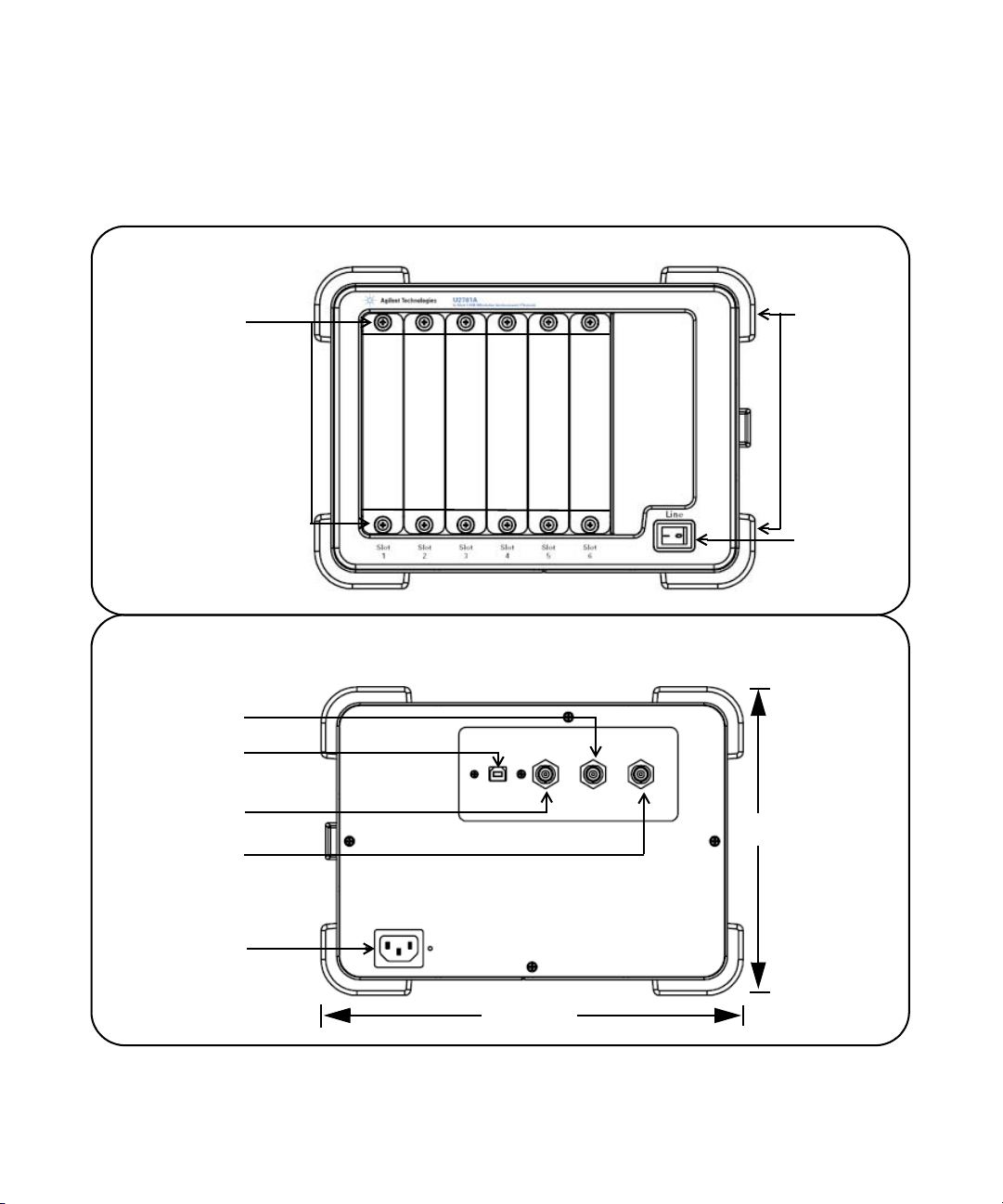
Product Outlook
Front View
Module
L-Mount Kit
Bumper
ON/OFF
switch
Rear View
Trigger In
USB Port
Trigger Out
197 mm
Ext 10 MHz
AC Input
270 mm
12 U2781A User’s Guide
Page 13

General Specifications
REMOTE INTERFACE
• USB 2.0 High Speed
• USBTMC Class Device
POWER CONSUMPTION
• 400 VA maximum
• Installation Category II
OPERATING ENVIRONMENT
• Operating temperature from 0 °C to +55 °C
• Relative humidity at 15% to 85% RH (non-condensing)
• Altitude up to 2000 meters
• Pollution Degree 2
• For indoor use only
STORAGE COMPLIANCE
• –20 °C to 70 °C
SAFETY COMPLIANCE
Certified with:
• IEC 61010-1:2001/EN 61010-1:2001 (2nd Edition)
• USA: UL61010-1: 2004
• Canada: CSA C22.2 No.61010-1:2004
EMC COMPLIANCE
• IEC/EN 61326-1 1998
• CISPR 11: 1990/EN55011:1991 , Group 1, Class A
• CANADA: ICES-001: 1998
• Australia/New Zealand: AS/NZS 2064.1
ACOUSTIC EMISSION
• Sound pressure level: 45.5 dB(A)
• Sound power level: 56.6 dB(A)
SHOCK & VIBRATION
• Tested to IEC/EN 60068-2
DIMENSION (WxDxH)
• 270.00 mm x 271.20 mm x 197.00 mm
WEIGHT
• 3.7 kg (without any modules slotted in)
• 6.0 kg (with maximum six modules slotted in)
WARRANTY
• One year
Getting Acquainted 1
U2781A User’s Guide 13
Page 14

1 Getting Acquainted
Electrical Specifications
Power Supply AC Input
Input voltage range 100 to 240 VAC
Input frequency range 50 to 60 Hz
Power consumption 400 VA maximum
Effiency 75%
Power Supply DC Output
Output rated voltage 12 VDC
Max output rated current 16.7 A
Max output rated power 200 W
Over voltage protection 13.2 to 16.2 V
Internal 10 MHz Reference Clock
Accuracy 25 ppm for operating range
Slot to slot skew 350 ps
External 10 MHz Reference Clock
Auto detection level Yes
Input frequency range 10 MHz
Input magnitude 100 mVpp to 5 Vpp (sine/square wave)
Input impedance 50 Ω ± 5 Ω
Damage level 10 Vrms
External Trigger In
Compatibility TTL
V
(Positive threshold voltage) 2.0 V
IH
V
(Negative threshold voltage) 0.8 V
IL
Hold time 8 ns pulse width
Input voltage range 0 to 5.0 V
Slot to slot skew 350 ps
External Trigger Out
V
OH
V
OL
Output voltage range 0 to 3.3 V
2.9 V
0.1 V
14 U2781A User’s Guide
Page 15

Mechanical Specifications
Physical Layout
Number of USB module slots 6
Dimension of each module slot 25.40 mm (W) x 174.54 mm (D) x 105.00 mm (H)
Dimension of chassis 270.00 mm (W) x 271.20 mm (D) x 197.00 mm (H)
Weight 3.7 kg
Power LED ON/OFF type
USB Backplane
Connector 55 pins Ernet male type C
Input signals External 10 MHz clock in (BNC connector)
Output signal Trigger out (BNC connector)
Cooling Fan
Number of fans 2
Fan speed 3300 rpm ±10%
Noise 37 dB(A)
Power (each fan) 2.52 W
Getting Acquainted 1
External trigger in (BNC connector)
U2781A User’s Guide 15
Page 16

1 Getting Acquainted
16 U2781A User’s Guide
Page 17

Agilent U2781A USB Modular Instrument Chassis
User’s Guide
2 Installation
L-Mount Kit Installation 18
Modular Chassis Installation 19
System Requirements 20
Hardware Requirements 20
Software Requirements 21
DAQ Driver Installation 21
Hardware Verification 25
Agilent Measurement Manager Software Installation 25
This chapter describes both the software and hardware installations of the
Agilent U2781A USB modular instrument chassis. It covers the L-Mount
kit installation, rackmount kit installation and the USB DAQ driver.
Agilent Technologies
17
Page 18

2 Installation
L-Mount Kit Installation
In order to slot in the USB module into the U2781A USB modular
instrument chassis, you need to fix the L - Mount kit on both sides of
the U2300A series DAQ.
NOTE
The L-Mount kit is provided when you purchase the U2300A series USB DAQ.
Below are simple instructions to install the L- Mount kit onto the
U2300A series DAQ. The instructions in page 21 shows how a USB
module is slot into the U2781A modular chassis.
Step 1
Use both the L-Mount kit that
are provided with the
USB module.
Step 2
By using a Philips head
screwdriver, tighten the screws
on both sides of the USB
module.
18 U2781A User’s Guide
Page 19

Modular Chassis Installation
Figures below show the installation of the USB module into the
U2781A modular instrument chassis. Follow the arrows shown below.
Installation 2
Step 1
Slot in the
USB module
into the
modular
chassis. Make
sure that the
55-pin
backplane
connector is
at the bottom.
Step 2
Secure both the thumb
screws onto the modular
chassis
U2781A User’s Guide 19
Page 20

2 Installation
System Requirements
Prior to installing the Agilent Measurement Manager software and the
USB DAQ driver, make sure your PC meets the following minimum
system requirements.
NOTE
The software installation for U2781A USB modular instrument chassis is similar to
U2300A series USB DAQ.
Hardware Requirements
Processor 500 MHz Pentium III or higher required
Operating system Windows 2000/XP
Browser Microsoft Internet Explorer 5.01 and above
Available RAM 256 MB above is recommended
Available disk space 225 MB required for installation
160 MB for Microsoft .NET Framework
65 MB for Agilent IO Libraries Suite
8118 KB for Agilent U2300A DAQ Driver
5125 KB for Agilent Measurement Manager
110 MB for Microsoft .NET Framework
65 MB for Agilent IO Libraries Suite
8118 KB for Agilent U2300A DAQ Driver
5125 KB for Agilent Measurement Manager
(1 GHz is recommended)
Software
175 MB required for operation
Software
Video Super VGA (800 x 600) 256 colors or more
20 U2781A User’s Guide
Page 21

Software Requirements
Software requirements Agilent IO Libraries Suite, T&M Toolkit and
Microsoft .NET Framework version 1.0 and 2.0
The Agilent IO Libraries Suite version 14.2 and above is
recommended. If possible, you should use the current version of the
Agilent IO Libraries Suite. Alternatively, you can install the Agilent IO
Libraries Suite with the required version directly from the Agilent
Automation- Ready CD.
Installation 2
NOTE
You are required to install the Agilent IO Libraries and DAQ Hardware Driver before
installing the Agilent Measurement Manager Software. You are recommended to
follow in sequence.
DAQ Driver Installation
NOTE
• You are required to install the DAQ driver at least once. If you have installed the
• The USB DAQ driver only compatible with Windows 2000 and Windows XP.
• Ensure that all devices are disconnected from PC before installing the driver.
Pre-installation of USB DAQ driver
DAQ driver when using the U2300A series USB DAQ, you do not need to install
it again.
• Verify that your PC meets the minimum hardware requirements
as stated in Hardware Requirements.
• Disconnect and unplug all devices from your PC.
• Ensure that Agilent IO Libraries Suite is installed before
proceeding.
U2781A User’s Guide 21
Page 22

2 Installation
Installing the USB DAQ driver
1 Unpack the U2781A USB modular instrument chassis.
2 Insert the Product Reference CD- ROM into the CD- ROM drive.
3 Installer will automatically execute the Agilent U2300 Series
Installation Menu. Click Hardware Driver to begin the installation of
USB DAQ driver.
Figure 2-1
4 If it does not auto execute, go to Start > Run (on the Windows Start
menu) and type <drive>:\Driver\Hardware\setup_hw.exe,
where <drive> is your CD- ROM drive. Click OK to begin installation.
22 U2781A User’s Guide
Page 23

Installation 2
5 The Agilent USB DAQ Driver dialog box will appear as shown in
figure 2- 2. Click Next to proceed.
Figure 2-2
6 Click Install to begin installation.
Figure 2-3
U2781A User’s Guide 23
Page 24

2 Installation
7 Click Finish when the installation is completed.
Figure 2-4
24 U2781A User’s Guide
Page 25

Hardware Verification
To verify that the hardware plugged in and installed is connected
properly, run the Agilent Connection Expert to do the hardware
verification
Agilent Connection Expert is one of the utility files in the Agilent IO
Libraries. The Connection Expert configures connected instruments
and enables communication. Connection Expert will automatically
detect the USB instruments when connected. To begin, Click Start > All
Programs > Agilent IO Libraries Suite > Agilent Connection Expert. The
connected devices will be visible in this application.
Agilent Measurement Manager Software Installation
Installation 2
NOTE
U2781A User’s Guide 25
• Verify that your PC meets the minimum requirements as stated in Hardware
Requirements.
• You do not need to install the Agilent Measurement Manager software again if
you have previously purchased and installed the U2300A series USB DAQ.
Page 26

2 Installation
26 U2781A User’s Guide
Page 27

Agilent U2781A USB Modular Instrument Chassis
User’s Guide
3 Features and Functions
Introduction 28
USB Backplane 29
Trigger Bus [0...7] 31
Trigger Out 32
External Trigger In (Star Trigger) 32
System Reference Clock 33
Chassis Temperature Monitoring 34
Fan Speed Monitoring 35
Identifying Modules Location 36
Georgraphical Address 36
Modules Identification 36
Simultaneous Synchronization (SSI) 38
This chapter describes the features and functions of the Agilent U2781A
modular instrument chassis. This includes the operation of the USB
backplane.
Agilent Technologies
27
Page 28

3 Features and Functions
Introduction
The Agilent U2781A USB modular instrument chassis provides
six USB modular slots and equipped with 200 W universal AC
power supply and built- in over current protection circuit. A
10MHz system reference clock is supplied to each modules slots.
There are two temperature sensors and a monitoring fan
control circuit to monitor the internal temperature and speed of
the fans. The fans are mainly used for heat dissipation.
The chassis also provides external 10MHz reference clock,
external trigger in and trigger out functions via BNC connectors
at the rear panel.
The key function for the chassis is to provide users with
flexibility when using the U2781A modular instrument chassis.
The modular chassis allocates housing for six USB modules
with built- in power supply. The USB backplane provides a
means to synchronize the modules.
The key features and functions of the Agilent U2781A USB
modular instrument chassis are explained in this chapter.
28 U2781A User’s Guide
Page 29

USB Backplane
Features and Functions 3
Figure 3- 1 illustrates the 55- pin assignment of the backplane
connector pin.
11 GND +12V +12V GND USB_D+ USB_D- GND
10 GND +12V +12V +12V GND GND GND
9 GND +12V +12V +12V GND USB_VBUS GND
8 GND LBL0 BRSV GND TRIG0 LBR0 GND
7 GND LBL1 GA0 TRIG7 GND LBR1 GND
6 GND LBL2 GA1 GND TRIG1 LBR2 GND
5 GND LBL3 GA2 TRIG6 GND LBR3 GND
4 GND LBL4 STAR TRIG GND TRIG2 LBR4 GND
3 GND LBL5 GND TRIG5 GND LBR5 GND
2 GND LBL6 CLK10M GND TRIG3 LBR6 GND
1 GND LBL7 GND TRIG4 GND LBR7 GND
ZA B C D E F
Figure3-1 55-pin backplane connector pin assignment
Tab l e 3 - 1 Pin information of SSI connector
SSI timing signal Functionality
+12V +12 V power from backplane
GND Ground
BRSV Reserved pin
TRIG0~TRIG7 Trigger bus 0 ~ 7
STAR_TRIG Star trigger
CLK10M 10MHz reference clock
USB_VBUS USB bus power, +5 V
USB_D+, USB_D- USB differential pair
LBL <0..7> and LBR <0..7> Reserved pin
GA0, GA1, GA2 Geographical address pin
U2781A User’s Guide 29
Page 30

3 Features and Functions
Figure3-2 USB backplane block diagram
30 U2781A User’s Guide
Page 31

Trigger Bus [0...7]
Features and Functions 3
Trigger Bus [0...7] is an 8- bit digital bus connected from slot 1
to slot 6 to synchronize different USB modules. This trigger bus
enables the USB modules of passing trigger signals to one
another.
To have one of the modules to control the operation of the other
modules, set the particular module as MASTER and the rest as
SLAVE (refer to “Simultaneous Synchronization (SSI)” on page
39 for more details). The control signal is sent from the Master
module to the SLAVE modules through this trigger bus. See
Figure 3- 3 for the bus architecture.
Figure3-3 Block diagram of Trigger Bus[0...7] and Trigger Out
In addition, the trigger bus can also be used to carry out the
pre- configuration of the chassis and modules before any
triggering activities. Refer to “Identifying Modules Location” on
page 38 for more information,
U2781A User’s Guide 31
Page 32

3 Features and Functions
Trigger Out
Trigger Out selects one of the trigger bus bit [0...7] for external
trigger. The USB device in Figure 3- 3 controls the multiplexer
switching for the trigger out selection.
The SCPI command below is used to set one of the trigger bus
[0…7] as external trigger source:
TRIGger:OUT {0|1|2|3|4|5|6|7}
Trigger Out Function
Bit-0 Time base
Bit-1 Reserved
Bit-2 Reserved
Bit-3 A/D trigger
Bit-4 Reserved
Bit-5 Reserved
Bit-6 Reserved
Bit-7 D/A trigger
External Trigger In (Star Trigger)
The star trigger bus offers a very high performance or precise
synchronization between modules.The star trigger bus is a
dedicated trigger line between the External Trigger Input and
USB slots. This trigger signal is sent from external to each slot
through a 1- to- 6 CLK buffer. The slot- to- slot skews are
minimized to ensure that trigger signal reaches all six slots
simultaneously. Refer Figure 3- 4 for the star trigger bus
architecture.
To set star trigger as the module trigger source, the SCPI
command below is sent to the modules:
OUTP:TRIG:SOUR STRG
32 U2781A User’s Guide
Page 33

Figure3-4 Block diagram of the 10 Mhz Reference Clock and External
Trigger In
System Reference Clock
The 10 MHz reference clock can come from two sources; internal
backplane oscillator and external clock source.
Features and Functions 3
The internal oscillator on the USB backplane supplies an
independent 10 MHz system reference clock to each of the USB
slot. This 10 MHz reference clock is driven through an
independent buffer. Refer to Figure 3- 4 for the block diagram.
Every clock trace is in equal distance to ensure that the slot to
slot skew is at minimum. Users can use this common reference
clock signal to synchronize multiple modules in a measurement
or control system.
The default SCPI command of ACQuire:RSIGnal AUTO will
scan thru and detect if there is any valid clock source from the
external BNC connector. If non is found, then the internal 10
MHz clock source will be used.
The SCPI command below will direct the reference clock source
to the internal 10 MHz:
ACQuire:RSIGnal INT
U2781A User’s Guide 33
Page 34

3 Features and Functions
Chassis Temperature Monitoring
The chassis contains a temperature control circuitry. It has two
thermistor sensors to sense the inner temperature of the
chassis. The temperature control circuitry communicates with
backplane USB device through an I
Figure 3- 5.
Figure3-5 Block diagram of temperature monitoring and fan control
2
C interface as illustrated in
The SCPI command below queries the temperature reading from
the sensors in
34 U2781A User’s Guide
o
C:
SYSTem:TEMPerature? {1|2}
Page 35

Fan Speed Monitoring
The U2781A USB modular instrument chassis is also integrated
with a fan speed control circuit. It is used to monitor the fan
status and speed. The control circuit communicates with
backplane USB device via I
To query the fan status, send the SCPI command below:
To query the fan speed in rpm, send the SCPI command below:
Features and Functions 3
2
C interface. Refer to Figure 3- 5.
SYSTem:FSTATus? {1|2}
SYSTem:FSPeed? {1|2}
U2781A User’s Guide 35
Page 36

3 Features and Functions
Identifying Modules Location
Georgraphical Address
Each slot in the chassis is designed with a 3- bit address pin,
which is designated as a location identity for USB modules. The
address for all six slots are as below:
Slot Address
1001
2010
3011
4100
5101
6110
The USB modules are able to read this 3- bit data and know
which slot the module is plugged in. To read the geographical
address of each module, the SCPI command below is used:
SYSTem:CDEScription?
Modules Identification
You may have more than one module or chassis connected to
the same host PC. Figure 3- 6 illustrates an example of the
connection.
36 U2781A User’s Guide
Page 37

Features and Functions 3
Figure3-6 Identifying modules location
In order to identify the location of the modules, a
pre- configuration setting is needed before the synchronization
or triggering event begins. Follow the steps below:
1 Send the following command to the modular chassis to
trigger it. This command will be used to transmit the number
to all USB modules via Trigger Bus [0...7]. You can choose
from 1 to 255 for your chassis number.
SYSTem:IDentity {1|2|3…|255}
2 Send the following command to every module in the chassis
to query each of the slot and chassis numbers.
SYST:CDES?
3 You may need to perform some sorting routine to determine
which slot it is at and what is the assigned number of its host
chassis. If a chassis has six modules in it, then there will be a
total of 7 SCPI commands to send to chassis and modules.
U2781A User’s Guide 37
Page 38

3 Features and Functions
4 During this identification operation, the trigger bus is used.
Hence, any triggering activities on the backplane would be
blocked.
5 Prior to any triggering activities, you must stop the
configuration activity by sending the following command:
SYSTem:IDentity {0|OFF}
NOTE
• Do not execute the above mentioned steps when the USB modules are in the
process of acquiring data.
• You do not need to perform the above pre-configuration if you are using the
Agilent Measurement Manager software. You are only required to press the
“Refresh” button.
Simultaneous Synchronization (SSI)
Simultaneous Synchronization (SSI) provides synchronization
between the USB modules. Figure 3- 7 illustrates an example of
SSI.
SSI allows you to set one of the modules as MASTER and others
as SLAVE. MASTER module sends the SSI signal to the slave
modules via the backplane trigger bus. SLAVE modules will
then receive the signal and begin synchronization with MASTER
module.
The SCPI command below is used to set the module as master:
Send the SCPI command below to set the module as SLAVE:
CONF:SSI MAST
CONF:SSI SLAV
NOTE
38 U2781A User’s Guide
Only ONE master is assigned.
Page 39

Features and Functions 3
Figure3-7 Synchronization between modules in the chassis
U2781A User’s Guide 39
Page 40

3 Features and Functions
40 U2781A User’s Guide
Page 41

Agilent U2781A USB Modular Instrument Chassis
User’s Guide
4 General Maintenance
This chapter gives a brief desciption on how to maintain the U2781A USB
modular instrument chassis.
Agilent Technologies
41
Page 42

4 General Maintenance
NOTE
Repair or service which are not covered in this manual should only be
performed by qualified personnel.
To remove the dirt or moisture in the chassis panel, the cleaning steps
are as follows:
1 Turn off the unit and remove the power cord and I/O cable.
2 Shake out any dirt that may have accumulated inside the chassis
unit.
3 Wipe the chassis with a dry cloth.
42 U2781A User’s Guide
Page 43

www.agilent.com
Contact us
o obtain service, warranty or technical
T
support assistance, contact us at the following
phone numbers:
United States:
(tel) 800 829 4444 (fax) 800 829 4433
Canada:
(tel) 877 894 4414 (fax) 800 746 4866
China:
(tel) 800 810 0189 (fax) 800 820 2816
Europe:
(tel) 31 20 547 2111
Japan:
(tel) (81) 426 56 7832 (fax) (81) 426 56
7840
Korea:
(tel) (080) 769 0800 (fax) (080) 769 0900
Latin America:
(tel) (305) 269 7500
Ta i w a n :
(tel) 0800 047 866 (fax) 0800 286 331
Other Asia Pacific Countries:
(tel) (65) 6375 8100 (fax) (65) 6755 0042
Or visit Agilent worlwide web at:
www.agilent.com/find/assist
Product specifications and descriptions in
this document subject to change without notice.
© Agilent Technologies, Inc. 2006
Printed in Malaysia
November 29, 2006
U2781-90003
Agilent Technologies
 Loading...