

Page 1

Agilent U2781A
USB Modular
Instrument Chassis
User’s Guide
Agilent Technologies
Page 2

Notices
CAUTION
WARNING
© Agilent Technologies, Inc. 2006 - 2011
No p art o f this manu al may be re produce d in
any form or by any means (including electronic storage and retrieval or translation
into a foreign language) without prior agreement and written consent from Agilent
Technologies, Inc. as governed by United
States and international copyright laws.
Manual Part Number
U2781-90003
Edition
Fifth Edition, November 8, 2011
Printed in Malaysia
Agilent Technologies, Inc.
Bayan Lepas Free Industrial Zone,
11900 Penang, Malaysia
Trademark Acknowledgements
Pentium is a U.S. registered trademark of
Intel Corporation.
Microsoft, Visual Studio, Windows, and MS
Windows are trademarks of Microsoft Corporation in the United States and/or other
countries.
Warranty
The material contained in this document is provided “as is,” and is subject to being changed, without notice,
in future editions. Further, to the maximum extent permitted by applicable
law, Agilent disclaims all warranties,
either express or implied, with regard
to this manual and any information
contained herein, including but not
limited to the implied warranties of
merchantability and fitness for a particular purpose. Agilent shall not be
liable for errors or for incidental or
consequential damages in connection with the furnishing, use, or performance of this document or of any
information contained herein. Should
Agilent and the user have a separate
written agreement with warranty
terms covering the material in this
document that conflict with these
terms, the warranty terms in the separate agreement shall control.
Technology Licenses
The hardware and/or software described in
this document are furnished under a license
and may be used or copied only in accordance with the terms of such license.
Restricted Rights Legend
U.S. Government Restricted Rights. Software and technical data rights granted to
the federal government include only those
rights customarily provided to end user customers. Agilent provides this customary
commercial license in Software and technical data pursuant to FAR 12.211 (Technical
Data) and 12.212 (Computer Software) and,
for the Department of Defense, DFARS
252.227-7015 (Technical Data - Commercial
Items) and DFARS 227.7202-3 (Rights in
Commercial Computer Software or Computer Software Documentation).
Safety Notices
A CAUTION notice denotes a
hazard. It calls attention to an operating procedure, practice, or the
like that, if not correctly performed
or adhered to, could result in damage to the product or loss of important data. Do not proceed beyond a
CAUTION notice until the indicated
conditions are fully understood and
met. If the equipment is used in a
manner not specified by the
manufaturer, the protection
provided by the equipment may be
impaired.
A WARNING notice denotes a
hazard. It calls attention to an
operating procedure, practice, or
the like that, if not correctly performed or adhered to, could result
in personal injury or death. Do not
proceed beyond a WARNING
notice until the indicated conditions are fully understood and
met.
II U2781A User’s Guide
Page 3
Safety Information
The following general safety precautions must be observed during all phases of
this instrument. Failure to comply with these precautions or with specific
warnings elsewhere in this manual violates safety standards of design,
manufacture, and intended use of the instrument. Agilent Technologies, Inc.
assumes no liability for the customer’s failure to comply with these requirements.
Safety Symbols
The following symbols indicate that precautions must be taken to maintain safe
operation of the instrument.
Direct current
Warning
Regulatory Markings
The CE mark shows that the product complies with all the
relevant European Legal Directives (if accompanied by a year, it
signifies when the design was proven).
The CSA mark is a registered trademark of the Canadian
Standards Association. A CSA mark with the indicators "C" and
"US" means that the product is certified for both the U.S. and
Canadian markets, to the applicable American and Canadian
standards.
The C-tick mark is a registered trademark of the Spectrum
Management Agency of Australia. This signifies compliance with
the Australian EMC Framework regulations under the terms of
the Radio Communications Act of 1992.
ICES/NMB-001
This ISM device complies with the Canadian ICES-001.
U2781A User’s Guide III
Page 4

General Safety Information
WARNING
CAUTION
• Do not use the device if it is damaged. Before you use the device,
inspect the case. Look for cracks or missing plastic. Do not operate
the device around explosive gas, vapor or dust.
• Do not apply more than the rated voltage (as marked on the device)
between terminals, or between terminal and external ground.
• Always use the device with the cables provided.
• Observe all markings on the device before connecting to the device.
• Turn off the device and application system power before connecting
to the I/O terminals.
• When servicing the device, use only specified replacement parts.
• Do not operate the device with the removable cover removed or
loosened.
• Do not connect any cables and terminal block prior to performing
self-test process.
• Do not load the output terminals above the specified current limits.
Applying excessive voltage or overloading the device will cause
irreversible damage to the circuitry.
• Applying excessive voltage or overloading the input terminal will
damage the device permanently.
• If the device is used in a manner not specified by the manufacturer, the
protection provided by the device may be impaired.
• Always use dry cloth to clean the device. Do not use ethyl alcohol or
any other volatile liquid to clean the device.
• Do not permit any blockage of the ventilation holes of the device.
IV U2781A User’s Guide
Page 5
Waste Electrical and Electronic Equipment (WEEE) Directive
2002/96/EC
This instrument complies with the WEEE Directive (2002/96/EC) marking
requirement. This affixed product label indicates that you must not discard this
electrical/electronic product in domestic household waste.
Product Category:
With reference to the equipment types in the WEEE directive Annex 1, this
instrument is classified as a “Monitoring and Control Instrument” product.
The affixed product label is shown as below:
Do not dispose in domestic household waste
To return this unwanted instrument, contact your nearest Agilent office, or visit:
http://www.agilent.com/environment/product
for more information.
U2781A User’s Guide V
Page 6

In This Guide…
1Getting Started provides an overview of the U2781A USB modular instrument
chassis, the product outlook and dimension. This chapter also contains
instructions on how to get started with the U2781A USB modular chassis.
2 Features and Functions provides information for better understanding of the
features and functions of the U2781A USB modular instrument chassis.
3 Characteristics and Specifications specifies the characteristics, environment
conditions, and specifications of the U2781A USB modular instrument chassis.
VI U2781A User’s Guide
Page 7
DECLARATION OF CONFORMITY
According to ISO/IEC Guide 22 and CEN/CENELEC EN 45014
Generic example
Manufacturer’s Name:
Agilent Technologies Microwave Products (M) Sdn. Bhd
Manufacturer’s Address:
Bayan Lepas Free Industrial Zone,
11900, Bayan Lepas, Penang, Malaysia
Declares under sole responsibility that the product as originally delivered
Product Name:
USB Modular Instrument Chassis (USB Card cage)
Models Number:
U2781A
Product Options:
This declaration covers all options of the above product(s)
complies with the essential requirements of the following applicable European Directives, and
carries the CE marking accordingly:
Low Voltage Directive (73/23/EEC, amended by 93/68/EEC)
EMC Directive (89/336/EEC, amended by 93/68/EEC)
and conforms with the following product standards:
EMC
Standard
StandardStandard
Standard Limit
LimitLimit
Limit
IEC 61326-1:1997+A1:1998 / EN 61326-1:1997+A1:1998
CISPR 11:1990 / EN55011:1991 Class A Group 1
IEC 61000-4-2:1995+A1:1998 / EN 61000-4-2:1995 4 kV CD, 8 kV AD
IEC 61000-4-3:1995 / EN 61000-4-3:1995 3 V/m, 80-1000 MHz
IEC 61000-4-4:1995 / EN 61000-4-4:1995 0.5 kV signal lines, 1 kV power lines
IEC 61000-4-5:1995 / EN 61000-4-5:1995 0.5 kV line-line, 1 kV line-ground
IEC 61000-4-6:1996 / EN 61000-4-6:1996 3 V, 0.15-80 MHz
IEC 61000-4-11:1994 / EN 61000-4-11:1994 1 cycle / 100%
Canada: ICES-001:1998
Australia/New Zealand: AS/NZS 2064.1
The product was tested in a typical configuration with Agilent Technologies test systems.
Safety
IEC 61010-1:2001 / EN 61010-1:2001
Canada: CSA C22.2 No. 61010-1:2004
USA: UL 61010-1: 2004
Supplementary Information:
U2781A is USB Modular Instrument chassis with 6 USB modules slot.
This DoC applies to above-listed products placed on the EU market after:
19-Dec-2006
Date
Mack Soh
Quality Manager
For further information, please contact your local Agilent Technologies sales office, agent or distributor,
or Agilent Technologies Deutschland GmbH, Herrenberger Straße 130, D 71034 Böblingen, Germany.
Template: A5971-5302-2, Rev. B.01 U2781A Rev 1.0
U2781A User’s Guide VII
Page 8

Product Regulations
Performance Criteria
IEC 61326-1:1997+A1:1998 / EN 61326-1:1997+A1:1998
CISPR 11:1990 / EN 55011:1991
– Group 1 Class A
IEC 61000-4-2:1995+A1:1998 / EN 61000-4-2:1995
(ESD 4kV CD, 8kV AD)
B
IEC 61000-4-3:1995 / EN 61000-4-3:1995
(3V/m, 80% AM)
A
IEC 61000-4-4:1995 / EN 61000-4-4:1995
(EFT 0.5kV line-line, 1kV line-earth)
B
IEC 61000-4-5:1995 / EN 61000-4-5:1995
(Surge 0.5kV line-line, 1kV line-earth)
B
IEC 61000-4-6:1996 / EN 61000-4-6:1996
(3V, 0.15~80 MHz, 80% AM, power line)
A
IEC 61000-4-11:1994 / EN 61000-4-11:1994
(Dips 1 cycle, 100%)
C
Canada: ICES-001:1998
Australia/New Zealand: AS/NZS 2064.1
EMC
IEC 61010-1:2001 / EN 61010-1:2001
Canada: CSA C22.2 No. 61010-1:2004
Safety
USA: UL 61010-1: 2004
Additional Information:
The product herewith complies with the essential requirements of the Low Voltage Directive 73/23/EEC and the
EMC Directive 89/336/EEC (including 93/68/EEC) and carries the CE Marking accordingly (European Union).
1
Performance Criteria:
A Pass - Normal operation, no effect.
B Pass - Temporary degradation, self recoverable.
C Pass - Temporary degradation, operator intervention required.
D Fail - Not recoverable, component damage.
N/A – Not applicable
Notes:
Regulatory Information for Canada
ICES/NMB-001:1998
This ISM device complies with Canadian ICES-001.
Cet appareil ISM est confomre à la norme NMB-001 du Canada.
Regulatory Information for Australia/New Zealand
This ISM device complies with Australian/New Zealand AS/NZS 2064.1
VIII U2781A User’s Guide
Page 9

Contents
Contents
1 Getting Started
Introduction 2
Product Overview 3
Product Outlook 3
Dimensions 4
Standard Purchase Items Checklist 5
Installations and Configurations 6
General Maintenance 7
2 Features and Functions
Introduction 10
USB Backplane 11
Trig ge r Bu s (T R IG [0. .7] ) 13
External Trigger Out 14
External Trigger In (Star Trigger) 15
Simultaneous Synchronization (SSI) 16
Single Master–multiple Slaves 18
Multiple Master–multiple Slaves 21
System Reference Clock 23
Chassis Temperature Monitoring 24
Fan Speed Monitoring 25
Identifying Modules Location 26
Geographical Address 26
Modules Identification 26
3 Characteristics and Specifications
Product Characteristics 30
Electrical Specifications 32
Mechanical Specifications 33
U2781A User’s Guide IX
Page 10

Contents
List of Figures
Figure 2-1 USB backplane block diagram 12
Figure 2-2 Block diagram of Trigger Bus (TRIG [0..7]) and Trigger Out 13
Figure 2-3 Block diagram of the 10 Mhz Reference Clock and External Trigger
In 15
Figure 2-4 Synchronization between modules in the chassis 17
Figure 2-5 Single Master–multiple Slave triggering with DAQ 18
Figure 2-6 Single Master–multiple Slave triggering 19
X U2781A User’s Guide
Page 11

Figure 2-7 Multiple Master–multiple Slave triggering 21
Figure 2-8 Block diagram of temperature monitoring and fan control 24
Figure 2-9 Identifying modules location 27
Contents
U2781A User’s Guide XI
Page 12

Contents
List of Tables
Ta b l e 2 - 1 Pin information of SSI connector 11
Ta b l e 2 - 2 Trigger out bits for U2300A, U2500A, and U2600A Series DAQ
devices 14
Ta b l e 2 - 3 Example of configurations for single Master-multiple Slaves using
DAQ and U2700A Series modular products. 20
Ta b l e 2 - 4 Example of configurations for multiple Master–multiple Slaves 22
XII U2781A User’s Guide
Page 13

Agilent U2781A USB Modular Instrument Chassis
User’s Guide
1 Getting Started
Introduction 2
Product Overview 3
Product Outlook 3
Dimensions 4
Standard Purchase Items Checklist 5
Installations and Configurations 6
General Maintenance 7
This chapter provides an overview of the U2781A USB modular instrument
chassis, the product outlook and dimension. This chapter also contains
instructions on how to get started with the chassis from the installation of
modules to the chassis to the installations of hardware and software to
the start-up and configurations of Agilent Measurement Manager
application software.
Agilent Technologies
1
Page 14

1Getting Started
Introduction
The U2781A USB modular instrument chassis is a 4U height
chassis with six USB module slots. It is a portable chassis with
high performance added value. It targets a wide range of
applications in both industrial and scientific environments. It helps
to lower cost of test and accelerate your test system integration
and development.
The Agilent U2781A is equipped with USB plug- and- play
connectivity. The USB interface that is compliant with the
TMC- 488.2 Standards work seamlessly with Agilent Measurement
Manager software and can be controlled remotely via industry
standard SCPI commands. In addition, the U2781A modular
instrument chassis comes with Agilent IO Libraries Suite 14.2.
The U2781A modular instrument chassis comes with star trigger
bus, which offers precise synchronization between USB modules
and the external trigger signal. The star trigger bus is a dedicated
trigger lines between the external trigger input and USB slots.
The Agilent U2781A USB modular instrument chassis can be
applied to nearly any industrial data acquisition, industrial
automation and education environment. The primary advantage is
its synchronization capability between modules.
2 U2781A User’s Guide
Page 15
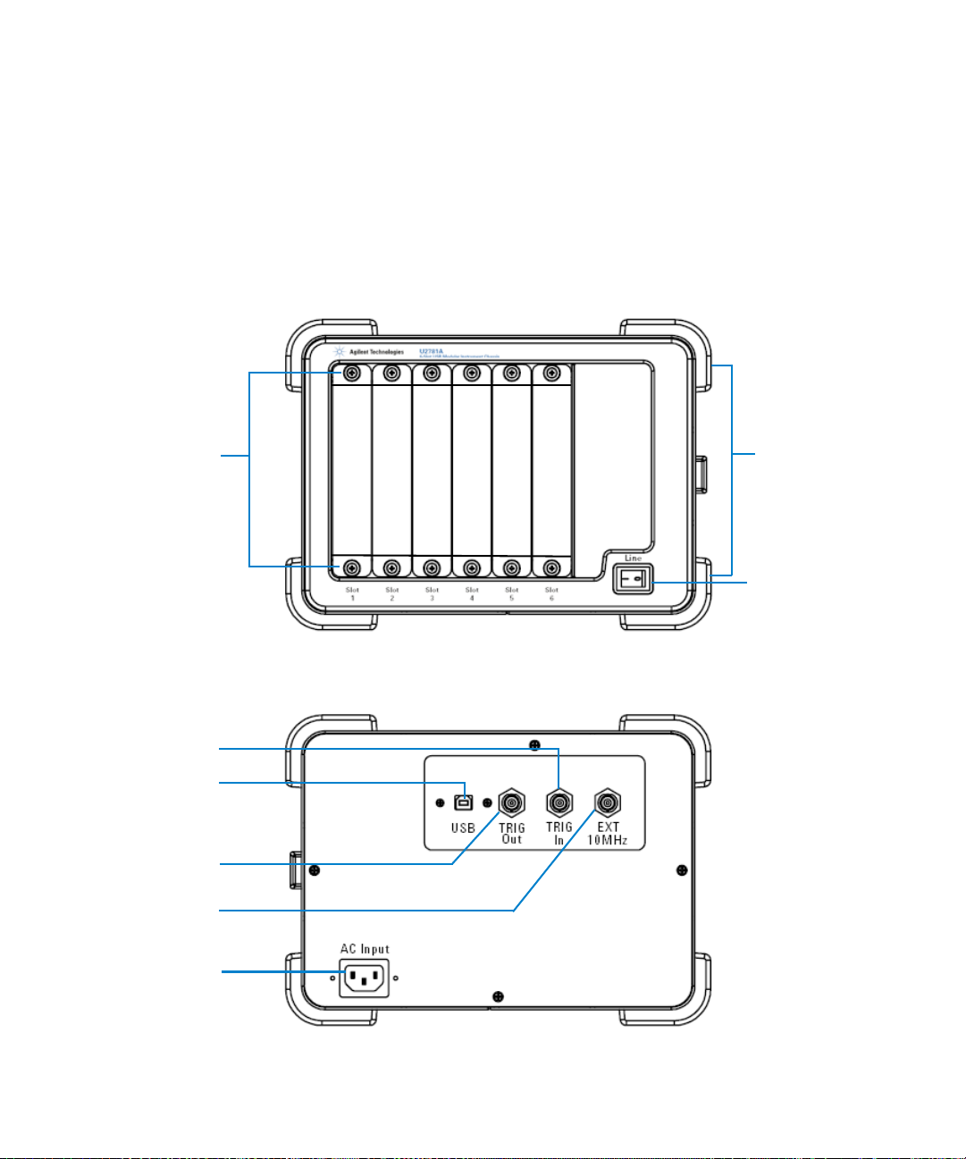
Product Overview
Module
L-Mount Kit
ON/OFF
switch
Bumper
Trigger In
USB Port
Trigger Out
Ext 10 MHz
AC Input
Product Outlook
Getting Started 1
Front View
U2781A User’s Guide 3
Rear View
Page 16

1Getting Started
270.00 mm
271.20 mm
197.00 mm
Dimensions
4 U2781A User’s Guide
Page 17

Standard Purchase Items Checklist
Inspect and verify the following items for the standard purchase of
U2781A USB modular instrument chassis. If there are missing
items, contact the nearest Agilent Sales Office.
✔ Power cord
✔ USB Extension Cable
✔ Agilent USB Modular Products and Systems Quick Start Guide
✔ Agilent USB Modular Products and Systems Product Reference
DVD- ROM
✔ Agilent Automation- Ready CD- ROM (contains the Agilent IO
Libraries Suite)
✔ Functional Test Certificate
Getting Started 1
U2781A User’s Guide 5
Page 18

1Getting Started
NOTE
Installations and Configurations
If you are using the U2781A USB modular instrument chassis with
the Agilent Measurement Manager, follow the step- by- step
instructions as shown in the Agilent USB Modular Products and
Systems Quick Start Guide.
You need to install IVI-COM driver before using the U2781A Series with
Agilent VEE, LabVIEW or Microsoft Visual Studio.
6 U2781A User’s Guide
Page 19

General Maintenance
NOTE
Repair or service which are not covered in this manual should only be performed by
qualified personnel.
To remove the dirt or moisture in the chassis panel, the cleaning
steps are as follows:
1 Power off the chassis device and remove the power cord and I/O
cable from the chassis.
2 Shake out any dirt that may have accumulated inside the
chassis device.
3 Wipe the chassis with a dry cloth.
Getting Started 1
U2781A User’s Guide 7
Page 20

1Getting Started
8 U2781A User’s Guide
Page 21

Agilent U2781A USB Modular Instrument Chassis
User’s Guide
2 Features and Functions
Introduction 10
USB Backplane 11
Trigger Bus (TRIG [0..7]) 13
External Trigger Out 14
External Trigger In (Star Trigger) 15
Simultaneous Synchronization (SSI) 16
Single Master–multiple Slaves 18
Multiple Master–multiple Slaves 21
Simultaneous Synchronization (SSI) 16
Chassis Temperature Monitoring 24
Fan Speed Monitoring 25
Identifying Modules Location 26
Geographical Address 26
Modules Identification 26
This chapter provides information for better understanding of the features
and functions of the U2781A USB modular instrument chassis.
Agilent Technologies
9
Page 22

2 Features and Functions
Introduction
The Agilent U2781A USB modular instrument chassis
provides six USB modular slots and is equipped with 200 W
universal AC power supply and built- in over current
protection circuit. A 10 MHz system reference clock is
supplied to each modules slots. There are two temperature
sensors and a monitoring fan control circuit to monitor the
internal temperature and speed of the fan. The fan is mainly
used for heat dissipation.
The chassis also provides external 10 MHz reference clock,
external trigger in and trigger out functions via BNC
connectors at the rear panel.
The key function for the chassis is to provide users with
flexibility when using the U2781A modular instrument
chassis. The modular chassis allocates housing for six USB
modules with built- in power supply. The USB backplane
provides a means to synchronize the modules.
The key features of the U2781A USB modular instrument
chassis are as follows:
• Simultaneous Synchronization (SSI)
• Star trigger
• Internal and external 10 MHz reference clock
• Trigger in and trigger out signals
• Standard SCPI commands
• IVI- COM driver compatibility
• USBTMC 488.2 compliant
• Hi- Speed USB 2.0 interface
The key functions of the Agilent U2781A USB modular
instrument chassis will be elaborated in the following
sections.
10 U2781A User’s Guide
Page 23

USB Backplane
Features and Functions 2
55-Pin Backplane Connector Pins Configuration
11 GND +12V +12V GND USB_D+ USB_D- GND
10 GND +12V +12V +12V GND GND GND
9 GND +12V +12V +12V GND USB_VBUS GND
8 GND LBL0 BRSV GND TRIG0 LBR0 GND
7 GND LBL1 GA0 TRIG7 GND LBR1 GND
6 GND LBL2 GA1 GND TRIG1 LBR2 GND
5 GND LBL3 GA2 TRIG6 GND LBR3 GND
4 GND LBL4 STAR TRIG GND TRIG2 LBR4 GND
3 GND LBL5 GND TRIG5 GND LBR5 GND
2 GND LBL6 CLK10M GND TRIG3 LBR6 GND
1 GND LBL7 GND TRIG4 GND LBR7 GND
ZA B C D E F
Tab l e 2 - 1 Pin information of SSI connector
SSI timing signal Functionality
+12V +12 V power from backplane
GND Ground
BRSV Reserved pin
TRIG0~TRIG7 Trigger bus 0 ~ 7
STAR_TRIG Star trigger
CLK10M 10MHz reference clock
USB_VBUS USB bus power, +5 V
USB_D+, USB_D– USB differential pair
LBL <0..7> and LBR <0..7> Reserved pin
GA0, GA1, GA2 Geographical address pin
U2781A User’s Guide 11
Page 24

2 Features and Functions
Figure 2-1 USB backplane block diagram
12 U2781A User’s Guide
Page 25

Trigger Bus (TRIG [0..7])
TRIG [0..7]
Trigger Bus (TRIG [0..7]) is an 8- bit digital bus connected
from slot 1 to slot 6 to synchronize different USB modules.
This trigger bus enables the USB modules of passing trigger
signals to one another.
To have one of the modules to control the operation of the
other modules, set the particular module as MASTER and
the rest as SLAVE (refer to Simultaneous Synchronization (SSI)
for more details). The control signal is sent from the
MASTER module to the SLAVE modules through this trigger
bus. See following figure for the bus architecture.
Features and Functions 2
Figure 2-2 Block diagram of Trigger Bus (TRIG [0..7]) and Trigger Out
In addition, the trigger bus can also be used to carry out the
pre- configuration of the chassis and modules before any
triggering activities. Refer to Identifying Modules Location for
more information.
U2781A User’s Guide 13
Page 26

2 Features and Functions
External Trigger Out
Trigger Out selects one of the eight lines from trigger bus
(TRIG [0..7]) as an external trigger source. The selection of
the trigger out line is done by the USB device in the chassis
as illustrated in Figure 2- 2 by means of a multiplexer.
Table 2- 2 defines the available trigger out signals provided
by U2300A, U2500A, and U2600A Series DAQ, whereas for
U2700A Series modular products, user is allowed to choose
any trigger line from the trigger bus (TRIG [0..7]) as an
external trigger source.
The SCPI command below is used to select one of the lines
or bits of the trigger bus (TRIG [0..7]) as an external trigger
source:
TRIGger:OUT {0|1|2|3|4|5|6|7}
Tab l e 2 - 2 Trigger out bits for U2300A, U2500A, and U2600A Series DAQ
devices
Trigger Out Function
Bit-0 Time base
Bit-1 Reserved
Bit-2 Reserved
Bit-3 A/D trigger
Bit-4 Reserved
Bit-5 Reserved
Bit-6 Reserved
Bit-7 D/A trigger
14 U2781A User’s Guide
Page 27

External Trigger In (Star Trigger)
Star Trigger Bus
The star trigger bus offers a very high performance or
precise synchronization between modules. The star trigger
bus is a dedicated trigger line between the External Trigger
Input and USB slots. This trigger signal is sent from external
to each slot through a 1- to- 6 CLK buffer. The slot-to- slot
skews are minimized to ensure that trigger signal reaches all
six slots simultaneously. Refer to the following figure for the
star trigger bus architecture illustration.
To set star trigger as the module trigger source, the following
SCPI command is sent to the modules:
OUTP:TRIG:SOUR STRG
Features and Functions 2
Figure 2-3 Block diagram of the 10 Mhz Reference Clock and External
Trigger In
U2781A User’s Guide 15
Page 28

2 Features and Functions
NOTE
Simultaneous Synchronization (SSI)
Simultaneous Synchronization (SSI) provides synchronization
between the modular products within the chassis. Figure 2- 4
illustrates an example of SSI. The SSI feature should be
configured using the bundled Agilent Measurement Manager
(AMM).
SSI allows users to set the modules as MASTER or SLAVE.
The MASTER module sends the SSI signal to the slave
modules via the backplane trigger bus (TRIG [0..7]). SLAVE
modules will then receive the signal and begin
synchronization with MASTER module.
There are two SSI configuration modes available — single
Master–multiple Slaves and multiple Masters–multiple Slaves.
• Only ONE master can be assigned for U2300A, U2500A, and U2600A Series.
• For more information, refer to the AMM Help File, Chassis Trigger page.
16 U2781A User’s Guide
Page 29

Features and Functions 2
MASTER Module
FPGA
55-pin
Connectors
USB
Interface
To PC wi t h A MM
SLAVE module 1
SLAVE module 2
FPGA
SSI Signals
SSI Signals
SSI Trigger Bus
Chassis
55-pin
Connectors
55-pin
Connectors
55-pin
Connectors
55-pin
Connectors
55-pin
Connectors
55-pin
Connectors
55-pin
Connectors
55-pin
Connectors
SLAVE module 1
SLAVE module 2
FPGA
SSI Signals
55-pin
Connectors
MASTER Module
FPGA
SSI Signals
Figure 2-4 Synchronization between modules in the chassis
U2781A User’s Guide 17
Page 30

2 Features and Functions
NOTE
Single Master–multiple Slaves
In this configuration, only one Master module is allowed to
send the SSI trigger event to the receiving Slave modules.
Configuration with Agilent U2300A, U2500A, and U2600A Series
DAQ only
When there is one or more U2300A, U2500A, or U2600A
Series DAQ in the SSI configuration, SSI allows users to set
only one of the modules as MASTER and others as SLAVE
through AMM. Alternatively, users can also set this
configuration using the SCPI commands.
Refer to U2300A, U2500A, and U2600A Series DAQ Programmer's
Reference.
Figure 2-5 Single Master–multiple Slave triggering with DAQ
18 U2781A User’s Guide
Page 31

Features and Functions 2
Configuration with combination of Agilent U2300A, U2500A,
U2600A Series DAQ and U2700A Series modular products
With one DAQ configured as Master, all of the other U2700A
Series modular devices can only be configured as Slave to
receive the event of the signal as shown in Table 2- 2.
Figure 2-6 Single Master–multiple Slave triggering
Table 2- 3 shows some examples of supported and not
supported configurations.
U2781A User’s Guide 19
Page 32

2 Features and Functions
Tab l e 2 - 3 Example of configurations for single Master-multiple Slaves using DAQ and U2700A Series modular
products.
Slot 1 Slot 2 Slot 3 Slot 4 & Slot 5 Slot 6
DAQ U2701A/U2702A U2761A U2722A DAQ
Supported configurations
Configuration 1 M = T0 – T7 S = T0 S = T3 S = T7 S = T0 – T7
Configuration 2 None M = T1 S = T1 S = T1 None
Configuration 3 M = T0 – T7 None None None S = T0 – T7
Not supported configurations
Configuration 1
Configuration 2
Configuration 3
Configuration 4
[1]
[2]
[2]
[2]
M = T0 – T7 M = T1 S = T1 S = T2 None
S = T0 – T7 M = T1 S = T1 S = T2 None
S = T0 – T7 M = T1 S = T1 S = T1 None
S = T0 – T7 M = T0 – T7 S = T0 S = T0 None
M — Master, S — Slave, T0~T7 — Trigger bus (TRIG [0..7]), * — Star Trigger
[1]
Multiple Master is not allowed with DAQ set as Master.
[2]
U2700A Series modular devices should not be configured as Master.
20 U2781A User’s Guide
Page 33

Multiple Master–multiple Slaves
In this configuration, groups of single Master- multiple Slaves
are allowed in order to perform multiple synchronizations
simultaneously. This configuration is only supported by
U2700A Series modular products.
Features and Functions 2
Figure 2-7 Multiple Master–multiple Slave triggering
Table 2- 4 shows some examples of supported and not
supported configurations. Example of configurations for
multiple Master–multiple Slaves.
U2781A User’s Guide 21
Page 34

2 Features and Functions
Tab l e 2 - 4 Example of configurations for multiple Master–multiple Slaves
Slot 1 Slot 2 Slot 3 Slot 4 Slot 5 & Slot 6
U2701A U2702A U2761A U2751A U2722A
Supported configurations
Configuration 1 M = T0 S = T0 S = T0 None S = T0
Configuration 2 S = T1 M = T1 None None S = T1
Configuration 3 M = T0 M = T1 S = T0 None S = T1
Configuration 4 *(Out)
M = T1
Configuration 5 *(Out) * (In) * (In) None * (In)
Not supported configurations
Configuration 1
Configuration 2
Configuration 3
[1]
[2]
[3]
M = T0 M = T0 S = T0 None S = T0
M = T3 S = T3
M = T0
S = T1
Configuration 4
[4]
*(Out)
M = T1
S = T1 * (In) None S = T1
M = T4 None S = T4
S = T4
S = T0 S = T0 None S = T1
* (In)
None None None
S = T1
M — Master, S — Slave, T0~T7 — Trigger bus (TRIG [0..7]), * — Star Trigger
[1]
Same trigger line is not allowed for multiple Master configuration.
[2]
Slave device not allowed to occupy two trigger lines.
[3]
Not allowed to have both Master and Slave configuration for a device.
[4]
Not allowed to have Star Trigger and Slave mode for a device.
22 U2781A User’s Guide
Page 35

System Reference Clock
The 10 MHz reference clock can come from two sources;
internal backplane oscillator and external clock source.
The internal oscillator on the USB backplane supplies an
independent 10 MHz system reference clock to each of the
USB slot. This 10 MHz reference clock is driven through an
independent buffer. Refer to Figure 2- 3 for the block
diagram. Every clock trace is in equal distance to ensure
that the distance of the slot to the slot skew is minimized.
Users can use this common reference clock signal to
synchronize multiple modules in a measurement or control
system.
The default SCPI command of ACQuire:RSIGnal AUTO will
scan through and detect if there is any valid clock source
from the external BNC connector. If none is found, then the
internal 10 MHz clock source will be used.
The SCPI command below will direct the reference clock
source to the internal 10 MHz:
Features and Functions 2
ACQuire:RSIGnal INT
U2781A User’s Guide 23
Page 36

2 Features and Functions
Chassis Temperature Monitoring
The chassis contains a temperature control circuitry. It has
two thermistor sensors to sense the inner temperature of the
chassis. The temperature control circuitry communicates
with backplane USB device through an I
illustrated in following figure.
2
C interface as
Figure 2-8 Block diagram of temperature monitoring and fan control
The SCPI command below queries the temperature reading
from the sensors in degree Celsius (°C):
SYSTem:TEMPerature? {1|2}
24 U2781A User’s Guide
Page 37

Fan Speed Monitoring
Features and Functions 2
The U2781A USB modular instrument chassis is also
integrated with a fan speed control circuit. It is used to
monitor the fan status and speed. The control circuit
communicates with backplane USB device via I
Refer to Figure 2-8.
To query the fan status, send the SCPI command below:
SYSTem:FSTATus? {1|2}
To query the fan speed in revolutions per minute (rpm),
send the SCPI command below:
SYSTem:FSPeed? {1|2}
2
C interface.
U2781A User’s Guide 25
Page 38

2 Features and Functions
Identifying Modules Location
Geographical Address
Each slot in the chassis is designed with a 3- bit address pin,
which is designated as a location identity for USB modules.
The address for all six slots are as below:
Slot Address
1001
2010
3011
4100
5101
6110
The USB modules are able to read this 3- bit data and know
which slot the module is plugged in. To read the
geographical address of each module, the SCPI command
below is used:
SYSTem:CDEScription?
Modules Identification
You may have more than one module or chassis connected to
the same host PC. The following figure illustrates an example
of the connection.
26 U2781A User’s Guide
Page 39

Features and Functions 2
NOTE
Figure 2-9 Identifying modules location
To identify the location of the modules, a pre- configuration
setting is needed before the synchronization or triggering
event begins. Follow the steps below:
1 Send the following command to the modular chassis to
trigger it. This command will be used to transmit the
number to all USB modules via Trigger Bus (TRIG [0..7]).
You can choose from 0 to 255 for your chassis number.
SYSTem:IDentity {0|1|2|3…|255}
Select 0 to disable the output. The modular chassis will not be triggered to
send any output to the USB modules.
2 Send the following command to every module in the
chassis to query each of the slot and chassis numbers.
SYST:CDES?
3 You may need to perform some sorting routine to
determine which slot it is at and what is the assigned
number of its host chassis. If a chassis has six modules in
U2781A User’s Guide 27
Page 40

2 Features and Functions
NOTE
it, then there will be a total of seven SCPI commands to
send to chassis and modules.
4 During this identification operation, the trigger bus is
used. Hence, any triggering activities on the backplane
would be blocked.
5 Prior to any triggering activities, you must stop the
configuration activity by sending the following command:
SYSTem:IDentity {0|OFF}
• Do not execute the above mentioned steps when the USB modules are in the
process of acquiring data.
• You do not need to perform the above pre-configuration if you are using the
Agilent Measurement Manager software. You are only required to press the
“Refresh” button.
28 U2781A User’s Guide
Page 41

Agilent U2781A USB Modular Instrument Chassis
User’s Guide
3 Characteristics and Specifications
Product Characteristics 30
Electrical Specifications 32
Mechanical Specifications 33
This chapter specifies the characteristics, environment conditions, and
specifications of the U2781A USB modular instrument chassis.
Agilent Technologies
29
Page 42

3 Characteristics and Specifications
Product Characteristics
REMOTE INTERFACE
• Hi-Speed USB 2.0
• USBTMC Class Device
POWER CONSUMPTION
• 400 VA maximum
• Installation Category II
OPERATING ENVIRONMENT
• Operating temperature from 0 °C to +55 °C
• Relative humidity at 15% to 85% RH (non-condensing)
• Altitude up to 2000 meters
• Pollution Degree 2
• For indoor use only
STORAGE COMPLIANCE
–20 °C to 70 °C
SAFETY COMPLIANCE
Certified with:
• IEC 61010-1:2001/EN 61010-1:2001 (2nd Edition)
• USA: UL61010-1: 2004
• Canada: CSA C22.2 No.61010-1:2004
EMC COMPLIANCE
• IEC/EN 61326-1 1998
• CISPR 11: 1990/EN55011:1991, Class A, Group 1
• CANADA: ICES-001: 1998
• Australia/New Zealand: AS/NZS 2064.1
ACOUSTIC EMISSION
• Sound pressure level: 45.5 dB(A)
• Sound power level: 56.6 dB(A)
SHOCK & VIBRATION
Tested to IEC/EN 60068-2
DIMENSION (WxDxH)
270.00 mm x 271.20 mm x 197.00 mm
1
30 U2781A User’s Guide
Page 43

Characteristics and Specifications 3
WEIGHT
3.7 kg (without any modules slotted in)
WARRANTY
Please refer to http://www.agilent.com/go/warranty_terms
• Three years for the product
• Three months for the product's standard accessories, unless otherwise specified
Please take note that for the product, the warranty does not cover:
• Damage from contamination
• Normal wear and tear of mechanical components
• Manuals
1 Compatible with Microsoft Windows operating systems only.
U2781A User’s Guide 31
Page 44

3 Characteristics and Specifications
Electrical Specifications
Power Supply AC Input
Input voltage range 100 to 240 VAC
Input frequency range 50 to 60 Hz
Power consumption 400 VA maximum
Efficiency 75%
Power Supply DC Output
Output rated voltage 12 VDC
Max output rated current 16.7 A
Max output rated power 200 W
Over voltage protection 13.2 to 16.2 V
Internal 10 MHz Reference Clock
Accuracy 25 ppm for operating range
Slot to slot skew 350 ps
External 10 MHz Reference Clock
Auto detection level Yes
Input frequency range 10 MHz
Input magnitude 100 mVpp to 5 Vpp (sine/square wave)
Input impedance 50 Ω ± 5 Ω
Damage level 10 Vrms
External Trigger In
Compatibility TTL
V
(Positive threshold voltage) 2.0 V
IH
(Negative threshold voltage) 0.8 V
V
IL
Hold time 8 ns pulse width
Input voltage range 0 to 5.0 V
Slot to slot skew 350 ps
External Trigger Out
V
OH
V
OL
Output voltage range 0 to 3.3 V
2.9 V
0.1 V
32 U2781A User’s Guide
Page 45

Mechanical Specifications
Physical Layout
Number of USB module slots 6
Dimension of each module slot 25.40 mm (W) x 174.54 mm (D) x 105.00 mm (H)
Dimension of chassis 270.00 mm (W) x 271.20 mm (D) x 197.00 mm (H)
Weight 3.7 kg
Power LED ON/OFF type
USB Backplane
Connector 55 pins Ernet male type C
Input signals External 10 MHz clock in (BNC connector)
Output signal Trigger out (BNC connector)
Cooling Fan
Number of fans 2
Fan speed 3300 rpm ±10%
Noise 37 dB(A)
Power (each fan) 2.52 W
Characteristics and Specifications 3
External trigger in (BNC connector)
U2781A User’s Guide 33
Page 46

3 Characteristics and Specifications
34 U2781A User’s Guide
Page 47

www.agilent.com
Contact us
o obtain service, warranty or technical
T
support assistance, contact us at the following
phone numbers:
United States:
(tel) 800 829 4444 (fax) 800 829 4433
Canada:
(tel) 877 894 4414 (fax) 800 746 4866
China:
(tel) 800 810 0189 (fax) 800 820 2816
Europe:
(tel) 31 20 547 2111
Japan:
(tel) (81) 426 56 7832 (fax) (81) 426 56
7840
Korea:
(tel) (080) 769 0800 (fax) (080) 769 0900
Latin America:
(tel) (305) 269 7500
Ta i w a n :
(tel) 0800 047 866 (fax) 0800 286 331
Other Asia Pacific Countries:
(tel) (65) 6375 8100 (fax) (65) 6755 0042
Or visit Agilent world wide web at:
www.agilent.com/find/assist
Product specifications and descriptions in
this document subject to change without notice.
© Agilent Technologies, Inc. 2006 – 2008
Printed in Malaysia
Fifth Edition, November 8, 2011
U2781-90003
Agilent Technologies
 Loading...