

Page 1

Agilent
U1701A Dual Display
Handheld Capacitance
Meter
Quick Start Guide
Agilent Technologies
Page 2
CAUTION
WARNING
Safety Information
The Agilent U1701A is safety-certified in compliance with the
following safety and EMC requirements:
• IEC 61010-1:2001/EN 61010-1:2001 (2nd Edition)
• CISPR 11:2003+A1:2004
• IEC 61000-4-2:1995+A1:1998 +A2:2000
• IEC 61000-4-3:2006
• IEC 61000-4-4:2004
• IEC 61000-4-5:2005
• IEC 61000-4-6:2003+A1:2004+A2:2006
• IEC 61000-4-11:2004
• Canada: ICES-001:2004
• Australia/New Zealand: AS/NZS CISPR11:2004
Safety Notices
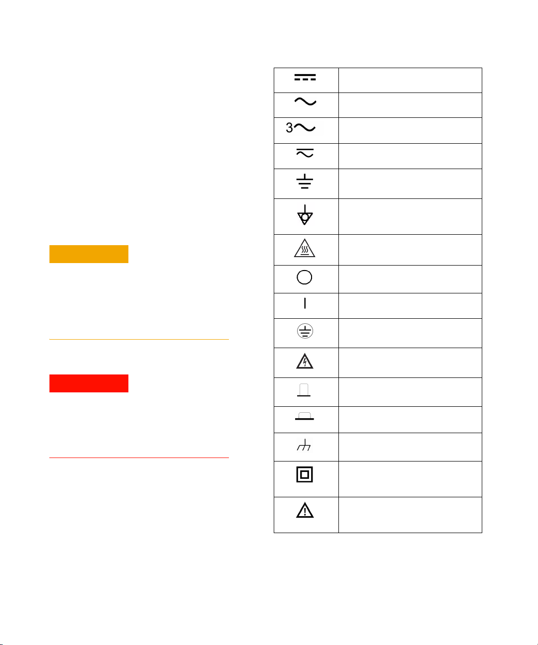
Safety Symbols
Direct current
Alternating current
Three-phase alternating current
Both direct and alternating current
Earth (ground) terminal
Equipotentiality
Caution, hot surface
A CAUTION notice denotes a hazard. It calls attention to an
operating procedure, practice, or the like that, if not correctly
performed or adhered to, could result in damage to the product or loss of important data. Do not proceed beyond a CAU-
TION notice until the indicated conditions are fully
understood and met.
WARNING notice denotes a hazard. It calls attention to an
operating procedure, practice, or the like that, if not correctly performed or adhered to, could result in personal
injury or death. Do not proceed beyond a WARNING notice
until the indicated conditions are fully understood and met.
Off (supply)
On (supply)
Protective conductor terminal
Caution, risk of electric shock
Out position of a bi-stable control
In position of a bi-stable control
Frame or chassis terminal
Equipment protected throughout by
double insulation or reinforced
insulation
Caution, risk of danger (refer to this
manual for specific Warning or Caution
information
1 U1701A Quick Start Guide
Page 3
CAUTION
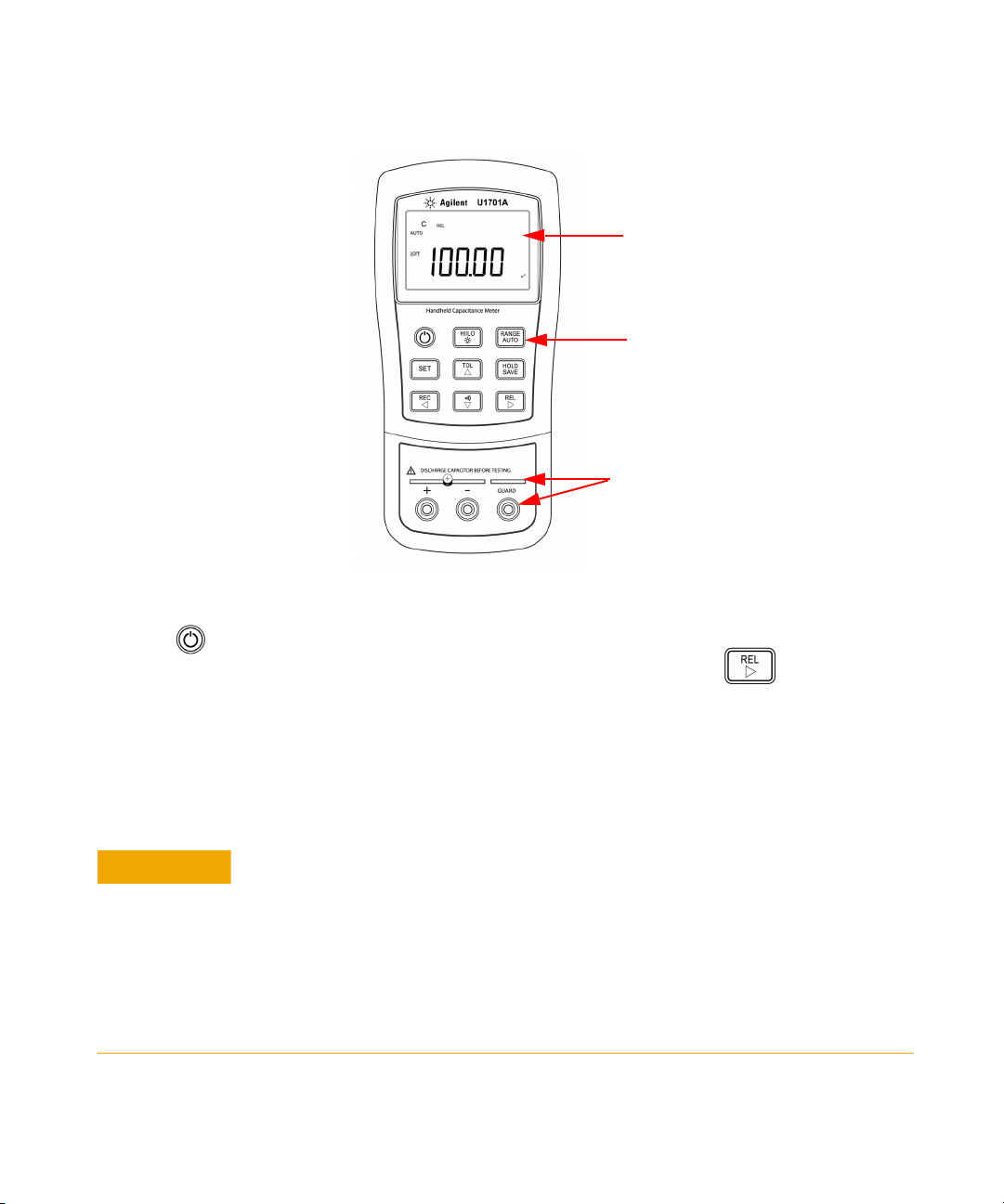
Annunciator Display
Keypad
Input Terminals
U1701A Dual Display Handheld Capacitance Meter
Quick Start
1 Press to power- on the meter.
2 To test for capacitance, keep an open circuit on the test leads and press to subtract the
residual capacitance of the meter and leads.
3 Insert the capacitor legs into + and – input terminals respectively. Ensure that the polarity of
the capacitor’s leg are correct.
4 Remove your hands from capacitor to allow it to be tested.
5 Read the measurement on the display.
U1701A Quick Start Guide 2
Measuring tip: For measuring capacitance of more than 1000 µF, first, discharge the
capacitor then select a suitable range to measure it. This will shorten the measuring
time to achieve an accurate value.
Degradation of some product specifications can occur in the presence of ambient
electromagnetic (EM) fields and noise that couples to the product’s powerline or I/O
cables. The product self-recovers and operates to all specifications when the source of
the ambient EM field and noise are removed or the product is protected from the
ambient EM field or the product cabling is shielded from the ambient EM noise.
Page 4
5
4
3
2
6
1
8
9
11
10
12
13
16
17
15
7
14
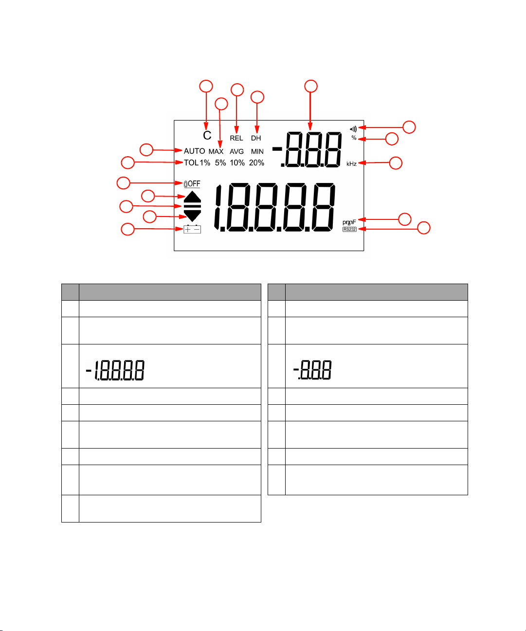
Display Annunciators
No. Descriptions No. Descriptions
1 Low battery indicator 10 Relative mode
2 Reading out of LO limit 11 Data hold to hold the displayed digital value. (DH
flashing means under trigger)
3 Primary display for capacitance measurement 12 Secondary display
4 Reading out of HI limit 13 Audible alert for tolerance and compare mode
5 Auto power off indicator 14 Unit for tolerance display
6 Tolerance mode, to set 1%, 5%, 10%, and 20% for
sorting capacitance
7 AUTO range 16 Unit for capacitance (pF, nF, µF, and mF)
8 Charging period will be flashed, display as
discharging period
9 Static recording mode for MAX, MIN, AVG and
Present (MAXAVGMIN)
15 Unit for Beeper Frequency as setup mode
17 Remote control
3 U1701A Quick Start Guide
Page 5
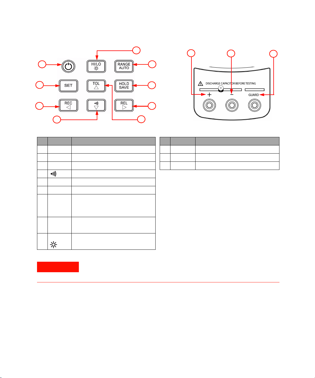
No. Keys Functions No. Te rm i n al s Functions
WARNING
8
5
4
1
2
3
9
7
6
Keypad Operations
10
12
11
Terminals
1 Power To turn ON/OFF the instrument 10 + Positive terminal
2 SET Set high/low limits for compare mode 11 – Negative terminal
3 REC Static recording mode 12 GUARD Guard terminal
4 Compare mode
5TOL Tolerance mode
6REL Relative mode
7 HOLD
SAVE
8RANGE
AUTO
9 HI/LO High/Low limits
Data hold
To store the setting value into the
memory
Manual range
Auto range
Backlight display
To avoid damaging this instrument, do not exceed the input limit. Do not apply
voltage to input terminals. Discharge the capacitor before testing.
U1701A Quick Start Guide 4
Page 6

Features and Functions
Actions Steps
To power ON or OFF Press
To enable data hold function Press
To trigger holding next reading Press momentarily
To exit data hold mode Press for more than 1 s
To enable recording function
• The beeper will beep when a new MAX or MIN value has
been recorded.
• The static recording captures stable values and updates
the memory. It will not record values that are overloaded,
OL or below 10 count value.
To cycle through maximum, minimum, average, and present
readings
•MAX, MIN, AVG or MAX AVG MIN annunciator will be
turned on respectively to indicate which value is being
displayed
To exit the recording mode Press for more than 1 s
To enable relative function
• Relative function shows the difference between the
measured value and the offset reference value. The
display may show a non-zero value due to the presence
of test leads. Use the relative function to nullify the
residual.
• Relative function can operate in both auto and manual
ranging mode but the function cannot be set when an
overload value exists.
•REL annuciator will be displayed.
To renew the relative value Press again
Press
Press momentarily
Press
To exit relative mode Press for more than 1 s
To select manual range and to turn off the AUTO
annunciator
To step up a range at a time Press again
Press
5 U1701A Quick Start Guide
Page 7

Actions Steps
To select auto-range
• In auto range mode, the AUTO annunciator is displayed
and the instrument will select an appropriate range for
resolution if the reading is greater than the maximum
available range. OL will be displayed.
• The instrument will select a lower range when the
reading is less than 9% of full scale.
To enable the tolerance mode and to set the display value
as a standard reference
•TOL annunciator will be displayed.
• The tolerance will be displayed on the secondary display.
• The instrument range will be locked.
To cycle through 1%, 5%, 10% and 20% tolerance
• will be indicated.
• Beeper will beep once if the test value is within the
selected tolerance. If the test value is out of the
tolerance, the beeper will beep three times.
• This mode cannot be enabled under the following
conditions:
• After setting the recording mode
• After setting the compare mode
• Display showing either OL or below 10 counts
To exit tolerance mode Press and hold for more than 1 s
Press for more than 1 s
Press
Press momentarily
To enable compare mode
• Measuring range will be locked
• will be displayed and the secondary display will
indicate C # #, meaning which set has been used for
compare mode. The two right digits indicate current
compare set. The # # range from 01 to 25.
• The primary display shows the present measurement. In
this state, it is ready for testing.
• If the reading is beyond the high limit, will be
indicated. will be indicated if the reading is out of the
low limit. The beeper will beep three times and the
secondary display will indicate nGo.
• If the reading is within the high and low limits, the beeper
will beep once, and the secondary display will indicate
Go. After three seconds or when the reading is lower
than 10 counts, the instrument will return to its ready
state.
• The secondary display will indicate C01 to C25 according
to the comparison record that has been selected.
Press
U1701A Quick Start Guide 6
Page 8
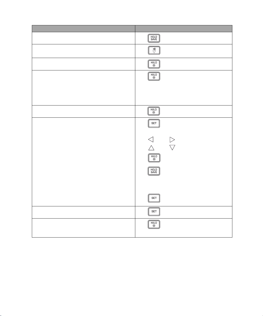
Actions Steps
To save comparison set for next entry Press and hold for more than 1 s
To exit compare mode Press
To view the High/Low limit value to be used as compare
mode
To cycle through HI limit, LO limit, and present values on
the primary display
• The secondary display showed as H # #, L # # and C #
# respectively.
• After three seconds without pressing this button again, it
will return to the present value display.
To toggle HI and LO limits for adjustment Press momentarily
To enter HI/LO limits setting mode
• The secondary display will flash H01 and the primary
display will indicate the value of HI limit.
• The following buttons will be used for this setting mode:
a To select which digit to be adjusted
b To increase or decrease the current digit’s value
c To select High or Low limit to be set.
d To store the setting value in the memory. The beeper will
beep twice if the selected value has been stored. If the
current setting do not meet the rule that the high limit
must be equal or greater than the low limit, the beeper
will beep three times.
e To select next compare setting. To cycle through L01 (or
H01) to L25 (or H25), then return to L01 (H01) setting.
Press momentarily
Press
Press for more than 1 s
Press (Left) or (Right)
Press (Up) or (Down)
Press
Press for more than 1 s
Press momentarily
To exit the HI/LO limit setting mode Press for more than 1 s
To toggle backlight ON/OFF
• Backlight turns off automatically after setting period by
setup mode.
Press and hold for more than 1 s
7 U1701A Quick Start Guide
Page 9

Power-On Options
To select power- on options, press and hold while turning the ON/OFF switch to ON
position. The power- on options are listed in Table 1- 1:
Tab l e 1 - 1 Power-On Options
Key Description
HOLD Demonstrate Annunciators
RANGE Fast power off test for factory’s purpose
REL To view the firmware revision
SET Setup Mode
To demonstrate the annunciators, the entire annunciators will
be displayed. Press any button to exit demonstration mode.
Reset the high and low limits to factory’s default values.
To configure related parameter, please refer to “How To Enter
Setup Mode”.
How to Enter Setup Mode
Press and hold and power on the instrument from OFF status. Release when
you hear a beep, the instrument will then enter setup mode. These parameters will be
remained in the non- volatile memory even after the instrument is turned off. To
configure the related parameters on setup mode, ensure that the following procedures are
followed:
1 Press (Left) or (Right) to select the menu item to be set.
2 Press (Up) or (Down) to change the parameter.
3 Press
4 Press and hold for more than 1 s to save your setting.
5 Press
U1701A Quick Start Guide 8
to select the digit to be adjusted, the selected digit will flash.
for more than 1 s to exit setup mode.
Page 10

Factory Default Settings
The following table below lists out the setup menu item and factory default settings.
Tab l e 1 - 2 Outline of Setup Menu Items
Menu Item Default Selectable Parameters
bAUd 9600 Baud rate: 2400, 4800, 9600, 19200
PArt none Parity: Odd, Even or None
Data 8-b 8 bits or 7 bits (Stop bit is always 1 bit)
Echo oFF Echo: on or oFF
Prnt oFF Print: on or oFF
beep 4800 Driving frequency: 4800, 2400, 1200, 600 Hz.
LbUt oFF Lock buttons
AoFF 15 1~99 minutes, oFF: To disable auto power-off
blit 30 1~99 seconds, oFF: To disable turning off backlight
oFF: To disable beep.
oFF: Enable keypad
on: Disable keypad
automatically
boFF oFF Backlight level of brightness at OFF state: oFF~09
bon 09 Backlight level of brightness at ON state: oFF~09
dEFA rSt Reset the above items to factory’s default setting.
9 U1701A Quick Start Guide
Page 11

General Specifications
Parameter U1701A
Power Supply Single standard 9 V battery (Alkaline)
(Power adaptor is available as optional accessories)
Display 4 ½-digit liquid crystal display (LCD) with maximum reading of 11,000
counts and automatic polarity indication
Function • Capacitance measurement by DC charge and discharge method
• Visible and audible Tolerance mode assists you to sort the capacitor
• Min/Max/Average, Data Hold with Manual or Auto Trigger and
Relative modes
• Comparison mode with 25 sets of HI/LO limits can be selected
• Backlit display for easy reading in the dark
• Bi-directional optic computer interface with SCPI commands
• One-year calibration cycle suggested
Measuring rate ~5 times/s for capacitance <100 µF (Typical)
Battery type Alkaline: ANSI/NEDA: 1604A / IEC: 6LR61
Power consumption 5.6 mA (Battery operation)
Battery life ~80 hours without backlight based on new alkaline
Operating temperature 0 °C to 50 °C
Storage temperature –20 °C to 60 °C
Storage humidity 0 – 80% R.H. non condensing
Relative Humidity (R.H.) 80% R.H.
Temperature coefficient 0.1 * (Specified Accuracy)/ °C (from 0 °C to 18 °C or 28 °C to 50 °C)
Low battery indicator will appear when the voltage drops below ~ 6.0 V
Weight 320 g
Dimension (W x L x H) 87 mm x 184 mm x 41 mm
Safety Designed in compliance with IEC 61010-1 for Pollution Degree 2
Standard accessories • Agilent U1701A Quick Start Guide, Agilent U1701A User’s and Service
Guide, and software application - included in the Product Reference
CD-ROM
• Agilent U1701A Quick Start Guide
• Alligator clip leads
• 9 V Alkaline Battery
• Certificate of Calibration
Optional accessories • IR to USB Cable (U5481A-FG)
• Power adaptor (U1780A-FG)
• SMD Tweezers (U1782-FG)
• Soft carrying case (U1174A-FG)
U1701A Quick Start Guide 10
Page 12

Electrical Specifications
Accuracy is given as ±(% of reading + counts of least significant digit) at 23 °C ±5 °C, with
relative humidity less than 80% R.H.
1
Range Resolution Accuracy
1000.0 pF 0.1 pF 1% + 10 5 times/s
10.000 nF 0.001 nF 1% + 5 5 times/s
100.00 nF 0.01 nF 0.5% + 3 5 times/s
1000.0 nF 0.1 nF 5 times/s
10.000 µF 0.001 µF 5 times/s
100.00 µF 0.01 µF 5 times/s
1000.0 µF 0.1 µF 0.86 times/s
10.000 mF 0.001 mF 1% + 5 0.13 times/s
199.99 mF 0.1 mF 2% + 5 0.006 times/s
* The accuracy is specified to measure film capacitor or better, and use relative mode to zero residual first.
*
Measuring rate as full
scale (approx.)
1 This specification is based on the measurement performed at the test socket.
11 U1701A Quick Start Guide
Page 13

U1701A Quick Start Guide 12
Page 14

www.agilent.com
Contact us
To obtain service, warranty or technical
support assistance, contact us at the following phone numbers:
United States:
(tel) 800 829 4444 (fax) 800 829 4433
Canada:
(tel) 877 894 4414 (fax) 800 746 4866
China:
(tel) 800 810 0189 (fax) 800 820 2816
Europe:
(tel) 31 20 547 2111
Japan:
(tel) 0120 (421) 345
Korea:
(tel) (080) 769 0800 (fax) (080) 769 0900
Latin America:
(tel) (305) 269 7500
Ta i w a n :
(tel) 0800 047 866 (fax) 0800 286 331
Other Asia Pacific Countries:
(tel) (65) 6375 8100 (fax) (65) 6755 0042
Or visit Agilent worldwide web at:
www.agilent.com/find/assist
Product specifications and descriptions in
this document subject to change without
notice.
© Agilent Technologies, Inc. 2008
Printed in Malaysia
First Edition, November 28, 2008
U1701-90017
Agilent Technologies
 Loading...