

Page 1

Agilent U1251A and
U1252A
Handheld Digital
Multimeter
User’s and Service Guide
Agilent Technologies
Page 2

Notices
CAUTION
WARNING
© Agilent Technologies, Inc. 2006 – 2012
No p art o f this manu al may be re produce d in
any form or by any means (including electronic storage and retrieval or translation
into a foreign language) without prior agreement and written consent from Agilent
Technologies, Inc. as governed by United
States and international copyright laws.
Manual Part Number
U1251-90003
Edition
Tenth Edition, May 4, 2012
Printed in Malaysia
Agilent Technologies, Inc.
3501 Stevens Creek Blvd.
Santa Clara, CA 95052 USA
Technology Licenses
The hardware and/or software described in
this document are furnished under a license
and may be used or copied only in accordance with the terms of such license.
Restricted Rights Legend
U.S. Government Restricted Rights. Software and technical data rights granted to
the federal government include only those
rights customarily provided to end user customers. Agilent provides this customary
commercial license in Software and technical data pursuant to FAR 12.211 (Technical
Data) and 12.212 (Computer Software) and,
for the Department of Defense, DFARS
252.227-7015 (Technical Data - Commercial
Items) and DFARS 227.7202-3 (Rights in
Commercial Computer Software or Computer Software Documentation).
Warranty
The material contained in this document is provided “as is,” and is subject to being changed, without notice,
in future editions. Further, to the maximum extent permitted by applicable
law, Agilent disclaims all warranties,
either express or implied, with regard
to this manual and any information
contained herein, including but not
limited to the implied warranties of
merchantability and fitness for a particular purpose. Agilent shall not be
liable for errors or for incidental or
consequential damages in connection with the furnishing, use, or performance of this document or of any
information contained herein. Should
Agilent and the user have a separate
written agreement with warranty
terms covering the material in this
document that conflict with these
terms, the warranty terms in the separate agreement shall control.
Accessories Warranty
Agilent offers warranty for product’s accessories for up to 3 months from the end-user
acceptance date.
Standard Calibration Service
(optional)
Agilent offers an optional calibration service
contract for a period of 3 years from
end-user acceptance date.
Safety Notices
A CAUTION notice denotes a hazard. It calls attention to an operating procedure, practice, or the like
that, if not correctly performed or
adhered to, could result in damage
to the product or loss of important
data. Do not proceed beyond a
CAUTION notice until the indicated
conditions are fully understood and
met.
A WARNING notice denotes a
hazard. It calls attention to an
operating procedure, practice, or
the like that, if not correctly performed or adhered to, could result
in personal injury or death. Do not
proceed beyond a WARNING
notice until the indicated conditions are fully understood and
met.
II Agilent U1251A/U1252A User’s and Service Guide
Page 3

Safety Symbols
CAT IV
600 V
The following symbols on the instrument and in the documentation indicate precautions which must be taken to
maintain safe operation of the instrument.
CAT III
1000 V
Category III 1000 V overvoltage protection Category IV 600 V overvoltage protection
Equipment protected throughout by
double insulation or reinforced
insulation
Caution, risk of danger (refer to this manual
for specific Warning or Caution information)
Earth (ground) terminal
Caution, risk of electric shock
Agilent U1251A/U1252A User’s and Service Guide III
Page 4

Safety Information
This meter is safety-certified in compliance with EN/IEC 61010-1:2001, UL 61010-1 Second Edition and CAN/CSA
22.2 61010-1 Second Edition, CAT III 1000 V/ CAT IV 600 V Overvoltage Protection, Pollution Degree II. Use with
standard or compatible test probes.
General Safety Information
The following general safety precautions must be observed during all phases of operation, service, and repair of
this instrument. Failure to comply with these precautions or with specific warnings elsewhere in this manual
violates safety standards of design, manufacture, and intended use of the instrument. Agilent Technologies
assumes no liability for the customer’s failure to comply with these requirements.
IV Agilent U1251A/U1252A User’s and Service Guide
Page 5

WARNING
• When working above 70 VDC, 33 VAC RMS or 46.7 V peak, exercise caution – such
range pose a shock hazard.
• Do not measure more than the rated voltage (as marked on the meter) between
terminals, or between terminal and earth ground.
• Double-check the meter’s operation by measuring a known voltage.
• For current measurement, turn off circuit power before connecting the meter to the
circuit. Always place the meter in series with the circuit.
• When connecting probes, always connect the common test probe first. When
disconnecting probes, always disconnect the live test probe first.
• Detach test probes from the meter before you open the battery cover.
• Do not use the meter with the battery cover or part of the cover removed or loose.
• Replace the battery as soon as the low battery indicator flashes on screen. This is
to avoid false readings, which may lead to possible electric shock or personal injury.
• Do not operate the product in an explosive atmosphere or in the presence of
flammable gases or fumes.
• Inspect the case for cracks or missing plastic. Pay extra attention to the insulation
surrounding the connectors. Do not use the meter if it is damaged.
• Inspect the test probes for damaged insulation or exposed metal, and check for
continuity. Do not use the test probe if it is damaged.
• Do not use any other AC charger adaptor apart from the one certified by Agilent with
this product.
• Do not use repaired fuses or short-circuited fuse-holders. For continued protection
against fire, replace the line fuses only with fuses of the same voltage and current
rating and recommended type.
• Do not service or perform adjustments alone. Under certain condition, hazardous
voltages may exist, even with the equipment switched off. To avoid dangerous electric
shock, service personnel must not attempt internal service or adjustment unless
another person, capable of rendering resuscitation or first aid, is present.
• Do not substitute parts or modify equipment to avoid the danger of introducing
additional hazards. Return the product to Agilent Technologies Sales and Service
Office for service and repair to ensure the safety features are maintained.
• Do not operate damaged equipment as the safety protection features built into this
product may have been impaired, either through physical damage, excessive
moisture, or any other reason. Remove power and do not use the product until safe
operation can be verified by service-trained personnel. If necessary, return the
product to Agilent Technologies Sales and Service Office for service and repair to
ensure the safety features are maintained.
Agilent U1251A/U1252A User’s and Service Guide V
Page 6

CAUTION
• Turn off the circuit power and discharge all high-voltage capacitors in the circuit before
you perform resistance, continuity, diodes, or capacitance tests.
• Use the correct terminals, function, and range for your measurements.
• Never measure voltage when current measurement is selected.
• Use only recommended rechargeable battery. Ensure proper insertion of battery in the
meter, and follow the correct polarity.
• Disconnect test leads from all the terminals during battery charging.
VI Agilent U1251A/U1252A User’s and Service Guide
Page 7

Regulatory Markings
The CE mark is a registered trademark
of the European Community. This CE
mark shows that the product complies
with all the relevant European Legal
Directives.
The C-tick mark is a registered
trademark of the Spectrum
Management Agency of Australia. This
signifies compliance with
the Australia EMC Framework
regulations under the terms of the
Radio Communication Act of 1992.
ICES/NMB-001 indicates that this ISM
device complies with the Canadian
ICES-001.
Cet appareil ISM est confomre a la
norme NMB-001 du Canada.
The CSA mark is a registered
trademark of the Canadian Standards
Association.
This instrument complies with the
WEEE Directive (2002/96/EC) marking
requirement. This affixed product label
indicates that you must not discard
this electrical/electronic product in
domestic household waste.
Agilent U1251A/U1252A User’s and Service Guide VII
Page 8
Waste Electrical and Electronic Equipment (WEEE) Directive 2002/96/EC
This instrument complies with the WEEE Directive (2002/96/EC) marking
requirement. This affixed product label indicates that you must not discard
this electrical/electronic product in domestic household waste.
Product Category:
With reference to the equipment types in the WEEE directive Annex 1, this
instrument is classified as a “Monitoring and Control Instrument” product.
The affixed product label is as shown below.
Do not dispose in domestic household waste
To return this unwanted instrument, contact your nearest Agilent
Technologies, or visit: www.agilent.com/environment/product for more
information.
Agilent Technologies, through Rechargeable Battery Recycling Corporation (RBRC), offers free and convenient
battery recycling options in the U.S. and Canada. Contact RBRC at 877-2-RECYCLE (877.273.2925) or online at:
http://www.call2recycle.org/ for the nearest recycling location.
VIII Agilent U1251A/U1252A User’s and Service Guide
Page 9

In This Guide…
1Getting Started
This chapter contains information on the Agilent U1251A and U1252A
handheld multimeter front panel, rotary switch, keypad, display, terminals
and rear panel.
2 Making Measurements
This chapter contains information on how to make measurements using
the U1251A and U1252A handheld digital multimeter.
3 Functions and Features
This chapter contains information on the functions and features that are
available for the U1251A and U1252A digital multimeter.
4 Changing The Default Setting
This chapter shows you how to change the default factory settings of the
U1251A and U1252A and other available setting options
5 Maintenance
This chapter will go through how to troubleshoot the handheld digital
multimeter if any problems arise.
6 Performance Tests and Calibration
This chapter contains the performance test and the adjustment procedure.
7 Specifications
This chapter lists the product characteristics, specification assumptions
and the specifications of the U1251A and U1252A digital multimeters.
Agilent U1251A/U1252A User’s and Service Guide IX
Page 10

Declaration of Conformity (DoC)
NOTE
The Declaration of Conformity (DoC) for this instrument is available on the
Web site. You can search the DoC by its product model or description.
http://regulations.corporate.agilent.com/DoC/search.htm
If you are unable to search for the respective DoC, please contact your
local Agilent representative.
X Agilent U1251A/U1252A User’s and Service Guide
Page 11

Contents
1 Getting Started
Introducing the U12521A/U1252A Handheld Digital Multimeter 2
Check the shipment 3
Adjusting the tilt-stand 4
The rear panel at a glance 7
The keypad at a glance 9
The display at a glance 11
Selecting display with the Hz button 16
Selecting display with the Dual button 18
Selection display with the Shift button 20
The terminals at a glance 22
2 Making Measurements
Understanding The Measurement Instructions 24
III
Measuring Voltage 24
Measuring AC voltage 25
Measuring DC voltage 26
Measuring Current 27
µA & mA measurement 27
Percentage scale of 4 mA to 20 mA 29
A (ampere) measurement 31
Frequency Counter 32
Measuring Resistance, Conductance and Testing Continuity 34
Tes ti ng Dio de s 38
Measuring Capacitance 41
Measuring Temperature 43
Alerts and Warning During Measurement 47
Abbreviated Book Title Variable (Edit this) XIII
Page 12

III
Overload alert 47
Input warning 47
Charge terminal alert 48
3 Functions and Features
Dynamic Recording 50
Data Hold (Trigger Hold) 52
Refresh Hold 53
Null (Relative) 55
Decibel Display 57
1 ms Peak Hold 59
Data Logging 61
Manual logging 61
Interval logging 63
Reviewing logged data 65
Square Wave Output (for U1252A) 67
Remote Communication 71
4 Changing The Default Setting
Selecting Setup Mode 74
Setting Data Hold/Refresh Hold Mode 77
Setting Data Logging Mode 78
Setting Thermocouple Types (U1252A only) 79
Setting Reference Impedance for dBm Measurement 80
Setting Minimum Frequency Measurement 81
Setting Temperature Unit 82
Setting Auto Power Saving Mode 84
Setting Percentage (%) Scale Readout 86
XIV Abbreviated Book Title Variable (Edit this)
Page 13

Setting Beep Frequency 87
Setting Backlight Timer 88
Setting Baud Rate 89
Setting Parity Check 90
Setting Data Bit 91
Setting Echo Mode 92
Setting Print Mode 93
Returning to Default Factory Settings 94
5 Maintenance
Introduction 96
General maintenance 96
Battery replacement 96
Storage considerations 98
Charging the battery 98
Fuse checking procedure 105
Replacing the fuse 106
Troubleshooting 108
III
Replaceable Parts 109
To order replaceable parts 109
6 Performance Tests and Calibration
Calibration Overview 112
Closed-case electronic calibration 112
Agilent Technologies calibration services 112
Calibration interval 113
Adjustment is recommended 113
Recommended Test Equipment 114
Basic Operating Test 115
Backlit test 115
Abbreviated Book Title Variable (Edit this) XV
Page 14

III
Testing the display 115
Current terminal test 116
Charge terminal alert test 117
Test Considerations 118
Calibration Security 119
Performance Verification Tests 120
Unsecuring the instrument for calibration 128
Calibration process 131
Using the front panel for adjustments 132
Adjustments Consideration 133
Valid adjustment input values 134
Adjustment procedure 135
Finishing the adjustment 142
To read the calibration count 142
Calibration errors 143
7 Specifications
Product Characteristics 146
Measurement Category 149
Measurement category definition 149
Specification Assumptions 150
Electrical Specifications 151
DC Specifications 151
AC Specifications 153
AC+DC Specifications for U1252A 155
Capacitance Specifications 156
Temperature Specifications 156
Frequency Specifications 157
Duty Cycle and Pulse Width Specifications 157
Frequency Sensitivity Specifications 158
XVI Abbreviated Book Title Variable (Edit this)
Page 15

Peak Hold Specifications 159
Frequency Counter Specifications for U1252A 160
Square Wave Output for U1252A 161
Operating Specifications 162
Display update rate (approximate) 162
Input impedance 163
III
Abbreviated Book Title Variable (Edit this) XVII
Page 16

III
XVIII Abbreviated Book Title Variable (Edit this)
Page 17

List of Figures
Figure 1-1 Tilt-stand at 60° 4
Figure 1-2 Tilt-stand at 30° 4
Figure 1-3 Tilt-stand at hanging position 5
Figure 1-4 U1252A front panel 6
Figure 1-5 Rear panel 7
Figure 1-6 Rotary switch 8
Figure 1-7 U1252A keypad 9
Figure 1-8 Display symbols 11
Figure 1-9 U1252A connector terminals 22
Figure 2-1 Measuring AC voltage 25
Figure 2-2 Measuring DC voltage 26
Figure 2-3 Measuring mA and mA current 28
Figure 2-4 Measuring scale of 4-20 mA 30
Figure 2-5 A (ampere) current measurement 31
Figure 2-6 Measuring frequency 33
Figure 2-7 Measuring resistance 34
Figure 2-8 Audible continuity, conductance, and resistance
test. 35
Figure 2-9 Conductance measurement 37
Figure 2-10 Measuring forward bias of diode 39
Figure 2-11 Measuring reverse bias of diode 40
Figure 2-12 Capacitance measurements 42
Figure 2-13 Connecting the thermal probe into the non-compensa-
tion transfer adapter 44
Figure 2-14 Connecting the probe with adapter into the
multimeter 44
Figure 2-15 Surface temperature measurement 46
Figure 2-16 Input terminal warning 47
Figure 2-17 Charge terminal alert 48
Figure 3-1 Dynamic recording mode operation 51
Figure 3-2 Data hold mode operation 52
Figure 3-3 Refresh hold mode operation 54
Figure 3-4 Null (relative) mode operation 56
Figure 3-5 dBm/dBV display mode operation 58
Figure 3-6 1 ms peak hold mode operation 60
Figure 3-7
Hand (Manual) logging mode operation 62
Abbreviated Book Title Variable (Edit this) IX
Page 18

Figure 3-8 Full Log 62
Figure 3-9 Interval (Automatic) logging mode operation 64
Figure 3-10 Log review mode operation 66
Figure 3-11 Frequency adjustment for square wave output 68
Figure 3-12 Pulse width adjustment for square wave output 69
Figure 3-13 Duty cycle adjustment for Square Wave 70
Figure 3-14 Cable connection for remote communication 71
Figure 4-1 Data hold/Refersh hold setup 77
Figure 4-2 Data logging setup 78
Figure 4-3 Thermocouple type setup 79
Figure 4-4 Reference impedance for dBm measurement setup 80
Figure 4-5 Minimum frequency setup 81
Figure 4-6 Temperature unit setup 83
Figure 4-7 Auto power saving setup 85
Figure 4-8 % scale readout setup 86
Figure 4-9 Beep frequency setup 87
Figure 4-10 Backlit timer setup 88
Figure 4-11 Baud rate setup remote control 89
Figure 4-12 Parity check setup 90
Figure 4-13 Data bit setup for remote control 91
Figure 4-14 Echo mode setup for remote control 92
Figure 4-15 Print mode setup for remote control 93
Figure 4-16 Reset setup 94
Figure 5-1 9 V rectangular battery 97
Figure 5-2 Battery capacity display as trickle 100
Figure 5-3 Self-test 100
Figure 5-4 Charging mode 102
Figure 5-5 Charge end and trickle state 103
Figure 5-6 Battery charging procedure 104
Figure 5-7 Fuse replacement 107
Figure 6-1 LCD display 115
Figure 6-2 Input warning 116
Figure 6-3 Charge terminal alert 117
X Abbreviated Book Title Variable (Edit this)
Page 19

List of Tables
Ta b l e 1 - 1 Rotary switch description and functions 8
Ta b l e 1 - 2 Keypad desciption and functions 9
Ta b l e 1 - 3 General display symbols 12
Ta b l e 1 - 4 Priamry display symbols 13
Ta b l e 1 - 5 Secondary display symbols 14
Ta b l e 1 - 6 Analog bar range and counts 15
Ta b l e 1 - 7 Selecting display with the Hz button 16
Ta b l e 1 - 8 Selecting display with the Dual button 18
Ta b l e 1 - 9 Selecting display with the Shift button 20
Ta b l e 1 - 1 0 Terminal connections for different measuring
functions 22
Ta b l e 2 - 1 Numerical steps descriptions 24
Ta b l e 2 - 2 Percentage scale and measurement range 29
Ta b l e 2 - 3 Audible continuity measurement range 36
Ta b l e 4 - 1 Available setting options in Setup mode 75
Ta b l e 5 - 1 Battery voltage and corresponding percentage of charg-
es in standby and charging modes 100
Ta b l e 5 - 2 Error messages 101
Ta b l e 5 - 3 Measurement readings for fuse checking 106
Ta b l e 5 - 4 Fuse specifications 107
Ta b l e 5 - 5 Basic troubleshooting procedures 108
Ta b l e 6 - 1 Recommended Test Equipment 114
Ta b l e 6 - 2 Performance verification test steps 121
Ta b l e 6 - 3 Valid adjustment input values 134
Ta b l e 6 - 4 Adjustment table 137
Ta b l e 7 - 1 DC Accuracy ± (% of reading + Number of Least Signifi-
cant Digit) 151
Ta b l e 7 - 2 U1251A accuracy specifications ± (% of reading + num-
ber of LSD) for true RMS AC voltage 153
Ta b l e 7 - 3 U1251A accuracy specifications ± (% of reading + num-
ber of LSD) for true RMS AC current 153
Ta b l e 7 - 4 U1252A accuracy specifications ± (% of reading + num-
ber of LSD) for true RMS AC voltage 154
Ta b l e 7 - 5 U1252A accuracy specifications ± (% of reading + num-
ber of LSD) for true RMS AC current 154
Ta b l e 7 - 6 U1252A true RMS ac+dc voltage specifications 155
II
Abbreviated Book Title Variable (Edit this) XI
Page 20

II
Ta b l e 7 - 7 U1252A true RMS ac+dc current specifications 155
Ta b l e 7 - 8 Capacitance specifications 156
Ta b l e 7 - 9 Temperature specifications 156
Ta b l e 7 - 1 0 Frequency specifications 157
Ta b l e 7 - 1 1 Duty cycle and pulse width specifications 157
Ta b l e 7 - 1 2 Frequency sensitivity and trigger level specifications for
voltage measurements 158
Ta b l e 7 - 1 3 Frequency sensitivity specifications for current
measurements 159
Ta b l e 7 - 1 4 Peak hold specifications for dc voltage and current
measurements 159
Ta b l e 7 - 1 5 Frequency counter (divide by 1) specifications 160
Ta b l e 7 - 1 6 Frequency counter (divide by 100
specifications 160
Ta b l e 7 - 1 7 Square wave output specifications 161
Ta b l e 7 - 1 8 Display update rate (approximate) 162
Ta b l e 7 - 1 9 Input Impedance 163
[4]
)
XII Abbreviated Book Title Variable (Edit this)
Page 21

Agilent U1251A and U1252A Handheld Digital Multimeter
User’s and Service Guide
1
Getting Started
Introducing the U12521A/U1252A Handheld Digital Multimeter 2
Check the shipment 3
Adjusting the tilt-stand 4
The front panel at a glance 6
The rear panel at a glance 7
The rotary switch at a glance 8
The keypad at a glance 9
The display at a glance 11
Selecting display with the Hz button 16
Selecting display with the Dual button 18
Selection display with the Shift button 20
The terminals at a glance 22
This chapter contains information on the Agilent U1251A
and U1252A handheld multimeter front panel, rotary switch,
keypad, display, terminals and rear panel.
Agilent Technologies
1
Page 22

1 Getting Started Tutorial
Introducing the U12521A/U1252A Handheld Digital Multimeter
Key features of this digital multimeter:
• DC, AC, and AC + DC (U1252A only) voltage and current
measurements.
• True- RMS measurement for both AC voltage and current
• Rechargeable Ni- MH battery with built- in charging
capability (U1252A only)
• Ambient temperature on second display
• Battery capacity indicator
• Blue LED backlight
• Resistance measurement of up to 50 MΩ (for U1251A)
and 500 MΩ (for U1252A)
• Conductance measurement from 0.01 nS (100 GΩ)
• Capacitance measurement of up to 100 mF
• Frequency counter up of to 20 MHz (U1252A only)
•
The % scale readout for 4–20 mA or 0–20 mA measurement
• dBm with selectable reference impedance
• 1 ms Peak Hold to catch inrush voltage and current easily
• Temperature test with selectable 0
(without ambient temperature compensation).
• K- type (for U1251A) and J/K-types temperature
measurement (for U1252A)
• Frequency, duty cycle, and pulse width measurements
• Dynamic Recording for min, max, and average readings
• Data Hold with manual or auto trigger and Null mode
• Diode and audible continuity tests
• Square wave generator with selectable frequency, pulse
width and duty cycle (U1252A only)
• Agilent GUI Application Software (IR- USB cable sold
separately)
• Closed case calibration
°C compensation
~ 50 nS
2 Agilent U1251A/U1252A User’s and Service Guide
Page 23

Check the shipment
Getting Started Tutorial 1
Verify that you have received the following items with your
multimeter:
• 9 V alkaline battery (for U1251A only)
• Soft carrying case
• 4 mm probes
• Test leads
• Alligator clips
• SMT grabbers
• Fine tips test probes
• Mini grabber (black only)
• Rechargeable 7.2 V battery (for U1252A only)
• Power cord & AC adapter (for U1252A only)
• Quick Start Guide
• CD containing the User’s Guide, application software and
instrument drivers
• Certificate of Calibration
Contact your nearest Agilent Sales Office if any of the above
are missing.
Inspect the shipping containing for damage. Signs of damage
may include a dented or torn shipping container or
cushioning material that indicates signs of unusual stress or
compacting. Save the packaging material in case the
multimeter needs to be returned.
Please refer to the Agilent Handheld Tools brochure
(5989- 7340EN) for the full and latest list of handheld
accessories available.
Agilent U1251A/U1252A User’s and Service Guide 3
Page 24
1 Getting Started Tutorial
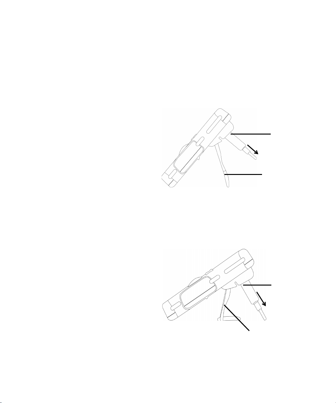
Adjusting the tilt-stand
To adjust the meter to a 60° standing position, pull the
tilt- stand outwards to its maximum reach.
IR-USB cable
To P C (h ost )
Tilt-stand at 60 °
Figure 1-1 Tilt-stand at 60
To adjust the meter to a 30° standing position, bend the tip
of the stand so that it is parallel to the ground before
pulling the stand outwards to its maximum reach.
Figure 1-2 Tilt-stand at 30
4 Agilent U1251A/U1252A User’s and Service Guide
°
IR-USB cable
To P C (h ost )
Tilt-stand at 30 °
°
Page 25
Getting Started Tutorial 1
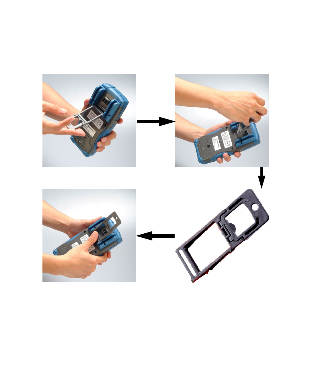
3. Flip the tilt-stand over until
this side of the
stand is facing the device instead of
facing you.
2. Detach the tilt-stand
1. Extend the tilt-stand until its
maximum reach
4. Re-attach the tilt-stand to an
upright position
To adjust the meter to a hanging position follow the steps
shown in Figure 1- 3 below.
Agilent U1251A/U1252A User’s and Service Guide 5
Figure 1-3 Tilt-stand at hanging position
Page 26
1 Getting Started Tutorial
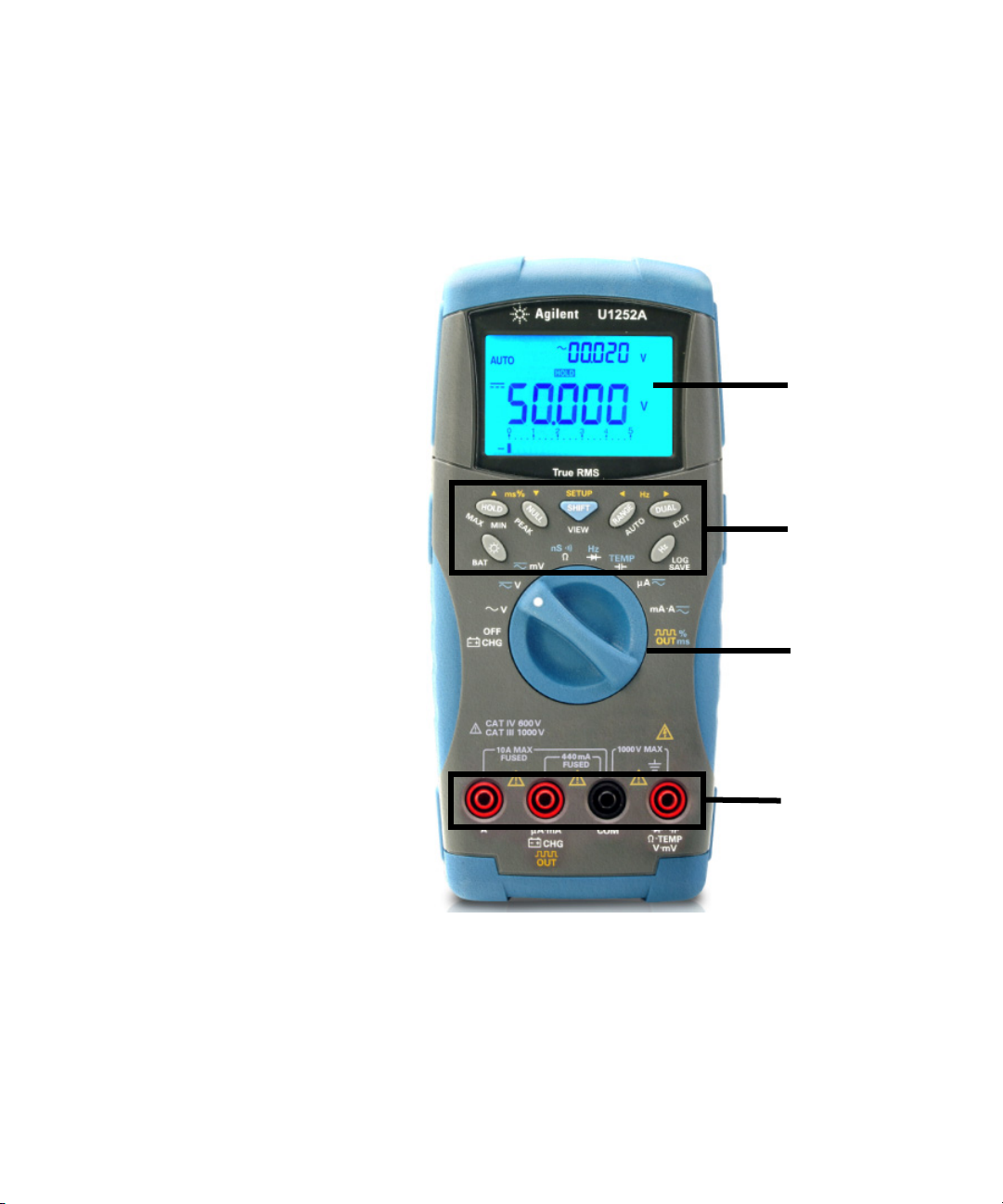
The front panel at a glance
Display
Keypad
Rotary switch
Te r m i n a l
Connectors
Figure 1-4 U1252A front panel
6 Agilent U1251A/U1252A User’s and Service Guide
Page 27
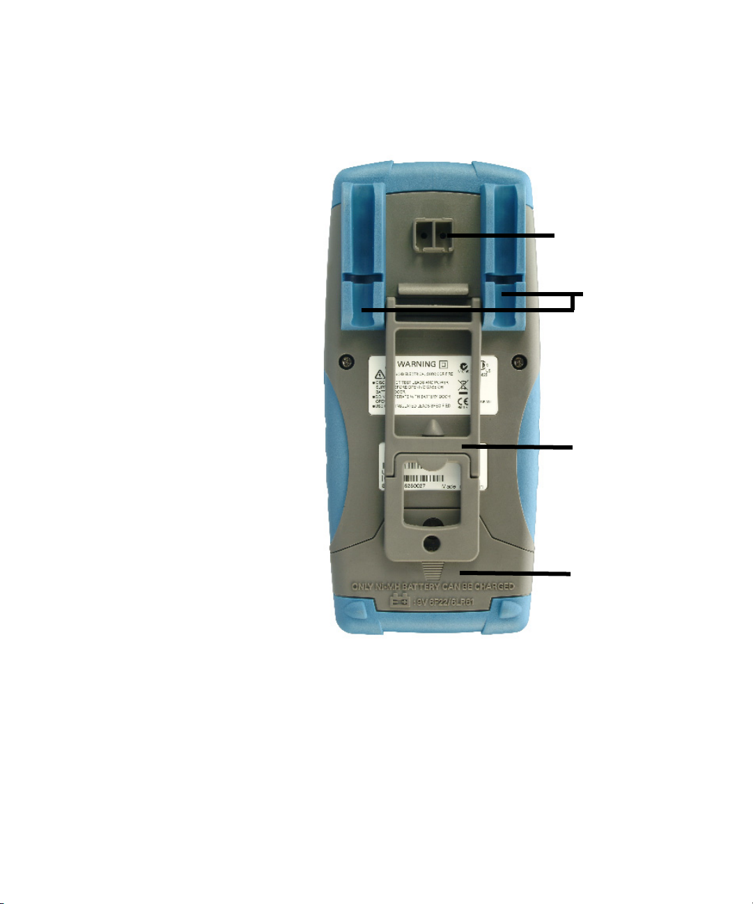
The rear panel at a glance
Getting Started Tutorial 1
IR communication port
Tes t pr obe
holders
Tilt-stand
Battery access
cover
Figure 1-5 Rear panel
Agilent U1251A/U1252A User’s and Service Guide 7
Page 28

1 Getting Started Tutorial
1
2
3
4
5
6
7
8
9
10
The rotary switch at a glance
Figure 1-6 Rotary switch
Tab l e 1 - 1 Rotary switch description and functions
No. Description/Function
1Charge mode (U1252A only) or OFF
2 AC voltage
3 AC voltage, DC voltage or DC+AC voltage (U1252A only)
4 DC mV, AC mV, AC+DC mV (U1252A only)
5 Resistance (Ω), Continuity, and Conductance ( nS )
6 Frequency counter (U1252A only) or Diode
7 Capacitance or Temperature
8 DC µA, AC µA, and AC+DC µA
8 Agilent U1251A/U1252A User’s and Service Guide
9 DC mA, DC current, AC mA, AC current, or AC+DC current
10 Square-wave output, Duty cycle, or Pulse width output (for
U1252A) and OFF (for U1251A)
Page 29
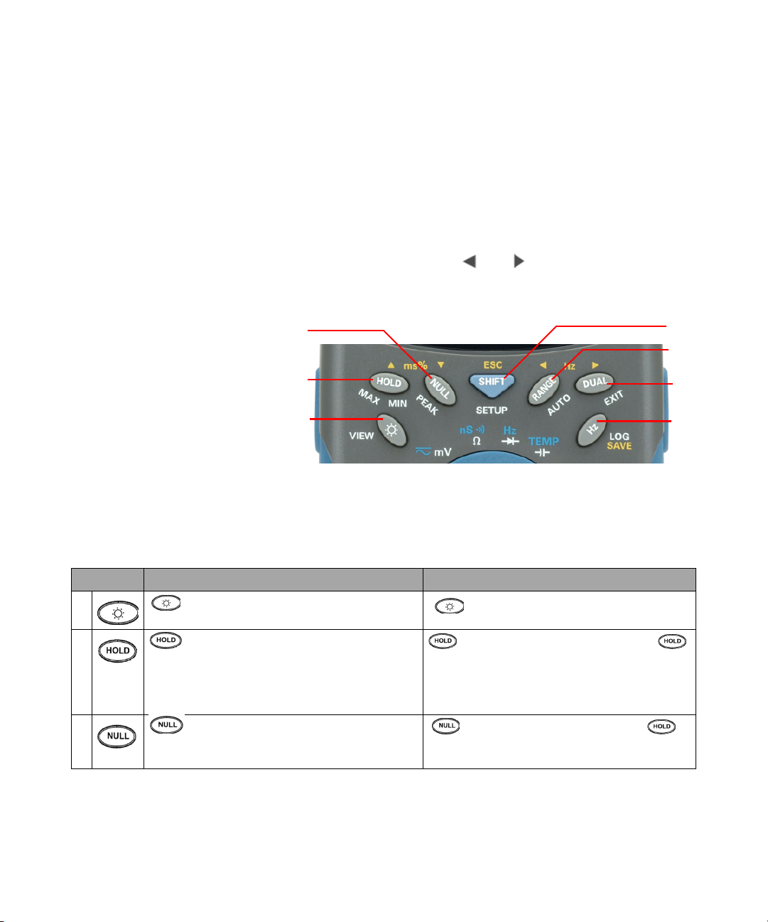
The keypad at a glance
1
2
3
4
5
6
7
The operation of each key is shown below. Pressing a key
illuminates a related symbol on the display and emits a beep
from the multimeter. Turning the rotary switch to another
position resets the current operation of the key.
Figure 1- 7 below shows the keypad of the U1252A. The ms%
(Pulse width/Duty cycle), Hz , and frequency counter
functions are only available on the U1252A.
Getting Started Tutorial 1
Figure 1-7 U1252A keypad
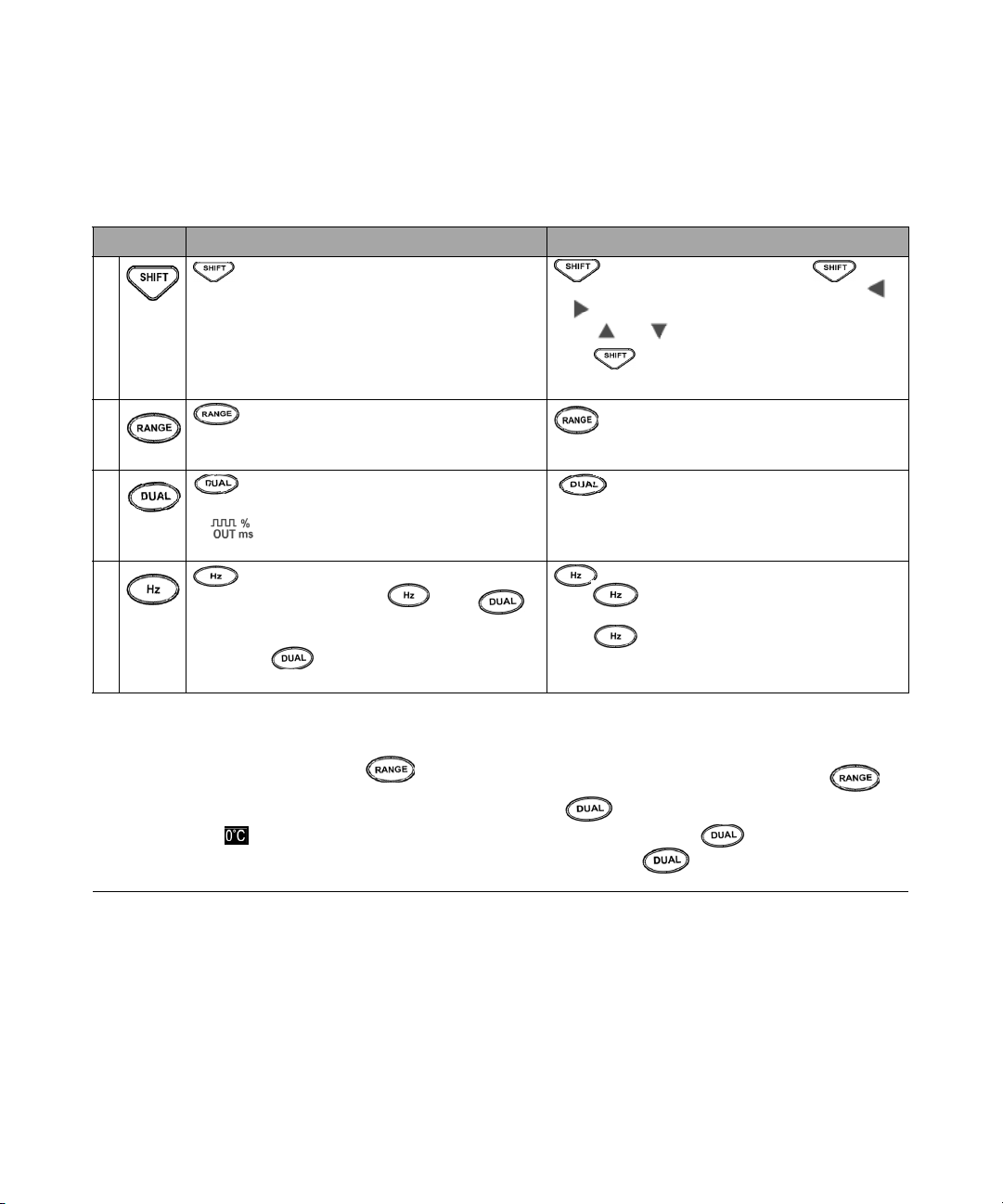
Tab l e 1 - 2 Keypad desciption and functions
Button Function when pressed for less than 1 second Function when pressed for more than 1 second
1 acts as a toggle switch to turn backlit ON/OFF.
Backlit automatically turns off after 30s (default)
2 freezes the measured value. In Data Hold
mode, press again to trigger hold of the next measured
value. In Refresh Hold mode, reading updates
automatically once reading is stable and count setting
is exceeded
3 saves displayed value as a reference to be
subtracted from subsequent measurements. Press
again to see the relative value that has been saved.
[1]
.
displays the battery capacity for 3 seconds.
[1]
.
enters Dynamic Recording mode. Press
again to scroll through Max, Min, Avg, and present
readings (indicated by MAXMINAVG on display).
enters 1 ms Peak Hold mode. Press
to scroll through Max and Min peak readings.
Agilent U1251A/U1252A User’s and Service Guide 9
Page 30
1 Getting Started Tutorial
Button Function when pressed for less than 1 second Function when pressed for more than 1 second
4 scrolls through the measuring function(s) at a
particular rotary switch position.
enters Log Review mode. Press to
switch to manual or interval logging data. Press
or to view first or last logged data respectively.
Press or to scroll up or down logged data.
Press for more than 1 second to exit mode.
5 scrolls through available measuring ranges
(except when rotary switch is set at TEMP or at Hz [for
U1252A] position)
[2]
.
6 scrolls through available dual-combination
displays (except when rotary switch is set at TEMP, Hz
or [for U1252A] position, or when meter is in
1 ms peak hold or dynamic recording mode)
[3]
.
7 enters Frequency Test mode for current or
voltage measurements. Press to scroll through
frequency (Hz), duty cycle (%) and pulse width (ms)
functions. In duty cycle (%) and pulse width (ms)
tests, press to switch to positive or negative
sets to Auto Range mode.
exits Hold, Null, Dynamic Recording, 1 ms
Peak Hold and dual display modes.
enters logging mode. In manual data logging,
press to log data manually into memory. In
automatic data logging, data logs automatically
[1]
.
Press for more than 1 second to exit auto data
logging mode.
pulse.
Notes for keypad descriptions and functions:
1 See Ta b l e 4 - 1 on page 75, “Available setting options in Setup mode,” for details of available options.
2 When rotary switch is at TEMP, press to switch to ºC or ºF display. When rotary switch is at Hz, press to
switch to division of signal frequency by 1 or 100.
3 When rotary switch is at TEMP, ETC is ON by default. You may press to disable ETC (Environment Temperature
Compensation), will appear on display. For pulse and duty cycle measurement, press to switch trigger slope
to positive or negative. When meter is in peak or dynamic-recording mode, press to restart 1 ms peak hold or
dynamic recording mode.
10 Agilent U1251A/U1252A User’s and Service Guide
Page 31

The display at a glance
To view the full display (with all segments illuminated),
press and hold the button while turning the rotary
switch from OFF to any non- OFF position. After you have
finished viewing the full display, press any button to resume
normal functionality based on the rotary switch position.
This is followed by a wake- up feature.
The meter will then enter power save mode once auto power
off (APF) is enabled. To wake the meter up:
1 Turn the rotary switch to OFF position then ON again.
2 Press any button for rotary switch position that is not at
square wave output position. (U1252A only)
3 To set the rotary switch at square wave out position,
press only the Dual, Range and Hold buttons or turn the
rotary switch to another position. (U1252A only)
The LCD signs are explained in the following tables.
Getting Started Tutorial 1
Figure 1-8 Display symbols
Agilent U1251A/U1252A User’s and Service Guide 11
Page 32

1 Getting Started Tutorial
Tab l e 1 - 3 General display symbols
LCD symbol Description
Remote control
Thermocouple types: (K-type) (J-type)
NULL Null math function
Diode / Audible continuity
Audible continuity for resistance
View mode for checking logged data
Data logging indication
Square wave output (U1252A only)
• Positive slope for pulse width (ms) and duty cycle (%) measurement
• Charging capacitor as capacitance measurement
• Negative slope for pulse width (ms) and duty cycle (%) measurement
• Discharging capacitor as capacitance measurement
Low battery indication
Auto power off enable
Refresh (auto) Hold
TRIG
MAXMINAVG Dynamic Recording mode: Present value on primary display
MAX Dynamic Recording mode: Maximum value on primary display
MIN Dynamic Recording mode: Minimum value on primary display
AVG
MAX
MIN
Trigger (manual) Hold
Dynamic Recording mode: Average value on primary display
1 ms Peak Hold mode: Positive peak value on primary display
1 ms Peak Hold mode: Negative peak value on primary display
12 Agilent U1251A/U1252A User’s and Service Guide
Page 33

Tab l e 1 - 4 Priamry display symbols
LCD symbol Description
Auto range
AC + DC
DC
AC
Polarity, digits, and decimal points for primary display
Getting Started Tutorial 1
The primary display signs are explained below.
dBm
dBV
MkHz
MkΩ Resistance units: Ω, kΩ, MΩ
nS
mV
µmA
%
ms
µmnF
ºC
ºF
%
%
Decibel unit relative to 1 mW
Decibel unit relative to 1 V
Frequency units: Hz, kHz, MHz
Conductance unit
Voltage units: mV, V
Current units: µA, mA, A
Duty cycle measurement
Pulse width unit
Capacitance units: nF, µF, mF
Celsius temperature unit
Fahrenheit temperature unit
Percentage scale readout proportional to DC 0–20 mA
Percentage scale readout proportional to DC 4–20 mA
Agilent U1251A/U1252A User’s and Service Guide 13
Page 34

1 Getting Started Tutorial
The secondary display signs are explained below.
Tab l e 1 - 5 Secondary display symbols
LCD symbol Description
AC + DC
DC
AC
Polarity, digits and decimal points for secondary display
kHz Frequency units: Hz, kHz
No ambient temperature compensation, just thermocouple measurement
ºC
ºF
mV
µmA
s
Celsius ambient temperature unit
Fahrenheit ambient temperature unit
Voltage units: mV, V
Current units:
Elapsed time unit: s (second) for Dynamic Recording and 1 ms Peak Hold modes
µA, mA, A
The analog bar emulates the needle on an analog multimeter,
without displaying the overshoot. When measuring peak or
null adjustments and viewing fast- changing inputs, the bar
graph provides a useful indication because it has quicker
update rate for fast response applications.
The bar graph is not used for square wave output, frequency,
duty cycle, pulse width, 4–20 mA% scale, 0–20 mA% scale
and temperature measurements. When frequency, duty cycle,
and pulse width are indicated on the primary display during
voltage or current measurement, the bar graph represents
the voltage or current value. When 4–20 mA% scale or
0–20 mA% scale is indicated on the primary display, the bar
graph represents the current value and not the percentage.
14 Agilent U1251A/U1252A User’s and Service Guide
Page 35

Tab l e 1 - 6 Analog bar range and counts
Range Counts/segments Used for the function
Getting Started Tutorial 1
The “+” or “–” sign is indicated when the positive or
negative value has been measured or calculated. Each
segment represents 2500 or 500 counts depending on the
range indicated on the peak bar graph. See the Table 1- 6
below.
2500 V, Ω, Diode
2500 V, A, Ω
2500 V, A, Ω, nS
500
V,
500
500
Agilent U1251A/U1252A User’s and Service Guide 15
Page 36
1 Getting Started Tutorial
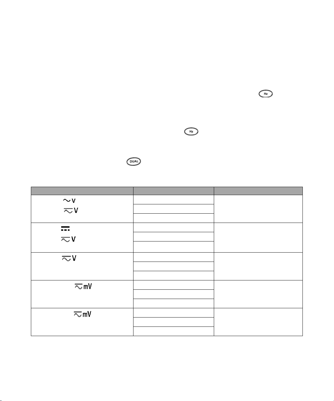
Selecting display with the Hz button
The frequency measurement feature helps to detect the
presence of harmonic currents in neutral conductors and
determines whether these neutral currents are the result of
unbalanced phases or non- linear loads. Press to access
the frequency measurement mode for current or voltage
measurements — voltage or current on the secondary display
and frequency on the primary display. Alternatively, pulse
width (ms) or duty cycle (%) can appear on the primary
display by pressing again. This enables the
simultaneous monitoring of real- time voltage and current
with frequency, duty cycle, or pulse width. Voltage or
current resumes on primary display after you press and hold
for more than 1 second.
Tab l e 1 - 7 Selecting display with the Hz button
Rotary switch position (Function) Primary display Secondary display
for U1252A
(AC voltage)
V for U1251A
for U1252A
(DC voltage)
for U1252A
(AC + DC voltage)
(AC voltage)
(DC voltage)
Frequency (Hz) AC V
Pulse width (ms)
Duty cycle (%)
Frequency (Hz) DC V
Pulse width (ms)
Duty cycle (%)
Frequency (Hz) AC + DC V
Pulse width (ms)
Duty cycle (%)
Frequency (Hz) AC mV
Pulse width (ms)
Duty cycle (%)
Frequency (Hz) DC mV
Pulse width (ms)
Duty cycle (%)
16 Agilent U1251A/U1252A User’s and Service Guide
Page 37

Tab l e 1 - 7 Selecting display with the Hz button (continued)
Frequency (Hz) AC + DC mV
(AC + DC voltage)
[for U1252A]
(AC Current)
(DC current)
(AC + DC current)
[for U1252A]
(AC current)
(DC current)
[for U1252A]
(AC + DC current)
Hz (Frequency counter) - press
to select frequency division by 1 [for
U1252A]
Hz (Frequency counter) - press
to select frequency division by 100 [for
U1252A]
Pulse width (ms)
Duty cycle (%)
Frequency (Hz) AC µA
Pulse width (ms)
Duty cycle (%)
Frequency (Hz) DC µA
Pulse width (ms)
Duty cycle (%)
Frequency (Hz) AC + DC µA
Pulse width (ms)
Duty cycle (%)
Frequency (Hz) AC mA or A
Pulse width (ms)
Duty cycle (%)
Frequency (Hz) DC mA or A
Pulse width (ms)
Duty cycle (%)
Frequency (Hz) AC + DC mA or A
Pulse width (ms)
Duty cycle (%)
Frequency (Hz) - 1 -
Pulse width (ms)
Duty cycle (%)
Frequency (Hz) - 100 -
Getting Started Tutorial 1
Agilent U1251A/U1252A User’s and Service Guide 17
Page 38

1 Getting Started Tutorial
Selecting display with the Dual button
Press to select different combinations of dual display.
Normal single display resumes after you press and hold
for more than 1 second. See Table 1- 8 below.
Tab l e 1 - 8 Selecting display with the Dual button
Rotary switch position (Function) Primary display Secondary display
AC V Hz (AC coupling)
(AC voltage)
for U1252A
(AC voltage)
V for U1251A/
for U1252A
(DC voltage)
for U1252A
(AC + DC voltage)
(AC voltage)
(DC voltage)
dBm or dBV (select
by pressing )
AC V
Ambient temperature °C or °F
AC V Hz (AC coupling)
dBm or dBV
[1]
AC V DC V
AC V
Ambient temperature °C or °F
DC V Hz (DC coupling)
dBm or dBV
[1]
DC V AC V [for U1252A]
DC V
Ambient temperature °C or °F
AC + DC V Hz (AC coupling)
dBm or dBV
[1]
AC + DC V AC V
AC + DC V DC V
AC + DC V
Ambient temperature °C or °F
AC mV Hz (AC coupling)
dBm or dBV
[1]
AC mV DC mV
AC mV
Ambient temperature °C or °F
DC mV Hz (DC coupling)
dBm or dBV
[1]
DC mV AC mV
DC mV
Ambient temperature °C or °F
AC V
AC V
DC V
AC + DC V
AC mV
DC mV
18 Agilent U1251A/U1252A User’s and Service Guide
Page 39

Tab l e 1 - 8 Selecting display with the Dual button
(AC + DC voltage)
(DC current)
(AC current)
(AC + DC current)
[for U1252A]
(DC current)
(AC current)
(AC + DC current)
[for U1252A]
(DC current)
(AC current)
Getting Started Tutorial 1
AC + DC mV Hz (AC coupling)
dBm or dBV AC + DC mV
AC + DC mV AC mV
AC + DC mV DC mV
AC + DC mV
DC μA
DC μAAC μA
DC μA Ambient temperature °C or °F
AC μA
AC μADC μA
AC μA Ambient temperature °C or °F
AC + DC μA
AC + DC μAAC μA
AC + DC μADC μA
AC + DC μA Ambient temperature °C or °F
DC mA Hz (DC coupling)
DC mA AC mA
% (0–20 or 4–20) DC mA
DC mA
AC mA Hz (AC coupling)
AC mA DC mA
AC mA
AC + DC mA Hz (AC coupling)
AC + DC mA AC mA
AC + DC mA DC mA
AC + DC mA
DC A Hz (DC coupling)
DC A AC A
DC A
AC A Hz (AC coupling)
AC A DC A
AC A
Ambient temperature °C or °F
Hz (DC coupling)
Hz (AC coupling)
Hz (AC coupling)
Ambient temperature °C or °F
Ambient temperature °C or °F
Ambient temperature °C or °F
Ambient temperature °C or °F
Ambient temperature °C or °F
Agilent U1251A/U1252A User’s and Service Guide 19
Page 40

1 Getting Started Tutorial
Tab l e 1 - 8 Selecting display with the Dual button
AC + DC A Hz (AC coupling)
AC + DC A AC A
(AC + DC current)
[for U1252A]
(Capacitance)
AC + DC A DC A
AC + DC A
nF / V / Ω / nS
Ambient temperature °C or °F
Ambient temperature °C or °F
(Diode)/
Ω (Resistance)/
nS (Conductance)
TEMP (Temperature)
°C (°F) Ambient temperature °C or °F
°C (°F) Ambient temperature °C or °F /
0 °C compensation (select by
pressing )
Notes for selecting display with the Dual button:
1 Reading of dBm or dBV depends on the last review on AC V. If the last review is in dBV, the following display
will also remain in dBV.
Selection display with the Shift button
The table below shows selection of primary display, with
respect to measuring function (rotary switch position), using
the SHIFT button.
Tab l e 1 - 9 Selecting display with the Shift button
Rotary switch position (Function) Primary display
AC V
(AC Voltage)
dBm (in dual display mode)
dBV (in dual display mode)
V for U1251A
for U1252A
(AC + DC Voltage)
DC V
DC V
AC V
AC + DC V
20 Agilent U1251A/U1252A User’s and Service Guide
[1]
[1]
Page 41

Tab l e 1 - 9 Selecting display with the Shift button
Getting Started Tutorial 1
for U1252A
(AC + DC Voltage)
Ω
(Resistance)
(Diode Test and Frequency)
/ TEMP
(Capacitance and Temperature)
(AC Current)
(DC Current)
(AC + DC Current)
DC mV
AC mV
AC + DC mV
Ω
Ω
nS
Diode
Hz
Capacitance
Temperature
DC μA
AC μA
AC + DC μA [for U1252A]
DC mA
AC mA
AC + DC mA
%(0–20 or 4–20)
DC A
AC A
AC + DC A [for U1252A]
Duty cycle (%)
Pulse width (ms)
(Square wave output for U1252A)
Notes for selecting display with the Shift button:
1 Press to switch between dBm and dBV measurement.
Press for more than 1 second to return to AC V measurement only.
Agilent U1251A/U1252A User’s and Service Guide 21
Page 42

1 Getting Started Tutorial
WARNING
The terminals at a glance
To avoid damaging the multimeter, do not exceed the input limit.
Figure 1-9 U1252A connector terminals
Table 1-10 Terminal connections for different measuring functions
22 Agilent U1251A/U1252A User’s and Service Guide
Rotary switch position Input terminals Overload protection
V . mV . Ω .
for U1252A
V for U1251A
Ω
for U1252A COM
.TEMP
μA . mA COM 440 mA / 1000 V 30 kA fast-acting
A COM 11 A / 1000 V 30 kA fast-acting fuse
COM 1000 V R.M.S.
1000 V R.M.S. for short circuit <0.3 A
fuse
COM 440 mA / 1000 V fast-acting fuse
Page 43

Agilent U1251A and U1252A Handheld Digital Multimeter
User’s and Service Guide
2
Making Measurements
Understanding The Measurement Instructions 24
Measuring Voltage 24
Measuring AC voltage 25
Measuring DC voltage 26
Measuring Current 27
µA & mA measurement 27
Percentage scale of 4 mA to 20 mA 29
A (ampere) measurement 31
Frequency Counter 32
Measuring Resistance, Conductance and Testing Continuity 34
Tes tin g Di od es 38
Measuring Capacitance 41
Measuring Temperature 43
Alerts and Warning During Measurement 47
Overload alert 47
Input warning 47
Charge terminal alert 48
This chapter contains information on how to make
measurements using the U1251A and U1252A handheld
digital multimeter.
Agilent Technologies
23
Page 44

2 Making Measurements
WARNING
Understanding The Measurement Instructions
When making measurements, follow the numerical steps
labelled in the diagrams. Refer to Table 2- 1 below for a
description of the steps.
Tab l e 2 - 1 Numerical steps descriptions
No. Instructions
Turn the rotary switch to the measurement option shown in the diagram
Connect the test leads into the input terminals shown in the diagram
Probe the test points
Read the results on the display
Measuring Voltage
24 Agilent U1251A/U1252A User’s and Service Guide
The U1251A and U1252A offer true- RMS readings for AC
measurements that are accurate for sine waves, square
waves, triangle waves, staircase waves, and other waveforms
without any DC offset.
For AC with DC offset, use AC + DC measurement on
or rotary switch location. This applies only to
U1252A.
Ensure that the terminal connections are correct for that particular
measurement before proceeding with the measurement. To avoid
damaging the device, do not exceed the input limit.
Page 45

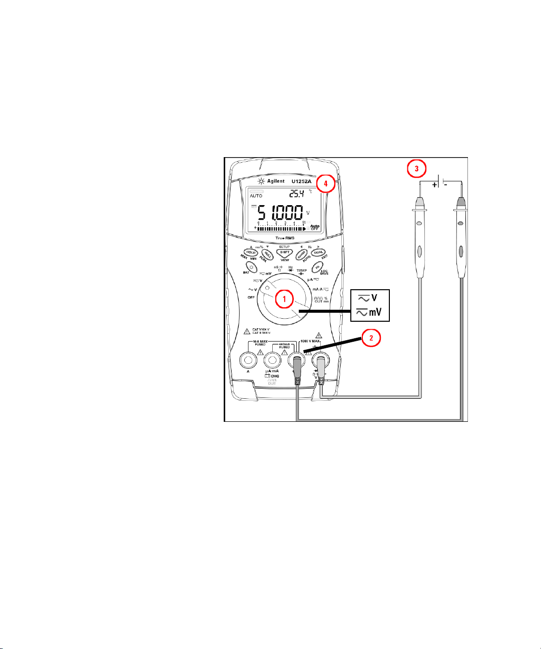
Measuring AC voltage
Red Lead
Black Lead
NOTE
Set up the multimeter to measure AC voltage as shown in
Figure 2- 1. Probe the test points and read the display.
Making Measurements 2
Figure 2-1 Measuring AC voltage
Press to display frequency on secondary display. See Ta b l e 1 - 8 of
“Selecting display with the Dual button” on page 18 for a list of the
different combinations available on the secondary display.
Agilent U1251A/U1252A User’s and Service Guide 25
Page 46
2 Making Measurements
Red Lead
Black Lead
Measuring DC voltage
Set up the multimeter to measure DC voltage as shown in
Figure 2- 2. Probe the test points and read the display.
MAX
Figure 2-2 Measuring DC voltage
26 Agilent U1251A/U1252A User’s and Service Guide
Page 47
Measuring Current
NOTE
µA & mA measurement
Making Measurements 2
Set up the multimeter to measure μA & mA as shown in
Figure 2- 3. Probe the test points and read the display.
• Press if necessary to ensure is shown on the display.
• For μA measurement, set the rotary switch to and connect
the positive test lead to μA.mA.
• For mA measurement, set the rotary switch to and
connect the positive test lead to μA.mA.
• For A (ampere) measurement, set the rotary switch to and
connect the positive test lead to A.
• Press to display dual measurements. See Ta b l e 1 - 8 of “Selecting
display with the Dual button” on page 18 for a list of dual
measurements available. Press and hold for more than 1 second
to exit dual display mode.
Agilent U1251A/U1252A User’s and Service Guide 27
Page 48

2 Making Measurements
Red Lead
Black Lead
Figure 2-3 Measuring μA and mA current
28 Agilent U1251A/U1252A User’s and Service Guide
Page 49

Percentage scale of 4 mA to 20 mA
NOTE
Set up the multimeter to measure percentage scale as shown
in Figure 2- 4. Probe the test points and read the display.
• Press to select percentage scale display. Ensure that or
is shown on the display.
• The percentage scale for 4 mA to 20 mA or 0 mA to 20 mA is calculated
using its corresponding DC mA measurement. The U1251A/U1252A
will automatically optimize the best resolution according to Ta b l e 2 - 2
below.
• Press to change the measurement range.
The percentage scale for 4 mA to 20 mA or 0 mA to 20 mA
is set to two ranges as follows:
Tab l e 2 - 2 Percentage scale and measurement range
Making Measurements 2
Percentage scale (4 mA to 20 or 0 mA to 20 mA)
Always auto range
999.99%
9999.9%
Agilent U1251A/U1252A User’s and Service Guide 29
DC mA auto or manual
range
50 mA, 500 mA
Page 50

2 Making Measurements
Red Lead
Black Lead
Figure 2-4 Measuring scale of 4-20 mA
30 Agilent U1251A/U1252A User’s and Service Guide
Page 51

A (ampere) measurement
NOTE
Red Lead
Black Lead
Set up the multimeter to measure A (ampere) as shown in
Figure 2- 5. Probe the test points and read the display.
Making Measurements 2
Connect the red and black test leads to the 10 A input terminal A and COM
respectively. The meter is set to A measurement automatically when the
red test lead is plugged into the A terminal.
Figure 2-5 A (ampere) current measurement
Agilent U1251A/U1252A User’s and Service Guide 31
Page 52

2 Making Measurements
WARNING
NOTE
Frequency Counter
• Use the frequency counter for low voltage applications only. Never use
the frequency counter for line power system.
• For inputs more than 30 Vpp, you are required to use frequency
measurement mode available under the current or voltage
measurement instead of frequency counter.
Set up the multimeter to measure frequency as shown in
Figure 2- 6. Probe the test points and read the display.
• Press to select the Frequency counter (Hz) function. “-1-“ on
the secondary display means the input signal frequency is divided by 1.
This allows signals of up to a maximum frequency of 985 kHz to be
measured.
• If the reading is unstable or is zero, press to select the division
of the input signal frequency by 100. This allows for a higher frequency
range of up to 20 MHz to be measured.
32 Agilent U1251A/U1252A User’s and Service Guide
• The signal is out of range if the reading is still unstable after the above
step.
• While the secondary display shows “-1-“, you may scroll through the
pulse width (ms), duty cycle (%), and frequency (Hz) measurements by
pressing .
Page 53

Making Measurements 2
Hz
Red Lead
Black Lead
Figure 2-6 Measuring frequency
Agilent U1251A/U1252A User’s and Service Guide 33
Page 54

2 Making Measurements
CAUTION
Red Lead
Black Lead
nS
Ω
Measuring Resistance, Conductance and Testing Continuity
Disconnect the circuit power and discharge all high-voltage capacitors
before measuring the resistance to prevent any possible damage to the
multimeter or the device under test.
Set up the multimeter to measure resistance as shown in
Figure 2- 7. Then probe the test points (by shunting the
resistor) and read the display.
34 Agilent U1251A/U1252A User’s and Service Guide
Figure 2-7 Measuring resistance
Page 55

Audible
continuity
Making Measurements 2
Press to scroll through audible continuity, conductance
and resistance tests as shown in Table 2- 8.
Press
SHIFT
MAX
Press
SHIFT
Figure 2-8 Audible continuity, conductance, and resistance test.
Agilent U1251A/U1252A User’s and Service Guide 35
Press
Page 56

2 Making Measurements
Audible continuity
In the range of 0–500 Ω, the beeper will sound if the
resistance value falls below 10 Ω. For other ranges, the
beeper will sound if the resistance falls below the typical
values indicated in Table 2- 3 below.
Tab l e 2 - 3 Audible continuity measurement range
Measurement range Beeper sound threshold
500.00 Ω < 10 Ω
5.0000 kΩ < 100 Ω
50.000 kΩ < 1 kΩ
500.00 kΩ < 10 kΩ
5.0000 MΩ < 100 kΩ
50.000 MΩ < 1 MΩ
500.00 MΩ < 10 MΩ
Conductance
Set up the multimeter to measure conductance as shown in
Figure 2- 9. Probe the test points and read the display.
The conductance measurement enables the measurement of
very high resistance of up to 100 GΩ.
As the high- resistance readings are susceptible to noise, you
can capture the average readings by using the Dynamic
Recording mode. Refer to the section “Dynamic
Recording” on page 50 for more information.
36 Agilent U1251A/U1252A User’s and Service Guide
Page 57

Making Measurements 2
Ω
nS
Red Lead
Black Lead
MAX
Figure 2-9 Conductance measurement
Agilent U1251A/U1252A User’s and Service Guide 37
Page 58

2 Making Measurements
CAUTION
NOTE
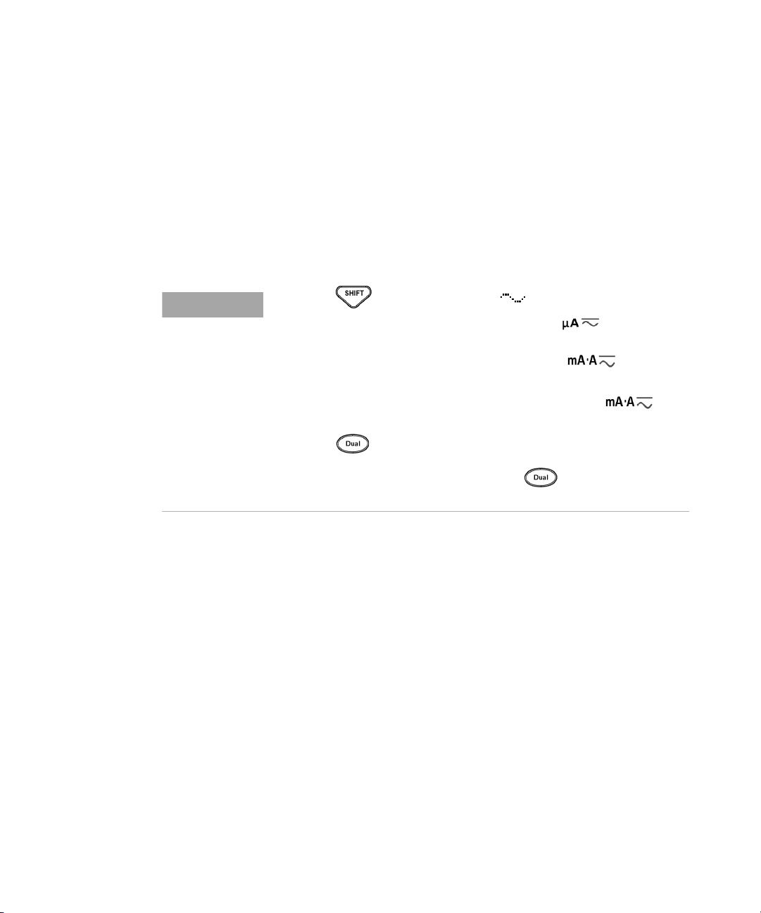
Testin g D iodes
Disconnect the circuit power and discharge all the high-voltage capacitors
before testing the diodes to prevent any possible damage to the meter.
To test a diode, turn the power off to the circuit and remove
the diode from the circuit. Set up the multimeter as shown
in Figure 2- 10, then use the red probe lead on the positive
terminal (anode) and use the black probe lead on the
negative terminal (cathode) and read the display.
• The cathode is the side with band(s).
•
The meter can display the diode’s forward bias of up to approximately
2.1 V. A typical diode’s forward bias is between the range of 0.3 V to
0.8 V.
38 Agilent U1251A/U1252A User’s and Service Guide
Next, reverse the probes and measure the voltage across the
diodes again as shown in Figure 2- 11 on page 40. The
diode’s test result is based on the following:
• The diode is considered good if the meter displays “OL”
in reverse bias mode.
• The diode is considered shorted if the meter displays
approximately 0 V in both forward and reverse bias
modes, and the meter beeps continuously.
• The diode is considered open if the meter displays “OL”
in both forward and reverse bias modes.
Page 59
Making Measurements 2
Red Lead
Black Lead
Hz
Figure 2-10 Measuring forward bias of diode
Agilent U1251A/U1252A User’s and Service Guide 39
Page 60

2 Making Measurements
Red Lead
Black Lead
Hz
Figure 2-11 Measuring reverse bias of diode
40 Agilent U1251A/U1252A User’s and Service Guide
Page 61

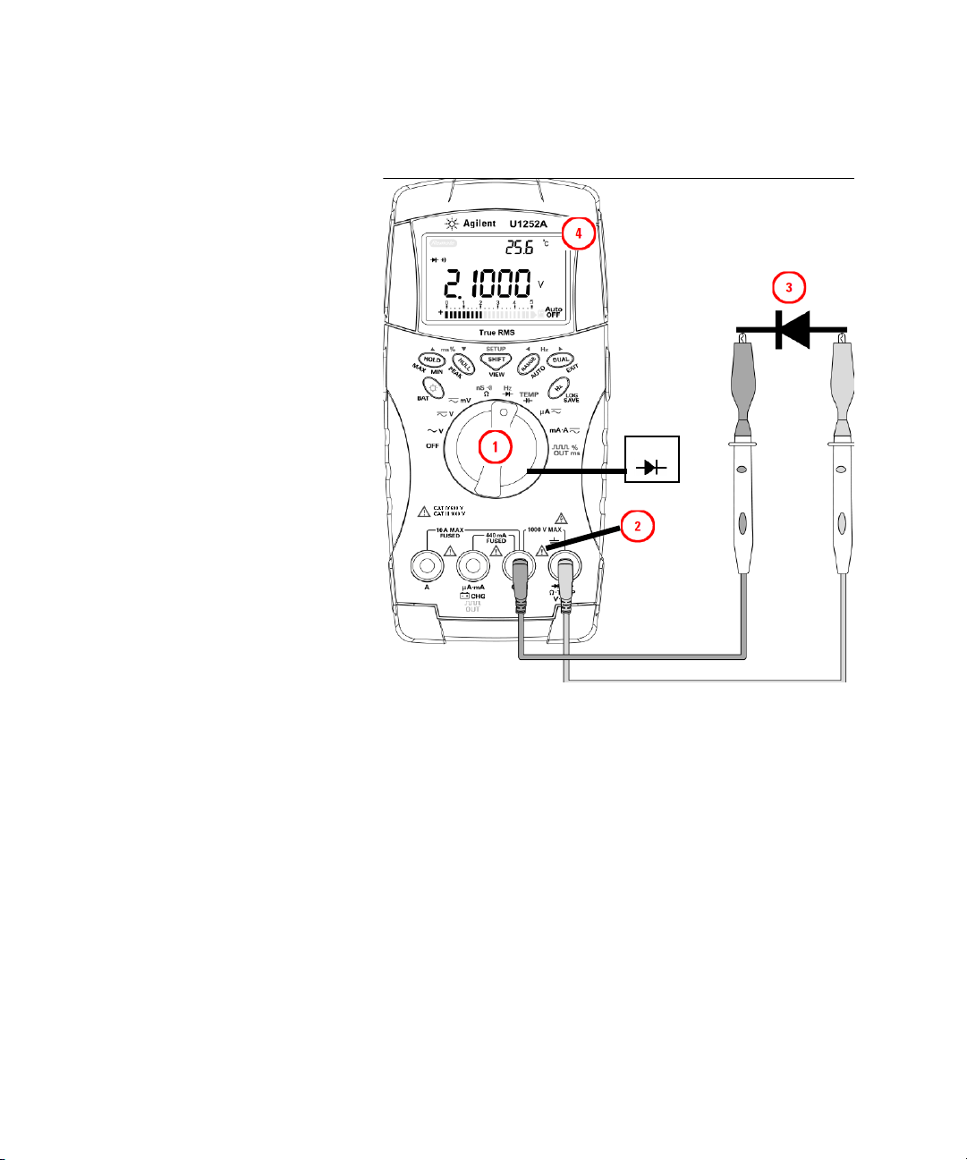
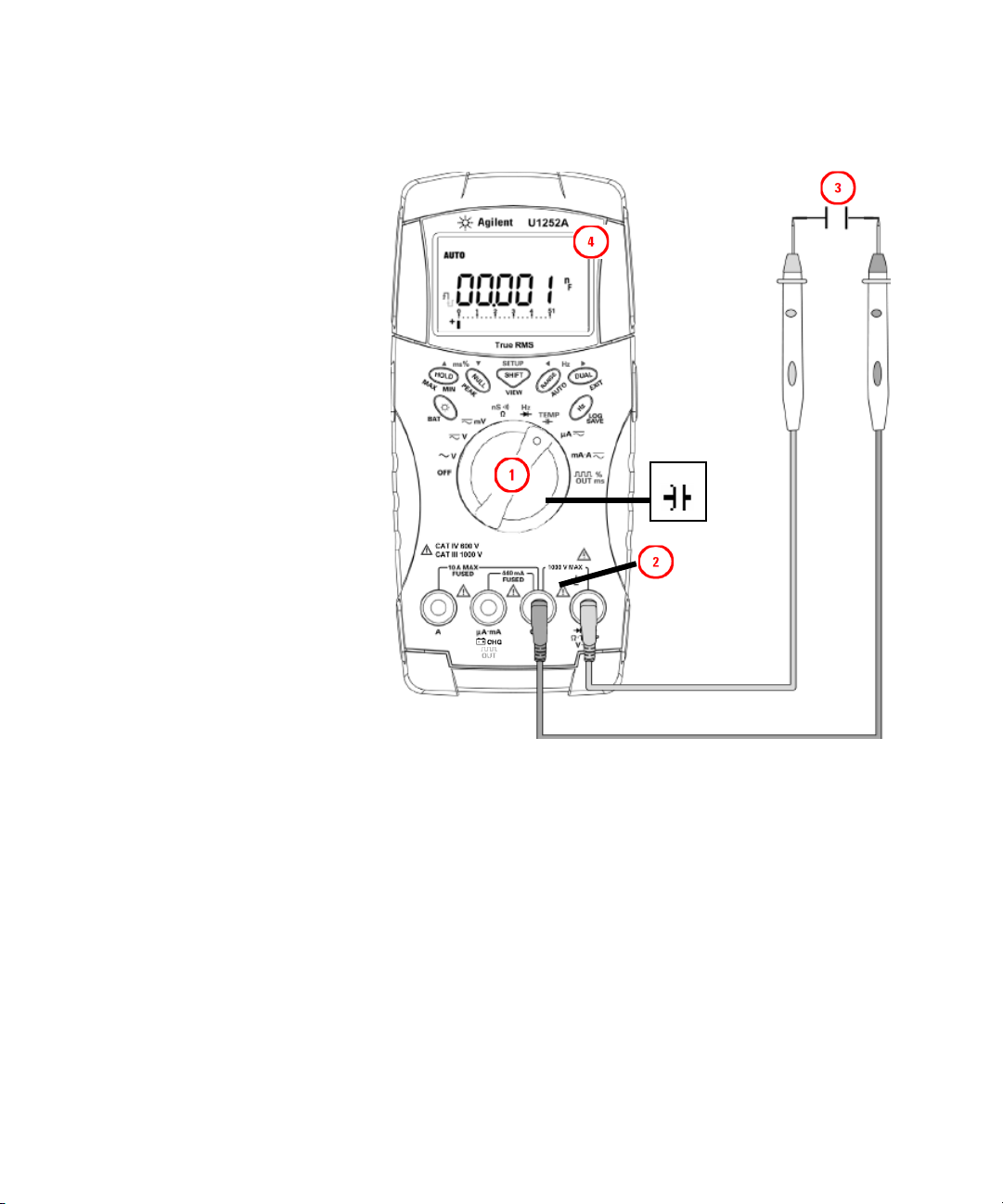
Measuring Capacitance
CAUTION
NOTE
Disconnect the circuit power and discharge all the high-voltage capacitors
before measuring the capacitance to prevent any possible damage to the
meter or the device under test. To confirm that the capacitors have
discharged, use the DC voltage function.
The meter measures capacitance by charging the capacitor
with a known current for a period of time, measuring the
voltage and then calculating the capacitance. The larger the
capacitor, the longer the charge time. Below are some tips
for measuring capacitance:
Making Measurements 2
• For measuring capacitance greater than 10,000 µF,
discharge the capacitor first, then select a suitable
range for the measurement. This will speed up
measuring time in order to obtain the correct
capacitance value.
• For measuring smaller capacitance ranges, press
with the test leads open to subtract any residual
capacitance from the meter or the leads.
Agilent U1251A/U1252A User’s and Service Guide 41
means the capacitor is charging. means the capacitor is
discharging.
Set up the multimeter as shown in Figure 2- 12. Use the red
probe lead on the positive terminal of the capacitor and the
black probe lead on the negative terminal and read the
display.
Page 62
2 Making Measurements
Red Lead
Black Lead
TEMP
Figure 2-12 Capacitance measurements
42 Agilent U1251A/U1252A User’s and Service Guide
Page 63

Measuring Temperature
CAUTION
Do not bend the thermocouple leads at sharp angles. Repeated bending
over a period of time may break the leads.
The bead type thermocouple probe is suitable for making
temperature measurements between –20 °C to 200 °C in
PTFE compatible environments.
Do not use the bead- type thermocouple probe beyond the
recommended operating temperature range. Do not immerse
this thermocouple probe in liquids. For best results, use a
thermocouple probe designed for each application — an
immersion probe for liquid or gel and an air probe for air
measurements.
Set up the multimeter to measure temperature as shown in
Figure 2- 15 or observe the following steps:
1 Press to select the temperature measurement.
2 Connect the miniture thermal probe into the
3 Connect the thermal probe with the adapter into the
4 For best performance, place the meter in the operating
5 Clean the measurement surface and make sure the probe
6 When measuring above the ambient temperature, move the
7 When measuring below ambient temperature, move the
Making Measurements 2
non- compensation transfer adaptor as shown in
Figure 2- 13.
meter input terminals as shown in Figure 2- 14.
environment for at least one hour to stabilize the unit to
environment temperatures.
is securely touching the surface. Remember to disable the
applied power.
thermocouple along the surface until you get the highest
temperature reading.
thermocouple along the surface until you get the lowest
temperature reading.
Agilent U1251A/U1252A User’s and Service Guide 43
Page 64

2 Making Measurements
8 For a quick measurement, use the 0 °C compensation
adapter to see the temperature variation of the
thermocouple sensor. The 0 °C compensation adapter
assists in measuring the relative temperature immediately.
Figure 2-13 Connecting the thermal probe into the non-compensation
transfer adapter
Figure 2-14 Connecting the probe with adapter into the multimeter
44 Agilent U1251A/U1252A User’s and Service Guide
Page 65

Making Measurements 2
If you are working in a constantly varying environment,
where ambient temperatures are not constant, do the
following:
1 Press to select 0 °C compensation. This gives a
quick measurement of the relative temperature.
2 Avoid contact between the thermocouple probe and the
measurement surface.
3 After a constant reading is obtained, press to set
the reading as the relative reference temperature.
4 Touch the measurement surface with the thermocouple
probe.
5 Read the display for the relative temperature.
Agilent U1251A/U1252A User’s and Service Guide 45
Page 66

2 Making Measurements
TEMP
Figure 2-15 Surface temperature measurement
46 Agilent U1251A/U1252A User’s and Service Guide
Page 67

Alerts and Warning During Measurement
WARNING
Overload alert
For your safety, look out for this alert. When you are alerted,
immediately remove the test leads from the measuring source.
The meter provides an overload alert for voltage
measurements in both auto and manual range modes. The
meter beeps periodically once the measuring voltage exceeds
1010 V. For your safety, please be aware of this alert.
Input warning
The meter sounds an alert beep when the test lead is
inserted into the A input terminal but the rotary switch is
not set to the corresponding mA.A location. The primary
display indicates a flashing “A- Err” until the test lead is
removed from the A input terminal. Refer to Figure 2- 16.
Making Measurements 2
Agilent U1251A/U1252A User’s and Service Guide 47
Figure 2-16 Input terminal warning
Page 68

2 Making Measurements
Charge terminal alert
The meter sounds an alert beep when the terminal
detects a voltage level of more than 5 V and the rotary
switch is not set to the corresponding location. The
primary display indicates a flashing “Ch.Err” until the lead
is removed from the input terminal.
Refer to Figure 2- 17 below.
Figure 2-17 Charge terminal alert
48 Agilent U1251A/U1252A User’s and Service Guide
Page 69

Agilent U1251A and U1252A Handheld Digital Multimeter
User’s and Service Guide
3
Functions and Features
Dynamic Recording 50
Data Hold (Trigger Hold) 52
Refresh Hold 53
Null (Relative) 55
Decibel Display 57
1 ms Peak Hold 59
Data Logging 61
Manual logging 61
Interval logging 63
Reviewing logged data 65
Square Wave Output (for U1252A) 67
Remote Communication 71
This chapter contains information on the functions and
features that are available for the U1251A and U1252A
digital multimeter.
Agilent Technologies
49
Page 70
3 Features and Functions
NOTE
Dynamic Recording
The Dynamic Recording mode can be used to detect
intermittent turn- on or turn- off voltage, current surges or to
verify measurement performance without you being present
during the process. While the readings are being recorded,
you are free to perform other tasks.
The average reading is useful for smoothing out unstable
inputs, estimating the percentage of time a circuit is
operating and verifying circuit performance. The elapsed
time is shown on the secondary display. The maximum time
is 99999 seconds. When this maximum time is exceeded, “OL”
is shown on the display.
1 Press for more than 1 second to enter Dynamic
Recording mode. The meter is now in continuous mode or
non- data hold (non- trigger) mode. “MAXMINAVG” and
the present value of measurement are displayed. The
multimeter will beep when a new maximum or minimum
value is recorded.
2 Press to cycle through maximum, minimum,
average, and present readings. The MAX, MIN, AVG , and
MAXMINAVG indicators will appear, corresponding to the
displayed readings.
3 Press or for more than 1 second to exit
Dynamic Recording mode.
• Press to restart the dynamic recording.
• The average value is the true average of all the measured values taken
in the Dynamic Recording mode. If an overload is recorded, the
averaging function will stop and the average value becomes
"OL"(overload). is disabled in Dynamic Recording mode.
50 Agilent U1251A/U1252A User’s and Service Guide
Page 71

Features and Functions 3
Press Max Min for > 1 sec
or press for > 1 sec
Press Max Min for > 1 sec
or press for > 1 sec
Press Max Min for > 1 sec
or press for > 1 sec
Press Max Min
for > 1 sec
Press Max Min
Press Max Min
Press Max Min
Figure 3-1 Dynamic recording mode operation
Agilent U1251A/U1252A User’s and Service Guide 51
Page 72

3 Features and Functions
Press
Press
Press
Data Hold (Trigger Hold)
The data hold function allows the user to freeze the
displayed digital value.
1 Press to freeze the displayed value and to enter the
2 Press again to freeze the next value being
3 Press and hold or for more than 1 second to
manual trigger mode. TRIG is displayed.
measured. TRIG flashes before the new value is updated
on the display.
quit the data hold function.
Figure 3-2 Data hold mode operation
52 Agilent U1251A/U1252A User’s and Service Guide
Page 73

Refresh Hold
Features and Functions 3
The Refresh Hold function allows you to freeze the displayed
value. The bar- graph is not held and will continue to reflect
the instantaneous measured value. You can use the Setup
mode to enable Refresh Hold mode when you are working
with fluctuating values. This function will auto trigger or
update the held value with a new measured value and emit
a tone as a reminder.
1 Press to enter Refresh Hold mode. The present
value will be held and the symbol will appear.
2 It will be ready to hold a new measured value once the
variation of measured values exceeds the variation count
setting. While the multimeter is waiting for a new stable
value, the symbol will flash.
3 The symbol will stop f lashing once the new
measured value is stable and the new value will be
updated to the display. The symbol will remain on and
the multimeter will emit a tone to remind you of this.
4 Press again to quit the Refresh Hold function.
Agilent U1251A/U1252A User’s and Service Guide 53
Page 74

3 Features and Functions
The HOLD sign flashes
until the measured
value is stable and
updated
Press
Variation counts
> setting
Measurement
is updated
Press to return
NOTE
54 Agilent U1251A/U1252A User’s and Service Guide
Figure 3-3 Refresh hold mode operation
• For voltage and current measurements, the holding value will not be
updated if the reading is below 500 counts.
• For resistance and diode measurements, the holding value will not be
updated if the reading is in “OL” (open state).
• The holding value may not be updated when the reading does not reach
a stable state for all measurements.
Page 75

Null (Relative)
NOTE
Features and Functions 3
The Null function subtracts a stored value from the present
measurement and displays the difference between the two.
1 Press to store the displayed reading as the
reference value to be subtracted from subsequent
measurements and to set the display to zero. NULL is
displayed.
2 Press to see the stored reference value. NULL
flashes for 3 seconds before the display returns to zero.
3 To exit this mode, press while NULL is flashing on
the display.
• Null can be set for both auto and manual range settings, but not in the
event of an overload.
• When taking a resistance measurement and the meter reads a
non-zero value due to the presence of test leads, use the Null function
to adjust the display to zero.
• When taking a DC voltage measurement, the thermal effect will
influence the accuracy. Short the test leads and press Null once the
displayed value is stable in order to zero out the display.
Agilent U1251A/U1252A User’s and Service Guide 55
Page 76

3 Features and Functions
Press
Press
Press
Figure 3-4 Null (relative) mode operation
56 Agilent U1251A/U1252A User’s and Service Guide
Page 77

Decibel Display
NOTE
Features and Functions 3
The dBm operation calculates the power delivered to a
reference resistance relative to 1 mW and can be applied to
DC V, AC V, and AC + DC V measurements for decibel
conversion. The voltage measurement is converted to dBm by
using the following formula:
The reference resistance may be selected from 1~9999 Ω in
Setup mode. The default value is 50 Ω.
The decibel of voltage is calculated with respect to 1 V. The
equation for the voltage measurement is as follows:
dBV = 20 log
1 At the , , or rotary switch position,
press to scroll to the dBm measurement on the
primary display. The secondary display indicates the AC
voltage measurement.
If the rotary switch is at the “~ V” position, press to switch
between the dBV and the dBm measurements. The dBm or the dBV
measurements can be selected at the ACV position. The selection will be
the reference for other voltage measurements.
2 Press for more than 1 second to exit this mode.
10
Vin
Agilent U1251A/U1252A User’s and Service Guide 57
Page 78

3 Features and Functions
Press
Press
Press
Press
Press
Press
Press
Press
Press
Press
58 Agilent U1251A/U1252A User’s and Service Guide
Figure 3-5 dBm/dBV display mode operation
Page 79

1 ms Peak Hold
NOTE
Features and Functions 3
The Peak Hold function allows the measurement of peak
voltage for analysis of components such as power
distribution transformers and power factor correction
capacitors. The peak voltage obtained can be used to deter-
mine the crest factor:
Crest factor = Peak value/True RMS value
1 Press for more than 1 second to toggle 1 ms Peak
Hold mode ON / OFF.
2 Press to scroll through maximum and minimum
peak readings. MAX indicates the maximum peak,
while MIN indicates the minimum peak.
• If the reading is "OL", press to change the measuring range and
to re-start the peak-recording measurement.
• If you need to re-start the peak recording, press .
3 Press and hold or for more than 1 second
to exit this mode.
4 According to the measurements shown in Figure 3- 6 on
page 60, the crest Factor will be 2.5048/1.768 =1.416.
Agilent U1251A/U1252A User’s and Service Guide 59
Page 80

3 Features and Functions
Press
Press
Press
Press
Press
Press
Figure 3-6 1 ms peak hold mode operation
60 Agilent U1251A/U1252A User’s and Service Guide
Page 81

Data Logging
NOTE
Features and Functions 3
The data logging function provides the convenience of
recording test data for future review or analysis. Since data
is stored in nonvolatile memory, the data remains saved
even if the multimeter is turned OFF or the battery is
changed.
The two options offered are manual (hand) logging and
interval (time) logging functions, which is determined in the
Setup mode.
Data logging records the values on the primary display only.
To use the data logging function, you will need to connect the multimeter
to a PC using the U1173A IR-to-USB cable (purchased separately) and
download the data logging software from Agilent’s website. Please go to:
http://www.agilent.com/find/hhTechLib to download the software.
Manual logging
Firstly, ensure that manual (hand) logging is specified in
Setup mode.
1 Press for more than 1 second to store the present
value and function on the primary display to the
non- volatile memory. The and the logging index
will be indicated. The logging index flashes on the
secondary display for 3 seconds before returning to
normal display.
2 Press and hold again for the next value that you
would like to save into the memory.
Agilent U1251A/U1252A User’s and Service Guide 61
Page 82

3 Features and Functions
Press
Press
NOTE
Press
Figure 3-7 Hand (Manual) logging mode operation
The maximum data that can be stored is 100 entries. When the 100 entries
are filled, the secondary display indicates “FULL”, as shown in Figure 3-8.
Figure 3-8 Full Log
62 Agilent U1251A/U1252A User’s and Service Guide
Page 83

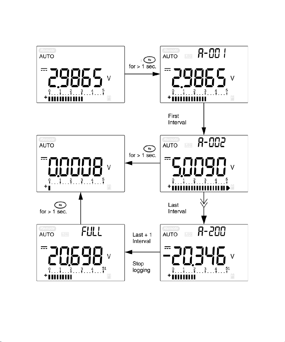
Interval logging
NOTE
NOTE
Firstly, ensure that interval (time) logging is specified in
Setup mode.
1 Press for more than 1 second to store the present
The maximum data that can be stored is 200 entries. When the 200 entries
are filled, “FULL” is indicated on the secondary display.
2 Press for more than 1 second to exit this mode.
When interval (automatic) logging is enabled, all keypad operations are
disabled, except for the Log function.
Features and Functions 3
value and function on the primary display into the
non- volatile memory. The and the logging index will
be indicated. The readings are automatically saved into
the permanent memory at intervals set using the Setup
mode.
Agilent U1251A/U1252A User’s and Service Guide 63
Page 84
3 Features and Functions
Press
Press
Press
Figure 3-9 Interval (Automatic) logging mode operation
64 Agilent U1251A/U1252A User’s and Service Guide
Page 85

Reviewing logged data
1 Press for more than 1 second to enter the Log
Review mode. The last recorded entry and the last logging
index are displayed.
2 Press to switch between hand (manual) and interval
(automatic) logging review mode.
3 Press to ascend or to descend through the logged
data. Press to select the first record and press to
select the last record for quick navigation.
4 Press for more than 1 second at the respective Log
Review mode to clear logged data.
5 Press for more than 1 second to exit mode.
6 During the data review in either manual or interval
logging mode, press for more than one second to
clear all the logged values.
Features and Functions 3
Agilent U1251A/U1252A User’s and Service Guide 65
Page 86

3 Features and Functions
Press
Press
Press
Press
Press
Press
Press
Press
Press
Press
Press
Press
Press
Press
Press
Press
Press Press
Press
Figure 3-10 Log review mode operation
66 Agilent U1251A/U1252A User’s and Service Guide
Page 87

Square Wave Output (for U1252A)
NOTE
The square wave output function can be used to generate a
Press
0.5, 1, 2, 5, 10, 15, 20, 25, 30, 40, 50, 60, 75, 80, 100, 120, 150, 200, 240, 300, 400, 480, 600, 800, 1200, 1600,
2400, 4800
PWM (pulse width modulation) output or provide a synchro-
nous clock source (baud rate generator). You can also use
this function to check and calibrate flow- meter displays,
counters, tachometers, oscilloscopes, frequency converters,
frequency transmitters, and other frequency input devices.
1 Turn the rotary switch to position. The default
display setting is 600 Hz on the secondary display and
50% duty cycle on the primary display.
2 Press or to scroll through the available frequencies
(choose from the available 28 frequencies):
Frequency (Hz)
Features and Functions 3
Pressing is the same as pressing .
3 Press to select the duty cycle (%) on the primary
display.
4 Press or to adjust the duty cycle. Duty cycle can
be set for 256 steps and each step is 0.390625%. The
display only indicates the best resolution with 0.001%.
Agilent U1251A/U1252A User’s and Service Guide 67
Page 88

3 Features and Functions
Figure 3-11 Frequency adjustment for square wave output
5 Press to select the pulse width (ms) on the primary
display.
6 Press or to adjust the pulse width. The pulse
width can be set for 256 steps and each step is 1/ (256 x
Frequency). The display range automatically adjusts in the
range of 9.9999~9999.9 ms.
68 Agilent U1251A/U1252A User’s and Service Guide
Page 89

Press
Press
Press
Press
Press
Press
Press
Press
Features and Functions 3
Agilent U1251A/U1252A User’s and Service Guide 69
Figure 3-12 Pulse width adjustment for square wave output
Page 90

3 Features and Functions
Figure 3-13 Duty cycle adjustment for Square Wave
70 Agilent U1251A/U1252A User’s and Service Guide
Page 91

Remote Communication
to PC
Connect
The meter has a bi- directional (full duplex) communication
capability that speeds data storing from the meter to the PC.
To use this feature, you are required to use the optional
IR- USB cable with the application software included in the
CD or downloadable from the Agilent Web site.
For details on performing PC to meter remote
communication click on Help after launching the Agilent GUI
Data Logger Software or refer to the GUI Data Logger Quick
Start Guide (U1251- 90023) for more information.
Features and Functions 3
Figure 3-14 Cable connection for remote communication
Agilent U1251A/U1252A User’s and Service Guide 71
Page 92

3 Features and Functions
72 Agilent U1251A/U1252A User’s and Service Guide
Page 93

Agilent U1251A and U1252A Handheld Digital Multimeter
User’s and Service Guide
4
Changing The Default Setting
Selecting Setup Mode 74
Setting Data Logging Mode 78
Setting Thermocouple Types (U1252A only) 79
Setting Reference Impedance for dBm Measurement 80
Setting Minimum Frequency Measurement 81
Setting Temperature Unit 82
Setting Auto Power Saving Mode 84
Setting Percentage (%) Scale Readout 86
Setting Beep Frequency 87
Setting Backlight Timer 88
Setting Baud Rate 89
Setting Parity Check 90
Setting Data Bit 91
Setting Echo Mode 92
Setting Print Mode 93
Returning to Default Factory Settings 94
This chapter shows you how to change the default factory
settings of the U1251A and U1252A and other available
setting options
Agilent Technologies
73
Page 94

4 Changing The Default Setting
NOTE
Selecting Setup Mode
To enter the Setup mode, perform the following steps:
1 Turn the meter OFF.
2 From the OFF position, press and hold while
turning the rotary switch to any non- OFF position.
When you hear a beep, the meter is in Setup mode and you can release
To change a menu item setting in Setup mode, perform the
following steps:
1 Press or to scroll through the menu items.
2 Press or to scroll through the available settings.
See Table 4- 1, “Available setting options in Setup mode,”
for details of available options.
3 Press to save changes. These parameters will remain
in the non- volatile memory.
4 Press for more than 1 second to exit Setup mode.
74 Agilent U1251A/U1252A User’s and Service Guide
Page 95

Table 4-1 Available setting options in Setup mode
Menu Item Available setting options Default factory
Display Description Display Description
OFF Enables Data Hold (manual trigger)
100–1000
Sets the variation count that determines Refresh
Hold (auto trigger)
Enables the reset of factory settings by pressing
dEFAU
and holding for more than 1 second
rHoLd
rESEt
[1]
Refresh Hold
Reset
Changing The Default Setting 4
setting
500
dEFAU
Print
ECHO
dAtAb
PAr tY
bAUd
b-Lit
bEEP
PErnt
APF
FrEq
rEF
Print
Echo
Data bits
Parity check
Baud rate
Backlit display
Frequency of beep
sound of meter
Percentage scale
Auto power off
Minimum frequency
that can be measured
Reference impedance
for dBm measurement
ON, OFF
ON, OFF
7-bit, 8-bit
En, Odd, nOnE
2400 Hz, 4800
Hz, 9600 Hz,
19200 Hz
1–99 s
Enables auto send of data to the PC continuously
when set to ON
Enables the return of characters to the PC when
set to ON
Sets the data bit length for the remote
communication (remote control with PC)
Sets the even, odd or no parity check for the
remote communication (remote control with PC)
Sets the baud rate for the remote communication
(remote control with PC)
Sets the timer for the auto turn-off for the backlit
[2]
display
OFF Disables the auto turn-off for the backlit display
2400 Hz, 1200
Hz, 600 Hz,
Sets the frequency of the meter’s beep sound
300 Hz
OFF Disables the meter’s beep sound
0–20 mA, 4–20
mA
[2]
1–99 m
Sets the % scale readout 4–20 mA
Sets the timer for auto power off
OFF Disables auto power off
0.5 Hz, 1 Hz, 2
Hz, 5 Hz
[2]
1–9999 Ω
Sets the minimum frequency that can be
measured
Sets the reference impedance for dBm
measurement
OFF
OFF
8-bit
nOnE
9600 Hz
30 s
2400 Hz
10 m
0.5 Hz
50 Ω
Agilent U1251A/U1252A User’s and Service Guide 75
Page 96

4 Changing The Default Setting
Table 4-1 Available setting options in Setup mode (continued)
t.CoUP
[3]
Thermocouple
tYPE K Sets the thermocouple type to K-type
tYPE J Sets the thermocouple type to J-type
Hand Enables manual data logging
d-LoG
Data logging
1–9999 s
[2]
Sets the interval for automatic data logging
Sets the temperature measurement to °C but
d-CF
pressing swaps the display to °F
d-F Sets the temperature measurement to °F
[4]
tEMP
Te m p e r a t u r e
d-FC
Sets the temperature measurement to °F but
pressing
swaps display to °C
d-C Sets the temperature measurement to °C
Notes for setting options in Setup mode:
1 This is the first option displayed once the user enters Setup mode.
2 For b-Lit, APF, rEF and d-LoG menu items, the user can select the digit to be adjusted by pressing
3 This menu option is only available for the U1252A.
4 To view the tEMP menu item, press
for more than 1 second.
tYPE K
Hand
d-CF
76 Agilent U1251A/U1252A User’s and Service Guide
Page 97

Setting Data Hold/Refresh Hold Mode
1. Set OFF to enable the Data Hold mode (manual trigger by
key or bus via the remote control).
2. Set the variation count within the 100 to 1000 range to
enable the Refresh Hold mode (auto trigger). When the
variation of the measuring value exceeds the setting of the
variation count the Refresh Hold will be ready to trigger.
Press
Changing The Default Setting 4
Press
Press
Press
Press
Figure 4-1 Data hold/Refersh hold setup
Agilent U1251A/U1252A User’s and Service Guide 77
Page 98

4 Changing The Default Setting
Setting Data Logging Mode
1 Set to “Hand” to enable the manual data logging mode.
2 Set the interval within 0001 to 9999 seconds to enable
interval (automatic) data logging mode.
3 Press and hold or for more than 1 second to switch
between manual and interval data logging setup.
Press
Press
Press
Press
Press
Figure 4-2 Data logging setup
78 Agilent U1251A/U1252A User’s and Service Guide
Press
Page 99

Setting Thermocouple Types (U1252A only)
Press
The thermocouple sensor types that can be selected are
type- K (default) or type- J. Press or to switch
between the J and the K type.
Changing The Default Setting 4
Figure 4-3 Thermocouple type setup
Agilent U1251A/U1252A User’s and Service Guide 79
Page 100

4 Changing The Default Setting
Setting Reference Impedance for dBm Measurement
The reference impedance can be set from 1 to 9999 W. The
default value is 50 W.
Press
Press
Press
Press
Figure 4-4 Reference impedance for dBm measurement setup
80 Agilent U1251A/U1252A User’s and Service Guide
 Loading...