

Page 1

NOTE
Agilent
U1231A/U1232A/U1233A
Handheld Multimeter
Quick Start Guide
Verify that you received the following items in the shipment of
your multimeter:
✔ One pair of red and black test leads
✔ Four 1.5 V AAA alkaline battery
✔ Printed copy of the U1231A/U1232A/U1233A
Quick Start Guide
If any item is missing or damaged, keep the shipping materials
and contact the nearest Agilent Sales Office.
The descriptions and instructions in this guide apply to the
U1231A, U1232A, and U1233A handheld multimeters.
The model U1233A appears in all illustrations.
All related documents and software are available for download
at www.agilent.com/find/hhTechLib.
Agilent Technologies
Page 2
U1231A/U1232A/U1233A Handheld Multimeter
To PC (host)
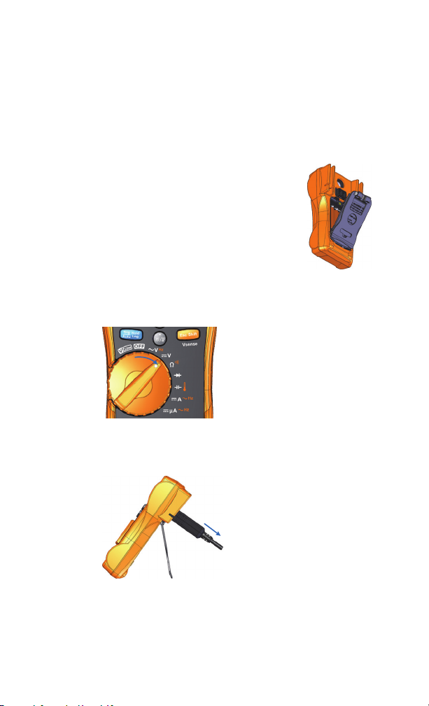
Install the Batteries
Install the Batteries
Your multimeter is powered by four 1.5 V AAA alkaline batteries (included with the shipment).
1 Turn the multimeter OFF and remove the test
leads from the terminals.
2 Loosen the screw on the battery cover with a
suitable Phillips screwdriver.
3 Remove the battery cover and observe the
polarity markings.
4 Insert the batteries and replace the battery
cover and screw.
Turn On the Multimeter
To power ON your multimeter,
turn the rotary switch to any
other position.
Controlling the Multimeter Remotely
Your multimeter is capable of
remote data logging.
To use this feature, you will
need a PC running a Windows
operating system, an IR-USB
cable (U1173A, purchased separately), and the Agilent GUI Data
Logger Software.
The Agilent GUI Data Logger software is downloadable for free
from www.agilent.com/find/hhTechLib.
2 U1231A/U1232A/U1233A Quick Start Guide
Page 3
U1231A/U1232A/U1233A Handheld Multimeter
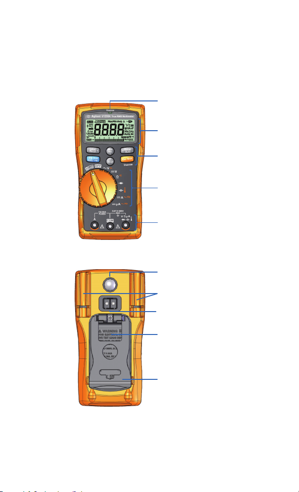
Vsense indicator
Keypad
Rotary switch
LED flashlight
Battery cover
Tilt stand
Display screen
Input terminals
Test lead/probe holders
IR communication port
(U1233A only)
The Multimeter at a Glance
The Multimeter at a Glance
U1231A/U1232A/U1233A Quick Start Guide 3
Page 4
U1231A/U1232A/U1233A Handheld Multimeter
NOTE
WARNING
S
h
i
f
t
E
s
c
Hz
AUX
Hz
Hz
AUX
Hz
AUX
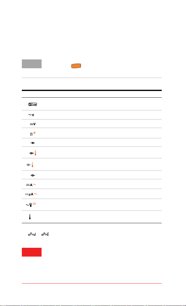
Understanding the Rotary Switch
Understanding the Rotary Switch
Some rotary switch positions have a shifted function printed in
orange. Press to switch between the shifted and regular
function.
Legend Functions shown in the primary display
Low input impedance — VZ
VZ
LOW
DC V/VZ
AC V for eliminating ghost voltages
LOW
AC V/Frequency
DC V
Resistance/Short continuity/Open continuity
Diode
Capacitance/Temperature (U1233A only)
Capacitance/Auxiliary Temperature (U1232A only)
Capacitance (U1231A only)
DC or AC A/Frequency
DC or AC μA/Frequency
Auto (AC or DC)/
LOW
[1]
Clamp-on AC or DC A/Frequency (U1231A only)
Auxiliary Temperature (U1231A only)
[1]
Open continuity option must be enabled through the multimeter’s Setup
( > ). Open continuity is disabled by default.
Remove the test leads from the measuring source or
target before changing the rotary switch position.
Refer to the U1231A/U1232A/U1233A User’s Guide for a
complete list and description of all rotary switch labels for
each separate multimeter model.
4 U1231A/U1232A/U1233A Quick Start Guide
Page 5
U1231A/U1232A/U1233A Handheld Multimeter
N
u
l
l
R
e
c
a
l
l
Max
Min
A
u
t
o
R
a
n
g
e
A
u
t
o
T
r
i
H
o
l
d
g
L
o
g
S
h
i
f
t
E
s
c
Hz
AUX
Hz
Hz
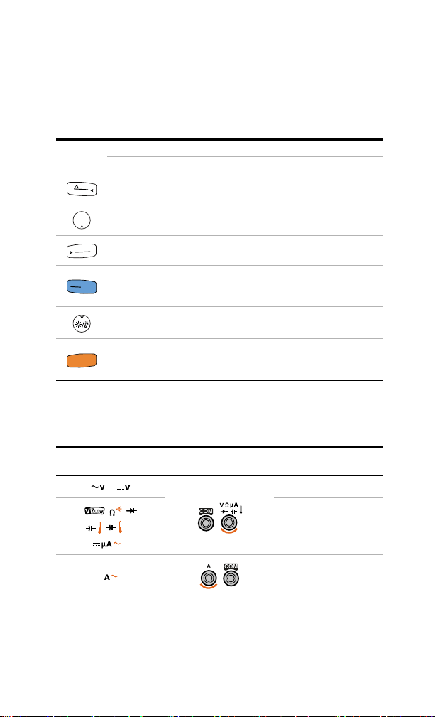
Understanding the Keypad
Understanding the Keypad
Legend
Sets the null/relative mode
Key response when pressed for:
Less than 1 second More than 1 second
Enters the Hold-Log Recall
menu
Starts the MaxMin recording Stops the MaxMin recording
Sets a manual range Enables autoranging
Freezes and stores the present
reading in the
display
Turns the LCD backlight on or
off.
Switches between the regular
and shifted (icons printed in
orange) functions
Automatically freezes the present reading
once the reading is stable
Turns the LED flashlight on or
off.
U1233A only: Enables the
non-contact voltage detector
(Vsense).
Understanding the Input Terminals
Rotary position for
U1232A and U1233A
Input terminals Overload protection
600 Vrms
600 Vrms for
short circuit <0.3 A
11 A/1000 V,
fast-acting fuse
U1231A/U1232A/U1233A Quick Start Guide 5
Page 6

U1231A/U1232A/U1233A Handheld Multimeter
WARNING
2
AC
Voltage source
S
h
i
f
t
E
s
c
1
> 1 s
3
NOTE
A
u
t
o
R
a
n
g
e
Understanding the Input Terminals
Non-contact voltage detector (Vsense)
Voltage could still be present even if there is no alert
indication. Do not rely on the Vsense detector with
shielded wire. Never touch live voltage or conductor
without the necessary insulation protection.
The Vsense detector may be affected by differences in
socket design, insulation thickness, and insulation type.
Press to change the Vsense detector’s sensitivity from
Hi.SE (high sensitivity) to Lo.SE (low sensitivity).
6 U1231A/U1232A/U1233A Quick Start Guide
Page 7

U1231A/U1232A/U1233A Handheld Multimeter
AC
4
1
3
Voltage source
2
Hz
2
DC
3
Voltage source
Performing Measurements
AC voltage measurements
DC voltage measurement
Performing Measurements
U1231A/U1232A/U1233A Quick Start Guide 7
Page 8

U1231A/U1232A/U1233A Handheld Multimeter
4
1
3
Resistor
2
S
h
i
f
t
E
s
c
2
ON
(closed)
OFF
(open)
3
Press again to switch
between testing for shorted ( ) or
open ( ) contacts.
S
h
i
f
t
E
s
c
Performing Measurements
Resistance measurement
Continuity test
8 U1231A/U1232A/U1233A Quick Start Guide
Page 9

Forward bias diode test
4
1
3
Forward bias diode
2
3
Reverse bias diode
4
Reverse bias diode test
U1231A/U1232A/U1233A Handheld Multimeter
Performing Measurements
U1231A/U1232A/U1233A Quick Start Guide 9
Page 10
U1231A/U1232A/U1233A Handheld Multimeter
CAUTIONCAUTION
4
1
3
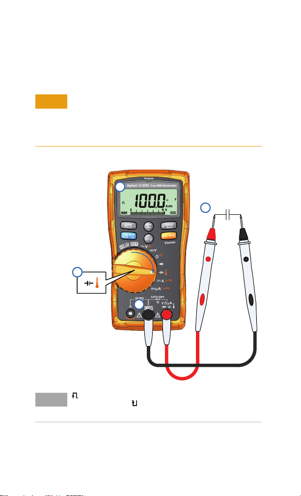
Capacitance
2
NOTE
Performing Measurements
Capacitance measurement
To avoid possible damage to the multimeter or to the equipment under test, disconnect circuit power and discharge all
high-voltage capacitors before measuring capacitance. Use
the DC V function to confirm that the capacitor is fully discharged.
is shown on the bottom left of the display when the capacitor is charging, and is shown when the capacitor is discharging.
10 U1231A/U1232A/U1233A Quick Start Guide
Page 11

U1231A/U1232A/U1233A Handheld Multimeter
WARNING
4
1
3
Heat source
2
S
h
i
f
t
E
s
c
K-type thermocouple probe
NOTE
Performing Measurements
Temperature measurement
Do not connect the thermocouple to electrically live
circuits. Doing so will potentially cause fire or electric
shock.
The multimeter uses a type-K thermocouple probe (U1186A,
purchased separately) for measuring temperature.
U1231A/U1232A/U1233A Quick Start Guide 11
Page 12
U1231A/U1232A/U1233A Handheld Multimeter
WARNING
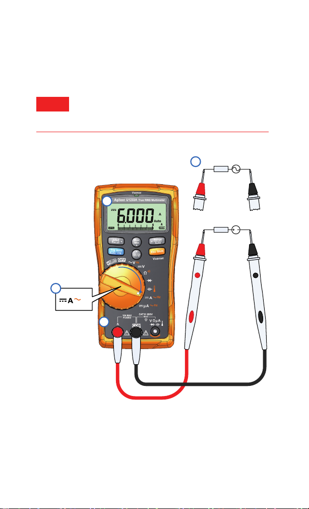
4
1
Voltage source
Hz
DC
LOAD
2
3
AC
Voltage source
LOAD
Performing Measurements
Current measurement (up to A)
Always use the proper function. range, and terminals for
current measurements. Set the positive input terminal to
the A terminal for currents above 600
μA.
12 U1231A/U1232A/U1233A Quick Start Guide
Page 13
U1231A/U1232A/U1233A Handheld Multimeter
WARNING
DC
Hz
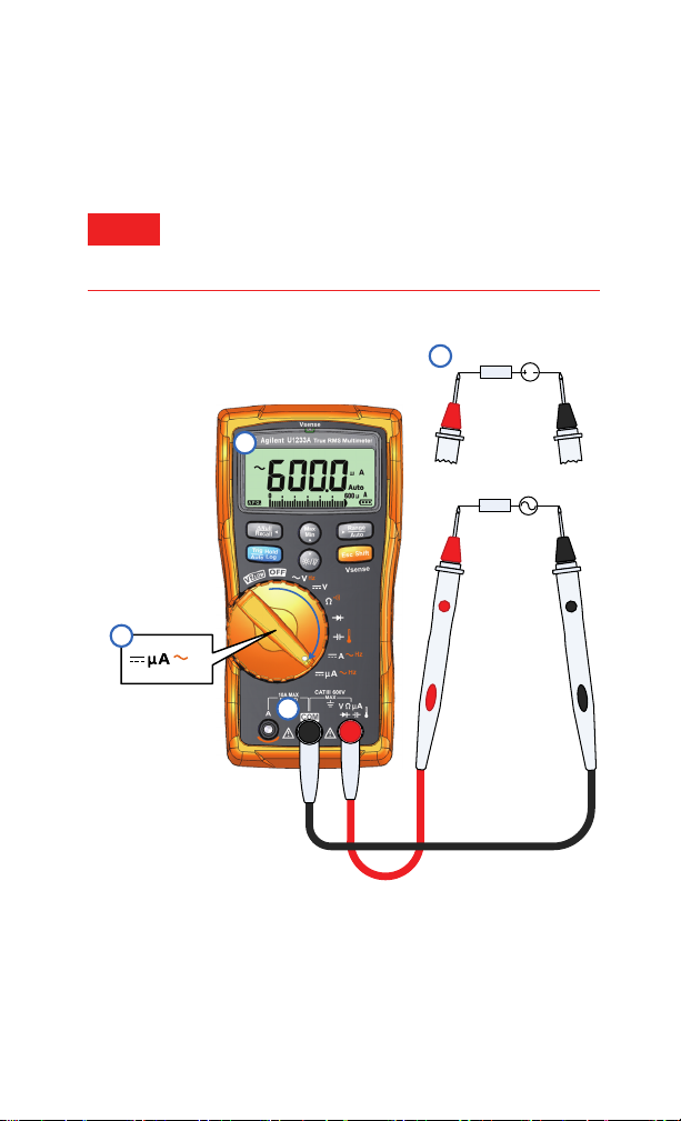
2
4
1
AC
Voltage source
LOAD
3
Voltage source
LOAD
Performing Measurements
Current measurement (up to μA)
Always use the proper function. range, and terminals for
current measurements. Set the positive input terminal to
μA terminal for currents below 600 μA.
the
U1231A/U1232A/U1233A Quick Start Guide 13
Page 14

U1231A/U1232A/U1233A Handheld Multimeter
4
1
3
Adjacent unused wiring
2
Energized wiring
NOTE
Performing Measurements
VZ
measurement
LOW
Ghost voltages can be caused by capacitive coupling between
energized wiring and adjacent unused wiring. Use the VZ
function to eliminate ghost or induced voltages in your measurements.
14 U1231A/U1232A/U1233A Quick Start Guide
LOW
Page 15

Contacting Agilent
CAUTIONCAUTION
WARNING
CAT III
600 V
To obtain service, warranty or technical assistance, contact us at the following phone numbers:
• United States Call Center: 800-829-4444
• Canada Call Center: 877-894-4414
• China Call Center: 800-810-0189
• Europe Call Center: 31-20-547-2111
• Japan Call Center: (81) 426-56-7832
For other countries, contact your country’s Agilent support organization.
A list of contact information for other countries is available on the Agilent
Web site: www.agilent.com/find/assist
Safety Notices Safety Information
A CAUTION notice denotes
a hazard. It calls attention
to an operating procedure,
practice, or the like that, if
not correctly performed or
adhered to, could result in
damage to the product or
loss of important data. Do
not proceed beyond a CAU-
TION notice until the indicated conditions are fully
understood and met.
A WARNING notice
denotes a hazard. It calls
attention to an operating
procedure, practice, or the
like that, if not correctly
performed or adhered to,
could result in personal
injury or death. Do not proceed beyond a WARNING
notice until the indicated
conditions are fully understood and met.
This meter is safety-certified in compliance
with EN 61010-1 (IEC 61010-1:2001) for
CAT-III 600 V, Pollution Degree II Environment. EMC designed in compliance with
EN61326-1. Use with standard or compatible
test probes.
Safety Symbols
Earth (ground) terminal
Equipment protected
throughout by double insulation or reinforced insulation
Caution, risk of electric
shock
Caution, risk of danger (refer
to the instrument manual for
specific Warning or Caution
information)
Category III 600 V overvoltage protection
Agilent U1231A/U1232A/U1233A Handheld Multimeter User’s Guide.
For further safety information details, refer to the
Page 16

Printed in Malaysia
First Edition, March 1, 2011
© Agilent Technologies, Inc., 2011
U1231-90023
Agilent Technologies
 Loading...