


Practical Use of SpectrAA Series for
Multielement Analysis
Author
Brian D. Frary
Application Note
Atomic Absorption
Introduction
The SpectrAA system is designed for automatic multi-element analysis in flame furnace and hydride modes, up to 12 elements in 67 samples (45 in furnace mode) with
minimum operator supervision. When operating in the flame mode an operator
should be near at hand but can be carrying out other tasks.
When operating in the furnace mode the system can be left unattended as there are
no flammable gases and no exposed ignition source hence it can be left to operate
overnight.
A scenario is described for analysis by flame and shows how even a very complex
analytical program is easily handled by the SpectrAA.
The components of the system are:
SpectrAA-30 or SpectrAA-40 Atomic Absorption
Spectrophotometer
PSC-56 Programmable Sample Changer
GTA-96 Graphite Tube Atomizer
VGA-76 Vapor Generator Accessory
DS-15 Data Station
The above units except for the DS-15, are only fitted with an on/off power switch.
Programming and control of each unit in the system is through the DS-15 keyboard
but no computer programming knowledge is required by the operator. In fact the
system is designed for one finger operation using the “fill in the form” (F.I.T.F)
method developed by Agilent Technologies.

2
required (from 0.1% to 99.9%) and set a default time (1 to 500
seconds) for the system to achieve this. If the system is
unable to achieve the precision within the default time specified, measurement will stop and the precision achieved
printed out with the result. (The smaller the absorbance
signal the longer the measurement time required to obtain a
given precision).
This facility is extremely useful when high precision is required
but the element concentration (and thus absorbance) is
expected to vary widely. The operator can set the default time
for the lowest expected absorbance knowing that higher
absorbances will be read in a shorter time with no loss of
precision or waste of analysis time.
The concentrations of lead are expected to be low thus the
air-acetylene burner will be used to obtain higher sensitivity.
(NOTE When high sensitivity is not required a burner change
can be avoided by using a nitrous oxide-acetylene burner for
an air-acetylene flame. This eliminates programming a
“Pause” to change burners). PROMT mode could be used for
measurement but in this case the mean of three replicate
readings of 7-second integration is sufficient for the analytical
requirements.
Chromium forms ferro-chrome compounds in the air-acetylene flame and will therefore be determined using the nitrous
oxide-acetylene flame. This flame will also be used to determine molybdenum and silicon. All three elements will be
determined using five second integration and three replicates.
A delay of five seconds is programmed when using continuous aspiration so that each solution will be aspirated for five
seconds before any readings are taken. This ensures that the
previous solution is washed out of the nebulizer/burner
system. Cross contamination is prevented and the determinations will be more accurate. In addition a RINSE RATE and
RINSE TIME may be programmed if required (where sample
concentrations cover a wide range).
RECALIBRATION RATE and/or RESLOPE RATE are selected
on previous experience with the samples and elements.
Typical values could be reslope 10, recalibration 20.
Up to five standards may be used for each element calibration. 5 mixed standards will be loaded into the sampler
carousel, but the number used will vary from element to
element (see Table 1).
Versatility and ease of use has been achieved in the system
design. The user friendly programming is designed to lead the
operator through the correct procedures.
At power up the DS-15 screen displays 3 modes of operation.
The operator selects one mode using the soft keys labelled:
DEVELOP METHOD
MODIFY METHOD
AUTOMATIC RUN
DEVELOP METHOD used by a chemist to set up and store
methods for the use of other staff.
MODIFY METHOD used in a similar manner.
AUTOMATIC RUN used for routine automatic analysis.
Flame Analytical Procedure
The following scenario shows how aII the facilities of the
system may be used to perform a complex analytical program.
A laboratory has the following samples for analysis:
• 20 steel samples for the determination of chromium,
copper, lead, manganese, molybdenum, nickel and silicon.
• 10 water samples for the determination of iron, sodium
and arsenic.
• 10 slag samples for the determination of calcium, iron
and silicon.
Steel Samples
Analytical method development has shown that most of the
elements in the steel samples can be determined by normal
calibration using mixed standards containing iron. The
SpectrAA- will be calibrated in the concentration mode using
the integration measurement mode for these elements.
Chromium and nickel concentrations must be determined
accurately over a narrow range and bracketing standards calibration will be used for these determinations. High precision
of measurement is also required thus PROMT mode will be
used.
PROMT is Precision Optimised Measurement Time. This
allows the operator to specify the precision of measurement
3
Water Samples
EPA methods specify standard additions calibration for water
analysis. Iron will be determined by this method using the airacetylene flame burning on a nitrous oxide-acetylene burner.
Continuous aspiration would normally be used for water samples but in this case the program “Fe in Slag” will be used
which uses the micro-sampling technique. Thus two different
sample types can be run on one program, the recalibration
rate being defined by the number of water samples.
Arsenic will also be determined by standard additions calibration but using hydride generation. Sodium will be determined
by EMISSION using normal calibration.
Two addition standards will be prepared from sample 1 and
used to produce the calibration graph. The other 9 samples
will be measured against this calibration because the matrices will be very similar.
Slag Samples
As the matrices will be complex and variable all elements will
be determined using STANDARD ADDITIONS calibration. The
dissolved solids concentration will be very high therefore continuous aspiration will not be used. Instead, the MICRO-SAMPLING feature of the PSC-56 will be used and measurements
made in peak height mode.
In micro-sampling the sampling probe dips into the solution
for a programmed time. During this time a certain volume of
liquid is drawn into the flame, the longer the time the greater
the volume (for a one second dip about 350 µL). An integration “window” of eight seconds is set on the system. This
allows enough time for the solution to travel through the nebulizer/burner system into the optical path to be measured. A
volume of 200 µL or more will give the same signal as continuous aspiration, 100 µL will give about 80% and 50 µL about
50% of the continuous aspiration signal. Micro-sampling is
also useful when only small volumes of sample are available
[1,2,3,4].
A RINSE between each sample and a SAMPLE FLUSH will
also be programmed. Using sample flush the probe dips into a
solution for half a second, the slug of liquid is drawn through
the capillary “flushing out” any traces of the previous solution
aspirated: no measurement is made on this solution. After
about 10 seconds the probe dips into the solution for the
specified dip time and the signal produced is measured.
Iron will be determined using the air-acetylene flame, silicon
and calcium using the nitrous oxide-acetylene flame, both
flames being run on the nitrous oxide-acetylene burner.
Typical system parameters for some elements are shown in
Figures 1 to 6.
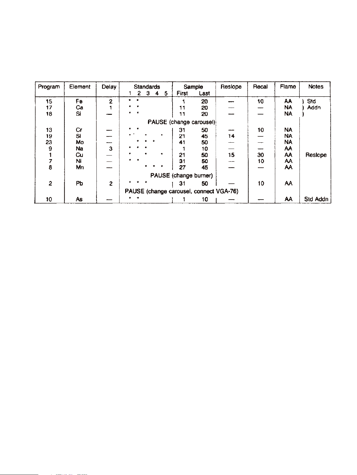
Table 1.
Although RECAL will not be used for program 1, it is included here as it is part of the stored program.
AA = Air-Acetylene
NA = Nitrous Oxide-Acetyleen

4
Figure 1.
Figure 2.
Figure 3.
Figure 4.
Figure 5.
Figure 6.

5
A DELAY of two minutes is programmed at the start of the
first program (15 iron) to ensure the burner is stabilized at its
operating temperature. FIRST and LAST sample numbers are
then entered, in this example 1 and 20.
The FIRST MEASUREMENT can be a calibration, a reslope or
sample.
If CALIBRATION is selected the system will calibrate with the
number of standards specified. If RESLOPE is selected this
will be applied to the stored calibration for that element. If
SAMPLE is selected the concentration values will be calculated from the stored calibration data. If there is no stored calibration then only the absorbance is measured. (Only copper
will be determined using a previously stored calibration and
thus the first measurement will be reslope.)
For the next program (17, calcium) a delay of 1 minute has
been entered to allow the burner to reach its operating temperature with the nitrous oxide-acetylene flame. First and last
sample numbers are entered as before. This procedure is followed for programs 18 (silicon), 13 (chromium), 19 (silicon)
and 23 (molybdenum) but without the delay time.
A delay of three minutes is entered for program 9 (sodium) which
will allow the burner to cool down to its operating temperature;
first and last sample numbers being entered as before.
Sample numbers are entered for program 1 (copper) and first
measurement is altered to RESLOPE. Sample numbers are
entered for programs 7 (nickel) and 8 (manganese).
A delay of two minutes is entered for program 2 (lead) to
allow the burner to reach its operating temperature as it will
be changed before this determination. The relevant sample
numbers are then entered for program 2 and 10 (arsenic).
The final entry to be made is PAUSE AFTER PROGRAM which
appears at the bottom of the screen. This PAUSE facility can be
used several times in a sequence, enabling carousels, standards
and reslope standards to be replaced; burners to be exchanged,
rotated, or their height adjusted; the VGA-76 to be fitted. Lamps
can also be exchanged if nine or more elements are being
determined and multi-element lamps are not being used.
The first PAUSE entry will be 18 which will enable the
carousels to be exchanged. When the system automatically
pauses after the completion of program 18, the operator can
insert the next PAUSE request, in our example 8, to change
the burner. Finally when this second pause command is acted
upon during operation the operator can insert the last PAUSE
request, in our example 2, to enable the VGA-76 to be
installed.
Programming the Automatic Run
It will be useful to draw up a table (Table 1) when planning
the analysis. This can then be used when compiling the
sequence control page on the DS-15 (Figure 8).
Elements requiring standard additions calibration will be
determined first.
AUTOMATlC RUN soft key is pressed and SEQUENCE SELECTION page (Figure 7) is displayed. The relevant programs are
selected on this page and the soft key for SEQUENCE CONTROL pressed. The programs selected are displayed by
number and title on the left side of the screen (Figure 8).
Figure 7.
Figure 8.

6
Having completed the sequence control page the NOTES soft
key is pressed then the REPORT FORMAT soft key. This
screen enables the following to be displayed and printed on
the report:
Operator name
Date
Batch name
and the report parameters selected:
Format Sequential* or Multi-element
Data printed Mean Concentration only* or
Mean Concentration and %RSDor
Mean Concentration, %RSD & Mean
Absorbance or
Each Reading (Mean Concentration,
%RSD, Mean Absorbance and Every
Absorbance Reading).
Print During Run* or After Run or Manual
Instrument status Yes or No*
Notes Yes or No*
Calibration results Yes* or No
Calibration graph Yes or No*
Sample labels Yes* or No
Lines per page Select for page length used (usually 66)
See Figure 9. Parameters normally used are indicated by *.
If PRINT DURING RUN is selected then all the other features
selected will be printed during the run. All results obtained
after the start of the run can be inspected on the print-out.
However when using PRINT MANUAL or PRINT AFTER RUN,
only the results currently displayed on the screen are available
for inspection.
The analytical run can be completed in a slightly shorter time
if PRINT MANUAL is selected.
The absorbance values of all solutions are stored on the program disc as they are read (no matter which PRINT status is
selected). If a power failure occurs during the analysis the
only data lost will be that for the solution under analysis. No
other data is lost or corrupted.
At the end of the analytical run all the data may be archived
and a multi-element report produced. It is recommended that
the data is archived before another run is performed as the
program disc is cleared of data when START is pressed.
If SAMPLE LABELS is selected then a screen as shown in
Figure 10 is displayed (up to 12 alphanumeric characters can
be used). INCREMENT LABELS is a time saving facility. In
Figure 10, W113 is the first water sample and is entered as
sample 1. INCREMENT LABELS is pressed and samples 2 to
10 are automatically labelled W114 to W122. The cursor is
moved to sample 11, relabelled SL536 and INCREMENT
LABELS pressed. Samples 12 to 20 are automatically labelled
SL537 to SL545. Finally the cursor is moved to sample 21,
relabelled S907 and INCREMENT LABELS pressed. Samples
22 to 42 are automatically labelled S908 to S928. MORE
LABELS is pressed, samples 43 to 67 are displayed and are
automatically labelled S929 to S953.
Loading Off Carousels
Two carousels will be used, one for STANDARD ADDITIONS
calibration (water samples 1 to 10, slag samples 11 to 20), the
other for NORMAL calibration (steel samples 21 to 50).
The standard additions carousel will be loaded as follows:
Figure 9.
Figure 10.

7
Sample position 1 Blank
2 Addition 1
3 Addition 2
4 Addition 0 (sample 1)
5 to 13 Addition 0 (samples 2 to 10)
14 Blank
15 Addition 1
16 Addition 2
17 Addition 0 (sample 11)
18 to 26 Addition 0 (samples 12 to 20)
The second carousel, for normal calibration will be loaded:
Multi-element standards in standard positions 1 to 5. Blank
and reslope solutions in their respective positions. Water
samples in sample positions 1 to 10 and steel samples in
positions 21 to 50.
Operation
When the operator has fitted the required burner and
carousel the flame is lit and START key pressed.
Operation proceeds as foIlows:
The system recalls the first program in the sequence (15)
resets the sampler and checks all system parameters are correctly set. It waits 2 minutes for the burner to warm up while
aspirating distilled water. It then carries out the calibration of
the system with the addition standards for waters and measures the first 10 samples (waters). It then recalibrates the
system with the addition standards for slags and measures
samples 11 to 20 (slags).
The next program (17) is recalled and the system set up to
these parameters. The burner is allowed to warm up for the
programmed 1 minute before calibration proceeds. Samples 1
to 10 are then measured.
The next program (18) in the sequence is recalled and the
system set up on these parameters. Calibration proceeds
immediately as no delay has been programmed (the burner is
already at its operating temperature). Samples 1 to 10 are
measured for this element.
After sample 10 is measured the next program (13) is recalled
and the system “beeps” to remind the operator that a programmed PAUSE has been reached. The operator presses
STOP, changes carousels, alters PAUSE AFTER PROGRAM to
8 and presses START. As no delay has been programmed the
system proceeds to calibrate and then measures samples 31
to 40. A RECALIBRATION is then carried out and samples
41 to 50 are measured.
Program 19 is then recalled, the system set up, calibration is
performed and samples 21 to 35 are measured. RESLOPE is
performed and samples 36 to 45 measured.
Program 23 is recalled, the system set up, calibration is performed and samples 41 to 50 measured.
Program 9 is recalled, the system is set up and changes to
the air-acetylene gas mixture waiting for the 3 minutes programmed delay while the burner cools down to its operating
temperature. Calibration is performed and samples 1 to 10 are
measured.
Program 1 is recalled, the system set up, a RESLOPE is performed and applied to the stored calibration. If the reslope is
correct, samples 21 to 36 are measured. A RESLOPE is
performed and samples 37 to 50 measured.
Program 7 is recalled, the system set up, calibration is performed and samples 31 to 40 measured. A RECALIBRATION is
performed and samples 41 to 50 measured.
Program 8 is recalled, the system set up, calibration is performed and samples 27 to 45 measured. Program 2 is recalled
and the system “beeps” to remind the operator that a programmed PAUSE has been reached. The operator presses
STOP, presses FLAME OFF, changes burners, alters PAUSE
AFTER PROGRAM to 2 then presses IGNITE and START. The
system waits 2 minutes for the burner to warm up then calibrates and measures samples 31 to 40. A RECALIBRATION is
then carried out and samples 41 to 50 are measured.
Program 10 is recalled and the system “beeps” to remind the
operator that a programmed PAUSE has been reached. The
operator presses STOP and FLAME OFF, connects the VGA-76
hydride generator, replaces the carousel in use by the one for
standard addition calibration and presses IGNITE. START is
pressed, the system performs the calibration procedure and
determines the arsenic concentrations of samples 1 to 10.
After the last sample is determined the flame is automatically
extinguished and the system “beeps” indicating the analytical
run has been completed.
Archiving and multi-element report
The INDEX key is pressed and page 19 UTILITIES selected.
From the display ARCHIVE is selected followed by the file (on
the utilities disc) for archiving. The ARCHIVE soft key is
pressed and the data is permanently stored.
After returning to the UTILITIES index, PRINT REPORTS is
selected. From the next display the data set required is
chosen and then the elements required. REPORT FORMAT
soft key is pressed and the following is displayed:

8
Format Sequential or multi-element*
Data printed Mean concentration only* or
Mean concentration and %RSDor
Mean concentration, %RSD and mean
absorbance or
Each Reading (Mean Concentration,
%RSD, Mean Absorbance and Every
Absorbance Reading).
Instrument status Yes or No*
Notes Yes or No*
Calibration results Yes* or No
Calibration graph Yes or No*
Sample labels Yes* or No
Weight correction Yes* or No
Lines per page Select for page length used (usually 66)
Parameters normally used are indicated by *
If WEIGHT CORRECTION is selected the measured concentration of the elements in the samples is automatically calculated before print out. This is a time (and error) saving facility.
PRINT REPORT is pressed and the multi-element report is
duly obtained (Figure 11).
Figure 11.

9
As all the analytical data is now archived other reports can be
generated at any time if required. For example a report showing all data for arsenic (program 25) is required. This is easily
produced by:
• Accessing the utilities disc, selecting the appropriate
archive file, then selecting the element to be printed (in
this case arsenic). Proceed to report format via the soft
key and select the options required, then print report.
• The SpectrAA- system can be used for an automatic run
in the same way. However as it has a manually operated
turret the operator must bring the next lamp into the
operating position when prompted by the DS-15. If multielement lamps are used then this requirement is reduced
or even eliminated.
References
1. L. M. Voth, “Analysis of High Dissolved Solids Solutions
by Flame Microsampling”, Varian Instruments At Work
Number AA-13, February 1981.
2. L. M. Voth, “Analysis of Battery Acids by Flame
Microsampling”, Varian Instruments At Work Number
AA-14 April 1981.
3. L. M. Voth, “Determination of Calcium and Magnesium in
Blood Serum by Automated Flame Microsampling”,
Varian Instruments At Work Number AA-15, April 1981.
4. L. M. Voth, “Determination of Chromium, Lead and
Cadmium in Drinking Water by Solvent Extraction and
Flame Microsampling”, Varian Instruments At Work
Number AA-16, August 1981.
For More Information
For more information on our products and services, visit our
Web site at www.agilent.com/chem

www.agilent.com/chem
Agilent shall not be liable for errors contained herein or
for incidental or consequential damages in connection
with the furnishing, performance, or use of this material.
Information, descriptions, and specifications in this
publication are subject to change without notice.
© Agilent Technologies, Inc., 1985
Printed in the USA
November 1, 2010
AA048
 Loading...