

Page 1

SMPTE 310M Interface
Installation Guide
Product Number: E6292A
Document Part Number: E6292-94000 Ed2
ã
Copyright Hewlett-Packard Company 1999, 2000
Page 2

Copyright
© Hewlett-Packard Company 1999, 2000
All rights reserved.
Notice
Warranty
MPEGscope
Pentium®
Printing history
The information contained in this document is subject to change without notice.
HEWLETT-PACKARD MAKES NO WARRANTY OF ANY KIND WITH REGARD TO THIS MATERIAL,
INCLUDING, BUT NOT LIMITED TO, THE IMPLIED WARRANTIES OF MERCHANTABILITY AND FITNESS
FOR A PARTICULAR PURPOSE.
Hewlett-Packard shall not be liable for errors contained herein or for incidental or consequential
damages in connection with the furnishing, performance, or use of this material.
A copy of the specific warranty terms applicable to your product and replacement parts can be obtained
from your local Sales and Service Office.
This product contains technology licensed from David Sarnoff Research Center, Subsidiary of SRI
International.
is a U.S. registered trademark of Intel Corporporation
New editions of this guide are issued to reflect extensive changes made to the software. Revisions may
be issued between editions to correct errors in the manual. A new edition may not be issued with every
application release. The application release, at the date of printing, is noted in the following table.
Manual Name: SMPTE 310M Interface Installation Guide
Product Number: E6292A
Printing Date Manual Part Number
April, 1999 E6292-94000 Ed1
September, 1999 E6292-94000 Ed2
Product support
Contact your local Agilent Technologies representative or contact us at
Agilent Technologies
Advanced Networks Division
PO Box 221
Blackburn, 3130
Victoria, Australia
Phone: +61-3-8877-8633
Fax: +61-3-8877-5550
Email: y900_support@agilent.com or dv-support@agilent.com
Web: http://advanced.comms.agilent.com/mpegscope
Printed in Canada
Page 3

Certification
Agilent Technologies certifies that this
product met its published specifications at the
time of shipment from the factory. Agilent
Technologies further certifies that its
calibration measurements are traceable to the
United States National Institute of Standards
and Technology (formerly National Bureau of
Standards), to the extent allowed by that
organization’s calibration facility, and to the
calibration facilities of other International
Standards Organization members.
Additional Information for Test and
Measurement Equipment
To comply with EMC regulations, shielded
cables should be used on all appropriate
connections. Otherwise, the user has to
ensure that, under operating conditions, the
Radio Interference Limits are still met at the
border of the user's premises.
Warnings
The following general safety precautions
must be observed during all phases of
operation, service, and repair of this product.
Failure to comply with these precautions or
with specific warnings elsewhere in this
manual violates safety standards of design,
manufacture, and intended use of the
product. Agilent Technologies assumes no
liability for the customer’s failure to comply
with these requirements.
Ground the Equipment
Ground the Equipment: For safety, Class 1
Ground the EquipmentGround the Equipment
equipment (equipment having a protective
earth terminal), an uninterruptible safety
ground must be provided from the mains
power source to the product input wiring
terminals or supplied power cable. Before
operating the equipment, guard against
electric shock in case of fault by always using
the provided 3-conductor power cord to
connect the equipment to a grounded power
outlet.
DO NOT use in hazardous environments
DO NOT use in hazardous environments: Do
DO NOT use in hazardous environmentsDO NOT use in hazardous environments
not operate the product in an explosive
atmosphere or in the presence of flammable
gases or fumes. This product is designed for
indoor use only.
DO NOT use repaired fuses or short-circuited
DO NOT use repaired fuses or short-circuited
DO NOT use repaired fuses or short-circuited DO NOT use repaired fuses or short-circuited
fuse holders
fuse holders: For continued protection against
fuse holdersfuse holders
fire, replace line fuses only with fuses of the
same voltage and current rating and type.
Keep away from live circuits
Keep away from live circuits: Operating
Keep away from live circuitsKeep away from live circuits
personnel must not remove equipment covers
or shields. Procedures involving the removal
of covers and shields are for use by servicetrained personnel only. Under certain
conditions, dangerous voltages may exist
even with the equipment switched off. To
avoid dangerous electrical shock, DO NOT
perform procedures involving cover or shield
removal unless you are qualified to do so.
DO NOT operate damaged equipment
DO NOT operate damaged equipment:
DO NOT operate damaged equipmentDO NOT operate damaged equipment
Whenever it is possible that the safety
protection features built into this product
have been impaired, either through physical
damage, excessive moisture, or any other
reason, REMOVE POWER and do not use the
product until safe operation can be verified by
service-trained personnel. If necessary, return
the product to an Agilent Technologies Sales
and Service Office for service and repair to
ensure the safety features are maintained.
DO NOT substitute parts or modify
DO NOT substitute parts or modify
DO NOT substitute parts or modify DO NOT substitute parts or modify
equipment
equipment: Because of the danger of
equipmentequipment
introducing additional hazards, do not install
substitute parts or perform any unauthorized
modification to the product. Return the
product to an Agilent Technologies Sales and
Service Office for service and repair to ensure
features are maintained.
DO NOT clean with fluids
DO NOT clean with fluids: Doing so may
DO NOT clean with fluidsDO NOT clean with fluids
make the equipment unsafe for use. Power
down the equipment and disconnect the
power cord before cleaning. To clean, use a
soft dry cloth.
Safety Symbols
If you see this symbol on a product, you must
refer to the manuals for specific Warning or
Caution information to avoid personal injury
or damage to the product
Indicates the field wiring terminal that must
be connected to ground before operating the
equipment. Protects against electrical shock
in case of fault.
or
Frame or chassis ground terminal. Typically
connects to the equipment’s metal frame.
Alternating current (ac).
Direct current (dc).
Indicates hazardous voltages and potential for
electrical shock.
Indicates that antistatic precautions should be
taken.
This product complies with CSA requirement
CSA 22.2 No. 1010.1, NRTL/C, EN 610101:1993 + A2:1995/IEC 1010-1:1990 +
A1:1992 + A2:1995 Safety requirements for
electrical equipment for measurement,
control, and laboratory use.
Notice for European Community: This product
complies with the relevant European legal
Directives: EMC Directive 89/336/EEC and
Low Voltage Directive 73/23/EEC.
Das CE-Zeichen zeigt die Übereinstimmung
mit allen für das Produkt geltenden Direktiven
der Europäischen Union an.
ISM 1—A
This is the symbol for an Industrial, Scientific,
and Medical Group 1 Class A product.
i
Page 4
Dieses Zeichen steht für ein Produkt der
Gruppe 1, Klasse A, für den Einsatz im
industriuellen, wissenschaftlichen und
medizinischen Bereich.
This product meets the requirements of the
Australian EMC Framework (AS/NZS
2064.1/2 for ISM:1A), enforced by the
Radiocommunications Act 1992.
WARNING
Calls attention to a procedure, practice, or
condition that could cause bodily injury or
death.
CAUTION
Calls attention to a procedure, practice, or
condition that could possibly cause damage to
equipment or permanent loss of data.
Certification
Agilent Technologies certifie que cet
instrument est conforme aux spécifications
publiées au moment de sa sortie d’usine.
Agilent Technologies atteste en outre qu’il est
possible de trouver référence à ses mesures
d’étalonnage auprès de l’organisme de
normalisation américain “United States
National Institute of Standards and
Technology” (auparavant National Bureau of
Standards), dans la mesure des possibilités
autorisées par cet organisme, et dans celles
autorisées par d’autres membres de
l’Organisation Internationale de
Normalisation.
Informations complémentaires
relatives à l ‘équipement de test et
de mesure
Conformément aux réglementations
concernant la compatibilité
électromagnétique, il convient d’utiliser des
câbles blindés sur toutes les connexions
appropriées. S’il n’emploie pas ce type de
câble, l’utilisateur doit vérifier qu’en condition
d’exploitation les interférences radio sont
encore acceptables à la limite de ses locaux.
Avertissement
Les précautions générales de sécurité ci-
dessous doivent être observées au cours de
toutes les phases d’exploitation, de
maintenance et de réparation de l’instrument.
Le non-respect de ces précautions ou
d’avertissements spécifiques cités ailleurs
dans le manuel entraîne la violation des
normes de sécurité relatives à la conception,
la fabrication et l’utilisation prévue de cet
instrument. Agilent Technologies n’assume
aucune responsabilité en cas de non-respect
de ces exigences.
Mise à la terre de l’équipement: en vue de
garantir la sécurité, pour l’équipement de
classe 1 (comportant une borne mise à la
terre de protection), une mise à la terre
permanente doit être assurée de la source
d’alimentation secteur aux bornes de câblage
d’entrée de l’instrument ou au câble
d’alimentation fourni. Avant d’utiliser
l’équipement, évitez les chocs électrostatiques
en cas de défaillance de l’instrument en
utilisant toujours le cordon d’alimentation 3
conducteurs fourni pour brancher
l’équipement à une prise de terre.
N’UTILISEZ PAS dans un environnement à
risque : N’utilisez pas l’instrument dans des
conditions de risques d’explosion ni en
présence de gaz ni d’émanations
inflammables. Cet instrument est conçu
exclusivement pour un usage intérieur.
N’UTILISEZ PAS de fusibles usagés ni de
porte-fusibles en court-circuit: Pour une
protection permanente contre le feu,
remplacez les fusibles uniquement par des
fusibles de même tension, de même calibre et
de même type.
Tenez vous à l’écart des circuits sous tension:
Le personnel d’exploitation ne doit pas retirer
les capots ni les blindages. Les procédures
impliquant ces manipulations doivent être
exécutées exclusivement par un personnel
formé à la maintenance. Dans certaines
conditions, des tensions dangereuses peuvent
être générées même lorsque l’équipement
n’est pas sous tension. Afin d’éviter tout
risque d’électrocution, N’EXÉCUTEZ PAS de
procédure nécessitant la manipulation des
capots et des blindages sans qualification à
cet effet.
N’UTILISEZ PAS d’équipement endommagé:
Si les caractéristiques de l’instrument
relatives à la sécurité ont été atteintes, que
ce soit en raison d’un dommage physique,
d’une humidité excessive, ou pour toute autre
cause, METTEZ L’EQUIPEMENT HORS
TENSION et ne l’utilisez plus jusqu’à ce que la
sécurité de son fonctionnement puisse être
vérifiée par un personnel formé à la
maintenance. Si nécessaire, retournez
l’instrument à un bureau commercial et de
service après-vente Agilent Technologies pour
le faire réparer et garantir ses caractéristiques
de sécurité.
NE REMPLACEZ PAS de pièce ni ne modifiez
l’équipement: En raison des risques
supplémentaires que cela implique, n’installez
pas de pièce de remplacement ni n’exécutez
aucune modification non autorisée sur
l’instrument. Retournez-le à un bureau
commercial et de service après-vente Agilent
Technologies pour le faire réparer et garantir
ses caractéristiques de sécurité.
NE NETTOYEZ PAS avec des produits
liquides: L’emploi de produits liquides peut
être risqué. Mettez l’équipement sous tension
et débranchez le cordon d’alimentation avant
le nettoyage. Utilisez un chiffon doux et sec.
Symboles de sécurité
Si vous apercevez ce symbole sur un
instrument, vous devez vous référer aux
manuels pour de plus amples informations
concernant les notes Avertissement et
Attention en vue d’éviter des blessures
corporelles ou des dommages à l’instrument.
Indique la borne de câblage qui doit être
connectée à la terre avant la mise en route de
l’équipement. Protège contre les
électrocutions en cas de défaillance de
l’instrument.
ii
Page 5
Borne de mise à la terre de cadre ou de
châssis. Connectée en principe au cadre
métallique de l’équipement.
ou
Dieses Zeichen steht für ein Produkt der
Gruppe 1, Klasse A, für den Einsatz im
industriuellen, wissenschaftlichen und
medizinischen Bereich.
Courant alternatif (ca).
Courant continu (cc).
Indique une tension dangereuse et des risques
d’électrocution.
Indique que des précautions anti-statiques
doivent être prises.
.
Cet instrument satisfait aux spécifications
CSA 22.2 No. 1010.1, NRTL/C, EN 610101:1993 + A2:1995/IEC 1010-1:1990 +
A1:1992 + A2:1995 en matière de sécurité
pour les équipements électriques de mesure,
de contrôle et de laboratoire.
Label européen: cet instrument est conforme
aux directives européennes suivantes: EMC
89/336/EEC et basse tension 73/23/EEC.
Das CE-Zeichen zeigt die Übereinstimmung
mit allen für das Produkt geltenden Direktiven
der Europäischen Union an.
Cet instrument est conforme aux
spécifications de l’Australian EMC Framework
(AS/NZS 2064.1/2 for ISM:1A), mises en
oeuvre par le Radiocommunications Act de
1992.
AVERTISSEMENT
AVERTISSEMENT
AVERTISSEMENTAVERTISSEMENT
Attire l’attention sur une procédure, pratique
ou condition comportant un risque de
blessure ou d’électrocution.
ATTENTION
ATTENTION
ATTENTIONATTENTION
Souligne qu’une procédure, pratique ou
condition peut entraîner des dommanges à
l’équipement ou la perte permanente de
données.
ISM 1—A
Ce symbole indique que l’instrument est un
instrument de type Industriel Scientifique et
Médical Groupe 1 Classe A.
iii
Page 6

Page 7

Right
Contents
Introduction .................................................................................................................................................................... 1
top margin for modules
MPEGscope Plus and MPEGscope Lite .................................................................................................. 3
Step 1: Remove the cover ......................................................................................................................................... 4
Step 2: Remove optional interface.......................................................................................................................... 6
Step 3: Install SMPTE interface .............................................................................................................................. 8
Step 4: Replace the cover........................................................................................................................................ 10
body text drop
MPEGscope Portable and Portable Lite.............................................................................................. 12
Step 1: Remove the cover ....................................................................................................................................... 13
Step 2: Remove optional interface........................................................................................................................ 15
Step 3: Install SMPTE interface ............................................................................................................................ 16
Step 4: Replace the cover........................................................................................................................................ 18
Connecting to the SMPTE 310M interface........................................................................................ 20
Configuring the software .................................................................................................................................. 21
SMPTE 310M interface specifications .................................................................................................. 24
Release Notes............................................................................................................................................................... 25
page inner margin
hanging column right margin
body text left margin
body text bottom margin
footer rulling line
footer text base line
Contents–1
outer margin for text and artwork
Page 8

Page 9

Introduction
Introduction
The E6292A SMPTE (Society of Motion Picture and Television Engineers) 310M
interface is serial-to-parallel converter that receives a synchronous serial SMPTE
signal and converts it to a DVB-Synchronous Parallel Interface (DVB-SPI) signal.
This DVB-SPI signal is then output to the DVB-SPI receiver on the MPEGscope
main card via an external cable which is included with your installation kit. The
SMPTE 310M interface enables you to test the connectivity of multiplexers and
transmission equipment carrying ATSC-compliant transport streams.
This manual shows how to install the SMPTE 310M interface card into your
MPEGscope Plus, MPEGscope Lite, MPEGscope Portable, or MPEGscope
Portable Lite test system. Each step provides photographs and easy-tounderstand explanations. The manual also includes illustrations and physical
specifications for the interface and connectors.
Installation kit Before beginning, ensure that your SMPTE 310M interface installation kit contains
the following items:
• SMPTE 310M Interface Installation Guide (E6292-94000)
• SMPTE 310M Interface Printed Circuit Assembly (E6292-66501)
• DVB-SPI Y-Adapter Cable (E6292-64300)
• Size 15 Torx Head Screwdriver (8710-1622)
• Antistatic Wrist Strap (9300-1408)
1
Page 10

Introduction
For more help... If you have any questions about the installation procedure, call your local HP
representative. You can also contact digital video customer support at the
following numbers:
Location Number
North, Central, South America 1 800 698 0061 or (719) 531 4589
Asia-Pacific 1 800 375 8100 or (65) 272 5293
Europe, Africa, Middle East +31 20 547 9900 or +33 69 29 41 14
Japan 0120 421 345 or +81 426 56 7799
If you prefer to email your question, please write to digital video customer support
at this address:
Email dv-support@hp.com
2
Page 11
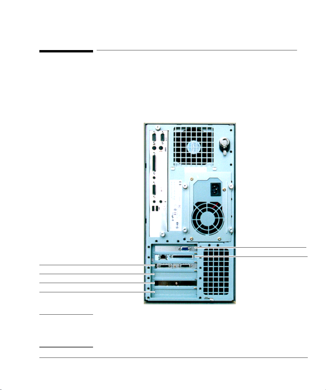
MPEGscope Plus (E6277C)
MPEGscope Plus and MPEGscope Lite
MPEGscope Plus and MPEGscope Lite
This section explains how to install the SMPTE 310M interface into the
MPEGscope Plus or Lite models. Normally, you will install the interface into slot 3,
the optional line interface slot. If you have a different MPEGscope PC than the
one illustrated below, you can still follow the procedure described in this section,
as the affected cards are installed in the same slot positions.
slot 6—video card
slot 5—PCI LAN card
slot 4—MPEGscope main card
slot 3—optional line interface slot
slot 2—Real-time Analyzer card
slot 1—(empty)
Note If your MPEGscope is housed in a Kayak XU PC and you also have another
optional interface (such as the ASI & Serial ECL (DHEI) interface), you can
rearrange the cards so that both the SMPTE 310M and the optional interface are
installed at the same time. This alternative configuration is shown on page 9.
3
Page 12

MPEGscope Plus and MPEGscope Lite
Step 1: Remove the cover
WA R N I N G Never remove the computer cover without first removing the power cord from the
power outlet and any connection to a telecommunications network.
Power off your PC.
1
Unplug the AC power cord from the
2
rear of the PC.
If you are connected to a
3
telecommunications network,
disconnect the network cable.
If you are connected to a system
4
under test, disconnect the line
interface cable(s).
4
Page 13

MPEGscope Plus and MPEGscope Lite
Grasp the cover on the sides at the back
6
of the computer and slide it forwards and
off the computer.
Flip the two latches on the front sides
5
of the computer cover upwards.
5
Page 14

MPEGscope Plus and MPEGscope Lite
Step 2: Remove optional interface
Complete this step if your MPEGscope already has an optional interface installed
and you want to replace it with the SMPTE 310M interface. For an alternative
card configuration, refer to page 9.
IMPORTANT:
Attach the antistatic wrist strap to your wrist and to the PC chassis as described in the
1
instructions on the envelope. Ensure that the copper foil end of this strap attaches to an
electrical ground.
Back of computer
with connectors and
faceplates
Lay the computer on
2
its side so that you
can access the
cards from the top.
6
Page 15

MPEGscope Plus and MPEGscope Lite
If your optional line interface is connected to the
6
MPEGscope main card with a cable, disconnect the other
end of the cable from the MPEGscope main card and
remove the cable.
If your optional line interface is connected to the
4
MPEGscope main card with a cable, disconnect the
cable from the optional interface card.
Remove the faceplate screw from slot 3
5
with the screwdriver provided, then
remove the optional line interface.
If your MPEGscope has a Real-time Analyzer, disconnect
3
the ribbon cable from the Real-time Analyzer card. The
cable runs from the MPEGscope main card to the Realtime Analyzer card.
7
Page 16

MPEGscope Plus and MPEGscope Lite
Step 3: Install SMPTE interface
IMPORTANT:
Install the SMPTE 310M interface card into slot 3 and screw the
2
faceplate to the PC chassis. (If this is the first interface installed
into slot 3, you will have to remove the blank faceplate first.)
Attach the antistatic wrist strap to your wrist and to the PC chassis as described in the instructions on the
1
envelope. Ensure that the copper foil end of this strap attaches to an electrical ground.
If your MPEGscope has a Real-time Analyzer,
3
reconnect the ribbon cable from the MPEGscope main
card to the Real-time Analyzer card.
8
Page 17

MPEGscope Plus and MPEGscope Lite
Alternative
configuration
Remove the cards from slots 2, 3 and 4, disconnecting cables as necessary.
1
Attach the IAB ribbon cable to
3
the MPEGscope main card then
install the card into slot 3.
This configuration applies only if your MPEGscope is housed in a Kayak XU PC
(e.g., E6277B or E6277C). It enables you to have both the SMPTE 310M interface
and another optional line interface (e.g., the ASI & Serial ECL (DHEI) interface)
installed at the same time. The configuration requires repositioning all
MPEGscope cards into the first four slots, and replaces Steps 2 and 3 on pages 6
to 8. Follow all other steps as usual.
Install the SMPTE 310M
6
interface card into slot 4.
Connect the IAB ribbon cable from
5
the MPEGscope main card to the
optional line interface (e.g., the ASI
& Serial ECL (DHEI) interface).
Remove the blank faceplate
2
and install the Real-time
Analyzer card into slot 1.
Install the optional line
4
interface (e.g., the ASI &
Serial ECL (DHEI) interface)
into slot 2.
Connect the ribbon cable from
7
the MPEGscope main card to the
Real-time Analyzer card.
9
Page 18

MPEGscope Plus and MPEGscope Lite
Step 4: Replace the cover
10
Slide the cover onto the computer, making sure
2
that the two guides at the bottom of the case slide
into the two rails at the base of the computer.
Firmly slide the cover backwards into position.
Ensure that the two latches on the front
1
sides of the cover are lifted up.
Lower the two latches on the front
3
sides of the cover into place.
Reconnect your mouse, keyboard,
4
display, power cables, and LAN
connection, then power on your
MPEGscope.
Page 19

MPEGscope Plus and MPEGscope Lite
MPEG
SMPTE 310M i
d
scope Plus with
nterface installe
SMPTE 310M interface
installed in slot 3.
11
Page 20

MPEGscope Portable and Portable Lite
E6300C MPEG
scope Portable platform
slot 1—Real-time Analyzer card
slot 2—optional interface slot
slot 3—MPEGscope main card
MPEGscope Portable and Portable Lite
This section explains how to install the SMPTE 310M interface into the
MPEGscope Portable or Portable Lite models. You will install the interface into
slot 2, the optional line interface slot, illustrated below.
slot 4—SCSI card
slot 5—external display and LAN card
12
Page 21

MPEGscope Portable and Portable Lite
Step 1: Remove the cover
WA R N I N G Never remove the computer cover without first removing the power cord from the
power outlet and any connection to a telecommunications network.
Power off your portable.
1
Unplug the AC power cord from the
2
rear of the portable.
If you are connected to a system under test,
3
disconnect the line interface cable(s).
If you are connected to a telecommunications
4
network, disconnect the network cable.
13
Page 22

MPEGscope Portable and Portable Lite
Carefully lay MPEGscope Portable face down
5
with the handle towards you.
screw
#1
screw
#4
Remove the two metal shield screws,
7
then gently pull tabs from slots and
remove the metal shield.
screw
#2
screw
#5
screw
#1
screw
#3
screw
#6
Remove the six back panel screws from
6
the back and side, then lift off the back
panel.
screw
#2
14
tabs
tabs
Page 23

MPEGscope Portable and Portable Lite
IMPORTANT
Step 2: Remove optional interface
Complete this step if your MPEGscope already has an optional interface installed
and you want to replace it with the SMPTE 310M interface.
:
Attach the antistatic wrist strap to your wrist and to the PC chassis as described in the
1
instructions on the envelope. Ensure that the copper foil end of this strap attaches to an
electrical ground.
If your optional line interface is
5
connected to the MPEGscope main
card with a cable, disconnect the other
end of the cable from the MPEGscope
main card and remove the cable.
If your optional line interface is connected to the
3
MPEGscope main card with a cable, disconnect
the cable from the optional interface card.
Remove the faceplate screw from slot 2
4
with the screwdriver provided, then
remove the optional line interface.
If your MPEGscope has a Real-time Analyzer, disconnect
2
the ribbon cable connector from the Real-time Analyzer
card. The cable runs from the MPEGscope main card to
the Real-time Analyzer card.
15
Page 24

MPEGscope Portable and Portable Lite
Step 3: Install SMPTE interface
IMPORTANT:
Attach the antistatic wrist strap to your wrist and to the PC chassis as described in the instructions on the
1
envelope. Ensure that the copper foil end of this strap attaches to an electrical ground.
16
Install the SMPTE 310M interface card into slot 2 and screw the
2
faceplate to the PC chassis. (If this is the first interface installed
into slot 2, you will have to remove the blank faceplate first.)
Page 25

If your MPEGscope has a Real-time Analyzer,
3
reconnect the ribbon cable from the MPEGscope main
card to the Real-time Analyzer card.
Page 26

MPEGscope Portable and Portable Lite
Step 4: Replace the cover
screw
#2
Insert tabs on the sides of the
1
metal shield into the slots on
the outer frame, then replace
the two metal shield screws.
screw
#1
Place the back cover in
3
position and replace the
six back panel screws.
Reconnect your
4
display, power
cables, and LAN
connection, then
power on your
MPEGscope Portable.
tabs
screw
#4
screw
#1
tabs
screw
screw
#2
#5
A plastic guide for the
2
MPEGscope main card is
located on the inside of the
metal shield (by the third
plastic guide screw). Use a
small screwdriver to push
down the plastic guide until the
edge of the MPEGscope main
card is engaged in the slot on
the guide.
screw
#3
screw
#6
18
Page 27

MPEGscope Portable and Portable Lite
E6300A MPEG
SMPTE 310M i
d
SMPTE 310M interface
installed in slot 2.
scope Portable with
nterface installe
19
Page 28

Connecting to the SMPTE 310M interface
Connecting to the SMPTE 310M interface
DVB–SPI interface on
MPEGscope main board
Connect the output line to
4
your system under test to
the OUT port on the
SMPTE 310 interface.
Connect the SCSI 26-pin
1
male connector labelled
SPI Tx on the DVB–SPI
Y–Adapter cable to the
DVB-SPI Tx port on the
MPEGscope main board.
DVB–SPI Tx DVB–SPI Rx
EXT CLK IN
3
Connect the SCSI
2
26-pin male
connector labelled
SPI Rx on the DVB–
SPI Y–Adapter cable
to the DVB-SPI Rx
port on the
MPEGscope main
board
Connect the single SCSI
50-pin connector on the
DVB-SPI Y-Adapter cable
to the DVB-SPI IN/OUT
port on the SMPTE 310M
interface.
SMPTE 310M interface
To system under test...
20
SMPTE 310M
OUT
IN
DVB–SPI IN/OUT
Connect the input line from
5
E6292A
your system under test to
the IN port on the SMPTE
310M interface.
Page 29

Configuring the software
Configuring the software
Because the SMPTE 310M interface receives and transmits data via the
MPEGscope SPI interface, you do not need special SMPTE 310 interface software.
You can set receiver and transmitter options from the SPI interface application, as
illustrated below.
Select the SPI interface.
1
For information about this dialog, press
the Help button.
21
Page 30

Configuring the software
Select Configure.
2
Select the Mode tab.
3
22
Select the mode to use for
4
your test.
For information about modes, press the
Help button. You can also click on a
field using the right mouse button.
Page 31

Select receiver
6
options.
Select the Tx tab.
7
Select the Rx tab.
5
Configuring the software
Select transmitter
8
options.
Close the dialog.
9
For information about receiver and transmitter options, press
the Help button at the bottom of the dialog. You can also
click on a field using the right mouse button.
23
Page 32

SMPTE 310M interface specifications
Type Biphase mark
Maximum line rate 40 Mb/s
(Minimum receive and transmit rate is 16 Mb/s)
Timestamps Packet timestamp clock: 10 MHz +/- 5 ppm
Resolution of timestamp clock: 100 ns
Packet timestamp sampling is accurate to within +/- 1 timestamp clock period
between consecutive packets
Electrical Spec 800 mV pp (nominal)
Connector Type 75
Standard SMPTE 310M Standard, Sept. 98
Part Number E6292A
WA R N I N G To ensure the Electromagnetic Compatibility (EMC) of MPEGscope, use shielded
cables on all interfaces.
Ω BNC
Page 33

Release Notes
Release Notes
This section describes two SMPTE 310M interface constraints that may affect
your test. It includes a description of the problem along with a simple solution or
workaround.
Initial startup with
sparse streams
Large bit rate changes Because the SMPTE 310M interface implements a wide-band clock recovery
Upon initial startup or when you make a large bit rate change, the SMPTE 310M
receiver may not synchronize if the stream contains large continuous strings of 1’s
or 0’s. This could happen if you are receiving many NULL packets with an all-1 or
all-0 payload (for example, from an idle SPI transmitter). You will notice many Rx
Psync and Rx Clock errors from the SPI LIF dialog.
The problem occurs because the stream does not contain enough variation in bit
values for the SMPTE 310M interface to unambiguously determine the bit rate.
For example, it will not be able to differentiate a stream consisting of all 0’s at 40
Mb/s (where the bit has one transition) from a stream consisting of all 1’s at 20
Mb/s (where the bit has two transitions).
The solution is to play a stream that contains transport stream packets carrying
real data until synchronization occurs. Without changing the bit rate, play the
original stream again. The SMPTE 310M interface will remember the bit rate and
correctly synchronize.
circuit, large bit rate changes (greater than 1 1/2 times the original rate) may
cause the SMPTE 310M receiver to lose synchronization. For example, this could
happen if you change from a bit rate of 22 Mb/s (with the interface correctly
synchronizing) to a bit rate of 40 Mb/s. If this occurs, you will notice many Rx
PSync and Rx Clock errors from the SPI LIF dialog.
You can avoid this situation by first changing to an intermediary value (for
example, 30 Mb/s). Once the interface is in synchronization, increase the rate.
Alternatively, you can disconnect the cable for a brief period, then reconnect it.
The SMPTE 310M interface will achieve synchronization after a few seconds.
If the problem still occurs, you may be receiving large continuous strings of 1’s or
0’s. As described in the problem above, play a stream containing real data at the
desired bit rate, then play the original stream again using the same rate. The
SMPTE 310M interface will remember the bit rate and correctly synchronize.
25
Page 34

 Loading...