

Page 1

Agilent 1100 Series
Quaternary Pump
Reference Manual
sa
Page 2

Copyright Agilent
Technologies 1999
All rights reserved.
Reproduction, adaption,
or translation without
prior written permission
is prohibited, except as
allowed under the
copyright laws.
Part No. G1311-90003
Edition 01/00
Printed in Germany
Warra nty
The information
contained in this
document is subject to
change without notice.
Agilent Technologies
makes no warranty of
any kind with regard to
this material,
including, but not
limited to, the implied
warranties or
merchantability and
fitness for a particular
purpose.
Agilent Technologies
shall not be liable for
errors contained herein
or for incidental or
consequential damages
in connection with the
furnishing, performance,
or use of this material.
WAR N ING
For details of safety,
see Safety Information
on page 260.
Warning Symbols Used
In This Book
!
The apparatus is marked
with this symbol when
the user should refer to
the instruction manual
in order to protect the
apparatus against
damage.
Agilent Technologies
Hewlett-Packard-Strasse 8
76337 Waldbronn
Germany
Page 3

Agilent 1100 Series Quaternary Pump
Reference Manual
Page 4

In This Book
This manual contains technical reference information about the Agilent 1100
Series quaternary pump. The manual describes the following:
• installation,
• optimizing performance,
• troubleshooting,
• repairing,
• parts and materials,
• theory of operation, and
• specifications.
4
Page 5

Contents
1 Installing the Pump
How to install the quaternary pump 13
Site Requirements 14
Unpacking the Quaternary Pump 17
Optimizing the Stack Configuration 20
Installing the Quaternary Pump 22
Flow Connections of the Quaternary Pump 25
Priming and Purging the System 28
2 Optimizing Performance
How to optimize the quaternary pump to achieve best chromatographic results 31
Hints for Successful Use of the Quaternary Pump 32
Solvent Information 34
Prevent Blocking of Solvent Filters 35
Operational Hints for the Vacuum Degasser 36
Operational Hints for the Multi Channel Gradient Valve
(MCGV) 37
When to use the Continuous Seal Wash Option 38
When to Use Alternative Seals 39
Optimize the Compressibility Compensation Setting 40
3 Troubleshooting and Test Functions
The quaternary pump’s built-in troubleshooting and test
functions 43
Status Indicators 45
5
Page 6

Contents
Power Supply Indicator 46
Pump Status Indicator 46
Error Messages 47
Timeout 48
Shut-Down 49
Remote Timeout 50
Synchronization Lost 51
Leak 52
Leak Sensor Open 53
Leak Sensor Short 54
Compensation Sensor Open 55
Compensation Sensor Short 56
Fan Failed 57
Open Cover 58
Restart Without Cover 59
Zero Solvent Counter 60
Pressure Above Upper Limit 61
Pressure Below Lower Limit 62
Pressure Signal Missing 63
Missing Pressure Reading 64
Pump Configuration 65
Valve Fuse 66
Inlet-Valve Fuse 67
Valve Failed 68
Motor-Drive Power 69
Encoder Missing 70
Inlet-Valve Missing 71
Temperature Out of Range 72
Temperature Limit Exceeded 73
Servo Restart Failed 74
6
Page 7

Contents
Pump Head Missing 75
Index Limit 76
Index Adjustment 77
Index Missing 78
Stroke Length 79
Initialization Failed 80
Wait Timeout 81
Pressure Test 82
Running the Pressure Test 84
Evaluating the Results 86
Leak Test 88
Running the Leak Test 90
Evaluating the Results 92
4 Repairing the Pump
Instructions on simple, routine repair procedures as well as
more extensive repairs requiring exchange of internal
parts 97
Cleaning the Quaternary Pump 99
Using the ESD Strap 100
Overview 101
Simple Repair Procedures 102
Exchanging the Active Inlet Valve Cartridge or the Active Inlet
Valve 103
Exchanging the Outlet Ball Valve 106
Exchanging the Purge Valve Frit or the Purge Valve 108
7
Page 8

Contents
Removing and Disassembling the Pump Head Assembly 110
Exchanging the Pump Seals and Seal Wear-in Procedure 112
Exchanging the Plungers 115
Installing the Continuous Seal Wash Option 116
Exchanging the Wash Seals 119
Reassembling the Pump Head Assembly 121
Exchanging the Multi-Channel Gradient Valve (MCGV) 123
Exchanging the optional Interface Board 126
Exchanging Internal Parts 127
Removing the Top Cover and Foam 128
Exchanging the Low Pressure Pump Main Board (LPM
Board) 131
Exchanging the Damper 138
Exchanging the Fan 141
Exchanging the Pump Drive 143
Exchanging the Power Supply 147
Exchanging the Leak Sensor 152
Exchanging the Status Light Pipe 154
Assembling the Main Cover 155
Replacing the Top Cover and Foam 156
5 Parts and Materials
Detailed illustrations and lists for identification of parts and
materials 159
Overview of Main Assemblies 160
Control Module (B-version) 163
Solvent Cabinet 164
8
Page 9

Contents
Bottle Head Assembly 165
Hydraulic Path 166
Cover Parts 167
Sheet Metal Kit 168
Foam Parts 169
Power and Status Light Pipes 170
Leak Parts 171
Pump Head Assembly 172
Pump Head Assembly with Seal Wash Option 174
Outlet Ball Valve Assembly 176
Purge Valve Assembly 177
Active Inlet Valve Assembly 178
Accessory Kit G1311-68705 179
Seal Wash Option Kit 01018-68722 180
Cable Overview 181
Analog Cables 183
Remote Cables 185
BCD Cables 190
Auxiliary Cable 192
CAN Cable 192
External Contact Cable 193
RS-232 Cable Kit 194
LAN Cables 195
6 Introduction to the Quaternary Pump
An introduction to the pump, instrument overview, theory of
operation, external communication and internal
connectors 197
9
Page 10

Contents
Introduction to the Quaternary Pump 198
Overview 199
Electrical Connections 204
Instrument Layout 206
Early Maintenance Feedback (EMF) 207
The Electronics 209
The Low-Pressure Pump Main Board (LPM) 210
Firmware Description 214
Optional Interface Boards 216
Agilent 1100 Series Interfaces 218
Setting the 8-bit Configuration Switch 223
The Main Power Supply Assembly 228
7 Control Module Screens for the Quaternary Pump
Screens available from the Analysis screen 233
Screens available from the System screen 242
Screens available from the Records screen 244
Diagnostics and Tests 251
8 Specifications
Performance specifications of the quaternary pump 253
Performance Specifications 254
Warranty Statement 257
Safety Information 260
Lithium Batteries Information 263
10
Page 11

Contents
Radio Interference 264
Sound Emission 264
Solvent Information 265
Agilent Technologies on Internet 266
11
Page 12

Contents
12
Page 13

1
1 Installing the Pump
How to install the quaternary pump
Page 14

Installing the Pump
Site Requirements
Site Requirements
A suitable environment is important to ensure optimum performance of the
quaternary pump.
Power Consideration
The quaternary pump power supply has wideranging capability (see Table 1
on page 16). It accepts any line voltage in the range described in the above
mentioned table. Consequently there is no voltage selector in the rear of the
quaternary pump. There are also no externally accessible fuses, because
automatic electronic fuses are implemented in the power supply.
WARNING To disconnect the quaternary pump from line, unplug the power cord.
The power supply still uses some power, even if the power switch on
the front panel is turned off.
WARNING Shock hazard or damage of your instrumentation can result, if the
devices are connected to a line voltage higher than specified.
Power Cords
Different power cords are offered as options with the quaternary pump. The
female end of each of the power cords is identical. It plugs into the
power-input socket at the rear of the quaternary pump. The male end of each
of the power cords is different and designed to match the wall socket of a
particular country or region.
WARNING Never operate your instrumentation from a power outlet that has no
ground connection. Never use a power cord other than the power cord
designed for your region.
WARNING Never use cables other than the ones supplied by Agilent Technologies
to ensure proper functionality and compliance with safety or EMC
regulations.
14
Page 15

Installing the Pump
Site Requirements
Bench Space
The quaternary pump dimensions and weight (see Table 1 on page 16) allow
to place the quaternary pump on almost any laboratory bench. It needs an
additional 2.5 cm (1.0 inches) of space on either side and approximately 8 cm
(3.1 inches) in the rear for the circulation of air and electric connections.
If the bench should carry a complete Agilent 1100 Series system, make sure
that the bench is designed to carry the weight of all the modules.
NOTE The pump should be operated in a horizontal position!
Environment
Your quaternary pump will work within specifications at ambient
temperatures and relative humidity as described in Table 1 on page 16.
CAUTION Do not store, ship or use your quaternary pump under conditions where
temperature fluctuations could cause condensation within the quaternary
pump. Condensation will damage the system electronics. If your quaternary
pump was shipped in cold weather, leave it in its box and allow it to warm
slowly to room temperature to avoid condensation.
15
Page 16

Installing the Pump
Site Requirements
Table 1 Physical Specifications
Type Specification Comments
Weight 11 kg (25 lbs)
Dimensions
(height × weight × depth)
Line voltage
Line frequency
Power consumption 220 VA Maximum
Ambient operating temperature
Ambient non-operating temperature
Humidity
Operating Altitude Up to 2000 m (6500 ft)
Non-operating altitude Up to 4600 m (14950 ft) For storing the quaternary
Safety standards: IEC, CSA, UL Installation Category II, Pollution Degree 2
140 × 345 × 435 mm
(5.5 × 13.5 × 17 inches)
100–120 or 220–240 VAC,
50 or 60 Hz,
4–55
-40–70
< 95%, at 25–40
± 5%
°C (41–131 °F)
°C (-4–158 °F)
°C (77–104 °F)
± 10%
Wide-ranging capability
Non-condensing
pump
16
Page 17

Installing the Pump
Unpacking the Quaternary Pump
Unpacking the Quaternary Pump
Damaged Packaging
Upon receipt of your quaternary pump, inspect the shipping containers for
any signs of damage. If the containers or cushioning material are damaged,
save them until the contents have been checked for completeness and the
quaternary pump has been mechanically and electrically checked. If the
shipping container or cushioning material is damaged, notify the carrier and
save the shipping material for the carrier’s inspection.
CAUTION If there are signs of damage to the quaternary pump, please do not attempt to
install the quaternary pump.
Delivery Checklist
Ensure all parts and materials have been delivered with the quaternary pump.
The delivery checklist is shown in Table 2. To aid in parts identification,
please see Chapter 5 “Parts and Materials”. Please report missing or damaged
parts to your local Agilent Technologies sales and service office.
Table 2 Quaternary Pump Checklist
Description Quantity
Quaternary pump 1
Solvent cabinet 1 (5062-8581)
Solvent bottles 4 (3 transparent 9301-1420, 1 amber 9301-1450)
Bottle head assembly 4 (G1311-60003)
Waste tube, purge valve 1 (5042-2461, reorder number, 5m)
Vacuum degasser 1
Solvent tubes for the
degasser
Power cables 2
4 (G1322-67300)
17
Page 18

Installing the Pump
Unpacking the Quaternary Pump
Table 2 Quaternary Pump Checklist, continued
Description Quantity
CAN cable 1
Remote cable As ordered
Signal cable As ordered
Reference Manual 2 (1 for the pump, 1 for the degasser)
Accessory kit (see Table 3) 1
Accessory Kit Contents — Quaternary Pump
Table 3 Accessory Kit Contents G1311-68705
Description Part Number Quantity
Capillary, pump to injection device G1312-67305 1
Seal insert tool 01018-23702 1
Wrench; 1/4 – 5/16 inch 8710-0510 1
Wrench; 14 mm 8710-1924 1
ESD wrist strap
*
9300-1408 1
Hex key 4mm 8710-2392 1
Waste tube (reorder number, 5m) 5062-2463 1.2 m
Velocity regulator (reorder number) 5062-2486 2
PTFE Frit 01018-22707 5
*
ESD: Electrostatic Discharge
18
Page 19

Installing the Pump
Unpacking the Quaternary Pump
Accessory Kit Contents—Vacuum Degasser
Table 4 Accessory Kit Contents G1322-68705
Description Part Number Quantity
Syringe 5062-8534 1
Syringe adapter 9301-1337 1
Waste tube (reorder number, 5m) 5062-2463 1.2 m
Connecting tubes labeled A to D G1322-67300 4
19
Page 20
Installing the Pump
Optimizing the Stack Configuration
Optimizing the Stack Configuration
If your quaternary pump is part of a complete 1100 Series system, you can
ensure optimum performance by limiting the configuration of the system
stack to the following configuration. This configuration optimizes the system
flow path, ensuring minimum delay volume.
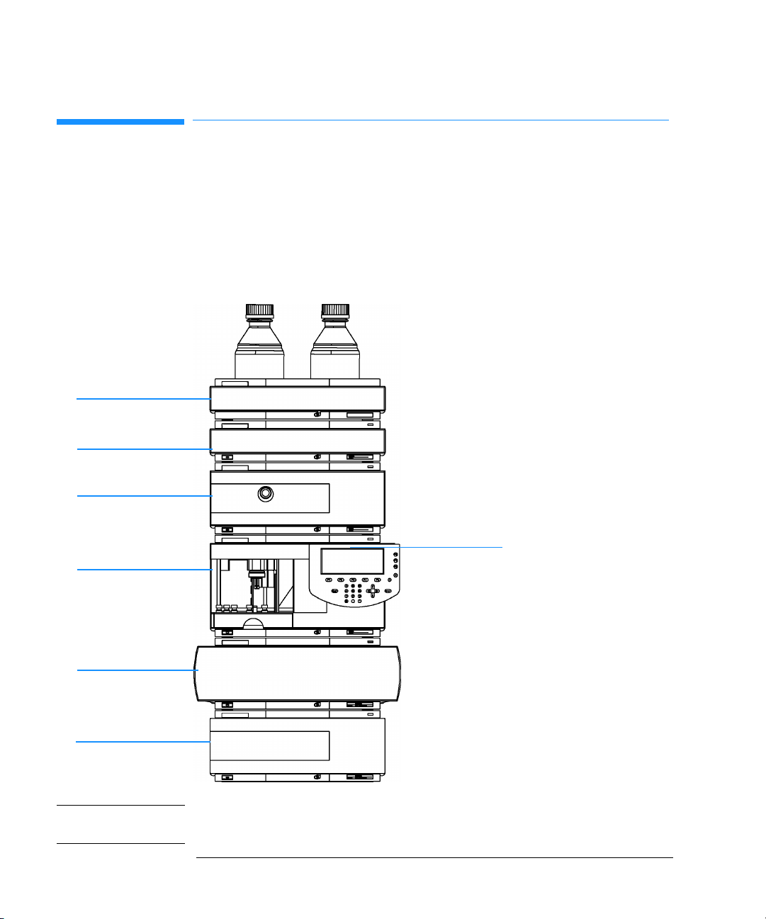
Figure 1 Recommended Stack Configuration (Front View)
Flow connections in the stack:
Example setup with 0.17mm ID green capillaries
Solvent bottles - degasser:
Solvent
cabinet
Vacuum
degasser
Quaternary pump
G1311-60003 (bottle-head assembly, PTFE-tubings)
Degasser - pump:
G1322-67300 (PTFE-tubings)
Pump - autosampler:
G1312-67305 (SST, green)
Pump purge valve - waste:
5062-2461 (PTFE tubing wide bore, reorder pack)
Control Module
Autosampler
Column compartment
Detector
Autosampler - column compartment:
G1313-87305 (SST, green)
Column compartment - column:
G1316-87300 (SST, green)
Column - detector:
DAD G1315-87311 (SST, coated)
VWD 5062-8522 (PEEK)
Detector - waste:
DAD 0890-1713 (PTFE, wide bore)
VWD 5062-8535 (PEEK)
5062-2463 (corrugated waste tubing, reorder pack)
NOTE For a detailed view of the flow connections refer to the section “Flow
Connections” in chapter 1 of the reference manuals of the individual modules.
20
Page 21
Installing the Pump
Optimizing the Stack Configuration
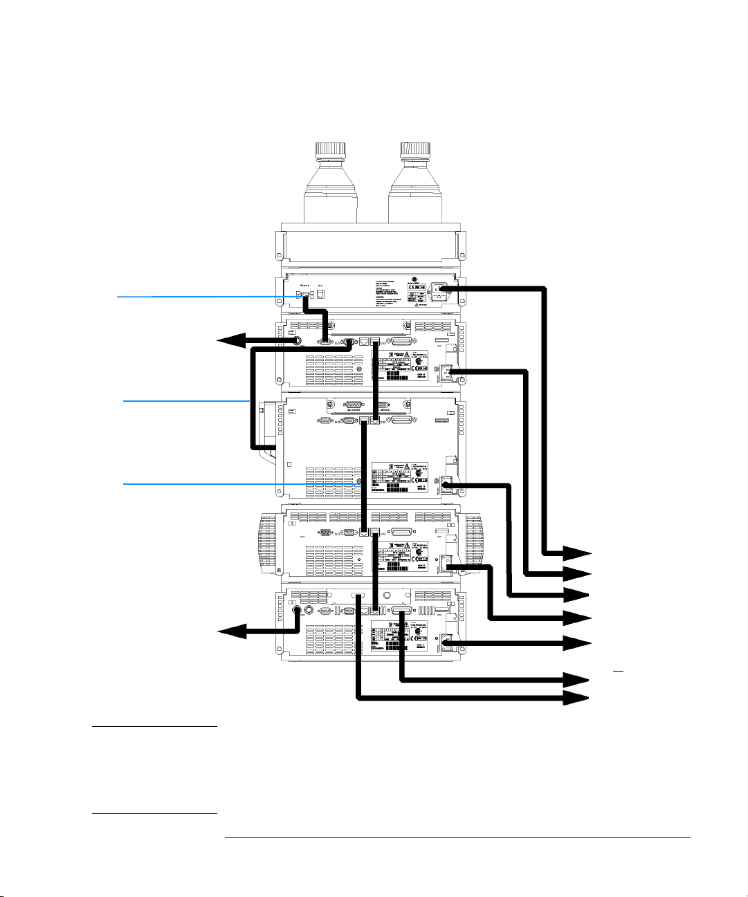
Figure 2 Recommended Stack Configuration (Rear View)
Remote cable
5061-3378
Pressure output to
recorder, for
PN see page 181
CAN Bus cable to
handheld controller
G1323-81600
CAN Bus cable for inter
module communication
5181-1516 (0.5m)
5161-1519 (1.0m)
AC power
Analog signal to
recorder,for
PN see page 181
GPIB or
LAN to ChemStation
for PN see page 181
NOTE If a single stack configuration becomes too high, e.g. if an additional module
like a G1327A ALS Thermostat is added or if your bench is to high, a two stack
configuration may be a better setup. Separate the stack between pump and
autosampler and place the stack containing the pump on the right side of the
stack containing the autosampler.
21
Page 22
Installing the Pump
S
Installing the Quaternary Pump
Installing the Quaternary Pump
Preparations Locate bench space.
Provide power connections.
Unpack the pump.
Parts required Pump
Power cord, for other cables see text below and “Cable Overview” on page 181
ChemStation and/or Control Module G1323A/B
1 Place the quaternary pump on the bench in a horizontal position.
2 Ensure the power switch on the front of the quaternary pump is OFF (switch
stands out).
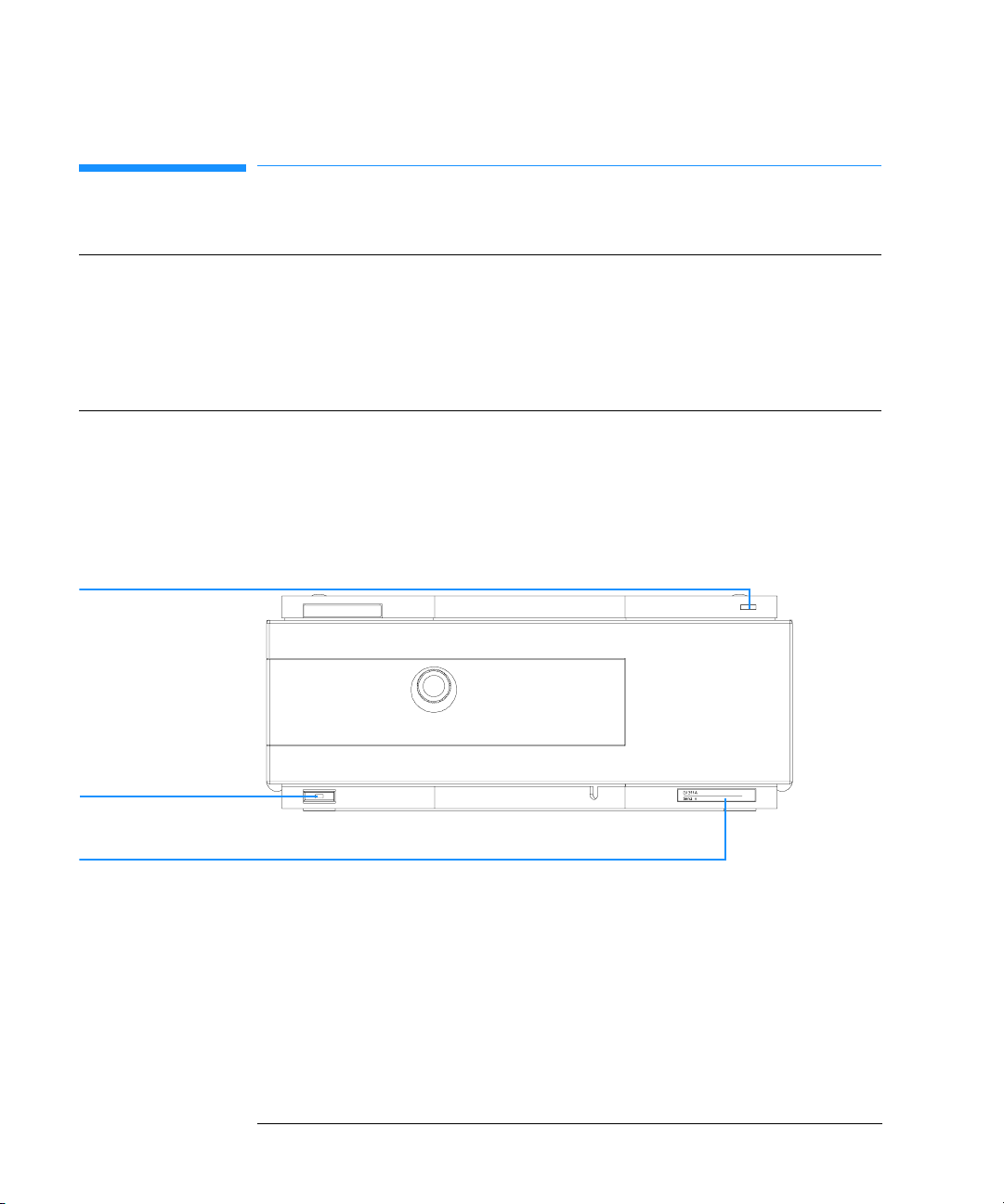
Figure 3 Front of Quaternary Pump
tatus Lamp
Power Switch
Serial number
3 At the rear of the quaternary pump move the security lever to its maximum
right position.
4 Connect the power cable to the power connector at the rear of the quaternary
pump. The security lever will prevent that the cover is opened while the power
cord is connected to the quaternary pump.
5 Connect the required interface cables to the quaternary pump.
22
Page 23
Installing the Pump
Installing the Quaternary Pump
NOTE In an Agilent 1100 Series system, the individual modules are connected
through CAN cables. The Agilent 1100 Series vacuum degasser is an exception
. The vacuum degasser can be connected via the APG remote connector to the
other modules of the stack. The AUX output allows the user to monitor the
vacuum level in the degasser chamber. An Agilent 1100 Series control module
can be connected to the CAN bus at any of the modules in the system except
for the degasser. The Agilent ChemStation can be connected to the system
through one GPIB or LAN (requires the installation of a LAN- board) cable at
any of the modules (except for the degasser), preferably at the detector
(MUST for the DAD). For more information about connecting the control
module or Agilent ChemStation refer to the respective user manual. For
connecting the Agilent 1100 Series equipment to non-Agilent 1100 Series
equipment, see Chapter 6 “Introduction to the Quaternary Pump”
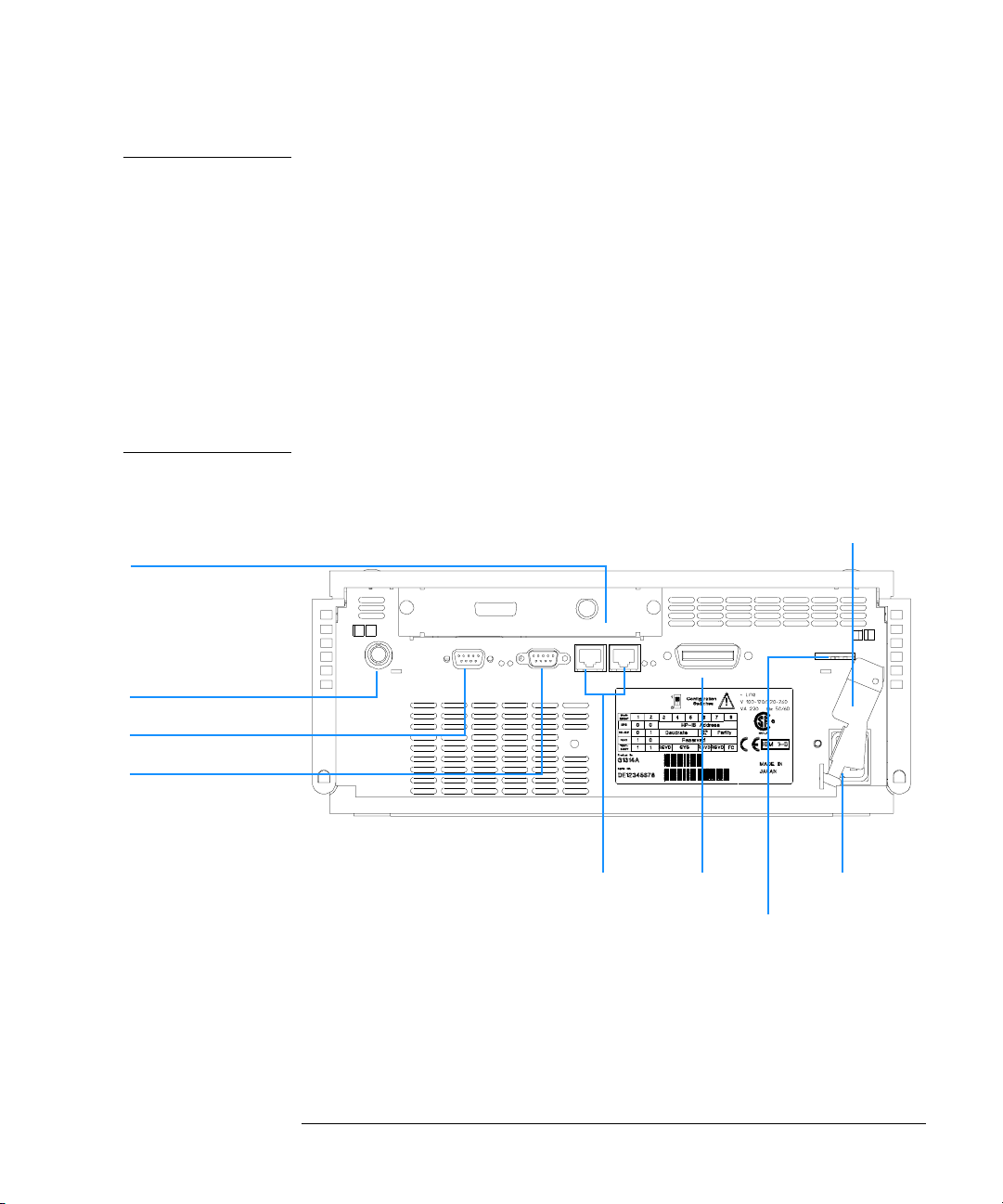
Figure 4 Rear of Quaternary Pump
Security lever
Slot for interface board
Analog pressure, 2mV/bar
APG Remote
RS-232C
CAN
GPIB Power
Configuration switch
6 Connect all capillaries, solvent tubes and waste tubing (see “Flow
Connections of the Quaternary Pump” on page 25).
7 Press in the power switch to turn on the quaternary pump.
23
Page 24

Installing the Pump
Installing the Quaternary Pump
NOTE The power switch stays pressed in and a green indicator lamp in the power
switch is on when the quaternary pump is turned on. When the line power
switch stands out and the green light is off, the quaternary pump is turned off.
8 Purge the quarternary pump (see “Priming and Purging the System” on page
28).
WARNING To disconnect the quaternary pump from line, unplug the power cord.
The power supply still uses some power, even if the power switch on
the front panel is turned off.
NOTE The pump was shipped with default configuration settings. To change these
settings, see “Setting the 8-bit Configuration Switch” on page 223.
24
Page 25

Installing the Pump
Flow Connections of the Quaternary Pump
Flow Connections of the Quaternary Pump
Preparations Pump is installed in the LC system.
Parts required Other modules
Parts from accessory kit, see “Accessory Kit Contents — Quaternary Pump” on page 18
Two wrenches 1/4–5/16 inch for capillary connections
WARNING When opening capillary or tube fittings solvents may leak out. Please
observe appropriate safety procedures (for example, goggles, safety
gloves and protective clothing) as described in the material handling
and safety data sheet supplied by the solvent vendor, especially when
toxic or hazardous solvents are used.
1 Remove the front cover by pressing the snap fasteners on both sides.
Figure 5 Removing the Front Cover
2 Place the vacuum degasser and the solvent cabinet on top of the quaternary
pump.
3 Put the bottle-head assemblies into solvent reservoirs containing your mobile
phase and place the bottle in the solvent cabinet.
4 Connect the inlet tubes from the bottle-head assemblies to the inlet
connectors A to D (typically the left connection of the channel) of the vacuum
degasser. Fix the tubes in the tube clips of the vacuum degasser.
25
Page 26

Installing the Pump
Flow Connections of the Quaternary Pump
5 Connect the solvent tubes to the outlet connectors (typically right connection
of the channel) of the vacuum degasser.
6 Connect the syringe adapter from the degasser accessory kit to the solvent
tube of channel A.
7 Using a piece of sanding paper connect the waste tubing to the purge valve
and place it into your waste system.
8 If the quaternary pump is not part of a Agilent1100 System stack or placed on
the bottom of a stack, connect the corrugated waste tube to the waste outlet
of the pump leak handling system.
9 Connect the pump outlet capillary (quaternary pump to injection device) to
the outlet of the purge valve.
10 Prime your system before first use (see “Priming and Purging the System” on
page 28).
26
Page 27
Installing the Pump
Flow Connections of the Quaternary Pump
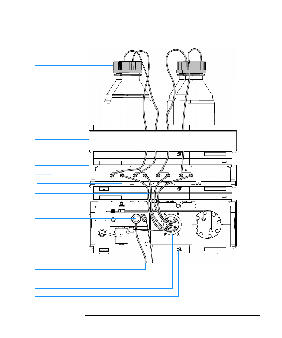
Figure 6 Flow Connections of the Quaternary Pump
Bottle-head assembly (G1311-60003)
Solvent cabinet
Vacuum degasser
Inlet
Outlet
Tube clip (1400-1578)
Tubings (G1322-67300)
Purge valve
Waste tubing (5062-2461)
Outlet capillary to autosampler (G1312-67305)
MCGV
Fitting for corrugated waste tubing (5062-2463, reorder pack, 5m)
27
Page 28

Installing the Pump
Priming and Purging the System
Priming and Purging the System
The system can be primed either by drawing solvent through the degasser
with a syringe or by pumping with the pump.
Priming the system with a syringe is recommended, when:
• vacuum degasser or connected tubings are used for the first time or
vacuum tubes are empty or
• changing to solvents that are immiscible with the solvent currently in the
vacuum tubes.
Priming the system by using the pump at high flow rate
(3–5 ml/min) is recommended, when:
• pumping system was turned off for a length of time (for example,
overnight) and if volatile solvent mixtures are used, or
• solvents have been changed.
WARNING When opening capillary or tube fittings solvents may leak out. Please
observe appropriate safety procedures (for example, goggles, safety
gloves and protective clothing) as described in the material handling
and safety data sheet supplied by the solvent vendor, especially when
toxic or hazardous solvents are used.
Priming with a Syringe
Before using a new degasser or new tubings for the first time:
1 Prime all tubings with at least 30 ml of iso-propanol no matter whether the
channels will be used with organic mobile phase or with water.
If you are changing to a solvent that is immiscible with the solvent currently
in the tubing continue as follows:
2 Replace the current solvent with adequate organic solvent (see Table 5 on
page 30), if current solvent is organic or with water, if current solvent is an
inorganic buffer or contains salt.
3 Disconnect solvent outlet tube of the channel that is supposed to be primed
from your pump.
4 Connect syringe adapter to solvent outlet tube.
28
Page 29

Installing the Pump
Priming and Purging the System
5 Push syringe adapter onto syringe.
6 Pull syringe plunger to draw at least 30 ml of solvent through degasser and
tubing.
7 Replace the priming solvent with the new solvent of your choice.
8 Pull syringe plunger to draw at least 30 ml of solvent through degasser and
tubing.
9 Disconnect syringe adapter from solvent tube.
10 Connect the solvent tube to the appropriate channel of the MCGV.
11 Repeat step 3 to step 10 for the other solvent channels.
NOTE When priming the vacuum degasser with a syringe the solvent is drawn
through the degasser tubes very quickly. The solvent at the degasser outlet will
therefore not be fully degassed. Pump for approximately 10 minutes with your
selected flow rate before starting any application. This will allow the vacuum
degasser to properly degas the solvent in the degasser tubes.
NOTE The pump should never be used for priming empty tubings (never let the pump
run dry). Use the syringe to draw enough solvent for completely filling the
tubings to the pump inlet before continueing to prime with the pump.
Priming with the Pump
When the pumping system has been turned off for a certain time (for
example, overnight) oxygen will rediffuse into the solvent channels between
the vacuum degasser and the pump. Solvents containing volatile ingredients
will slightly lose these, if left in the degasser without flow for a prolonged
period of time. Therefore priming of the vacuum degasser and the pumping
system is required before starting an application.
1 Open the purge valve of your pump (by turning it counterclockwise) and set
flow rate to 3-5 ml/min.
2 Flush the vacuum degasser and all tubes with at least 30 ml of solvent.
3 Set flow to required value of your application and close the purge valve.
4 Pump for approximately 10 minutes before starting your application.
5 Repeat step 1 to step 4 for other solvent channels, where needed.
29
Page 30

Installing the Pump
Priming and Purging the System
Table 5 Choice of Priming Solvents for Different Purposes
Activity Solvent Comments
After an installation
When switching between
reverse phase and normal
phase (both times)
After an installation Ethanol or Methanol Alternative to Isopropanol
To clean the system when
using buffers
After a solvent change
After the installation of
normal phase seals (P/N
0905-1420)
Isopropanol
Isopropanol
Bidistilled water
Bidistilled water
Hexane + 5% Isopropanol Good wetting properties
Best solvent to flush air out of
the system
Best solvent to flush air out of
the system
(second choice) if no
Isopropanol is available
Best solvent to re-dissolve
buffer cristals
Best solvent to re-dissolve
buffer cristals
30
Page 31

2
2 Optimizing Performance
How to optimize the quaternary pump to achieve
best chromatographic results
Page 32

Optimizing Performance
Hints for Successful Use of the Quaternary Pump
Hints for Successful Use of the Quaternary
Pump
• Always place the solvent cabinet with the solvent bottles on top of the
quaternary pump (or at a higher level).
• When using salt solutions and organic solvents in the Agilent 1100
Quaternary Pump it is recommended to connect the salt solution to one of
the bottom gradient valve ports and the organic solvent to one of the upper
gradient valve ports. It is best to have the organic channel directly above
the salt solution channel. Regular flushing with water of all MCGV
channels is recommended to remove all possible salt deposits in the valve
ports.
• Before operating the quaternary pump flush the vacuum degasser with at
least two volumes (30 ml), especially when turned off for a certain length
of time (for example, during the night) and volatile solvent mixtures are
used in the channels (see “Priming and Purging the System” on page 28).
• Prevent blocking of solvent inlet filters (never use the pump without
solvent inlet filter). Growth of algae should be avoided (see “Prevent
Blocking of Solvent Filters” on page 35).
• Check purge valve frit and column frit in regular time intervals. A blocked
purge valve frit can be identified by black or yellow layers on its surface or
by a pressure greater than 10 bar, when pumping distilled water at a rate
of 5 ml/min with an open purge valve.
• When using the quaternary pump at low flow rates (for example,
0.2 ml/min) check all 1/16-inch fittings for any signs of leaks.
• Whenever exchanging the pump seals the purge valve frit should be
exchanged, too.
• When using buffer solutions, flush the system with water before switching
it off. The seal wash option should be used when buffer concentrations of
0.1 Molar or higher will be used for long time periods.
• Check the pump plungers for scratches when changing the plunger seals.
Scratched plungers will lead to micro leaks and will decrease the lifetime
of the seal.
• Pressurize the system according to the wear in procedure after changing
the plunger seals (see “Exchanging the Pump Seals and Seal Wear-in
32
Page 33

Optimizing Performance
Hints for Successful Use of the Quaternary Pump
Procedure” on page 112).
33
Page 34

Optimizing Performance
Solvent Information
Solvent Information
Always filter solvents through 0.4 µm filters, small particles can permanently
block the capillaries and valves. Avoid the use of the following
steel-corrosive solvents:
• Solutions of alkali halides and their respective acids (for example, lithium
iodide, potassium chloride, and so on).
• High concentrations of inorganic acids like sulfuric acid, especially at
higher temperatures (replace, if your chromatography method allows, by
phosphoric acid or phosphate buffer which are less corrosive against
stainless steel).
• Halogenated solvents or mixtures which form radicals and/or acids, for
example:
+ O
3
→ 2COCl
2
2CHCl
This reaction, in which stainless steel probably acts as a catalyst, occurs
quickly with dried chloroform if the drying process removes the
stabilizing alcohol.
+ 2HCl
2
• Chromatographic grade ethers, which can contain peroxides (for example,
THF, dioxane, di-isopropylether) such ethers should be filtered through
dry aluminium oxide which adsorbs the peroxides.
• Mixtures of carbon tetrachloride with 2-propanol or THF dissolve stainless
steel.
34
Page 35

Optimizing Performance
Prevent Blocking of Solvent Filters
Prevent Blocking of Solvent Filters
Contaminated solvents or algae growth in the solvent bottle will reduce the
lifetime of the solvent filter and will influence the performance of the pump.
This is especially true for aqueous solvents or phosphate buffers (pH 4 to 7).
The following suggestions will prolong lifetime of the solvent filter and will
maintain the performance of the pump:
• Use sterile, if possible amber, solvent bottles to slow down algae growth.
• Filter solvents through filters or membranes that remove algae.
• Exchange solvents every two days or refilter.
• If the application permits add 0.0001–0.001 M sodium azide to the solvent.
• Place a layer of argon on top of your solvent.
• Avoid exposure of the solvent bottles to direct sunlight.
Checking the Solvent Filters
The solvent filters are on the low-pressure side of the pumping system. A
blocked filter therefore does not affect the pressure readings of the pump.
The pressure readings cannot be used to identify blocked filters. If the
solvent cabinet is placed on top of the vacuum degasser the filter condition
can be checked in the following way:
Remove the tubing at the inlet port of the vacuum degasser. If the filter is in
good condition the solvent will freely drip out of the solvent tube (due to
hydrostatic pressure). If the solvent filter is partly blocked no solvent or only
very little solvent will drip out of the solvent tube.
Cleaning the Solvent Filters
• Remove the blocked solvent filter from the bottle-head assembly and place
it in a beaker with concentrated nitric acid (35%) for one hour.
• Thoroughly flush the filter with bidistilled water (remove all nitric acid,
some capillary columns can be damaged by nitric acid).
• Replace the filter.
NOTE Never use the system without solvent filter installed.
35
Page 36

Optimizing Performance
Operational Hints for the Vacuum Degasser
Operational Hints for the Vacuum Degasser
Operational Hints for the Vacuum Degasser
If you are using the vacuum degasser for the first time, if the vacuum
degasser was switched off for any length of time (for example, overnight), or
if the vacuum degasser lines are empty, you should prime the vacuum
degasser before running an analysis.
The vacuum degasser can be primed either by drawing solvent through the
degasser with a syringe or by pumping with the quaternary pump.
Priming the degasser with a syringe is recommended, when:
• vacuum degasser is used for the first time, or vacuum tubes are empty, or
• changing to solvents that are immiscible with the solvent currently in the
vacuum tubes.
Priming the vacuum degasser by using the quaternary pump at high flow rate
is recommended, when:
• quaternary pump was turned off for a length of time (for example, during
night) and volatile solvent mixtures are used, or
• solvents have been changed.
For more information see the Reference Manual for the Agilent 1100 Series
vacuum degasser.
36
Page 37

Optimizing Performance
Operational Hints for the Multi Channel Gradient Valve (MCGV)
Operational Hints for the Multi Channel
Gradient Valve (MCGV)
In a mixture of salt solutions and organic solvent the salt solution might be
well dissolved in the organic solvent without showing precipitations.
However in the mixing point of the gradient valve, at the boundary between
the two solvents, micro precipitation is possible. Gravity forces the salt
particles to fall down. Normally the A channel of the valve is used for the
aqueous/salt solution and the B channel of the pump is used for the organic
solvent. If used in this configuration the salt will fall back into the salt
solution and will be dissolved. When using the pump in a different
configuration (e.g., D - salt solution, A -organic solvent) the salt can fall into
the port of the organic solvent and may lead to performance problems.
NOTE When using salt solutions and organic solvents in the Agilent 1100 Quaternary
Pump it is recommended to connect the salt solution to one of the bottom
ports and the organic solvent to one of the upper gradient valve ports. It is best
to have the organic channel directly above the salt solution channel.
Regular flushing with water of all MCGV channels is recommended to remove
all possible salt deposits in the valve ports.
37
Page 38

Optimizing Performance
When to use the Continuous Seal Wash Option
When to use the Continuous Seal Wash
Option
Highly-concentrated buffer solutions will reduce the lifetime of the seals and
plungers in your quaternary pump. The seal wash option allows to maintain
the seal lifetime by flushing the back side of the seal with a wash solvent.
The continuous seal wash option is strongly recommended when buffer
concentrations of 0.1 Molar or higher will be used for long time periods in the
quaternary pump.
The continuous seal wash option can be ordered by quoting part number
01018-68722 (kit contains parts for one pump head).
The seal wash option comprises a support ring, secondary seal, gasket and
seal keeper for both plunger sides. A wash bottle filled with water
/isopropanol (90/10) should be placed above the quaternary pump in the
solvent cabinet and gravity will maintain a flow through the pump head
removing all possible buffer crystals from the back of the pump seal.
NOTE Running dry is the worst case for a seal and drastically reduces its
lifetime.
The seal will build up sticky layers on the surface of the plunger. These sticky
layers will also reduce the lifetime of the primary seal. Therefore the tubes of
the wash option should always be filled with solvent to prolong the lifetime of
the wash seal. Always use a mixture of bidistilled water (90%) and isopropanol
(10%) as wash solvent. This mixture prevents bacteria growth in the wash
bottle and reduces the surface tension of the water. The flow rate should be
regulated to approximately 20 drops/minute. This can be done with the
velocity regulator supplied with the accessory kit.
For information on the installation of the continuous seal wash option refer
to “Installing the Continuous Seal Wash Option” on page 116.
38
Page 39

Optimizing Performance
When to Use Alternative Seals
When to Use Alternative Seals
The standard seal for the quaternary pump can be used for most applications.
However applications that use normal phase solvents (for example, hexane)
are not suited for the standard seal and require a different seal when used for
a longer time in the quaternary pump.
For applications that use normal phase solvents (for example, hexane) we
recommend the use of the polyethylene seals, part number 0905-1420 (pack
of 2). These seals have less abrasion compared to the standard seals.
NOTE Polyethylene seals have a limited pressure range 0–200 bar. When used above
200 bar their lifetime will be significantly reduced. DO NOT apply the seal
wear-in procedure performed with new standard seals at 400 bar.
39
Page 40

Optimizing Performance
Optimize the Compressibility Compensation Setting
Optimize the Compressibility
Compensation Setting
The compressibility compensation default setting is 100 × 10-6/bar for the
quaternary pump. This setting represents an average value. Under normal
conditions the default setting reduces the pressure pulsation to values
(below 1% of system pressure) that will be sufficient for most applications
and for all gradient analyses. For applications using sensitive detectors, the
compressibility settings can be optimized by using the values for the various
solvents described in Table 6. If the solvent in use is not listed in the
compressibility tables, when using isocratic mixtures of solvents and if the
default settings are not sufficient for your application the following
procedure can be used to optimize the compressibility settings.
NOTE When using mixtures of solvents it is not possible to calculate the
compressibility of the mixture by interpolating the compressibility values of
the pure solvents used in that mixture or by applying any other calculation. In
these cases the following empirical procedure has to be applied to optimize
your compressibility setting.
1 Start the quaternary pump with the required flow rate.
2 Before starting the optimization procedure, the flow must be stable. Use
degassed solvent only. Check the tightness of the system with the pressure
test (see “Pressure Test” on page 82).
3 Your pump must be connected to a Chemstation or a handheld controller, the
pressure and %-ripple can be monitored with one of these instruments,
otherwhise connect a signal cable between the pressure output of the
quaternary pump and a recording device (for example, 339X integrator) and
set parameters.
Zero 50%
Att 2^3
Chart Speed 10 cm/min
4 Start the recording device with the plot mode.
40
Page 41

Optimizing Performance
Optimize the Compressibility Compensation Setting
5 Starting with a compressibility setting of 10 × 10-6/bar increase the value in
steps of 10. Re-zero the integrator as required. The compressibility
compensation setting that generates the smallest pressure ripple is the
optimum value for your solvent composition.
Table 6 Solvent Compressibility
Solvent (pure) Compressibility (10
Acetone 126
Acetonitrile 115
Benzene 95
Carbon tetrachloride 110
Chloroform 100
Cyclohexane 118
Ethanol 114
Ethyl acetate 104
Heptane 120
Hexane 150
Isobutanol 100
Isopropanol 100
Methanol 120
1-Propanol 100
Toluene 87
-6
/bar)
Water 46
41
Page 42

Optimizing Performance
Optimize the Compressibility Compensation Setting
42
Page 43

3
3 Troubleshooting and
Test Functions
The quaternary pump’s built-in troubleshooting and
test functions
Page 44

Troubleshooting and Test
Functions
This chapter describes the instrument’s built in troubleshooting and test
functions.
Status Indicators
The quaternary pump is provided with two status indicators which indicate
the operational state (prerun, run, and error states) of the quaternary pump.
The status indicators provide a quick visual check of the operation of the
quaternary pump (see “Status Indicators” on page 45).
Error Messages
In the event of an electronic, mechanical or hydraulic failure, the quaternary
pump generates an error message in the user interface. The following pages
describe the meaning of the error messages. For each message, a short
description of the failure, a list of probable causes of the problem, and a list
of suggested actions to fix the problem are provided (see “Error Messages”
on page 47).
Pressure Test
The pressure test is a quick test designed to determine the pressure tightness
of the system. After exchanging flow path components (e.g. pump seals or
injection seal), use this test to verify the system is pressure tight up to 400 bar
(see “Pressure Test” on page 82).
Leak Test
The leak test is a diagnostic test designed to determine the pressure tightness
of the quaternary pump. When a problem with the quaternary pump is
suspected, use this test to help troubleshoot the quaternary pump and its
pumping performance. The following sections describe these functions in
detail (see “Leak Test” on page 88).
44
Page 45

Troubleshooting and Test Functions
Status Indicators
Two status indicators are located on the front of the quaternary pump. The
lower left one indicates the power supply status, the upper right one
indicates the quaternary pump status.
Figure 7 Location of Status Indicators
Status indicator
Power supply indicator
45
Page 46

Power Supply Indicator
The power supply indicator is integrated into the main power switch. When
the indicator is illuminated (green) the power is ON.
When the indicator is off, the module is turned OFF. Otherwhise check power
connections, availability of power or check functioning of the power supply.
Pump Status Indicator
The Pump status indicator indicates one of four possible instrument
conditions:
• When the status indicator is OFF (and power switch light is on), the
quaternary pump is in a prerun condition, and is ready to begin an analysis.
• A green status indicator, indicates the quaternary pump is performing an
analysis (run mode).
• A yellow indicator indicates a not-ready condition. The quaternary pump
is in a not-ready state when it is waiting for a specific condition to be
reached or completed (for example, immediately after changing a
setpoint), or while a self-test procedure is running.
• An error condition is indicated when the status indicator is red. An error
condition indicates the quaternary pump has detected an internal problem
which affects correct operation of the quaternary pump. Usually, an error
condition requires attention (for example, leak, defective internal
components). An error condition always interrupts the analysis.
• A flashing yellow status indicator indicates that the module is in its
resident mode. Call your local service provider for assistance upon
observing this error condition.
• A flashing red status indicator indicates a severe error during the startup
procedure of the module. Call your local service provider for assistance
upon observing this error condition.
46
Page 47

Troubleshooting and Test Functions
Error Messages
Error Messages
Error messages are displayed in the user interface when an electronic,
mechanical, or hydraulic (flow path) failure occurs which requires attention
before the analysis can be continued (for example, repair, frit exchange or
exchange of consumables required). In the event of such a failure, the red
status indicator at the front of the quaternary pump is switched on, and an
entry is written into the instrument logbook.
47
Page 48

Time out
The timeout threshold was exceeded.
Probable Causes • The analysis was completed successfully, and the timeout function
switched off the quaternary pump as requested.
• A not-ready condition was present during a sequence or multiple-injection
run for a period longer than the timeout threshold.
Suggested Actions ❏ Check the logbook for the occurrence and source of a not-ready condition.
Restart the analysis where required.
48
Page 49

Troubleshooting and Test Functions
Shut-Down
Shut-Down
An external instrument has generated a shut-down signal on the remote line.
The quaternary pump continually monitors the remote input connectors for
status signals. A LOW signal input on pin 4 of the remote connector generates
the error message.
Probable Causes • Leak detected in another module with a CAN connection to the system .
• Leak detected in an external instrument with a remote connection to the
system.
• Shut-down in an external instrument with a remote connection to the
system.
• The degasser failed to generate sufficient vacuum for solvent degassing.
Suggested Actions ❏ Fix the leak in the external instrument before restarting the quaternary
pump.
❏ Check external instruments for a shut-down condition.
❏ Check the vacuum degasser for an error condition. Refer to the Reference
Manual for the Agilent 1100 Series vacuum degasser.
49
Page 50

Troubleshooting and Test Functions
Remote Timeout
Remote Timeout
A not-ready condition is still present on the remote input .
When an analysis is started, the system expects all not-ready conditions (e.g.
a not-ready condition during detector balance) to switch to run conditions
within one minute of starting the analysis. If a not-ready condition is still
present on the remote line after one minute the error message is generated.
Probable Causes • Not-ready condition in one of the instruments connected to the remote
line.
• Defective remote cable.
• Defective components in the instrument showing the not-ready condition.
Suggested Actions ❏ Ensure the instrument showing the not-ready condition is installed
correctly, and is set up correctly for analysis.
❏ Exchange the remote cable.
❏ Check the instrument for defects (refer to the instrument’s reference
documentation).
50
Page 51

Troubleshooting and Test Functions
Synchronization Lost
Synchronization Lost
During an analysis, the internal synchronization or communication between
one or more of the modules in the system has failed.
The system processors continually monitor the system configuration. If one
or more of the modules is no longer recognized as being connected to the
system, the error message is generated.
Probable Causes • CAN cable disconnected.
• Defective CAN cable.
• Defective main board in another module.
Suggested Actions ❏ Ensure all the CAN cables are connected correctly.
❏ Switch off the system. Restart the system, and determine which module or
modules are not recognized by the system.
❏ Ensure all CAN cables are installed correctly.
51
Page 52

Troubleshooting and Test Functions
Leak
Leak
A leak was detected in the quaternary pump.
The signals from the two temperature sensors (leak sensor and
board-mounted temperature-compensation sensor) are used by the leak
algorithm to determine whether a leak is present. When a leak occurs, the
leak sensor is cooled by the solvent. This changes the resistance of the leak
sensor which is sensed by the leak-sensor circuit on the LPM board
Probable Causes • Loose fittings.
• Broken capillary.
• Loose or leaking purge valve, active inlet valve, or outlet ball valve.
• Defective pump seals.
Suggested Actions ❏ Ensure all fittings are tight.
❏ Exchange defective capillaries.
❏ Ensure pump components are seated correctly. If there are still signs of a
leak, exchange the appropriate seal (purge valve, active inlet valve, outlet
ball valve).
❏ Exchange the pump seals.
52
Page 53

Troubleshooting and Test Functions
Leak Sensor Open
Leak Sensor Open
The leak sensor in the quaternary pump has failed (open circuit).
The current through the leak sensor is dependent on temperature. A leak is
detected when solvent cools the leak sensor, causing the leak-sensor current
to change within defined limits. If the current falls outside the lower limit, the
error message is generated.
Probable Causes • Leak sensor not connected to the LPM board.
• Defective leak sensor.
• Leak sensor incorrectly routed, being pinched by a metal component.
Suggested Actions ❏ Ensure the leak sensor is connected correctly.
❏ Exchange the leak sensor.
53
Page 54

Troubleshooting and Test Functions
Leak Sensor Short
Leak Sensor Short
The leak sensor in the quaternary pump has failed (short circuit).
The current through the leak sensor is dependent on temperature. A leak is
detected when solvent cools the leak sensor, causing the leak-sensor current
to change within defined limits. If the current increases above the upper
limit, the error message is generated.
Probable Causes • Defective leak sensor.
• Leak sensor incorrectly routed, being pinched by a metal component.
Suggested Actions ❏ Exchange the leak sensor.
54
Page 55

Troubleshooting and Test Functions
Compensation Sensor Open
Compensation Sensor Open
The ambient-compensation sensor (NTC) on the LPM board in the quaternary
pump has failed (open circuit).
The resistance across the temperature compensation sensor (NTC) on the
LPM board is dependent on ambient temperature. The change in resistance is
used by the leak circuit to compensate for ambient temperature changes. If
the resistance across the sensor increases above the upper limit, the error
message is generated.
Probable Causes • Defective LPM board.
Suggested Actions ❏ Exchange the LPM board.
55
Page 56

Troubleshooting and Test Functions
Compensation Sensor Short
Compensation Sensor Short
The ambient-compensation sensor (NTC) on the LPM board in the quaternary
pump has failed (short circuit).
The resistance across the temperature compensation sensor (NTC) on the
LPM board is dependent on ambient temperature. The change in resistance is
used by the leak circuit to compensate for ambient temperature changes. If
the resistance across the sensor falls below the lower limit, the error message
is generated.
Probable Causes • Defective LPM board.
Suggested Actions ❏ Exchange the LPM board.
56
Page 57

Troubleshooting and Test Functions
Fan Failed
Fan Failed
The cooling fan in the quaternary pump has failed.
The hall sensor on the fan shaft is used by the LPM board to monitor the fan
speed. If the fan speed falls below 2 revolutions/second for longer than
5 seconds, the error message is generated.
Probable Causes • Fan cable disconnected.
• Defective fan.
• Defective LPM board.
• Improperly positioned cables or wires obstructing fan blades.
Suggested Actions ❏ Ensure the fan is connected correctly.
❏ Exchange fan.
❏ Exchange the LPM board.
❏ Ensure the fan is not mechanically blocked.
57
Page 58

Troubleshooting and Test Functions
Open Cover
Open Cover
The top foam has been removed.
The sensor on the LPM board detects when the top foam is in place. If the
foam is removed, the fan is switched off, and the error message is generated.
Probable Causes • The top foam was removed during operation.
• Foam not activating the sensor.
• Sensor defective.
• Rear of the module is exposed to strong direct sunlight.
Suggested Actions ❏ Replace the top foam.
❏ Exchange the LPM board.
❏ Ensure that the rear of module is not directly exposed to strong sunlight.
58
Page 59

Troubleshooting and Test Functions
Restart Without Cover
Restart Without Cover
The quaternary pump was restarted with the top cover and foam open.
The sensor on the LPM board detects when the top foam is in place. If the
quaternary pump is restarted with the foam removed, the quaternary pump
switches off within 30 s, and the error message is generated.
Probable Causes • The quaternary pump started with the top cover and foam removed.
• Rear of the module is exposed to strong direct sunlight.
Suggested Actions ❏ Replace the top cover and foam.
❏ Ensure that the rear of module is not directly exposed to strong sunlight.
59
Page 60

Troubleshooting and Test Functions
Zero Solvent Counter
Zero Solvent Counter
Pump firmware version A.02.32 and higher allow to set solvent bottle fillings
at the ChemStation (revision 5.xx and higher). If the volume level in the
bottle falls below the specified value the error message appears when the
feature is configured accordingly.
Probable Causes • Volume in bottle below specified volume.
• Incorrect setting of limit.
Suggested Actions ❏ Refill bottles and reset solvent counters.
60
Page 61

Troubleshooting and Test Functions
Pressure Above Upper Limit
Pressure Above Upper Limit
The system pressure has exceeded the upper pressure limit.
Probable Causes • Upper pressure limit set too low.
• Blockage in the flowpath (after the damper).
• Defective damper.
• Defective LPM board.
Suggested Actions ❏ Ensure the upper pressure limit is set to a value suitable for the analysis.
❏ Check for blockage in the flowpath. The following components are
particularly subject to blockage:
purge-valve frit.
needle (autosampler),
seat capillary (autosampler),
sample loop (autosampler), and
column frits.
capillaries with low internal diameters (e.g. 0.12mm id).
❏ Exchange the damper.
❏ Exchange the LPM board.
61
Page 62

Troubleshooting and Test Functions
Pressure Below Lower Limit
Pressure Below Lower Limit
The system pressure has fallen below the lower pressure limit.
Probable Causes • Lower pressure limit set too high.
• Air bubbles in the mobile phase.
• Leak.
• Defective damper.
• Defective LPM board.
Suggested Actions ❏ Ensure the lower pressure limit is set to a value suitable for the analysis.
❏ Ensure solvents are degassed. Purge the quaternary pump.
❏ Ensure solvent inlet filters are not blocked.
❏ Inspect the pump head, capillaries and fittings for signs of a leak.
❏ Purge the quaternary pump. Run a pressure test to determine whether the
seals or other pump components are defective.
❏ Exchange the damper.
❏ Exchange the LPM board.
62
Page 63

Troubleshooting and Test Functions
Pressure Signal Missing
Pressure Signal Missing
The pressure signal from the damper is missing.
The pressure signal from the damper must be within a specific voltage range.
If the pressure signal is missing, the processor detects a voltage of
approximately -120mV across the damper connector.
Probable Causes • Damper disconnected.
• Defective damper.
Suggested Actions ❏ Ensure the damper is connected correctly to the LPM board.
❏ Exchange the damper.
63
Page 64

Troubleshooting and Test Functions
Missing Pressure Reading
Missing Pressure Reading
The pressure readings read by the pump ADC (analog-digital converter) are
missing.
The ADC reads the pressure readings from the damper every 1ms. If the
readings are missing for longer than 10 seconds, the error message is
generated.
Probable Causes • Damper not connected.
• Defective damper.
• Defective LPM board.
Suggested Actions ❏ Ensure the damper is connected, clean and seated correctly.
❏ Exchange the damper.
❏ Exchange the LPM board.
64
Page 65

Troubleshooting and Test Functions
Pump Configuration
Pump Configuration
At switch-on, the quaternary pump has recognized a new pump
configuration.
The quaternary pump is assigned its configuration at the factory. If the
gradient valve is disconnected, and the quaternary pump is rebooted, the
error message is generated. However, the pump will function as an isocratic
pump in this configuration.The error message reappears after each
switch-on.
Probable Causes • Gradient valve disconnected.
Suggested Actions ❏ Reconnect the gradient valve.
65
Page 66

Troubleshooting and Test Functions
Valve Fuse
Valve Fus e
Valve Fuse 0 : Channels A and B
Valve Fuse 1 : Channels C and D
The gradient valve in the quaternary pump has drawn excessive current
causing the electronic fuse to open.
Probable Causes • Defective gradient valve.
• Defective connection cable (front panel to LPM board).
• Defective LPM board.
Suggested Actions ❏ Restart the quaternary pump. If the error message appears again, exchange
the gradient valve.
❏ Exchange the connection cable.
❏ Exchange the LPM board.
66
Page 67

Troubleshooting and Test Functions
Inlet-Valve Fuse
Inlet-Valve Fuse
The active-inlet valve in the quaternary pump has drawn excessive current
causing the inlet-valve electronic fuse to open.
Probable Causes • Defective active inlet valve.
• Defective connection cable (front panel to LPM board).
• Defective LPM board.
Suggested Actions ❏ Restart the quaternary pump. If the error message appears again, exchange
the active inlet valve.
❏ Exchange the connection cable.
❏ Exchange the LPM board.
67
Page 68

Troubleshooting and Test Functions
Valve Failed
Valve Failed
Valve 0 Failed: valve A
Valve 1 Failed: valve B
Valve 2 Failed: valve C
Valve 3 Failed: valve D
One of the valves of the multi-channel gradient valve has failed to switch
correctly.
The processor monitors the valve voltage before and after each switching
cycle. If the voltages are outside expected limits, the error message is
generated.
Probable Causes • Gradient valve disconnected.
• Connection cable (inside instrument) not connected.
• Connection cable (inside instrument) defective.
• Gradient valve defective.
Suggested Actions ❏ Ensure the gradient valve is connected correctly.
❏ Ensure the connection cable is connected correctly.
❏ Exchange the connection cable.
❏ Exchange the gradient valve.
68
Page 69

Troubleshooting and Test Functions
Motor-Drive Power
Motor-Drive Power
The current drawn by the pump motor exceeded the maximum limit.
Blockages in the flow path are usually detected by the pressure sensor in the
damper, which result in the pump switching off when the upper pressure
limit is exceeded. If a blockage occurs before the damper, the pressure
increase cannot be detected by the pressure sensor and the quaternary pump
will continue to pump. As pressure increases, the pump drive draws more
current. When the current reaches the maximum limit, the quaternary pump
is switched off, and the error message is generated.
Probable Causes • Flow path blockage in front of the damper.
• Blocked active inlet valve.
• Blocked outlet ball valve.
• High friction (partial mechanical blockage) in the pump drive assembly.
• Defective pump drive assembly.
• Defective LPM board.
Suggested Actions ❏ Ensure the capillaries and frits between the pump head and damper inlet
are free from blockage.
❏ Exchange the active inlet valve.
❏ Exchange the outlet ball valve.
❏ Remove the pump-head assembly. Ensure there is no mechanical blockage
of the pump-head assembly or pump drive assembly.
❏ Exchange the pump drive assembly.
❏ Exchange the LPM board.
69
Page 70

Troubleshooting and Test Functions
Encoder Missing
Encoder Missing
The optical encoder on the pump motor in the quaternary pump is missing or
defective.
The processor checks the presence of the pump encoder connector every
2 seconds. If the connector is not detected by the processor, the error
message is generated.
Probable Causes • Defective or disconnected pump encoder connector.
• Defective pump drive assembly.
Suggested Actions ❏ Ensure the connector is clean, and seated correctly.
❏ Exchange the pump drive assembly.
70
Page 71

Troubleshooting and Test Functions
Inlet-Valve Missing
Inlet-Valve Missing
The active-inlet valve in the quaternary pump is missing or defective.
The processor checks the presence of the active-inlet valve connector every
2 seconds. If the connector is not detected by the processor, the error
message is generated.
Probable Causes • Disconnected or defective cable.
• Disconnected or defective connection cable (front panel to LPM board).
• Defective active inlet valve.
Suggested Actions ❏ Ensure the pins of the active inlet valve connector are not damaged.
Ensure the connector is seated securely.
❏ Ensure the connection cable is seated correctly. Exchange the cable if
defective.
❏ Exchange the active inlet valve.
71
Page 72

Troubleshooting and Test Functions
Temperature Out of Range
Temperature Out of Range
The temperature sensor readings in the motor-drive circuit are out of range.
The values supplied to the ADC by the hybrid sensors must be between 0.5 V
and 4.3 V. If the values are outside this range, the error message is generated.
Probable Causes • Defective LPM board.
Suggested Actions ❏ Exchange the LPM board.
72
Page 73

Troubleshooting and Test Functions
Temperature Limit Exceeded
Temperature Limit Exceeded
The temperature of one of the motor-drive circuits is too high.
The processor continually monitors the temperature of the drive circuits on
the LPM board. If excessive current is being drawn for long periods, the
temperature of the circuits increases. If the temperature exceeds the upper
limit of 95 ºC, the error message is generated.
Probable Causes • High friction (partial mechanical blockage) in the pump drive assembly.
• Partial blockage of the flowpath in front of the damper.
• Defective pump drive assembly.
• Defective LPM board.
Suggested Actions ❏ Ensure the capillaries and frits between the pump head and damper inlet
are free from blockage.
❏ Ensure the outlet valve is not blocked.
❏ Remove the pump head assembly. Ensure there is no mechanical blockage
of the pump head assembly or pump drive assembly.
❏ Exchange the pump drive assembly.
❏ Exchange the LPM board.
73
Page 74

Troubleshooting and Test Functions
Servo Restart Failed
Servo Restart Failed
The pump motor in the quaternary pump was unable to move into the correct
position for restarting.
When the quaternary pump is switched on, the first step is to switch on the C
phase of the variable reluctance motor. The rotor should move to one of the
C positions. The C position is required for the servo to be able to take control
of the phase sequencing with the commutator. If the rotor is unable to move,
or if the C position cannot be reached, the error message is generated.
Probable Causes • Disconnected or defective cables.
• Blocked active inlet valve.
• Mechanical blockage of the quaternary pump.
• Defective pump drive assembly.
• Defective LPM board.
Suggested Actions ❏ Ensure the pump-assembly cables are not damaged or dirty. Make sure the
cables are connected securely to the LPM board.
❏ Exchange the active inlet valve.
❏ Remove the pump-head assembly. Ensure there is no mechanical blockage
of the pump-head assembly or pump drive assembly.
❏ Exchange the pump drive assembly.
❏ Exchange the LPM board.
74
Page 75

Troubleshooting and Test Functions
Pump Head Missing
Pump Head Missing
The pump-head end stop in the quaternary pump was not found.
When the quaternary pump restarts, the metering drive moves forward to the
mechanical end stop. Normally, the end stop is reached within 20 seconds,
indicated by an increase in motor current. If the end point is not found within
20 seconds, the error message is generated.
Probable Causes • Pump head not installed correctly (screws not secured, or pump head not
seated correctly).
• Broken plunger.
Suggested Actions ❏ Install the pump head correctly. Ensure nothing (e.g. capillary) is trapped
between the pump head and body.
❏ Exchange the plunger.
75
Page 76

Troubleshooting and Test Functions
Index Limit
Index Limit
The time required by the plunger to reach the encoder index position was too
short (quaternary pump).
During initialization, the first plunger is moved to the mechanical stop. After
reaching the mechanical stop, the plunger reverses direction until the
encoder index position is reached. If the index position is reached too fast,
the error message is generated.
Probable Causes • Irregular or sticking drive movement.
• Defective pump drive assembly.
Suggested Actions ❏ Remove the pump head, and examine the seals, plungers, and internal
components for signs of wear, contamination or damage. Exchange
components as required.
❏ Exchange the pump drive assembly.
76
Page 77

Troubleshooting and Test Functions
Index Adjustment
Index Adjustment
The encoder index position in the quaternary pump is out of adjustment.
During initialization, the first plunger is moved to the mechanical stop. After
reaching the mechanical stop, the plunger reverses direction until the
encoder index position is reached. If the time to reach the index position is
too long, the error message is generated.
Probable Causes • Irregular or sticking drive movement.
• Defective pump drive assembly.
Suggested Actions ❏ Remove the pump head, and examine the seals, plungers, and internal
components for signs of wear, contamination or damage. Exchange
components as required.
❏ Exchange the pump drive assembly.
77
Page 78

Troubleshooting and Test Functions
Index Missing
Index Missing
The encoder index position in the quaternary pump was not found during
initialization.
During initialization, the first plunger is moved to the mechanical stop. After
reaching the mechanical stop, the plunger reverses direction until the
encoder index position is reached. If the index position is not recognized
within a defined time, the error message is generated.
Probable Causes • Disconnected or defective encoder cable.
• Defective pump drive assembly.
Suggested Actions ❏ Ensure the encoder cable are not damaged or dirty. Make sure the cables
are connected securely to the LPM board.
❏ Exchange the pump drive assembly.
78
Page 79

Troubleshooting and Test Functions
Stroke Length
Stroke Length
The distance between the lower plunger position and the upper mechanical
stop is out of limits (quaternary pump).
During initialization, the quaternary pump monitors the drive current. If the
plunger reaches the upper mechanical stop position before expected, the
motor current increases as the quaternary pump attempts to drive the
plunger beyond the mechanical stop. This current increase causes the error
message to be generated.
Probable Causes • Defective pump drive assembly.
Suggested Actions ❏ Exchange the pump drive assembly.
79
Page 80

Troubleshooting and Test Functions
Initialization Failed
Initialization Failed
The quaternary pump failed to initialize successfully within the maximum
time window.
A maximum time is assigned for the complete pump-initialization cycle. If the
time is exceeded before initialization is complete, the error message is
generated.
Probable Causes • Blocked active inlet valve.
• Defective pump drive assembly.
• Defective LPM board.
Suggested Actions ❏ Exchange the active inlet valve.
❏ Exchange the pump drive assembly.
❏ Exchange the LPM board.
80
Page 81

Troubleshooting and Test Functions
Wait Timeout
Wait Timeout
When running certain tests in the diagnostics mode or other special
applications, the pump must wait for the plungers to reach a specific
position, or must wait for a certain pressure or flow to be reached. Each
action or state must be completed within the timeout period, otherwise the
error message is generated.
Possible Reasons for a
Wait Timeout
Probable Causes • Purge valve still open.
Suggested Actions ❏ Ensure that purge valve is closed.
• Pressure not reached.
• Pump channel A did not reach the delivery phase.
• Pump channel B did not reach the delivery phase.
• Pump channel A did not reach the take-in phase.
• Pump channel B did not reach the take-in phase.
• Solvent volume not delivered within the specified time.
• Leak at fittings, purge valve, active inlet valve, outlet ball valve or plunger
seals.
• Flow changed after starting test.
• Defective pump drive assembly.
❏ Exchange defective capillaries.
❏ Ensure pump components are seated correctly. If there are still signs of a
leak, exchange the appropriate seal (purge valve, active inlet valve, outlet
ball valve, plunger seal).
❏ Ensure correct operating condition for the special application in use.
❏ Exchange the defective pump drive assembly.
81
Page 82

Pressure Test
Description
The pressure test is a quick, built-in test designed to demonstrate the
pressure-tightness of the system. The test should be used when problems
with small leaks are suspected, or after maintenance of flow-path
components (e.g. pump seals, injection seal) to prove pressure tightness up
to 400 bar. The test involves monitoring the pressure profile as the pump runs
through a predefined pumping sequence. The resulting pressure profile
provides information about the pressure tightness of the system.
The column compartment outlet (or the outlet of the last module before the
detector) is blocked with a blank nut, and then the test is run using isopropyl
alcohol (IPA), while monitoring the pressure profile (using an integrator on
the analog output, or in the plot screen in the ChemStation). The pressure
profile is shown in Figure 8.
Figure 8 Typical Pressure-Test Pressure Profile with IPA
Pressure
Step 2
Step 1
Time [minutes]
Step 1 The test begins with the initialization of the pump. After initialization,
plunger 1 is at the top of its stroke. Next, the pump begins pumping solvent
82
Page 83

Troubleshooting and Test Functions
Pressure Test
with a flow rate of 510 µl/min and stroke of 100 µl. The pump continues to
pump until a system pressure of 390 bar is reached.
Step 2 When the system pressure reaches 390 bar, the pump switches off. The
pressure drop from this point onwards should be no more than 2 bar/minute.
Positioning the blank nut
To test the complete system’s pressure tightness, the blank nut should be
positioned at the column compartment outlet (or the outlet of the last
module before the detector).
If a specific component is suspected of causing a system leak, place the blank
nut immediately before the suspected component, then run the pressure test
again. If the test passes, the defective component is located after the blank
nut. Confirm the diagnosis by placing the blank nut immediately after the
suspected component. The diagnosis is confirmed if the test fails.
83
Page 84

Troubleshooting and Test Functions
Running the Pressure Test
Running the Pressure Test
Tools required
Parts and materials
required
¼-inch” wrench
Blank nut, 01080-83202
Isopropanol, 500 ml
Running the test from the ChemStation
1 Select the pressure test from the test selection box in the Diagnosis screen.
2 Start the test and follow the instructions.
NOTE Make absolutely sure that all parts of the flow path that are part of the
test are very thoroughly flushed with IPA before starting to pressurize
the system! Any trace of other solvents or the smallest air bubble
inside the flow path definitely will cause the test to fail!
The slope and plateau are evaluated automatically. “Evaluating the Results”
on page 86 describes the evaluation and interpretation of the pressure test
results.
Running the test from the Control Module
1 Place a bottle of LC-grade isopropyl alcohol in channel D.
2 Block column compartment outlet (or the outlet of the last module before the
detector) with a blank nut (01080-83202), See “Positioning the blank nut” on
page 83.
3 Open the purge valve. Set flow for channel D to 5 ml/min and flush the
degasser for about 10 minutes.
4 Set flow to 0 ml/min. Leave the purge valve open.
5 Connect the signal cable to the analog output at the rear of the pump module
(only if an integrator is used).
6 Press Execute to initialize the pressure test.
84
Page 85

Troubleshooting and Test Functions
Running the Pressure Test
Once the test is started, the pump moves the plungers into the start position.
When the plungers are in position, the user interface prompts you to close
the purge valve, and continue the test.
7 Close the purge valve, select continue on the control module and press Enter
to start the test.
The control module displays a graphical representation of the pressure.
“Evaluating the Results” on page 86 describes the evaluation and
interpretation of the pressure test results.
8 When the test is finished slowly open the purge valve to release the pressure
in the system.
85
Page 86

Troubleshooting and Test Functions
Evaluating the Results
Evaluating the Results
The sum of all leaks between the pump and the blank nut will be indicated by
a pressure drop of >2 bar/minute at the plateau. Note that small leaks may
cause the test to fail, but solvent may not be seen leaking from a module.
NOTE Please notice the difference between an error in the test and a failure of the
test! An error means that during the operation of the test there was an
abnormal termination. If a test failed, this means that the results of the test
where not within the specified limits.
If the pressure test fails:
• Ensure all fittings between the pump and the blank nut are tight. Repeat
the pressure test.
NOTE Often it is only a damaged blank nut itself (poorly shaped from overtightening)
that causes a failure of the test. Before investigating on any other possible
sources of failure make sure that the blank nut you are using is in good
condition and properly tightened!
• If the test fails again, insert the blank nut at the outlet of the previous
module in the stack (eg. autosampler, port 6 of the injection valve), and
repeat the pressure test. Exclude each module one by one to determine
which module is leaking.
• If the pump is determined to be the source of the leak, run the leak test.
86
Page 87

Troubleshooting and Test Functions
Evaluating the Results
Potential Causes of Pressure Test Failure
After isolating and fixing the cause of the leak, repeat the pressure test to
confirm the system is pressure tight.
Potential Cause (Pump) Corrective Action
Purge valve open. Close the purge valve.
Loose or leaky fitting. Tighten the fitting or exchange the capillary.
Damaged pump seals or plungers. Run the leak test to confirm the leak.
Loose purge valve. Tighten the purge valve nut (14 mm wrench).
Potential Cause (Autosampler) Corrective Action
Loose or leaky fitting. Tighten or exchange the fitting or capillary.
Rotor seal (injection valve). Exchange the rotor seal.
Damaged metering seal or plunger. Exchange the metering seal. Check the
plunger for scratches. Exchange the plunger if
required.
Needle seat. Exchange the needle seat.
Potential Cause (Column Compartment) Corrective Action
Loose or leaky fitting. Tighten or exchange the fitting or capillary.
Rotor seal (column switching valve). Exchange the rotor seal.
87
Page 88

Troubleshooting and Test Functions
Leak Test
Leak Test
Description
The leak test is a built-in troubleshooting test designed to demonstrate the
leak-tightness of the pump. The test should be used when problems with the
pump are suspected. The test involves monitoring the pressure profile as the
pump runs through a predefined pumping sequence. The resulting pressure
profile provides information about the pressure tightness and operation of
the pump components.
The pump outlet is blocked with a blank nut, and then the test is run using
isopropyl alcohol (IPA), while monitoring the pressure profile (using an
integrator on the analog output, or in the plot screen in the Control Module or
the ChemStation).
Figure 9 Typical Leak-Test Pressure Profile with IPA
Pressure [bar]
Ramp 4
Ramp 1
Plateau 1
Plateau 2
Ramp 2
Time [minutes]
Ramp 3
88
Plateau 3
Page 89

Troubleshooting and Test Functions
Leak Test
Ramp 1: After initialization, plunger 2 is at the top of its stroke. The test begins with
plungerplunger 1 delivering with a stroke length of 100µl and a flow of
153µl/min. The plunger sequence during the pressure ramp is 1-2-1-2. The
pressure increase during this phase should be linear. Pressure disturbances
during this phase indicate larger leaks or defective pump components.
Plateau 1: plunger 2 continues to pump with a flow rate of 2µl/min for approximately
one minute. The pressure during the plateau should remain constant or
increase slightly. A falling pressure indicates a leak of >2µl/min.
Ramp 2: The flow is changed to 153µl/min, and plunger 2 continues to deliver for the
rest of its stroke. Then plunger 1 continues to pump to complete the second
half of the ramp.
Plateau 2: The flow is reduced to 2 µl/min for approximately one minute (plunger 1 still
delivering). The pressure during the plateau should remain constant or
increase slightly. A falling pressure indicates a leak of >2 µl/min.
Ramp 3: The flow increases to 220µl/min and the stroke is changed to 100 µl. Plunger 1
completes its stroke. Next, the flow is changed to 510µl/min. The ramp
reaches 390 bar with the plunger sequence 2-1-2-1.
Ramp 4: When the system pressure reaches 390 bar, the flow is reduced to zero, and
the pressure stabilizes just below 400 bar.
Plateau 3: 1 min after reaching the maximum pressure, the pressure drop should not
exceed 2 bar/min.
89
Page 90

Running the Leak Test
Tools required
Parts and materials
required
¼ inch” wrench.
Restriction Capillary ,G1313-87305
Blank nut, 01080-83202
Isopropanol, 500 ml
Running the test from the ChemStation
1 Select the leak test from the test selection box in the Diagnosis screen.
2 Start the test and follow the instructions.
NOTE Make absolutely sure that all parts of the flow path that are part of the
test are very thoroughly flushed with IPA before starting to pressurize
the system! Any trace of other solvents or the smallest air bubble
inside the flow path definitely will cause the test to fail!
The slopes and plateaus are evaluated automatically. “Evaluating the Results”
on page 92 describes the evaluation and interpretation of the leak test results.
Running the test from the Control Module
1 Place a bottle of LC-grade isopropyl alcohol in channel D.
2 Open the purge valve.
3 Set flow to 5 ml/min for channel D and flush the degasser channel for about
10minutes.
4 Turn off pump operation and close the purge valve.
5 Connect the restriction capillary (G1313-87305) to pump outlet.
The next steps are necessary to wear in new seals.
6 Set flow to 5 ml/min and flush the pump channel for about 3 minutes.
7 Set flow to 0 ml/min and replace the restriction capillary with blank nut
(01080-83202).
8 Open the purge valve.
90
Page 91

Troubleshooting and Test Functions
Running the Leak Test
9 Connect the signal cable to the analog output at the rear of the pump module
(only if an integrator is used).
10 Press Execute to initialize the leak test.
Once the test is started, the pump moves the plungers into the start position.
When the plungers are in position, the user interface prompts you to close
the purge valve.
11 Close the purge valve, select continue
on the control module and press Enter
to start the test.
The control module displays a graphical representation of the pressure in the
plateau windows. “Evaluating the Results” on page 92 describes the
evaluation and interpretation of the leak test results.
12 When the test is finished slowly open the purge valve to release the pressure
in the system.
91
Page 92

Troubleshooting and Test Functions
Evaluating the Results
Evaluating the Results
Defective or leaky components in the pump head lead to changes in the
leak-test pressure plot. Typical failure modes are described below.
Figure 10 Leak Test Pressure Profile
Pressure [bar]
Ramp 1
Plateau 1
Plateau 2
Ramp 2
Ramp 4
Ramp 3
Time [minutes]
Plateau 3
NOTE Please notice the difference between an error in the test and a failure of the
test! An error means that during the operation of the test there was an
abnormal termination. If a test failed, this means that the results of the test
where not within the specified limits.
NOTE Often it is only a damaged blank nut itself (poorly shaped from overtightening)
that causes a failure of the test. Before investigating on any other possible
sources of failure make sure that the blank nut you are using is in good
condition and properly tightened!
92
Page 93

Troubleshooting and Test Functions
Evaluating the Results
No Pressure increase at Ramp 1
Potential Cause Corrective Action
Pump not running. Check the logbook for error messages.
Purge valve open. Close the purge valve, and restart the test.
Loose or leaky fittings. Ensure all fittings are tight, or exchange
capillary.
Wrong solvent-line connections. Ensure the solvent lines from the degasser
are connected correctly (channel D for
quaternary pump).
Contaminated purge valve. Open and close purge valve to flush out
contamination. Exchange the valve if still
leaky.
Large leaks (visible) at the pump seals. Exchange the pump seals.
Large leaks (visible) at active inlet valve,
outlet valve, or purge valve.
Ensure the leaky components are installed
tightly. Exchange the component if required.
Pressure limit not reached but plateaus horizontal or positive
Potential Cause Corrective Action
Degasser and pump not flushed sufficiently
(air in the pump head).
Wrong solvent. Install isopropanol. Purge the degasser and
Purge the degasser and pump thoroughly
with isopropanol under pressure (use the
restriction capillary).
pump thoroughly.
93
Page 94

Troubleshooting and Test Functions
Evaluating the Results
All plateaus negative
Potential Cause Corrective Action
Loose or leaky fittings. Ensure all fittings are tight, or exchange
capillary.
Loose purge valve. Tighten the purge valve (14mm wrench).
Contaminated purge valve. Open and close purge valve to flush out
contamination. Exchange the valve if still
leaky.
Loose pump head screws. Ensure the pump head screws are tight.
Leaking seals or scratched plungers. Exchange the pump seals. Check the plungers
for scratches. Exchange if scratched.
Leaking outlet valve. Exchange the outlet valve.
Leaky damper. Exchange damper.
First plateau positive, second and third plateau negative
Potential Cause Corrective Action
Air in pump or new seals not yet seated. Flush pump thoroughly with isopropanol under
pressure (use restriction capillary).
Loose active inlet valve. Tighten the active inlet valve (14mm wrench).
Do not overtighten!
Loose pump head screws. Ensure the pump head screws are tight.
Loose outlet valve. Ensure the sieve in the outlet valve is installed
correctly. Tighten the outlet valve.
Leaking seal or scratched plunger. Exchange the pump seals. Check the plungers
for scratches. Exchange if scratched.
Defective active inlet valve. Exchange the active inlet valve.
94
Page 95

Troubleshooting and Test Functions
Evaluating the Results
First plateau negative, second plateau positive
Potential Cause Corrective Action
Leaking outlet valve. Clean the outlet valve. Ensure the sieve in the
outlet valves are installed correctly. Tighten the
outlet valve.
Loose pump head screws. Ensure the pump head screws are tight.
Leaking seals or scratched plungers. Exchange the pump seals. Check the plunger for
scratches. Exchange if scratched.
Ramp 3 does not reach limit
Potential Cause Corrective Action
Pump stopped due to error. Check the logbook for error messages.
Large leaks (visible) at the pump seals. Exchange the pump seals.
Large leaks (visible) at active inlet valve,
outlet valve, or purge valve.
Ensure the leaky components are installed
tightly. Exchange the component if required.
Third plateau negative (pressure drop > 2 bar/min)
Potential Cause Corrective Action
Loose or leaky fittings. Ensure all fittings are tight, or exchange
capillary.
Loose purge valve. Tighten the purge valve (14mm wrench).
Contaminated purge valve. Open and close purge valve to flush out
contamination. Exchange the valve if still
leaky.
Loose pump head screws. Ensure the pump head screws are tight.
Leaking seals or scratched plungers. Exchange the pump seals. Check the plungers
for scratches. Exchange if scratched.
Leaking outlet valve. Exchange the outlet valve.
Leaky damper. Exchange damper.
95
Page 96

Troubleshooting and Test Functions
Evaluating the Results
96
Page 97

4
4 Repairing the Pump
Instructions on simple, routine repair procedures
as well as more extensive repairs requiring
exchange of internal parts
Page 98

Repairing the Pump
Simple Repairs
The quaternary pump is designed for easy repair. The most frequent repairs
such as plunger seal change and purge valve frit change can be done from the
front of the quaternary pump with the quaternary pump in place in the system
stack. These repairs are described in “Simple Repair Procedures” on
page 102.
WARNING When opening capillary or tube fittings solvents may leak out. Please
observe appropriate safety procedures (for example, goggles, safety
gloves and protective clothing) as described in the material handling
and safety data sheet supplied by the solvent vendor, especially when
toxic or hazardous solvents are used.
Exchanging Internal Parts
Some repairs may require exchange of defective internal parts. Exchange of
these parts requires removing the quaternary pump from the stack, removing
the covers, and disassembling the quaternary pump. The security lever at the
power input socket prevents that the pump cover is taken off when line
power is still connected.
WARNING To prevent personal injury, the power cable must be removed from the
quaternary pump before opening the pump cover. Do not connect the
power cable to the quaternary pump while the covers are removed.
CAUTION Electronic boards and components are sensitive to electrostatic discharge
(ESD). In order to prevent damage always use an ESD protection (for
example, the ESD wrist strap from the accessory kit) when handling
electronic boards and components.
98
Page 99

Repairing the Pump
Cleaning the Quaternary Pump
Cleaning the Quaternary Pump
The quaternary pump case should be kept clean. Cleaning should be done
with a soft cloth slightly dampened with water or a solution of water and a
mild detergent. Do not use an excessively damp cloth that liquid can drip into
the quaternary pump.
WARNING Do not let liquid drip into the quaternary pump. It could cause shock
hazard and it could damage the quaternary pump.
99
Page 100

Repairing the Pump
Using the ESD Strap
Using the ESD Strap
Electronic boards are sensitive to electrostatic discharge (ESD). In order to
prevent damage, always use an ESD strap supplied in the standard accessory
kit (see “Accessory Kit G1311-68705” on page 179) when handling electronic
boards and components.
Using the ESD Strap
1 Unwrap the first two folds of the band and wrap the exposed adhesive side
firmly around your wrist.
2 Unroll the rest of the band and peel the liner from the copper foil at the
opposite end.
3 Attach the copper foil to a convenient and exposed electrical ground.
Figure 11 Using the ESD Strap
100
 Loading...