

Page 1
Agilent PXT Wireless
Communications Test Set
(E6621A)
User’s Guide
Page 2

Notices
© Agilent Technologies, Inc. 2010-2013
No part of this manual may be reproduced in
any form or by any means (including electronic
storage and retrieval or translation into a
foreign language) without prior agreement and
written consent from Agilent Technologies, Inc.
as governed by United States and international
copyright laws.
Trademark Notices
Windows®, MS Windows XP®, and MS
Windows 7
of Microsoft Corporation in the United States
and/or other countries.
Pentium® is a trademark of Intel Corporation
in the U.S. and other countries.
Java™ is a U.S. trademark of Sun
Microsystems, Inc.
Warranty
The material contained in this document is
provided “as is,” and is subject to being
changed, without notice, in future editions.
Further, to the maximum extent permitted by
applicable law, Agilent disclaims all
warranties, either express or implied, with
regard to this manual and any information
contained herein, including but not limited to
the implied warranties of merchantability
and fitness for a particular purpose. Agilent
shall not be liable for errors or for incidental
or consequential damages in connection with
the furnishing, use, or performance of this
document or of any information contained
herein. Should Agilent and the user have a
separate written agreement with warranty
terms covering the material in this document
that conflict with these terms, the warranty
terms in the separate agreement shall
control.
Statement of Compliance
This product has been designed and
tested in accordance with accepted
industry standards, and has been
supplied in a safe condition. The
documentation contains information
and warnings that must be followed
by the user to ensure safe operation
and to maintain the product in a safe
condition.
®
are either registered trademarks
Manual Part Number
E6621-90002
Edition
May 2013
Documents Software Version 6.5
Technology Licenses
The hardware and/or software described in
this document are furnished under a license
and may be used or copied only in accordance
with the terms of such license.
Restricted Rights Legend
If software is for use in the performance of a
U.S. Government prime contract or
subcontract, Software is delivered and
licensed as “Commercial computer software”
as defined in DFAR 252.227-7014 (June 1995),
or as a “commercial item” as defined in FAR
2.101(a) or as “Restricted computer software”
as defined in FAR 52.227-19 (June 1987) or
any equivalent agency regulation or contract
clause. Use, duplication or disclosure of
Software is subject to Agilent Technologies’
standard commercial license terms, and nonDOD Departments and Agencies of the U.S.
Government will receive no greater than
Restricted Rights as defined in FAR 52.22719(c)(1-2) (June 1987). U.S. Government users
will receive no greater than Limited Rights as
defined in FAR 52.227-14 (June 1987) or DFAR
252.227-7015 (b)(2) (November 1995), as
applicable in any technical data.
Safety Notices
The following general safety
precautions must be observed during
all phases of operation of this
instrument. Failure to comply with
these precautions or with specific
warnings elsewhere in this manual
violates safety standards of design,
manufacture, and intended use of the
instrument. Agilent Technologies Inc.
assumes no liability for the
customer’s failure to comply with
these requirements.
CAUTION
A CAUTION notice denotes a hazard.
It calls attention to an operating
procedure, practice, or the like that,
if not correctly performed or
adhered to, could result in damage
to the product or loss of important
data. Do not proceed beyond a
CAUTION notice until the indicated
conditions are fully understood and
met.
WARNING
A WARNING notice denotes a
hazard. It calls attention to an
operating procedure, practice, or
the like that, if not correctly
performed or adhered to, could
result in personal injury or death.
Do not proceed beyond a WARNING
notice until the indicated conditions
are fully understood and met.
Electrical Rating
100-240 VAC, 50/60 Hz, 590 W max.
This instrument has an auto-ranging
line voltage input, ensure the supply
voltage is within the specified range.
i
Page 3

product is likely to make the product dangerous. Intentional interruption is prohibited.
electrical shock do not remove covers.
same type and ratings. The use of other fuses, circuit breakers or materials is prohibited.
This product is designed for use in Installation Category II and Pollution Degree 2, per IEC
An active N6050AS software and technical support contract (STSC) is required to access the
WARNING
WARNING
WARNING
CAUTION
CAUTION
This is a Safety Class 1 Product (provided with a protective earthing ground incorporated in
the power cord). The mains plug shall only be inserted in a socket outlet provided with a
protective earth contact. Any interruption of the protective conductor inside or outside of the
No operator serviceable parts inside. Refer servicing to qualified personnel. To prevent
For continued protection against fire hazard, replace fuses, and or circuit breakers only with
The Mains wiring and connectors shall be compatible with the connector used in the premise
electrical system. Failure, to ensure adequate earth grounding by not using the correct
components may cause product damage, and serious injury.
61010 Second Edition and 664 respectively.
Warranty
This Agilent Technologies instrument product is warranted against defects in material and workmanship for a period of
one year from the date of shipment. During the warranty period, Agilent Technologies will, at its option, either repair or
replace products that prove to be defective. For warranty service or repair, this product must be returned to a service
facility designated by Agilent Technologies. Buyer shall prepay shipping charges to Agilent Technologies. Agilent
Technologies shall pay shipping charges to return the product to Buyer. However, Buyer shall pay all shipping charges,
duties, and taxes for products returned to Agilent Technologies from another country.
Where to Find the Latest Information
Agilent will periodically update product documentation. For the latest information about this wireless test set, including
software upgrades, operating and application information, and product and accessory information, see the following
URL: http://www.agilent.com/find/pxt
Is your product software up-to-date?
Agilent will periodically release software updates to fix known defects and incorporate product enhancements. To
search for software updates for your product, go to the Agilent Technical Support website at
http://www.agilent.com/find/softwaremanager
software manager website (displayed above), together with the login credentials registered
by you or your company for activation. See the “Redeem Your Entitlement Certificate”
section in the Agilent PXT Wireless Communications Test Set Getting Started Guide for
instructions to activate your STSC.
ii
Page 4

This page is intentionally left blank.
iii
Page 5

Table of Contents
1 Introduction ............................................................................................................................................ 1
Agilent E6621A PXT Overview ................................................................................................................................... 1
Base Station Emulator (BSE) ................................................................................................................................. 1
Signal Analyzer (SA) ............................................................................................................................................... 1
General Capabilities of the Agilent E6621A PXT ................................................................................................ 2
General Specifications ............................................................................................................................................ 2
PXT Software Applications ......................................................................................................................................... 3
Agilent N6050A LTE Mobile Test Software ........................................................................................................ 3
Agilent N6051A LTE RF Parametric Test with Test Mode Signaling .............................................................. 3
Agilent N6052A LTE Functional and Application Test ...................................................................................... 3
Agilent N6061A Protocol Logging and Analysis ................................................................................................ 4
Agilent N6062A Protocol Message Editor ........................................................................................................... 4
Latest Documentation ................................................................................................................................................. 4
Latest Software Application Release ........................................................................................................................ 4
Software and Technical Support Contracts ............................................................................................................. 4
STSCs for the Agilent E6621A PXT....................................................................................................................... 4
2 Front-panel and Menu Keys ................................................................................................................. 5
Amp ................................................................................................................................................................................. 6
Amplitude .................................................................................................................................................................. 6
RF1 Amplitude .......................................................................................................................................................... 7
RF2 Amplitude .......................................................................................................................................................... 7
RF1 Amplitude (RSTP)............................................................................................................................................. 8
RF2 Amplitude (RSTP)............................................................................................................................................. 8
AWGN ........................................................................................................................................................................ 9
Atten – Key Menu 1 ................................................................................................................................................... 12
Ref Level .................................................................................................................................................................. 12
RF1 Ref Level .......................................................................................................................................................... 13
RF2 Ref Level .......................................................................................................................................................... 13
Attenuation ............................................................................................................................................................. 13
RF1 Input Attenuation ........................................................................................................................................... 15
RF2 Input Attenuation ........................................................................................................................................... 15
Atten – Key Menu 2 ................................................................................................................................................... 16
Scale/Div ................................................................................................................................................................ 16
IDLE_ADJUSTER .................................................................................................................................................... 16
CONNECTED_ADJUSTER..................................................................................................................................... 17
OVF_ADJUSTER ..................................................................................................................................................... 17
BSE ................................................................................................................................................................................ 17
iv
Page 6

Emulator Mode ....................................................................................................................................................... 17
Config............................................................................................................................................................................ 18
RF Setup .................................................................................................................................................................. 18
Network Setup ....................................................................................................................................................... 21
Cell Setup ................................................................................................................................................................ 24
External Sync .......................................................................................................................................................... 25
Amplitude Offsets .................................................................................................................................................. 27
General Config............................................................................................................................................................. 32
UL Timing Offset Adjustment .............................................................................................................................. 33
Admin ........................................................................................................................................................................... 33
Cont ............................................................................................................................................................................... 33
Freq – Key Menu 1 ..................................................................................................................................................... 33
Setting Method ...................................................................................................................................................... 34
Center (DL) Freq ..................................................................................................................................................... 34
Center (UL) Freq ..................................................................................................................................................... 34
Center (UL/DL) Freq .............................................................................................................................................. 35
Band ......................................................................................................................................................................... 35
DL EARFCN ............................................................................................................................................................. 36
UL EARFCN ............................................................................................................................................................. 37
UL/DL EARFCN ...................................................................................................................................................... 38
Freq – Key Menu 2 ..................................................................................................................................................... 38
Tab Step .................................................................................................................................................................. 38
Func - Key Menu 1 ..................................................................................................................................................... 39
DTCH Test ............................................................................................................................................................... 39
UE Power Control .................................................................................................................................................. 43
Handover ................................................................................................................................................................. 51
UE Detach ............................................................................................................................................................... 53
Paging ...................................................................................................................................................................... 53
Custom Messages ................................................................................................................................................. 54
PDCCH Order .......................................................................................................................................................... 56
OCNG ....................................................................................................................................................................... 57
Func - Key Menu 2 ..................................................................................................................................................... 58
DL Power Control ................................................................................................................................................... 58
RCT ........................................................................................................................................................................... 60
CQI Median ............................................................................................................................................................. 64
Timing Advance ..................................................................................................................................................... 65
Func Setup ................................................................................................................................................................... 67
Trigger ................................................................................................................................
v
...................................... 67
Page 7

Trigger Output ........................................................................................................................................................ 67
Sweep ...................................................................................................................................................................... 68
Help ............................................................................................................................................................................... 68
Info (System Info) ....................................................................................................................................................... 69
Update Application ................................................................................................................................................ 70
Update License ....................................................................................................................................................... 70
System Temperature ............................................................................................................................................. 70
Local ............................................................................................................................................................................. 70
Management ............................................................................................................................................................... 70
Meas (BSE Mode) ...................................................................................................................................................... 70
Interpreting Display Information ......................................................................................................................... 71
Message .................................................................................................................................................................. 72
L1/L2 Status ........................................................................................................................................................... 73
BLER/Throughput.................................................................................................................................................. 74
Information ............................................................................................................................................................. 76
Channel State Information ................................................................................................................................... 79
RLC Information ..................................................................................................................................................... 81
PDCP Information .................................................................................................................................................. 82
Clear ......................................................................................................................................................................... 82
Meas Setup ................................................................................................................................................................. 83
Average ................................................................................................................................................................... 83
Average Mode ........................................................................................................................................................ 83
Max Hold ................................................................................................................................................................. 83
Edit Interval ............................................................................................................................................................. 83
Display Interval ....................................................................................................................................................... 84
Integ. BW ................................................................................................................................................................ 84
Mode ............................................................................................................................................................................. 84
Mode Setup (BSE Mode)-Key Menu 1 .................................................................................................................... 85
Call Scenario ........................................................................................................................................................... 85
EPC ........................................................................................................................................................................... 85
Control Mode .......................................................................................................................................................... 86
CH Bandwidth ........................................................................................................................................................ 86
C-RNTI ..................................................................................................................................................................... 87
Mode Setup (BSE Mode)-Key Menu 2 .................................................................................................................... 87
PHY Settings ........................................................................................................................................................... 88
MAC Settings ....................................................................................................................................................... 110
RRC Settings – Key Menu 1 ............................................................................................................................... 110
RRC Settings - Key Menu 2 ................................................................................................................................ 113
vi
Page 8

RRC – Key Menu 3 ............................................................................................................................................... 116
NAS Settings ........................................................................................................................................................ 120
Security – Key Menu 1 ........................................................................................................................................ 130
Security – Key Menu 2 ........................................................................................................................................ 135
Preset ......................................................................................................................................................................... 135
Print............................................................................................................................................................................. 135
Recall .......................................................................................................................................................................... 135
Recall State ........................................................................................................................................................... 135
SA ................................................................................................................................................................................ 136
Spectrum Analyzer .............................................................................................................................................. 136
LTE .......................................................................................................................................................................... 136
Agilent VSA .......................................................................................................................................................... 136
Save ............................................................................................................................................................................ 139
Save State ............................................................................................................................................................. 139
Save Screen Setup .............................................................................................................................................. 139
Save Screen .......................................................................................................................................................... 139
SG ................................................................................................................................................................................ 139
Single .......................................................................................................................................................................... 139
Spectrum .................................................................................................................................................................... 139
Tool ............................................................................................................................................................................. 140
Tech ............................................................................................................................................................................ 140
3 Using the Base Station Emulator Mode (BSE) ............................................................................... 142
Display and Menu Descriptions ............................................................................................................................. 142
Emulator Mode Menu and Display ................................................................................................................... 142
Setup and Operation ................................................................................................................................................ 146
General Call Setup Procedure ............................................................................................................................ 146
Functional Tests and E2E Test .......................................................................................................................... 147
E2E Tests ............................................................................................................................................................... 147
E2E Setup and Benchmarking Guide .................................................................................................................... 149
Typical E2E Test Setup Overview:..................................................................................................................... 149
Example PXT Configuration for Maximum E2E Throughput Testing .......................................................... 150
Driving E2E throughput using Iperf ................................................................................................................... 152
4 Using the Agilent 89600 VSA Software with the PXT ................................................................... 155
Firmware and Software Requirements ................................................................................................................. 155
License Requirements ............................................................................................................................................. 155
Installing the PXT-VSA Communicator software application ........................................................................... 155
Controlling PXT in Live Mode ................................................................................................................................. 156
Controlling PXT in Record Mode............................................................................................................................ 160
5 Handovers ........................................................................................................................................... 163
vii
Page 9

LTE to LTE Handovers .............................................................................................................................................. 163
Testing Two Cells Using One PXT .................................................................................................................... 165
Blind Handover ..................................................................................................................................................... 169
PXT to PXT Handover .......................................................................................................................................... 173
Inter-Radio Access Technology (I-RAT) Handovers ........................................................................................... 175
UTRAN/LTE & GERAN/LTE Inter-RAT Handovers ........................................................................................ 175
SRVCC (Single Radio Voice Control Continuity) ............................................................................................. 181
SMS over SGs....................................................................................................................................................... 188
6 RF Measurements .............................................................................................................................. 189
Common Measurement Functions ........................................................................................................................ 189
Channel Bandwidth ............................................................................................................................................. 189
Frequency .............................................................................................................................................................. 190
Source Port Setup ................................................................................................................................................ 190
Source Level ......................................................................................................................................................... 191
Receiver Port Setup ............................................................................................................................................. 191
Receiver Level ...................................................................................................................................................... 191
Triggering .............................................................................................................................................................. 192
Averaging .............................................................................................................................................................. 192
Measurement Markers ....................................................................................................................................... 193
Frequency Reference .......................................................................................................................................... 194
RF Measurement Setup ........................................................................................................................................... 194
General Purpose Measurements ...................................................................................................................... 195
Uplink LTE Measurements ...................................................................................................................................... 199
Making Measurements Not Requiring Demodulation .................................................................................. 199
Making Measurements Requiring Demodulation .......................................................................................... 208
7 Tips and Tricks ................................................................................................................................... 223
UE is not connecting. ............................................................................................................................................... 223
No IP Connectivity between PXT Server and UE ................................................................................................ 223
ICMP ping check in both directions ................................................................................................................. 223
EPC enabled and connected .............................................................................................................................. 223
UE Connection Manager Setup ......................................................................................................................... 224
Firewalls ................................................................................................................................................................ 224
Endpoints on the same subnet check .............................................................................................................. 224
Multiple Routes available ................................................................................................................................... 224
PXT BLER observed – E2E throughput affected .................................................................................................. 224
Verify PXT Attenuation is set Correctly ........................................................................................................... 225
Incorrect CFI Used for Channel Bandwidth ..................................................................................................... 225
High EVM observed ............................................................................................................................................. 225
viii
Page 10

Attempting Cat 4 setup / performance on a Cat 3 device at high end rates ............................................ 225
Faulty RF cable or connectors. .......................................................................................................................... 226
Performance of E2E data is not as expected – high IP packet loss on high end bitrate tests ................... 226
Performance of E2E data is not as expected – TCP performance poor. ......................................................... 226
Bi-directional TCP – Low rate observed ............................................................................................................... 227
E2E data throughput testing for long durations – UE disconnects around 3 hours with DL Subframe#5 set
to MAXTh ................................................................................................................................................................... 227
8 Troubleshooting .................................................................................................................................. 229
Upgrading Your Instrument Software ................................................................................................................... 229
Functional Check ...................................................................................................................................................... 230
Resetting the AC Mains Circuit Breaker .............................................................................................................. 231
Returning Your Test Set for Service ...................................................................................................................... 232
Calling Agilent Technologies ............................................................................................................................. 232
Locations for Agilent Technologies .................................................................................................................. 232
Service and Support ............................................................................................................................................ 233
Software and Technical Support Contracts ......................................................................................................... 234
Web-based support ............................................................................................................................................. 234
E-mail support ...................................................................................................................................................... 234
Phone support ...................................................................................................................................................... 234
9 Appendix A - Message Editor Fields Overwritten by Front-panel Keys ..................................... 235
ix
Page 11
Agilent PXT Wireless Communications Test Set
User’s Guide
1 Introduction
Welcome to the User’s Guide for the Agilent E6621A PXT Wireless Communications Test Set (PXT). The
purpose of this guide is to provide you with what you need to know after you have finished performing the
setup procedures described in the Getting Started Guide, that you received with your test set. It also
provides key menu descriptions, measurement examples, LTE concepts, and where you can go to get
additional help information.
Your test set will help you meet your stringent time-to-market schedules and design quality goals. From
protocol development through RF conformance and interoperability testing, the PXT is a powerful, scalable
user equipment (UE) test platform. The advanced capabilities of the PXT include real-time, system-rate
network and base station emulation. The test set also provides bench-top network emulation for quick and
easy UE application and performance testing. Downlink MIMO, RF measurements and end-to-end IP data
connections are just a few of the many features that will make your UE development process more
efficient and successful.
This User’s Guide documents all functions available for the instrument. Menu functions which require an
option you have not selected are grayed out.
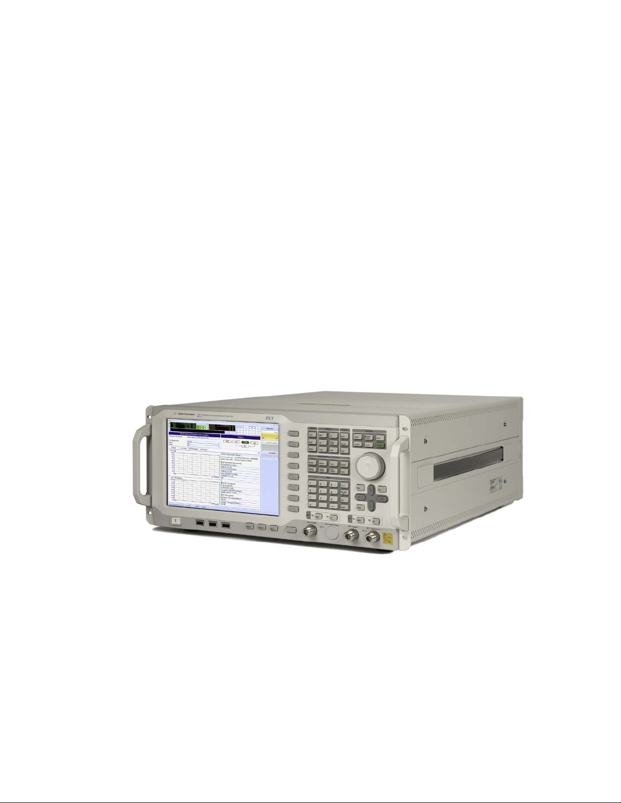
Agilent E6621A PXT Overview
The Agilent E6621A PXT is designed to test and analyze the performance and signaling of LTE UEs based
on the 3GPP standard. The PXT has two operating modes:
Figure 1-1: Agilent E6621A PXT Wireless Communications Test Set
Base Station Emulator (BSE)
In BSE mode, the PXT simulates the operation of an LTE eNodeB, for use in the development and test of
LTE UEs. In this mode, you can setup a call, establish a link, and transmit data.
Signal Analyzer (SA)
In Signal Analyzer (SA) mode, the PXT can be used to analyze LTE signals using modulation and spectrum
analysis. The Modulation Analysis mode displays the constellation and modulation errors of the signal.
The Spectrum Analysis functionality, implemented using a Fast Fourier Transform (FFT) algorithm, displays
the measured LTE signal in the frequency domain.
1
Page 12

Agilent PXT Wireless Communications Test Set
Location
Maximum Ambient Temperature
35° C
Table Top
45° C
User’s Guide
General Capabilities of the Agilent E6621A PXT
• Frequency Division Duplex (FDD) and Time Division Duplex (TDD) options
• Real-time 3GPP LTE downlink (DL) signal modulation and uplink (UL) demodulation
• eNodeB simulation with L1, L2 and L3 protocol stack
• Settable eNodeB, UE, and network operation parameters
• Settable frequency, power and modulation schemes
• SISO and MIMO testing capabilities
• Connection to Agilent 89600 VSA software for greater in-depth signal analysis
• VoLTE end-to-end functional voice testing capability
• LTE to LTE Handovers with two PXTs
• LTE to 2G/3G Handovers with PXT and 8960
• Support for Single Radio Voice Call Continuity (SRVCC) with PXT and 8960
General Specifications
Environmental
Operating Temperature:
Rack Mount
Storage Temperature: -20° C to +70° C
Altitude: 2000 meters (maximum)
Humidity: Maximum relative humidity is 80% for temperatures up to 31°C decreasing linearly to 50%
relative humidity at 40°C
This product is designed for indoor use, only.
Physical Specifications
Weight: 27.6 Kg max (depending on product option)
Dimensions: 222 H x 444 W x 600 D mm nominal
2
Page 13

Power Requirements
dangerous. Intentional interruption is prohibited. (IEC 348 clauses 17.3.3c & 17.3.4)
the specification.
Input Voltage Range: 100 to 240 VAC, automatic selection
Input Frequency Range: 50/60Hz
Input Current Rating: 5A @ 240 VAC (maximum)
7A @ 100 VAC (maximum)
Agilent PXT Wireless Communications Test Set
User’s Guide
WARNING
CAUTION
PXT Software Applications
Agilent N6050A LTE Mobile Test Software
This software application comes installed as a standard product on the PXT. It is the basis for all UE
testing. N6050A-7FP provides LTE-FDD base station emulation and N6050A-8FP provides LTE-TDD base
station emulation.
This is a Safety Class 1 Product (provided with a protective earthing ground
incorporated in the power cord). The mains plug shall only be inserted in a socket
outlet provided with a protective earth contact. Any interruption of the protective
conductor inside or outside of the instrument is likely to make the instrument
This instrument has an auto-ranging line voltage input. Ensure the supply voltage is
within the specified range.
When installing the product in a cabinet the convection into and out of the product
must not be restricted. The ambient temperature (outside the cabinet) must be less
than the maximum operating temperature of the product by 4° C for every 100 watts
dissipated in the cabinet. If the total power dissipated in the cabinet is greater than
800 watts, then forced convection must be used. It is your responsibility to ensure
the ambient temperature does not exceed the rated ambient temperature stated in
Agilent N6051A LTE RF Parametric Test with Test Mode Signaling
This software application is useful for RF design. It is installed in the PXT and includes a suite of LTE RF
measurements that are used for characterization, calibration, and verification purposes, available while on
a connection. This software application is optional.
Agilent N6052A LTE Functional and Application Test
This software application enables the PXT to provide a controlled environment where you can verify
network attach, idle and connected mode operation and functional performance such as throughput.
Maximum flexibility makes it possible for you to configure a range of connection and network parameters
where you can test, stress, and debug the protocol and data handling capabilities of designs including DL
2x2 MIMO and handovers. This software application is optional.
3
Page 14

Agilent PXT Wireless Communications Test Set
An active N6050AS Software and Technical Support Contract (STSC) is required to access
User’s Guide
Agilent N6061A Protocol Logging and Analysis
This application software is developed for use on systems running the Microsoft (MS) Windows XP or
Windows 7 operating systems. It displays and stores protocol and event logs of Agilent E6621A PXT. The
stored log files can be replayed and analyzed using this software and other advanced post-processing
tools. Please consult the Agilent LTE Protocol Logging and Analysis User’s Guide for more information.
Agilent N6062A Protocol Message Editor
This software application is developed for use on systems running the MS Windows XP or Windows 7
operating systems. The N6062A provides the ability to define RRC/NAS messages and event-driven
scenarios which can be utilized during the Base Station Emulator (BSE) operating mode of the Agilent
E6621A PXT. Please consult the Agilent LTE Message Editor User’s Guide for more information.
Latest Documentation
For the latest documentation on the above products, please go to www.agilent.com/find/pxt.
Latest Software Application Release
For the latest release of all PXT related software, please go to
http://www.agilent.com/find/softwaremanager
installation instructions.
. See “Upgrading Your Instrument Software” for
the software manager website (displayed above), together with the login credentials
registered by you or your company for activation. See the “Redeem Your Entitlement
Certificate” section in the Agilent PXT Wireless Communications Test Set Getting Started
Guide for instructions to activate your STSC.
Software and Technical Support Contracts
Software and Technical Support Contracts (STSC) entitle you to software updates and feature
enhancements, as well as direct access to a technical expert for technical support for a fixed period,
usually one year.
The STSC gives you direct access to technical product experts to increase your productivity and minimize
the software difficulties you encounter. These technical support engineers are experts on the E6621A PXT
test set, and its complementary software products. They have instant access to instruments and software
to enable them to resolve your issues as quickly as possible. Agilent will investigate all software defects
and operational problems reported through the technical support channel. Upon completion of the
investigation, we will advise you on possible solutions and functional alternatives. Where possible, Agilent
will provide software releases to address problems caused by defects in the firmware or software.
STSCs for the Agilent E6621A PXT
The N6050AS STSC covers the N6050A, N6051A and N6052A software applications running on the
E6621A PXT wireless communications test set, plus the associated N6061A and N6062A PC software
applications.
For more information on how to access technical support, refer to the section in the manual entitled,
Software and Technical Support Contracts
.
4
Page 15

Agilent PXT Wireless Communications Test Set
User’s Guide
2 Front-panel and Menu Keys
This chapter outlines the front-panel key menus for the E6621A PXT in the Base Station Emulator mode. All frontpanel keys are listed in alphabetical order. All other keys (menu keys) are listed in the order they appear in their
menu (that is, not in alphabetical order).
Please note the following while reading this chapter:
− When discussing key paths within tables or text, front-panel keys are represented in bold; menu keys
appear in bold, italics.
− To determine the hierarchy of the keys, refer to the bookmarks in the PDF by selecting View > Show/Hide >
Navigation Panels > Bookmarks.
− If the Mode row in the menu key parameter table does not specify FDD or TDD, then it is available in both
modulation formats.
− All front-panel keys associated with the SA mode are discussed in the chapter entitled, RF Measurements
on page 189
.
5
Page 16

Agilent PXT Wireless Communications Test Set
The PXT calculates the RSTP for you. See the RF1 Amplitude (RSTP) and RF2
Bandwidth
Number of Resource Elements in Bandwidth
5
300
10
600
20
1200
User’s Guide
Amp
(Amplitude) This front-panel key displays the following menu of keys.
Amplitude
RF1 Amplitude
RF2 Amplitude
RF1 Amplitude (RSTP)
RF2 Amplitude (RSTP)
AWGN
Key Path: Front-panel key
Amplitude
Sets the RF1/RF2 power level(s) in dBm.
This amplitude level represents the integrated power level, assuming all resource elements in the
bandwidth are occupied. It is sometimes called Channel BW Power (see 36.521-1 Appendix C.0) and, when
doing sensitivity testing, is equivalent to the concept of P
In order to determine the true Reference Signal Receive Power (RSRP), it is necessary to take into
consideration the actual number of occupied resource elements in the bandwidth.
Amplitude (RSTP) menu keys.
(see chapter 7 of 36.521-1).
REFSENS
Because reference signals are always transmitted and RSRP = Reference Signal Transmit Power (RSTP)
when the path loss is 0, the equation below is always true:
RSTP power level = PXT Amplitude – 10 log
bandwidth)
For example: If the BW = 10 MHz:
RSTP power level = PXT Amplitude - 10 log
= PXT Amplitude – 27.8
RSRP is defined in 3GPP TS 36.133, section 9.1.4.
For more information on RSRP, see the Meas > Information key description on page 77
For more information on how power level settings can affect the ability for the UE to connect, see UE is
not connecting.
10
(600)
(number of resource elements in the cell
10
.
6
Page 17

Mode
BSE. SA
Range
−120 dBm to +10 dBm
Preset
−57 dBm
State Saved
Yes
Dependencies and/or Couplings
Coupled to RF1/RF2 Amplitude
Initial S/W Revision
6.0
Key Path
Amp
RF1 Amplitude
The specified output power for the RF out port is −110 dBm to −10 dBm.
Mode
BSE. SA
Range
−120 dBm to +10 dBm
Preset
−57 dBm
State Saved
Yes
Dependencies and/or Couplings
Coupled to RF1 Amplitude (RSTP)
Initial S/W Revision
6.0
Key Path
Amp
The specified output power for the RF out port is −110 dBm to −10 dBm.
Mode
BSE. SA
Range
−120 dBm to +10 dBm
Preset
−57 dBm
State Saved
Yes
Dependencies and/or Couplings
Coupled to RF2 Amplitude (RSTP)
Initial S/W Revision
6.0
Key Path
Amp
Sets the output power level in dBm for RF1.
Agilent PXT Wireless Communications Test Set
User’s Guide
The specified output power for the RF in/out port is −110 dBm to −15 dBm.
RF2 Amplitude
Sets the output power level in dBm for RF2.
The specified output power for the RF in/out port is −110 dBm to −15 dBm.
7
Page 18

Agilent PXT Wireless Communications Test Set
Mode
BSE. SA
Range
−150.79 dBm (for 20MHz Channel Bandwidth) to −14.77 dBm (for 5MHz)
Preset
− 84.78 dBm
State Saved
Yes
the bandwidth.
Initial S/W Revision
6.3
Key Path
Amp
Mode
BSE. SA
Range
−150.79 dBm (for 20MHz Channel Bandwidth) to −14.77 dBm (for 5MHz)
Preset
−84 78 dBm
State Saved
Yes
the bandwidth.
Initial S/W Revision
6.3
Key Path
Amp
User’s Guide
RF1 Amplitude (RSTP)
The value displayed on this menu key is read-only and is the RF1 amplitude expressed as an RSTP power
level determined by the following equation:
RSTP = Cell Power – 10 log
Dependencies and/or Couplings Read-only key dependent upon cell power and number of subcarriers in
(number of subcarriers in the bandwidth)
10
RF2 Amplitude (RSTP)
The value displayed on this menu key is read-only and is the RF2 amplitude expressed as an RSTP power
level determined by the following equation:
RSTP = Cell Power – 10 log
Dependencies and/or Couplings Read-only key dependent upon cell power and number of subcarriers in
(number of sub-carriers in the bandwidth)
10
8
Page 19
Agilent PXT Wireless Communications Test Set
oc
N
You can change the cell power level without changing AWGN settings, enabling
Mode
BSE, SA
power and is therefore dependent upon the cell power.
AWGN for TDD added in software version 6.5.
Key Path
Amp
Mode
BSE, SA
Range
On | Off
Preset
Off
Initial S/W Revision
6.3
Key Path
Amp > AWGN
AWGN
AWGN, also referred to as
noise source (average power per resource element (RE) normalized to the subcarrier spacing), simulating
interference from cells, as measured at the UE antenna connector.
Note that the AWGN is determined by using a signal to noise ratio relative to the cell power.
This menu key enables you to access the following functions:
, in 3GPP specifications, is defined as the power spectral density of a white
you to maintain a constant signal to noise ratio, when required.
User’s Guide
Apply AWGN
Signal to Noise Ratio (RF1)
Signal to Noise Ratio (RF2)
Noc (RF1)
Noc (RF2)
Noise Amplitude (RF1)
Noise Amplitude (RF2)
AWGN MIMO Channel Mode
Dependencies and/or Couplings AWGN is determined by using a signal to noise ratio relative to the cell
Initial S/W Revision 6.3
Apply AWGN
On: Applies AWGN to the signal.
Off: Turns off AWGN.
9
Page 20

Agilent PXT Wireless Communications Test Set
Mode
BSE, SA
Range
−10 to +30
Preset
0
Initial S/W Revision
6.3
Key Path
Amp > AWGN
Mode
BSE, SA
Range
−10 to +30
Preset
0
Initial S/W Revision
6.3
Key Path
Amp > AWGN
oc
N
where the bandwidth is set equal to the serving cell channel bandwidth profile.
Mode
BSE, SA
Bandwidth)
Dependencies and/or Couplings
Read-only key
Initial S/W Revision
6.3
Key Path
Amp > AWGN
User’s Guide
Signal to Noise Ratio (RF1)
Specifies the desired signal to noise ratio for antenna port 1. Using the current amplitude, this value
determines the power level of AWGN applied to the signal.
Signal to Noise Ratio (RF2)
Specifies the desired signal to noise ratio for antenna port 2.This value is based on the current amplitude
and sets the power level of AWGN.
Noc (RF1)
Displays the resultant value of AWGN power level relative to a single resource element (as described in
3GPP 36.521-1) for RF port 1. This is the power level of AWGN relative to a single resource element given
the SNR RF1 and cell power setting.
Most of the RF conformance tests are expected to use
Value = Noise Amplitude (RF1) – 10 log10(Number Resource Elements in
(AWGN) = -98 [dBm/15kHz]
10
Page 21

Agilent PXT Wireless Communications Test Set
where the bandwidth is set equal to the serving cell channel bandwidth profile.
Mode
BSE, SA
Bandwidth)
Dependencies and/or Couplings
Read-only key
Initial S/W Revision
6.3
Key Path
Amp > AWGN
Mode
BSE. SA
Value
= RF1 Amplitude – Signal to Noise Ratio (RF1)
Preset
−57
Dependencies and/or Couplings
Read-only key.
Initial S/W Revision
6.3
Key Path
Amp > AWGN
Mode
BSE, SA
Value
= RF1 Amplitude – Signal to Noise Ratio (RF2)
Preset
−57
Dependencies and/or Couplings
Read-only key
Initial S/W Revision
6.3
Key Path
Amp > AWGN
User’s Guide
Noc (RF2)
Displays the resultant value of AWGN power level relative to a single resource element (as described in
3GPP 36.521-1) for antenna port 2. This is the power level of AWGN relative to a single resource element,
given the SNR RF2 and cell power setting.
Most of the RF conformance tests are expected to use (AWGN) = −98 [dBm/15kHz]
Value = Noise Amplitude (RF2) – 10 log10(Number Resource Elements in
Noise Amplitude (RF1)
Displays the AWGN power level of antenna port 1 as an integrated power level, which is the same terms
used to set or display the total Cell power RF1 amplitude.
Noise Amplitude (RF2)
Displays the AWGN power level of antenna port 2 as an integrated power level, which is the same terms
used to set or display the total Cell power RF2 amplitude.
11
Page 22

Agilent PXT Wireless Communications Test Set
Mode
BSE, SA
Range
MIMO | Normal
Preset
Normal
Initial S/W Revision
6.3
Key Path
Amp > AWGN
Mode
BSE, SA
Range
–120 dBm to +50 dBm
Units
dBm
Initial S/W Revision
6.0
Key Path
Atten
If the reference (or attenuation) levels are incorrectly set, causing an overload
To ensure your measurement results are displayed correctly, compensate for
User’s Guide
AWGN MIMO Channel Mode
Enables you to set the AWGN for a MIMO model or for a Normal model (not MIMO).
MIMO: Sets AWGN for both paths of the MIMO channel setup.
Normal: Sets AWGN for normal channel setup.
Atten – Key Menu 1
(Attenuation) Accesses the settings that enable you to control the receiver level(s).
Ref Level
RF1 Ref Level
RF2 Ref Level
Attenuation
RF1 Input Attenuation
RF2 Input Attenuation
Key Path: Front-panel key
Ref Level
Sets the expected receiver level(s) for RF1.
CAUTION
condition, the red OVF warning indicator in the top right of the display illuminates. In
this case, increase the reference level or attenuation until the warning indicator turns
off.
external loss or gain by setting Atten > More > RF1 Input Power Offset.
12
Page 23

Agilent PXT Wireless Communications Test Set
Mode
BSE. SA
Range
-120 dBm to +10 dBm
Preset
-57 dBm
State Saved
Yes for BSE mode. No for SA mode.
Dependencies and/or Couplings
Grayed out when Atten > Attenuation is set to Adaptive.
Initial S/W Revision
6.0
Key Path
Atten
Mode
BSE. SA
Range
-120 dBm to +10 dBm
Preset
-57 dBm
State Saved
Yes for BSE mode. No for SA mode.
Dependencies and/or Couplings
Grayed out when Atten > Attenuation is set to Adaptive.
Initial S/W Revision
6.0
Key Path
Atten
To ensure your measurement results are displayed correctly, compensate for
User’s Guide
RF1 Ref Level
Sets the expected receiver level for RF1 when you wish to specify different values for RF1 and RF2 inputs.
Otherwise, this value is set by pressing Atten > Ref Level.
RF2 Ref Level
This function is currently not available.
Attenuation
Manual: Enables you to define the attenuation level(s) for RF1.
Auto: Enables the PXT to calculate and set the optimum attenuation value based on the reference level
(and other internal parameters) set by pressing Atten > Ref Level.
Adaptive: Automatically adjusts the attenuation when the overflow (OVF) alarm is detected.
For example, if you wish to increase the number of uplink RBs, effectively increasing the UE power
consumption, the PXT automatically adjusts the attenuation to compensate for this change. See Adaptive
Attenuation – More Information.
Setting the Attenuation to Adaptive
• IDLE_ADJUSTER
• CONNECTED_ADJUSTER
• OVF_ADJUSTER
For more information on how power level settings can affect the ability for the UE to connect, see UE is
not connecting.
external loss or gain by setting Atten > More > RF1 Input Power Offset.
enables three options:
13
Page 24

Agilent PXT Wireless Communications Test Set
Mode
BSE, SA
Range
Auto | Manual | Adaptive
Preset
Auto
Dependencies/Couplings
This menu key is coupled to RF1 Input Attenuation settings.
but the reverse is not true.
Key Path
Atten
User’s Guide
Initial S/W Revision 6.0
Adaptive attenuation was added in software revision 6.4.
Selecting Func > UE Power Control > CLCP sets Attenuation = Adaptive
Adaptive Attenuation - More Information
Adaptive attenuation is intended to eliminate manual attenuation control when the UL or DL path loss is
indeterminate, and allows automatic control by the instrument.
The simplest way of demonstrating adaptive attenuation is to connect your device, set UL Resource
Allocation Mode to Fixed Mac Padding
Resource Allocation), then Press SA > Func > UE Power Control and adjust the power. The power
measurement must track the power control settings sent to the UE, therefore you must set Power Adjust
(All Up) = On
.
(Mode > BSE > Mode Setup > More > PHY Settings > UL
With the default settings, you may find this process a little slow to adjust. If this is the case, use the OVF
adjuster button (Atten > More > OFV_ADJUSTER) to 5 dB and re-try. Then, set Power Adjust (All Down) =
On
, as shown in the figure below.
14
Page 25

Agilent PXT Wireless Communications Test Set
DO NOT SIMPLY SET Power Adjust (All Down) = Off. This results in a dropped connection
1. Measurement results are not affected by this setting. To change the
Mode
BSE, SA
Range
Auto | Manual
Preset
Auto
Initial S/W Revision
6.0
Key Path
Atten
User’s Guide
(under investigation), because the PXT adjusts the attenuator too high. To alleviate this
issue, always switch back to the setting: Power Adjust (All UP) = On
this screen.
briefly, before leaving
OTA Example Settings for Adaptive Attenuation
It has been found that for some devices, the following OTA settings are successful when using the
adaptive attenuation function.
Set Atten > Attenuation = Adaptive
Set the Output Power Offset to +40 dBm on both RF1 and RF2 (Config > Amplitude Offsets > RF1/RF2
Output Power Offset).
Set IDLE_ADJUSTER (Atten > More > IDLE_ADJUSTER ) and CONNECTED_ADJUSTER (Atten > More >
CONNECTED_ADJUSTER ) both to -30 dBm.
Set UL Resource Allocation Mode to Fixed Mac Padding
Settings > UL Resource Allocation). Note that if Atten > Attenuation = Auto
alternative to setting the UL Resource Allocation Mode to Fixed Mac Padding
(All Up) = On
or Func > UE Power Control > Power Control Mode = CLCP.
.
(Mode > BSE > Mode Setup > More > PHY
, this is not required. An
, is to set UL Power Adjust
RF1 Input Attenuation
Auto: Enables the PXT to use the value set for Atten > RF1 Ref Level to calculate the required input
attenuation. Otherwise, this value is set by the Attenuation menu key.
Manual: Enables you to set the RF1 input attenuation value manually.
offset of your measurement results, use the Atten > RF1 Input Power
Offset setting.
2. The maximum power level to this input is: 27 dBm (.5 Watts) 5VDC.
RF2 Input Attenuation
This function is currently not available.
15
Page 26

Agilent PXT Wireless Communications Test Set
Mode
BSE, SA
Range
1 dB to 20 dB
Units
dB
Preset
10
Initial S/W Revision
6.0
Key Path
Atten > More
Mode
BSE
Overwrites Scenario File Value
Yes
Range
-30 to 30
Units
dB
Preset
6
Dependencies and/or Couplings
Available only when Attenuation is set to Adaptive.
Initial S/W Revision
6.4
Key Path
Atten > More
User’s Guide
Atten – Key Menu 2
(Attenuation) Accesses the following settings.
Scale/Div
IDLE_ADJUSTER
CONNECTED_ADJUSTER
OVF_ADJUSTER
Key Path: Front-panel key
Scale/Div
Sets the units per vertical graticule division on the display.
IDLE_ADJUSTER
This parameter is automatically set by the PXT when Attenuation is set to Adaptive.
When the connection status is Idle or unavailable, the PXT is waiting for PRACH to be transmitted by the
UE.
The expected input value is automatically set to the level expected for a PRACH, with a few dB of headroom.
This value allows that expected input value to be increased or decreased – if it is expected that the UE may
be transmitting above or below the expected value.
16
Page 27

Agilent PXT Wireless Communications Test Set
Mode
BSE
Overwrites Scenario File Value
Yes
Range
-30 to 30
Units
dB
Preset
0
Dependencies and/or Couplings
Available only when Attenuation is set to Adaptive.
Initial S/W Revision
6.4
Key Path
Atten > More
Mode
BSE
Overwrites Scenario File Value
Yes
Range
0 to 10
Units
dB
Preset
1
Dependencies and/or Couplings
Available only when Attenuation is set to Adaptive.
Initial S/W Revision
6.4
Key Path
Atten > More
User’s Guide
CONNECTED_ADJUSTER
This parameter is automatically set by the PXT when Attenuation is set to Adaptive.
This value is an adjustment applied to the expected input value when the UE is in the connected state.
OVF_ADJUSTER
This parameter is automatically set by the PXT when Attenuation is set to Adaptive.
If an overflow (OVF) is detected, as designated by the OVF light on the front-panel, this menu key enables
you to adjust the size of the automatic adjustments to the attenuation setting that will be made in Adaptive
mode to ensure accurate uplink power measurements are being made.
It should not be necessary for you to change the value of this parameter.
BSE
In the Base Station Emulator (eNodeB emulation) mode, the PXT simulates an LTE eNodeB's operation for use
in the development and test of LTE UEs. In this mode, you test the UE by setting up a call and establishing a
link.
Key Path: Front-panel key (Note: You may have to press the Mode key to obtain the menu keys below.)
Emulator Mode
The eNodeB simulation starts and stops by pressing this menu key. If simulation has started, the
instrument is ready to be connected with the UE. When simulation stops, the instrument transmits only
default signals in the downlink and all the tests are frozen.
Key Path: Mode > BSE
17
Page 28

Agilent PXT Wireless Communications Test Set
Mode
BSE
Range
Run | Stop
Preset
Stop
Initial S/W Revision
6.0
Key Path
Mode > BSE
User’s Guide
Config
(Configuration) This front-panel key displays the following menu of functions:
RF Setup
Network Setup
Cell Setup
External Sync
Amplitude Offsets
General Config
Key Path: Front-panel key
RF Setup
Accesses the available parameters you can set to configure the RF in the BSE mode. Refer to RF
Measurements section for more information on the menus below.
RF Input Control
RF Output Control
Ref. Clock Source
Key Path: Config
RF Input Control
This menu key activates the following menu of functions:
Input Mode
Input Source
RF Select
Ext Cell Select
Refer to RF Measurements
Key Path: Config > RF Setup
section for more information on the menus below.
18
Page 29

Agilent PXT Wireless Communications Test Set
Mode
BSE, SA
Range
Int | Ext
Preset
Int
Initial S/W Revision
6.0
Key Path
Config > RF Setup > RF Input Control
Mode
BSE, SA
Range
IF | IQ
Preset
IF
Initial S/W Revision
6.0
Key Path
Config > RF Setup > RF Input Control
Mode
BSE, SA
Range
A-Cell | B-Cell
Preset
B-Cell
Initial S/W Revision
6.0
Key Path
Config > RF Setup > RF Input Control
User’s Guide
Input Mode
Int: When set to internal, the front-panel inputs are active.
Ext: When set to external, the Input Source key is activated to enable selection from the rear panel inputs.
Input Source
IF: When set to IF, the uplink rear panel inputs accept IF signals.
IQ: When set to IQ, the uplink inputs accept analog IQ signals and the downlink analog IQ outputs and
inputs are active.
RF Select
Sets RF port.
Key Path: Config > RF Setup > RF Input Control
Ext Cell Select
Sets the cell (A or B) for which you are defining all parameters.
RF Output Control
This menu key activates the following menu of functions:
RF DL Output
RF1 Front Output
RF2 Front Output
19
Page 30

Agilent PXT Wireless Communications Test Set
Mode
BSE, SA
Range
Int | Ext
Preset
Int
Initial S/W Revision
6.0
Key Path
Config > RF Setup > RF Output Control
Mode
BSE, SA
Range
TRX | TX
Preset
TRX
Initial S/W Revision
6.0
Key Path
Config > RF Setup > RF Output Control
Mode
BSE, SA
Range
TRX | TX
Preset
TRX
Initial S/W Revision
6.0
Key Path
Config > RF Setup > RF Output Control
User’s Guide
Ext Cell Select
Refer to RF Measurements
Key Path: Config > RF Setup
section for more information on the menus below.
RF DL Output
Enables external processing of the IQ signals (for example: fading) before RF up-conversion takes place.
There are four BNC outputs associated with this menu key: I1 OUTPUT, Q1 OUTPUT, I2 OUTPUT, and
Q2 OUTPUT. The corresponding inputs are: I1 RETURN, Q1 RETURN, I2 RETURN, and Q2 RETURN.
RF1 Front Output
TRX: Indicates that the DL RF1 Output is present on the antenna port labeled RF1 Input/Output.
TX: Indicates that the DL RF1 Output is present on the antenna port labeled RF1 Output.
RF2 Front Output
TRX: Currently not available because RF2 Input/Output is not available.
TX: Indicates that the DL RF2 Output is present on the antenna port labeled RF2 Output.
20
Page 31

Ext Cell Select
You must select External, by pressing BSE > Config > RF Output Control > RF DL
Mode
BSE
Range
A-Cell | B-Cell
Preset
B-cell
SCPI command introduced at 6.3
Key Path
Config > RF Setup > RF Output Control
Agilent PXT Wireless Communications Test Set
User’s Guide
A-Cell: Enables external processing (for example: fading) of internally generated IQ signals, as described in
RF DL Output
B-Cell: Enables an external signal to be injected into B-Cell via the I/IF INPUT and Q/IF INPUT BNCs,
where it is processed and pushed back out through the IQ OUTPUT BNCs.
Initial S/W Revision Menu key present at 6.0.
, above.
Output to enable the functionality of this key.
Ref. Clock Source
Auto enables the timing synch to come from external or internal (the E6621A PXT) sources. The blocks at
the top-right of the display indicate external (EXT) or internal (INT) in yellow to show these conditions are
met.
Internal sets the timing synch to come from inside the PXT. If you connect an external clock source, it will
disregard it and continue to use the internal clock as the reference.
Key Path: Config > RF Setup
Network Setup
This menu key accesses the topics that enable you to configure your network.
IP Setup
Remote Ctrl Setup
EPC Setup
Key Path: Config
IP Setup
Internet Protocol (IP) setup enables you to set the IP addresses for the following components.
IP
Netmask
Gateway
DNS
OK
All parameters set in this menu are persistent through an instrument power cycle.
Key Path: Config > Network Setup
21
Page 32

Agilent PXT Wireless Communications Test Set
IP address of the PXT is needed to connect to the N6061A Protocol Logging and
Remote API DLL.
Remote API DLL.
User’s Guide
IP
Sets the PXT IP address.
The IP address is persistent through a power cycle of the PXT.
Key Path: Config > Network Setup > IP Setup
Analysis tool, the N6062A Protocol Message Editor tool, and the E6621A Remote
API DLL.
Netmask
This value is a 32-bit mask used to divide an IP address into subnets and specify the networks available
hosts.
The netmask IP address is needed to connect to the N6061A Protocol Logging
This setting is persistent through an instrument power cycle.
Key Path: Config > Network Setup > IP Setup
and Analysis tool, the N6062A Protocol Message Editor tool, and the E6621A
Gateway
This IP address is that address for the computer or network that enables or controls access to the other
computers or a network you are accessing. When you are doing end-to-end data, this is the address to
which uplink data will be sent. It could be an application server or a router on your network.
The gateway IP address is needed to connect to the N6061A Protocol Logging
This setting is persistent through an instrument power cycle.
Key Path: Config > Network Setup > IP Setup
and Analysis tool, the N6062A Protocol Message Editor tool, and the E6621A
DNS
Directory Name Service (DNS)
Set this if you have a DNS on your network.
This setting is persistent through an instrument power cycle.
Key Path: Config > Network Setup > IP Setup
22
Page 33

Agilent PXT Wireless Communications Test Set
Mode
BSE, SA
Initial S/W Revision
6.4
Key Path
Config > Network Setup
User’s Guide
OK
After designating all the necessary IP addresses above, press this key to activate these settings. Changes
to the IP configuration will not take effect until the OK key is pressed.
Key Path: Config > Network Setup > IP Setup
Remote Ctrl Setup
This key accesses the menus to configure remote control of the PXT using either .DLL or GPIB.
The settings in this menu are all persistent through an instrument power cycle.
Key Path: Config > Network Setup
TCP/IP
Accesses the key menu that enables you to specify and activate TCP/IP port.
Key Path: Config > Network Setup > Remote Control Setup
Port
Specifies the port number used to control the PXT if remote control is to be performed over TCP/IP.
The port number specified here must match that used in the E6621_Connect command (one of the API
commands supported by the E6621A Remote API DLL).
Key Path: Config > Network Setup > Remote Control Setup > TCP/IP
GPIB
Accesses the key menu that enables you to specify and activate the GPIB address.
This setting is persistent through an instrument power cycle.
Key Path: Config > Network Setup > Remote Control Setup
GPIB Address
Specifies the GPIB address used to control the PXT if remote control is to be performed over GPIB.
Key Path: Config > Network Setup > Remote Control Setup > GPIB
EPC Setup
Accesses the settings that enable you to use the EPC. For more information, see EPC Setup on page 144.
23
Page 34

Agilent PXT Wireless Communications Test Set
Initial S/W Revision
6.4
Key Path
Config > Network Setup > EPC Setup
Initial S/W Revision
6.4
Key Path
Config > Network Setup > EPC Setup > PXT Connections
Initial S/W Revision
6.4
Key Path
Config > Network Setup > EPC Setup > PXT Connections
Mode
BSE, SA
Range
0 to 100
Units
%
Preset
100%
Dependencies and/or Couplings
This setting is coupled to B-Cell Ratio.
Initial S/W Revision
6.0
Key Path
Config > Cell Setup
User’s Guide
PXT Connections
Displays the current value for PXT IP Address #1 and accesses the key menu that enables you to change
this address and/or connect to the EPC.
PXT IP Address #1
With each key press, a different IP address segment (delineated by a period) is underlined. When the
desired segment is underlined, set the numeric value using the front-panel numeric keypad and select
Enter.
External EPC
Enables you to connect or disconnect to the external EPC.
‘Connect’must be selected when using the EPC. For more information about using the EPC refer to
on page 85 and EPC Setup on page 144.
EPC
Cell Setup
Accesses the menus enabling you to setup the following parameters:
A-Cell Ratio
B-Cell Ratio
Cell Selection
Key Path: Config
A-Cell Ratio
Selects the ratio in percent of the relative power allocated to A-cell compared to B-cell. For example, if Acell is set to 80%, then B-cell is set to 20%.
24
Page 35

Agilent PXT Wireless Communications Test Set
Mode
BSE, SA
Range
0 to 100
Units
%
Preset
0%
Dependencies and/or Couplings
This setting is coupled to A-Cell Ratio.
Initial S/W Revision
6.0
Key Path
Config > Cell Setup
Mode
BSE, SA
Range
Acell | Bcell
Preset
Acell
Initial S/W Revision
6.0
Key Path
Config > Cell Setup > Cell Selection
User’s Guide
B-Cell Ratio
Selects the ratio in percent of the relative power allocated to B-cell compared to A-cell. For example, if Bcell is set to 100%, then A-cell is set to 0%.
Cell Selection
Accesses the available parameters you can set to configure the selection of the cell.
Key Path: Config > Cell Setup
Cell Selection
Sets the active cell to which all other cell settings pertain. This includes the loading of scenario files
and the sending of any custom or other messages you initiate within the N6062A Protocol Message
Editor software.
Copy PHY Parameter - Acell to Bcell
Copies the PHY layer parameters from cell A to cell B.
Note: This function is useful when using the PXT to emulate two cells simultaneously and the PHY
settings must be identical. See “Testing Two Cells Using One PXT” on page 165
Key Path: Config > Cell Setup > Cell Selection
for more information.
Copy PHY Parameter - Bcell to Acell
Copies the PHY layer parameters from cell B to cell A.
Note: This function is useful when using the PXT to emulate two cells simultaneously and the PHY
settings must be identical. See “Testing Two Cells Using One PXT” on page 165
for more information.
Key Path: Config > Cell Setup > Cell Selection
External Sync
Accesses the SIB8 Force Sync key,
25
Page 36

Agilent PXT Wireless Communications Test Set
Mode
BSE
Initial S/W Revision
6.3
Key Path
Mode > BSE > Config
If you include an SIB8 message in the scenario file, the following occurs:
Mode
BSE
Initial S/W Revision
6.3
Key Path
Mode > BSE > Config > External Sync
Mode
BSE
Instrument S/W Revision
6.4
Key Path
Mode > BSE/SA > Config > External Sync
User’s Guide
SIB8 Force Sync
Pressing this key enables the following:
1. Resets the value of synchronousSystemTime inside the SIB8 message to the value specified in the
scenario file.
2. Sends an external trigger signal at the beginning of the subframe to transmit this same SIB8 message
containing the reset value.
• The synchronousSystemTime parameter increments by one with each
transmission of SIB8.
• The first transmission of SIB8 sends a trigger at the beginning of the
subframe. This trigger signal replaces the frame trigger.
• Frame triggering is disabled.
Security Sync
This function is used to force the security context of one PXT to be sent to another one. You should not
normally need to use this because during a handover or re-selection, the context is transferred
automatically.
26
Page 37

Agilent PXT Wireless Communications Test Set
Mode
BSE, SA
Initial S/W Revision
6.4
Key Path
Mode > BSE > Config
Mode
BSE, SA
Range
-100 dB to +100 dB
Preset
0 dB
instrument preset.
Initial S/W Revision
6.4
Key Path
Mode > Config > Amplitude Offsets
User’s Guide
Amplitude Offsets
Accesses the amplitude offsets table and menu keys.
Amplitude offsets compensate for loss or gain between the test set's RF IN/OUT front panel connector and
the UE's RF connector.
Amplitude offset settings are preserved during power cycles or instrument preset.
There are two methods for entering offsets. They do not interact with each other. You must choose to use
one or the other method.
• The tabular method which defines frequency vs. offset compensation (operates exactly like that in
the 8960 One Box Tester). For more information, see The Tabular Method
• The globally applied offsets method which applies a single value offset to the RF input and a
separately defined single value offset to RF output.
, below.
Amplitude Offset Table
This menu key determines whether the Amplitude Offset Table is applied (On) or not (Off).
On: Applies offsets based on the values in the table. Disables input and output offset menu keys.
Off: Disables table offset values, so they are not applied. Enables input and output offset menu keys.
For more information, see The Tabular Method
State Saved Amplitude offset settings are preserved during power cycles or
, below.
The Tabular Method
Since some cables have different losses at different frequencies, you may want to characterize their cable
loss over frequency. This effect is especially seen where the UE supports multiple bands and the range of
frequencies is high. This amplitude offset feature enables you to enter the losses into a table and allow the
PXT to handle this compensation automatically. As the DL and UL frequency used by the PXT changes, the
offset values are also changed according to the settings you specify in the table.
Using the tabular method enables you to enter frequency dependent values for path loss unlike the global
application of path loss which is applied when you use RF1 Output Power Offset, RF2 Output Power Offset,
RF1 Input Power Offset menu keys.
or
27
Page 38

Agilent PXT Wireless Communications Test Set
User’s Guide
Figure 2 – 1: Offsets Applicable to Band 4 Frequencies
The table above is an example of how you would set the offsets applicable to Band 4 frequencies. It
displays the points for the upper/lower boundaries of the uplink, and likewise for the downlink. This
simplistic model provides a constant offset of -32dB on the received uplink path (32 dB of path loss), and -7
dB for the downlink. The result of the PXT’s downlink power is boosted by 7 dB (whether you are using RF1
or RF2 as the output port), and the received uplink signal has 32 dB of compensation applied to its
measurement result.
You would want to add more frequency points to fully describe the losses across the uplink and downlink
paths.
These offset values are also used by the Adaptive Attenuation feature on page 13
For more information regarding how offsets are determined between specified frequencies, see Amplitude
Offsets Between Frequency Settings and Amplitude Offsets, Channel Bandwidths, and Center frequency.
to determine the correct amount of attenuation required for the Idle and
Connected Adjuster values.
28
Page 39

Agilent PXT Wireless Communications Test Set
User’s Guide
Amplitude Offsets Between Frequency Points
If mobile station testing is performed at frequencies that are not present in the table, the test set uses an
offset based on a linear interpolation using the two frequency points adjacent to it.
For example, Figure 2-2, below shows four amplitude offsets for frequencies ranging from 890 MHz to
920 MHz.
Frequency (MHz) Offset (dB)
890 -1.00
900 -2.00
910 -3.00
920 -4.00
For test frequencies between the lowest (890 MHz) and highest (920 MHz) frequency points that are not
entered in the table, the PXT calculates offsets using piece-wise linear interpolation.
Each of the four points is shown on a non-scaled frequency versus amplitude offset graph. At a test
frequency of 895 MHz, which is midway between point number one (-1 dB) and point number two (-2 dB)
the PXT applies an offset of -1.5 dB.
Figure 2-2 Interpolated Offset Value
If testing is done outside the range of frequencies bounded by the lowest and highest frequency entries, the
PXT simply uses the amplitude offset that is paired with the nearest frequency point.
Amplitude Offsets, Channel Bandwidths, and Center frequency
Offsets are applied based on center frequency. The PXT finds the closest value to the centre frequency of
the uplink/downlink and applies this offset (using interpolation if needed) to the entire
bandwidth/subcarriers.
Examples
If you have specified amplitude offset values for 2.5 GHz and 800 MHz in the amplitude offset table, the PXT
responds as described below when you set the PXT to the following frequencies:
1. 1.5 GHz – the PXT uses interpolation to find the correct value.
2. 350 MHz – the PXT uses the same offset value as is specified for 800 MHz.
29
Page 40

Agilent PXT Wireless Communications Test Set
Mode
BSE, SA
Range
1 to 60
Initial S/W Revision
6.4
Key Path
Mode > Config > Amplitude Offsets
Mode
BSE, SA
Range
350 MHz to 6.0 GHz
Preset
2.5 GHz
preset.
Initial S/W Revision
6.4
Key Path
Mode > Config > Amplitude Offsets
Prior to software version 6.4, the PXT used negative values to represent a gain
User’s Guide
RF In/Out Offset
Selects the offset number (which is a point as shown on the graph in Figure XX, above) for which you wish
to specify frequency, offset, and state values. The offset selected is highlighted on the display. See red
column shown in Figure 2 – 1, above.
Frequency
Sets the frequency value for the offset you have highlighted in the Amplitude Offset Table. See navy blue
column in Figure 2-1, above.
For more information regarding how offsets are determined between specified frequencies, see Amplitude
Offsets Between Frequency Settings and Amplitude Offsets, Channel Bandwidths, and Center frequency.
Staved Saved Frequency values are preserved during power cycles or instrument
Offset
Sets the offset value in dB for the offset you have highlighted. See turquoise column of values in Figure 21, above.
This feature provides the ability to implement path loss/gain compensation using a table of values for
specific frequencies. Loss is entered as a negative and gain is entered as a positive.
For example: +40 dB of loss is entered as – 40 dB.
+40 dB of gain is entered as +40 dB.
For more information about how to set offsets, see The Tabular Method on page 27.
For more information regarding how offsets are determined between specified frequencies, see Amplitude
Offsets Between Frequency Settings and Amplitude Offsets, Channel Bandwidths, and Center frequency.
and positive values to represent a loss. That sense offset has been reversed to
align with other Agilent products, for example the 8960.
30
Page 41

Agilent PXT Wireless Communications Test Set
Mode
BSE, SA
Range
-100 dB to +100 dB
Preset
0 dB
instrument preset.
Initial S/W Revision
6.4
Key Path
Mode > Config > Amplitude Offsets
Mode
BSE, SA
Range
On | Off
Preset
Off
State Saved
State settings are preserved during power cycles or instrument preset.
Initial S/W Revision
6.4
Key Path
Mode > BSE/SA > Config > Amplitude Offsets
Mode
BSE, SA
Range
–100 dB to +100 dB
Units
dB
Preset
0
Initial S/W Revision
6.0
Key Path
Mode > BSE/SA > Config > Amplitude Offsets
User’s Guide
State Saved Amplitude offset settings are preserved during power cycles or
State
Determines whether the offset selected is applied (On/Off) to the offset you have highlighted and/or used
in the interpolation calculation when applicable. See pink column shown in Figure 2 – 1, above.
RF1 Output Power Offset
Enables you to specify an amplitude offset to compensate for a gain or loss between the RF1 Output and
the UE. For example: If there is a 40 dB loss, then set this value to -40 dB, thereby increasing the output
power of the instrument by 40 dB. This loss is applied globally. Frequency dependent definition of loss is
available by using The Tabular Method
Refer to Meas > Information section (calculating RSRP/RSTP) on page 77
Maximum RF1 Output power is -10dBm.
described above.
for more information.
RF2 Output Power Offset
Enables you to specify an amplitude offset to compensate for a gain or loss between the RF2 Output and
the UE. For example: If there is a 40 dB loss, then set this value to +40 dB, thereby increasing the output
power of the instrument by 40 dB. This loss is applied globally. Frequency dependent definition of loss is
available by using The Tabular Method
Refer to Meas > Information section (calculating RSRP/RSTP) on page 77
described above.
for more information.
31
Page 42

Agilent PXT Wireless Communications Test Set
Mode
BSE, SA
Range
–100 dB to +100 dB
Units
dB
Preset
0
Initial S/W Revision
6.0
Key Path
Mode > BSE/SA > Config > Amplitude Offsets
This setting does NOT adjust the input attenuation. You must set the
Mode
BSE, SA
Range
–100 dB to +100 dB
Units
dB
Preset
0
Initial S/W Revision
6.0
Key Path
Mode > BSE/SA > Config > Amplitude Offsets
Mode
BSE, SA
Initial S/W Revision
6.4
Key Path
Mode > BSE/SA > Config
User’s Guide
This setting is primarily used with testing MIMO configurations.
Maximum RF2 Output power is -10dBm.
RF1 Input Power Offset
Enables you to enter a value to adjust the measurement results.
Enter a positive value to correct for a loss. For example: For 20dB of loss, enter +20dB.
This loss is applied globally. Frequency dependent definition of loss is available by using The Tabular
Method described above.
attenuation by setting Atten > Attenuation to Manual and then setting Atten >
RF1 Input Attenuation to the desired level.
RF2 Input Power Offset
This function is currently not available.
General Config
Accesses configuration settings that apply to all types of measurements.
32
Page 43

UL Timing Offset Adjustment
Mode
BSE, SA
Range
-100 to +100 us
Units
sec, ms, us
Preset
0 us
Initial S/W Revision
6.4
Key Path
Mode > BSE/SA > Config > General Config
Mode
BSE, SA
Initial S/W Revision
6.4
Key Path
Mode > BSE/SA > Config
Mode
SA
Initial S/W Revision
6.0
Key Path
Front-panel key
Provides a manual offset adjustment for the uplink timing, to ensure the signal is captured by the PXT.
For configurations involving fading, it is possible that the uplink signal may be delayed relative to the
expected start position. This setting compensates for this delay.
If you are using large delays in fading, this parameter is necessary in order to connect to the PXT.
Admin
This key applies to service centers only.
Agilent PXT Wireless Communications Test Set
User’s Guide
Cont
Sets the PXT for continuous measurement operation. The single/continuous state is only effective when you
are in SA mode. If you are in Single mode, pressing Cont causes the measurement operation to resume.
Freq – Key Menu 1
Accesses the menu enabling you to set the UL and DL frequencies.
Setting Method
Center (DL) Freq
Center (UL) Freq
Center (UL/DL) Freq
Band
DL EARFCN
UL EARFCN
UL/DL EARFCN
Key Path: Front-panel key
33
Page 44

Agilent PXT Wireless Communications Test Set
When changing Setting Method from FREQ to EARFCN, the frequency used by the
Mode
BSE
Range
EARFCN | FREQ
Preset
EARFCN
Initial S/W Revision
6.3
Key Path
Freq
Mode
BSE, SA, FDD
Range
350 MHz to 3 GHz or 6 GHz (Depends upon license.)
Units
Hz, kHz, MHz, GHz
TDD: None (grayed out)
This key is grayed out when Tech is set to TDD.
Initial S/W Revision
6.0
E6621A-506 = 350 MHz to 6 GHz
Key Path
Freq
Mode
BSE, SA, FDD
Range
350 MHz to 3 GHz or 6 GHz (Depends upon license.)
Units
Hz, KHz, MHz, GHz
TDD: None (grayed out)
Frequency range depends on installed license.
User’s Guide
Setting Method
Enables you to select how you wish to set the Frequency.
EARFCN: When you select this option, the PXT frequency is determined by the values set using the Band
menu key and those values entered for the EARFCN parameters. Refer to DL EARFCN, UL EARFCN, and
UL/DL EARFCN for further clarification.
FREQ: Sets the PXT frequency based on the values set using the and Center (UL) Freq
Tech is set to FDD. The Center (UL/DL) Freq
menu key is used to set the frequency when Tech is set to
menu keys when
TDD.
PXT may change, depending upon the current settings of the EARFCN menu keys.
Center (DL) Freq
Sets the DL center frequency to a value that is different from the UL.
Preset FDD: 2.140 GHz
Dependencies and/or Couplings Frequency range depends on installed license.
License Type E6621A-503 = 350 MHz to 3 GHz
Center (UL) Freq
Sets the UL center frequency to a value that is different from the DL.
Preset FDD: 1.950 GHz
Dependencies and/or Couplings This key is grayed out when Tech is set to TDD.
34
Page 45

Agilent PXT Wireless Communications Test Set
Initial S/W Revision
6.0
E6621A-506 = 350 MHz to 6 GHz
Key Path
Freq
Mode
BSE, SA, TDD
Range
350 MHz to 3 GHz or 6 GHz (Depends upon license.)
Units
Hz, KHz, MHz, GHz
Preset
TDD: 1.910 GHz
Frequency range depends on installed license.
Initial S/W Revision
6.0
E6621A-506 = 350 MHz to 6 GHz
Key Path
Freq
Mode
BSE, SA
Overwrites Scenario File Value
Yes
TDD: 33 to 64
TDD: 33
Initial S/W Revision
6.3
Key Path
Freq
User’s Guide
License Type E6621A-503 = 350 MHz to 3 GHz
Center (UL/DL) Freq
Sets the UL and DL center frequency to the same value.
Dependencies and/or Couplings This key is grayed out when Tech is set to FDD.
License Type E6621A-503 = 350 MHz to 3 GHz
Band
When Freq > Setting Method is set to EARFCN, this menu key sets the frequency band transmitted in SIB1
based on the tables shown below:
Table of DL EARFCN Default Values for LTE Frequency Bands (FDD Only)
Table of UL EARFCN Default Values for LTE Frequency Bands (10 MHz cells -FDD Only)
Table of UL/DL EARFCN Default Values for LTE Frequency Bands (TDD Only)
When Freq > Setting Method is set to FREQ, this menu key sets the stored value(s) of the EARFCN(s)
based on the tables referenced above.
It does not change the DL or UL frequency used by the PXT. The EARFCN values are immediately active
when you switch back to Setting Method > EARFCN.
This setting overwrites the value defined in the currently loaded scenario file, when the
BSE emulator is not running (Mode > BSE > Emulator Mode- Stop is selected).
Range FDD: 1 to 32
Preset FDD: 1
35
Page 46

Agilent PXT Wireless Communications Test Set
9210 – 9659 (Band 28)
9360 (Band 28)
Mode
BSE, SA, FDD
Range
25 to 7989
TDD: None (grayed out)
Tech is set to TDD.
Initial S/W Revision
6.3
Key Path
Freq
User’s Guide
DL EARFCN
Sets the downlink EARFCN and uses the default separation for the selected frequency band as specified in
the 3GPP test specification 36.101 section 5.7.4 to calculate the correct value of UL EARFCN. This setting
automatically overwrites the UL EARFCN value and the Center(DL)Freq value.
Table of DL EARFCN Default Values for LTE Frequency Bands (FDD Only)
Parameter Range Default Value
DL EARFCN 25 – 575 (Band 1)
607 – 1193 (Band 2)
1207 – 1943 (Band 3)
1957 – 2393 (Band 4)
2407 – 2643 (Band 5)
2775 – 3425 (Band 7)
3457 – 3793 (Band 8)
3825 – 4125 (Band 9)
4175 – 4725 (Band 10)
4775 – 4925 (Band 11)
5017 – 5173 (Band 12)
5205 – 5255 (Band 13)
5305 – 5355 (Band 14)
5755 – 5825 (Band 17)
5875 – 5975 (Band 18)
6025 – 6125 (Band 19)
6175 – 6425 (Band 20)
6475 – 6575 (Band 21)
7525 – 7625 (Band 23)
7750 – 7989 (Band 24)
8090 – 8640 (Band 25)
8690 – 9039 (Band 26)
9040 – 9209 (Band 27)
300 (Band1)
900 (Band2)
1575 (Band3)
2175 (Band4)
2525 (Band5)
3100 (Band7)
3625 (Band8)
3975 (Band9)
4450 (Band10)
4850 (Band11)
5095 (Band 12)
5230 (Band 13)
5330 (Band 14)
5790 (Band 17)
5925 (Band 18)
6075 (Band 19)
6300 (Band 20)
6525 (Band 21)
7600 (Band 23)
7870 (Band 24)
8365 (Band 25)
8865 (Band 26)
9125 (Band 27)
Preset FDD: 300
Dependencies and/or Couplings This key is grayed out when:
• Setting Method is set to FREQ
•
36
Page 47

Agilent PXT Wireless Communications Test Set
Parameter
Range
Default Value
27210 – 27659 (Band 28)
27360 (Band 28)
Mode
BSE, SA, FDD
Range
FDD: 18025 to 25989
TDD: None (grayed out)
Tech is set to TDD.
Initial S/W Revision
6.3
Key Path
Freq
User’s Guide
UL EARFCN
Sets the uplink EARFCN.
The UL EARFCN can be set independently to the DL EARFCN (to enable different separations between DL
and UL). Setting the UL EARFCN value has no effect on the DL EARFCN value. Setting the UL EARFCN
(even if this is done automatically by setting a DL EARFCN) overwrites the Center(UL)Freq value.
Table of UL EARFCN Default Values for LTE Frequency Bands (10 MHz cells -FDD Only)
UL EARFCN 18025 – 18575 (Band 1)
18607 – 19193 (Band 2)
19207 – 19943 (Band3)
19957 – 20393 (Band 4)
20407 – 20643 (Band5)
20775 – 21425 (Band 7)
21457 – 21793 (Band 8)
21825 – 22125 (Band 9)
22175 – 22725 (Band 10)
22775 – 22925 (Band 11)
23017 – 23173 (Band 12)
23205 – 23255 (Band 13)
23305 – 23355 (Band 14)
23755 – 23825 (Band 17)
23875 – 23975 (Band 18)
24025 – 24125 (Band 19)
24175 – 24425 (Band 20)
24475 – 24575 (Band 21)
25525 – 25675 (Band 23)
25750 – 25989 (Band 24)
26090 – 26640 (Band 25)
26690 – 27039 (Band 26)
27040 – 27209 (Band 27)
18300 (Band 1)
18900 (Band 2)
19575 (Band3)
20175 (Band 4)
20525 (Band5)
21100 (Band 7)
21625 (Band 8)
21975 (Band 9)
22450 (Band 10)
22850 (Band 11)
23095 (Band 12)
23230 (Band 13)
23330 (Band 14)
23790 (Band 17)
23925 (Band 18)
24075 (Band 19)
24300 (Band 20)
24525 (Band 21)
26365 (Band 23)
25870 (Band 24)
26365 (Band 25)
26865 (Band 26)
27125 (Band 27)
Preset FDD: 18300
Dependencies and/or Couplings This key is grayed out when:
• Setting Method is set to FREQ
•
37
Page 48

Agilent PXT Wireless Communications Test Set
Parameter
Range
Default Value
Mode
BSE, SA, TDD
Range
36000 to 45565
Preset
39150
Tech is set to FDD
Initial S/W Revision
6.3
Key Path
Freq
Mode
BSE, SA
Units
Hz, kHz, MHz
Preset
10 MHz
Initial S/W Revision
6.0
Key Path
Freq > More
User’s Guide
UL/DL EARFCN
Sets the uplink and downlink EARFCN to the same value.
Table of UL/DL EARFCN Default Values for LTE Frequency Bands (TDD Only)
UL/DL EARFCN 36025 – 36175 (Band 33)
36225 – 36325 (Band 34)
36357 – 36943 (Band 35)
36957 – 37543 (Band 36)
37575 – 37725 (Band 37)
37775 – 38225 (Band 38)
38275 – 38625 (Band 39)
38675 – 39625 (Band 40)
39675 – 41565 (Band 41)
41615 – 43565 (Band 42)
43615 – 45565 (Band 43)
45590 – 46589 (Band 44)
36100 (Band 33)
36275 (Band 34)
36650 (Band 35)
37250 (Band 36)
37650 (Band 37)
38000 (Band 38)
38450 (Band 39)
39150 (Band 40)
40620 (Band 41)
42590 (Band 42)
44590 (Band 43)
46090 (Band 44)
Dependencies and/or Couplings This key is grayed out when:
• Setting Method is set to FREQ
•
Freq – Key Menu 2
Tab Step
After selecting the frequency parameter you wish to set from the Freq – Key Menu 1, this tab step setting
determines the value that is added or subtracted when pressing the Inc or Dec front-panel keys,
respectively. These step keys are located on the front-panel just below the rotary knob.
38
Page 49

Func - Key Menu 1
Mode
BSE
Range
Off | On
Preset
Off
Dependencies and/or Couplings
UE must be connected.
Initial S/W Revision
6.0
Key Path
Mode >BSE > Func > DTCH Test
Mode
BSE
Dependencies and/or Couplings
UE must be connected.
Initial S/W Revision
6.0
Key Path
Mode >BSE > Func > DTCH Test
Accesses the menu enabling you to control the following:
Agilent PXT Wireless Communications Test Set
User’s Guide
DTCH Test
UE Power Control
Handover
UE Detach
Paging
Custom Messages
PDCCH Order
OCNG
Key Path: Front-panel key
DTCH Test
Dedicated Traffic Channel Test (DTCH) enables you to access functions that activate the DTCH test,
manually control the data transfer, and set parameters to define the data throughput.
Key Path: Func
Test
You must have a connected call to turn on this DTCH test.
Manual Transfer
Pressing this key enables the PXT to send one packet to the UE.
You must set Func > DTCH Test > Parameter > Transfer Mode to Manual, to
enable this function.
39
Page 50

Agilent PXT Wireless Communications Test Set
Mode
BSE
Preset
“0.0.0.0”
Initial S/W Revision
6.0
Key Path
Mode > BSE > Func > DTCH Test > Parameter > IPv4 Setting
Mode
BSE
Preset
“0.0.0.0”
Initial S/W Revision
6.0
Key Path
Mode > BSE > Func > DTCH Test > Parameter > IPv4 Setting
User’s Guide
Parameter (Key Menu 1)
Enables you to access parameter settings to define the data throughput.
Ipv4 Setting
UDP Setting
Transfer Mode
Transfer Rate
Format
Payload Type
Key Path: Mode > BSE > Func > DTCH Test
Ipv4 Setting
The Internet Protocol version 4 (IPv4) setting enables you to set the source and destination address for
this IP network protocol. This enables you to send “ping” packets to the UE.
To activate this function, you must select IPv4 by pressing Func > DTCH Test > Parameter > Format until
one of the IPv4 options is underlined.
Key Path: Mode > BSE > Func > DTCH Test > Parameter
Source address
Sets the IPv4 source address.
Dest Address
Sets the IPv4 destination address.
Do not use the remote command for this setting over the LAN, only via GPIB.
Do not use the remote command for this setting over the LAN, only via GPIB.
40
Page 51

Agilent PXT Wireless Communications Test Set
Mode
BSE
Range
0 to 65535
Preset
10000
Initial S/W Revision
6.0
Key Path
Mode > BSE > Func > DTCH Test > Parameter > UDP Setting
Mode
BSE
Range
0 to 65535
Preset
10000
Initial S/W Revision
6.0
Key Path
Mode > BSE > Func > DTCH Test > Parameter > UDP Setting
Mode
BSE
Range
Auto | Manual
Preset
Auto
Initial S/W Revision
6.0 (Added TM6 in 6.4)
Mode > BSE > Func > DTCH Test > Parameter
User’s Guide
UDP Setting
(User Datagram Protocol)
The User Datagram Protocol (UDP) setting enables you to set the source and destination ports for this
network protocol.
To activate this function, you must select UDPv4 by pressing Func > DTCH Test > Parameter > Format
until this option is underlined.
Key Path: Mode > BSE > Func > DTCH Test > Parameter
Source Port
Sets the port number from which the datagram is sent.
Destination Port
Sets the port number to which the datagram is sent.
Key Path: Func > DTCH Test > Parameter > UDP Setting
Transfer Mode
Auto: When DTCH Test is turned On, (by pressing Func > DTCH Test > Test) a setting of Auto
continuously sends datagrams to the UE for the duration of the test. (In general, this is one transport block
per subframe (or two transport blocks per subframe for a TM3 (Transmission Mode 3) or TM4
(Transmission Mode 4) configuration).
Manual: Enables the Manual Transfer function located by pressing Func > DTCH Test.
Key Path
41
Page 52

Agilent PXT Wireless Communications Test Set
Mode
BSE
Range
Maximum | Manual
Preset
1 pps
Initial S/W Revision
6.0
Mode > BSE > Func > DTCH Test > Parameter
Mode
BSE
Range
RAW | ICMPv4 | UDPv4
Preset
UDPv4
Initial S/W Revision
6.0
Mode > BSE > Func > DTCH Test > Parameter
Mode
BSE
Range
Random | Incremental | User Define
Preset
Random
Initial S/W Revision
6.0
Mode > BSE > Func > DTCH Test > Parameter
User’s Guide
Transfer Rate
Maximum: Enables you to send the maximum number of packets in the DTCH test. (Approximately 50
packets per second (pps))
Manual: Use this setting if you want to test data by sending packets at a slower rate.
Key Path
Format
RAW: When selected, the data format is random, based on the Pseudo Random Binary Sequence (PRBS).
ICMPv4: When selected, the data format used is that required for the internet layer. (Internet Control
Message Protocol version 4)
UDPv4: When selected, the data format used is that required for the transfer layer.
Key Path
Payload Type
Accesses the menu that enables you to select three payload types: Random, Incremental, and User Define.
Key Path
Random
For UDPv4 and ICMPv4, this setting enables random data to be carried inside the data packet. This is the
preset value.
Key Path: Mode > BSE > Func > DTCH Test > Parameter > Payload Type
42
Page 53

Agilent PXT Wireless Communications Test Set
User’s Guide
Incremental
For UDPv4 and ICMPv4, the hexadecimal content of the payload of the packets can be set to increment
between transmissions. This is helpful in packet identification.
Key Path: Mode > BSE > Func > DTCH Test > Parameter > Payload Type
User Define
For UDP and ICMPv4, this selection enables you to define the sixteen bits of hex data, which are repeated
inside each packet payload sent to the UE.
Key Path: Mode > BSE > Func > DTCH Test > Parameter > Payload Type
(DTCH) Parameter (Key Menu 2)
Enables you to select the packet size and the total number of packets you wish to send.
Packet Size
Total Packet
Key Path: Mode > BSE > Func > DTCH Test > Parameter > More
Packet Size
Specifies the number of bytes you wish to send in each packet during DTCH test.
Key Path: Mode > BSE > Func > DTCH Test > Parameter > More
Total Packet Count
Specifies the total number of packets you wish to send during DTCH test. The preset value is 10,000,000
packets.
Key Path: Mode > BSE > Func > DTCH Test > Parameter > More
UE Power Control
Accesses the menus enabling you to send messages to the UE to increase or decrease the power it uses to
transmit.
Power Adjust (All Up)
Power Adjust (All Down)
Frame Configuration
Key Path: Mode >BSE > Func
43
Page 54

Agilent PXT Wireless Communications Test Set
Mode
BSE
Range
Manual | CLPC
Preset
Manual
UE must be connected.
Initial S/W Revision
6.4
Key Path
Mode >BSE > Func > UE Power Control
Mode
BSE
Dependencies and/or Couplings
Power Control Mode key must be set to ‘Manual’
Initial S/W Revision
6.4
User’s Guide
Power Control Mode
Sets the control of the UE power to manual or CLPC (Closed Loop Power Control).
Refer to CLPC and Closed Loop Power Control – More information.
Dependencies and/or Couplings
Power Adjust (All Up) or Power Adjust (All Down) must be Off in order
to set this feature to CLPC
Selecting CLPC
Manual
Accesses the settings shown below that set the UE power control when the Power Control Mode key is
set to ‘Manual’.
.
automatically sets Atten > Attenuation = Adaptive.
Send Message
DCI Format
Power Adjust (Accumulated)
Power Adjust (Absolute)
Power Adjust (DCI3A)
Key Path
Mode > BSE > Func > UE Power Control
Send Message
Pressing this key sends a single DCI message, using the format you selected using the DCI format key.
See Func >
UE Power Control > DCI Format. These messages are used to control the UL power used by the UE.
Key Path: Mode >BSE > Func > UE Power Control
DCI Format
(Downlink Control Information) format determines which DCI message is sent when the Send Message
menu key is pressed. The options available are: 0, 1A, 3, and 3A. (See Power Adjust (DCI3A)
information on option 3A).
for more
44
Page 55

Agilent PXT Wireless Communications Test Set
Mode
BSE
Range
O | 1A | 3 | 3A
Preset
0
Initial S/W Revision
6.0 (Selection “1A” added in 6.3)
Key Path
Mode > BSE > Func > UE Power Control
(DCI3A) menu key below. This key does not affect the DCI3A format type.
User’s Guide
When option 0 is selected, pressing Send Message in the UE Power Control menu (the key above)
transmits a single DCI 0 message with a modified TPC command value, as specified in the Power Adjust
(Accumulated) setting (the key below). This adjusts the power of the PUSCH transmission by the
specified amount.
When option 1A is selected, pressing Send Message in the UE Power Control menu (the key above)
transmits a single DCI 1A message with a modified TPC command value, as specified in the Power Adjust
(Accumulated) setting (the key below).
Selection 1A is required in some RF conformance test cases. For example: The PUCCH part of Aggregate
Power Control Tolerance (as described in 36.521-1 v9.1.0, section 6.3.5.3) requires control of the power
level of the PUCCH using the TPC bits transmitted in DCI 1A messages.
Selecting 3 or 3A is only possible if the scenario file contains a tpc-PDCCH-ConfigPUSCH information
element, with a tpc-Index value set to transmit the appropriate type of DCI message. Like 0 and 1A above,
a single DCI message is sent upon pressing the Send Message menu key.
Power Adjust (Accumulated)
The value selected under this setting (−1, 0, 1, and 3) determines the amount by which the UE’s transmit
power is adjusted by TPC bits inside the specified DCI message.
For DCI3A format, the power adjustment is handled using the Power Adjust
Key Path: Mode >BSE > Func > UE Power Control
Power Adjust (Absolute)
The value selected under this setting (−4, −1, 1, 4) adjusts the UL Transmit power of the UE.
The scenario file must be set as follows in order to enable this function:
You must set accumlationEnabled inside the uplinkPowerControlDedicated
Information Element, inside the RRC Connection Setup message to False.
Key Path: Mode >BSE > Func > UE Power Control
45
Page 56

Agilent PXT Wireless Communications Test Set
function.
only one TPC bit. This is unlike DCI 0, DCI 1A, and DCI 3 messages.
Mode
BSE
Sets Atten > Attenuation = Adaptive
Initial S/W Revision
6.4
Mode > BSE > Func > UE Power Control
User’s Guide
Power Adjust (DCI3A)
The value selected under this setting (−1 or 1) adjusts the UL Transmit power of the UE, when the DCI
Format selected is 3A.
Selecting DCI 3A is only possible if the scenario file contains a tpc-PDCCH-ConfigPUSCH information
element, with a tpc-Index value set to transmit the appropriate type of DCI message. Like those DCI
formats described above, a single DCI message is sent upon pressing the Send Message menu key.
You must set Func > UE Power Control > DCI Format to 3A, to enable this
DCI 3A messages only have two power adjustment values because they contain
Key Path: Mode >BSE > Func > UE Power Control
CLPC
(Closed Loop Power Control)
Accesses the CLPC menu keys that enable you to specify the UE power and maintain the level within a
settable tolerance range. This UE power control is maintained throughout the duration of the UE
connection.
LTE requires that there are two separate power control loops:
• One for PUSCH
• One for PUCCH
Refer to Closed Loop Power Control – More information.
Dependencies and/or Couplings UE must be connected for settings below to be implemented.
Key Path
Closed Loop Power Control – More information
To further understand how CLPC functions, follow the example below.
1. Ensure that All Up and All Down are both = Off.
(Func > UE Power Control > Power Adjust (All Up) and Func > UE Power Control> Power
Adjust (All Down) are both = Off
“Important
Down) = Off.
” note above about moving from Power Adjust (All Down) = On to Power Adjust (All
.) This is a requirement in order to enable CLPC. Refer to
46
Page 57

Agilent PXT Wireless Communications Test Set
User’s Guide
2. Select Func > UE Power Control = CLPC
= Adaptive
3. Set the PUSCH Target Power to +23 dBm.
Power control commands are sent to the UE, which changes its power level. The PXT tracks these
power changes when Attenuation is set to Adaptive.
4. Note the PUCCH
cannot be separated by more than 20 dB (PXT limitation).
It is not possible to change the PUCCH value to a limit outside of +/-20 dBm from the PUSCH
value, so if you wish to set PUCCH to -30dBm, the PUSCH value must first be set to -10dB or lower.
The PUSCH value always takes precedence.
To see the PUCCH you must set Mode Setup > More > PHY Settings > UL Resource Allocation >
Resource Allocation Mode = Auto
PUSCH and PUCCH power adjustments are shown in the screenshots below.
.)
value. It is now set between +23 dBm and +3 dBm because PUSCH and PUCCH
and set Func > DTCH Test = On or send End to End Data to the device.
. (Selecting CLPC automatically sets Atten > Attenuation
47
Page 58

Agilent PXT Wireless Communications Test Set
User’s Guide
PUSCH Power Adjustment
PUCCH Power Adjustment
48
Page 59

Agilent PXT Wireless Communications Test Set
Mode
BSE
Range
-45 to +23
Preset
0.00 dBm
level.
Initial S/W Revision
6.4
Mode > BSE > Func > UE Power Control > CLPC
Mode
BSE
Range
-45 to +23
Preset
0.00 dBm
level.
Initial S/W Revision
6.4
Mode > BSE > Func > UE Power Control > CLPC
User’s Guide
PUSCH Target Power
Sets the target power in dBm for the physical uplink shared channel.
This power level is modified by the use of DCI 0 commands.
Dependencies and/or Couplings • UE must be connected.
• PUSCH Target Power and PUCCH Target Power cannot be
separated by more than 20 dB (PXT limitation). See further
clarification under “Closed Loop Power Control – More
information” below. The PUSCH value always takes precedence
over the PUCCH value with regard to this separation in power
Key Path
PUCCH Target Power
Sets the target power in dBm for the physical uplink control channel.
Dependencies and/or Couplings • UE must be connected.
Key Path
• PUSCH Target Power and PUCCH Target Power cannot be
separated by more than 20 dB (PXT limitation). See further
clarification under “Closed Loop Power Control – More
information” below. The PUSCH value always takes precedence
over the PUCCH value with regard to this separation in power
49
Page 60

Agilent PXT Wireless Communications Test Set
Mode
BSE
Range
1 to 20
Preset
1 dB
Dependencies and/or Couplings
UE must be connected.
Initial S/W Revision
6.4
Mode > BSE > Func > UE Power Control > CLPC
Mode
BSE. FDD
Initial S/W Revision
6.3
Key Path
Mode > BSE > Func >UE Power Control
User’s Guide
Tolerance
When using closed loop power control, the PXT continually tries to adjust the power that the UE is using
to transmit the PUSCH and PUCCH until it reaches the target power +/- the value specified in this setting.
Note that it may not always be possible to reach the selected target power. For example: if it is above the
maximum power level that the UE can transmit.
Key Path
Power Adjust (All Up)
This key is primarily useful when performing Radio Conformance Testing.
If set to On, DCI 0 messages are continuously sent to the UE, instructing the UE to increase its
transmission power of the PUSCH. This causes the UE to quickly reach its maximum transmit power.
Key Path: Mode >BSE > Func > UE Power Control
Power Adjust (All Down)
This key is primarily useful when performing Radio Conformance Testing.
If set to On, DCI 0 messages are continuously sent to the UE, instructing it to decrease its transmission
power of the PUSCH.
Key Path: Mode >BSE > Func > UE Power Control
Frame Configuration
Accesses the menus that enable you to configure subframes and control resource block allocation. The
user can turn on/off the resource block allocation per subframe definition to specify a different uplink
resource block assignment to the UE for each sub-frame of a single radio frame. Upon pressing the Send
Pattern menu key, the PXT sends the ten equivalent DCI format 0 messages (one per consecutive subframe) to the UE, to schedule the uplink resource block, according to the user request.
The main purpose of this feature is for radio conformance test support of test case 6.3.5.2 of 3GPP TS
36.521-1 in which various patterns generation is required; however, it could be used generally for specific
uplink transmission pattern generation.
50
Page 61

Agilent PXT Wireless Communications Test Set
Mode
BSE. FDD
Dependencies and/or Couplings
You must have a scenario file that includes handover messages.
Initial S/W Revision
6.1
Notes
SCPI command returns number of HANDOVER messages available.
Key Path
Mode > BSE > Func
Mode
BSE, FDD
Initial S/W Revision
6.1
Key Path
Mode > BSE > Func > Handover
software on the “Extended” tab.
Mode
BSE, FDD
Initial S/W Revision
6.1
Notes
SCPI command returns the name of the specified HANDOVER message.
Key Path
Mode > BSE > Func > Handover
Mode
BSE, FDD
Initial S/W Revision
6.3
Key Path
Mode > BSE > Func > Handover
User’s Guide
Handover
Accesses the Send and Message Name functions.
Send
Sends the specified Handover message from the list displayed when you press Func > Handover >
Message Name.
Message Name
Enables you to select the message you wish to send from the list of Paging messages you defined in the
currently loaded scenario file.
Messages shown here are those you created in the N6062A Message Editor
Start HO to eHRPD
In conjunction with an 8960 running E6706F Lab Application or later, this menu key initiates an optimized
handover to eHRPD. The PXT and 8960 must be EPC connected as described in the EPC
85
.
Setup section on
51
Page 62

Agilent PXT Wireless Communications Test Set
Mode
BSE, FDD
Range
Default | Blind
Preset
Default
Initial S/W Revision
6.4
Key Path
Mode > BSE > Func > Handover
Mode
BSE
Range
0 to 65535
Preset
300
Dependencies and/or Couplings
Handover Setup Mode must be set to ‘Blind’.
Initial S/W Revision
6.4
Key Path
Mode >BSE > Func > Handover
Mode
BSE
Range
0 to 65535
Preset
18300
Dependencies and/or Couplings
Handover Setup Mode must be set to ‘Blind’.
Initial S/W Revision
6.4
Key Path
Mode >BSE > Func > Handover
Mode
BSE
Range
0 to 503
Preset
0
Dependencies and/or Couplings
Handover Setup Mode must be set to ‘Blind’.
Initial S/W Revision
6.4
Key Path
Mode >BSE > Func > Handover
User’s Guide
Handover Setup Mode
Enables you to set parameters for performing a blind handover.
When set to Blind
Frequency, UL Frequency, and Physical Cell Id to the values specified below. This makes it possible to
perform a handover with only one cell present at a time (without option BB1).
, after sending the selected handover message, the PXT automatically adjusts the DL
Destination DL-Carrier Freq
Sets the destination downlink carrier frequency for a blind handover.
Destination UL-Carrier Freq
Sets the destination uplink carrier frequency for blind handover.
Target Phys Cell Id
Sets the target cell ID for the Blind Handover.
52
Page 63

Agilent PXT Wireless Communications Test Set
Mode
BSE
Dependencies and/or Couplings
You must have a scenario file that includes UE Detach messages.
Initial S/W Revision
6.1
Notes
SCPI command returns the number of DETACH messages available.
Key Path
Mode > BSE > Func
Mode
BSE
Initial S/W Revision
6.1
Key Path
Mode > BSE > Func > UE Detach
Message Editor software tool on the “Extended” tab.
Mode
BSE
Range
1-8
messages.
Initial S/W Revision
6.1
Notes
SCPI command returns the name of the specified DETACH message.
Key Path
Mode > BSE > Func > UE Detach
User’s Guide
UE Detach
Accesses the Send and Message Name functions. This is the “Release Message” box shown on the
Extended tab of the N6062A Protocol Message Editor software tool.
Send
Sends the specified UE Detach message from the list displayed when you press Func > UE Detach >
Message Name.
Message Name
Enables you to select the message you wish to send from the list of UE Detach messages you defined in
the currently loaded scenario file.
Dependencies and/or Couplings You must have an active scenario file that includes UE Detach
Messages shown here are those you created using the N6062A Protocol
Paging
Accesses the Send and Message Name functions.
Key Path: Mode > BSE > Func
Auto Paging
If the UE is in RRC Idle (IDLE) state, and the EPC receives data that is intended to be sent to any of the IP
addresses (either IPv4 or IPv6) that are currently in use, the PXT sends the first paging message in the
Paging message list.
53
Page 64

Agilent PXT Wireless Communications Test Set
second period.
Mode
BSE
Range
On | Off
Preset
Off
Dependencies and/or Couplings
You must have a scenario file that includes Paging messages.
Initial S/W Revision
6.5
to 3G), the paging procedure is not initiated.
Key Path
Mode > BSE > Func > Paging
Editor software on the “Extended” tab.
Mode
BSE
Dependencies and/or Couplings
You must have a scenario file that includes Paging messages.
Initial S/W Revision
6.1
Notes
SCPI command returns the number of CUSTOM messages available.
Key Path
Mode > BSE > Func > Paging
User’s Guide
The PXT saves this data for up to one second or until the UE reaches the RRC Connected state (CON).
When the UE is connected, the data that has prompted the paging process (and all subsequent data that
has arrived since) is sent to the UE. If the UE does not reach the CON state within one second, the queued
data is discarded.
Each IP packet that arrives during this one second period does not prompt a new
Notes If the EPC is forwarding data to the 8960 (for example the UE is connected
paging message to be sent. Only one paging message is sent during this one
Send
Sends the specified Paging message from the list displayed when you press Mode > BSE > Func > Paging
> Message Name.
Key Path: Mode > BSE > Func > Paging
Message Name
Enables you to select the message you wish to send from the list of Paging messages you defined in the
currently loaded scenario file.
Messages shown here are those you created using the N6062A Protocol Message
Custom Messages
Accesses the Send and Message Name functions. For example, this is where you would find a
Measurement Report custom message you created using the N6062A Protocol Message Editor software, as
shown below.
54
Page 65

Agilent PXT Wireless Communications Test Set
Mode
BSE
Dependencies and/or Couplings
You must have a scenario file that includes all handover settings.
Initial S/W Revision
6.1
Key Path
Mode > BSE > Func > Custom Messages
Message Editor software on the “Extended” tab.
Mode
BSE
messages.
Initial S/W Revision
6.1
User’s Guide
Figure 2-3: Extended Tab of N6062A Protocol Message Editor Software
Key Path: Mode > BSE > Func
Send
Sends the specified Custom Message from the list displayed when you press Func > Custom Message >
Message Name.
Message Name
Enables you to select the message you wish to send from the list of custom messages you defined in the
currently loaded scenario file.
Messages shown here are those you created in the N6062A Protocol
Dependencies and/or Couplings You must have an active scenario file that includes UE Detach
55
Page 66

Agilent PXT Wireless Communications Test Set
Notes
SCPI command returns the name of the specified CUSTOM message
Key Path
Mode > BSE > Func > Custom Messages
Mode
BSE
Range
Default | Serving Cell
Preset
Default
Dependencies and/or Couplings
Initial S/W Revision
6.4
Key Path
Mode >BSE > Func > Custom Messages
Mode
BSE, FDD
Initial S/W Revision
6.0
This key is primarily useful when performing Radio Conformance
Key Path
Mode > BSE > Func > PDCCH Order
User’s Guide
Measurement Report
Measurement Reports only exist here if you have created them using the N6062A Protocol Message
Editor software on the Extended tab. Refer to Measurement Report
Key Path: Mode > BSE > Func > Custom Messages > Message Name
Custom Messages Mode
In previous releases of PXT firmware, each measurement report had to be set up in the scenario file. In
order to reduce the number of scenario’s, it is now possible to overwrite the default scenario file
measurement item with this setting. The default setting in these scenarios is the center EARFCN for Band
17, so if you are using Band 17 there is no difference between the Default
setting. If however, you wish to test in any other band at any other EARFCN, then always set this setting
to Serving Cell
.
on page 76 for more information.
setting and the Serving Cell
PDCCH Order
Accesses the menu that enables the sending of a PDCCH order. The functions in this menu are not
available in TDD.
Key Path: Mode > BSE > Func
Send PDCCH Order
Sends a PDCCH Order message (a special type of a DCI1A message) containing a PRACH Mask Index of 0
and a Preamble Index of 1.
The PDCCH order is sent on a PDCCH masked with the C-RNTI value (set by selecting Mode Setup on the
PXT front-panel) and in the UE specific search space.
To respond to this PDCCH order, the UE must be in an RRC Connected state. The BSE can send the PDCCH
order if the UE is not RRC Connected – but it is not detected by the UE.
Notes
Testing.
56
Page 67

Agilent PXT Wireless Communications Test Set
Mode
BSE
Range
On | Off
Preset
Off
Available for TDD at 6.4
Key Path
Mode > BSE > Func > OCNG
Mode
BSE
Range
On | Off
Preset
Off
Initial S/W Revision
6.4
Key Path
Mode > BSE > Func > OCNG
γ
Mode
BSE
-6 dB, -4.77 dB, -3 dB, -1.77 dB, 0 dB, 1 dB, 2 dB, 3 dB
Preset
3 dB
Available for TDD at 6.4
Key Path
Mode > BSE > Func > OCNG
User’s Guide
OCNG
(Orthogonal Channel Noise Generation or OFDM Channel Noise Generation)
This function implements OCNG with the following options, as defined in 3GPP TS 36.521-1, section A.5.
The functions in this menu are primarily useful when performing Radio Conformance Testing.
Key Path: Mode > BSE > Func
OP.1/OP.2
Setting OCGN OP.1/OP.2 to On, implements OCNG as defined in 3GPP TS 36.521-1, section A.5. The PXT
fills the unused RB with OCNG (pattern 1 or 2 for one sided or two sided OCNG, respectively).
Initial S/W Revision 6.3
OP.3
Setting OCGN OP.3 to On, implements OCNG as defined in 3GPP TS 36.521-1, section A.5. The PXT fills the
unused RB with OCNG (pattern 1 or 2 for one sided or two sided OCNG, respectively).
RA
In each test case, the OCNG is expressed by parameters OCNG_RA and OCNG_RB which together with a
relative power level (
reference symbols, respectively. Refer to 3GPP TS 36.521-1, section A.5.
Range
) specifies the PDSCH EPRE-to-RS EPRE ratios in OFDM symbols with and without
Initial S/W Revision 6.1
57
Page 68

Agilent PXT Wireless Communications Test Set
γ
Mode
BSE
Preset
0
Available for TDD at 6.4
Key Path
Mode > BSE > Func > OCNG
Mode
BSE, FDD
Initial S/W Revision
6.3
Key Path
Mode > BSE > Func > More > DL Power Control
Mode
BSE, FDD
Dependencies and/or Couplings
Read-only (derived from scenario)
Initial S/W Revision
6.3
Key Path
Mode > BSE > Func > More > DL Power Control > PDSCH channel
User’s Guide
RB
In each test case, the OCNG is expressed by parameters OCNG_RA and OCNG_RB which together with a
relative power level (
reference symbols, respectively. Refer to 3GPP TS 36.521-1, section A.5.
) specifies the PDSCH EPRE-to-RS EPRE ratios in OFDM symbols with and without
Range
Initial S/W Revision 6.1
0 – 3 (Integer only)
Func - Key Menu 2
Accesses the menu enabling you to control the following parameters:
DL Power Control
RCT
CQI Median
Key Path: Mode > BSE > Func > More
DL Power Control
Accesses the ability to boost or de-boost the power of individual channels.
Key Path: Mode > BSE > Func > More
PDSCH channel
Accesses the Ra and Rb values as described below.
Ra and Rb
Displays the PDSCH Ra and Rb derived from the setting in the scenario of Pa and Pb according to TS 36.213
section 5.2. The values P
and Pb are signaled to the UE over the air by upper layers.
a
58
Page 69

Agilent PXT Wireless Communications Test Set
Mode
BSE
Overwrites Scenario File Value
Yes
Available for TDD in 6.5.
Key Path
Mode > BSE > Func > More > DL Power Control > PDSCH channel
Mode
BSE
Overwrites Scenario File Value
Yes
Available for TDD in 6.5.
Key Path
Mode > BSE > Func > More > DL Power Control > PDSCH channel
Mode
BSE, FDD
Initial S/W Revision
6.3
Key Path
Mode > BSE > Func > More > DL Power Control
Mode
BSE, FDD
Range
-6, -4.77, -3, -1.77, 0, 1, 2, 3
Preset
0
Initial S/W Revision
6.3
Key Path
Mode > BSE > Func > More > DL Power Control > Other PHY CHs
User’s Guide
PA
PA is one of the parameters that controls the power boosting applied to the PDSCH. It is signaled in the
RRC Connection Setup message.
See 3GPP TS 36.213 section 5.2 for details of how the values of PA (and PB) determine how much
boosting is applied to the PDSCH.
Initial S/W Revision 6.4
PB
PB is one that controls the power boosting applied to the PDSCH. It is signaled in the System Information
Block 2 message.
See 3GPP TS 36.213 section 5.2 for details of how the values of PA (and PB) determine how much
boosting is applied to the PDSCH.
Initial S/W Revision 6.4
Other PHY CHs
These settings allow the power level of the physical channels other than the PDSCH relative to the Cellspecific Reference Signals to be controlled.
Accesses the Ra and Rb values as described below.
Ra and Rb
These settings enable you to manually boost or de-boost the power level of all physical channels (except
DL PDSCH) by modifying the R
controlled via the scenario file and signaled to the UE by the Pa and Pb settings.
and Rb parameters manually. The boosting or de-boosting of DL PDSCH is
a
59
Page 70

Agilent PXT Wireless Communications Test Set
Mode
BSE, FDD
Initial S/W Revision
6.4
Key Path
Mode > BSE >Func > More > RCT
If Confidence Level is set to On, the test may stop before reaching the maximum
Mode
BSE, FDD
Range
1 to 1000000
Preset
2466
Initial S/W Revision
6.4
Key Path
Mode > BSE > Func > More > RCT > Statistical Throughput
Mode
BSE, FDD
Range
On/Off
Preset
Off
User’s Guide
RCT
Accesses the following parameter menus:
Statistical Throughput
Pm-an
Pm-dsg
Statistical CQI Performance
Key Path: Mode > BSE > Func > More
Statistical Throughput
The Statistical Throughput measurement enables testing of 36.521-1, section 7 test cases. (Section 7 test
cases are all SISO.)
The Statistical Testing of Receiver Characteristics, defined in 3GPP TS 36.521-1 Appendix G.2 describes this
measurement.
This menu key accesses the menu enabling you to control Max Frame Size, Confidence Level, Test Start,
and Test Stop and is only available in FDD.
Max Frame Size
This setting determines the maximum number of transport blocks sent when Mode > BSE > Func > More
> RCT > Statistical Throughput > Test Start is selected.
number of frames.
Confidence Level
Setting this menu key to On enables the PXT to determine the probability of whether the Statistical
Throughput measurement will pass or fail, based on the table in 3GPP TS 36.521-1 Appendix G.2. This may
cause the statistical throughput measurement to stop before the Max Frame Size
Setting this menu key to Off enables the statistical throughput measurement to run for the number of
transmissions set using the Max Frame Size
menu key.
has been reached.
60
Page 71

Initial S/W Revision
6.4
Key Path
Mode > BSE > Func > More > RCT > Statistical Throughput
Mode
BSE, FDD
Initial S/W Revision
6.4
Key Path
Mode > BSE > Func > More > RCT > Statistical Throughput
Mode
BSE, FDD
Dependencies/Couplings
This key is greyed out unless test is running.
Initial S/W Revision
6.4
Key Path
Mode > BSE > Func > More > RCT > Statistical Throughput
Mode
BSE, FDD
Initial S/W Revision
6.3
Key Path
Mode > BSE > Func > More > RCT
If Confidence Level is set to On, the test may stop before reaching the maximum
Mode
BSE, FDD
Range
1 to 10000000
Preset
130752
Initial S/W Revision
6.3
Key Path
Mode > BSE > Func > More > RCT > PM-an
Test Start
Starts the statistical throughput measurement.
Test Stop
Stops the statistical throughput measurement.
Agilent PXT Wireless Communications Test Set
User’s Guide
Pm-an
(Probability of Misdetection of Ack/Nack)
The Pm-an measurement is used as part of an RCT system to perform test cases in 36.521-1, section 8.5.1.
As described in this specification, these test cases require generation of a sequence of DCI 0 messages
and PHICH transmissions in a specific pattern. This pattern, together with a measurement that determines
whether the UE is transmitting in certain subframes (these transmissions counting as NACKs) are covered
by this measurement.
Max Frame Size
This setting determines the maximum number of opportunities for the UE to transmit or not transmit (this
being counted as a NACK or ACK respectively) when Test Start is selected.
number of frames.
61
Page 72

Agilent PXT Wireless Communications Test Set
Mode
BSE, FDD
Range
On | Off
Preset
Off
Initial S/W Revision
6.3
Key Path
Mode > BSE > Func > More > RCT > PM-an
Mode
BSE, FDD
Initial S/W Revision
6.3
Key Path
Mode > BSE > Func > More > RCT > PM-an
Mode
BSE, FDD
Initial S/W Revision
6.3
Key Path
Mode > BSE > Func > More > RCT > PM-an
Mode
BSE, FDD
Initial S/W Revision
6.3
Key Path
Mode > BSE > Func > More > RCT
If Confidence Level is set to On, the test may stop before reaching the maximum
User’s Guide
Confidence Level
Setting this menu key to On enables the PXT to determine the probability of whether the Pm-an
measurement will pass or fail, based on the table in 3GPP TS 36.521-1 Appendix G.4.4-2. This may cause
the Pm-an measurement to stop before the Max Frame Size has been reached.
Setting this menu key to Off enables the Pm-an measurement to run for the number of transmissions set
using the Max Frame Size menu key.
Test Start
Starts the Pm-an measurement.
Test Stop
Stops the Pm-an measurement.
Pm-dsg
(Probability of misdetection of downlink signaling grant)
The Pm-dsg measurement is used as part of an RCT system to perform test cases in 36.521-1, section 8.4.1.
As described in this specification, this measurement sends MAC padding data to the UE and counts the
numbers of ACKs, NACKs and statDTX. Pm-dsg is the ratio (statDTX)/(NACK+ACK+statDTX).
The measurement checks whether the PDCCH has been received by the UE at all. An ACK or a NACK
implies that it has been, whereas detection of a statDTX condition implies it has not.
Max Frame Size
This setting determines the maximum number of transport blocks sent when Test Start is selected.
number of frames.
62
Page 73

Agilent PXT Wireless Communications Test Set
Mode
BSE, FDD
Range
1 to 1000000
Preset
12913
Initial S/W Revision
6.3
Key Path
Mode > BSE > Func > More > RCT > PM-dsg
Mode
BSE, FDD
Range
On | Off
Preset
Off
Initial S/W Revision
6.3
Key Path
Mode > BSE > Func > More > RCT > PM-dsg
Mode
BSE, FDD
Initial S/W Revision
6.3
Key Path
Mode > BSE > Func > More > RCT > PM-dsg
Mode
BSE, FDD
Initial S/W Revision
6.3
Key Path
Mode > BSE > Func > More > RCT > PM-dsg
Mode
BSE, FDD
Initial S/W Revision
6.3
Key Path
Mode > BSE > Func > More > RCT
Mode
BSE, FDD
Range
1 to 1000000
User’s Guide
Confidence Level
Setting this menu key to On enables the PXT to determine the probability of whether the PM-dsg
measurement will pass or fail, based on the table in 3GPP TS 36.521-1 Appendix G.4.4-1. This may cause
the Pm-dsg measurement to stop before the Max Frame Size
Setting this menu key to Off enables the Pm-dsg measurement to run for the number of transport blocks
set using the Max Frame Size
menu key.
has been reached.
Test Start
This menu key starts the Pm-dsg measurement.
Test Stop
This menu key stops the Pm-dsg measurement.
Statistical CQI Performance
The Statistical CQI Performance measurement is used as part of an RCT system to perform test cases in
36.521-1, section 9. As described in this specification, the measurement sends transport blocks containing
fixed MAC padding data to the UE and counts the ACKs and NACKs sent in response. The ratio of
(NACK)/(NACK+ACK) determines the block error rate.
Max Frame Size
This setting determines the maximum number of transport blocks sent when Test Start is selected.
63
Page 74

Agilent PXT Wireless Communications Test Set
Preset
1000
Initial S/W Revision
6.3
Key Path
Mode > BSE > Func > More > RCT > Statistical CQI Performance
Mode
BSE, FDD
Range
1 to 1000
Preset
2000
Initial S/W Revision
6.3
Key Path
Mode > BSE > Func > More > CQI Median
Mode
BSE, FDD
Range
Periodic | Aperiodic
Preset
Periodic
Initial S/W Revision
6.4
Key Path
Mode > BSE > Func > More > CQI Median
User’s Guide
Test Start
This menu key starts the Statistical CQI Performance measurement.
Key Path: Mode > BSE > Func > More > RCT > Statistical CQI Performance
Test Stop
This menu key stops the Statistical CQI Performance measurement.
Key Path: Mode > BSE > Func > More > RCT > Statistical CQI Performance
CQI Median
Accesses the following parameters settings:
Number of CQI Report
Median CQI Start
Median CQI Stop
Key Path: Mode > BSE > Func > More
Number of CQI Report
Indicates the number of CQI reports to be captured for the median CQI statistics.
CQI Report Type
Indicates the type of CQI report you wish to use.
64
Page 75

Agilent PXT Wireless Communications Test Set
Mode
BSE, FDD
Initial S/W Revision
6.3
Key Path
Mode > BSE > Func > More > CQI Median
CQI Median > Mediam CQI Stop.
Mode
BSE, FDD
Initial S/W Revision
6.3
Key Path
Mode > BSE > Func > More > CQI Median
the calculation by manually pressing this key.
Mode
BSE
Initial S/W Revision
6.5
Key Path
Mode > BSE > Func > More
Median CQI Start
This setting starts/initiates the collection of CQI reports from UE.
• For aperiodic CQI reports this setting requires the PXT to start asking for aperiodic CQI reports
implicitly.
• For periodic CQI reports the UE will continue to send CQI reports periodically; this setting will
start collect periodic CQI reports to generate the medium CQI statistics.
For this to work properly, the scenario must contain the appropriate CQI Report
Notes The calculation for the Median CQI stops automatically when the
Configuration (either periodic or aperiodic) in the RRC Setup message information.
This enables the UE to generate the correct CQI reports.
desired number of CQI reports are obtained. Alternatively, you can stop
the calculation by manually pressing Mode > BSE > Func > More >
User’s Guide
Median CQI Stop
Enables you to manually stop the calculation for the Median CQI.
Notes The calculation for the Median CQI stops automatically when the
desired number of CQI reports are obtained. Alternatively, you can stop
Timing Advance
This key accesses the menu that enables you to test the ability of the UE to respond to timing advance
commands while the UE is in RRC Connected mode. The following keys are available:
Send Message
Sends a Timing Advance (TA) MAC Control Element containing the value held in the menu key below this
one. If the UE is RRC Connected, but no data is being sent, the Timing Advance MAC Control Element is
sent inside its own transport block. Otherwise, the MAC Control Element is added to a transport block that
is carrying data.
Pressing this menu key also starts the sending of Periodic Timing Advance commands with the frequency
specified, if the Periodic Timing Advance Frequency
setting below is set to something other than 0.
65
Page 76

Agilent PXT Wireless Communications Test Set
Mode
BSE
Initial S/W Revision
6.5
Key Path
Mode > BSE > Func > More > Timing Advance
Mode
BSE
Range
0 to 63
Preset
31 (Indicates no change)
Initial S/W Revision
6.5
Key Path
Mode > BSE > Func > More > Timing Advance
Mode
BSE
Range
0 to 10240 ms
Preset
0 (disables feature)
Dependencies and/or Couplings
When set to 0, Timing Advance Expiry Timer is not available.
Initial S/W Revision
6.5
Key Path
Mode > BSE > Func > More > Timing Advance
Mode
BSE
Range
0 to 10240 ms
Preset
0 (disables feature)
Dependencies and/or Couplings
Grayed out if periodic timing advance frequency is set to 0.
Initial S/W Revision
6.5
Key Path
Mode > BSE > Func > More > Timing Advance
User’s Guide
The message is not sent during a period of time when the UE is not listening to the DL (Connected Mode
DRX or Measurement Gap). The TA command is still sent, but at the next available opportunity (for
example: when the onDuration occurs). If the TA command is a periodic one (see Periodic Timing Advance
Frequency) and several are sent when the UE is in DRX, only one will be sent when the next onDuration is
available.
Timing Advance Value
Enter the value you wish to send to the UE via the Send Message key described above. This value is used
for custom or periodic Timing Advance commands.
Periodic Timing Advance Frequency
Sends a timing advance command to the UE with the frequency (every < x > milliseconds) specified here.
Timing Advance Expiry Timer
This setting is the number of milliseconds the PXT continues to send periodic timing advance commands
to the UE, while the UE is not transferring any data on an SRB or DRB, before it stops doing so.
Once the DL or UL data begins transferring again, the periodic timing advance commands restart.
66
Page 77

Func Setup
Mode
BSE
This key is grayed out unless:
Alloc. sf control = On
Initial S/W Revision
6.4
Key Path
Mode > BSE > Func Setup
(Functional Setup) Accesses trigger menu options.
Agilent PXT Wireless Communications Test Set
User’s Guide
Refer to RF Measurements
Key Path: Front-panel key
section for more information on the menus below.
Trigger
Accesses Free Run and External Trigger menu options.
Refer to RF Measurements
Key Path: Mode > BSE > Func Setup
section for more information on the menus below.
Free Run
Pressing this key, when it is not selected, selects free-run triggering. Free run triggering occurs
immediately after the sweep/measurement is initiated.
Key Path: Mode > BSE > Func Setup > Trigger
External Trigger
Refer to Triggering on page 192 for descriptions of the following functions: Trigger Slope, Trigger Delay,
Internal Trigger, Trigger Slope, Trigger Delay, and Trigger Output.
Key Path: Mode > BSE > Func Setup > Trigger
Trigger Output
Accesses menu keys that enable you to setup the trigger parameters associated with the relative power
control test cases for an RCT test system.
Trigger Parameters:
• Output Type (Frame/Event) When set = Event
• Event Trigger Slope (Pos/Neg)
• Event Trigger Delay (On/Off)
Dependencies and/or Couplings
, keys below are available
• Mode > SA > LTE = Power vs. Time
• BSE > Func > UE Power Control > Frame Configuration > RB
67
Page 78

Agilent PXT Wireless Communications Test Set
User’s Guide
Sweep
Refer to RF Measurements section for information on this function.
Key Path: Mode > BSE > Func Setup
Help
Displays the URL where the Agilent PXT Wireless Communications Test Set (E6621A) documentation is
located.
Key Path: Front-panel key
68
Page 79

Agilent PXT Wireless Communications Test Set
User’s Guide
Info (System Info)
Displays important facts about your instrument. Accesses the menu enabling you to control the following:
Update Application
Update License
System Temperature
Key Path: Front-panel key
Figure 2-4: Information Screen
[Hardware Information]
Displays serial number, hardware version and installed options of your instrument.
[Module Information]
Displays version of software components required to for instrument operation.
[Software Information]
Displays installed software revision numbers and options.
[Software and Technical Support Contract (STSC)]
States the date your STSC expires.
69
Page 80

Agilent PXT Wireless Communications Test Set
User’s Guide
Update Application
Press this menu key after inserting a USB memory stick (to which you have already copied the latest
version of PXT firmware) into one of the USB ports of the PXT. Refer to the section entitled, “Upgrading
Your Instrument Software” in the PXT Getting Started Guide for detailed instructions.
Key Path: Info
Update License
Refer to step 3 of the “Installing a License on the E6621A PXT“ section of the PXT Getting Started Guide
for information on using this menu key.
Key Path: Info
System Temperature
Enables the PXT to display the system temperature of its various components on the information screen.
Key Path: Info
Local
Returns the instrument from remote to local (front-panel) control.
Key Path: Front-panel key
Management
Function is not currently available.
Key Path: Front-panel key
Meas (BSE Mode)
Measurements available under the Meas key are specific to the current Mode. This section refers to those
measurements made when you select BSE on the front-panel, as described on page 17.
you select SA mode, refer to the RF Measurements
The following menu key functions are available in this section:
Message
L1/L2 Status
BLER/Throughput
Information
Channel State Information
RLC Information
section on page 175.
For information when
PDCP Information
Key Path: Front-panel key
70
Page 81

Agilent PXT Wireless Communications Test Set
User’s Guide
Interpreting Display Information
The indicators described below are those currently used by the PXT.
Shift: Shift in the input keypad.
N6061A: Logger is currently connected
OVF: Overflow. When this icon is lit up, it means the uplink power level is too high for the PXT to provide
accurate measurements. In order to achieve accurate power measurements, the OVF light should only come on
approximately 0-10 dB above the power level at which you wish to measure.
A-CELL: When in highlighted in yellow, this indicates A cell is active.
Note: If you set the reference level (Atten, Ref Level) of the attenuator high enough to achieve valid
measurement results, it may be too high for PRACH detection, the next time you wish to connect to the UE.
Therefore, it is recommended that you increase the attenuation if OVF is indicated while transferring DL data
(ensuring a correct decoding of the UL ACK/NACKs and preventing a reduced throughput reading), then reduce
it again to ensure you can connect when or if the UE drops the connection.
RMT: The instrument is being controlled remotely.
O.C: Oven cold (This indicator is highlighted ≤ 5 minutes after instrument is powered on.
B-CELL: When in highlighted in yellow, this indicates B cell is active.
INT: The instrument is using its built-in 10MHz reference.
EPC: The Evolved Packet Core is in use. You need this to be yellow for end to end IP data.
SINGLE: You are in single measurement mode versus continuous measurement mode.
10M: The instrument is using an external 10MHz reference.
TTCN: You are using TTCN. This is for protocol conformance testing.
HOLD: Disables all keys on the front-panel.
The displayed information above is described in the Scenario Information
section on page 143.
71
Page 82

Agilent PXT Wireless Communications Test Set
Field
Description
RFN:
System Frame Number
TTI:
Transmission Time Interval/Subframe Number
Dir:
Direction of data flow: uplink or downlink
PhCH:
Physical Channel
TrCH:
Transport Channel
LoCH:
Logical Channel
RRC Message:
Radio Resource Control Message
User’s Guide
The displayed information above is described in the UE State
Message
This tab displays UL RRC messages highlighted in pink and DL RRC messages highlighted in blue. Each
column is defined in the table below:
section on page143.
Key Path: Mode > BSE > Meas
72
Page 83

L1/L2 Status
here.
Field
Description
Short BSR
Displays the latest Short Buffer Status Report sent by the UE
Long BSR #0 - 3
Displays the latest Long Buffer Status Reports (indices 0 – 3) sent by the UE
Power Headroom Index
Display the index contained in the latest Power Headroom Report sent by the UE
contained in System Information Block 1, or if not present, is set to 23 dBm.
Agilent PXT Wireless Communications Test Set
User’s Guide
L1 Information – UL Information
Display the MCS index and Number of Resource Blocks currently selected for use on the uplink.
L1 Information – DL Information
Displays the MCS Index, Number of Resource Blocks and the Type 0 Bitmap currently selected for use on the
downlink.
If MCS Based on CQI is set to On, the MCS Index changes frequently and is not reflected
MAC Information
The Medium Access Control (MAC) information is described in the table below.
pMax Displays the maximum power (in dBm) that can be used by the UE. This is either
73
Page 84

Agilent PXT Wireless Communications Test Set
of pMax and the Power Headroom Index sent by the UE.
User’s Guide
Tx Power Displays the estimated power being transmitted by the UE and is based on the value
Key Path: Mode > BSE > Meas
BLER/Throughput
BLER(%) BLER: Displays the block error rate in percent versus time in seconds.
Mbps Throughput: Displays the megabits per second of data throughput versus time in seconds as measured at the
top of the PHY layer..
IP Throughput Result:
DL BLER/Throughput
[UL Feedback Information]
Displays the feedback sent on the Uplink by the UE regarding the DL transmission.
The UL throughout measurements are currently FDD only.
74
Page 85

Agilent PXT Wireless Communications Test Set
User’s Guide
TB1 and TB2 (ACK/NACK/StatDTX):
TB1 and TB2 represent codewords 1 and 2 – there will be no feedback on a second codeword unless the DL
transmission mode is either mode 3 or 4.
ACK & NACK represent the number of transport blocks that have been positively or negatively acknowledged as
having been received by the UE. A StatDTx is a transport block that the PXT expects the UE to ACK or NACK, but for
which it receives neither. The concept of StatDTX exists for DL throughput but not for UL throughput.
PHR represents the value of the latest Power Headroom Report received by the PXT from the UE. This information is
also displayed on the L1/L2 Status screen.
[BLER & Throughput]
Displays the ratios defined as stated on screen.
Throughput (TB1/TB2)(Mbps)
This value represents the instantaneous DL throughput as measured over the last 100 ms.
[DL Throughput]
Displays maximum and average throughput as stated on screen.
UL BLER/Throughput
[DL Feedback Information]
Displays the feedback sent on the Downlink to the UE regarding the UL transmission.
Note: This information is grayed out for TDD.
TB1/TB2 (ACK/NACK)
This represents the number of UL transport blocks transmitted by the UE that have either been acknowledged or
negatively acknowledged (ACKed or NACKed).
[BLER & Throughput]
BLER (TB1/TB2)(%)
Represents the Block Error Ratio of the UL connection (Number of ACKs divided by Number of ACKs plus Number of
NACks). ACKs or NACKs will be sent on the PHICH to the UE. Only TB1 (representing the first codeword) is
supported at this time for UL transmissions.
Throughput (TB1/TB2)(Mbps)
This value represents the instantaneous UL throughput as measured over the last 100 ms.
[UL Throughput]
Maximum Throughput(Mbps)
This represents the maximum throughput observed on the UL since the last time the Clear button was pressed.
Average Throughput(Mbps)
This value represents the average throughput observed on the UL since the last time the Clear button was pressed.
Key Path: Mode > BSE > Meas
75
Page 86

Agilent PXT Wireless Communications Test Set
Message Editor software in order to populate this section of the display.
User’s Guide
Information
Displays the information requested when the custom message, “Measurement Report” is included in the scenario
file as well as basic BSE and UE data.
The following topics describe the information displayed on this tab:
Measurement Report
RSRP
BSE Information
UE Information
Measurement Report
You must create a custom message using the Extended Tab of the N6062A Protocol
76
Page 87

Agilent PXT Wireless Communications Test Set
Field
Description
Connection Reconfiguration message.
information.
measured quantity value in dB.
Reported value
Measured quantity value
Unit
RSRP_00
RSRP < -140
dBm
RSRP_01
-140 < RSRP < -139
dBm
RSRP_02
-139 < RSRP < -138
dBm
… … …
RSRP_95
-46 < RSRP < -45
dBm
RSRP_96
-45 < RSRP < -44
dBm
RSRP_97
-44 < RSRP
dBm
User’s Guide
MeasId Represents the Measurement Identity as typically configured in an RRC
RSRP Reference Signal Received Power – the value is an index. 3GPP 36.133,
section 9.1.4 shows the mapping here between the displayed value and the
measured quantity value in dBm. See More Information on RSRP
under the Amplitude front-panel key description.
Note that this value can be used to determine path loss which can then be
applied as amplitude offsets. Refer to Amplitude Offsets on page 27
RSRQ Reference Signal Received Quality – the value here is an index. 3GPP 36.133,
section 9.1.7 shows the mapping between the displayed value and the
RSRP
RSRP values returned by the UE to the PXT represent a value somewhere within a 1dB range (see table below). For a
measured quantity value of 40, RSRP equals a measurement of the reference symbols between -99 and -100 dBm.
below and
for more
EXAMPLE: Calculating the expected RSRP using the PXT DL Amp Setting
Refer to the Amp > Amplitude section on page 6
RSTP power level = PXT Amplitude – 10 log
bandwidth)
1. Set Amp to the default value of −57 dBm.
For a 10MHz channel: RSRP = RSTP = −57 – 27.8 = −84.8dBm.
If there are no losses in the setup, the UE reports this -84.8 dBm value, as RSRP_56.
2. Always consider these variables when calculating RSRP:
a. For each dB of cable loss this RSRP value drops by 1dB.
If the path loss is zero, then the RSRP and the RSTP are equal.
for more information on the equation below.
(number of resource elements in the cell
10
77
Page 88

Agilent PXT Wireless Communications Test Set
Field
Description
Random value
Provided by UE in RRC Connection Request message. If never connected to
S-TMSI
SAE (System Architecture-Temporary Mobile Subscriber Identity
IMSI
International Mobile Subscriber Identity – See IMSI value on page 134.
C-RNTI
Cell-Radio Network Temporary ID – See C-RNTI on page 92 for the UL description
PUCCH TPC-RNTI
messages is not currently supported.
PUSCH TPC-RNTI
This field displays the PUSCH TPC-RNTI value assigned to the UE in the RRC
3GPP TS 36.306.
standards that the UE adheres to.
User’s Guide
b. The setting of Amp > Output Power Offset. For example, when this is set to 10dB, the Amp >
Amplitude setting is boosted by 10dB, which means the UE sees an RSTP value that is 10 dB
higher and reports a 10 dB higher RSRP. See Amp > RF1 Output Power Offset on page 8
information.
c. Any errors from the DL signal level.
d. Any other measurement errors.
BSE Information
for more
Refer to BSE Information
UE Information
on page 71 for descriptions of the information displayed here.
network before, it sends this random value. If has been connected to the network
before, the S-TMSI is assigned.
and page 105 for the DL description.
This field displays the PUCCH TPC-RNTI value assigned to the UE in the RRC
Connection Setup message. Adjustment of PUCCH power levels using DCI 3 or 3A
Connection Setup message. See the UE Power Control section on page 43 to learn
how to send DCI 3/3A messages to adjust the PUSCH power level.
UE Category This field displays the UE Category reported by the UE inside the UE Capability
Information message. This represents the capabilities of the UE as described in
Access Stratum Release This field displays the Access Stratum release reported by the UE in the UE
Capability Information message. This will correspond to the release of the 3GPP
Key Path: Mode > BSE > Meas
78
Page 89

Channel State Information
Agilent PXT Wireless Communications Test Set
User’s Guide
Aperiodic
Wideband CQI Code 0: Dynamically displays the aperiodic Wideband CQI value reported by the UE for
Code 0
Wideband CQI Code 1: Dynamically displays the aperiodic Wideband CQI value reported by the UE for
Code 1
PMI: Dynamically displays the aperiodic PMI value reported by the UE
RI: Dynamically displays the aperiodic PMI value being reported by the UE
Periodic
Wideband CQI Code 0: Dynamically displays the periodic Wideband CQI value reported by the UE for Code
0
Wideband CQI Code 1: Dynamically displays the periodic Wideband CQI value reported by the UE for Code
1
PMI: Dynamically displays the periodic PMI value reported by the UE
RI: Dynamically displays the periodic PMI value reported by the UE
Subband PMI
Displays the Subband pre-coding matrix indication (PMI) reported by the UE for each subband.
For example, in the picture above, the channel bandwidth is 10 MHz and there are 9 PMI subband
aperiodic reports from the UE. The value of the PMI for each subband is either zero or one.
Accumulated number of differential CQI value for codeword 0:
79
Page 90

Agilent PXT Wireless Communications Test Set
User’s Guide
For example, in the picture above the channel bandwidth is 10 MHz and there are 9 PMI subband aperiodic
reports from the UE. The median CQI for codeword 0 and 1 has been calculated for over 100 reports and
has a Wideband Median CQI value equal to 9. All the reports of CQI for codeword 0 have a value of 9 so
we can observe 100 reports under the “0” column of the matrix for the differential CQI report.
After Running the Median CQI, the following results are available:
Wideband median CQI Code 0
Wideband median CQI Code 1
Wideband CQI Code 0 in the range of +/- 1: Displays the percentage of how many CQI reports are in the
range +1/-1 from the medium CQI code 0. For example, 100% will indicate that all the CQI code 0 reports
used for the medium are within +1/-1 range.
Wideband CQI Code 1 in the range of +/- 1: Displays the percentage of how many CQI reports are in the
range +1/-1 from the medium CQI code 1. For example, 100% will indicate that all the CQI code 1 reports
used for the medium are within +1/-1 range.
For example, in the picture above the median CQI for codeword 0 and 1 has been calculated over 100
reports and has a Wideband Median CQI value equal to 9. All the reports of CQI for codeword 0 have a
value of 9 so we can observe 100 reports under the “0” column of the matrix for the differential CQI report.
Wideband CQI Code 0 and 1 indicate 100% since all the reports are in the range 9 +/-1,
Key Path: Mode > BSE > Meas
80
Page 91

Agilent PXT Wireless Communications Test Set
Field
Description
Downlink – ‘A’ fields
Equivalent to VT(A) in 3GPP 36.322 section 5.1.3.1.1
Downlink – ‘S’ fields
Equivalent to VT(S) in 3GPP 36.322 section 5.1.3.1.1
Downlink – ‘POLL SN’ fields
If Status Reporting active, equivalent to POLL_SN in 5.2.2.1
Uplink – ‘R’ fields
Equivalent to VR(R) in 3GPP 36.322 section 5.1.3.2.1
Uplink – ‘SN’ fields
Equivalent to SN in 3GPP 36.322 section 5.1.3.2.1
Uplink – ‘H’ fields
Equivalent to VR(H) in 36.322 section 5.1.3.2.3
User’s Guide
RLC Information
RLC Information
The Radio Link Control (RLC) information is described in the table below.
81
Page 92

Agilent PXT Wireless Communications Test Set
Field
Description
Integrity Algorithm
Displays the integrity algorithm currently running in the Non-Access Stratum
Ciphering Algorithm
Displays the ciphering algorithm currently running in the Non-Access Stratum
disabled.
Ciphering (On/Off)
Displays On if Ciphering is enabled in the Access Stratum and Off if it is disabled.
disabled. (This indicator is not yet supported.)
Downlink Next SN
The Next PDCP Sequence Number (SN) to be transmitted on the downlink
Uplink Next SN
The Next PDCP SN that is expected on the uplink
to represent it (this resets the transmitted SN to 0, but is represented in this field).
User’s Guide
PDCP Information
PDCP Information
The Packet Data Control Plane (PDCP) information is described in the table below.
Integrity (On/Off) Displays On if Integrity Protection is enabled in the Access Stratum and Off if it is
ROHC Displays On if Robust Header Compression (ROHC) is enabled and Off if it is
HFN How many times the PDCP SN has incremented beyond the number of bits available
Clear
Clears the data displayed on the screen.
Key Path: Mode > BSE > Meas
82
Page 93

Agilent PXT Wireless Communications Test Set
Mode
SA > LTE/VSA
Range
1-9
Preset
1
Initial S/W Revision
6.3
Key Path
Mode > SA > LTE/VSA > Meas Setup > Max Hold > Edit Interval
User’s Guide
Meas Setup
When in BSE mode, this key accesses the Phy Settings key menu. Refer to PHY Settings on page 88 for
descriptions of these functions.
When in SA mode, you can setup the measurements depending upon which selection you have made:
Spectrum Analyzer, LTE, or VSA. Refer to RF Measurements
Key Path: Front-panel key
Average
This menu key only applies when you are making RF Measurements.
Turns averaging On and Off and specifies the number of measurement averages used to calculate the
measurement result. The average is displayed at the end of each sweep. After the specified number of
average counts, the average mode (termination control) setting determines the average action.
Key Path: Mode > BSE or SA > Meas Setup
Average Mode
This function determines the averaging action after the specified number of data acquisitions (determined
using the Average
menu key) is reached.
section for more information on the menus below.
Exp: The measurement averaging continues using the specified number of averages to compute each
averaged value. The average is displayed at the end of each sweep.
Repeat: The measurement resets the average counter each time the specified number of averages is
reached.
Key Path: Mode > BSE or SA > Meas Setup
Max Hold
Setting Max Hold to On enables the PXT to display a trace, which represents the maximum data value on a
point-by-point basis of the new trace data and previous trace data. If a measurement-related instrument
setting is changed, the Max Hold sequence restarts and a new sweep is initiated but the trace is not
cleared.
Key Path: Mode > BSE or SA > Meas Setup
Edit Interval
Interval
Specifies the measurement interval (index) you wish to control. This function is only available when you
select LTE or VSA in the Mode > SA menu. When Spectrum Analyzer is selected, this function does not
apply.
83
Page 94

Agilent PXT Wireless Communications Test Set
Mode
SA, LTE
Preset
5000 us
Initial S/W Revision
6.3
Key Path
Mode > SA/LTE > Meas Setup > Edit Interval
Mode
SA, LTE
Preset
1000 us
Initial S/W Revision
6.3
Key Path
Mode > SA/LTE > Meas Setup > Edit Interval
Mode
SA, LTE
Preset
10.000 MHz
Initial S/W Revision
6.3
Key Path
Mode > SA/LTE > Meas Setup > Edit Interval
Mode
SA, LTE
Preset
0
Initial S/W Revision
6.3
Key Path
Mode > SA/LTE > Meas Setup
User’s Guide
Start Time
Specifies the time you wish the measurement interval to start.
Duration
Specifies the interval of time for which you wish to make the measurement.
Measurement BW
Specifies the resolution bandwidth for which you wish to make the measurement.
Display Interval
Specifies the frequency interval or index number for which you wish to display.
Integ. BW
Specifies the integration bandwidth used to calculate the power in the reference channel.
Key Path: Mode > BSE or SA > Meas Setup
Mode
There are two modes in the PXT: Signal Analyzer (SA) and Base Station Emulator (BSE).
Refer to SA
Refer to BSE
Key Path: Front-panel key
for more information.
for more information.
84
Page 95

Agilent PXT Wireless Communications Test Set
Mode
BSE
6.3 (Change Directory available in 6.3)
Key Path
Mode Setup > Call Scenario
Mode
BSE
Initial S/W Revision
6.3
Key Path
Mode > BSE > Mode Setup > Call Scenario
Mode Setup (BSE Mode)-Key Menu 1
Accesses the available parameters you can set to configure the BSE mode.
User’s Guide
Call Scenario
EPC
Control Mode
CH Bandwidth
C-RNTI
Key Path: Front-panel key
Call Scenario
Accesses the Change Directory/Load, Unload, and Delete options available for scenario files created using
the N6062A Protocol Message Editor software.
Key Path: Mode > BSE > Mode Setup
Change Directory/Load
Change Directory: If the instrument is highlighting a directory, you can access a new directory level using
the up/down arrow keys on the front-panel. Pressing this key selects the highlighted directory.
Load: If the instrument is highlighting a scenario file, pressing this key activates this file.
Initial S/W Revision 6.0 (Load available in 6.0)
Unload
Deactivates the loaded scenario file.
Delete
Deletes the selected scenario file.
Key Path: Mode > BSE > Mode Setup > Call Scenario
EPC
The Evolved Packet Core (EPC) in the E6621A is an abbreviated version of the LTE EPC. It is responsible for
IP traffic routing – accepting uplink IP data from the UE and putting it on to the network. Similarly for the
downlink, it acts as a proxy for UE IP addresses, accepting and forwarding IP data to the stack.
Off: Set EPC off when you are doing RF transmitter or receiver measurements.
Embed: Use this setting when you are doing end-to-end functional tests.
85
Page 96

Agilent PXT Wireless Communications Test Set
You must set EPC to Embed to enable IP connectivity. Otherwise, all uplink IP data
Mode
BSE, SA
Range
Off | Embed
Preset
Off
State Saved
No
Initial S/W Revision
6.0
Key Path
Mode > BSE > Mode Setup
Mode
BSE
Range
TTCN | Standalone
Preset
Standalone
Grayed out after you load a scenario file or after switching to TTCN
Initial S/W Revision
6.0
Key Path
Mode > BSE > Mode Setup
User’s Guide
When using the E6621A alone, (not connected to an 8960), the UE IP addresses are taken from the scenario
files or the settings made on the PXT user interface. In this case, you need to verify the BSE network
settings by selecting Config, Network Setup, IP Setup.
When using the E6621A connected to an 8960, see EPC Setup
Inter-RAT Handovers on page 149
will be discarded.
for more information. Refer to “WCDMA/LTE
for more information.
Control Mode
TTCN: Sets the PXT in a state where TTCN is part of the system.
Standalone: Sets the PXT so that it is operating without TTCN.
To switch between Standalone and TTCN mode, you must select Preset after either
event below occurs:
• A scenario file is loaded and run in Standalone mode
• TTworkbench has executed a test case in TTCN mode
State Saved
Dependencies and/or Couplings
mode in TTworkbench.
CH Bandwidth
After loading the scenario file, you can overwrite the channel bandwidth using this menu key. Currently, the
PXT supports the following bandwidths:
FDD: 1.4 MHz, 3.0 MHz, 5.0 MHz, 10 MHz, 15 MHz, and 20 MHz.
TDD: 5.0 MHz, 10 MHz, 15 MHz, and 20 MHz.
86
Page 97

Agilent PXT Wireless Communications Test Set
Mode
BSE
Overwrites Scenario File Value
Yes
TDD: 5 MHz, 10 MHz, 20 MHz
Preset
10 MHz
Revision 6.4.)
Key Path
Mode > BSE > Mode Setup
Mode
BSE
Range
10 to 65522
Preset
12
State Saved
No
Initial S/W Revision
6.0
Key Path
Mode > BSE > Mode Setup
User’s Guide
This setting overwrites the value defined in the currently loaded scenario file, when the
BSE emulator is not running (Mode > BSE > Emulator Mode- Stop is selected).
Range FDD: 1.4 MHz, 3.0 MHz, 5 MHz, 10 MHz, 15 MHz, 20 MHz
Initial S/W Revision 6.0 (1.4 MHz, 3.0 MHz, and 15 MHz were added for FDD only at S/W
C-RNTI
(Cell Radio Network Temporary Identity)
Enables you to set the C-RNTI assigned to the UE during connection setup.
Mode Setup (BSE Mode)-Key Menu 2
Accesses the available parameters you can set to configure the BSE mode.
PHY Settings
MAC Settings
RRC Settings – Key Menu 1
NAS Settings
Security
Key Path: Front-panel key
You must press the More front-panel key to access this key menu.
87
Page 98

Agilent PXT Wireless Communications Test Set
cell ID
N
Mode
BSE
Range
0 to 503
BCELL = 2
Initial S/W Revision
6.1
Key Path
Mode > BSE > Mode Setup > More > PHY Settings
Mode
BSE
Range
1/6 | 1/2 |1|2
BCell = 1
Initial S/W Revision
6.1
Key Path
Mode > BSE > Mode Setup > More > PHY Settings
User’s Guide
PHY Settings
Accesses the physical layer parameters available to you for configuration.
Cell ID
PHICH Resource
CFI
CFI (Normal SF)
CFI (Special SF)
UL Resource Allocation
DL Resource Allocation - Key Menu 1
DL Resource Allocation - Key Menu 2
Key Path: BSE > Mode Setup > More
Cell ID
Sets the Physical Layer Cell Identity as defined in 3GPP 36.211, referred to as
Preset ACELL = 0
.
PHICH Resource
The PHICH Resource helps determine the number of PHICH groups that are used. (See 3GPP 36.331 PHICH-Config.)
Normally, this parameter is determined by the equivalent setting inside the Master Information Block in
the loaded scenario file created using the N6062A Protocol Message Editor software. If you select the
value using this menu key, it will be overwritten when you load the scenario file.
Preset ACell = 1
88
Page 99

Agilent PXT Wireless Communications Test Set
Transmission Bandwidth Configuration
Number of PDCCH Symbols per Subframe
> 10 RB (1.8 MHz)
CFI value
≤ 10 RB
CFI + 1
Mode
BSE, FDD
Range
1 - 3
Preset
ACELL = 2 / BCELL = 2
Initial S/W Revision
6.1
Key Path
Mode > BSE > Mode Setup > More > PHY Settings
Transmission Bandwidth Configuration
Number of PDCCH Symbols per Subframe
> 10 RB (1.8 MHz)
CFI value
≤ 10 RB1
CFI + 1
Mode
BSE, TDD
Range
1, 2, or 3
Preset
ACELL = 2 / BCELL = 2
Initial S/W Revision
6.3
Key Path
Mode > BSE > Mode Setup > More > PHY Settings
Mode
BSE, TDD
Range
1,2
Preset
1
Initial S/W Revision
6.3
Key Path
Mode > BSE > Mode Setup> More > PHY Settings
User’s Guide
CFI
The Control Format Indicator (CFI) sets the number of OFDM symbols used for the PDCCHs in a subframe.
The CFI is mapped to the Physical Control Format Indicator Channel (PCFICH) in the physical layer.
CFI (Normal SF)
The Control Format Indicator (CFI) sets the number of OFDM symbols used for the PDCCHs in a subframe,
that is reserved for downlink transmission.
1. ≤ 10 RB is currently not supported as this is 1.4 MHz BW.
The CFI is mapped to the Physical Control Format Indicator Channel (PCFICH) in the physical layer.
CFI (Special SF)
The Control Format Indicator (CFI) sets the number of OFDM symbols used for the PDCCHs in a special
subframe.
See the CFI (Normal SF)
table above for reference.
89
Page 100

Agilent PXT Wireless Communications Test Set
Mode
BSE
Range
Auto | Fixed MAC Padding
Preset
Acell / Bcell = Auto
Initial S/W Revision
6.1
Allocation
MCS
I
Only MCS Indices that map onto a modulation order of 2 or 4 (QPSK or 16 QAM)
User’s Guide
UL Resource Allocation
Accesses the Uplink Resource Allocation parameters available for you to configure.
Resource Allocation Mode Auto/Fixed MAC Padding
I_MCS
RB Size
RB Start
Ignore PRACHs
Aggregation Level
RCT
Key Path: Mode > BSE > Mode Setup > More > PHY Settings
Resource Allocation Mode Auto/Fixed MAC Padding
Auto: This is a dynamic mode of operation where the values of RB Size, RB Start, and I_MCS are selected
by the settings used on the instrument. UL PUSCH allocations are assigned based on the UE sending
Scheduling Request messages. The UE transmits these when higher protocol layers (for example: IP or
RRC) have data that they want to send.
Fixed MAC Padding: This is a fixed mode of operation in which the UE is asked to transmit on the PUSCH
every subframe, regardless of any Scheduling Request messages it may choose to send. If the UE has
nothing useful to send (as in “real data”) it sends padding data which is discarded at the MAC layer. It is a
useful mode of operation when performing transmitter testing.
Key Path Mode > BSE > Mode Setup > More > PHY Settings > UL Resource
I_MCS
Sets the MCS Index used by the UE for uplink transmissions.
This parameter is referenced as
The selected MCS Index determines the modulation order and transport block size used for the
transmission (see 3GPP 36.213 sections 8.6.1 and 7.1.7.2.1).
in 3GPP 36.213, section 8.6.
are supported.
90
 Loading...