


PlateLoc Thermal
Microplate Sealer
User Guide
Agilent Technologies

Notices
© Agilent Technologies, Inc. 2008-2009
No part of this manual may be reproduced
in any form or by any means (including
electronic storage and retrieval or translation into a foreign language) without prior
agreement and written consent from Agilent Technologies, Inc. as governed by
United States and international copyright
laws.
User Guide Part Number
G5402-90001
October/2006
Contact Information
Agilent Technologies Inc.
Automation Solutions
5301 Stevens Creek Blvd.
Santa Clara, CA 95051
USA
Technical Support: 1.800.979.4811
or +1.408.345.8011
service.automation@agilent.com
Customer Service: 1.866.428.9811
or +1.408.345.8356
orders.automation@agilent.com
European Service: +44 12081443513
euroservice.automation@agilent.com
Documentation feedback:
documentation.automation@agilent.com
Web: http://www.agilent.com
Acknowledgements
Microsoft and Windows are registered
trademarks of the Microsoft Corporation in
the United States and other countries.
Warranty
The material contained in this document is provided “as is,” and is subject to being changed, without notice,
in future editions. Further, to the maximum extent permitted by applicable
law, Agilent disclaims all warranties,
either express or implied, with regard
to this manual and any information
contained herein, including but not
limited to the implied warranties of
merchantability and fitness for a particular purpose. Agilent shall not be
liable for errors or for incidental or
consequential damages in connection
with the furnishing, use, or performance of this document or of any
information contained herein. Should
Agilent and the user have a separate
written agreement with warranty
terms covering the material in this
document that conflict with these
terms, the warranty terms in the separate agreement shall control.
Technology Licenses
The hardware and/or software described in
this document are furnished under a
license and may be used or copied only in
accordance with the terms of such license.
Restricted Rights Legend
If software is for use in the performance of
a U.S. Government prime contract or subcontract, Software is delivered and
licensed as “Commercial computer software” as defined in DFAR 252.227-7014
(June 1995), or as a “commercial item” as
defined in FAR 2.101(a) or as “Restricted
computer software” as defined in FAR
52.227-19 (June 1987) or any equivalent
agency regulation or contract clause. Use,
duplication or disclosure of Software is
subject to Agilent Technologies’ standard
commercial license terms, and non-DOD
Departments and Agencies of the U.S. Government will receive no greater than
Restricted Rights as defined in FAR 52.22719(c)(1-2) (June 1987). U.S. Government
users will receive no greater than Limited
Rights as defined in FAR 52.227-14
(June1987) or DFAR 252.227-7015 (b)(2)
(November 1995), as applicable in any
technical data.
Safety Noticies
A WARNING notice denotes a
hazard. It calls attention to an
operating procedure, practice, or the
like that, if not correctly performed or
adhered to, could result in personal
injury or death. Do not proceed
beyond a WARNING notice until the
indicated conditions are fully
understood and met.
A CAUTION notice denotes a hazard. It
calls attention to an operating procedure,
practice, or the like that, if not correctly
performed or adhered to, could result in
damage to the product or loss of important
data. Do not proceed beyond a
notice until the indicated conditions are
fully understood and met.
CAUTION

Letter to our Customers
Dear Customer,
The Agilent Technologies acquisition of Velocity11 resulted in the following
changes:
• Creation of Agilent Technologies Automation Solutions, formerly Velocity11
• Renaming of some Velocity11 products
• New Customer Service and Technical Support contact information
• New website address for product information
Please make a note of the following changes as they impact this user guide.
Velocity11 product name changes
Velocity11 product name Changes to …
Agilent Technologies
Access2 Automated Microplate
Loader
Element Automation System BioCel 900 System
IWorks Device Driver Programming
Interface
PlatePierce Seal Piercing Station Microplate Seal Piercer
VCode Barcode Print and Apply
Station
Velocity11 Robot 3- Axis Robot
VHooks Integration Interface VWorks Hooks Interface
VPrep Pipetting System Vertical Pipetting Station
VSpin Microplate Centrifuge Microplate Centrifuge
VStack Labware Stacker Labware Stacker
Automated Centrifuge Loader
VWorks DCL Interface
Microplate Barcode Labeler
New contact information
Documentation feedback: documentation.automation@agilent.com
Technical Support: 1.800.979.4811 or +1.408.345.8011
service.automation@agilent.com
Customer Service: 1.866.428.9811 or +1.408.345.8356
orders.automation@agilent.com
European Service: +44 12081443513
euroservice.automation@agilent.com
Web : http://www.agilent.com
Agilent Technologies, Inc., Automation Solutions, 5301 Stevens Creek Blvd., Santa Clara, CA 95051 USA


PlateLoc User Guide
Contents
Preface. . . . . . . . . . . . . . . . . . . . . . . . . . . . . . . . . . . . . . . . . . . . . . . . . . . . . iii
Who should read this guide . . . . . . . . . . . . . . . . . . . . . . . . . . . . . . . . . . . . . . . . . . iv
What this guide covers . . . . . . . . . . . . . . . . . . . . . . . . . . . . . . . . . . . . . . . . . . . . . v
What’s new in this user guide . . . . . . . . . . . . . . . . . . . . . . . . . . . . . . . . . . . . . . . vii
Accessing Velocity11 user information . . . . . . . . . . . . . . . . . . . . . . . . . . . . . . . . . viii
Chapter 1. PlateLoc intr oduction. . . . . . . . . . . . . . . . . . . . . . . . . . 1
Description of the PlateLoc . . . . . . . . . . . . . . . . . . . . . . . . . . . . . . . . . . . . . . . . . . 2
Hardware overview . . . . . . . . . . . . . . . . . . . . . . . . . . . . . . . . . . . . . . . . . . . . . . . . 4
Connection panel . . . . . . . . . . . . . . . . . . . . . . . . . . . . . . . . . . . . . . . . . . . . . . . . . 7
Plate requirements . . . . . . . . . . . . . . . . . . . . . . . . . . . . . . . . . . . . . . . . . . . . . . . . 9
Inserts . . . . . . . . . . . . . . . . . . . . . . . . . . . . . . . . . . . . . . . . . . . . . . . . . . . . . . . . 10
Seal material . . . . . . . . . . . . . . . . . . . . . . . . . . . . . . . . . . . . . . . . . . . . . . . . . . . 13
Lab automation system software . . . . . . . . . . . . . . . . . . . . . . . . . . . . . . . . . . . . . 14
PlateLoc workflows . . . . . . . . . . . . . . . . . . . . . . . . . . . . . . . . . . . . . . . . . . . . . . . 16
Safety information . . . . . . . . . . . . . . . . . . . . . . . . . . . . . . . . . . . . . . . . . . . . . . . . 18
Contents
i
Chapter 2. Unpacking and install ation . . . . . . . . . . . . . . . . . . . 21
Installation workflow . . . . . . . . . . . . . . . . . . . . . . . . . . . . . . . . . . . . . . . . . . . . . . 22
Meeting Lab requirements . . . . . . . . . . . . . . . . . . . . . . . . . . . . . . . . . . . . . . . . . . 23
Unpacking the PlateLoc . . . . . . . . . . . . . . . . . . . . . . . . . . . . . . . . . . . . . . . . . . . . 27
Connecting the power source . . . . . . . . . . . . . . . . . . . . . . . . . . . . . . . . . . . . . . . . 30
Connecting and disconnecting the air source . . . . . . . . . . . . . . . . . . . . . . . . . . . . . 31
Connecting and disconnecting the argon source (Gas-Purging PlateLocs only) . . . . . 34
Connecting to the controlling computer (lab automation systems only) . . . . . . . . . . 37
Installing the PlateLoc ActiveX software (lab automation systems only) . . . . . . . . . . 38
Chapter 3. Getting started . . . . . . . . . . . . . . . . . . . . . . . . . . . . . . . 41
Turning on and turning off the power . . . . . . . . . . . . . . . . . . . . . . . . . . . . . . . . . . . 42
Turning on and turning off the air . . . . . . . . . . . . . . . . . . . . . . . . . . . . . . . . . . . . . 44
Turning on and turning off the argon (Gas-Purging Platelocs only) . . . . . . . . . . . . . . 47
Tilting and stowing the touch screen . . . . . . . . . . . . . . . . . . . . . . . . . . . . . . . . . . . 49
Adjusting the touch screen contrast . . . . . . . . . . . . . . . . . . . . . . . . . . . . . . . . . . . 51
Loading and unloading a roll of seal . . . . . . . . . . . . . . . . . . . . . . . . . . . . . . . . . . . 53
Creating and managing profiles (lab automation systems only) . . . . . . . . . . . . . . . . 59
Establishing communications with the PlateLoc (lab automation systems only) . . . . 62

Contents
ii
PlateLoc User Guide
Chapter 4. Sealing plates . . . . . . . . . . . . . . . . . . . . . . . . . . . . . . . . 65
Loading an insert and a plate . . . . . . . . . . . . . . . . . . . . . . . . . . . . . . . . . . . . . . . 66
Setting the sealing parameters . . . . . . . . . . . . . . . . . . . . . . . . . . . . . . . . . . . . . . 68
Starting the seal cycle . . . . . . . . . . . . . . . . . . . . . . . . . . . . . . . . . . . . . . . . . . . . 72
Stopping a seal cycle in progress . . . . . . . . . . . . . . . . . . . . . . . . . . . . . . . . . . . . 74
Chapter 5. Optimizing seal quality. . . . . . . . . . . . . . . . . . . . . . . 77
Reasons for running optimization tests . . . . . . . . . . . . . . . . . . . . . . . . . . . . . . . . 78
Optimization test guidelines . . . . . . . . . . . . . . . . . . . . . . . . . . . . . . . . . . . . . . . . 79
Adjusting the sealing parameters. . . . . . . . . . . . . . . . . . . . . . . . . . . . . . . . . . . . . 80
Chapter 6. Routine maintenance . . . . . . . . . . . . . . . . . . . . . . . . 83
Cleaning the hot plate. . . . . . . . . . . . . . . . . . . . . . . . . . . . . . . . . . . . . . . . . . . . . 84
Cleaning the touch screen. . . . . . . . . . . . . . . . . . . . . . . . . . . . . . . . . . . . . . . . . . 86
Chapter 7. Troubleshooting. . . . . . . . . . . . . . . . . . . . . . . . . . . . . . 87
Hardware problems . . . . . . . . . . . . . . . . . . . . . . . . . . . . . . . . . . . . . . . . . . . . . . 88
Error messages . . . . . . . . . . . . . . . . . . . . . . . . . . . . . . . . . . . . . . . . . . . . . . . . . 90
Diagnostic tools . . . . . . . . . . . . . . . . . . . . . . . . . . . . . . . . . . . . . . . . . . . . . . . . . 93
Reporting problems . . . . . . . . . . . . . . . . . . . . . . . . . . . . . . . . . . . . . . . . . . . . . . 96
Appendix A. Integrating the PlateLoc into th ird-party
systems
PlateLoc ActiveX control . . . . . . . . . . . . . . . . . . . . . . . . . . . . . . . . . . . . . . . . . . 100
Integrating the PlateLoc ActiveX control . . . . . . . . . . . . . . . . . . . . . . . . . . . . . . . 102
Properties . . . . . . . . . . . . . . . . . . . . . . . . . . . . . . . . . . . . . . . . . . . . . . . . . . . . 103
Methods . . . . . . . . . . . . . . . . . . . . . . . . . . . . . . . . . . . . . . . . . . . . . . . . . . . . . 105
Events. . . . . . . . . . . . . . . . . . . . . . . . . . . . . . . . . . . . . . . . . . . . . . . . . . . . . . . 112
. . . . . . . . . . . . . . . . . . . . . . . . . . . . . . . . . . . . . . . . . . . . . . . . . . . . 99
Appendix B. Quick reference . . . . . . . . . . . . . . . . . . . . . . . . . . . 117
Touch screen menus and commands . . . . . . . . . . . . . . . . . . . . . . . . . . . . . . . . . 118
PlateLoc Diagnostics parameters and commands . . . . . . . . . . . . . . . . . . . . . . . . 120
Appendix C. Glossary . . . . . . . . . . . . . . . . . . . . . . . . . . . . . . . . . . . 123
Index. . . . . . . . . . . . . . . . . . . . . . . . . . . . . . . . . . . . . . . . . . . . . . . . . . . . . . 125

Preface
Preface
PlateLoc User Guide
This preface introduces the PlateLoc User Guide. This preface contains
the following to pics:
❑ “Who should re ad this guide” on page iv
❑ “What this guide cov ers” on page v
❑ “What’s new in this user guide” on page vii
❑ “Accessing Velocity11 user information” on page viii
iii

iv
Preface
PlateLoc User Guide
Who should read this guide
Job roles This user guide is for people wit h the following job role s:
Job role Responsibilities
Installer Someone who unpacks, puts together,
and tests the PlateLoc before it is used.
Related topics
Lab manager, administrator, or
technician
Someone who is responsible for:
❑ Solving the more challenging
problems that might arise
❑ Developing training materials and
standard operating procedures for
operators
Operator Someone who performs the daily
production work using the PlateLoc
and solves routine problems.
Your organiza tio n may ch oos e to cr ea te
its own procedures for operators
including the procedures in this guide.
For more information about... See...
What this guide covers “What this guide covers” on page v
What’s new in this version “What’s new in this user guide” on
page v ii
How to access different formats of
this user guide
“Accessing Velocity11 user information”
on page viii

Preface
PlateLoc User Guide
What this guide c overs
What is covered This guide covers the installation, setup, and operation of the PlateLoc
that is used in the following ways:
❑ As a single device, controlled from the built-in touch screen
interface
❑ Integra ted with other de vices in a Velo city11 la b automat ion system ,
controlled from a computer
This guide also provides the ActiveX reference information needed to
integrate the Plat eLoc in a third-party lab automation system.
What is not covered This guide does not provide instructions for:
❑ Creating protocols and setting task parameters in the Velocity11 lab
automation software
❑ Operating other devices in Velocity11 lab automation systems
❑ Operating the PlateLoc integrated into a third-party lab automation
system
v
Firmware version This guide documents PlateLoc firmware version 3.7.2.
Software version This guide documents PlateLoc ActiveX (PlateLoc.ocx) version 7.
Relate d guides The PlateLoc User Guide should be used in conjunction with the
following user documents:
❑ Velocity11 lab automation system user guides, such as the BenchCel
User Guid e and the BioCel Us er Gui de . T hese user guides provide the
system setup requirements and user operation instructions.
❑ Velocity11 lab automation system software user guides, such as the
VWorks User Guide. These user guides explain how to create
protoc ols and set task para meters for each device in the system.
❑ Third-party lab automation system user documents. These
documents e xplain how to set up and use the third-party lab
automation system.

vi
Preface
PlateLoc User Guide
Related topics
For more information about... See...
Who should read this guide “Who should read this guide” on
page iv
What’s new in this version “What’s new in this user guide” on
page v ii
How to access different formats of
this user guide
“Accessing Velocity11 user information”
on page viii

Preface
PlateLoc User Guide
What’s new in this user guide
About this topic This topic lists the new models and features that are described in this
revision of the PlateLoc User Guide.
New features This revision of the user guide describes a new PlateLoc model, the Gas-
Purgin g PlateLoc. The Gas-Purging PlateLoc uses argon to displace air
(containing moisture and oxygen) from the plate. The effect protects the
plate contents from hydration and oxidation.
Related topics
For more information about... See...
Who should read this guide “Who should read this guide” on
page iv
What this guide covers “What this guide covers” on page v
vii
How to access different formats of
this user guide
“Accessing Velocity11 user information”
on page viii

viii
Preface
PlateLoc User Guide
Accessing Velocity11 user information
About this topic This topic describes the diff erent formats of Velocity11 user information.
Velocity11 user information is provided to you as:
❑ Online help
❑ A PDF file
❑ A printed b ook
The information in each format is the same but each format has different
benefits.
Where to find the
user information
Online help
The online help is added to your computer with the software
installation.
Ve loci ty11 we bsit e
You can download the latest version of any PDF file from our website at
www.velocity11.com.
All Velocity11 user information can be searched from the website at
www.velocity11.com.
Online help The online help is the best format to use when you are working at the
computer and when you want to perform fast or advanced searches for
information.
To open the online he lp:
1. In the Velocity11 lab automation software, press F1.
Main featu r es
The online help includes a navigation pane, content pane, and
navigation buttons.
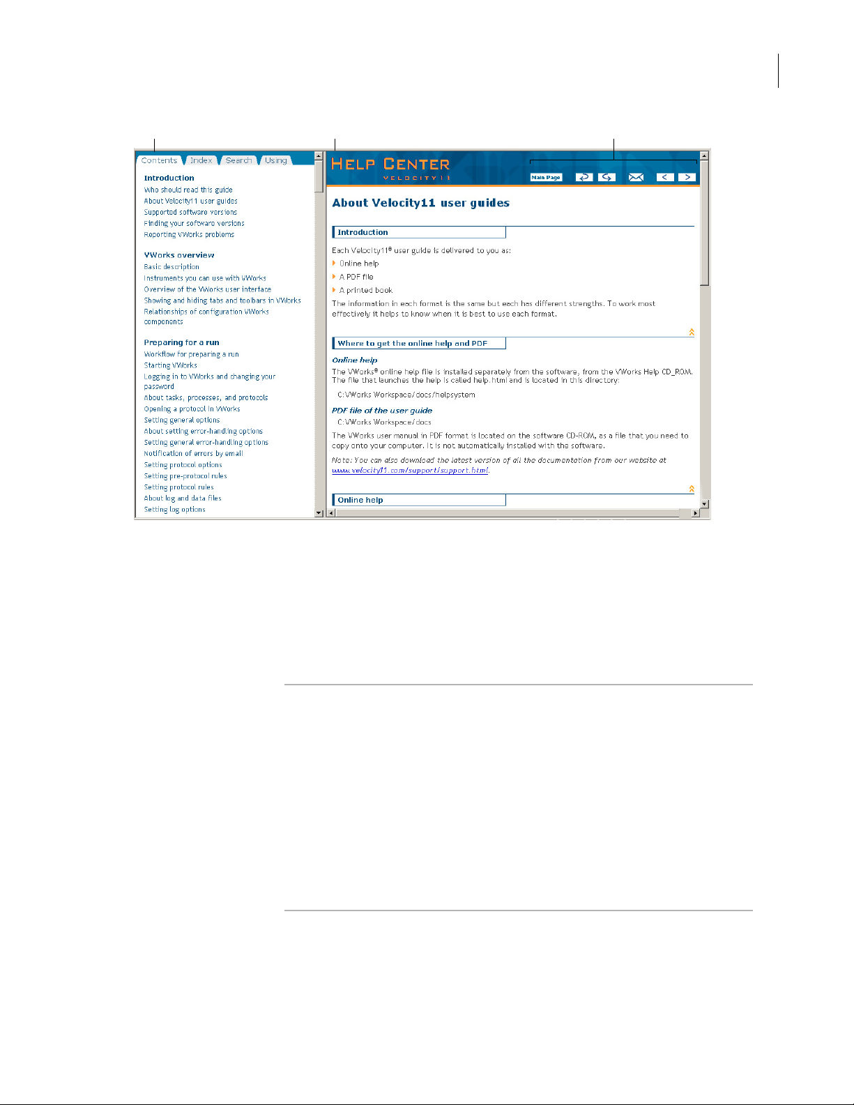
PlateLoc User Guide
Navigation pane Content pane Navigation buttons
Preface
ix
The navi gati on pane has four tabs. The Contents, Inde x , and Search ta bs
provide different ways to locate information. The Using tab contains
information about using the help system.
The content pane displays the online help topics.
Navigation buttons in the content pane allow you to navigate through
the pages.
PDF user guide Computer requirements
To open a user guide in PDF format, you need a PDF viewer. You can
download a free PDF viewer from the internet.
Printing and searching
We provide user guides in PDF format mainly for printing additional
copies. You can use them for simple searches, although these searches
are much slower than online help searches.
More information
For more information about using PDF documents, see the user
documentation for the PDF viewer.

x
Preface
PlateLoc User Guide
Related topics
For more information about... See...
Who should read this guide “Who should read this guide” on
page iv
What this guide covers “What this guide covers” on page v
What’s new in this revision of the
user guide
“What’s new in this user guide” on
page v ii

PlateLoc introduction
This chapter contains the following topics:
❑ “Description of the PlateLoc” on page 2
❑ “Hardware overview” on page 4
❑ “Connection panel” on page 7
❑ “Plate requirements” on page 9
❑ “Inserts” on page 10
❑ “Seal material” on page 13
Chapter 1: PlateLoc introduction
PlateLoc User Guide
1
1
❑ “Lab automation system software” on pa ge 14
❑ “PlateLoc workflows” on page 16
❑ “Safety infor m ation” on page 18

2
Chapter 1: PlateLoc introduction
PlateLoc User Guide
Description of the PlateLoc
About this topic This topic describes the PlateLoc an d explains its uses.
Description The PlateLoc Thermal Plate Sealer is available in two models:
❑ PlateLoc. The PlateLoc is a device that applies seal material on top of
microplates (plates) to seal individual wells. Sealing the wells
protects the contents from evaporation, condensation, and crosscontamination duri n g transport or storage.
❑ Gas-Purging PlateLoc. In addition to the plate-sealing function of the
origina l PlateLoc, the Gas-Purging PlateLoc uses argon gas to
displace air, containing moisture and oxygen, in the plate
immediately before the sealing begins. Because argon is inert, it
does not react with the plate contents. The plate contents can be
protected from hydration and oxidation for up to 24 hours.
Typ i cal ly us e d fo r c o mpo und stor age ap p lic at ion s , the G a s -Pu rgin g
PlateLoc is best for plate contents that are sensitive to oxidation and
moisture (for example, DMSO).
Ways to use the
PlateLoc
Note: For typical polystyrene and polypropylene plates, th e gaspurging effects can last up to 24 hour s when the plates are stored
at room temperature. The effects can las t long er if th e plates are
stored at lower temperatures.
The PlateLoc can be used in the following ways:
❑ As a standalone device
❑ In a Velocity11 lab automation system
❑ In another company’s lab aut omation system
As a standalone device
You can set up the PlateLoc as a standalone device, operating the
PlateLoc from the built-in touch screen. You do not need to connect the
device to a computer.
Using the PlateLoc in the standalone mode allows you to manually load
and seal one plate at a time (a single seal cycle in one run). The
standalone device cannot automatically load and seal multiple plates in
one run.
In a Velocity 11 lab autom atio n s ystem
You can set up the PlateLoc in a Velocity1 1 lab automation system such
as the BenchCel or the BioCel. To install the PlateLoc in the system, you
must connect the device to the controlling computer. You can operate
the inte grated device using the software supplied with the lab
automation system , such as Be nch Works or VWorks. Integr ate d Pla te Loc
operation allows you to automate the loading and sealing of multiple
plates in one protocol run (multiple seal cycles in one run).

Related topics
Chapter 1: PlateLoc introduction
PlateLoc User Guide
In a third-party lab automation system
You can set up the PlateLoc in a third-p ar ty lab automation system. To
install the PlateLoc in the system, you must connect the device to the
cont rolling co mputer. You c an op e r ate the in t e gr ated Pla t eL oc using th e
third-party software. The integrated PlateLoc allows you to automate the
loading and sealing of multiple plates in one run.
Note: Communication between the third-party system and the PlateLoc
is achieved through th e use of ActiveX controls.
For more information about... See...
PlateLoc physical dimensions “Meeting Lab requirements” on page 23
Installing the PlateLoc “Unpacking and installation” on
page 21
3
How to use the PlateLoc as a
standalone device
Setting up the PlateLoc in a lab
automation system
How to use the PlateLoc in a lab
automation system
“Standalone device workflow” on
page 16
❑ “Lab automation system software”
on page 14
❑ “Integrating the PlateLoc into third-
party systems” on page 99
“Lab automation system workflow” on
page 17
4
Chapter 1: PlateLoc introduction
PlateLoc User Guide
Hardware overview
About this topic This topic provides an overview of the PlateLoc hardware features.
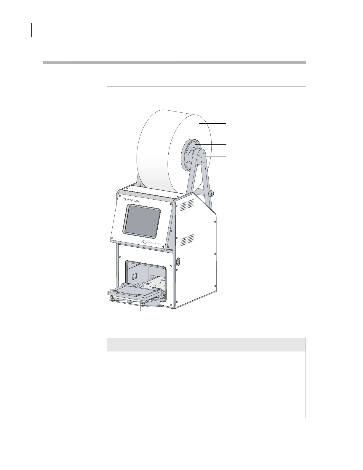
Front features The following diagram shows the front of the PlateLoc. The table below
describes the fe atures shown in the di agram.
Roll of seal
Hub
Seal roll supports
Touch screen
Screen release lever
Sealing chamber
Plate stage
Plate-stage support
Door (opened)
Feature Description
Roll of seal The seal material.
Hubs The structures (together with the axle, not shown) that
hold the roll of seal and allow the roll to rotate.
Seal-roll sup po rt s The structure on which you mount the hubs and a xle.
Touch screen The interface that allows you to specify sealing
parameters, start and stop the seal cycle, and monitor
the seal cycle for standalone operation.
Chapter 1: PlateLoc introduction
PlateLoc User Guide
Feature Description
Sealing chamber The area inside the device where plates are sealed.
Plate stage The removable metal platform on which plates are
loaded.
Door The movable structure that opens when the plate stage is
extended and closes when the stage enters the chamber.
5
Plate-stage
support
The structure on which you load the plate stage. The
plate-stage support extends when the door opens and
retracts when the door closes.
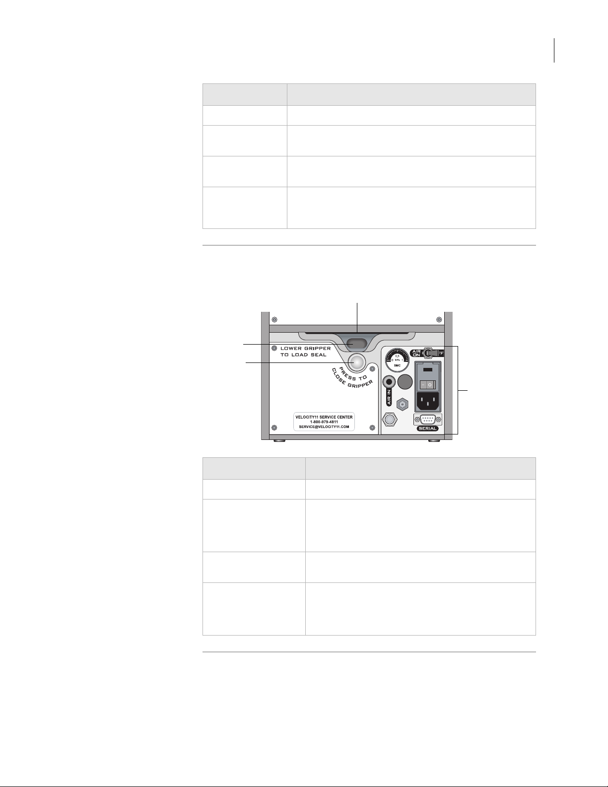
Rear features The following diagram shows the lower back side of the PlateLoc. The
table below it describes the features shown in the diagram.
Seal entry slot
Open-gripper button
Close-gripper button
00191
00191
PlateLoc
PlateLoc
connections
connections
Feature Description
Connection panel
Seal entry slot The narrow opening into which you insert the seal.
Open-gripper button The oval button that you push downward when
inserting the seal into the seal entry slot. Pushing the
button downward opens the grippi ng mechanism
that holds the seal in position.
Close-gripper button The silver button that you press to close the seal-
gripping mechanism.
Connection panel The area where you connect the power, air tubing,
argon tubing (Gas-Purging PlateLocs only), and
computer. The panel also contains a gauge that
allows you to verify air flow.

6
Chapter 1: PlateLoc introduction
PlateLoc User Guide
Related topics
For more information about... See...
The connection panel “Connection panel” on page 7
The PlateLoc physical dimensions “Meeting Lab requirements” on page 23
Installing the PlateLoc “Unpacking and installation” on
page 21
Installing and operating the
PlateLoc
“PlateLoc workflows” on page 16
Chapter 1: PlateLoc introduction
PlateLoc User Guide
Connection panel
About this topic This topic describes the connection pane l on the back of the Pla teLoc.
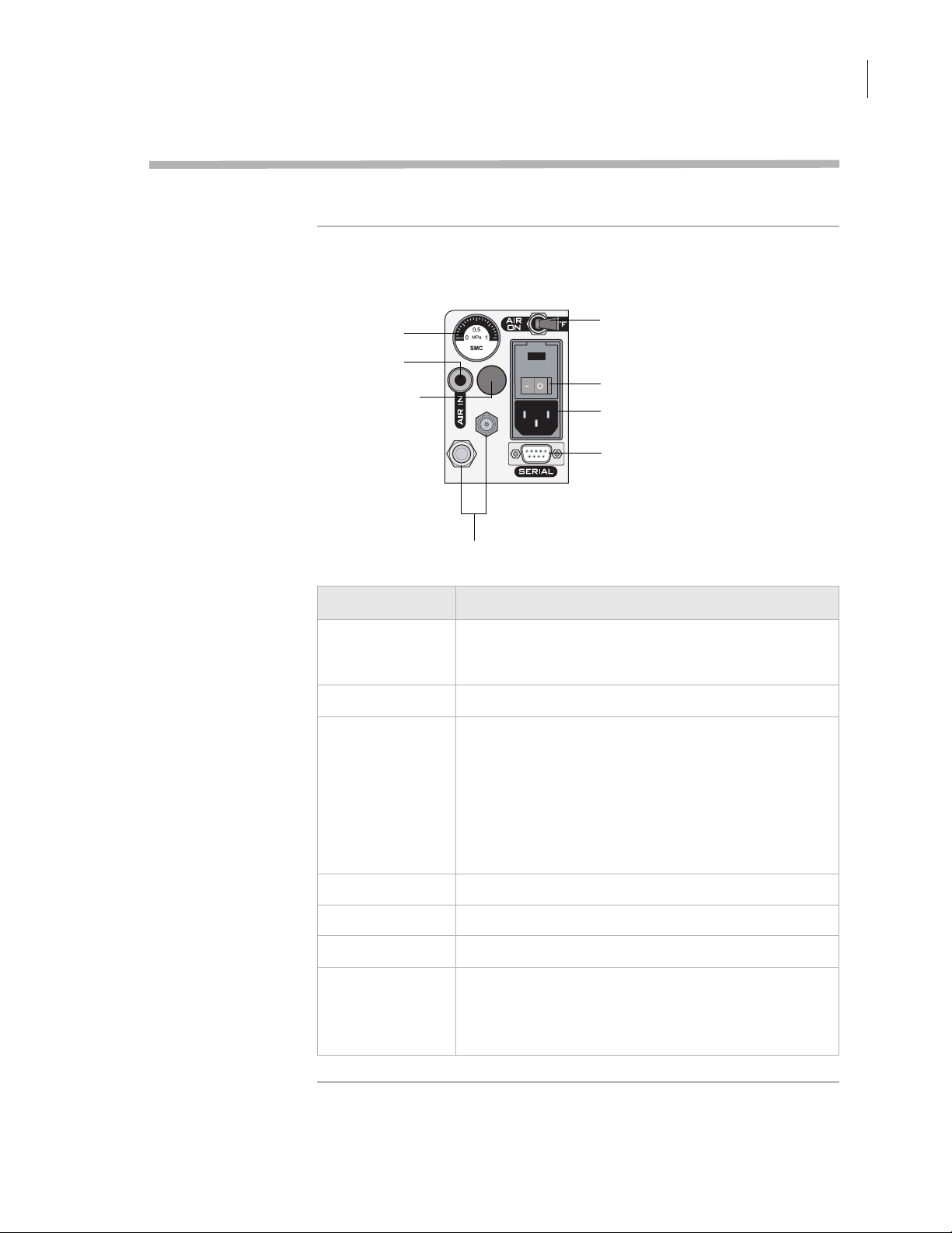
Description The following diagram shows the connection panel that is located on
the back of the PlateLoc. The table below the diagram describes each
component on th e panel.
7
Air flow gauge
Air-input fitting
Argon-input fitting
(Gas-Purging
PlateLocs only)
For Velocity11 service use only
Air on/off switch
Power switch
AC power entry
Serial port
Feature Description
Air flow gauge Indicates the presence of air flow inside the PlateLoc.
Compressed air is used to move pneumatic
components inside the PlateLoc.
Air-input fitting Connects the air tubing to the PlateLoc.
Argon-inpu t fitting
(Gas-Purging
PlateLocs only)
Connects the argon tubing to the G as-Purging PlateLoc.
Argon is used to displace air in the plate, thereby
removing oxygen and moisture.
Note: T here is no on/off switch for argon. Argon starts to
fill the sealing chamber automatically when a seal cycle
starts. For safety reasons, the argon stops filling the
sealing chamber automatically just before the seal is
applied.
Air on/off switch Turns on or off the air flow into the PlateLoc.
Power switch Turns on or off the power to the PlateLoc.
AC power entry Connects the power cord to the PlateLoc.
Serial port Connects the serial cable from the controlling computer
to the PlateLoc.
Use this port when installing the PlateLoc in a lab
automation system.

8
Chapter 1: PlateLoc introduction
PlateLoc User Guide
Related topics
For more information about... See...
Installing and operating the
PlateLoc
“PlateLoc workflows” on page 16

Chapter 1: PlateLoc introduction
PlateLoc User Guide
Plate requirements
About this topic This topic explains the requirements for the plates you can use in the
PlateLoc.
Acceptable plates The PlateLoc accepts plates made from a variety of materials. For a
complete list of the acceptab l e mate rials, see the PlateLoc Thermal Plate
Sealer Seal Selection Guide. You can locate the guide on the Velocity11
website at www.velocity11.com.
Use only plates tha t meet the standards established by the Society of
Biomolecular Sciences (SBS), including deep-well, PCR, and standard
plates in the 96-well, 384-well, and 1536-well formats. For the latest plate
standards, go to www.sbsonline.org. You can also contact the labware
manufacturer to inquire about SBS-standard plates.
Ideal seal cond itions can depend on the plate design, such as thickness
and geometry. For example, plates with raised chimneys that have flat
surfaces at the top can minimize cross-contamination, reduce
evaporation, and minimize condensation.
9
Note: Plates made from the same material but have different designs can
require different sealing parameters.
Velocity11 recommends that you run optimization tests to determine the
best sealing pa ramet e r s to use for each plate type. See “Optim iz in g sea l
quality” on page 77 for some opti mization test guidelines.
Challenging plates Because of the material or design, the f oll owing plat es might cause poor
seal results when used in the PlateLoc:
❑ Plates that have non-binding coatings
❑ Flexible plates that tend to bend during sealing
❑ Breiner Model 651182, 96-well V-bottom plates (when used with the
Velocity11 Peelable Aluminum Seal, 06643.001)
You should run some seali ng tests to d etermine w h ether optimal sealing
is possible with these plates or if you should use different plate types.
See “Optimizing seal quality” on page 77 for some optimization test
guidelines.
Related topics
For more information about... See...
Optimizing seal quality “Optimizing seal quality” on page 77
Inserts (plate supports) “Inserts” on page 10
Seal material “Seal material” on page 13
10
Chapter 1: PlateLoc introduction
PlateLoc User Guide
Inserts
About this topic This topic describes inserts and their uses in the PlateLoc.
What are inserts Inserts are pads that support the bottoms of plates f or uniform seals. You
use inserts to support plates that tend to bend during a seal cycle.
When to use inserts Causes of non-uniform seals
During the seal cycle, a heated m etal plate (hot plate) inside the sealing
chamber descends and presses the seal onto the plate. In a quality seal,
the seal material is applied to the plate uniformly. However, the
following factors can cause u neven plate sealing:
❑ Because of the material used, some plates tend to bend in the high-
temperature environment.
❑ In some plate designs, the plate skirt sits higher or lower than the
plate bottom, causing uneven sealing.
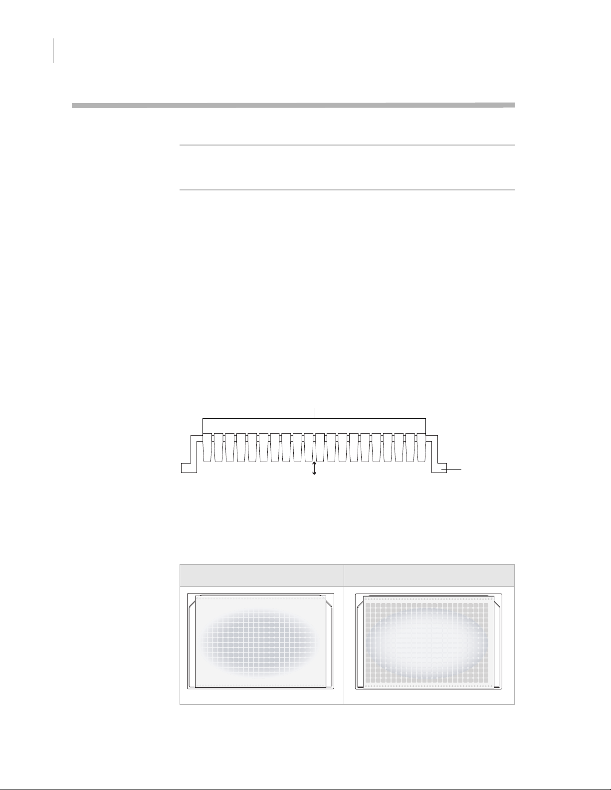
The following diagram shows the side profile of a plate. In this example,
the plate skirt extends past the bottom of the wells. Depending on the
plate ma ter ial, such pl at e desig ns can cause non-uniform sealing. When
the hot plate presses down, the wells at the center of the plate might
bend upward or downward.
Wells
Skirt
Bending movement
The following diagrams show the top view of sealed plates. Non-uniform
seals can result when the center of the plate bends upward (left) and
downward (right) during the seal cycle.
Plate center is higher Plate center is too low
00200
PlateLoc
shim too high
00200
00199
PlateLoc
shim too low
00199
Chapter 1: PlateLoc introduction
PlateLoc User Guide
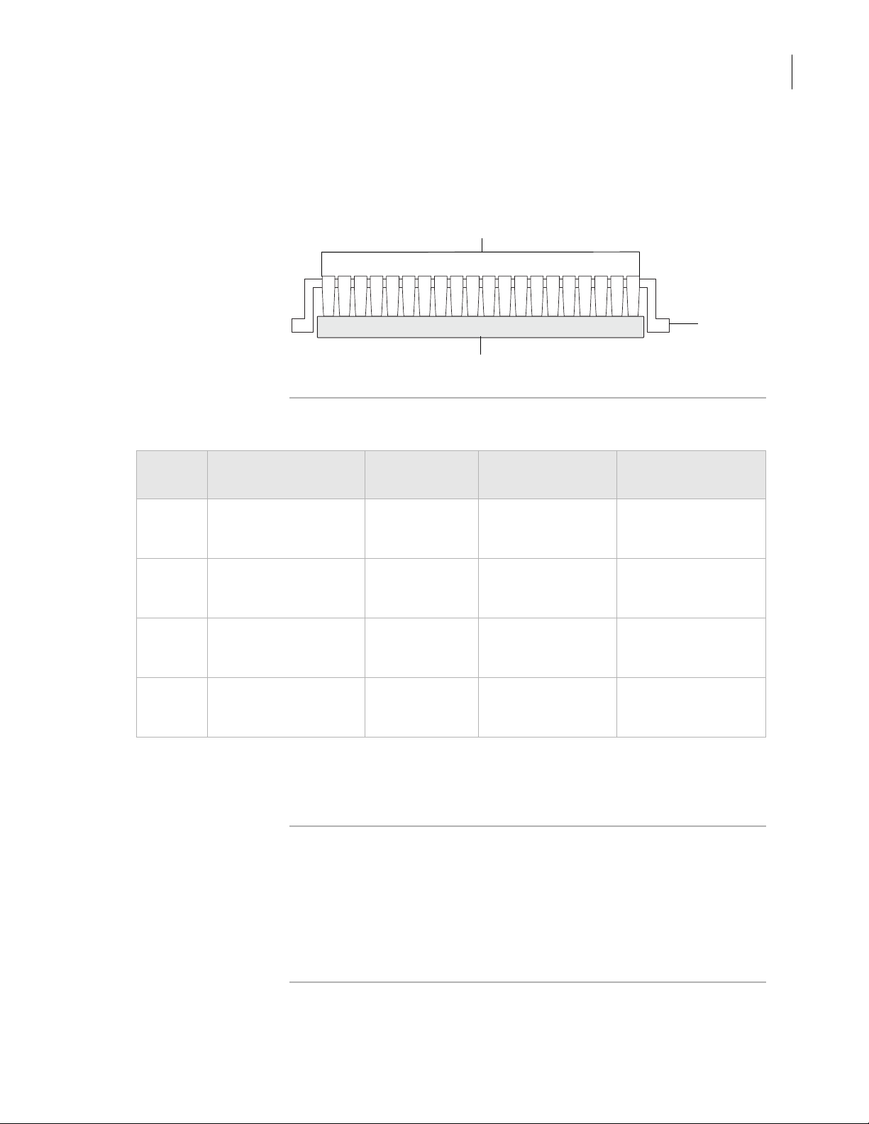
Using inserts to suppo rt plates
For plates that tend to bend or do not li e flat during the seal cycle, you
can place an insert under the plate to provide equal support under
every well. The following diagram shows an insert supporting the wells
for uniform sea lin g.
Wells
Skirt
Insert
11
Inserts suppli ed with
The following table lists the inserts that are supplied with the PlateLoc.
the PlateLoc
Insert Description Thickness Height above plate
stage support
90 Metal pad with rubber
foam padding on the
plate-facing side
180 Metal pad 4.60 mm
235 Metal pad 6.00 mm
290 Metal pad 7.37 mm
8.65 mm
(0.340 in)
(0.180 in)
(0.235 in)
(0.290 in)
4 mm (0.2 in) Plates that require
0
mm (0 in)
1.4 mm (0.055 in) Plates that require
2.8 mm (0.11 in) Plates that require
Other types of inserts are available. For a complete list of available
inserts, see the PlateLoc Thermal Plate Sealer Seal Selection Guide. You
can locate the guide on the Velocity11 website at www.velocity11.com.
Use with...
flexible support
Plates that require
non-flexible support
under the wells
non-flexible support
under the wells
non-flexible support
under the wells
Insert selection The type of insert you use depends on the plate material and plate
design. Velocity11 recommends that you run optimization tests to
determine the best insert for the plate you are using. See “Optimizing
seal quality” on page 77 for some optimization test guidelines.
For insert selection guidelines and starting parameters to use, se e the
PlateLoc Thermal Plate Sealer Seal Selection Guide. You can locate the
guide on the Velocity11 website at www.velocity11.com.

12
Chapter 1: PlateLoc introduction
PlateLoc User Guide
Related topics
For more information about... See...
Optimizing seal quality “Optimizing seal quality” on page 77
Plate requirements “Plate requirements” on page 9
Seal material “Seal material” on page 13

Chapter 1: PlateLoc introduction
PlateLoc User Guide
Seal material
About this topic This topic explains the types of seal material that are available and the
factors that might affect seal quality.
13
Seal supplied with
the PlateLoc
A roll of se al is supplied with the Plate Loc. To ensure optimal seal
quality, Velocity11 recommends that you run optimization tests to
determine the best sealing parameters to use for each plate type and
application.
Selecting o ther seals !! DAMAGE HA ZARD !! Use only Velocity11 seals with the
PlateLoc. Seals from another manufacturer might not seal properly
in the PlateLoc and can damage the device.
Velocity11 offers a variety of seals with different properties, including:
❑ Clear seals. Allows you t o see the contents of the plate.
❑ Aluminum seals. Protects light-sensitiv e samples or compounds in
the plate.
❑ Pe elable seals. Allows you to peel the seal off the plate in a
downstream task.
❑ Non-pierceable seals. Protects the plate contents from accidental
piercing.
The type of seal you can use depends on a number of factors, including:
❑ Plat e material
❑ Plate design
❑ Plate properties (for example, optical and physical properties)
Related topics
❑ Plate contents (samples, reagents, and so on)
❑ Application (for example, PCR, DNA sequencing, compound
storage, and so on)
❑ Storage duration and conditions
For a complete list of seals and selection guidelines, see the PlateLo c
Thermal Plate Sealer Seal Selection Guide. You can locate the guide on
the Velocity11 website at www.velocity11.com.
Velocity11 recommends that you run optimization tests to determine the
best seals to use. See “Optimizing seal quality” on page 77 for some test
guidelines.
For more information about... See...
Plate requirements “Plate requirements” on page 9
Inserts (plate supports) “Inserts” on page 10
Optimizing seal quality “Optimizing seal quality” on page 77

14
Chapter 1: PlateLoc introduction
PlateLoc User Guide
Lab automation system software
About this topic This topic describes the software you use to set up and control the
PlateLoc in a Velocity11 lab automation sy st em. For information about
integrating the PlateLoc in a third-party lab automation system, see
“Integrating the PlateLoc into third-party systems” on page 99.
Note: You do not need to read this topic if you are using the PlateLoc as
a standalone device.
Lab automation
requirements
Lab automation
system software
In a lab automation system, you can use a plate-loading robot to
automate the sealing of multiple plates. You use the lab automation
system software to se t up the communication between the system and
the PlateLoc, set up the sealing parameters, and control the automation.
Velocity11 provides lab automation platforms, including the BenchCel
and the BioCel plate-handling systems. You can install the PlateLoc in
these systems to automate the multiple-plate sealing process.
You use the Velocity11 lab auto mation system software, such as
BenchWorks and VWorks, to control the PlateLoc in the system. The
software allows you to:
❑ Create protocols. Protocols determine the sequence of tasks you
want to automate in a run. For example, you can use a protocol to
seal 10 plates in one protocol run.
❑ Set PlateLoc task parameters. The task parameters specify the sealing
temperature and duration for a multiple-plate run.
❑ Start and stop a run. You can st art and s t op t he pr ot oc ol run from the
controlling co mputer.
PlateLoc Diagnostics PlateLoc Diagnostics is a component of the supplied PlateLoc ActiveX
software that enables integration with a lab automation system.
Accessed through the Velocity11 lab automation system software, such
as BenchWorks and VWorks, PlateLoc Diagnostics allows you to:
❑ Create profiles. Profiles allow you to set up communication with the
lab automation system software and set default sealing parameter
values.
❑ Manually set up and run the PlateLoc. This is equivalent to setting up
and running the device from the touch screen. Use the manual
adjustments and controls t o run a single plate for diagnostic use
only.
❑ Check the odometer. The odometer indicates the number of sealing
cycl es the device has performed. You can refer to this value for
preventive maintenance purposes.

Related topics
For more information about... See...
Chapter 1: PlateLoc introduction
PlateLoc User Guide
15
Operating the PlateLoc in a lab
automation system
Creating and managing Plate Loc
profiles
“Lab automation system workflow” on
page 17
“Creating and managing profiles (lab
automation systems only)” on page 59
Creating and managing protocols Velocity11 lab automation software user
guide, such as the VWorks User Guide
Setting PlateLoc task parameters Velocity11 lab automation software user
guide, such as the VWorks User Guide
Starting and stopping the protocol
run
Using ActiveX control to configure
third-party lab automation
Velocity11 lab automation software user
guide, such as the VWorks User Guide
“Integrating the PlateLoc into third-
party systems” on page 99
software to interface with the
PlateLoc

16
Chapter 1: PlateLoc introduction
PlateLoc User Guide
PlateLoc workflows
About this topic This topic presents the workflows for operating the PlateLoc as a
standalone device and in a Velocity11 lab automation system.
Standalone device
workflow
The following table presents the basic steps for operating the PlateLoc as
a standalone device. When optimizing the seal quality, repeat steps 6
through 8.
Step Procedure See...
1 Turn on the PlateLoc. “Turning on and turning off the
power” on page 42
2 Turn on the air. “Turning on and turning off the
air” on page 44
3 Gas-Purging PlateLocs only. Turn
on the argon.
4 Adjust the touchscreen.
“Turning on and turning off the
argon (Gas-Purging Platelocs
only)” on page 47
❑ “Tilting and stowing the
touch screen” on page 49
❑ “Adjusting the touch screen
contrast” on page 51
5 Load the seal. “Loading and unloading a roll of
seal” on page 53
6 Set the sealing parameter s. “Setting the sealing parameters”
on page 68
7 Load an insert and a plate. “Loading an insert and a plate”
on page 66
8 Start the seal cycle. “Starting the seal cycle” on
page 72

Chapter 1: PlateLoc introduction
PlateLoc User Guide
17
Lab automation
system wor k flow
The following table presents the basic steps for operating the PlateLoc in
a Velocity11 lab automation system. When optimizing the seal quality,
repeat steps 8 through 9.
Note: The steps for installing and operating the PlateLoc in a third-party
lab automation system might differ. For details, refer to the third-party
user documenta tion.
Step Procedure See...
1 Turn on the PlateLoc. “Turning on and turning off the
power” on page 42
2 Turn on the air. “Turning on and turning off the
air” on page 44
3 Gas-Purging PlateLoc only. Turn
on the argon.
4 Option al. Adjust the touchscreen.
“Turning on and turning off the
argon (Gas-Purging Platelocs
only)” on page 47
❑ “Tilting and stowing the
touch screen” on page 49
❑ “Adjusting the touch screen
contrast” on page 51
5 Load the seal. “Loading and unloading a roll of
seal” on page 53
Related topics
6 Create PlateLoc profiles. “Creating and managing profiles
(lab automation systems only)”
on page 59
7 Establish communication with
the PlateLoc.
8 Create protocols and set task
parameters.
9 Star t the protocol run (seal
cycles).
For more information about... See...
Workflow for i ns talling and
operating the PlateLoc in a thirdparty automation system
Using ActiveX control to configure
third-party lab automation
software to interface with the
PlateLoc
“Establishing communications
with the PlateLoc (lab
automation systems only)” on
page 62
Velocity11 l ab automa tion s ystem
software user guide, such as the
VWorks User Guide
“Starting the seal cycle” on
page 72
The third-party product d ocumentation
“Integrating the PlateLoc into third-
party systems” on page 99

18
Chapter 1: PlateLoc introduction
PlateLoc User Guide
Safety information
About this topic This topic provides information for the safe operation of the PlateLoc.
Before using the
PlateLoc
Before using the PlateLoc, your organization should make sure that you
are properly trained in:
❑ General laboratory safety
❑ The correct and safe operation of the PlateLoc
❑ The correct and safe operation of lab automation systems or
components used in combination with the PlateLoc
If you are the person in your organization responsible for training others
on the PlateLoc and you have a safety question, contact Velocity11
Technical Support.
Safety standards The PlateLoc is CE certified and complies with the following CE safety
directive: EN 61010-1:1993, safety requirements for electrical equipment
for measurement, control, and laboratory use, including amendments 1
and 2.
The PlateLoc is designed to meet UL specifications.
For the latest compliance information, contact Velocity11 Technical
Support.
Safety labels Pay attention to safety labels on the PlateLoc. A safety label consists of a
warning symbol, a description of the warning, and information that
helps you to avoid the safety hazard.
The following diagram shows the safety lab el that is placed on the front
of the PlateLoc to warn you of high-temperature hazards.
00196
PlateLoc
Front

Chapter 1: PlateLoc introduction
PlateLoc User Guide
General precautions !! INJURY HAZARD !! Do not attempt to remove the PlateLoc
covers and disassemble the device. Doing so can cause injuries and
damage the device.
!! INJURY HAZARD !! Using controls, making adjustments, or
performing procedures othe r than tho se spec i fi ed i n this use r gui de
can expose you to hot surfaces, high pressure gases, and moving
parts. Ex posure to these hazards can cause severe injury.
The PlateLoc is designed for safe operation. Under normal operating
conditions, you are prote c ted from high tempera t ure, high pressu r e , and
moving parts. However, you should be aware of these hazards and
understand how to avoid being exposed to them.
Chemical ha zards !! INJURY HAZARD !! Chemicals that have low flash points (such
as reagents that are used in radioactive scintillation proximity
assays (SPAs) and solvents, including alcohols) must not be used in
the Plat e Lo c .
Some chemicals used when working with the PlateLoc can be
hazardous. Make sure you follow your local, state, and federal safety
regulations when using and disposing of the chemicals.
19
Argon gas (GasPurging Platelocs
only)
Gas cylinders and
pressure regulators
Read the recommendations in the MSDS (Material Safety Data Sheet) for
every chemical that you plan to use. The manufacturer of the chemical
should pr ovide you wi th the MSDS.
!! INJURY HAZARD !! Argon is an odorless, colorless, and
nontoxic gas that can cause rapid suffocation by displacing air.
Argon is heavier than air and can flow into low areas.
Always use argon in a well-ventilated area. Always turn off the argon
source when the PlateLoc is not in use.
You should set up an oxygen monitor in the lab to prevent accidental
suffocation. The oxygen monitor can set off an alarm if the oxygen level
falls below the acceptable threshold.
Follow the local, state, and federal safety codes for the placement and
mounting of gas cylinders. For example, you might have to attach a
standard cylinder bracket to a solid permanent structure to meet or
exceed all local seismic and safety requireme nts.
Always use good lab practices when handling high-pressure cylinders.
Make sure you follow any instructions provided with the cylinders.

20
Chapter 1: PlateLoc introduction
PlateLoc User Guide
High-temperature
hazards
!! INJURY HAZARD !! Do not touch the PlateLoc or pry open the
door while it is in operation. The hot surfaces can cause burn injury.
Use caution when removing a plate after it is sealed. The plate might still
be hot from the sealing process.
Do not reach into the PlateLoc when it is at warmed up to a high
temperature. When cleaning the metal plate (hot plate) inside the
device, make sure the temperature setting does not exceed 40 °C. For
details, see “Cleaning the hot plate” on page 84.
Moving-parts
hazards
The Pla te Loc conta ins mo vi ng parts tha t c an cause injury. Under normal
operating conditions, the PlateLoc is designed to protect you from the
moving parts. The door sensor is designed so that the seal cycle cannot
start unless the door is closed.
!! INJURY HAZARD !!
to acce ss the interior of the device through any other openings.
Exposure to the moving parts, such as the heated metal plate (hot
plate) or the seal-cutting blade can cause severe injurie s.
Do not disable the door sensor or attempt
In an emergency, turn off the Plat eLoc. The on/off switch is located on
the lower back side of the device.
Fuses Contact Velocity11 Customer Service to replace the Pla teLoc fuses. Do
not attempt to re place the fuses you rself.
Product use Velocity11’s products must only be used in the manner described in the
user guid es. Any other use can damage the p roduct or injure you.
Velocity11 is not responsible for damages caused, in whole or part, by
unauthorized modifications, or by procedures that are not explicitly
described in the product user guides. Any modifications or changes to
products not expressl y described in Velocity11 user guides are not
covered under the warran ty.
The PlateLoc is not intended or approved for diagnosis of disease in
humans or animals.
Related topics
For more information about... See...
Hardware description “Hardware overview” on page 4
Connection panel location and
description
Turning on and off the PlateLoc “Turning on and turning off the power”
Stopping the PlateLoc in an
emergency
Cleaning the hot plate “Cleaning the hot plate” on page 84
“Connection panel” on page 7
on page 42
“Stopping a seal cycle in progress” on
page 74

Unpacking and installation
This chapter contains the following topics:
❑ “Installation workflow” on page 22
❑ “Meeting Lab requirements” on page 23
❑ “Unpacking the PlateLoc” on page 27
❑ “Con ne c tin g the power so urce ” on page 30
❑ “Connecting and disconnecting the air source” on page 31
❑ “Connecting and d isconnecting the argon source (Gas-Purg ing
PlateLocs only)” on page 34
Chapter 2: Unpacking and install ation
PlateLoc User Guide
2
21
❑ “Connecting to the controlling computer (lab automation systems
only)” on pag e 37
❑ “Installing the PlateLoc ActiveX software (lab automation systems
only)” on pag e 38

22
Chapter 2: Unpacking and installation
PlateLoc User Guide
Installation workflow
About this topic This topic presents the workflow for unpacking and installing the
PlateLoc as a standalone device and in a Velocity11 lab automation
system.
Workflow The following table presents the workflow for unpacking and installing
the PlateLoc.
Note: If you are using the PlateLoc as a standalone device, skip steps 6
through 8.
Step Procedure See...
1 Prepare your lab for the
installation.
2 Unpack the PlateLoc. “U npacking th e PlateLoc” on
3 Connect the PlateLoc to the
power source.
4 Connect the PlateLoc to the air
source.
5 Gas-Purging PlateLocs only.
Connect the PlateLoc to the
argon source.
6 Lab automation syste ms on ly.
Connect the PlateLoc to the
controlling computer.
7 Lab automation syste ms only.
Install the PlateLoc ActiveX
software.
8 Lab automation syste ms on ly. In
the lab a ut o m ati on sof tware, add
the PlateLoc, and set the
properties for the device.
“Meeting Lab requirements” on
page 23
page 27
“Connecting the power source”
on page 30
“Connecting and disconnecting
the air source” on page 31
“Connecting and disconnecting
the argon source (Gas-Purging
PlateLocs only)” on page 34
“Connecting to the controlling
computer (lab autom atio n
systems only)” on page 37
“Installing the PlateLoc ActiveX
software (lab automation systems
only)” on page 38
Velocity11 l ab automa tion s ystem
software user guide, such as the
VWorks User Guide
Related topics
For more information about... See...
Workflow for i ns talling and
operating the PlateLoc in a thirdparty automation system
Operating the PlateLoc “PlateLoc workflows” on page 16
The third-party product d ocumentation

Chapter 2: Unpacking and install ation
PlateLoc User Guide
Meeting Lab requirements
About this topic This topic describes the requirements for installing the PlateLoc.
Lab space The weight and dimensions of the PlateLoc are as follows:
Dimension Value
23
Weight
Width
Height (with seal moun ted)
Depth (with door open and seal mounted)
21.6 cm (8.50 in)
58.4 cm (23.0 in)
20
21.6
58.4
39.9
39.9
cm (15.7 in)
kg (45 lb)
cm (8.50 in)
cm (23.0 in)
cm (15.7 in)
When planning lab space for the PlateLoc, you should consider the
following:
❑ Make s ure th e la b bench can su pport the w e ight of the P late Loc, and
the surface is level.
❑ Provide ad equate b ench space for the PlateLoc.
❑ Make sure there is sufficient clearance around the PlateLoc so that
you can reach the bac k of the device to turn off the power and air in
an emergency.
❑ Place th e PlateLoc within 1.8 m (6 ft) of the electrical outlets.
❑ Place the PlateLoc within 4.6 m (15 ft) of the air source.
❑ Gas-Purging PlateLocs only. Place the PlateLoc within 4.6 m (15 ft) of
the argon sour ce.

24
Chapter 2: Unpacking and installation
PlateLoc User Guide
❑ Gas-Purging PlateLocs only. Make sure the room is well ventilated
and an oxygen monitor is nearby.
❑ Lab automation system installation only. Check with the lab
automation system manufactur er for installation requirements.
Air sour c e The PlateLoc requires the use of oil-free compressed air to move
pneumatic components inside the device. The oil-free compressed air
can be from the following sources:
❑ Centralized source (house)
❑ Compressed-air cylinders
❑ Portable pumps
!! DAM AGE H AZAR D !!
leak int o the PlateLoc and void your warranty.
Using oil compressors can cause oil to
To maintain the desired air supply in the device, the Pla teLoc requires a
source of air as follows:
Requirement Value
Quality Clean, dry, compressed
Flow rate
Pressure
!! DAM AGE H AZAR D !!
psi) can damage the PlateLoc.
(100
70.8
Lpm (2.50 cfm)
0.62–0.69
Air pressure greater than 0.69 MPa
MPa (90–100 psi)
Environment The lab must meet the following environmental requirements.
Requirement Value
Ambient temperature
Humidity condition
4–40
°C (39–104 °F)
10–90%
RH, non-condensing
Velocity11 recommends that you do the following:
❑ Place the PlateLoc away from heat and air conditioning ducts.
❑ Place the PlateLoc away from direct sunlight.

Chapter 2: Unpacking and install ation
PlateLoc User Guide
Electrical The electrical requirements for the PlateLoc are as follows:
Model
Requirement
N. Ameri c a Europe
Voltage 115~ 230~
25
Argon source (GasPurging PlateLoc
only)
Frequency
Current
!! DAM AGE H AZAR D !!
circuit that is properly grounded.
50–60
Hz 50–60 Hz
A5 A
5
Always connect the PlateLoc to an AC
The Gas-Purging PlateLoc typically uses argon to displace air (oxygen
and moisture) in the plate. The argon can be from a centralized source
(house) or f rom a cylinder.
To maintain the desired argon supply in the device , mak e sure the argon
meets the following requirements:
Requirement Value
Quality 99.9% pure, welding grade, containing up to
ppb water
1
Note: The water content is more important
than the gas grade.
Pressure
!! INJURY HAZARD !!
oxygen monitor nearby to prevent accidental suffocation.
0.28
MPa (40 psi)
For safety re asons, you should install an
Computer If you are installing the PlateLoc in a lab automation system, you must
connect the device to the controlling computer (the computer that has
the lab automation system software i nstalled). You must also install the
PlateLoc Acti veX software to enable the device to interface with the
computer.
The lab automation system computer must meet the following minimum
requirements to interface with the PlateLoc:
❑ Pentium 3
❑ 256 MB RAM
❑ Windows 2000 or Windows XP
❑ 10 MB free disk space
❑ RS-232 DB9 serial port
For lab automation system requirements, see the Velocity11 lab
automation syst em softw ar e user guide o r the thir d-party la b automa tion
system software user documentation.

26
Chapter 2: Unpacking and installation
PlateLoc User Guide
Related topics
For more information about... See...
How to use the PlateLoc as a
standalone device
Setting up the PlateLoc in a lab
automation system
How to use the PlateLoc in a lab
automation system
“Standalone device workflow” on
page 16
❑ “Lab automation system software”
on page 14
❑ “Integrating the PlateLoc into third-
party systems” on page 99
“Lab automation system workflow” on
page 17

Chapter 2: Unpacking and install ation
Unpacking t he PlateLoc
About this topic This topic explains how to unpack the PlateLoc.
PlateLoc User Guide
27
Unpacking
precautions
Unpacking the
PlateLoc from its
shipping containe r
When unpacking the PlateLoc, be sure to:
❑ Note the dimensions of the shipping container before moving it to
make sure you have adequate clearance through doorways and
passages.
❑ Make sure the final location is nearby and easily accessible.
❑ Use care when lifting the PlateLoc to prevent perso nal inju ry and
damage to the device. The PlateLoc weighs 20 kg (45 lb) and might
require two people to lift it.
The PlateLoc and its components are shipped in two shipping
containers:
❑ The Plat eLoc con tainer. Contains the main body of the device and all
the items you need to install and operate the PlateLoc.
❑ The seal roll container. Contains a roll of seal.
To unpack the PlateLoc and the roll o f seal:
1. Open the top of the PlateLoc co nta iner.
2. Remove the thin layer of packing foam.
3. Remove the inner box and set it aside.
4. Carefully lift the PlateLoc out of the shipping container.
5. Remove the packing foams on the left and right sides of the device.
6. Remove the PlateLoc from the plastic bag and set it carefully on the
lab bench or final location where you want to install the device.
Note: A small block of foam p ieces is p acked inside t he PlateLoc.
You will remove the packing foam after you install the device and
turn on the air.
7. Open the inner box and remove the components from the box.
8. Open the seal roll container, remove the roll of seal, and remove the
seal from the plastic bag.
!! IMPORTANT !!
container in case you need to move or ship the PlateLoc.
!! DAM AGE H AZAR D !! The packing materials and shipping
containe r we re des ign ed to p rotec t th e dev i ce. Pa ckin g the P lateLoc
using other materials and containers can damage the device and
void your warranty.
Save the packing materials and shipp in g

28
Chapter 2: Unpacking and installation
PlateLoc User Guide
Inspecting the
contents
PlateLoc c ompon ents
After you unpack the PlateLoc and seal, check that you have the items
shown in the fol lowing diagram.
Hubs and axle
090
180
235
290
Inserts
Roll of seal
Plate stage
PlateLoc Thermal Plate Sealer
Air tubing Power cord
Seal-loading card PlateLoc User Guide
Fitting union tee
and NPT fittings
RS-232 DB9 serial cable
Metric fittings:
Union tee, adaptor, tube
ActiveX CD

Chapter 2: Unpacking and install ation
PlateLoc User Guide
Additional components for the Gas-Purging PlateLoc
If you ha ve the Gas-Purging PlateLoc, chec k that y ou hav e all the items in
the previous diagram and the items in the following diagram.
Argon tubing
or
29
Related topics
Fitting union tee
and NPT fittings
Metric fittings:
Union tee, adaptor, tube
Missing or damaged items
Inspect the items to make sure you ha ve everything listed and there is no
damage. If any of the items are missing or damaged, contact Velocity11
Technical Support.
For more information about... See...
Removing the packing foam inside
the PlateLoc
How to use the PlateLoc as a
standalone device
Setting up the PlateLoc in a lab
automation system
“Turning on and turning off the air” on
page 44
“Standalone device workflow” on
page 16
❑ “Lab automation system software”
on page 14
❑ “Integrating the PlateLoc into third-
party systems” on page 99
How to use the PlateLoc in a lab
automation system
“Lab automation system workflow” on
page 17

30
Chapter 2: Unpacking and installation
PlateLoc User Guide
Connecti ng the power source
About this topic This topic explains how to connect the PlateLoc to a grounded po wer
source.
Before you sta r t Make sure you have the supplied power cord.
Procedure To connect the power cord:
1. Plug one end of the power cord into the AC power entry located on
the back of the PlateLoc.
2. Plug the other end of the cord into an AC outlet with a grounded
circuit.
Related topics
00191
00191
PlateLoc
PlateLoc
connections
connections
For more information about... See...
Installation and operating
“Meeting Lab requirements” on page 23
requirements
To AC outlet with
grounded circuit

Chapter 2: Unpacking and install ation
PlateLoc User Guide
Connecti ng and disconnecting the air source
About this topic Compressed air is used to move pneumatic components inside the
PlateLoc. This topic explains how to connect the PlateLoc to the air
source and check the connections for leaks before use.
Before you sta r t Make sure you ha ve the following:
❑ Air tubing (supplied)
❑ NPT or metric fitting adaptor (supplied)
31
Connecting the air
source
To conn ect the PlateLoc to your air source:
1. Turn off the air at the source (house, cylinder, or pump).
2. Attach the following adaptor fittings to the air source connection if
necessary:
NPT fitting. If your air source uses a threaded connection, attach
the supplie d 1/4 -inc h o r 1/8 -in NPT fitt ing t o the conne ctio n. Th e
NPT fitting is threaded on one end and has a quick-release fitting
on the ot her end.
Metric fittings adaptor . If your lab requires metric fitti ngs at th e air
source, attach the supplied 1/4-inch metric adaptor fitting to the
air source connection. The metric adaptor fitting has a quickrelease fitting on one end.
3. Connect one end of the air tubing to the air source (house, cylinder,
or pump), and then connect the free end of the tubing to the quick
disconnect fitting at the air-input (AIR IN) port.
To connect the tubing, push the end of the tubing into the quick
disconnect fitting at the air source and on the back of the PlateLoc.
The following diagram shows the air tubing connection on the back
of the PlateLoc .
00191
00191
PlateLoc
PlateLoc
connections
connections
To air source (house,
cylinder, or pump)

32
Chapter 2: Unpacking and installation
PlateLoc User Guide
Checking the air
connections
Disconnecting the
air source
To check the air connections:
1. With the air source turned off, gently tug the air tubing at each
connection.
If you f e el r esistance a t the co nn ect i on, the t u b ing has been p r o perly
installed.
2. Tu r n on th e air so urce.
3. Listen near each connection for hissing sounds that might indicate a
leak.
If you hear hissing sounds, turn off the air at the source and on the
back of the Plate Loc, check and tighten the connections, and then
turn on the air again. If the problem persists, contact your facilities
department or Velocity11 Technical Support.
!! DAM AGE H AZAR D !! Do not pull the tubing out of the orange
quick disconnect fitting. Doing so can damage the fitting.
To disconnect the air tubing from the P lateLoc:
1. Turn off the air at the source (house, cylinder, or pump).
2. Turn off the air on the back of the PlateLoc.
3. Push and hold the locking collar against the fitting, and then gently
pull the air tubing out.
Note: Altern atively, you can use the SMC Pn eu matics tool (TG- 2)
to aid in this task. See th e manufacturer’s documentation for use
instructio ns. Co nt act your loc al SMC parts s u pplier for o rder ing
details.
The following diagram shows a close-up view of the quick
disconnect fitting.
Push and hold the locking collar.
Gently pull out the tubing.

Related topics
Chapter 2: Unpacking and install ation
PlateLoc User Guide
For more information about... See...
Air source requirements “Meeting Lab requirements” on page 23
33
Components for connecting the
PlateLoc to the air source
Air-input fitting on the connection
panel
“Inspecting the contents” on page 28
“Connection panel” on page 7

34
Chapter 2: Unpacking and installation
PlateLoc User Guide
Connecting and disconnecting the argon source (Gas-Purging PlateLocs only)
About this topic This topic explains how to connect the PlateLoc to the argon source.
Read this topic only if you have a Gas-Purging PlateLoc.
Before you sta r t !! INJURY HAZARD !! Make sure the area in wh ich you are
working is well ventilated and you have installed an oxygen
monitor nearby. Argon can cause rapid suffocation by displacing
air. Argon is heavier than air and can flow into low areas.
Make sure you ha ve the following:
❑ Argon tubing (supplied)
❑ NPT or metric adaptor fitting (supplied)
Connecting the
argon source
To conn ect the PlateLoc to your ar gon source:
1. Turn off the argon source (house or cylinder).
2. Attach the fol lo wing adap tor fit tings to the arg on sou rce if necessary:
NPT fitting. If your argon source uses a threaded connection,
attach the suppli ed 1/4-inch or 1/8-in NPT fitting to the
connection. The NPT fitting is threade d o n one end and has a
quick-release fitting on the other end.
Metri c fittings adap tor. If your lab requires metric fittings at the
argo n s ource, attach the supplied 1/4-inch metric adaptor fitting
to the argon s ource connection. The metric adaptor fitting has a
quick-release fitti ng on one end.
3. Connect one end of an argon tubing to the argon source, and then
connect the free end of that tubing to the quick disconnect fitting at
the argon-input port.
To connect the tubing, push the end of the tubing into the quick
disconnect fitting at the argon source and at the back of the
PlateLoc.
!! DAM AGE H AZAR D !!
the air- input (AIR IN) fitting. Doing so can cause errors w hen
you ope rat e th e PlateLoc.
The following diagram shows the connect ion from the back of the
PlateLoc to the argon source.
Do not connect the argon tubing to

00191
00191
PlateLoc
PlateLoc
connections
connections
Chapter 2: Unpacking and install ation
PlateLoc User Guide
To argon source
(house or cylinder)
35
Checking the argon
connections
Disconnecting the
argon source
!! INJURY HAZARD !! Argon is an odorless, colorless, and
nontoxic gas that can cause rapid suffocation by displacing air.
Argon is h eav ier tha n air a nd can f lo w in to lo w a reas. Make su re t he
oxygen monitor is turned on.
To check the argon connection:
1. With the PlateLoc turned off, gently tug the argon tubing at each
connection.
If you f e el r esistance a t the co nn ect i on, the t u b ing has been p r o perly
installed.
2. Turn on the argon source.
3. Listen near each connection for hissing sounds that might indicate a
leak.
If you hear hissing sounds, turn off the argon at the source, tighten
the connections, and then turn on the argon again. If the problem
persists, contact your facilities department or Velocity11 Technical
Support.
!! DAM AGE H AZAR D !! Do not pull the tubing out of the orange
quick disconnect fitting. Doing so can damage the fitting.
To disconnect the argon tubing from the PlateLoc:
1. Turn off the argon at the source (house or cy linder).
2. Push and hold the locking collar against the fitting, and then gently
pull the argon tubing out.
Note: Altern atively, you can use the SMC Pn eu matics tool (TG- 2)
to aid in this task. See th e manufacturer’s documentation for use
instructio ns. Co nt act your loc al SMC parts s u pplier for o rder ing
details.

36
Chapter 2: Unpacking and installation
PlateLoc User Guide
The following diagram shows a close-up view of the quick
disconnect fitting.
Push and hold the locking collar.
Gently pull out the tubing.
Related topics
For more information about... See...
Gas-Purging PlateLoc description “Description of the PlateLoc” on page 2
Argon source requirements “Meeting Lab requirements” on page 23
Components for connecting the
PlateLoc to the argon source
Argon-input fitting at the
connection panel
“Inspecting the contents” on page 28
“Connection panel” on page 7

Chapter 2: Unpacking and install ation
PlateLoc User Guide
Connecting to the controlling computer (lab automation systems only)
About this topic This topic e xplains how to connect the PlateLoc to the controlling
computer. Read this topic only if you are installing a PlateLoc in a lab
automation system.
Before you sta r t Make sure you have the RS-232 DB9 straight-through serial cable.
37
Connecting the
controlling computer
Related topics
To conn ect the PlateLoc to the controlling computer:
1. Turn off the controlling computer.
2. Connect one end of the supplied serial cable to the controlling
computer.
3. Connect the free end of the serial cable to the back of the PlateLoc.
00191
00191
PlateLoc
PlateLoc
connections
connections
To controlling computer
For more information about... See...
The controlling computer
requirements
“Meeting Lab requirements” on page 23
Workflow for i ns talling and
operating the PlateLoc in a thirdparty automation system
Using ActiveX control to configure
third-party lab automation
software to interface with the
PlateLoc
The third-party product d ocumentation
“Integrating the PlateLoc into thirdparty systems” on page 99

38
Chapter 2: Unpacking and installation
PlateLoc User Guide
Installing the PlateLoc ActiveX software (lab automation systems only)
About this topic This topic exp lains how to install the PlateLoc ActiveX software. You do
not need to read this topic if you are using the PlateLoc as a standalone
device.
PlateLoc ActiveX
description
PlateLoc ActiveX is the supplied software that allows the PlateLoc to
interact with the Velocity11 and third-party lab automation system
software.
Plate Loc A ctiveX i nc l ude s a com pon ent c al led PlateLoc D ia gnos ti cs , t h e
user interface that allows you to create and manage PlateLoc profiles
and manually control the device for diagnostic purposes.
Procedure To install the PlateLoc ActiveX software:
1. Insert the PlateLoc ActiveX CD into the controlling computer CDROM drive.
2. In the CD folder, double-click setup.exe.
3. Follow the instructions in the installation wizard window. Be sure to
sele c t th e
Complete setup option.
After insta llation After you install the PlateLoc ActiveX software, in the
Velocity11 lab automation system:
1. Add the PlateLoc device. See the Velocity11 lab automation system
software user guide for instructions.
2. Create PlateLoc profiles. See “Creating and managing profiles (lab
automation systems only)” on page 59.
3. Create protocol s. See the Velocity11 lab automation system softwar e
user guide for instructions.
In the third-par ty lab automation system:
1. Integrate the PlateLoc ActiveX control in the third-party lab
automation system software. See “Integrating the PlateLoc into thirdparty systems” on page 99.

Related topics
For more information about... See...
Chapter 2: Unpacking and install ation
PlateLoc User Guide
39
The controlling computer
requirements
Workflow for operating the
PlateLoc in a Velocity11 lab
automation system
Workflow for i ns talling and
operating the PlateLoc in a thirdparty lab automation system
Using ActiveX control to configure
third-party lab automation
software to interface with the
PlateLoc
“Meeting Lab requirements” on page 23
“Lab automation system workflow” on
page 17
The third-party product d ocumentation
“Integrating the PlateLoc into thirdparty systems” on page 99

40
Chapter 2: Unpacking and installation
PlateLoc User Guide

Getting started
This chapter contains the following topics:
❑ “Turning on and turning off t he power” on page 42
❑ “Turning on and turning off the air” on page 44
❑ “Turning on and turning off the argon (Gas-Purging Platelocs only)”
on page 47
❑ “Tilting and stowing the touch screen” on page 49
❑ “Adjusting the touch screen contrast” on page 51
Chapter 3: Getting started
PlateLoc User Guide
3
41
❑ “Loading and unloading a roll of seal” on page 53
❑ “Creating and managing profiles (lab automation systems only)” on
page 59
❑ “Establishing communications with the PlateLoc (lab automation
systems only)” on page 62

42
Chapter 3: Getting started
PlateLoc User Guide
Turning on and turning off the power
About this topic This topic exp lains how to turn on and turn off the power to the
PlateLoc.
Before turning on
the PlateLoc
Tu rning on the
PlateLoc
Make sure:
❑ The lab requirements are met.
❑ You have properly installed the Plate Loc.
❑ You are trained in the proper operation of the PlateLoc.
To turn on the PlateLoc:
1. Press the on/off switch on the back of the PlateLoc to the on
position (I).
The following diagram shows the location of the on/off switch on
the back of the PlateLoc. The on/off switch in the diagram is in the
on position.
00191
00191
PlateLoc
PlateLoc
connections
connections
Press to turn on.
When you turn on the PlateLoc, the touch screen displays the
Insufficient Air Pressure error message. This is because you have not yet
turned on the air to the PlateLoc. Proceed to “T urning on and turning off
the air” on page 44 to turn on the air.

Chapter 3: Getting started
PlateLoc User Guide
43
Tu rning off the
PlateLoc
Related topics
To turn off the P lateLoc:
1. Press the on/off switch on the back of the PlateLoc to the off
position (o).
The touch screen turns off.
00191
00191
PlateLoc
PlateLoc
connections
connections
For more information about... See...
Lab requirements “Meeting Lab requirements” on page 23
Connecting the PlateLoc to the
power source
“Connecting the power source” on
page 30
Press to turn off.

44
Chapter 3: Getting started
PlateLoc User Guide
Turning on and turning off the air
About this topic This topic exp lains how to turn on and turn off the air to the PlateLoc.
Before turning on
the air
Make sure:
❑ You have properly installed the Plate Loc.
❑ The air is turned on at the source (house, cylinder , or pump) and the
air pressure and flow rate meet the PlateLoc requirements.
❑ The PlateLoc is turned on.
Turning on the air To turn on the air:
1. Push the AIR ON/OFF switch to the ON position.
The following diagram shows the location of the air ON/OFF switch
on the back of the PlateLoc. The ON/OFF switch in the diagram is in
the OFF position.
00191
00191
PlateLoc
PlateLoc
connections
connections
Push to turn on.
When you turn on the air, the PlateLoc door opens. If this is the first time
you are turning on the air, you must remove the packing foam inside the
sealing chamber before you can use the device.
!! IMPORTANT !!
Save th e packi ng fo am in c ase yo u need to mov e
or ship the PlateLoc. The packing foam is designed to protect the
device. Packing the PlateLoc using other materials can damage the
device and void your warranty.
Remove the packing foam
before use.

Chapter 3: Getting started
Checking for air flow To check that air is flowing into the PlateLoc:
1. Check the pressure gauge on the back of the PlateLoc.
If air is flowing into the device, the gauge should show a non-zero
pressure value.
If the gauge shows 0 psi, check the air tubing connections and the
connections at the source (house, cylinder, or pump).
PlateLoc User Guide
45
Checking the
internal air pressure
!! IMPORTANT !!
The pr e ss ur e readi ng on th e ba ck of th e
PlateLoc migh t b e di ffer e n t from th e va lue s ho wn on t he
touch screen. The pressure gauge on the back of the PlateLoc
should be used to de termi ne t he presenc e o f air flow only. To
check th e air pr e ss ure ins id e of t he d e vic e, v i ew t he air
pressure infor mation displayed on the touch screen.
Check the gauge
for air flow.
00191
00191
PlateLoc
PlateLoc
connections
connections
Although the required air pressure from your lab is 0.62–0.69 MPa
(90–100 psi), the PlateLoc down-regulates the pressure inside the
device. For optimum results, the air pressure should be approximately
87–90 psi inside the sealing chamber.
To check the internal air pressure:
1. Check the touch screen
Main Menu. The air pressure is displayed
below the Status and should be 87–90 psi.
The follo wing diagram shows the Main Menu and the location of the
air pressure information.
Main Menu
Seal Time: 1.8s
Set Time: 1.8 Seconds
Seal Temp: 20°C
Set Temp: 20 Degrees C
Status: Ready
Air pressure: 89 psi
Setup
00206
PlateLoc
screen menu 1
R
U
N
Check the internal
air pressure.

46
Chapter 3: Getting started
PlateLoc User Guide
Turning off the air To turn of f the air:
1. Push the AIR ON/OFF switch on the back of the PlateLoc to the OFF
position.
The touc h screen Main Menu should display an error message,
stating tha t the air pr essure i s too lo w. In additi on, t he press ure g auge
at the back of the PlateLoc should also show 0 psi.
00191
00191
PlateLoc
PlateLoc
connections
connections
Push to turn off.
Related topics
For more information about... See...
Lab requirements “Meeting Lab requirements” on page 23
Connecting the PlateLoc to the
power source
Connecting the PlateLoc to the air
source
“Connecting the power source” on
page 30
“Connecting and disconnecting the air
source” on page 31
Turning on the PlateL oc “Turning on and turning off the power”
on page 42

Chapter 3: Getting started
PlateLoc User Guide
Turning on and turning off the argon (GasPurging Platelocs only)
About this topic This topic exp lains how to turn on and turn off the argon to the
PlateLoc. Read this topic only if you have the Gas-Purgi ng PlateLoc.
47
Before turning on
the argon
!! INJURY HAZARD !! Argon is an odorless, colorless, and
nontoxic gas that can cause rapid suffocation by displacing air.
Argon is h eav ier tha n air a nd can f lo w in to lo w a reas. Make su re t he
Gas-Purging PlateLoc is in a well-ventilated area and an oxygen
monitor is installed nearby.
Make sure:
❑ You have properly installed the Gas-Purging PlateLoc.
❑ The oxygen monitor is turned on.
❑ The Gas-Purging PlateLoc is turned on.
❑ The argon is turned on at the source (house or cylinder) and the
argon pressure meets the Gas-Purging PlateLoc requirements.
Turning on the argon The Gas-Purging PlateLoc automatic ally turns on the argon inside the
device when you start the seal cycle. The argon flows into the chamber
from three areas:
❑ The output panel at the top of the doorway. Argon flows out from a
row of ports across the bottom of this panel, producing a curtain of
gas that passes across the plate as it enters the sealing chamber.
❑ The output port on the left wall of the sealing chamber. Argon flow s
into the sealing chamber from this port before the seal is applied.
❑ The output port on the right wall of the sealing chamber. Argon flows
into the sealing chamber from this port before the seal is applied.
Argon output panel
(top of doorway)
Argon output port on the
left wall (and the right
wall, not shown)

48
Chapter 3: Getting started
PlateLoc User Guide
Checking for argon
flow
Checking the
internal argon
pressure
Tu rning off the
argon
Related topics
You can check for argon flow using a test plate, such as the OxoPlate
(Innovative Instruments, Inc., www.3i-usa.com/product_oxoplate.html)
or equivalent. Test plates can indicate the amount of oxygen displaced.
For instructions, see the manufacture’s user documentation.
You do not need to check the internal argon pressure. Make sure the
argon pressure f rom your lab is 0.28 MPa (40 psi).
For safety reasons, the Gas-Purging PlateLoc automatically turns off the
argon inside the device immediately before the seal is applied.
Velocity11 recommends that you turn off the argon at the source (house
or cylinder) when the Gas-Purging PlateLoc is not in use.
For more information about... See...
The Gas-Purging PlateLoc “Description of the PlateLoc” on page 2
Lab requirements “Meeting Lab requirements” on page 23
Connecting the PlateLoc to the
power source
“Connecting the power source” on
page 30
Connecting the PlateLoc to the
argon source
Turning on the PlateL oc “Turning on and turning off the power”
“Connecting and disconnecting the
argon source (Gas-Purging PlateLocs
only)” on page 34
on page 42

Chapter 3: Getting started
.
PlateLoc User Guide
Tilting and stowing the touch screen
About this topic This topic explains how to tilt or stow the touch screen on the front of
the PlateLoc.
49
Tilting the touch
screen
!! DAM AGE H AZAR D !!
In a lab automation system, the robot
might collide with the tilted touch screen.
If y ou installed the PlateLoc in a lab automation system, and you do not
anticipat e setting par ameters or checking status at the touch scr een, you
should keep the touch screen stowed.
You can tilt the touch screen to better view the contents on the screen.
To tilt the touch screen :
1. Push down the screen-release lever on the right side of the PlateLoc.
2. Pull out the touch screen from the bo ttom unt il the screen release
clicks.
Stowing the touch
screen
Pull out the screen.
00197
PlateLoc
tilted screen
00197
Push down the lever
You can stow the screen so that it is flush against the front of the
PlateLoc. You might want to stow the screen when the PlateLoc is not in
use, to prevent a lab automation robot from colliding into the touch
screen, or when moving or shipping the device.
To stow th e touch screen:
1. Push down the screen-release lever on the right side of the PlateLoc.
2. Push the bottom of the screen until the screen release clicks. The
touch screen is in its stowed position.

50
Chapter 3: Getting started
PlateLoc User Guide
Related topics
For more information about... See...
Lab requirements “Meeting Lab requirements” on page 23
Connecting the PlateLoc to the
power source
“Connecting the power source” on
page 30
Turning on the PlateL oc “Turning on and turning off the power”
on page 42

Chapter 3: Getting started
PlateLoc User Guide
Adjusting the touch screen contrast
About this topic This topic explains how to adjust the touch screen contrast.
Before you sta r t Make sure the PlateLoc is turned on.
51
Adjusting the touch
screen contrast
To adjust the touch screen contrast:
1. From the touch screen
Main Menu, press Setup.
Main Menu
Seal Time: 1.8s
Set Time: 1.8 Seconds
Seal Temp: 20°C
Set Temp: 20 Degrees C
Status: Ready
Air pressure: 89 psi
Setup
00206
PlateLoc
screen menu 1
R
U
N
Press Setup.
2. In the Set Parameters Menu that appears, press the up or down arrow
on either side of the contrast symbol ( ) to increase or decrease
contrast.
Set Parameters Menu
Set Seal Time: 1.8s
Set Seal Temp: 20°C
Service Done
Version 3.7.2 Cycle count: 63779
00207
00207
PlateLoc
PlateLoc
screen menu 2
screen menu 2
Press arrows to
adjust contrast.
3. Press Done to save the new contr ast setting and return to the Main
Menu.

52
Chapter 3: Getting started
PlateLoc User Guide
Related topics
For more information about... See...
Lab requirements “Meeting Lab requirements” on page 23
Connecting the PlateLoc to the
power source
“Connecting the power source” on
page 30
Turning on the PlateL oc “Turning on and turning off the power”
on page 42

Chapter 3: Getting started
PlateLoc User Guide
Loading and unloading a roll of seal
About this topic This topic explains how to load and unload a roll of seal on the
PlateLoc.
Before you sta r t Make sure you have the supplied seal-loading card.
Loading procedure To warm up or cool down the PlateLoc:
1. Make sure the PlateLoc is turned on.
2. Make sure the air is turned on (the PlateLoc door automatically
opens when you turn on the air).
53
3. From the touch screen
Main Menu, press Setup.
Main Menu
Seal Time: 1.8s
Set Time: 1.8 Seconds
Seal Temp: 20°C
Set Temp: 20 Degrees C
Status: Ready
Air pressure: 89 psi
Setup
00206
PlateLoc
screen menu 1
R
U
N
Press Setup.
4. In the Set Parameters Menu that appears, set the Seal Temp at
30–40
°C.
Set Parameters Menu
Set Seal Time: 1.8s
Set Seal Temp: 35°C
Service Done
Version 3.7.2 Cycle count: 63779
00207
00207
PlateLoc
PlateLoc
screen menu 2
screen menu 2
Press arrows to
set temperature.
5. Press Done to save the new temperature setting and return to the
Main Menu.
6. Wait for the PlateLoc to warm up or cool down to 30–40
°C.
To assemble a roll of sea l on the axle and hub s:
1. Remove the seal roll, seal-roll hubs, and axle from their packaging.
2. Screw one of the hubs onto the axle.
3. Place the axle through the hole at the center of the seal roll. Make
sure the hub fits snugly against the roll.

54
Chapter 3: Getting started
PlateLoc User Guide
4. Screw the second hub onto the axle so that the roll is firmly secured
between both hubs.
00195
PlateLoc
seal roll
Seal roll
Seal-roll axle
Seal-roll hubs
5. With scissors, cut off any wrinkle d or torn material from the end of
the seal so that the end of the seal has a clean, straight edge.
!! DAM AGE H AZAR D !!
The PlateLoc will not seal plat es
properly if the seal is wrinkled o r tor n .
To mount the seal rol l on the seal-roll supports:
1. Orient the roll and set the assembled seal roll onto the seal-roll
supports as shown in the following diagram. Notice that the end of
the seal material rolls out from under the roll.
2. Pull the seal from under the cro ss-be am, as the following diagram
shows.
Black, spring-loaded
disks
Seal-roll supports
Cross beam
Back view

Chapter 3: Getting started
PlateLoc User Guide
To in sert the seal into the PlateLo c:
1. On the back of the PlateLoc, push down the red recessed opengripper button until it clicks.
Pressing the button opens the seal gripper inside the device .
Push down the button.
00191
00191
PlateLoc
PlateLoc
connections
connections
55
2. Remove the strip of paper that cove rs the adhesi v e on the end of the
seal-loading card.
3. Follow the instructions on the card to:
a. Attach the end of the seal to the card.
b. Insert the card into the seal entry slot on the back of the
PlateLoc.
c. Push the card into the PlateLoc until it protrudes beyond the
chamber doorway at the front of the device.
00194
Back view
Back view

56
Chapter 3: Getting started
PlateLoc User Guide
d. Pull the card through the PlateLoc so that the end of the seal is
past the plate stage.
00203
PlateLoc
remove loading card
00203
00210
PlateLoc
Loading card removal
00210
4. Press the si lv er close-gripper button on the ba c k of the Pla te Loc until
it clicks. The red open-gripper button pops back up.
Pressing the silver button closes the gripper and holds the seal in
place inside the device.
Press to hold the seal in place.
00191
00191
PlateLoc
PlateLoc
connections
connections

Chapter 3: Getting started
5. Turn the seal roll to remove excess slack in the seal.
6. Load a plate stage on the pla te-stage support.
7. Load a spare plate on the plate stage.
PlateLoc User Guide
57
8. Hold the seal-loading card at the touch screen level, keeping the
tension on the card.
9. From the touch screen
tension on the card as the seal feeds through the PlateLoc.
The purpose of this seal cycle is to cut the seal and prepare it for use.
The seal is not applied to the spare plate.
Note: If an er ror dis plays on the tou ch screen, p ress
the error before using the device.
Unloading procedure To unload a roll of seal:
1. Power cycle the PlateLoc by turning off and turning on the device.
Power cycling resets the components inside the device and removes
the hold on the seal.
2. On the back of the PlateLoc, push down the red recessed gripperrelease button until it clicks.
Pressing the bu tton opens the seal gripper inside the device.
Main Menu, press RUN. Continue to keep the
Clear to clear

58
Chapter 3: Getting started
PlateLoc User Guide
Push down the button.
00191
00191
PlateLoc
PlateLoc
connections
connections
3. Pull the seal out of the slot.
4. Lift the seal roll off of the seal-roll supports.
5. Unscrew one hub from the axle.
6. Remove the roll from the axle.
Related topics
For more information about... See...
Optimization tests “Optimizing seal quality” on page 77
Removing seal that is stuck inside
“Hardware problems” on page 88
the PlateLoc

Chapter 3: Getting started
PlateLoc User Guide
Creating and managing profiles (lab automation systems only)
About this topic This topic explains how to use PlateLoc Diagnostics (a component of
the PlateLoc ActiveX software) to create a profile for the PlateLoc.
You do not need to read this topic if you are using the PlateLoc as a
standalone device.
About profiles !! IMPORTANT !! Each PlateLoc you install in the lab automation
system requires a unique profile.
Profiles are used in the Velocity11 lab automation system to:
❑ Enable th e lab automati on system softwar e to communicate with the
PlateLoc.
❑ Allow you to specify default parameter values.
59
About PlateLoc
Diagnostics
PlateLoc Diagnostics is a component of the PlateLoc ActiveX software.
The PlateLoc Diagnostics interface contains two tabs:
❑ Profile s tab. In the Profiles tab, you can create and manage profiles
for the PlateLoc, specify default parameter values, and establish
communication between the PlateLoc and the Velocity11 lab
automation system.
❑ Controls tab. In the Controls tab , y ou can diagnose problems with the
PlateLoc.

60
Chapter 3: Getting started
PlateLoc User Guide
Before you sta r t Make sure you install the P lateLoc ActiveX software.
Creating profiles To create profiles for the PlateLoc:
1. In the Velocity11 lab automation system software, make sure the
device file is open.
2. Open
PlateLoc Diagnostics.
3. Click the Profiles tab.
4. In the
Profile Management area, click Create New Profile.
5. In the Create Prof ile dialog box, type a name for the new profile, and
then click
6. In the
a. In the
OK to save the new profile and close the dialog box.
PlateLoc Diagnostics dialog box, specify the following:
Communicati on Settings area, select the se ri al p or t that
connects the controlling computer to the PlateLoc.
b . In the
Startup seal time box, type the default sealing duration, in
seconds.
The PlateLoc defaults to this sealing time value every time you
initialize the device.
c. In the
Startup Seal temp box, typ e th e d ef aul t seali n g
temperature, in degrees Celsius.
The PlateLoc defaults to this sealing temperature value every
time you initialize the device.
d. In the
Max warm-up wait box, type the amount of time, in
seconds, the PlateLoc should wait for the warm-up before it
times out.
The wait period starts when the lab automation softw are
commands the PlateLoc to start the seal cycle.
e. In the
7. Click
Max cool-down wait box, type the amount of time, in
seconds, the PlateLoc should wait for the cool-down before it
times out.
The wait period starts when the lab automation softw are
commands the PlateLoc to start the seal cycle.
Update this profile to save the current selections and settings.

Chapter 3: Getting started
PlateLoc User Guide
Managing profiles You can duplicate, rename, delete, and update existing profiles.
To manage existing profiles for the PlateLoc:
1. In the PlateLoc Diagnostics dialog box, select the profile from the
Profile name list.
61
Related topics
2. Click one of the following in the
Butt on name Function
Create a copy of this profile Creates a copy of the selected profile.
Rename this profile Renames the selected profile.
Delete this profile Deletes a profile.
Update th is profile Saves changes made to the selected
For more information about... See...
Installing the PlateLoc ActiveX
software
Profile Management area:
After you create the copy, click Rename
this profile to assign a new name to the
copied profile.
Type the new name in the Rename
Profile dialog box.
You can confirm the delete ac tion in the
dialog box that appears.
profile.
“Installing the PlateLoc ActiveX
software (lab automation systems
only)” on page 38
PlateLoc Diagnostics “Diagnostic tools” on page 93
Using the Velocity11 lab
automation system software
Workflow for operating the
PlateLoc in a Velocity11 lab
automation system
Workflow for i ns talling and
operating the PlateLoc in a thirdparty lab automation system
Using ActiveX control to configure
third-party lab automation
software to interface with the
PlateLoc
Velocity11 lab automation system
software user guide, such as the
BenchW orks User Guide an d the VWorks
User Guide
“Lab automation system workflow” on
page 17
The third-party product d ocumentation
“Integrating the PlateLoc into third-
party systems” on page 99

62
Chapter 3: Getting started
PlateLoc User Guide
Establishing communications with the PlateLoc (lab automation systems only)
About this topic This topic describes how to establish communications between the
controlling computer and the PlateLoc in a Velocity11 lab automation
system. Read this topic only if you are using the PlateLoc in a Velocity11
lab automation system.
Before you sta r t Make sure:
❑ The PlateLoc is connected to the controlling computer.
❑ The Velocity11 lab automation software is installed.
❑ The PlateLoc ActiveX software is installed and added as a device in
the Velocity11 lab automation software.
Establish
communications
To establish communication with the PlateLoc:
1. In the lab automation software, open
PlateLoc Diagn ostic s.
2. Click the Profiles tab.
3. In the
4. Make sure the profile specifies the correct
5. Click
Profile list, select the a PlateLoc profile.
Initialize this profile to initiate communication with the
PlateLoc using the selected profile.
Serial port.

Related topics
For more information about... See...
Chapter 3: Getting started
PlateLoc User Guide
63
Operating the PlateLoc in a lab
automation system
Creating and managing protocols
and PlateLoc profiles
“Lab automation system workflow” on
page 17
Velocity11 lab automation software user
guide, such as the BenchWorks User
Guide and the VWorks User Guide
Setting PlateLoc task parameters Velocity11 lab automation software user
guide, such as the BenchWorks User
Guide and the VWorks User Guide
Starting and stopping the protocol
run
Velocity11 lab automation software user
guide, such as the BenchWorks User
Guide and the VWorks User Guide
Using ActiveX control to configure
third-party lab automation
“Integrating the PlateLoc into third-
party systems” on page 99
software to interface with the
PlateLoc

64
Chapter 3: Getting started
PlateLoc User Guide

Sealing plates
This chapter contains the following topics:
❑ “Loading an insert and a plate” on page 66
❑ “Setting the sealing para meters” on page 68
❑ “Starting the seal cycle” on page 72
❑ “Stopping a seal cycle in progress” on page 74
Chapter 4: Sealing plates
PlateLoc User Guide
4
65

66
00198
Chapter 4: Sealing plates
PlateLoc User Guide
Loading an insert and a plate
About this topic This topic explains how to load an insert and a plate in the PlateLoc.
Before you sta r t Make sure:
❑ The PlateLoc is turned on.
❑ The air is turned on and the door is open.
❑ Gas-Purging PlateLocs only. The oxygen monitor is turned on.
❑ Gas-Purging PlateLocs only. The argon source (house or cylinder) is
turned on.
❑ The seal is properly loaded.
❑ Lab automation systems only. Communication between the
controlling computer and the PlateLoc is established.
❑ The sealing parameters are set correctly.
❑ The PlateLoc is warmed up or cooled down to the sealing
temperature.
Standalone device
procedure
To load a plate and an insert in the standalone dev i ce:
1. Place the removable plate stage on the plate-stage support.
2. Optional. Place the insert on the plate stage.
3. Place the plate on the insert or plate stage. Make sure the plate is
level and the plate skirt is within the raised tabs on the plate stage.
00198
PlateLoc
plate insert
Plate
Insert (optional)
Plate stage
Plate-stage support

Chapter 4: Sealing plates
PlateLoc User Guide
67
Lab automation
system procedure
Related topics
If the PlateLoc is installed in a lab automation sys t em, you need to load
the insert before you start the protocol run. During the run, the robot
loads the plates automatically. You do not need to manually load each
plate.
For more information about... See...
Turning on the PlateL oc “Turning on and turning off the power”
on page 42
Turning on the air “Turning on and turning off the air” on
page 44
Loading a roll of seal “Loading and unloading a roll of seal”
on page 53
Plate requirements “Plate requirements” on page 9
Using inserts “Inserts” on page 10
Optimizing seal quality “Optimizing seal quality” on page 77
Operating the PlateLoc in a lab
automation system
“Lab automation system workflow” on
page 17

68
Chapter 4: Sealing plates
PlateLoc User Guide
Setting the sealing parameters
About this topic This topic exp lains how to set the sealing parameters when using the
PlateLoc as a standalone device or in a Velocity11 lab automation
system.
Before you sta r t Make sure:
❑ The PlateLoc is turned on.
❑ The air is turned on.
❑ The seal is properly loaded.
❑ Lab automation systems only. Communication between the
controlling computer and the PlateLoc is established.
Standalone device
procedure
To set the sealing parameters for th e standalone device:
1. From the touch screen
Main Menu, press Setup.
Main Menu
Seal Time: 1.8s
Set Time: 1.8 Seconds
Seal Temp: 20°C
Set Temp: 20 Degrees C
Status: Ready
Air pressure: 89 psi
Setup
00206
PlateLoc
screen menu 1
R
U
N
Press Setup.
2. In the Set Parameters Menu that appears, set the following:
Seal Time (in seconds). Seal Time is the amount of time the hot
plate is in contact with the seal material and the plate.
Seal Temp (in degrees Celsius). Seal Temp is the temperature of
the hot plate when the seal cyc le starts.
Set Parameters Menu
Set Seal Time: 1.8s
Press arrows to set
seal application duration.
Set Seal Temp: 160°C
Service Done
Version 3.7.2 Cycle count: 63779
00207
00207
PlateLoc
PlateLoc
screen menu 2
screen menu 2
Press arrows to
set temperature.

Chapter 4: Sealing plates
PlateLoc User Guide
The seal time and temperature you specify depends on the type of
plate and the type of seal you are using. The following table shows
the settings you can use as a starting point. For the most up-to-date
starting point settings, see the PlateLoc Thermal Plate Sealer Seal
Select ion Guide. You can l ocate the guide on the Velocity11 web site
at www.velocity11.com.
Velocity11 recommends that you perform seal optimization tests to
determine the optimal seal time and temperature. For general
optimization guidelines, see “Optimizing seal quality” on page 77.
69
Seal name
(part number)
Clear Seal
(11452.001)
Clear Pierceable
Seal (144 14 .00 1)
Clear Peelable
Seal (169 85 .00 1)
Clear Pierceable
Thin Seal
(17318.001)
Peelable
Aluminum
(6643.001)
Pierceable
Aluminum
(6644.001)
Polycarbonate
plate
160
°C
1.5
s
°C
130
1.5
s
——
——
170
°C
1.2
s
°C
170
1.2
s
Polyethylene
plate
°C
160
1.5
s
°C
130
1.5
s
°C
170
1.2
s
°C
170
1.2
s
3. Gas-Purging PlateLocs only. In the
Polypropylene
plate
°C
160
1.5
s
°C
130
1.5
s
130–150
1.0–1.7
°C
130
1.0–1.7
°C
170
1.2
s
°C
170
1.2
s
°C
s
s
Polystyrene
plate
°C
160
1.5
s
°C
130
1.5
s
—
—
°C
170
1.2
s
°C
170
1.2
s
Set Parameters Menu, press Special.
Set Parameters Menu
Set Seal Time: 1.8s
Set Seal Temp: 160°C
Special Done
Version 3.7.2 Cycle count: 63779
00207
00207
PlateLoc
PlateLoc
screen menu 2
screen menu 2
Press Special.

70
Chapter 4: Sealing plates
PlateLoc User Guide
4. Gas-Purging PlateLocs only. In the Special Menu, set the Argon Fill
(in seconds).
Time
The Argon Fill Time parameter is the amount of time the plate will
be exposed to argon before the plate is sealed.
Special Menu
Argon Fill Time: 3.0s
00207
00207
PlateLoc
PlateLoc
screen menu 2
screen menu 2
Service Done
Press arrows to set
argon fill duration.
5. Press Done to save the new settings and return to the Main Menu.
6. Wait for the temperature to reach within 2 °C of the specified value.
To monitor the current temperature and status, on the
Check Seal Temp for the current temperature.
Check Status to see if the PlateLoc is warming up or cooling
Main Menu:
down.
Note: The RUN bu tton on the touch scr ee n is unavailable until the
the hot plate temperature is within 2 °C of the specified value.
Main Menu
Seal Time: 1.8s
Set Time: 1.8 Seconds
Seal Temp: 85°C
Set Temp: 160 Degrees C
Status: Warming Up
Air pressure: 89 psi
Setup
00206
PlateLoc
screen menu 1
RUN button is blank.
Check current temperature.
Check the device status.
Lab automation
system procedure
In the Velocity11 lab automation system software, you set the sealing
parameters when you are setting the PlateLoc task parameters. For
detailed instructions, see the lab automation system software user guide,
such as the VWorks User Guide.
The seal time and temperature you specify depends on the type of plate
and the type of seal you are using. The table in “Standalone device
procedure” on page 68 shows the set tings you can use as a st arting
point. F or the most up-to-date startup settings, the PlateLoc Thermal Plate
Sealer Seal Selection Guide. You can locate the guide on the Velocity11
website at www.velocity11.com.

Related topics
Chapter 4: Sealing plates
PlateLoc User Guide
Velocity11 recommends that you perform seal optimization tests to
determine the optimal seal time and temperature. For general
optimization guidelines, see “Optimizing seal quality” on page 77.
For more information about... See...
Seal optimization guidelines “Optimizing seal quality” on page 77
71
Operating the PlateLoc in a lab
automation system
Creating and managing protocols
and PlateLoc profiles
Setting PlateLoc task parameters Velocity11 lab automation software user
Starting and stopping the protocol
run
Using ActiveX control to configure
third-party lab automation
software to interface with the
PlateLoc
“Lab automation system workflow” on
page 17
Velocity11 lab automation software user
guide, such as the BenchWorks User
Guide and the VWorks User Guide
guide, such as the BenchWorks User
Guide and the VWorks User Guide
Velocity11 lab automation software user
guide, such as the BenchWorks User
Guide and the VWorks User Guide
“Integrating the PlateLoc into thirdparty systems” on page 99

72
Chapter 4: Sealing plates
PlateLoc User Guide
Starting the seal cycle
About this topic This topic explains how to seal a plate when using the PlateLoc as a
standalone device or in a Velocity11 lab automation system.
Before you sta r t Make sure:
❑ The PlateLoc is turned on.
❑ The air is turned on and the internal air pressure is 87–90 psi.
❑ Gas-Purging PlateLocs only. The argon source (house or cylinder) is
turned on.
❑ The seal is properly loaded.
❑ Lab automation systems only. Communication between the
controlling computer and the PlateLoc is established.
❑ You have set the correct sealing parameters.
❑ Standalone PlateLoc only. The plate is loaded.
Standalone device
procedure
To star t the seal cycle:
1. From the touch screen
Main Menu, press RUN.
The plate moves into the sealing chamber and the door closes. The
seal cycle begins.
In the Gas-Purging PlateLoc, if the Argon Fill Time is greater than
0.0 seconds, the argon fills the sealing chamber for the specified
amount of time before the seal is applied. The argon automatically
tur n s of f ju st be fo re th e seal i s applied.
Note: If the RUN button is blank, the PlateLoc is warming up or
cooling down. You cannot start the seal cycle until the PlateLoc is
within 2 °C of spe cified sealing temp erature.
Main Menu
Seal Time: 1.8s
Set Time: 1.8 Seconds
Seal Temp: 159°C
Set Temp: 160 Degrees C
Status: Ready
Air pressure: 89 psi
Setup
00206
PlateLoc
screen menu 1
R
U
N
Press to start the seal cycle.
To monitor the seal cycle progress:
1. On the touch screen
Main Menu, ch eck the Status message.
The following table lists the possible Status messages.

Status Description
In Progress The seal cycle is currently in progress.
Chapter 4: Sealing plates
PlateLoc User Guide
73
Warming Up
Cooling
Down
Error An error was encountered during the seal cycle. The cyc le is
Ready The PlateLoc is ready for a seal cycle.
The PlateLoc is warming up to within 2
temperature for sealing. On the Main Menu, check Seal Temp
for the current temperature. The PlateLoc does not allow yo u
to start the run until the device has reached the specified
temperature.
The PlateLoc is cooling down to within 2
temperature for sealing. On the Main Menu, check Seal Temp
for the current temperature. The PlateLoc does not allow yo u
to start the run until the device has reached the specified
temperature.
aborted.
°C of specified
°C of the specified
After the sea l cycle is finished:
When the seal cycle is finished, the Status message changes to Ready.
The door opens. The plate moves out of the sealing chamber.
!! INJURY HAZARD !!
Do not handle the plate immediately after
the seal cycle is finished. The sealed plate and the insert might be
hot.
Wait a few seconds, and then remove the sealed plate and insert from
the plate stage.
Lab automation
system procedure
Related topics
If you have finished using the PlateLoc:
1. Turn off the PlateLoc.
2. Turn off the ai r at the back of the PlateLoc or at the source (house,
cylinder, or pump).
3. Gas-Purging PlateLocs only. Turn off the argon at the source (house
or cyl ind er).
You can start one or more seal cycles when you start the prot ocol run in
the Velocity11 lab automation system softw ar e . For detailed instructions,
see the Velocity11 lab automation system software user guide.
For more information about... See...
Setting up the seal cycle duration
and temperature parameters
Stopping a seal cycle in progress “Stopping a seal cycle in progress” on
Running optimization tests “Optimizing seal quality” on page 77
“Setting the sealing parameters” on
page 68
page 74

74
Chapter 4: Sealing plates
PlateLoc User Guide
Stopping a seal cycle in progress
About this topic This topic explains how to stop the PlateLoc when a seal cycle is in
progress. You can use this method to stop the device in an emergency.
Standalone device
procedure
To stop a seal cycle that is in progress:
1. On the
Main Menu, press STOP.
Main Menu
Seal Time: 1.8s
Set Time: 1.8 Seconds
Seal Temp: 160°C
Set Temp: 160 Degrees C
Status: Running
Air pressure: 89 psi
Setup
00206
PlateLoc
screen menu 1
To stop a seal cycle in an emergency:
1. In case the STOP button on the touch screen does not work or is not
responding fast enough, turn off the Plat eLoc. The on/off switch is
on the back of the device. Alternatively, you can disconnect the
power to the PlateLoc.
The following diagram shows the location of the on/off switch and
the power conne ction on the back of the PlateLoc.
S
T
O
P
Press to stop the seal
cycle in progress.
Lab automation
system procedure
00191
00191
PlateLoc
PlateLoc
connections
connections
Press to turn off.
Disconnect power.
You can stop a seal cycle from the Velocity11 lab automation system
software. For detailed instructions, see the Velocity11 lab automation
system software user guide.

Related topics
Chapter 4: Sealing plates
PlateLoc User Guide
For more information about... See...
Starting the seal cycle “Starting the seal cycle” on page 72
Hardware components “Connection panel” on page 7
75

76
Chapter 4: Sealing plates
PlateLoc User Guide

Optimizing seal quality
This chapter contains the following topics:
❑ “Reasons for running optimization tests” on page 78
❑ “Optimization test guidelines” on page 79
❑ “Adjusting the sealing parameters” on page 80
Chapter 5: Optimizing seal quality
PlateLoc User Guide
5
77

78
Chapter 5: Optimizing seal quality
PlateLoc User Guide
Reasons for running optimization tests
About this topic This topic explains the reasons for running optimization tests.
Factors that affect
seal quality
Related topics
The seal quality depends on a number of factors, such as the plate
material, plate design, t he type of seal you use, the need for suppo rt
under the plates, the seal temperature, and seal cycle duration.
Before you start to seal plates, make sure you run optimization tests to
determine the follow ing:
❑ The best seal to use
❑ The best insert to use
❑ The optimal sealing temperature
❑ The optimal seal cycle duration
For more information about... See...
Plate considerations “Plate requirements” on page 9
Seal types “Seal material” on page 13
Insert types “Inserts” on page 10

Chapter 5: Optimizing seal quality
PlateLoc User Guide
Optimization test guidelines
About this topic This topic presents the guidelines to consider when planning seal-
quality optimization tests.
Test gu idelin e s When you pl an o p timiz a t io n tests , consider th e fo l lo w i n g:
❑ Always run an optimization test for each type of plate material and
plate design. Plates made from the same material but with different
designs can require different sealing parameters.
❑ Always use spare plates in the optimization tests.
❑ Use a new plate for each seal cycle. The characteristics of a plate
can change through repeated seal cycles, therefore changing the
seal results.
❑ Consider the plate content and fluid level in the plate.
❑ Consider the downstream application. For example, plates used in a
therm al cycler will require different sealing parameters than plates
placed in the freezer.
79
Related topics
❑ Consider the downstream uses of the plate. For example, plates that
will be sealed one time and discarded can have a more permanent
seal than a plate that will be reused and resealed repeatedly before
being discarded.
❑ Start an optimization test with a low-temperature and short-duration
setting. Adjust the parameters in small increments.
❑ Check the quality of the seal after each seal cycle to dete rmine
which sealing parameters to adjust and whether you need to use an
insert.
❑ Record the optimal sealing parameters.
For seal selection, insert selection, and other optimization test
guidelines, se e the PlateLoc Thermal Plate Sealer Seal Selection Guide.
You can locate the guide on the Velocity11 website at
www.velocity11.com.
For more information about... See...
Reasons for running optimization
tests
Plate requirements “Plate requirements” on page 9
“Reasons for running optimization
tests” on page 78
Seal types “Seal material” on page 13
Insert types “Inserts” on page 10
Adjusting sealing parameters “Adjusting the sealing parameters” on
page 80

80
Chapter 5: Optimizing seal quality
PlateLoc User Guide
Adjusting the sealing parameters
About this topic This topic explains how to check the seal quality to determine how to
adjust the sealing parameters.
Checking the seal
quality
!! DAM AGE H AZAR D !! Do not handle the plate immediately
after the seal cycle is finished. The sealed plate might be hot.
During the optimization test, you should check the seal quality after
each seal cycle to determine the adjustments to make. For detailed
adjustment guid elines , se e the PlateLoc Thermal Plate Sealer Seal
Select ion Guide. You can l ocate the guide on the Velocity11 web site at
www.velocity11.com.
To check the seal quality:
1. After the seal cycle is finished, wait for the plate to cool down
enough so that it is safe for handling.
Note: Some seals cann ot b e p eeled easily if co mplet ely coo led.
2. Remove the plate from the PlateLoc.
3. Caref ull y peel off the seal mate rial b y lifting one of the corners of the
seal.
00201
PlateLoc
sealed plate
Peel the seal from either corner.
4. Inspect the underside of the removed seal material.
Good seal. If there are unbroken impressions of each well on the
underside of the seal material, then the plate was properly
sealed.
00201
PlateLoc

Chapter 5: Optimizing seal quality
PlateLoc User Guide
Poor seal that requires parameter adjustment. If there are faint or
broken impressions on the seal material, increase either the
sealing temperature or du ration.
If the well impressions on the seal are extra thick and the plate
has melted slightly, decrease the sealing temperature or
duration.
Inser t too thin. If the wells around the edges of the plate sealed
better than those in the center, use a thicker insert.
81
Insert too thic k. If the w el ls i n th e cen ter of th e pl a te se al ed bet te r
than those around the edges, use a thinner insert.
00200
PlateLoc
shim too high

82
Chapter 5: Optimizing seal quality
PlateLoc User Guide
Related topics
For more information about... See...
Reasons for running optimization
tests
“Reasons for running optimization
tests” on page 78
Guidelines for optimization tests “Optimization test guidelines” on
page 79
Plate requirements “Plate requirements” on page 9
Seal types “Seal material” on page 13
Insert types “Inserts” on page 10

Routine maintenance
This chapter provides instructions for the routine maintenance and care
of the PlateLoc. This chapter covers the following topics:
❑ “Cleaning the hot plate” on page 84
❑ “Clea ning the touch screen” on page 86
Chapter 6: Routine maintenance
PlateLoc User Guide
6
83

84
Chapter 6: Routine maintenance
PlateLoc User Guide
Cleaning the hot plate
About this topic During the seal cycle, a heated m etal plate (hot plate) inside the sealing
chamber descends and presses the seal onto the plat e . Alt hough the hot
plate is coated with non-stick material, residual seal material and dirt
can collect on the hot plate over time and reduce seal quality.
To ensure quality seals, you should check the hot plate and clean it if
necessary. This topic explains how to clean the hot plate inside the
PlateLoc.
Before you sta r t Make sure you ha ve the following:
❑ Ammonia-based cleaner
❑ Thick scrub pad that is safe for non-stick cookware
❑ Clean cloth
Procedure !! INJURY HAZARD !! Use care when accessing the PlateLoc
interior after the device is warmed up. Do not touch the hot plate
with your bare hands.
!! DAM AGE H AZAR D !! Do not use an abrasive cleaning tool on
the hot plate. Doing so can damage the hot plate surface.
!! DAM AGE H AZAR D !! Do not spray the cleaning fluid directly
onto the hot plate or any part of the PlateLoc. Excess fluid can react
with and damage the hot plate coating.
To clean the hot plate:
1. Tu r n on th e Pla te Lo c.
2. Tur n on the air t o open the Pl ateLoc door.
3. Gas-Purging PlateLocs only. Turn off the argon source (house or
cylinder).
4. Set the sealing temperature to 30–50 °C to warm up the hot plate.
5. Wait for the temperature to reach 30–50 °C.
Warming up the hot plate softens the seal material and can facilitate
the cleaning process.
6. Dampen the scrub pad with a small amount of the ammonia-based
cleaner .
7. Vigorously scrub the bottom of the hot plate with the scrub pad to
remove residual seal material and dirt.
Note: You might have to scrub the back edge of the hot plate to
remove debris.
8. Visually inspect the hot plate for remaining seal material or debris.
9. Wipe the hot plate with the clean cloth.

Related topics
For more information about... See...
Chapter 6: Routine maintenance
PlateLoc User Guide
85
Turning on and turning off the
PlateLoc
“Turning on and turning off the power”
on page 42
Turning on and turning off the air “Turning on and turning off the air” on
page 44
Turning on and turning off the
argon
“Turning on and turning off the argon
(Gas-Purging Platelocs only)” on
page 47
Setting the sealing temperature “Setting the sealing parame ters” on
page 68

86
Chapter 6: Routine maintenance
PlateLoc User Guide
Cleaning the touch screen
About this topic This topic explains how to clean the PlateLoc touch screen.
Before you sta r t Make sure you have a lint-free cloth.
Procedure !! DAM AG E HA ZARD !! Do not use fluid cleaners on the touch
screen. Any fluid that gets between the touch screen and the screen
frame can damage the device.
To clean the touch screen:
1. Gently wipe the touch screen with the lint-free cloth.
2. Check and remove small particles that might be caught between the
screen and the screen frame.
Related topics
For more information about... See...
Tilting and stowing the touch
screen
“Tilting and stowing the touch screen”
on page 49
 Loading...