

Page 1
User Manual
Agilent 1260 Infinity
Diode Array and Multiple
Wavelength Detector
Agilent Technologies
Page 2

Notices
© Agilent Technologies, Inc. 2006-2010
No part of this manual may be reproduced
in any form or by any means (including electronic storage and retrieval or translation
into a foreign language) without prior agreement and written consent from Agilent
Technologies, Inc. as governed by United
States and international copyright laws.
Manual Part Number
G1315-90013
Edition
06/10
Printed in Germany
Agilent Technologies
Hewlett-Packard-Strasse 8
76337 Waldbronn
Warranty
The material contained in this document is provided “as is,” and is subject to being changed, without notice,
in future editions. Further, to the maximum extent permitted by applicable
law, Agilent disclaims all warranties,
either express or implied, with regard
to this manual and any information
contained herein, including but not
limited to the implied warranties of
merchantability and fitness for a particular purpose. Agilent shall not be
liable for errors or for incidental or
consequential damages in connection
with the furnishing, use, or performance of this document or of any
information contained herein. Should
Agilent and the user have a separate
written agreement with warranty
terms covering the material in this
document that conflict with these
terms, the warranty terms in the separate agreement shall control.
Technology Licenses
The hardware and/or software described in
this document are furnished under a license
and may be used or copied only in accordance with the terms of such license.
Restricted Rights Legend
If software is for use in the performance of a
U.S. Government prime contract or subcontract, Software is delivered and licensed as
“Commercial computer software” as
defined in DFAR 252.227-7014 (June 1995),
or as a “commercial item” as defined in FAR
2.101(a) or as “Restricted computer software” as defined in FAR 52.227-19 (June
1987) or any equivalent agency regulation
or contract clause. Use, duplication or disclosure of Software is subject to Agilent
Technologies’ standard commercial license
terms, and non-DOD Departments and
Agencies of the U.S. Government will
receive no greater than Restricted Rights as
defined in FAR 52.227-19(c)(1-2) (June
1987). U.S. Government users will receive
no greater than Limited Rights as defined in
FAR 52.227-14 (June 1987) or DFAR
252.227-7015 (b)(2) (November 1995), as
applicable in any technical data.
Safety Notices
CAUTION
A CAUTION notice denotes a
hazard. It calls attention to an
operating procedure, practice, or
the like that, if not correctly performed or adhered to, could
result in damage to the product
or loss of important data. Do not
proceed beyond a CAUTION
notice until the indicated conditions are fully understood and
met.
WARNING
A WARNING notice denotes a
hazard. It calls attention to an
operating procedure, practice,
or the like that, if not correctly
performed or adhered to, could
result in personal injury or
death. Do not proceed beyond a
WARNING notice until the indicated conditions are fully understood and met.
For Research Use Only
Agilent 1260 Infinity DAD and MWD User Manual
Page 3

In This Guide…
This manual covers the Agilent 1260 Infinity Diode Array and Multiple
Wavelength Detector modules:
• G1315C - 1260 DAD VL+
• G1365C - 1260 MWD
• G1315D - 1260 DAD VL
• G1365D - 1260 MWD VL
1 Introduction
This chapter gives an introduction to the detector, instrument overview and
internal connectors.
2 Site Requirements and Specifications
This chapter provides information on environmental requirements, physical
and performance specifications.
In This Guide…
3 Installing the Module
This chapter gives information about the preferred stack setup for your system
and the installation of your module.
4 LAN Configuration
This chapter provides information on connecting the detector to the Agilent
ChemStation PC.
5 Using the Detector
This chapter provides information on how to set up the detector for an
analysis and explains the basic settings.
6 How to optimize the Detector
This chapter provides information on how to optimize the detector.
Agilent 1260 Infinity DAD and MWD User Manual 3
Page 4

In This Guide…
7 Troubleshooting and Diagnostics
This chapter gives an overview about the troubleshooting and diagnostic
features and the different user interfaces.
8 Error Information
This chapter describes the meaning of error messages, and provides
information on probable causes and suggested actions how to recover from
error conditions.
9Test Functions
This chapter describes the detector’s built in test functions.
10 Maintenance
This chapter describes the maintenance of the detector.
11 Parts for Maintenance
This chapter provides information on parts for maintenance.
12 Identifying Cables
This chapter provides information on cables used with the 1200 series of
HPLC modules.
13 Appendix
This chapter provides addition information on safety, legal and web.
4 Agilent 1260 Infinity DAD and MWD User Manual
Page 5

Contents
Contents
1 Introduction 9
Introduction to the Detector 10
Optical System 11
Early Maintenance Feedback (EMF) 14
Instrument Layout 15
Electrical Connections 16
Interfaces 18
Setting the 8-bit Configuration Switch 24
2 Site Requirements and Specifications 33
Site Requirements 34
Physical Specifications 37
Performance Specifications 38
3 Installing the Module 43
Unpacking the Detector 44
Optimizing the Stack Configuration 46
Installing the Detector 50
Flow Connections to the Detector 53
Setting up the LAN access 56
4 LAN Configuration 57
What you have to do first 58
TCP/IP parameter configuration 59
Configuration Switch 60
Initialization mode selection 61
Link configuration selection 65
Automatic Configuration with BootP 66
Storing the settings permanently with Bootp 76
Manual Configuration 77
Agilent 1260 Infinity DAD and MWD User Manual 5
Page 6

Contents
5 Using the Detector 83
Setting up an Analysis 84
Special Settings of the Detector 100
Special Setups with Multiple DAD-MWDs 114
6 How to optimize the Detector 115
Introduction 116
Optimization Overview 117
Optimizing for Sensitivity, Selectivity, Linearity and Dispersion 119
Optimizing Selectivity 129
7 Troubleshooting and Diagnostics 133
Overview of the Module’s Indicators and Test Functions 134
Status Indicators 135
User Interfaces 137
Agilent Lab Advisor Software 138
8 Error Information 139
What Are Error Messages 141
General Error Messages 142
Detector Error Messages 150
9 Test Functions 161
Self-test 162
Filter Test 164
Slit Test 166
Dark-Current Test 167
Intensity Test 170
Holmium Oxide Test 174
Spectral flatness test 177
ASTM Noise Test 178
Cell Test 179
Using the Built-in Test Chromatogram 181
Wavelength Verification and Recalibration 183
Test Chromatogram 184
Diagnosis Information on Agilent ChemStation 186
D/A Converter (DAC) Test 188
6 Agilent 1260 Infinity DAD and MWD User Manual
Page 7

10 Maintenance 191
Introduction to Maintenance 192
Cautions and Warnings 193
Overview of Maintenance 195
Cleaning the Module 196
Exchanging a Lamp 197
Exchanging a Flow Cell 200
Maintenance of Standard, Semi-Micro or Micro Flow Cell 203
Maintenance of High Pressure Flow Cell 207
Replacing Capillaries on a Standard Flow Cell 209
Replacing Capillaries on a Semi-Micro and Micro Flow Cell 214
Nano Flow Cell - Replacing or Cleaning 218
Cleaning or Exchanging the Holmium Oxide Filter 223
Correcting Leaks 226
Replacing Leak Handling System Parts 227
Replacing the CompactFlash Card (G1315C/G1365C only) 228
Replacing the Module’s Firmware 229
11 Parts for Maintenance 231
Contents
Overview of Maintenance Parts 232
Standard Flow Cell 234
Semi-Micro Flow Cell Parts 236
Micro Flow Cell 238
Prep Flow Cell - SST 240
Prep Flow Cell - Quartz 242
Nano Flow Cells 244
High Pressure Flow Cell 248
Accessory Kits 250
12 Identifying Cables 253
Cable Overview 254
Analog Cables 256
Remote Cables 258
BCD Cables 261
CAN/LAN Cables 263
Agilent 1200 module to PC 264
Agilent 1260 Infinity DAD and MWD User Manual 7
Page 8

Contents
13 Appendix 265
General Safety Information 266
The Waste Electrical and Electronic Equipment (WEEE) Directive
(2002/96/EC) 269
Radio Interference 270
Sound Emission 271
UV-Radiation 272
Solvent Information 273
Declaration of Conformity for HOX2 Filter 275
Agilent Technologies on Internet 276
8 Agilent 1260 Infinity DAD and MWD User Manual
Page 9

Agilent 1260 Infinity DAD and MWD User Manual
1
Introduction
Introduction to the Detector 10
Optical System 11
Early Maintenance Feedback (EMF) 14
Instrument Layout 15
Electrical Connections 16
Serial Number Information (ALL) 17
Rear view of the module 17
Interfaces 18
Interfaces Overview 20
Setting the 8-bit Configuration Switch 24
Communication Settings for RS-232C 28
Special Settings 30
This chapter gives an introduction to the detector, instrument overview and
internal connectors.
Agilent Technologies
9
Page 10

1 Introduction
Introduction to the Detector
Introduction to the Detector
The detector is designed for highest optical performance, GLP compliance and
easy maintenance. It includes the following features:
• 80 Hz data acquisition rate for (ultra-) fast LC applications (requires
internal hard disk, G1315C and G1365C only),
• data recovery (DRC) feature provides data-never-lost insurance (requires
internal hard disk, G1315C and G1365C only),
• RFID tags for all flow cells and UV-lamps provides traceable information
about these assemblies,
• long-life deuterium with RFID tag and tungsten lamps for highest intensity
and lowest detection limit over a wavelength range of 190–950 nm,
• no loss in sensitivity for up to eight wavelengths simultaneous,
• programmable slit from 1–16 nm for complete optimization of sensitivity,
linearity and spectral resolution,
• optional flow-cell cartridges with RFID tag (standard 10 mm 13 µl,
semi-micro 6 mm 5 µl, micro 3 mm 2 µl, 80 nl, 500 nl, 10 mm, high pressure
10 mm 1.7 µl and prep-cells) are available and can be used depending on
the application needs,
• easy front access to lamps and flow cell for fast replacement, and
• built-in holmium oxide filter for fast wavelength accuracy verification,
• built-in temperature control for improved baseline stability,
• additional diagnostic signals for temperature and lamp voltage monitoring,
For specifications, see “Performance Specifications” on page 38.
10 Agilent 1260 Infinity DAD and MWD User Manual
Page 11
Optical System
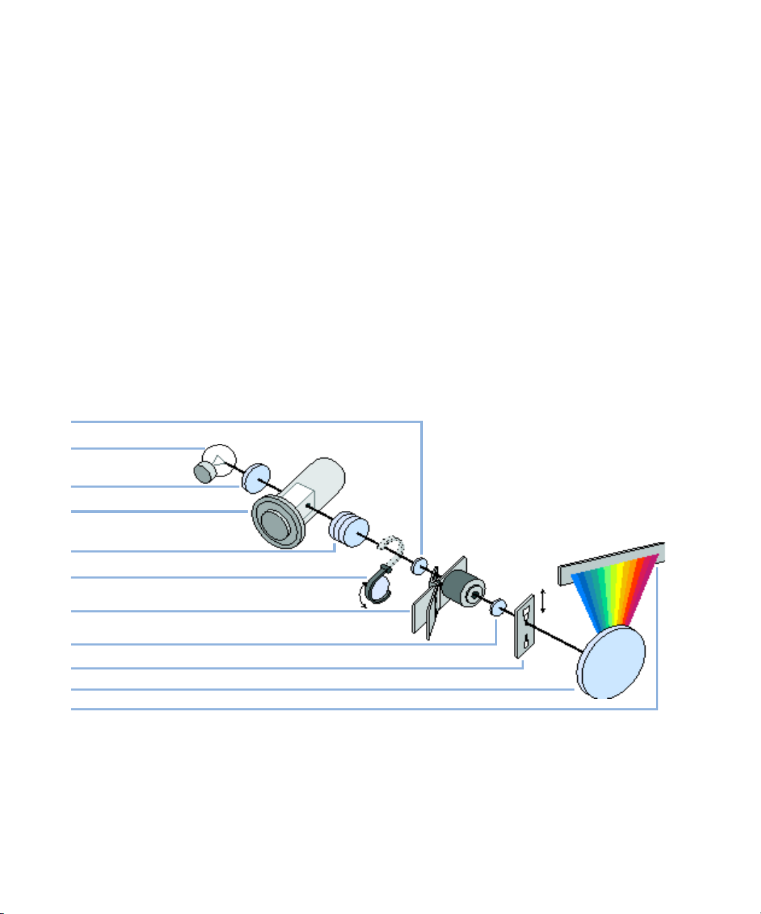
The optical system of the detector is shown in Figure below. Its illumination
source is a combination of a deuterium-arc-discharge lamp for the ultraviolet
(UV) wavelength range and a tungsten lamp for the visible (VIS) and
short-wave near-infrared (SWNIR) wavelength range. The image of the
filament of the tungsten lamp is focused on the discharge aperture of the
deuterium lamp by means of a special rear-access lamp design which allows
both light sources to be optically combined and share a common axis to the
source lens. The achromat (source lens) forms a single, focused beam of light
through the flow cell. Each cell room and lamp are separated by a quartz
window which can be cleaned or replaced. In the spectrograph, light is being
dispersed onto the diode array by a holographic grating. This allows
simultaneous access to all wavelength information.
8Zaahjeedgil^cYdl
Ijc\hiZcaVbe
Introduction
Optical System
1
8djea^c\aZch
9ZjiZg^jbaVbe
6X]gdbVihdjgXZaZch
=dab^jbdm^YZ[^aiZg
;adlXZaa
HeZXigdaZch
Ha^i
<gVi^c\
9^dYZVggVn
Figure 1 Optical System of the Detector
Agilent 1260 Infinity DAD and MWD User Manual 11
Page 12

1 Introduction
Optical System
Lamps The light source for the UV-wavelength range is a deuterium lamp with a
shine-through aperture. As a result of plasma discharge in low-pressure
deuterium gas, the lamp emits light over the 190 nm to approximately 800 nm
wavelength range. The light source for the visible and SWNIR wavelength
range is a low noise tungsten lamp. This lamp emits light over the wavelength
range 470 – 950 nm.
Achromat
(Source Lens)
Holmium Oxide
Filter
Cell Support
Window
Flow Cell
Compartment
Spectrograph The spectrograph material is ceramic to reduce thermal effects to a minimum.
The achromat receives the light from both lamps and focuses it so that the
beam passes through the flow cell.
The holmium oxide filter is electromechanically actuated. During the holmium
filter test it moves into the light path.
The cell support window assembly separates the holmium filter area from the
flow cell area.
The optical unit has a flow cell compartment for easy access to flow cells. A
variety of optional flow cells can be inserted using the same quick, simple
mounting system. The flow cell can be removed to check the optical and
electronic performance of the detector without having influences from the
flow cell.
The spectrograph consists of the spectrograph lens, the variable entrance slit,
the grating and the photodiode array with front-end electronics. The
spectrograph lens refocuses the light beam after it has passed through the flow
cell. The sampling interval of the diode array is < 1 nm over the wavelength
range 190 – 950 nm. Depending on the wavelength this varies from 1.0 to 1.25
diodes per nanometer (for example a diode every 0.8 to 1 nm).
For a small wavelength range, the small non-linearity could be neglected. With
the wavelength range from 190 – 950 nm a new approach is required to
achieve wavelength accuracy over the full range. Each spectrograph is
calibrated individually. The calibration data is stored in the spectrograph on
an EEPROM. Based on these data, the built-in processors calculate absorbance
data with linear intervals (1.0, 2.0, …) between data points. This results in an
excellent wavelength accuracy and instrument-to-instrument reproducibility.
Variable Entranc e
Slit System
12 Agilent 1260 Infinity DAD and MWD User Manual
The micro-slit system makes use of the mechanical properties of silicon
combined with the precise structuring capabilities of bulk micro-machining. It
combines the required optical functions — slit and shutter — in a simple and
compact component. The slit width is directly controlled by the
micro-processor of the instrument and can be set as method parameter.
Page 13

Introduction
Optical System
Grating The combination of dispersion and spectral imaging is accomplished by using
a concave holographic grating. The grating separates the light beam into all its
component wavelengths and reflects the light onto the photodiode array.
Diode Array The diode array is a series of 1024 individual photodiodes and control circuits
located on a ceramic carrier. With a wavelength range from 190 – 950 nm the
sampling interval is < 1 nm.
1
Agilent 1260 Infinity DAD and MWD User Manual 13
Page 14

1 Introduction
Early Maintenance Feedback (EMF)
Early Maintenance Feedback (EMF)
Maintenance requires the exchange of components which are subject to wear
or stress. Ideally, the frequency at which components are exchanged should be
based on the intensity of usage of the module and the analytical conditions,
and not on a predefined time interval. The early maintenance feedback (EMF)
feature monitors the usage of specific components in the instrument, and
provides feedback when the user-selectable limits have been exceeded. The
visual feedback in the user interface provides an indication that maintenance
procedures should be scheduled.
EMF Counters
EMF counters increment with use and can be assigned a maximum limit which
provides visual feedback in the user interface when the limit is exceeded.
Some counters can be reset to zero after the required maintenance procedure.
Using the EMF Counters
The user-settable EMF limits for the EMF Counters enable the early maintenance
feedback to be adapted to specific user requirements. The useful maintenance
cycle is dependent on the requirements for use. Therefore, the definition of the
maximum limits need to be determined based on the specific operating
conditions of the instrument.
Setting the EMF Limits
The setting of the EMF limits must be optimized over one or two maintenance
cycles. Initially the default EMF limits should be set. When instrument
performance indicates maintenance is necessary, take note of the values
displayed by the EMF counters. Enter these values (or values slightly less than
the displayed values) as EMF limits, and then reset the EMF counters to zero.
The next time the EMF counters exceed the new EMF limits, the EMF flag will be
displayed, providing a reminder that maintenance needs to be scheduled.
14 Agilent 1260 Infinity DAD and MWD User Manual
Page 15

Instrument Layout
The industrial design of the module incorporates several innovative features.
It uses Agilent’s E-PAC concept for the packaging of electronics and
mechanical assemblies. This concept is based upon the use of expanded
polypropylene (EPP) layers of foam plastic spacers in which the mechanical
and electronic boards components of the module are placed. This pack is then
housed in a metal inner cabinet which is enclosed by a plastic external
cabinet. The advantages of this packaging technology are:
• virtual elimination of fixing screws, bolts or ties, reducing the number of
components and increasing the speed of assembly/disassembly,
• the plastic layers have air channels molded into them so that cooling air can
be guided exactly to the required locations,
• the plastic layers help cushion the electronic and mechanical parts from
physical shock, and
• the metal inner cabinet shields the internal electronics from
electromagnetic interference and also helps to reduce or eliminate radio
frequency emissions from the instrument itself.
Introduction
Instrument Layout
1
Agilent 1260 Infinity DAD and MWD User Manual 15
Page 16

1 Introduction
Electrical Connections
Electrical Connections
• The CAN bus is a serial bus with high speed data transfer. The two
connectors for the CAN bus are used for internal module data transfer and
synchronization.
• Two independent analog outputs provide signals for integrators or data
handling.
• The REMOTE connector may be used in combination with other analytical
instruments from Agilent Technologies if you want to use features such as
start, stop, common shut down, prepare, and so on.
• With the appropriate software, the RS-232C connector may be used to
control the module from a computer through a RS-232C connection. This
connector is activated and can be configured with the configuration switch.
• The power input socket accepts a line voltage of 100 – 240 VAC ± 10 % with a
line frequency of 50 or 60 Hz. Maximum power consumption varies by
module. There is no voltage selector on your module because the power
supply has wide-ranging capability. There are no externally accessible
fuses, because automatic electronic fuses are implemented in the power
supply.
NOTE
16 Agilent 1260 Infinity DAD and MWD User Manual
Never use cables other than the ones supplied by Agilent Technologies to ensure proper
functionality and compliance with safety or EMC regulations.
Page 17
Serial Number Information (ALL)
The serial number information on the instrument labels provide the following
information:
CCXZZ00000 Format
CC Country of manufacturing (DE Germany)
X Alphabetic character A-Z (used by manufacturing)
ZZ Alpha-numeric code 0-9, A-Z, where each combination
unambiguously denotes a module (there can be more than one
code for the same module)
00000 Serial number
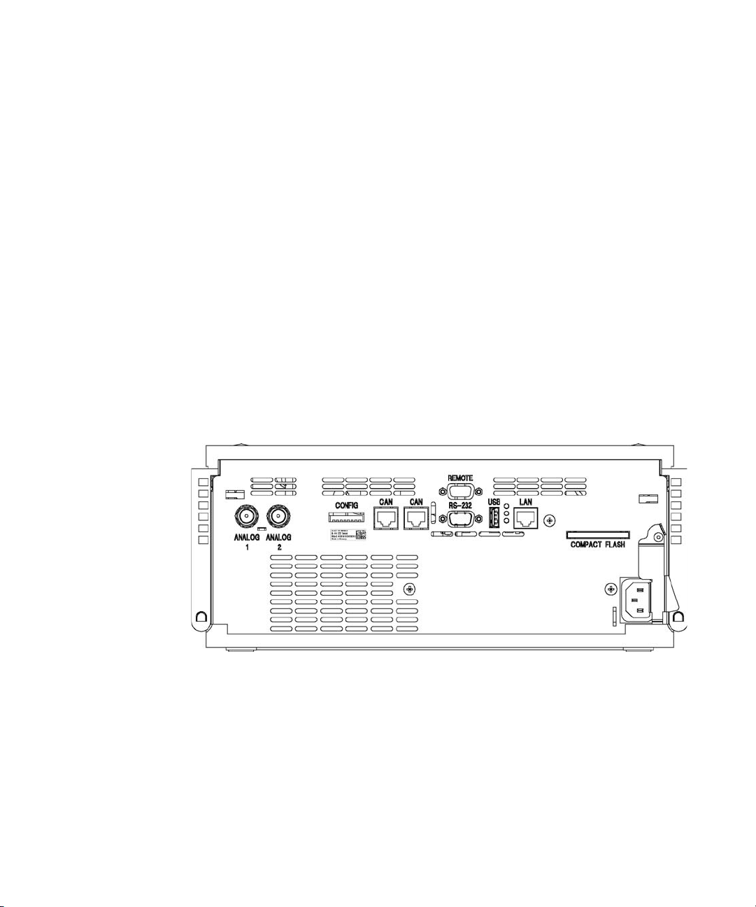
Rear view of the module
Introduction
Electrical Connections
1
Figure 2 Rear View of Detector
Agilent 1260 Infinity DAD and MWD User Manual 17
Page 18

1 Introduction
Interfaces
Interfaces
The Agilent 1200 Infinity Series modules provide the following interfaces:
Ta bl e 1 Agilent 1200 Infinity Series Interfaces
Module CAN LAN/BCD
(optional)
Pumps
G1310B Iso Pump
G1311B Quat Pump
G1311C Quat Pump VL
G1312B Bin Pump
G1312C Bin Pump VL
1376A Cap Pump
G2226A Nano Pump
G4220A/B Bin Pump 2 No Yes Yes No Yes
G1361A Prep Pump 2 Yes No Yes No Yes CAN-DC- OUT for CAN
Samplers
G1329B ALS
G2260A Prep ALS
G1364B FC-PS
G1364C FC-AS
G1364D FCG1367E HiP ALS
G1377A HiP micro ALS
G2258A DL ALS
μS
2 Ye s N o Ye s 1 Ye s
2 Yes No Yes No Yes THERMOSTAT for
2 Yes No Yes No Yes THERMOSTAT for
LAN
(on-board)
RS-232 Analog APG
Remote
Special
slaves
G1330B
G1330B
CAN-DC- OUT for CAN
slaves
G4226A ALS 2 Yes No Yes No Yes
Detectors
G1314B VWD VL
G1314C VWD VL+
G1314E/F VWD 2 No Yes Yes 1 Yes
2 Ye s N o Ye s 1 Ye s
18 Agilent 1260 Infinity DAD and MWD User Manual
Page 19

Ta bl e 1 Agilent 1200 Infinity Series Interfaces
Introduction
Interfaces
1
Module CAN LAN/BCD
(optional)
G4212A/B DAD 2 No Yes Yes 1 Yes
G1315C DAD VL+
G1365C MWD
G1315D DAD VL
G1365D MWD VL
G1321B FLD
G1362A RID
G4280A ELSD No No No Yes Yes Yes EXT Contact
Others
G1316A/C TCC 2 No No Yes No Yes
G1322A DEG No No No No No Yes AUX
G1379B DEG No No No Yes No No AUX
G4227A Flex Cube 2 No No No No No
G4240A CHIP CUBE 2 Yes No Yes No Yes CAN-DC- OUT for CAN
2 N o Ye s Ye s 2 Ye s
2 Ye s N o Ye s 1 Ye s
LAN
(on-board)
RS-232 Analog APG
Remote
Special
AUTOZERO
slaves
THERMOSTAT for
G1330A/B (NOT USED)
NOTE
The detector (DAD/MWD/FLD/VWD/RID) is the preferred access point for control via
LAN. The inter-module communication is done via CAN.
• CAN connectors as interface to other modules
• LAN connector as interface to the control software
• RS-232C as interface to a computer
• REMOTE connector as interface to other Agilent products
• Analog output connector(s) for signal output
Agilent 1260 Infinity DAD and MWD User Manual 19
Page 20

1 Introduction
Interfaces
Interfaces Overview
CAN
The CAN is inter-module communication interface. It is a 2-wire serial bus
system supporting high speed data communication and real-time requirement.
LAN
The modules have either an interface slot for an LAN card (e.g. Agilent
G1369A/B LAN Interface) or they have an on-board LAN interface (e.g.
detectors G1315C/D DAD and G1365C/D MWD). This interface allows the
control of the module/system via a connected PC with the appropriate control
software.
NOTE
NOTE
If an Agilent detector (DAD/MWD/FLD/VWD/RID) is in the system, the LAN should be
connected to the DAD/MWD/FLD/VWD/RID (due to higher data load). If no Agilent
detector is part of the system, the LAN interface should be installed in the pump or
autosampler.
RS-232C (Serial)
The RS-232C connector is used to control the module from a computer
through RS-232C connection, using the appropriate software. This connector
can be configured with the configuration switch module at the rear of the
module. Refer to Communication Settings for RS-232C.
There is no configuration possible on main boards with on-board LAN. These are
pre-configured for
• 19200 baud,
• 8 data bit with no parity and
• one start bit and one stop bit are always used (not selectable).
The RS-232C is designed as DCE (data communication equipment) with a
9-pin male SUB-D type connector. The pins are defined as:
20 Agilent 1260 Infinity DAD and MWD User Manual
Page 21
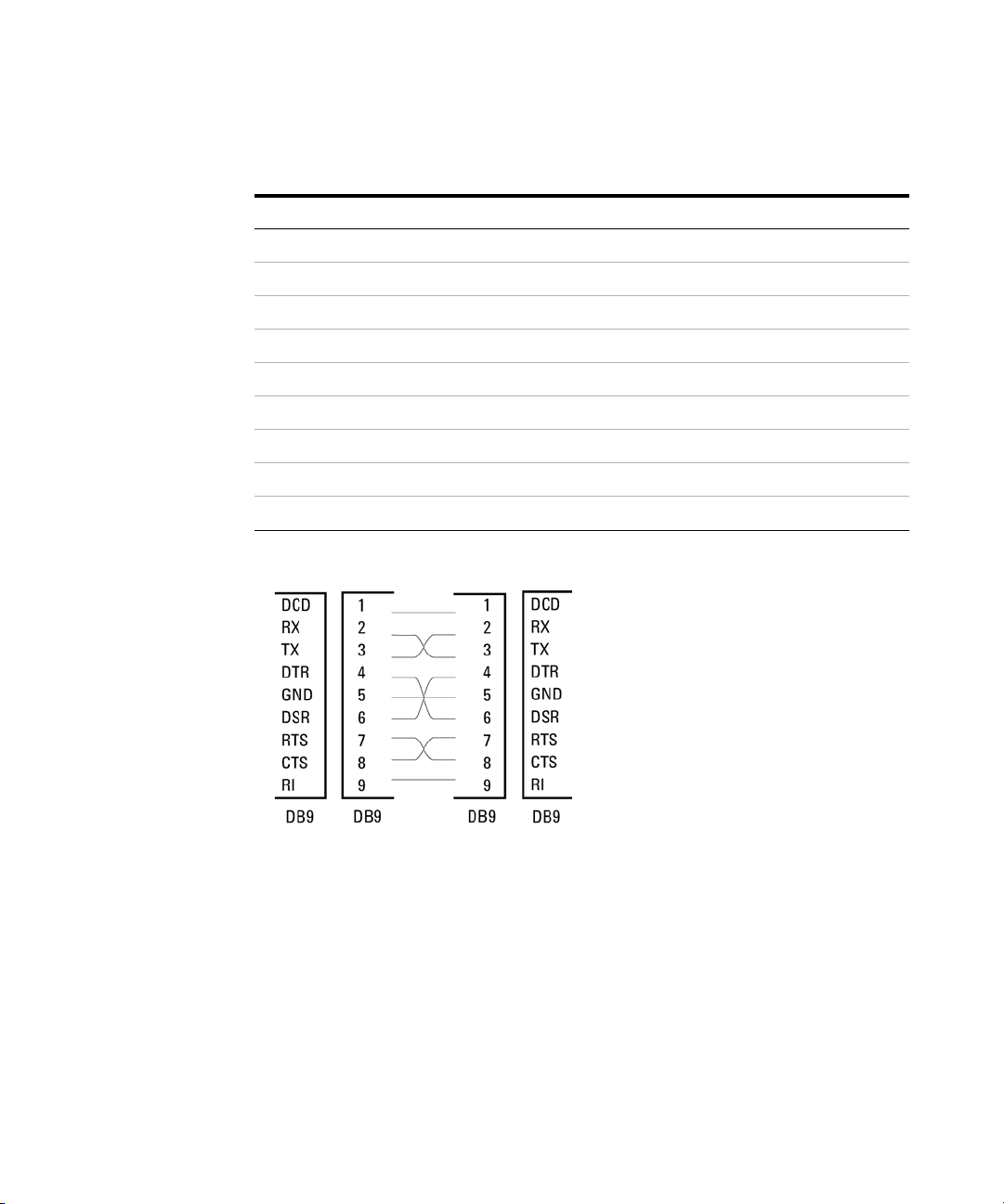
Ta bl e 2 RS-232C Connection Table
Pin Direction Function
1In DCD
2In RxD
3Out TxD
4 Out DTR
5Ground
6In DSR
7Out RTS
8In CTS
9In RI
Introduction
Interfaces
1
>chigjbZci
BVaZ ;ZbVaZ ;ZbVaZ BVaZ
E8
Figure 3 RS-232 Cable
Analog Signal Output
The analog signal output can be distributed to a recording device. For details
refer to the description of the module’s main board.
Agilent 1260 Infinity DAD and MWD User Manual 21
Page 22

1 Introduction
Interfaces
APG Remote
The APG Remote connector may be used in combination with other analytical
instruments from Agilent Technologies if you want to use features as common
shut down, prepare, and so on.
Remote control allows easy connection between single instruments or systems
to ensure coordinated analysis with simple coupling requirements.
The subminiature D connector is used. The module provides one remote
connector which is inputs/outputs (wired- or technique).
To provide maximum safety within a distributed analysis system, one line is
dedicated to SHUT DOWN the system’s critical parts in case any module detects
a serious problem. To detect whether all participating modules are switched
on or properly powered, one line is defined to summarize the POWER ON state
of a ll connec t e d m odules. C o ntrol o f a nalysi s i s maintained by signa l r eadiness
READY for next analysis, followed by START of run and optional STOP of run
triggered on the respective lines. In addition PREPARE and START REQUEST may
be issued. The signal levels are defined as:
• standard TTL levels (0 V is logic true, + 5.0 V is false),
• fan-out is 10,
• input load is 2.2 kOhm against + 5.0 V, and
• output are open collector type, inputs/outputs (wired- or technique).
NOTE
22 Agilent 1260 Infinity DAD and MWD User Manual
All common TTL circuits operate with a 5 V power supply. A TTL signal is defined as "low"
or L when between 0 V and 0.8 V and "high" or H when between 2.0 V and 5.0 V (with
respect to the ground terminal).
Page 23

Introduction
Interfaces
Ta bl e 3 Remote Signal Distribution
Pin Signal Description
1 DGND Digital ground
2 PREPARE (L) Request to prepare for analysis (for example, calibration, detector
lamp on). Receiver is any module performing pre-analysis activities.
3 START (L) Request to start run / timetable. Receiver is any module
performing run-time controlled activities.
4 SHUT DOWN (L) System has serious problem (for example, leak: stops pump).
Receiver is any module capable to reduce safety risk.
5 Not used
6 POWER ON (H) All modules connected to system are switched on. Receiver is any
module relying on operation of others.
7 READY (H) System is ready for next analysis. Receiver is any sequence
controller.
8 STOP (L) Request to reach system ready state as soon as possible (for
example, stop run, abort or finish and stop injection). Receiver is any
module performing run-time controlled activities.
1
9 START REQUEST (L) Request to start injection cycle (for example, by start key on any
module). Receiver is the autosampler.
Special Interfaces
Some modules have module specific interfaces/connectors. They are described
in the module documentation.
Agilent 1260 Infinity DAD and MWD User Manual 23
Page 24
1 Introduction
Setting the 8-bit Configuration Switch
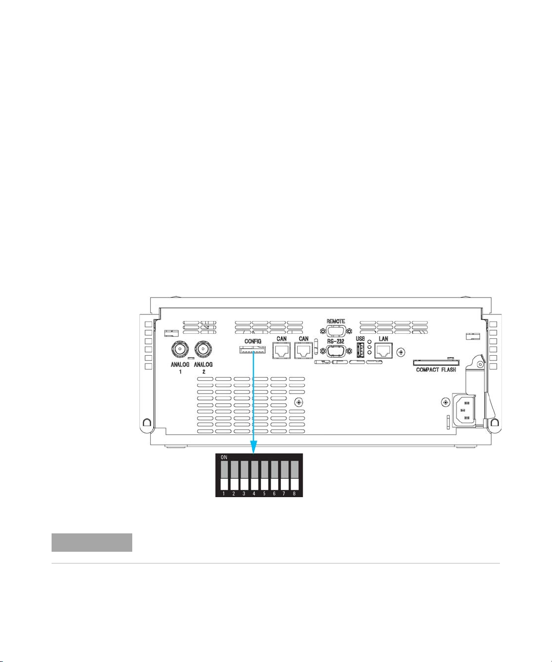
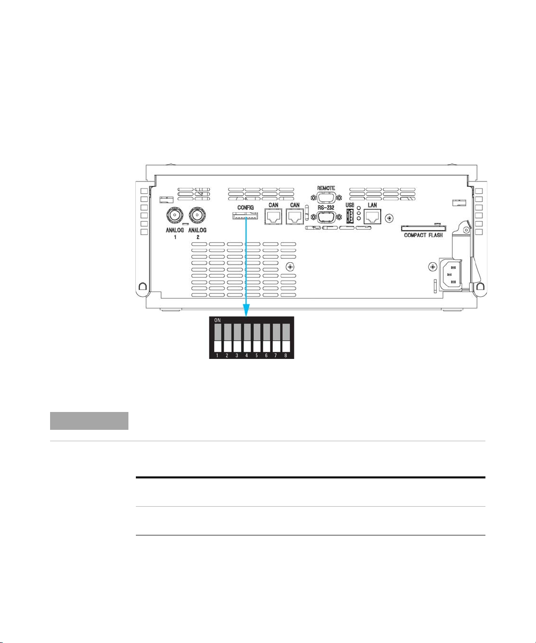
Setting the 8-bit Configuration Switch
Setting the 8-bit Configuration Switch (with On-Board LAN)
The 8-bit configuration switch is located at the rear of the module. Switch
settings provide configuration parameters for LAN, serial communication
protocol and instrument specific initialization procedures.
All modules with on-board LAN, e.g. G1315/65C/D, G1314D/E, G4212A,
G4220A:
• Default is ALL switches DOWN (best settings) - Bootp mode for LAN.
• For specific LAN modes switches 3-8 must be set as required.
• For boot/test modes switches 1+2 must be UP plus required mode.
Figure 4 Location of Configuration Switch
NOTE
24 Agilent 1260 Infinity DAD and MWD User Manual
To perform any LAN configuration, SW1 and SW2 must be set to OFF. For details on the
LAN settings/configuration refer to chapter “LAN Configuration”.
Page 25

Setting the 8-bit Configuration Switch
Ta bl e 4 8-bit Configuration Switch (with on-board LAN)
Mode Function
SW 1 SW 2 SW 3 SW 4 SW 5 SW 6 SW 7 SW 8
LAN 00 Link Configuration Init Mode Selection
Auto-negotiation 0 xxxxx
10 MBit, half-duplex 1 00xxx
10 MBit, full-duplex 1 0 1xxx
100 MBit, half-duplex 1 1 0 xxx
100 MBit, full-duplex 1 1 1 x x x
Bootp x x x 000
Bootp & Store x x x 001
Using Stored x x x 0 1 0
Using Default x x x 0 11
TEST 1 1 System NVRAM
Introduction
1
Boot Resident System 1 x
Revert to Default Data (Coldstart) x x x 1
Legend:
0 (switch down), 1 (switch up), x (any position)
NOTE
Agilent 1260 Infinity DAD and MWD User Manual 25
When selecting the mode TEST, the LAN settings are: Auto-Negotiation & Using Stored.
Page 26

1 Introduction
Setting the 8-bit Configuration Switch
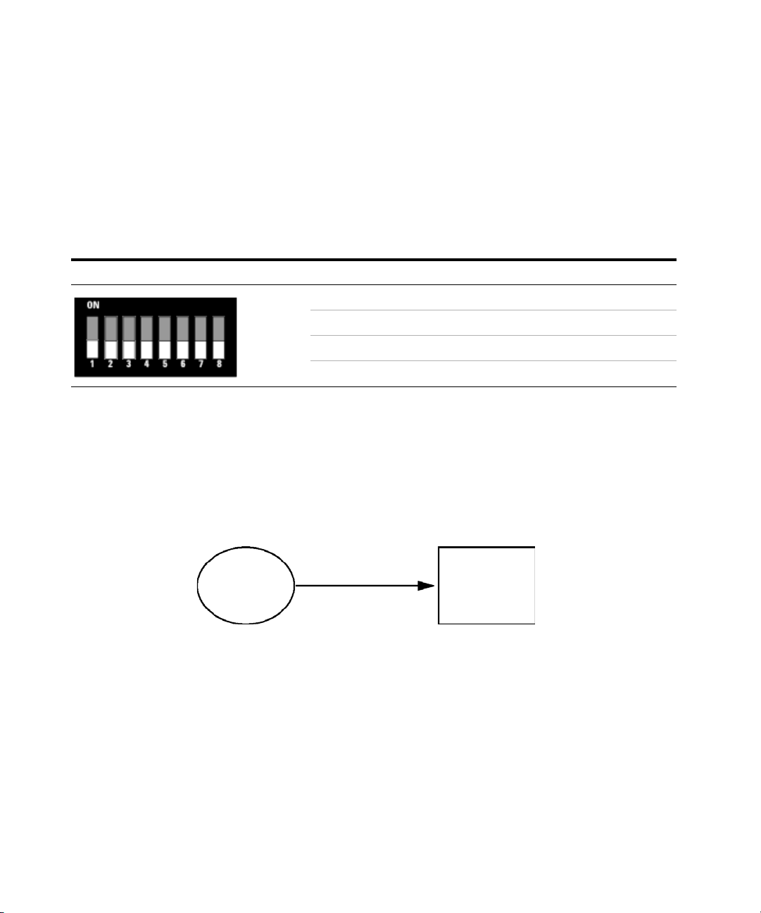
Setting the 8-bit Configuration Switch (without On-Board LAN)
The 8-bit configuration switch is located at the rear of the module.
Modules that do not have their own LAN interface (e.g. the TCC) can be
controlled through the LAN interface of another module and a CAN
connection to that module.
Figure 5 Configuration switch (settings depend on configured mode)
All modules without on-board LAN:
• default is ALL DIPS DOWN (best settings) - Bootp mode for LAN
• for boot/test modes DIPS 1+2 must be UP plus required mode
Switch settings provide configuration parameters for GPIB address, serial
communication protocol and instrument specific initialization procedures.
NOTE
NOTE
26 Agilent 1260 Infinity DAD and MWD User Manual
With the introduction of the Agilent 1260 Infinity, all GPIB interfaces have been removed.
The preferred communication is LAN.
The following tables represent the configuration switch settings for the modules without
on-board LAN only.
Page 27

Introduction
Setting the 8-bit Configuration Switch
Ta bl e 5 8-bit Configuration Switch (without on-board LAN)
Mode Select12345678
1
NOTE
RS-232C 0 1 Baudrate Data
Bits
Reserved 1 0 Reserved
TEST/BOOT 1 1 RSVD SYS RSVD RSVD FC
Parity
The LAN settings are done on the LAN Interface Card G1369A/B. Refer to the
documentation provided with the card.
Agilent 1260 Infinity DAD and MWD User Manual 27
Page 28

1 Introduction
Setting the 8-bit Configuration Switch
Communication Settings for RS-232C
The communication protocol used in the column compartment supports only
hardware handshake (CTS/RTR).
Switches 1 in down and 2 in up position define that the RS-232C parameters
will be changed. Once the change has been completed, the column instrument
must be powered up again in order to store the values in the non-volatile
memory.
Ta bl e 6 Communication Settings for RS-232C Communication (without on-board LAN)
Mode
Select
RS-232C 0 1 Baudrate Data Bits Parity
12345 6 78
Use the following tables for selecting the setting which you want to use for
RS-232C communication. The number 0 means that the switch is down and 1
means that the switch is up.
Ta bl e 7 Baudrate Settings (without on-board LAN)
Switches Baud Rate Switches Baud Rate
345 345
0 0 0 9600 1 0 0 9600
0 0 1 1200 1 0 1 14400
0 1 0 2400 1 1 0 19200
0 1 1 4800 1 1 1 38400
Ta bl e 8 Data Bit Settings (without on-board LAN)
Switch 6 Data Word Size
0 7 Bit Communication
1 8 Bit Communication
28 Agilent 1260 Infinity DAD and MWD User Manual
Page 29

Introduction
Setting the 8-bit Configuration Switch
Ta bl e 9 Parity Settings (without on-board LAN)
Switches Parity
78
0 0 No Parity
1 0 Odd Parity
11 Even Parity
One start bit and one stop bit are always used (not selectable).
Per default, the module will turn into 19200 baud, 8 data bit with no parity.
1
Agilent 1260 Infinity DAD and MWD User Manual 29
Page 30

1 Introduction
Setting the 8-bit Configuration Switch
Special Settings
The special settings are required for specific actions (normally in a service
case).
NOTE
The tables include both settings for modules – with on-board LAN and without on-board
LAN. They are identified as LAN and no LAN.
Boot-Resident
Firmware update procedures may require this mode in case of firmware
loading errors (main firmware part).
If you use the following switch settings and power the instrument up again,
the instrument firmware stays in the resident mode. It is not operable as a
module. It only uses basic functions of the operating system for example, for
communication. In this mode the main firmware can be loaded (using update
utilities).
Ta bl e 1 0 Boot Resident Settings (without on-board LAN)
Mode Select SW1 SW2 SW3 SW4 SW5 SW6 SW7 SW8
LAN TEST/BOOT11100000
No LAN TEST/BOOT11001000
30 Agilent 1260 Infinity DAD and MWD User Manual
Page 31

Introduction
Setting the 8-bit Configuration Switch
Forced Cold Start
A forced cold start can be used to bring the module into a defined mode with
default parameter settings.
1
CAUTION
Loss of data
Forced cold start erases all methods and data stored in the non-volatile memory.
Exceptions are diagnosis and repair log books which will not be erased.
➔ Save your methods and data before executing a forced cold start.
If you use the following switch settings and power the instrument up again, a
forced cold start has been completed.
Ta bl e 1 1 Forced Cold Start Settings (without on-board LAN)
Mode Select SW1 SW2 SW3 SW4 SW5 SW6 SW7 SW8
LAN TEST/BOOT11000001
No LAN TEST/BOOT11001001
Agilent 1260 Infinity DAD and MWD User Manual 31
Page 32

1 Introduction
Setting the 8-bit Configuration Switch
32 Agilent 1260 Infinity DAD and MWD User Manual
Page 33

Agilent 1260 Infinity DAD and MWD User Manual
2
Site Requirements and Specifications
Site Requirements 34
Physical Specifications 37
Performance Specifications 38
Specifications 38
Specification Conditions 41
This chapter provides information on environmental requirements, physical and
performance specifications.
Agilent Technologies
33
Page 34

2 Site Requirements and Specifications
Site Requirements
Site Requirements
A suitable environment is important to ensure optimal performance of the
instrument.
Power Considerations
The module power supply has wide ranging capability. It accepts any line
voltage in the range described in Table 12 on page 37. Consequently there is
no voltage selector in the rear of the module. There are also no externally
accessible fuses, because automatic electronic fuses are implemented in the
power supply.
WARNING
WARNING
CAUTION
Hazard of electrical shock or damage of your instrumentation
can result, if the devices are connected to a line voltage higher than specified.
➔ Connect your instrument to the specified line voltage only.
Module is partially energized when switched off, as long as the power cord is
plugged in.
Repair work at the module can lead to personal injuries, e.g. electrical shock, when
the cover is opened and the module is connected to power.
➔ Always unplug the power cable before opening the cover.
➔ Do not connect the power cable to the instrument while the covers are removed.
Unaccessable power plug.
In case of emergency it must be possible to disconnect the instrument from the power
line at any time.
➔ Make sure the power connector of the instrument can be easily reached and
unplugged.
➔ Provide sufficient space behind the power socket of the instrument to unplug the
cable.
34 Agilent 1260 Infinity DAD and MWD User Manual
Page 35

Power Cords
Different power cords are offered as options with the module. The female end
of all power cords is identical. It plugs into the power-input socket at the rear.
The male end of each power cord is different and designed to match the wall
socket of a particular country or region.
Site Requirements and Specifications
Site Requirements
2
WARNING
WARNING
WARNING
Absence of ground connection or use of unspecified power cord
The absence of ground connection or the use of unspecified power cord can lead to
electric shock or short circuit.
➔ Never operate your instrumentation from a power outlet that has no ground
connection.
➔ Never use a power cord other than the Agilent Technologies power cord designed
for your region.
Use of unsupplied cables
Using cables not supplied by Agilent Technologies can lead to damage of the
electronic components or personal injury.
➔ Never use cables other than the ones supplied by Agilent Technologies to ensure
proper functionality and compliance with safety or EMC regulations.
Unintended use of supplied power cords
Using power cords for unintended purposes can lead to personal injury or damage of
electronic equipment.
➔ Never use the power cords that Agilent Technologies supplies with this instrument
for any other equipment.
Agilent 1260 Infinity DAD and MWD User Manual 35
Page 36

2 Site Requirements and Specifications
Site Requirements
Bench Space
The module dimensions and weight (see Table 12 on page 37) allow you to
place the module on almost any desk or laboratory bench. It needs an
additional 2.5 cm (1.0 inches) of space on either side and approximately 8 cm
(3.1 inches) in the rear for air circulation and electric connections.
If the bench should carry an Agilent system, make sure that the bench is
designed to bear the weight of all modules.
The module should be operated in a horizontal position.
Environment
Your detector will work within the specifications at ambient temperatures and
relative humidity described in Table 12 on page 37.
ASTM drift tests require a temperature change below 2 °C/hour (3.6 °F/hour)
over one hour period. Our published drift specification (refer also to
“Specifications” on page 38) is based on these conditions. Larger ambient
temperature changes will result in larger drift.
Better drift performance depends on better control of the temperature
fluctuations. To realize the highest performance, minimize the frequency and
the amplitude of the temperature changes to below 1 °C/hour (1.8 °F/hour).
Turbulences around one minute or less can be ignored.
NOTE
CAUTION
36 Agilent 1260 Infinity DAD and MWD User Manual
The module is designed to operate in a typical electromagnetic environment (EN61326-1)
where RF transmitters, such as mobile phones, should not be used in close proximity.
Condensation within the module
Condensation will damage the system electronics.
➔ Do not store, ship or use your module under conditions where temperature
fluctuations could cause condensation within the module.
➔ If your module was shipped in cold weather, leave it in its box and allow it to warm
slowly to room temperature to avoid condensation.
Page 37

Physical Specifications
Ta bl e 1 2 Physical Specifications
Type Specification Comments
Weight 11.5 kg (26 lbs)
Site Requirements and Specifications
Physical Specifications
2
Dimensions (height ×
width × depth)
Line voltage 100 – 240 VAC, ± 10% Wide-ranging capability
Line frequency 50 or 60 Hz, ± 5%
Power consumption 160 VA / 160 W / 546 BTU Maximum
Ambient operating
temperature
Ambient non-operating
temperature
Humidity < 95%, at 25–40 °C (77–104 °F) Non-condensing
Operating Altitude Up to 2000 m (6562 ft)
Non-operating altitude Up to 4600 m (15091 ft) For storing the module
Safety standards: IEC, CSA, ULInstallation Category II, Pollution Degree 2 For indoor use only.
140 x 345 x 435 mm (5.5 x 13.5 x 17 inches)
0–55 °C (32–131 °F)
-40–70 °C (-4–158 °F)
Agilent 1260 Infinity DAD and MWD User Manual 37
Page 38

2 Site Requirements and Specifications
Performance Specifications
Performance Specifications
Specifications
Ta bl e 1 3 Performance Specifications G1315C/D and G1365C/D
Type Specification Comments
Detection type 1024-element photodiode array
Light source Deuterium and tungsten lamps The UV-lamp is equipped with RFID tag that
holds lamp typical information.
Data rate up to 80 Hz (G1315C/G1365C)
up to 20 Hz (G1315D/G1365D)
Wavelength range 190 – 950 nm
Short term noise
(ASTM) Single and
Multi-Wavelength
Drift
< ± 0.7·10
< 0.9·10
-5
AU at 254 and 750 nm
-3
AU/h at 254 nm
see "Specification Conditions" below
see "Specification Conditions" below
Linear absorbance
range
Wavelength accuracy ± 1 nm Self-calibration with deuterium lines, verification
Wavelength bunching 1 – 400 nm Programmable in steps of 1 nm
Slit width 1, 2, 4 , 8, 16 nm Programmable slit
Diode width < 1 nm
> 2 AU (5 %) at 265 nm see "Specification Conditions" below
with holmium oxide filter
38 Agilent 1260 Infinity DAD and MWD User Manual
Page 39

Site Requirements and Specifications
Ta bl e 1 3 Performance Specifications G1315C/D and G1365C/D
Type Specification Comments
2
Performance Specifications
Flow cells Standard: 13 µL volume, 10 mm cell path length
and 120 bar (1740 psi) pressure maximum
Semi-micro: 5 µL volume, 6 mm cell path length
and 120 bar (1740 psi) pressure maximum
Micro: 2 µL volume, 3 mm cell path length,
120 bar (1740 psi) pressure maximum
Semin-nano: 500 nL volume, 10 mm cell path
length and 50 bar (725 psi) pressure maximum
Nano: 80 nL volume, 10 mm cell path length and
50 bar (725 psi) pressure maximum
High pressure: 1.7 µL volume, 6 mm cell path
length and 400 bar (5800 psi) pressure
maximum
Prep SST: 3 mm cell path length and 120 bar
(1740 psi) pressure maximum
Prep Quartz:0.3 mm cell path length and 20 bar
(290 psi) pressure maximum
Prep Quartz: 0.06 mm cell path length and 20 bar
(290 psi) pressure maximum
Time programmable Wavelength, polarity, peak width, lamp
bandwidth, autobalance, wavelength range,
threshold, spectra storage mode
Spectral tools Data analysis software for spectra evaluation,
including spectral libraries and peak purity
functions
See “Optimization Overview” on page 117
All flow cells are equipped with RFID tags that
hold cell typical information.
Control and data
evaluation
Local Control Agilent Instant Pilot (G4208A) For 1260 systems:
Analog outputs Recorder/integrator: 100 mV or 1 V, output
Agilent ChemStation for LC (32-bit) For 1260 systems:
• Revision B.04.02 DSP2 or above
For 1100/1200 systems:
• Revision B.01.03 or above (G1315C/G1365C)
• Revision B.01.03 SR-2 / B.02.01 SR-2 or
above (G1315D/G1365D)
• B.02.11 or above
For other systems:
• B.02.09 or above
range 0.001 – 2 AU, two outputs
Agilent 1260 Infinity DAD and MWD User Manual 39
Page 40

2 Site Requirements and Specifications
Performance Specifications
Ta bl e 1 3 Performance Specifications G1315C/D and G1365C/D
Type Specification Comments
Communications Controller-area network (CAN), RS-232C, APG
Remote: ready, start, stop and shut-down
signals, LAN
Safety and
maintenance
GLP features RFID for electronics records of flow cell and UV
Housing All materials recyclable.
Others Electronic temperature control (ETC) for the
Extensive diagnostics, error detection and
display (through control module and
ChemStation), leak detection, safe leak
handling, leak output signal for shutdown of
pumping system. Low voltages in major
maintenance areas.
lamp conditions (path length, volume, product
number, serial number, test passed, usage)
Early maintenance feedback (EMF) for
continuous tracking of instrument usage in
terms of lamp burn time with user-setable limits
and feedback messages. Electronic records of
maintenance and errors. Verification of
wavelength accuracy with built-in holmium
oxide filter.
complete optical unit
40 Agilent 1260 Infinity DAD and MWD User Manual
Page 41

Specification Conditions
ASTM: “Standard Practice for Variable Wavelength Photometric Detectors
Used in Liquid Chromatography”.
Reference conditions: cell path length 10 mm, wavelength 254 and 750 nm
with reference wavelength 360 nm/100 nm, slit width 4 nm, time constant 2 s
(equal to response time 4 s), flow 1 mL/min LC-grade Methanol.
Linearity: Linearity is measured with caffeine at 265 nm/4 nm with slit width
4nm and TC 2s (or with RT 4s) with 10mm pathlength.
For environmental conditions refer to “Environment” on page 36
Site Requirements and Specifications
Performance Specifications
2
NOTE
The specifications are based on the standard RFID tag lamp (2140-0820) and may be not
achieved when other lamp types or aged lamps are used.
ASTM drift tests require a temperature change below 2 °C/hour (3.6 °F/hour)
over one hour period. Our published drift specification is based on these
conditions. Larger ambient temperature changes will result in larger drift.
Better drift performance depends on better control of the temperature
fluctuations. To realize the highest performance, minimize the frequency and
the amplitude of the temperature changes to below 1 °C/hour (1.8 °F/hour).
Turbulences around one minute or less can be ignored.
Performance tests should be done with a completely warmed up optical unit (>
two hours). ASTM measurements require that the detector should be turned
on at least 24 h before start of testing.
Time Constant versus Response Time
According to ASTM E1657-98 „Standard Practice of Testing
Variable-Wavelength Photometric Detectors Used in Liquid Chromatography”
the time constant is converted to response time by multiplying by the factor
2.2.
Agilent 1260 Infinity DAD and MWD User Manual 41
Page 42

2 Site Requirements and Specifications
Performance Specifications
42 Agilent 1260 Infinity DAD and MWD User Manual
Page 43

Agilent 1260 Infinity DAD and MWD User Manual
3
Installing the Module
Unpacking the Detector 44
Damaged Packaging 44
Delivery Checklist 45
Optimizing the Stack Configuration 46
Two Stack Configuration 48
Installing the Detector 50
Flow Connections to the Detector 53
Setting up the LAN access 56
This chapter gives information about the preferred stack setup for your system
and the installation of your module.
Agilent Technologies
43
Page 44

3 Installing the Module
Unpacking the Detector
Unpacking the Detector
Damaged Packaging
If the delivery packaging shows signs of external damage, please call your
Agilent Technologies sales and service office immediately. Inform your service
representative that the instrument may have been damaged during shipment.
CAUTION
"Defective on arrival" problems
If there are signs of damage, please do not attempt to install the module. Inspection by
Agilent is required to evaluate if the instrument is in good condition or damaged.
➔ Notify your Agilent sales and service office about the damage.
➔ An Agilent service representative will inspect the instrument at your site and
initiate appropriate actions.
44 Agilent 1260 Infinity DAD and MWD User Manual
Page 45

Delivery Checklist
Ensure all parts and materials have been delivered with the detector. The
delivery checklist is shown below. Please report missing or damaged parts to
your local Agilent Technologies sales and service office.
Ta bl e 1 4 Detector Checklist
Description Quantity
Detector 1
CompactFlash Card 1 (installed) G1315C/G1365C only
Power cable 1
Cross-over network cable 1
Twisted pair network cable 1
Flow cell As ordered
User Manual on Doumentation CD (part of the shipment - not
module specific)
Installing the Module
Unpacking the Detector
3
Accessory kit (p/n G1315-68755) 1
Agilent 1260 Infinity DAD and MWD User Manual 45
Page 46

3 Installing the Module
Optimizing the Stack Configuration
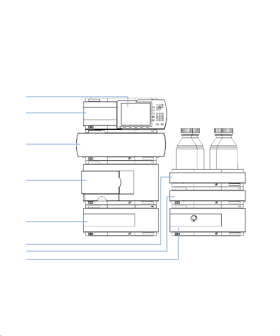
Optimizing the Stack Configuration
If your detector is part of a complete Agilent 1200 Series system, you can
ensure optimum performance by installing the following configuration. This
configuration optimizes the system f low path, ensuring minimum delay
volume.
HdakZciXVW^cZi
KVXjjbYZ\VhhZg
Ejbe
AdXVaJhZg>ciZg[VXZ
6jidhVbeaZg
8dajbcXdbeVgibZci
9ZiZXidg
Figure 6 Recommended Stack Configuration for 1260 (Front View)
46 Agilent 1260 Infinity DAD and MWD User Manual
Page 47

GZbdiZXVWaZ
86C7jhXVWaZid
adXVajhZg^ciZg[VXZ
86C7jhXVWaZ
Installing the Module
Optimizing the Stack Configuration
68edlZg
3
6cVad\YZiZXidg
h^\cVa
&dg'djiejih
eZgYZiZXidg
A6CidA88]ZbHiVi^dc
adXVi^dcYZeZcYhdcYZiZXidg
Figure 7 Recommended Stack Configuration (Rear View)
Agilent 1260 Infinity DAD and MWD User Manual 47
Page 48
3 Installing the Module
Optimizing the Stack Configuration
Two Stack Configuration
To avoid excessive height of the stack when the autosampler thermostat is
added to the system it is recommended to form two stacks. Some users prefer
the lower height of this arrangement even without the autosampler
thermostat. A slightly longer capillary is required between the pump and
autosampler. (See Figure 8 on page 48 and Figure 9 on page 49).
>chiVciE^adi
9ZiZXidg
8dajbcXdbeVgibZci
6jidhVbeaZg
I]ZgbdhiVi[dgi]Z6AH
dei^dcVa
HdakZciXVW^cZi
9Z\VhhZgdei^dcVa
Ejbe
Figure 8 Recommended Two Stack Configuration for 1260 (Front View)
48 Agilent 1260 Infinity DAD and MWD User Manual
Page 49

A6CidXdcigdahd[ilVgZ
86C7jhXVWaZ
id>chiVciE^adi
I]ZgbdXVWaZ
dei^dcVa
GZbdiZXVWaZ
68EdlZg
Installing the Module
Optimizing the Stack Configuration
3
68EdlZg
86C7jhXVWaZ
68EdlZg
Figure 9 Recommended Two Stack Configuration for 1260 (Rear View)
Agilent 1260 Infinity DAD and MWD User Manual 49
Page 50

3 Installing the Module
Installing the Detector
Installing the Detector
Parts required Description
Power cord
LAN cable (cross-over or twisted pair network cable)
All modules in the stack should have the latest firmware installed. If other
revisions are required, check with the Agilent support for best match.
Hardware required Detector (as ordered)
Software required Appropriate control software or G4208A Instant Pilot (optional).
Preparations Locate bench space
Provide power connections
Unpack the module
WARNING
Module is partially energized when switched off, as long as the power cord is
plugged in.
Repair work at the module can lead to personal injuries, e.g. shock hazard, when the
cover is opened and the module is connected to power.
➔ Make sure that it is always possible to access the power plug.
➔ Remove the power cable from the instrument before opening the cover.
➔ Do not connect the power cable to the Instrument while the covers are removed.
NOTE
NOTE
50 Agilent 1260 Infinity DAD and MWD User Manual
Before adding a G1315C/D and G1365C/D into an existing system assure that the existing
modules have been updated to firmware revision A.06.02/B.01.02 or above. Otherwise the
ChemStation “Performance Specifications” on page 38 will not recognize modules.
For G1315C and G1365C assure that the CompactFlash Card is installed in the rear of the
module (required for operation).
Page 51

Installing the Module
Installing the Detector
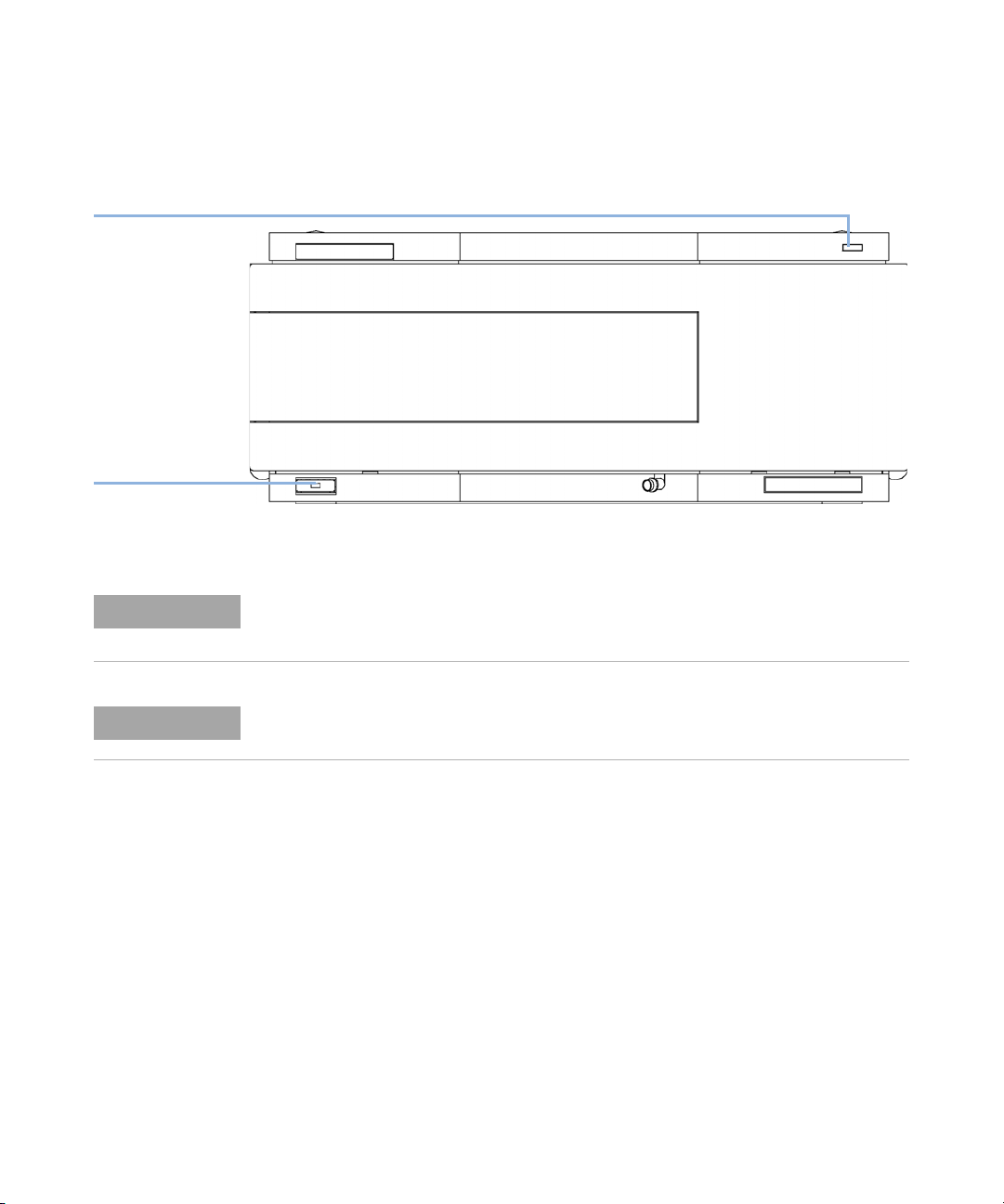
1 Note the MAC address of the LAN interface (rear of the module, under the
configuration switch, see Figure 10 on page 51). It’s required for “LAN
Configuration” on page 57.
2 Place the module in the stack or on the bench in a horizontal position.
3 Ensure the line power switch at the front of the module is OFF.
4 Connect the power cable to the power connector at the rear of the module.
EdlZg
3
Figure 10 Rear View of Detector
5 Connect the CAN cable to other Agilent 1200 Series modules.
6 Connect the LAN cable (e.g. from a Agilent ChemStation as controller) to
the detector's LAN connector.
NOTE
Agilent 1260 Infinity DAD and MWD User Manual 51
In multi-detector configurations the LAN of the G1315C/D and G1365C/D must be used
due to its higher data load.
7 Connect the analog cable(s) (optional).
8 Connect the APG remote cable (optional) for non-Agilent 1200 Series
instruments.
Page 52
3 Installing the Module
Installing the Detector
9 Turn on power by pushing the button at the lower left hand side of the
module. The status LED should be green.
HiVijh^cY^XVidg
\gZZc$nZaadl$gZY
A^cZedlZghl^iX]
l^i]\gZZca^\]i
Figure 11 Front View of Detector
NOTE
NOTE
52 Agilent 1260 Infinity DAD and MWD User Manual
The module is turned on when the line power switch is pressed and the green indicator
lamp is illuminated. The module is turned off when the line power switch is protruding and
the green light is off.
The module was shipped with default configuration settings. To change these settings see
“Configuration Switch” on page 60.
Page 53

Flow Connections to the Detector
Parts required # Description
G1315-68755 Accessory kit
Hardware required Other modules
Preparations Detector is installed in the LC system.
Installing the Module
Flow Connections to the Detector
3
WARNING
NOTE
NOTE
Toxic, flammable and hazardous solvents, samples and reagents
The handling of solvents, samples and reagents can hold health and safety risks.
➔ When working with these substances observe appropriate safety procedures (for
example by wearing goggles, safety gloves and protective clothing) as described in
the material handling and safety data sheet supplied by the vendor and follow good
laboratory practice.
➔ The amount of substances should be reduced to the minimal volume required for
the analysis.
➔ Do not operate the instrument in an explosive atmosphere.
The flow cell is shipped with a filling of isopropanol (also recommended when the
instrument and/or flow cell is shipped to another location). This is to avoid breakage due to
subambient conditions.
The detector should be operated with the front cover in place to protect the flow cell area
against strong drafts from the outside and to cover the deuterium lamp.
Some types of the Agilent deuterium lamps show a light ring during operation. This is not
harmful, refer to “UV-Radiation” on page 272.
Agilent 1260 Infinity DAD and MWD User Manual 53
Page 54

3 Installing the Module
Flow Connections to the Detector
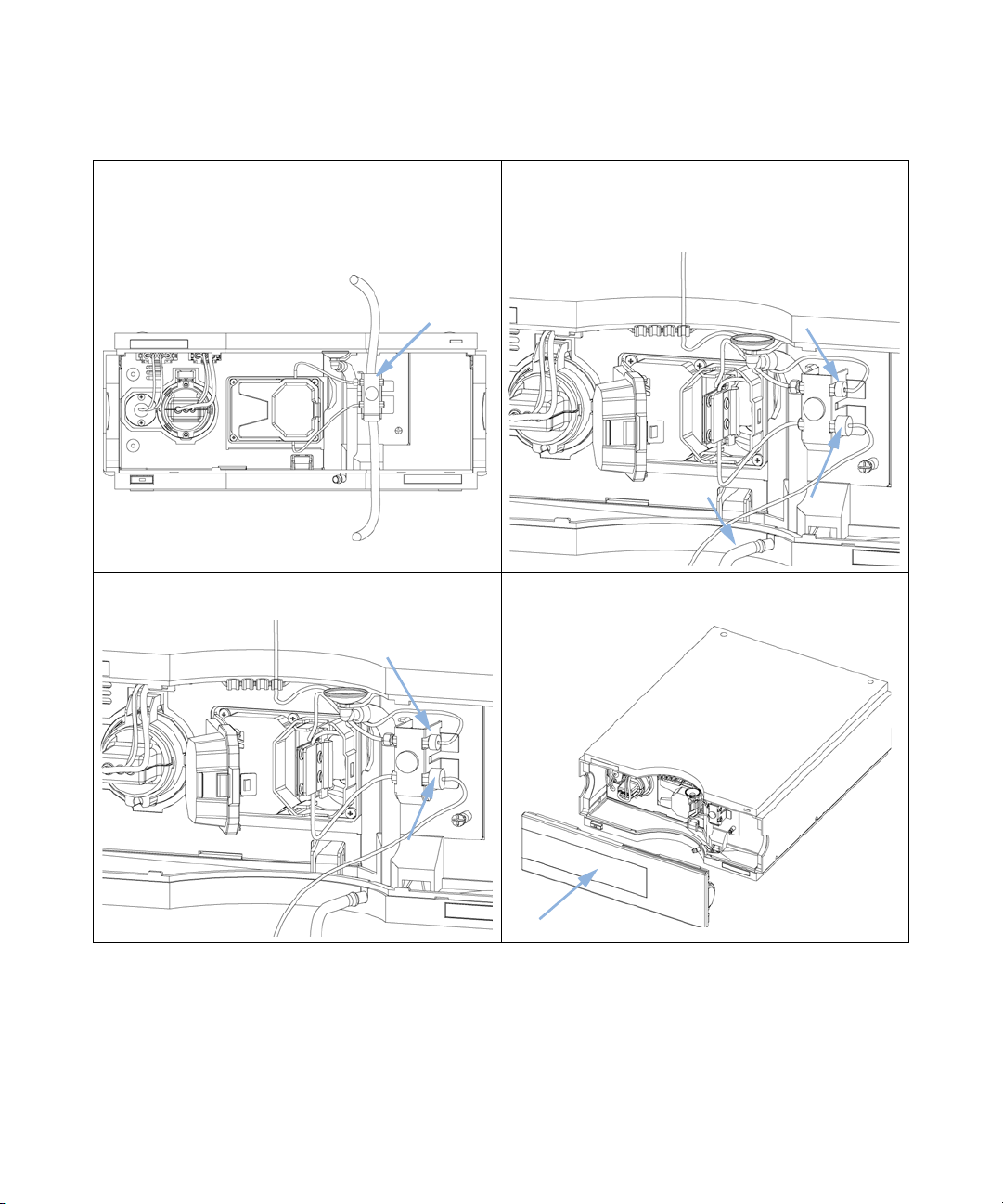
NOTE
Press the release buttons and remove the front cover to
1
gain access to the flow cell area.
3 Insert the flow cell. 4 Connect the flow cell capillaries to the capillary holder
The heat exchanger/capillary and the cell body can be fixed mirror symmetrically to have
both capillaries routed to the bottom or to the top (depending on the routing of the
capillaries to the column). For details see “Replacing Capillaries on a Standard Flow
Cell” on page 209.
2 Press the release button and open the flow cell door.
(top is inlet, bottom is outlet).
54 Agilent 1260 Infinity DAD and MWD User Manual
Page 55
5
If another Agilent module is positioned on top of the
detector, route the tubing assembly waste from the
accessory kit behind the capillary holder and connect the
top end to the other module’s waste outlet.
Iddi]ZgbdYjaZ
IdlVhiZ
Installing the Module
Flow Connections to the Detector
6 Connect the capillary from the column to the capillary
holder (top). Connect the teflon waste tubing to the flow
cell outlet fitting (bottom) and the corrugated waste
tubing to the leak outlet.
3
7 Remove the flow cell and establish a flow and observe for
leaks.
The installation of the detector is complete now.
8 Insert the flow cell, close the cover and replace the front
cover.
Agilent 1260 Infinity DAD and MWD User Manual 55
Page 56

3 Installing the Module
Setting up the LAN access
Setting up the LAN access
Please follow the instructions in “LAN Configuration” on page 57
56 Agilent 1260 Infinity DAD and MWD User Manual
Page 57

Agilent 1260 Infinity DAD and MWD User Manual
4
LAN Configuration
What you have to do first 58
TCP/IP parameter configuration 59
Configuration Switch 60
Initialization mode selection 61
Link configuration selection 65
Automatic Configuration with BootP 66
About Agilent BootP Service 66
How BootP Service Works 67
Situation: Cannot Establish LAN Communication 67
Installation of BootP Service 68
Two Methods to Determine the MAC Address 70
Assigning IP Addresses Using the Agilent BootP Service 71
Changing the IP Address of an Instrument Using the Agilent BootP
Service 74
Storing the settings permanently with Bootp 76
Manual Configuration 77
With Telnet 78
With the Instant Pilot (G4208A) 82
This chapter provides information on connecting the detector to the Agilent
ChemStation PC.
Agilent Technologies
57
Page 58

4 LAN Configuration
What you have to do first
What you have to do first
The module has an on-board LAN communication interface.
1 Note the MAC (Media Access Control) address for further reference. The
MAC or hardware address of the LAN interfaces is a world wide unique
identifier. No other network device will have the same hardware address.
The MAC address can be found on a label at the rear of the module
underneath the configuration switch (see Figure 13 on page 58).
Figure 12 MAC-Label
2 Connect the instrument's LAN interface (see Figure 13 on page 58) to
• the PC network card using a crossover network cable (point-to-point) or
• a hub or switch using a standard LAN cable.
EVgicjbWZgd[i]ZYZiZXidgbV^cWdVgY
GZk^h^dc8dYZ!KZcYdg!NZVgVcYLZZ`d[VhhZbWan
B68VYYgZhh
8djcignd[Dg^\^c
Figure 13 Location of LAN interface and MAC label
58 Agilent 1260 Infinity DAD and MWD User Manual
Page 59

TCP/IP parameter configuration
To operate properly in a network environment, the LAN interface must be
configured with valid TCP/IP network parameters. These parameters are:
• IP address
• Subnet Mask
• Default Gateway
The TCP/IP parameters can be configured by the following methods:
• by automatically requesting the parameters from a network-based BOOTP
Server (using the so-called Bootstrap Protocol)
• by manually setting the parameters using Telnet
• by manually setting the parameters using the Instant Pilot (G4208A)
The LAN interface differentiates between several initialization modes. The
initialization mode (short form ‘init mode’) defines how to determine the
active TCP/IP parameters after power-on. The parameters may be derived
from a Bootp cycle, non-volatile memory or initialized with known default
values. The initialization mode is selected by the configuration switch, see
Table 18 on page 65.
LAN Configuration
TCP/IP parameter configuration
4
Agilent 1260 Infinity DAD and MWD User Manual 59
Page 60
4 LAN Configuration
Configuration Switch
Configuration Switch
The configuration switch can be accessed at the rear of the module.
Figure 14 Location of Configuration Switch
The module is shipped with all switches set to OFF, as shown above.
NOTE
60 Agilent 1260 Infinity DAD and MWD User Manual
To perform any LAN configuration, SW1 and SW2 must be set to OFF.
Ta bl e 1 5 Factory Default Settings
Initialization (‘Init’) Mode Bootp, all switches down. For details see “Initialization mode
selection” on page 61
Link Configuration speed and duplex mode determined by auto-negotiation, for
details see “Link configuration selection” on page 65
Page 61
Initialization mode selection
The following initialization (init) modes are selectable:
Ta bl e 1 6 Initialization Mode Switches
SW 6 SW 7 SW 8 Init Mode
OFF OFF OFF Bootp
OFF OFF ON Bootp & Store
OFF ON OFF Using Stored
OFF ON ON Using Default
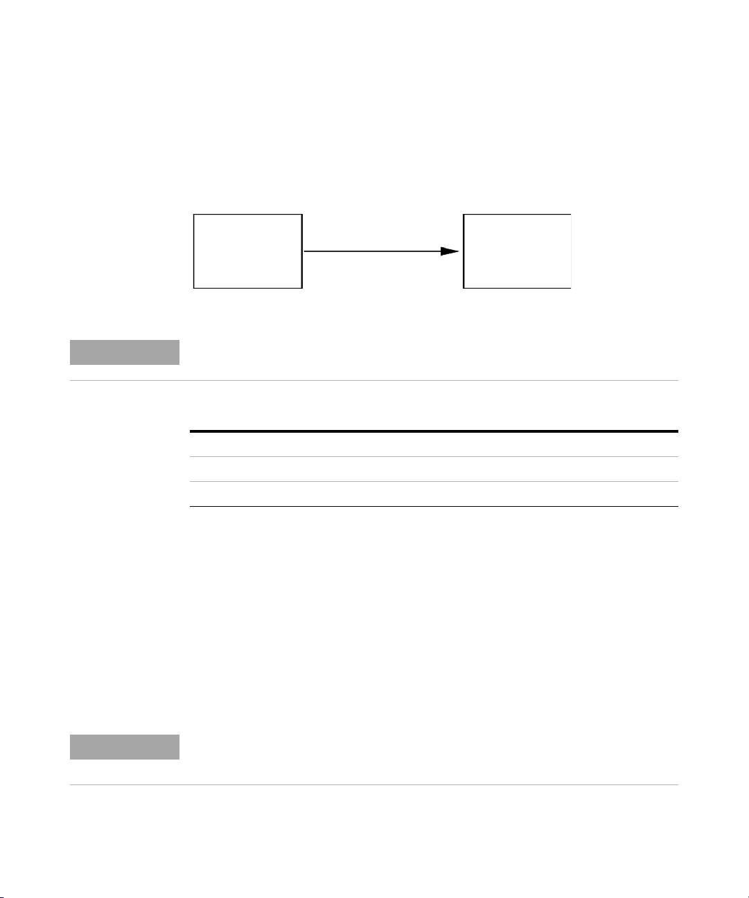
Bootp
When the initialization mode Bootp is selected, the module tries to download
the parameters from a Bootp Server. The parameters obtained become the
active parameters immediately. They are not stored to the non-volatile
memory of the module. Therefore, the parameters are lost with the next power
cycle of the module.
LAN Configuration
Initialization mode selection
4
7ddie
HZgkZg
Figure 15 Bootp (Principle)
Agilent 1260 Infinity DAD and MWD User Manual 61
6Xi^kZ
EVgVbZiZg
Page 62

4 LAN Configuration
Initialization mode selection
Bootp & Store
When Bootp & Store is selected, the parameters obtained from a Bootp Server
become the active parameters immediately. In addition, they are stored to the
non-volatile memory of the module. Thus, after a power cycle they are still
available. This enables a kind of bootp once configuration of the module.
Example: The user may not want to have a Bootp Server be active in his
network all the time. But on the other side, he may not have any other
configuration method than Bootp. In this case he starts the Bootp Server
temporarily, powers on the module using the initialization mode Bootp & Store,
waits for the Bootp cycle to be completed, closes the Bootp Server and powers
off the module. Then he selects the initialization mode Using Stored and
powers on the module again. From now on, he is able to establish the TCP/IP
connection to the module with the parameters obtained in that single Bootp
cycle.
NOTE
7ddie
HZgkZg
Cdc"KdaVi^aZ
G6B
HidgZY
EVgVbZiZg
6Xi^kZ
EVgVbZiZg
Figure 16 Bootp & Store (Principle)
Use the initialization mode Bootp & Store carefully, because writing to the non-volatile
memory takes time. Therefore, when the module shall obtain its parameters from a Bootp
Server every time it is powered on, the recommended initialization mode is Bootp!
62 Agilent 1260 Infinity DAD and MWD User Manual
Page 63

LAN Configuration
Initialization mode selection
Using Stored
When initialization mode Using Stored is selected, the parameters are taken
from the non-volatile memory of the module. The TCP/IP connection will be
established using these parameters. The parameters were configured
previously by one of the described methods.
Cdc"KdaVi^aZ
G6B
6Xi^kZ
HidgZY
EVgVbZiZg
Figure 17 Using Stored (Principle)
EVgVbZiZg
4
Agilent 1260 Infinity DAD and MWD User Manual 63
Page 64
4 LAN Configuration
Initialization mode selection
Using Default
When Using Default is selected, the factory default parameters are taken
instead. These parameters enable a TCP/IP connection to the LAN interface
without further configuration, see Table 17 on page 64.
NOTE
9Z[Vjai
EVgVbZiZg
Figure 18 Using Default (Principle)
Using the default address in your local area network may result in network problems. Take
care and change it to a valid address immediately.
Ta bl e 1 7 Using Default Parameters
IP address: 192.168.254.11
Subnet Mask: 255.255.255.0
Default Gateway not specified
Since the default IP address is a so-called local address, it will not be routed by
any network device. Thus, the PC and the module must reside in the same
subnet.
The user may open a Telnet session using the default IP address and change
the parameters stored in the non-volatile memory of the module. He may then
close the session, select the initialization mode Using Stored, power-on again
and establish the TCP/IP connection using the new parameters.
6Xi^kZ
EVgVbZiZg
When the module is wired to the PC directly (e.g. using a cross-over cable or a
local hub), separated from the local area network, the user may simply keep
the default parameters to establish the TCP/IP connection.
NOTE
64 Agilent 1260 Infinity DAD and MWD User Manual
In the Using Default mode, the parameters stored in the memory of the module are not
cleared automatically. If not changed by the user, they are still available, when switching
back to the mode Using Stored.
Page 65

Link configuration selection
The LAN interface supports 10 or 100 Mbps operation in full- or half-duplex
modes. In most cases, full-duplex is supported when the connecting network
device - such as a network switch or hub - supports IEEE 802.3u
auto-negotiation specifications.
When connecting to network devices that do not support auto-negotiation, the
LAN interface will configure itself for 10- or 100-Mbps half-duplex operation.
For example, when connected to a non-negotiating 10-Mbps hub, the LAN
interface will be automatically set to operate at 10-Mbps half-duplex.
If the module is not able to connect to the network through auto-negotiation,
you can manually set the link operating mode using link configuration
switches on the module.
Ta bl e 1 8 Link Configuration Switches
SW 3 SW 4 SW 5 Link Configuration
LAN Configuration
Link configuration selection
4
OFF - - speed and duplex mode determined by
auto-negotiation
ON OFF OFF manually set to 10 Mbps, half-duplex
ON OFF ON manually set to 10 Mbps, full-duplex
ON ON OFF manually set to 100 Mbps, half-duplex
ON ON ON manually set to 100 Mbps, full-duplex
Agilent 1260 Infinity DAD and MWD User Manual 65
Page 66

4 LAN Configuration
Automatic Configuration with BootP
Automatic Configuration with BootP
NOTE
NOTE
NOTE
NOTE
All examples shown in this chapter will not work in your environment. You need your own
IP-, Subnet-Mask- and Gateway addresses.
Assure that the detector configuration switch is set properly. The setting should be either
BootP or BootP & Store, see Ta b l e 1 6 on page 61.
Assure that the detector connected to the network is powered off.
If the Agilent BootP Service program is not already installed on your PC, then install it from
your Agilent ChemStation DVD, located in folder BootP.
About Agilent BootP Service
The Agilent BootP Service is used to assign the LAN Interface with an IP
address.
The Agilent BootP Service is provided on the ChemStation DVD. The Agilent
BootP Service is installed on a server or PC on the LAN to provide central
administration of IP addresses for Agilent instruments on a LAN. The BootP
service must be running TCP/IP network protocol and cannot run a DHCP
server.
66 Agilent 1260 Infinity DAD and MWD User Manual
Page 67

Automatic Configuration with BootP
How BootP Service Works
When an instrument is powered on, an LAN Interface in the instrument
broadcasts a request for an IP address or host name and provides its hardware
MAC address as an identifier. The Agilent BootP Service answers this request
and passes a previously defined IP address and host name associated with the
hardware MAC address to the requesting instrument.
The instrument receives its IP address and host name and maintains the IP
address as long as it is powered on. Powering down the instrument causes it to
lose its IP address, so the Agilent BootP Service must be running every time
the instrument powers up. If the Agilent BootP Service runs in the
background, the instrument will receive its IP address on power-up.
The Agilent LAN Interface can be set to store the IP address and will not lose
the IP address if power cycled.
Situation: Cannot Establish LAN Communication
If a LAN communication with BootP service cannot be established, check the
following on the PC:
• Is the BootP service started? During installation of BootP, the service is not
started automatically.
• Does the Firewall block the BootP service? Add the BootP service as an
exception.
• Is the LAN Interface using the BootP-mode instead of "Using Stored" or
"Using Default" modes?
LAN Configuration
4
Agilent 1260 Infinity DAD and MWD User Manual 67
Page 68

4 LAN Configuration
Automatic Configuration with BootP
Installation of BootP Service
Before installing and configuring the Agilent BootP Service, be sure to have
the IP addresses of the computer and instruments on hand.
1 Log on as Administrator or other user with Administrator privileges.
2 Close all Windows programs.
3 Insert the Agilent ChemStation software DVD into the drive. If the setup
program starts automatically, click Cancel to stop it.
4 Open Windows Explorer.
5 Go to the BootP directory on the Agilent ChemStation DVD and double-click
BootPPackage.msi.
6 If necessary, click the Agilent BootP Service... icon in the task bar.
7 The Welcome screen of the Agilent BootP Service Setup Wizard appears. Click
Next.
8 The End-User License Agreement screen appears. Read the terms, indicate
acceptance, then click Next.
9 The Destination Folder selection screen appears. Install BootP to the default
folder or click Browse to choose another location. Click Next.
The default location for installation is:
C:\Program Files\Agilent\BootPService\
10 Click Install to begin installation.
68 Agilent 1260 Infinity DAD and MWD User Manual
Page 69
LAN Configuration
Automatic Configuration with BootP
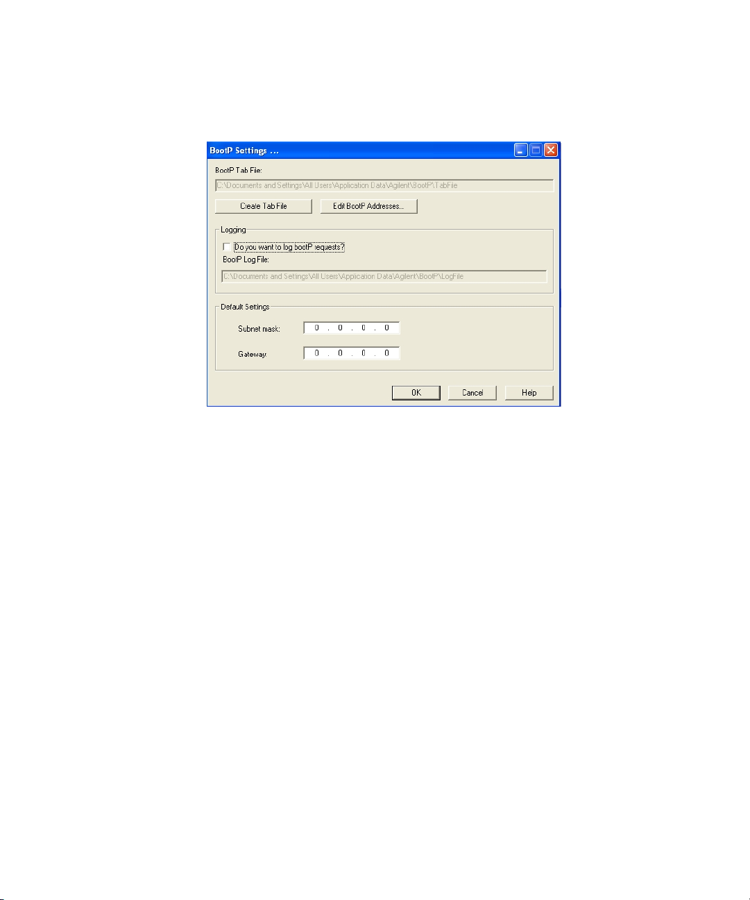
11 Files load; when finished, the BootP Settings screen appears.
Figure 19 BootP Settings screen
12 In the Default Settings part of the screen, if known, you can enter the subnet
mask and gateway.
Defaults can be used:
• The default subnet mask is 255.255.255.0.
• The default gateway is 10.1.1.101.
13 On the BootP Settings screen, click OK. The Agilent BootP Service Setup screen
indicates completion.
14 Click Finish to exit the Agilent BootP Service Setup screen.
15 Remove the DVD from the drive.
This completes installation.
16 Start the BootP service. On the Windows® desktop, select Start > Control
Panel > Services. Select the Agilent BootP Service and click Start.
4
Agilent 1260 Infinity DAD and MWD User Manual 69
Page 70

4 LAN Configuration
Automatic Configuration with BootP
Two Methods to Determine the MAC Address
Enabling logging to discover the MAC address using BootP
If you want to see the MAC address, select the Do you want to log BootP requests?
check box.
1 Open BootP Settings from Start > All Programs > Agilent BootP Service >
EditBootPSettings.
2 In BootP Settings... check Do you want to log BootP requests? to enable logging.
Figure 20 Enable BootP logging
The log file is located in
C:\Documents and Settings\All Users\Application Data\Agilent\BootP\LogFile
It contains a MAC address entry for each device that requests configuration
information from BootP.
3 Click OK to save the values or Cancel to discard them. The editing ends.
4 After each modification of the BootP settings (i.e. EditBootPSettings) a stop
or start of the BootP service is required for the BootP service to accept
changes. See “Stopping the Agilent BootP Service” on page 74 or “Restarting
the Agilent BootP Service” on page 75.
5 Uncheck the Do you want to log BootP requests? box after configuring
instruments; otherwise, the log file will quickly fill up disk space.
Determining the MAC address directly from the LAN Interface card label
1 Turn off the instrument.
2 Read the MAC address from the label and record it.
The MAC address is printed on a label on the rear of the module. It is the
number below the barcode and after the colon (:) and usually begins with
the letters AD, see Figure 12 on page 58 and Figure 13 on page 58.
3 Turn on the instrument.
70 Agilent 1260 Infinity DAD and MWD User Manual
Page 71

LAN Configuration
Automatic Configuration with BootP
Assigning IP Addresses Using the Agilent BootP Service
The Agilent BootP Service assigns the Hardware MAC address of the
instrument to an IP address.
Determining the MAC address of the instrument using BootP Service
1 Power cycle the Instrument.
2 After the instrument completes self-test, open the log file of the BootP
Service using Notepad.
• The default location for the logfile is C:\Documents and Settings\All Users\
Application Data\Agilent\BootP\LogFile.
• The logfile will not be updated if it is open.
The contents will be similar to the following:
02/25/10 15:30:49 PM
Status: BootP Request received at outermost layer
Status: BootP Request received from hardware address: 0010835675AC
4
Error: Hardware address not found in BootPTAB: 0010835675AC
Status: BootP Request finished processing at outermost layer
3 Record the hardware (MAC) address (for example, 0010835675AC).
4 The Error means the MAC address has not been assigned an IP address and
the Tab File does not have this entry. The MAC address is saved to the Tab
File when an IP address is assigned.
5 Close the log file before turning on another instrument.
6 Uncheck the Do you want to log BootP requests? box after configuring
instruments to avoid having the logfile use up excessive disk space.
Agilent 1260 Infinity DAD and MWD User Manual 71
Page 72
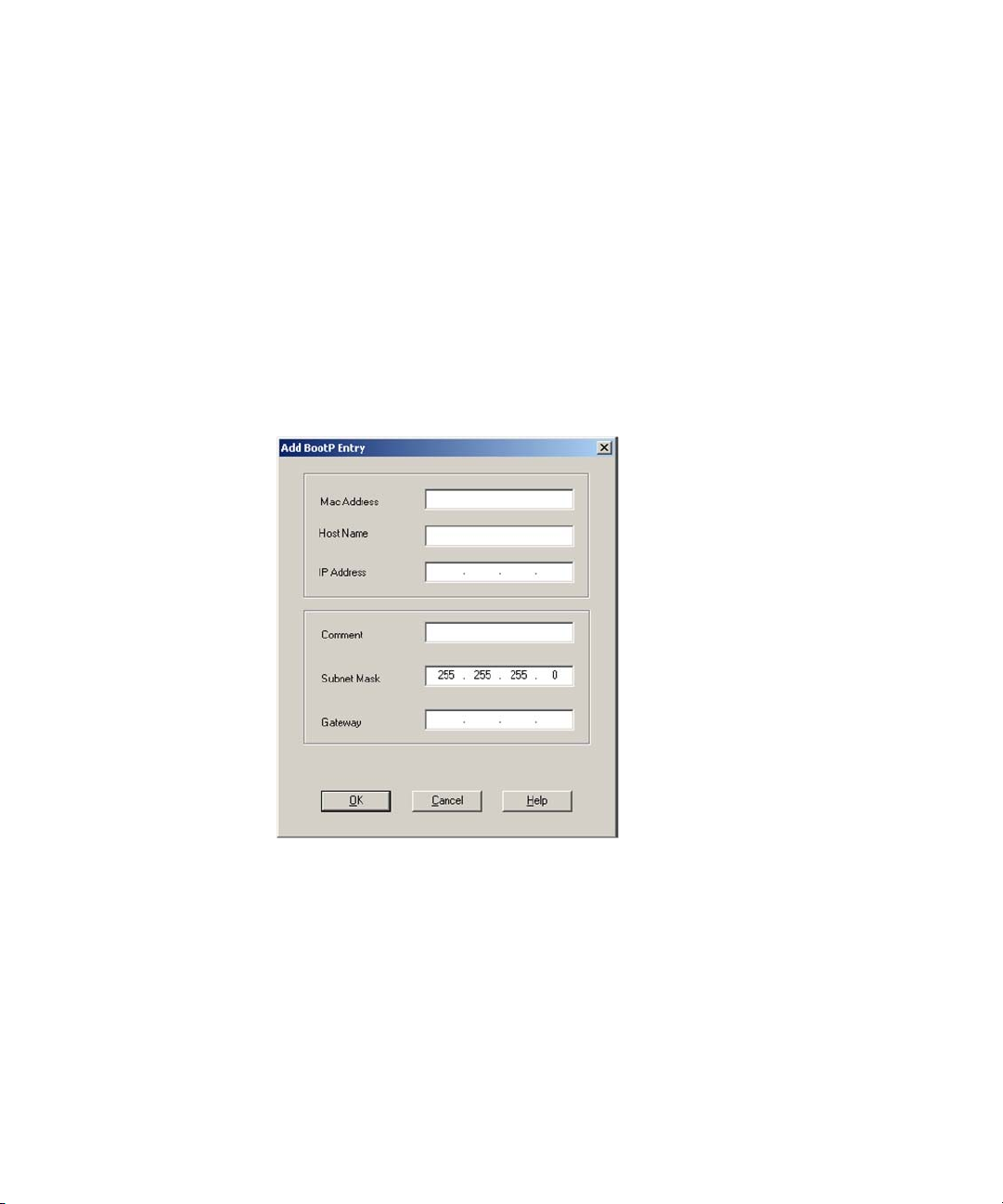
4 LAN Configuration
Automatic Configuration with BootP
Adding each instrument to the network using BootP
1 Follow Start > All Programs > Agilent BootP Service and select Edit BootP
Settings. The BootP Settings screen appears.
2 Uncheck the Do you want to log BootP requests? once all instruments have been
added.
The Do you want to log BootP requests? box must be unchecked when you have
finished configuring instruments; otherwise, the log file will quickly fill up
disk space.
3 Click Edit BootP Addresses... The Edit BootP Addresses screen appears.
4 Click Add... The Add BootP Entry screen appears.
Figure 21 Enable BootP logging
72 Agilent 1260 Infinity DAD and MWD User Manual
Page 73

LAN Configuration
Automatic Configuration with BootP
5 Make these entries for the instrument:
• MAC address
• Host name, Enter a Hostname of your choice.
The Host Name must begin with "alpha" characters (i.e. LC1260)
• IP address
• Comment (optional)
• Subnet mask
• Gateway address (optional)
The configuration information entered is saved in the Tab File.
6 Click OK.
7 Leave Edit BootP Addresses by pressing Close.
8 Exit BootP Settings by pressing OK.
9 After each modification of the BootP settings (i.e. EditBootPSettings) a stop
or start of the BootP service is required for the BootP service to accept
changes. See “Stopping the Agilent BootP Service” on page 74 or “Restarting
the Agilent BootP Service” on page 75.
10 Power cycle the Instrument.
OR
If you changed the IP address, power cycle the instrument for the changes
to take effect.
11 Use the PING utility to verify connectivity by opening a command window
and typing:
Ping 10.1.1.101 for example.
The Tab File is located at
C:\Documents and Settings\All Users\Application Data\Agilent\BootP\TabFile
4
Agilent 1260 Infinity DAD and MWD User Manual 73
Page 74

4 LAN Configuration
Automatic Configuration with BootP
Changing the IP Address of an Instrument Using the Agilent BootP Service
Agilent BootP Service starts automatically when your PC reboots. To change
Agilent BootP Service settings, you must stop the service, make the changes,
and then restart the service.
Stopping the Agilent BootP Service
1 From the Windows control panel, select Administrative Tools > Services. The
Services screen appears.
Figure 22 Windows Services screen
2 Right-click Agilent BootP Service.
3 Select Stop.
4 Close the Services and Administrative Tools screen.
74 Agilent 1260 Infinity DAD and MWD User Manual
Page 75

LAN Configuration
Automatic Configuration with BootP
Editing the IP address and other parameters in EditBootPSettings
1 Select Start > All Programs > Agilent BootP Service and select Edit BootP Settings.
The BootP Settings screen appears.
2 When the BootP Settings screen is first opened, it shows the default settings
from installation.
3 Press Edit BootP Addresses… to edit the Tab File.
Figure 23 Edit BootP Adresses screen
4 In the Edit BootP Addresses... screen press Add... to create a new entry or
select an existing line from the table and press Modify... or Delete to change
the IP address, comment, subnet mask, for example, in the Tab File.
If you change the IP address, it will be necessary to power cycle the
instrument for the changes to take effect.
5 Leave Edit BootP Addresses... by pressing Close.
6 Exit BootP Settings by pressing OK.
4
Restarting the Agilent BootP Service
1 In the Windows control panel, select Administrative Tools > Services. The
Services screen appears, see Figure 22 on page 74.
2 Right-click Agilent BootP Service and select Start.
3 Close the Services and Administrative Tools screens.
Agilent 1260 Infinity DAD and MWD User Manual 75
Page 76

4 LAN Configuration
Storing the settings permanently with Bootp
Storing the settings permanently with Bootp
If you want to change parameters of the module using the Bootp follow the
instructions below.
1 Turn off the module.
2 Change the module's settings of the Configuration Switch to “Bootp &
Store” mode, see Table 16 on page 61.
3 Start the Agilent Bootp Service and open its window.
4 If required, modify the parameters for the module according to your needs
using the existing configuration.
5 Press OK to exit the Bootp Manager.
6 Now turn on the module and view the Bootp Server window. After some
time the Agilent Bootp Service will display the request from the LAN
interface. The parameters are now stored permanently in the non-volatile
memory of the module.
7 Close the Agilent Bootp Service and turn off the module.
8 Change the settings of the module’s Configuration Switch to “Using Stored”
mode, see Table 16 on page 61.
9 Power cycle the module. The module can be accessed now via LAN without
the Agilent Bootp Service.
76 Agilent 1260 Infinity DAD and MWD User Manual
Page 77

Manual Configuration
Manual configuration only alters the set of parameters stored in the
non-volatile memory of the module. It never affects the currently active
parameters. Therefore, manual configuration can be done at any time. A
power cycle is mandatory to make the stored parameters become the active
parameters, given that the initialization mode selection switches are allowing
it.
I:AC:I
HZhh^dc
Manual Configuration
Cdc"KdaVi^aZ
G6B
HidgZY
EVgVbZiZg
LAN Configuration
4
8dcigda
BdYjaZ
Figure 24 Manual Configuration (Principle)
Agilent 1260 Infinity DAD and MWD User Manual 77
Page 78

4 LAN Configuration
Manual Configuration
With Telnet
Whenever a TCP/IP connection to the module is possible (TCP/IP parameters
set by any method), the parameters may be altered by opening a Telnet
session.
1 Open the system (DOS) prompt window by clicking on Windows START
2 Type the following at the system (DOS) prompt:
button and select “Run...”. Type “cmd” and press OK.
• c:\>telnet <IP address> or
• c:\>telnet <host name>
Figure 25 Telnet - Starting a session
where <IP address> may be the assigned address from a Bootp cycle, a
configuration session with the Handheld Controller, or the default IP
address (see “Configuration Switch” on page 60).
When the connection was established successfully, the module responds
with the following:
Figure 26 A connection to the module is made
78 Agilent 1260 Infinity DAD and MWD User Manual
Page 79

LAN Configuration
Manual Configuration
3 Type
? and press enter to see the available commands.
Figure 27 Telnet Commands
Ta bl e 1 9 Telnet Commands
Value Description
? displays syntax and descriptions of commands
/ displays current LAN settings
ip <x.x.x.x> sets new ip address
4
sm <x.x.x.x> sets new subnet mask
gw <x.x.x.x> sets new default gateway
exit exits shell and saves all changes
4 To change a parameter follows the style:
• parameter value, for example:
ip 134.40.27.230
Then press [Enter], where parameter refers to the configuration parameter
you are defining, and value refers to the definitions you are assigning to
that parameter. Each parameter entry is followed by a carriage return.
Agilent 1260 Infinity DAD and MWD User Manual 79
Page 80

4 LAN Configuration
Manual Configuration
5 Use the “/” and press Enter to list the current settings.
Figure 28 Telnet - Current settings in "Using Stored" mode
6 Change the IP address (in this example 134.40.27.99) and type “/” to list
current settings.
information about the LAN interface
MAC address, initialization mode
Initialization mode is Using Stored
active TCP/IP settings
TCP/IP status - here ready
connected to PC with controller software (e.g. Agilent
ChemStation), here not connected
change of IP setting to
Initialization mode is Using Stored
active TCP/IP settings
stored TCP/IP settings in non-volatile memory
connected to PC with controller software (e.g. Agilent
ChemStation), here not connected
Figure 29 Telnet - Change IP settings
80 Agilent 1260 Infinity DAD and MWD User Manual
Page 81

LAN Configuration
Manual Configuration
7 When you have finished typing the configuration parameters, type
exit and press Enter to exit with storing parameters.
Figure 30 Closing the Telnet Session
4
NOTE
If the Initialization Mode Switch is changed now to “Using Stored” mode, the instrument
will take the stored settings when the module is re-booted. In the example above it would
be 134.40.27.99.
Agilent 1260 Infinity DAD and MWD User Manual 81
Page 82

4 LAN Configuration
Manual Configuration
With the Instant Pilot (G4208A)
To configure the TCP/IP parameters before connecting the module to the
network, the Instant Pilot (G4208A) can be used.
1 From the Welcome screen press the More button.
2 Select Configure.
3 Press the DAD button.
4 Scroll down to the LAN settings.
Figure 31 Instant Pilot - LAN Configuration
5 Press the Edit button (only visible if not in Edit mode), perform the required
changes and press the Done button.
6 Leave the screen by clicking Exit.
82 Agilent 1260 Infinity DAD and MWD User Manual
Page 83

Agilent 1260 Infinity DAD and MWD User Manual
5
Using the Detector
Setting up an Analysis 84
Before Using the System 84
Requirements and Conditions 86
Optimization of the System 89
Preparing the HPLC System 90
Running the Sample and Verifying the Results 99
Special Settings of the Detector 100
Control Settings 100
Configuration Settings 101
Online Spectra (DAD only) 102
Run Recovery Settings 103
Automated Run Recovery in case of temporary communication
failures 104
Manual Run Recovery in case of permanent communication
failures 106
Analog Output Settings 107
Spectrum Settings (DAD only) 108
Peakwidth Settings 110
Slit Settings 112
Margin for Negative Absorbance Settings 113
Optimizing the Detector 113
Special Setups with Multiple DAD-MWDs 114
Two detectors of same type (e.g. G1315C/D and G1315C/D) 114
Two detectors of similar type (e.g. G1315C/D and G1315A/B) 114
This chapter provides information on how to set up the detector for an analysis
and explains the basic settings.
Agilent Technologies
83
Page 84

5 Using the Detector
Setting up an Analysis
Setting up an Analysis
This chapter may be used to
• Prepare the system,
• Get to know the set up of an HPLC analysis and
• Use it as an instrument check to demonstrate that all modules of the system
are correctly installed and connected. It is not a test of the instrument
performance.
• Learn about special settings
Before Using the System
Solvent Information
Observe recommendations on the use of solvents in chapter “Solvents”.
Priming and Purging the System
When the solvents have been exchanged or the pumping system has been
turned off for a certain time (for example, overnight) oxygen will re-diffuse
into the solvent channel between the solvent reservoir, vacuum degasser
(when available in the system) and the pump. Volatile ingredients will
evaporate to some extend. Therefore priming of the pumping system is
required before starting an application.
84 Agilent 1260 Infinity DAD and MWD User Manual
Page 85

Ta bl e 2 0 Choice of Priming Solvents for Different Purposes
Activity Solvent Comments
Using the Detector
Setting up an Analysis
5
After an installation
When switching between reverse
phase and normal phase (both times)
After an installation Ethanol or Methanol Alternative to Isopropanol (second
Cleaning the system when using
buffers
After a solvent change
After the installation of normal phase
seals (P/N 0905-1420)
NOTE
The pump should never be used for priming empty tubings (never let the pump run dry). Use
a syringe to draw enough solvent to completely fill the tubings up to the pump inlet before
Isopropanol
Isopropanol
Bidistilled water
Bidistilled water
Hexane + 5% Isopropanol Good wetting properties
Best solvent to flush air out of the
system
Best solvent to flush air out of the
system
choice) if no Isopropanol is available
Best solvent to re-dissolve buffer
crystals
Best solvent to re-dissolve buffer
crystals
you continue priming with the pump.
1 Open the purge valve of your pump (by turning it counterclockwise) and set
flow rate to 3-5 ml/min.
2 Flush all tubes with at least 30 ml of solvent.
3 Set flow to required value of your application and close the purge valve.
Pump for approximately 10 minutes before starting your application.
Agilent 1260 Infinity DAD and MWD User Manual 85
Page 86

5 Using the Detector
Setting up an Analysis
Requirements and Conditions
Parts and Material required
Table 21 on page 86 lists the parts and material you need for the set up of the
analysis. Some of these are optional (not required for the basic system).
Ta bl e 2 1 Parts and Material required
Agilent 1260
Infinity system
Column: Zorbax Eclipse XDB C18, 150 mm x 4.6 mm, 5 µm (p/n 993967-906)
Standard: Agilent isocratic checkout sample (p/n 01080-68704). This 0.5 mL
Pump (plus degassing)
Autosampler
Detector, standard flow cell installed
• Agilent ChemStation or
• Instant Pilot G4208 (optional for basic operation) or
with with the appropriate revisions, see “Performance Specifications” on
page 38.
System should be correctly set up for LAN communication with the Data
System
ampoule contains 0.15 wt.% dimethylphthalate, 0.15 wt.% diethylphthalate,
0.01 wt.% biphenyl, 0.03 wt.% o-terphenyl in methanol.
86 Agilent 1260 Infinity DAD and MWD User Manual
Page 87

Using the Detector
Setting up an Analysis
Conditions
A single injection of the isocratic test standard is made under the conditions
given in Table 22 on page 87:
Ta bl e 2 2 Conditions
Flow 1.5 ml/minute
Stoptime 8 minutes
Solvent 100% (30% water/70% Acetonitrile)
Temperature Ambient
Wavelength sample 254 nm (4 nm bandwidth) reference 360 nm (100 nm bandwidth)
Injection Volume 1 µl
5
Agilent 1260 Infinity DAD and MWD User Manual 87
Page 88

5 Using the Detector
Setting up an Analysis
Typical Chromatogram
A typical chromatogram for this analysis is shown in Figure 32 on page 88.
The exact profile of the chromatogram will depend on the chromatographic
conditions. Variations in solvent quality, column packing, standard
concentration and column temperature will all have a potential effect on peak
retention and response.
Figure 32 Typical Chromatogram with UV-detector
88 Agilent 1260 Infinity DAD and MWD User Manual
Page 89

Optimization of the System
The settings used for this analysis are specific for this purpose. For other
applications the system can be optimized in various ways. Please refer to the
section “Optimizing the Detector” on page 113.
Using the Detector
Setting up an Analysis
5
Agilent 1260 Infinity DAD and MWD User Manual 89
Page 90

5 Using the Detector
Setting up an Analysis
Preparing the HPLC System
1 Turn on the Agilent ChemStation PC and the monitor.
2 Turn on the HPLC modules.
3 Start the Agilent ChemStation software. If the pump, autosampler,
HnhiZbhiVijh
thermostatted column compartment and detector are found, the
ChemStation screen should look like shown in Figure below.
The System status is red (Not Ready).
Dc"a^cZeadil^cYdl
YZiV^ahl^cYdl
Figure 33 Initial ChemStation screen (Method and Run Control)
90 Agilent 1260 Infinity DAD and MWD User Manual
Page 91
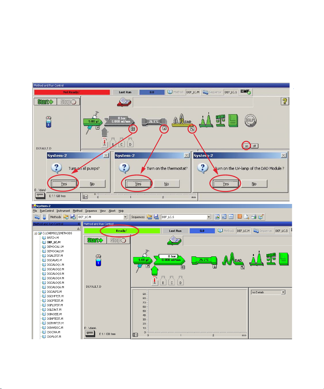
Using the Detector
Setting up an Analysis
4 Turn on the detector lamp, pump and autosampler by clicking the System On
button or the buttons below the module icons on the graphical user
interface (GUI). After some time, the pump, thermostatted column
compartment and detector module will turn to green.
5
Figure 34 Turning on the HPLC Module
Agilent 1260 Infinity DAD and MWD User Manual 91
Page 92
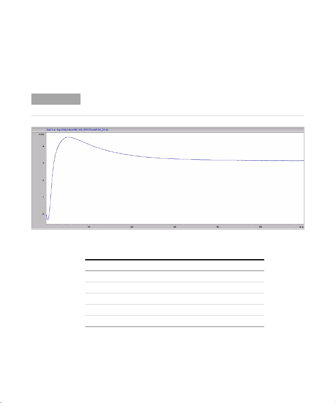
5 Using the Detector
Setting up an Analysis
5 Purge the pump. For more information see “Priming and Purging the
6 Allow the detector to warm up at least 60 minutes to provide a stable
System” on page 84.
baseline (see example in Figure 35 on page 92 and Table 23 on page 92).
NOTE
For reproducible chromatography, the detector and lamp should be on for at least one hour.
Otherwise the detector baseline may still drift (depending on the environment). See also
section Wander/Drift Problems Due to Temperature Changesin the Service Manual..
Figure 35 Stabilization of Baseline (both lamps turned on at the same time)
Ta bl e 2 3 Baseline drift after lamp turn on (example from Figure above)
Time [minutes] Drift [mAU/hr]
17 - 20 2.6
27 - 30 0.8
37 - 40 0.4
47 - 50 0.2
57 - 60 < 0.2
92 Agilent 1260 Infinity DAD and MWD User Manual
Page 93

Using the Detector
Setting up an Analysis
7 For the isocratic pump, fill the solvent bottle with the mixture of
HPLC-grade bi-distilled water (30 %) and acetonitrile (70 %). For binaryand quaternary pumps you can use separate bottles.
8 Click on the Load Method button and select DEF_LC.M and press OK.
Alternative double-click on the method in the method window. The default
LC method parameters are transferred into the modules.
5
Figure 36 Loading Default LC Method
Agilent 1260 Infinity DAD and MWD User Manual 93
Page 94

5 Using the Detector
Setting up an Analysis
9 Click on the module icons (see Figure below) and open the Setup of these
modules. Figure on page 95 shows the detector settings (do not change the
detector parameters at this time).
Figure 37 Open the module menu
94 Agilent 1260 Infinity DAD and MWD User Manual
Page 95

Using the Detector
Setting up an Analysis
10 Enter the pump parameters mentioned under Table 22 on page 87.
• up to 8 signals (A to H) with individual wavelength
settings can be selected.
• spectrum settings, “Spectrum Settings (DAD only)” on
page 108
• stop and post time can be set (if required)
• depending on the application, the lamps can be
selected (one or both).
• peak width depends on the peaks in the chromatogram,
“Peakwidth Settings” on page 110
• autobalance to zero absorbance (on the analog output
plus offset) at begin and/or end of run.
• mechanical slit width can be changed for further
optimization, “Slit Settings” on page 112
• margin for negative absorbance, “Margin for Negative
Absorbance Settings” on page 113
• Under More additional diagnostic signals can be added
for troubleshooting purpose, see section “Diagnostic
Signals“ in the Service Manual.
• time table for programmable actions during the run.
NOTE: The Agilent G1315C/D and G1365C/D time
table can contain a maximum of 60 rows.
5
11 Pump the water/acetonitrile (30/70 %) mobile phase through the column for
10 minutes for equilibration.
Agilent 1260 Infinity DAD and MWD User Manual 95
Page 96

5 Using the Detector
Setting up an Analysis
12 Click the button and select Change... to open the Signal Plot information.
Select the Pump: Pressure and the DAD A: Signal 254,4 as signals. Change the
Y-range for the DAD to 1 mAU and the offset to 20% and the pressure offset
to 50%. The X-axis range should be 15 minutes. Press OK to exit this screen.
Figure 38 Edit Signal Plot Window
The Online Plot (Figure 39 on page 97) shows both, the pump pressure and
the detector absorbance signals. Pressing Adjust the signals can be reset to
the offset value and Balance would do a balance on the detector.
96 Agilent 1260 Infinity DAD and MWD User Manual
Page 97

Using the Detector
Setting up an Analysis
EjbeegZhhjgZh^\cVa
969VWhdgWVcXZh^\cVa
Figure 39 Online Plot Window
13 If both baselines are stable, set the Y-range for the detector signal to
100 mAU.
5
NOTE
Agilent 1260 Infinity DAD and MWD User Manual 97
If you start with a new UV-lamp for the first time, the lamp may show initial drift for some
time (burn-in effect).
Page 98
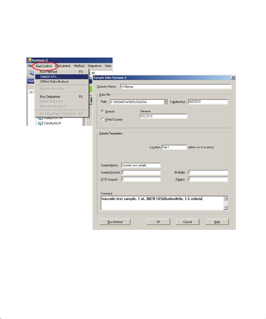
5 Using the Detector
Setting up an Analysis
14 Select the menu item RunControl -> Sample Info and enter information about
this application (see figure below). Press OK to leave this screen.
Figure 40 Sample Information
15 Fill the content of an isocratic standard sample ampoule into a vial and seal
the vial with a cap and place the vial into autosampler tray (position #1).
98 Agilent 1260 Infinity DAD and MWD User Manual
Page 99
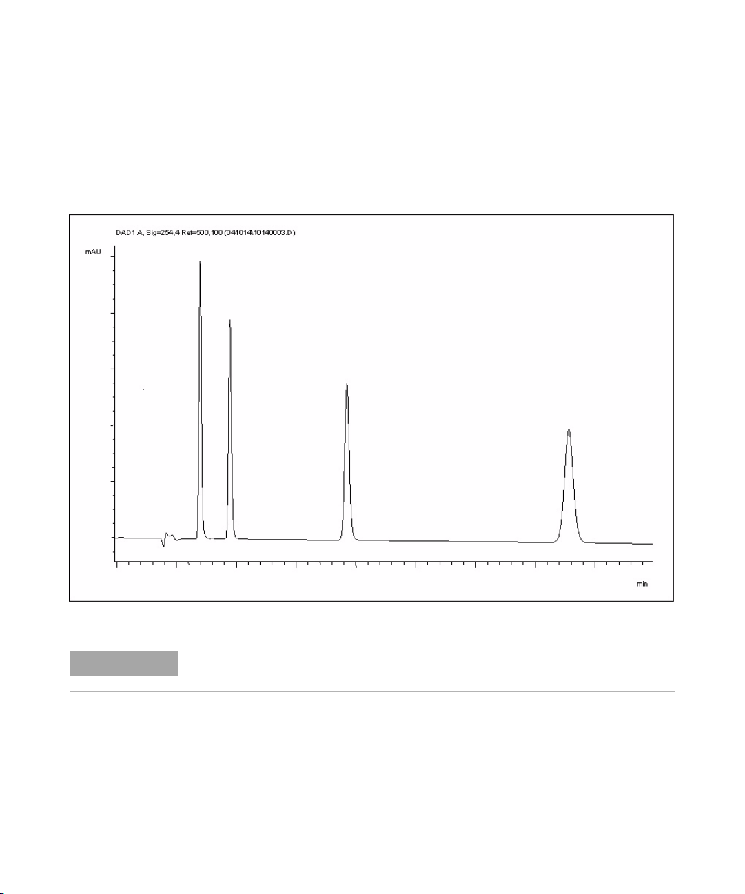
Running the Sample and Verifying the Results
1 To start a run select the menu item RunControl -> Run Method.
2 This will start the modules and the online plot on the Agilent ChemStation
will show the resulting chromatogram.
Using the Detector
Setting up an Analysis
5
Figure 41 Chromatogram with Isocratic Test Sample
NOTE
Agilent 1260 Infinity DAD and MWD User Manual 99
Information about using the Data Analysis functions can be obtained from the Using your
ChemStation manual supplied with your system.
Page 100
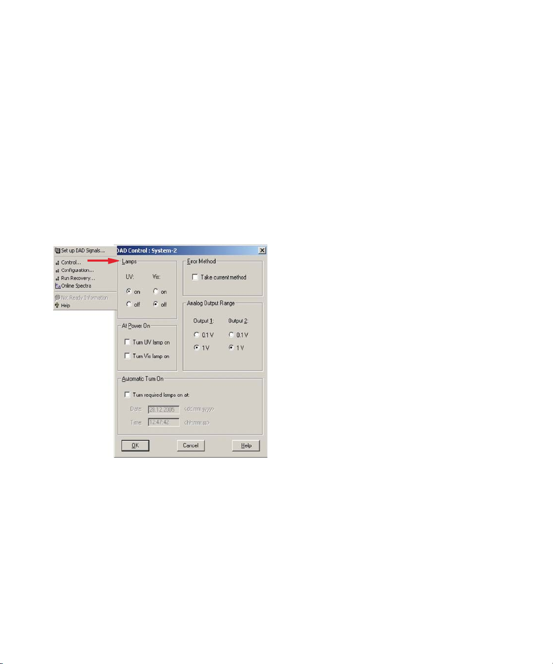
5 Using the Detector
Special Settings of the Detector
Special Settings of the Detector
In this chapter special settings of the G1315C/D and G1365C/D are described
(based on the Agilent ChemStation B.02.01).
Control Settings
•Lamps: turn on and off of UV- and Vis lamp
•At Power On: automatic lamp-on at power on.
• Error Method: take error method or current method (in
case of an error)
• Analog Output Range: can be set to either 100 mV or 1
V full scale, “Analog Output Settings” on page 107
• Automatic Turn On: lamps can be programmed
(detector must be on for this).
•Help: online help.
Figure 42 Detector control settings
100 Agilent 1260 Infinity DAD and MWD User Manual
 Loading...