

Page 1

User
,
Programming and
Service Guide
Agilent
11896A
Polarization Controller
Page 2

Notice
The
information
notice
contained
in
this
document
is
subject
to
change
without
.
Agilent
this
T
echnologies
material,
merchantability
shall
not
be
liable
consequential
of
this
material.
Agilent
Printed
P
in
art
Number:
US
A
makes
including,
and
tness
for
errors
damages
April
2000
no
warranty
but
not
limited
for
a
contained
in
connection
11896-90011
to
particular
herein
with
of
any
,
the
purpose
the
kind
with
implied
.
Agilent
or
for
incidental or
furnishing,
regard
warranties
T
echnologies
performance
to
of
,
or
use
c
Copyright Agilent T
echnologies 2000
All Rights Reserved. Reproduction, adaptation, or translation without prior
written permission is prohibited, except as allowed under the copyright laws
1400 F
ountaingrove P
arkway, Santa Rosa, CA 95403-1799, US
A
.
Page 3

Certication
Agilent
at
certies
National
the
International
Technologies
the time
of
shipment
that its
Institute of
Institute's calibration
Standards
certies
from
that
the
this
factory
product
.
calibration measurements
Standards and
facility,
Organization
T
echnology
and
to
members
Agilent
are
the
calibration
met
its
T
echnologies
traceable
,
to
the
.
published
to
the
extent
allowed
facilities
specications
further
United
States
by
of
other
iii
Page 4

W
arranty
This
Agilent T
material
During
repair
F
or warranty
facility
charges
charges
charges
another
and workmanship
the warranty
or replace
designated
to
to
, duties
country
echnologies
products which
service or
Agilent
return
,
the
and
.
instrument
for
period, Agilent
repair
by
Agilent
T
echnologies
product
taxes
for
product
a
period
T
echnologies
prove
,
this
product
T
echnologies
and
Agilent
to
Buyer
.
products
of
one
to
be
defective
must
.
Buyer
T
echnologies
However
returned
is
warranted
year
from
will,
be
shall
,
Buyer
to
Agilent
against
date
at
its
.
returned
prepay
shall
shall
T
defects
of
shipment.
option,
to
a
service
either
shipping
pay
shipping
pay
all
shipping
echnologies
in
from
Agilent T
Agilent T
instructions when
does not
rmware
Limit
The
or
interfacing,
environmental
or
NO
TECHNOLOGIES
OF
Ex
THE
REMEDIES
ANY
echnologies warrants
echnologies for
warrant that
will
be uninterrupted
a
tion
of
W
foregoing
inadequate
unauthorized
maintenance
OTHER
W
ARRANTY
MERCHANT
clusive
Remedies
REMEDIES
.
A
GILENT TECHNOLOGIES
DIRECT, INDIRECT
properly installed
arranty
warranty
maintenance
specications
.
SPECIFICALL
ABILITY
PRO
DAMAGES, WHETHER B
LEGAL THEORY
.
use
that its
with
software
an
instrument
on
the
operation
shall
by
or
not
Buyer
of
error-free
apply
modication
for
the
IS
EXPRESSED
Y
DISCLAIMS
AND
FITNESS
VIDED HEREIN
, SPECIAL, INCIDENT
ASED ON CONTRA
and
will
that
instrument.
the
instrument,
.
to
defects
,
Buyer-supplied
or
misuse
,
product,
OR
or
improper
IMPLIED
THE
FOR
A
P
ARTICULAR
ARE BUYER'S
SHALL
NOT
AL, OR CONSEQUENTIAL
CT
, TORT
rmware
execute
designated
its
programming
Agilent
or
software
resulting
from
software
operation
.
IMPLIED
A
GILENT
outside
site
preparation
W
ARRANTIES
PURPOSE.
SOLE AND
BE
LIABLE
, OR ANY OTHER
by
T
echnologies
,
or
improper
or
of
the
EXCLUSIVE
FOR
iv
Page 5

Assistance
Product
are
available for
F
or any
maintenance agreements
A
gilent
T
echnologies
assistance,
contact
your
and
products.
nearest
other
A
customer
gilent
assistance
T
echnologies
agreements
Service
Oce
.
v
Page 6

C
W
AU
A
Safety
The
following safety
yourself
Symbols
with each
symbols
of
the
are
symbols
used
and
throughout
its
meaning
this
before
manual.
operating
F
amiliarize
this
instrument.
The
TI
O
N
caution
procedure
damage
sign
until
The
R
N
I
N
G
warning
procedure
in
injury
indicated
sign
which, if
to
or
destruction
the
indicated
sign
which, if
or
loss
conditions
denotes a
not correctly
conditions
denotes
not
of
life
.
are
hazard
performed
of
the
instrument.
a
life-threatening
correctly
Do
not
proceed
fully
understood
to
the
instrument.
are
fully
performed
beyond
or
adhered
Do
not
proceed
understood
hazard.
or
adhered
a
warning
and
met.
It
calls
to
and
It
,
could
met.
calls
to
attention
beyond
,
could
sign
to
result
in
a
caution
attention to
result
until the
a
a
Instruction
Manual
L
vi
The
instruction
for
the
user
to
manual
refer
to
symbol.
the
The
instructions
product is
in
the
marked
manual.
with
this
symbol
when
it
is
necessary
Page 7

General
Safety Considerations
W
A
R
N
I
N
G
Before
grounded
socket
Any
outside
can
W
AR
N
I
N
G
This
ground
inserted
Any
instrument is
interruption is
W
A
R
N
I
N
G
There
personal
Any
instrument
trained
W
A
R
N
I
N
G
If
equipment
condition
this
through
outlet
interruption
the
result
is
a
Safety
in
incorporated in
in
interruption
are
many
injury
adjustments
service
this
instrument
(in
instrument
the
provided
of
the
instrument,
personal
Class
a
socket
of
outlet
the
likely to
prohibited.
points
.
Be
extremely
or
service
with
protective
personnel.
is not
could
be
impaired. This
which
all
is
switched
protective
with
protective
protective
or
disconnection
injury
.
I
product
the
power
provided
protective
make the
in
the
procedures
covers
used as
means
on
,
conductor
(grounding)
(provided
cord).
with a
conductor
instrument
instrument
careful.
removed
specied,
instrument must
for
protection
make
sure
of
the
earth
contact.
conductor
of
the
protective
with
a
protective
The
mains
protective earth
inside or
dangerous
which
that
can,
require
should
the
protection
are
intact)
it
has
ac
power
plug
outside of
.
Intentional
if
contacted,
operation
be
performed
be
used
only
been
properly
cable
,
inside
earth
earthing
shall
only
contact.
of
provided
in
.
to
a
or
terminal
be
the
cause
the
only
by
a
normal
by
the
N
O
Clean
T
E
the
cabinet
using
a
damp cloth
only.
vii
Page 8

How
This
manual provides
controller
.
to Use
This Manual
information
about
the
Agilent
11896A
polarization
Chapter
Chapter
Chapter
Chapter
Chapter 5
Appendix
Appendix
Appendix
1
provides
general information
and
specications
for
the
controller
2
3
describes
use
and
shows
how
how
how
to
to
make
to
manually
prepare
ber
the
optic
control
polarization
connections
the
lightwave
controller
polarization
for
controller
4
A
B
C
shows
using a
how
to
computer
control
provides procedures
Agilent 11896A
selecting scan
measurement
provides
a
polarization controller
rate
considerations
sample
the lightwave
for
verifying
and
measurement
GPIB
program
polarization controller
and
servicing
the
time
viii
Page 9
Contents
1.
General
Description
Instrumen
P
Theory of
Sp
ecications
Serial
Electrostatic
Reducing
2.
Installation
Preparing
Initial
Connecting
P
Chec
P
T
urning on
Ligh
In
Cleaning
Cleaning non-lensed light
Cleaning light
Cleaning lensed connections
Information
.
.
.
.
.
.
.
.
.
.
.
.
.
.
.
.
.
t
conguration
Options
Accessories
olarization-dep
P
o
w
Sw
ept-w
Max/min
Num
o
w
er requiremen
king
o
w
er
tw
a
v
troduction
Denition
Handling
Cleaning
Equipment . . . . . . . . . . . . . . . . .
Process . . . . . . . . . . . . . . . . . .
Equipment . . .
Process
.
er
meter
a
v
elength
PDL
Operation
and
b
ers
Disc
ESD
and
Preparation
the
P
olarization
insp
ection
the
the
fuse
cable
.
the
Agilen
e
Connector
and handling
of terms
.
.
w
. . . .
.
.
.
.
.
.
enden
PDL
measuremen
.
Characteristics
.
.
.
harge
damage
.
Agilen
ts .
.
.
.
.
t
Care
.
.
.
.
.
.
.
.
.
ave adapters
.
.
.
.
.
.
.
.
.
.
.
.
.
.
.
.
.
.
.
.
.
.
.
.
.
.
.
.
.
.
.
.
.
.
t
loss
measuremen
measuremen
PDL
measuremen
.
.
.
.
.
.
Information
.
.
Controller
.
. .
t
11896A
. .
. .
. .
.
.
.
11896A
.
.
.
.
. .
. .
.
.
.
.
.
.
wave connectors .
. . . . . . . . . . . . . . . .
. . . . . . . . . . . . . . . .
t
t
system
.
.
.
.
.
.
.
.
.
.
for
Use
.
.
.
to a
.
.
.
.
.
.
.
.
.
.
.
.
.
.
.
.
.
.
.
.
.
.
.
.
.
.
.
.
. . . . . . . . . . . .
. . . .
ts
system
t
system
.
.
.
.
.
.
.
.
.
.
.
.
.
.
.
.
.
.
.
.
.
.
for
Use
.
.
.
.
p
o
w
er
source
.
.
.
.
.
.
.
.
.
.
.
.
.
.
.
.
.
.
.
.
.
.
.
.
.
.
.
.
.
.
.
.
.
.
.
. .
.
. .
. .
. . . . . . . .
.
.
.
.
.
.
.
.
.
.
. .
.
.
.
.
.
.
.
.
.
.
.
.
.
.
.
.
.
.
.
.
.
.
.
.
. .
. .
. . . . . .
. .
.
.
.
.
.
.
.
.
.
. .
.
.
.
.
.
.
.
.
.
.
.
.
.
. .
.
.
.
.
.
.
.
.
.
.
.
.
.
.
. .
.
.
.
.
.
. .
. .
. .
.
. .
.
.
.
.
.
.
.
.
.
.
.
.
.
.
.
. .
.
.
.
. .
. .
1-3
.
1-4
.
1-4
1-4
.
1-5
.
1-5
.
1-6
.
1-8
.
1-10
.
1-11
.
1-14
.
1-15
.
1-17
.
2-3
.
2-3
.
2-4
.
2-4
.
2-4
.
2-5
.
2-8
2-9
.
2-9
.
2-11
.
2-11
.
2-11
.
2-11
2-12
2-12
2-12
2-13
2-13
2-13
2-13
Contents-1
Page 10
Storage
Making
Summary
Insp
Visual
Optical
In
Insertion
Return
3.
Using
4.
Programming
the
F
ron
t-P
Error
Rear-P
Using
P
o
w
T
o
use
T
o
con
T
o
set
T
o
sa
T
o
recall
To
use
T
o
displa
Changing
T
alking
Program Message
Output
Device
Instructions
Instruction
White space
Program
Header t
Simple command header
Compound command header
Common command header
Combining commands
Duplicate mnemonics
Query command
.
.
.
connections
.
.
.
ection
tro
anel
anel
the
er-up function
v
to
.
.
insp
ection
p
erformance
duction
loss
loss
.
Agilent
co
F
Agilen
the
tin
uously
the
e
an
an
the
y
the
command
address
data
yp
11896A
F
eatures
des
.
eatures
t 11896A
Man
ual
sw
scan
rate
instrumen
instrumen
Lo
cal
or
c
hange
the
GPIB
Instrumen
Syntax
.
. .
header
(separator) .
.
es . . . . . . . . . . . . . . . . . . .
.
.
.
.
.
.
.
.
.
.
. .
. .
.
.
.
.
.
.
.
.
.
.
.
.
..
.
.
.
.
.
.
.
.
.
.
.
.
. .
.
.
.
.
.
.
.
.
.
.
.
.
. .
.
.
.
.
.
.
.
.
.
.
.
testing
.
.
.
.
.
.
.
.
.
.
.
.
. .
. .
.
.
.
.
.
.
.
. .
. .
mo
de
eep
all
.
.
t
state
t
state
function
the
address
t
. .
. .
. .
. .
. .
. .
. .
. .
. .
.
. .
.
. . . . . . . . . . . .
. . . . . . . . . . . . . .
. . . . . . . . . . . . . . .
.
.
.
.
.
.
.
.
.
.
.
. .
. .
.
.
.
.
.
.
. .
.
.
.
.
.
. .
. .
P
olarization
.
.
.
.
.
.
.
.
. .
. .
. .
.
.
.
p
olarization
.
.
.
.
.
.
.
.
.
GPIB
address
.
.
.
.
. .
. .
. .
.
. .
. .
.
.
.
.
.
.
. . . . . . . . . . . .
. . .
Controller
.
.
.
.
.
.
. .
.
.
.
.
.
.
.
.
.
.
.
.
.
.
.
.
.
.
.
.
.
states
.
.
.
.
.
.
.
.
.
.
.
.
.
.
.
.
.
.
.
.
.
.
.
.
.
.
.
.
. .
. .
.
.
.
.
.
.
.
.
.
.
.
.
.
.
.
.
.
.
.
.
. .
.
.
.
.
.
.
.
.
.
.
.
.
.
.
. . . . . . . . . .
. . . . . . . . .
.
. .
.
.
.
.
.
.
.
.
.
.
.
. .
.
.
.
.
.
.
.
.
.
.
. .
. .
.
.
.
.
.
.
.
.
.
.
.
.
.
.
.
.
.
.
.
. .
. .
..
. .
. .
.
. .
. .
.
.
.
.
.
.
.
.
.
.
.
.
. .
.
.
.
.
.
.
.
. .
..
. .
. .
. .
. .
. .
. .
. .
.
.
.
.
.
.
.
.
.
.
.
.
.
.
.
.
.
.
.
.
.
.
.
.
.
.
.
.
.
.
.
.
.
.
.
.
.
.
.
.
.
. . .
. .
2-14
2-15
2-16
2-16
.
2-16
2-17
.
2-17
2-17
.
2-18
.
3-3
.
3-5
.
3-6
.
3-7
.
3-8
.
3-8
.
3-9
.
3-9
.
3-10
.
3-10
.
3-11
.
3-11
.
4-3
.
4-4
.
4-5
.
4-5
.
4-5
.
4-6
.
4-6
.
4-6
.
4-7
4-7
4-7
4-8
4-8
4-8
.
4-9
4-10
Contents-2
Page 11

Program
Program
Numeric
Program
Selecting
Initialization
Programming
In
terface
Command
Addressing
Comm
In
Instrumen
Lo
c
Bus
Device
In
Common
*CLS
*ESE
*ESR (Ev
*IDN
*OPC
*R
*RST
*SA
*SRE
*STB
*TST
*W
Instrumen
:ABOR
:INITiate:IMMediate
:PADDle:POSition .
:SCAN:RATE .
:SCAN:TIMer .
:SCAN:TIMer:CLEar . . . . . . . . . . . .
:STATus:OPERation :CONDition . . . . . . . . .
:STATus:OPERation :ENABle
:STATus:OPERation :EVENt .
header
data
program
message
m
ultiple
capabilities
and
unicating
con
troller)
terface
k
out
commands
terface
CL (Recall)
select
.
clear
clear
commands
(Clear
(Ev
(Identication
(Operation
(Reset) .
V(Sa
ve)
(Service
(Status
(T
est)
AI
(W
ait)
t
sp
t
syntax
.
o
v
er
data
.
.
.
t
address
.
.
Status)
en
t
en
t
ecic
.
.
options
terminator
subsystems
.
.
GPIB
.
.
o
v
er
.
.
co
.
.
.
.
.
.
.
.
Status
Status
. .
. .
.
.
Request
Byte)
.
.
.
.
commands
.
.
. . . . . . . .
. . . . . . . . . .
.
.
rules
.
.
data
.
.
.
.
.
.
.
.
.
.
.
.
.
concepts
.
.
.
.
the
bus
.
.
.
.
de
(selects
(selects
.
.
. .
.
.
.
.
.
. .
. .
. .
. .
.
.
.
. .
.
.
.
Enable)
Register)
Num
b
Complete)
.
.
.
.
.
.
.
.
.
.
Enable)
.
.
.
.
.
.
.
.
.
.
.
.
.
. .
.
.
.
. . . . . . .
.
.
.
.
.
.
.
.
.
.
(HP
.
in
instrumen
. .
.
.
.
er)
.
.
.
.
.
.
. .
.
.
.
.
.
.
.
.
.
.
.
.
.
.
.
.
.
.
.
.
.
.
.
.
.
.
.
.
.
.
.
.
.
.
.
. .
. .
.
.
.
. .
. .
.
.
.
.
. .
.
.
.
.
.
.
.
.
. .
. .
9000
series
. .
. .
.
.
terface)
. .
.
.
.
.
.
.
. .
. .
.
. .
.
.
.
.
.
.
.
.
.
.
.
.
.
.
.
.
.
.
.
.
.
. .
.
.
. . . . . . . . . .
. . . . . . . . . .
.
.
t)
.
.
.
.
. .
. .
.
.
.
.
.
.
.
.
.
.
.
.
.
.
.
.
.
.
.
.
.
.
.
.
.
.
.
.
.
.
.
.
.
.
.
.
.
.
.
.
.
.
.
.
.
.
.
.
.
.
.
.
.
.
.
.
.
.
.
.
.
.
.
. .
. .
. .
.
.
. . . . . . . .
. . . . . . . . .
. . . . . . .
.
.
. .
..
..
.
.
.
.
.
.
.
.
.
. .
. .
. .
. .
.
. .
. .
. .
200/300
.
.
.
.
.
.
.
.
.
.
.
.
. .
. .
.
.
.
.
.
.
.
.
.
.
.
.
.
.
.
.
.
.
.
.
.
.
.
.
.
.
.
.
.
.
.
.
.
.
.
.
.
.
.
.
.
. .
.
. .
.
.
.
. .
.
.
.
.
. 4-12
.
.
.
.
.
.
.
.
. .
.
. .
.
.
.
.
.
.
.
.
.
.
.
.
.
.
.
.
.
.
.
.
.
.
.
.
.
.
.
.
.
.
.
.
.
.
.
.
.
. .
.
.
.
.
.
.
. .
4-11
4-12
4-13
4-13
4-14
4-15
4-15
4-15
4-16
4-17
4-17
4-17
4-18
4-18
4-18
4-18
4-19
4-19
4-20
4-21
4-22
4-22
4-23
4-23
4-23
4-24
4-25
4-26
4-26
4-27
4-27
4-27
4-28
4-29
4-29
4-30
4-30
4-30
4-31
Contents-3
Page 12

5.
:ST
A
T
us:PRESet
:ST
A
Tus:QUEStionable
:ST
A
T
us:QUEStionable
:ST
A
T
us:QUEStionable
:SYST
:SYST
V
erication
P
erforming
V
V
V
V
V
If
the
V
erifying
Insertion
Return
Ho
w
P
ac
Instrumen
Sales and
Sales
Service
General
Serial-n
Safet
Reliabilit
Protection
Required
Adjustmen
Replacemen
To
T
To replace the p o
To replace the GPIB connector
Replaceable parts
Replaceable parts table format
Part ordering information
Direct mail-order system
Direct phone-order system
em:ERRor
em:VERSion
and
a
erify
startup
erify
the
erify
the
erify
the
erify
the
v
erication c
the
loss
to
Return
k
aging
t
service
and
service
Information
information
um
y
considerations
replace the
o
replace
Service
V
erication
.
.
SCAN
LOCAL
SA
ev
Agilent
loss
the
.
shipping
b
y
considerations
from
service
t
pro
t
pro
the
RA
VE
and
en
t
timer
heck
11896A Sp
.
.
.
.
.
Agilen
.
.
.
oces
oces
.
er
information
electrostatic
to
cedure
cedures
front-panel
p
olarization
wer supply
. . . . . . . . . . . . . . . . .
preparation
.
.
.
.
:CONDition
:ENABle
:EVENt
.
.
.
.
.
.
.
Information
Chec
k
.
.
.
. .
TE
function
function
RECALL
.
.
fails .
ecications .
.
.
.
.
.
.
.
.
t
11896A
.
.
.
.
.
.
.
.
.
.
.
.
.
.
.
.
.
.
.
.
ols
.
.
.
.
.
.
.
assembly
assem
. .
. . . .
.
.
.
.
.
.
. .
. .
.
.
.
.
.
.
.
.
.
.
.
.
.
.
.
.
.
.
.
.
.
.
.
.
.
.
.
.
.
.
.
.
.
.
.
.
. .
.
. .
. .
. .
. .
. .
. .
. .
.
.
.
. .
. .
. .
.
. .
. .
.
.
.
.
functions
.
.
.
.
.
.
.
.
.
.
.
.
.
.
.
for
Service
.
.
.
.
pro
cedure
.
.
.
.
.
.
.
.
.
.
.
.
.
.
.
.
.
.
.
.
.
.
.
.
.
.
.
.
disc
harge
.
.
.
.
.
.
.
. .
.
.
.
.
bly
. . . . . . . . . .
. . . . . . . . . .
. . . . . . . . . .
. . . . . . . . . . .
. . . . . . . . .
. . . . .
.
.
.
.
.
.
.
.
.
.
.
.
.
. .
.
.
.
.
.
.
.
.
.
.
.
.
.
.
.
.
.
.
.
.
.
.
.
.
.
.
.
.
.
.
.
.
.
.
.
.
.
.
.
.
.
.
.
.
.
.
.
.
.
.
.
. .
. .
. .
.
.
.
.
. .
. .
. .
. .
. .
. .
. .
. .
. .
. .
.
.
.
.
.
. .
. . . . . . .
.
.
.
.
. .
.
.
.
.
.
.
.
.
.
.
.
.
.
.
.
.
.
.
.
. .
.
.
. .
.
.
. .
.
.
. .
.
. .
.
.
.
.
.
.
.
.
.
.
.
.
.
.
. .
. .
.
. .
.
.
4-31
.
4-31
.
4-32
.
4-32
4-33
.
4-34
.
5-3
.
5-3
5-3
.
5-4
5-4
.
5-5
.
5-6
.
5-7
.
5-7
.
5-8
.
5-9
.
5-9
.
5-10
.
5-12
.
5-12
.
5-14
.
5-14
.
5-14
.
5-14
5-15
5-15
.
5-16
.
5-16
5-17
.
5-17
.
5-18
.
5-18
5-18
5-19
5-19
5-19
5-20
5-20
Contents-4
Page 13
A.
Choosing
Single
Sw
Dep
B
.
Measurement
Ov
Insertion
Optical
Extinction
P
Settling
P
Nominal
Index
Regular
Hotline
ept
the
w
w
a
a
orders
orders
Scan
v
elength
v
elength
olarization
Considerations
erall
insertion
loss
return
ratio
addle
angle
rep
time
addle rotation
quarter-w
.
.
.
.
.
Rate
PDL
PDL
application
loss
. .
v
ariation
loss .
. .
.
.
.
eatabilit
.
.
.
.
rates
a
v
e
.
.
.
.
.
.
.
.
and
Measurement
measuremen
measuremen
.
.
. .
. .
with paddle
.
.
.
.
.
.
. .
y
.
.
.
.
.
.
.
.
.
.
plates
.
.
.
.
.
.
.
.
.
.
.
.
.
.
.
.
ts
.
ts
.
.
.
. .
. .
.
position
.
.
.
.
.
.
.
.
.
.
.
.
.
.
.
.
.
.
.
.
..
Time
.
.
.
.
. .
.
.
.
.
.
.
.
.
.
.
.
.
.
.
. .
..
.
. .
.
. .
.
.
.
.
.
.
. .
. .
.
.
.
.
.
.
. .
. .
..
. .
.
. .
.
.
.
.
.
. .
. .
.
.
.
.
.
.
. .
.
5-20
. 5-20
A-2
.
A
A
.
B-2
.
B-3
.
B-3
.
B-4
.
B-5
.
B-5
.
B-5
B-5
-3
-4
Contents-5
Page 14
Figures
1-1.
1-2.
1-3.
1-4.
1-5.
1-6.
1-7.
1-8.
2-1. Checking
5-1. Agilent
B-1. Block
Typical application
polarization
Setup for
optical
Setup for
optical
Example
Setup
of
for
Example of
Agilent
Example
11896A
of
controller.
single-wavelength PDL
power meter
swept-wavelength PDL
spectrum
swept-wavelength
single-wavelength
max/min
polarization
a
static-safe
the fuse
11896A assembly
diagram for
11896A. .
..
setup
analyzer
PDL
..
.
testing
.
.
using
the
.
.
. .
.
.
.
PDL
max/min
measurement
controller
work
station. .
.
.
.
.
level
replaceable
the
extinction
.
.
.
.
Agilent
.
.
.
.
.
measurements
.
.
.
.
.
.
measurements
.
.
.
.
.
.
test
data.
PDL
measurements
data.
block
..
.
.
.
.
.
.
parts
ratio
.
.
.
.
.
.
11896A
.
.
.
using
.
.
using
.
.
.
.
.
diagram.
..
.
.
.
of
the
.
.
.
.
.
.
.
.
.
.
.
.
.
.
.
.
.
.
Agilent
.
.
.
.
.
an
an
.
.
.
.
.
.
.
.
.
.
.
.
.
.
.
.
.
.
.
.
.
.
.
.
.
.
..
.
.
.
.
1-3
.
1-5
.
1-6
.
1-7
.
1-8
.
1-9
.
1-10
.
1-16
2-5
.
5-21
B-4
Contents-6
Page 15
T
ables
1-1.
Performance
1-2.
Static-Safe A
2-1.
Accessories
2-2.
Agilent 11896A
2-3.
AC
Power
4-1.
Standard
4-2.
Standard
4-3.
Service
4-4.
Status Byte
4-5.
Error
Messages
5-1.
Agilent
5-2. Required
5-3. Assembly-Level
A-1.
Selecting A
Specications
ccessories
Supplied with
Power
Cables
Event
Event
Request
Status
Status
Enable
Register
T
echnologies
Tools
Replaceable P
veraging
Requirements
A
vailable
Enable
Register
.
.
.
.
Service
..
.
Time
.
.
.
.
the
.
Register
.
.
.
.
.
.
Numbers
.
.
.
,
Scan
.
.
.
.
.
.
Agilent
.
.
.
Register
.
.
.
.
.
.
.
.
.
.
.
.
arts
.
Rate
.
.
.
.
.
.
.
.
11896A
.
.
.
.
.
.
.
.
.
.
.
.
.
.
.
.
.
.
.
.
.
.
.
.
.
.
..
..
.
.
.
.
.
.
.
.
and
Measurement
.
.
.
.
.
.
.
.
.
.
.
.
.
.
.
.
.
.
.
.
.
.
..
.
.
.
.
.
.
.
.
.
1-12
.
.
.
.
.
.
1-17
.
.
.
.
.
.
2-3
.
.
.
.
.
.
2-4
.
.
.
.
..
.
.
.
.
.
.
.
.
.
.
.
.
.
.
.
.
.
.
.
.
.
.
.
.
.
.
.
.
.
.
.
..
.
.
.
.
.
Time
2-7
.
4-20
. 4-21
.
4-24
.
4-25
.
4-33
.
5-13
5-16
.
5-21
.
A
-3
Contents-7
Page 16

Contents
Page 17

1
General
Information
Page 18
General
What
you'll nd
A
description
A
list
of
options and
Agilent
11896A
Information
Information
Information
in this
chapter
of
the Agilent
11896A polarization
accessories available
polarization
about
about
the
avoiding
controller
controller's
damage
serial
to
.
specications
number
label.
the
controller
controller.
and characteristics.
from
electrostatic
discharge
.
1-2
Page 19
Description
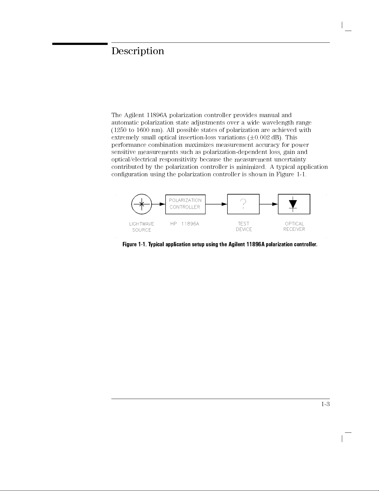
The
Agilent 11896A
automatic
(1250
extremely
performance
sensitive
optical/electrical
contributed
conguration
polarization state
to 1600
nm). All
small optical
combination maximizes
measurements
responsitivity
by
the
using the
polarization
controller
adjustments
possible
states
insertion-loss variations
such
as
polarization-dependent
because
polarization
polarization
controller
controller
provides
over
of
polarization
a
wide
(
6
0.002
manual
wavelength
are
achieved
dB).
measurement accuracy
loss
the
measurement
is
minimized.
is
shown
uncertainty
A
in
and
This
for
,
gain
typical
Figure
range
with
power
and
application
1-1
.
Figure
1-1.
T
ypical
application
setup
using
the
Agilent
11896A
polarization
controller
.
1-3
Page 20
General
Information
Description
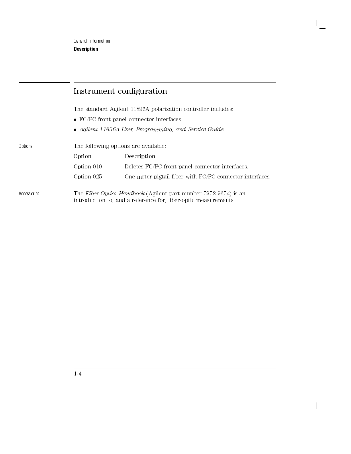
Instrument conguration
Options
Accessories
The standard
FC/PC
A
The
front-panel connector
gilent
11896A
following
Option
Option
Option
The
010
025
Fiber
Optics
introduction
Agilent 11896A
User
,
Programming,
options are
Description
Deletes
One
meter
Handbook
to
,
and
a
reference
polarization
interfaces
available:
FC/PC
front-panel
pigtail
(Agilent part
for
,
controller
and
Service
connector
ber
with
FC/PC
number 5952-9654)
ber-optic
measurements
includes:
Guide
interfaces
connector
is
an
.
.
interfaces
.
1-4
Page 21
General
Information
Description
P
ower
meter
measurement
PDL
system
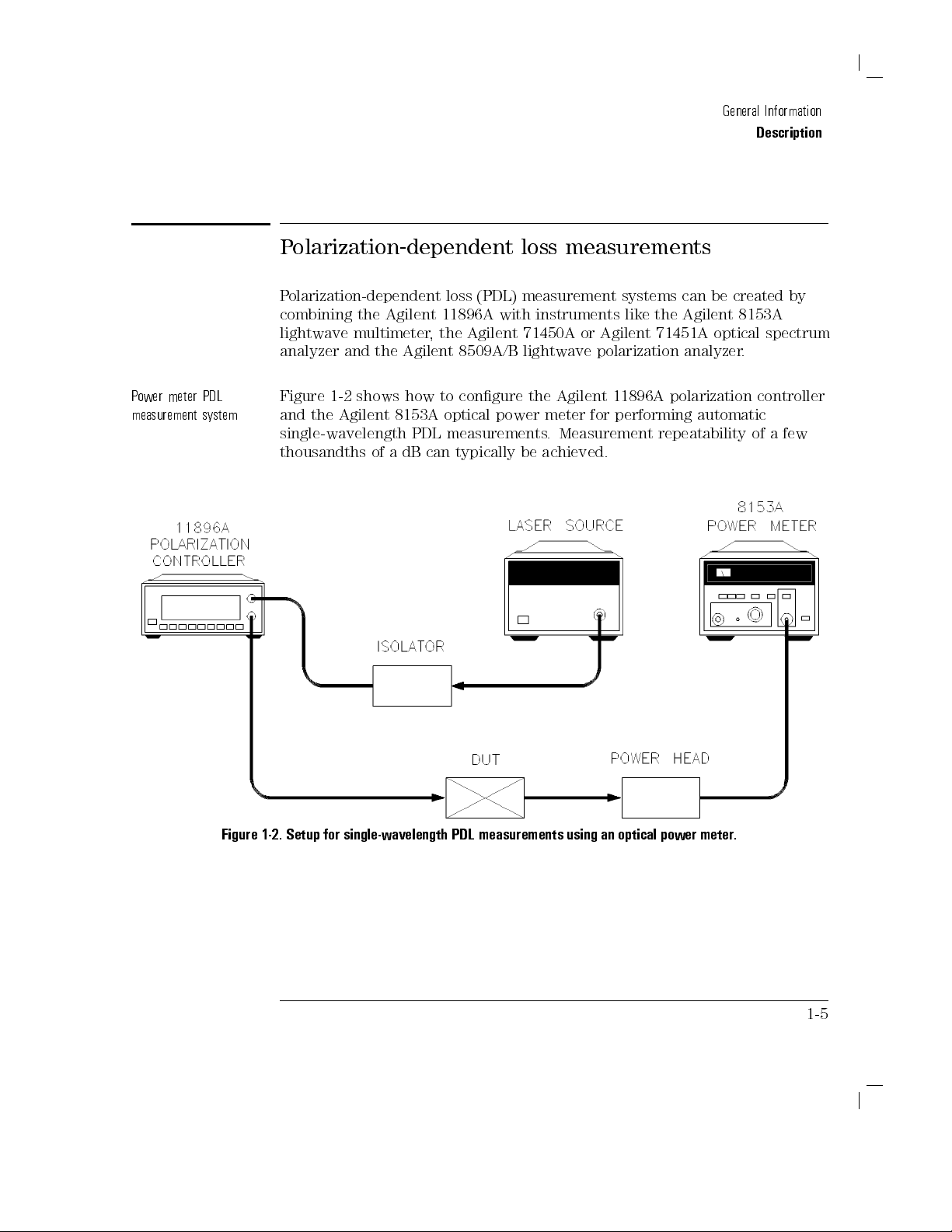
Polarization-dependent
Polarization-dependent
combining the
Agilent 11896A
lightwave multimeter
analyzer and
Figure
and
the Agilent
the
1-2 shows
8153A optical
single-wavelength
thousandths
of
a
, the
Agilent
how to
PDL
dB
can
loss (PDL)
with instruments
Agilent 71450A
8509A/B
congure the
power
measurements
typically
loss measurements
measurement
lightwave
Agilent
meter
.
Measurement
be
achieved.
systems
like
or
Agilent
polarization
11896A
for
performing
can
the
Agilent
71451A
analyzer
polarization
automatic
repeatability
be
created
8153A
optical
.
by
spectrum
controller
of
a few
Figure
1-2.
Setup
for
single-wavelength PDL
measurements
using
an
optical
power
meter
.
1-5
Page 22

General
Information
Description
Swept-wavelength
measurement
Figure
system
SWPTW
Figure
PDL
Figure
and
the Agilent
swept-wavelength
A
VE
here
.
1-3.
Setup
for
1-3 shows
how to
71451A optical
PDL measurements
swept-wavelength
congure the
PDL
measurements
Agilent
11896A
spectrum analyzer
.
using
an
optical
polarization
for
performing
spectrum
analyzer
controller
automatic
.
1-6
Page 23
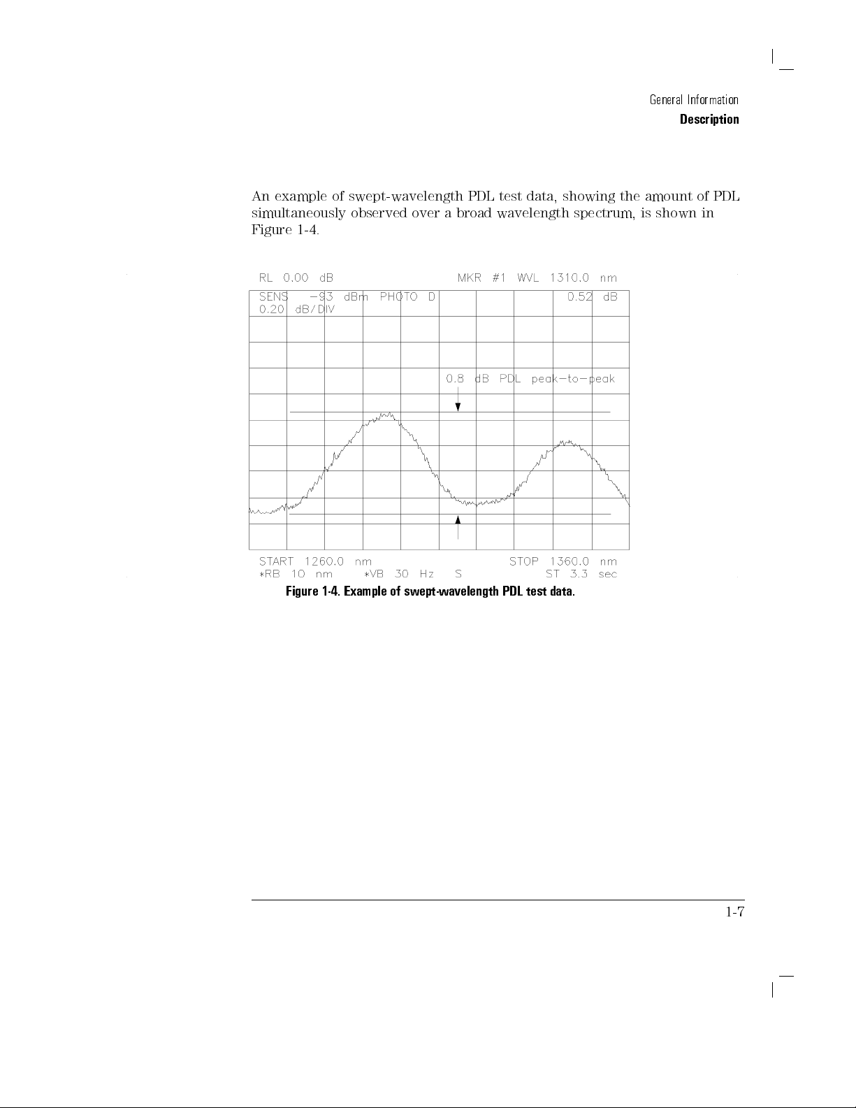
An
example
of
simultaneously
Figure
1-4
.
swept-wavelength
observed
over
a
PDL
broad
test
data,
wavelength
showing
spectrum,
the
General
amount
is
shown
Information
Description
of
PDL
in
Figure
1-4.
Example
of
swept-wavelength
PDL
test
data.
1-7
Page 24
General
Information
Description
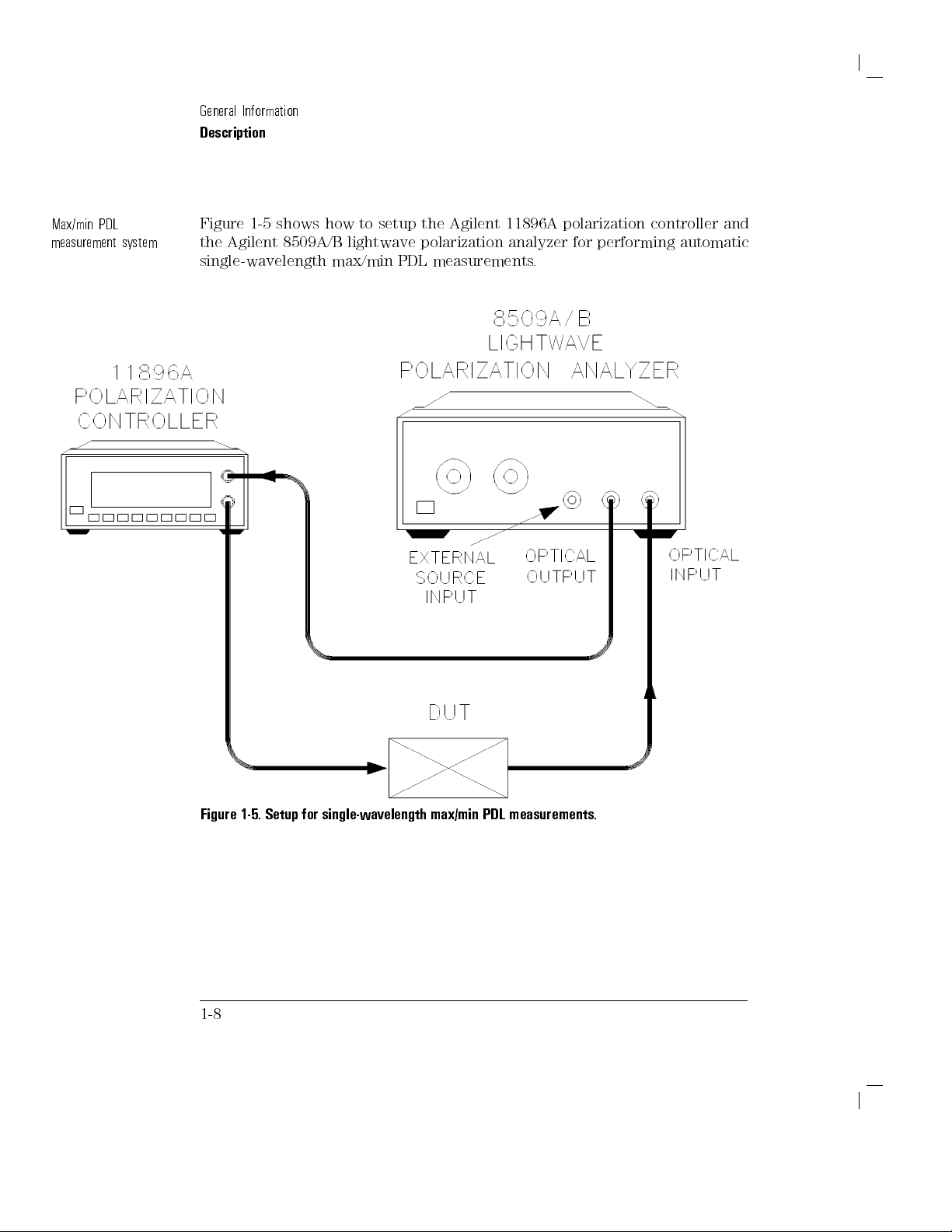
Max/min
PDL
measurement
system
Figure
the
1-5 shows
Agilent 8509A/B
single-wavelength
how to
setup the
lightwave polarization
max/min PDL
measurements.
Agilent
11896A
polarization
analyzer for
controller
performing
and
automatic
Figure 1-5.
1-8
Setup for
single-wavelength
max/min
PDL
measurements.
Page 25

An
example
states
on
the
values
of
of
polarization
P
oincare
actually
max/min
are
sphere
occur
during
PDL
measurement
displayed
at
the
the
as
Stokes
points
where
measurement.
data
is
shown
parameters
maximum
and
and
General
in
Figure
PDL
minimum
Information
Description
1-6
.
The
markers
power
Figure
1-6.
Example
of
max/min
PDL
measurement data.
1-9
Page 26

Theory
of
Figure
The
transmitted signal
the
internal four-ber-loop
optimized
polarization
polarization
over
(000{999),
made
GPIB
RECALL
to
approximate
controller's
adjustability
an
angular
providing
manually
commands
registers
range
,
using
or
Operation
1-7.
Agilent
11896A polarization
enters the
assembly.
a quarter-wave
specied
is
achieved
.
This
180
front-panel
autoscanning
the
of
an
the
built-in
adjustment
.
controller block
polarization
The
controller
dimensions
retarder
wavelength range
by independently
range
is
divided
resolution
knobs
of
0.18
,
or
automatically
control
and
of
each
response
.
Complete
adjusting
into
.
A
and
the
diagram.
passes
loop
over
the
and
each
1000
equal
djustments
,
using
S
A
VE
through
are
continuous
loop
steps
can
be
remote
and
1-10
Page 27

Specications
This
section contains
Agilent
apply
All
after
Fiber
11896A polarization
over the
temperature range
specications apply
1 hour
continuous operation
pigtail
interfaces
stated.
and
Characteristics
specications
controller
after the
are
instrument's
assumed
and
characteristics
.
The
C
to +55
0
and
self-calibration
for
all
specications
C
(unless otherwise
temperature
cases
,
except
for
the
in
has
routines
where
this
chapter
been
have
otherwise
noted).
stabilized
been
run.
Specications
Characteristics
Calibration
cycle
Specications
Characteristics
functions
italics
Agilent
and performance
.
Technologies
recommended
periodic
Agilent
T
echnologies
recalibrations
11896A
describe
provide
calibration
polarization
service
warranted performance
useful,
warrants
are
facility
but
of
the
instrument
interval.
necessary
controller
every
nonwarranted,
instrument.
T
o
maintain
.
W
e
be
24
months
.
information
Characteristics
specications
specications
recommend
calibrated
.
at
that
an
over
the
Agilent
are
the
,
about
printed
the
in
1-11
Page 28
General
Information
Specications and
Characteristics
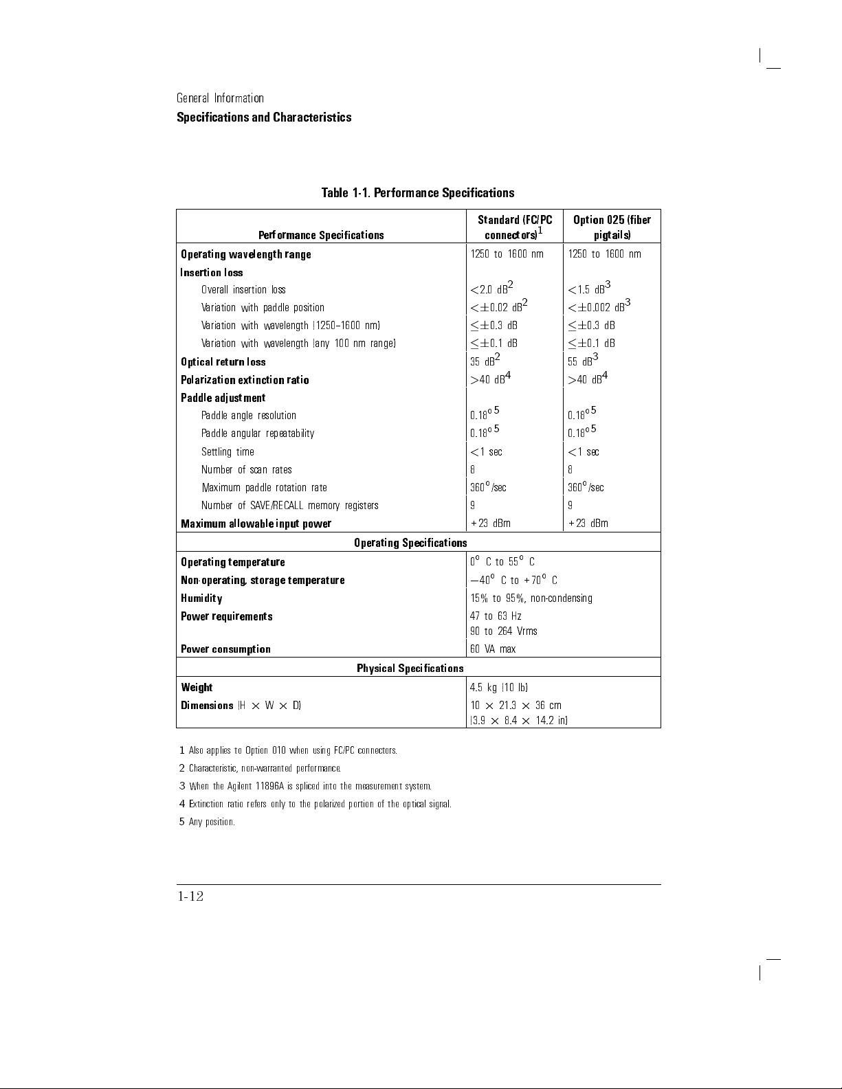
T
able
1-1.
P
erformance
Specications
Operating
Insertion
Overall
wavelength
loss
insertion
Variation
V
ariation
V
ariation
Optical
return
P
olarization
Paddle
adjustment
P
addle
angle
P
addle angular
Settling
time
Number
Maximum
Number
Maximum
Operating
allowable
temperature
Non-operating,
Humidity
P
ower
requirements
P
ower
consumption
Weight
Dimensions
P
erformance
loss
with paddle
with
wavelength
with
wavelength
loss
extinction
resolution
repeatability
of
scan
rates
paddle
of
SA
VE/RECALL
storage
(H
2
W
range
position
ratio
rotation
memory
input
power
temperature
2
D)
Specications
(1250{1600
(an
y
100
nm
rate
registers
Operating
Physical
nm)
range)
Specications
Specications
Standard
connectors)
1250
to
<
2.0
<
6
0.02 dB
6
0.3
6
0.1
2
35
dB
>
40
dB
5
0.18
5
0.18
<
1
sec
1600 nm
2
dB
dB
dB
4
(FC/PC
2
Option
1
1250
to
<
1.5
<
6
0.002 dB
6
0.3
6
0.1
55
dB
>
40
dB
5
0.18
5
0.18
<
1
sec
8 8
360/sec 360/sec
9 9
+23
0C
0
15%
47
90
60
4.5
10
(3.9
40
to
to 264
V
A
kg
2
2
dBm
to
55
C
to
to 95%,
63
Hz
max
(10
21.3
8.4
+70
Vrms
lb)
2
2
+23
C
C
non-condensing
36
cm
14.2
in)
dBm
025
pigtails)
1600 nm
3
dB
dB
dB
3
4
(ber
3
1
Also applies to Option 010 when using FC/PC connectors.
2
Characteristic, non-warranted
3
When the Agilent 11896A is spliced into the measurement system.
4
Extinction ratio refers only to the polarized portion
5
Any position.
performance.
of the optical signal.
1-12
Page 29
Specications and
General
Information
Characteristics
1-13
Page 30

Serial
Numbers
Agilent
their
T
echnologies service
changes
Whenever
have
complete
to
the
parts:
ve
Technologies
performance,
to each
you contact
the
complete
and
accurate
the
rear
of
the
options installed
the
prex
numbers).
Whenever
type of
obtain information
including the
full prex
makes
usability
personnel have
equipment,
Agilent T
serial
number
information
polarization
in
the
(the
rst
four
you
about your
and
frequent
,
or
reliability
based
echnologies
available
possible
controller
polarization
numbers
refer
to
controller,
sux.
improvements
,
and
to
access
on
to
the
complete
about
to
ensure
.
A
serial-number
.
It
contains
controller
and
a
letter),
the serial
be
number when
sure
to
its
products
control
costs
records
equipment's
your
polarization
obtaining
the
serial
.
The
serial
and
the
to
use
the
to
.
Agilent
of
design
serial
the
most
label
is
number
number
sux
using it
complete
enhance
number
controller
attached
and
has
two
(the
last
to
number
.
,
,
1-14
Page 31

Electrostatic
Discharge
Information
Electrostatic
All
work on
station.
types
of ESD
Conductive table-mat
Conductive
Both
types
Of
the two
ESD
protection
accessories must
W
A
N
I
N
G
These techniques
working
discharge (ESD)
electronic
Figure 1-8
protection:
oor-mat
,
when
,
only
the
when
provide at
on
circuitry with
assemblies
shows an
and wrist-strap
and
used
together
table-mat
used
for a
static-safe
can
damage
should
example
heel-strap
,
provide
and
alone
.
least
1
a
voltage
or
be
of
a
combination.
combination.
a
wrist-strap
To
ensure user
M
of
isolation
work
station
potential
destroy
performed
static-safe
signicant
combination
safety,
from
should
greater
electronic
at
a
static-safe
work
station
level
of
provides
the
ground.
not
than
components
using
ESD
protection.
static-safe
be
used
500
volts
.
work
two
adequate
when
.
1-15
Page 32

General
Information
Electrostatic Discharge
Information
1-16
Figure
1-8.
Example
of
a
static-safe
work
station.
Page 33

General
Information
Reducing ESD
The following
testing and
Before
time each
suggestions may
servicing operations
connecting any
day
damage
coaxial cable
,
momentarily
help
.
ground
reduce
to
the
cable.
P
ersonnel
touching
assembly
Be
sure that
buildup of
T
able
1-2 lists
T
echnologies
Agilent
should
the
from
be
center
the
all instruments
static charge
static-safe accessories
using the
Part
grounded
pin
of
any
unit.
.
Agilent part
T
able
with
connector
are
1-2.
Static-Safe
a
resistor-isolated
properly
that
numbers
Number Description
9300-0797 Set
9300-0980 Wrist-strap
wire
includes:
.
(The
3M
static
wrist-strap
cord
1.5
m
control
and
(5
mat
wrist-strap
ft).
0.6
cord
ESD
damage
an
instrument
center
and
and
before
earth-grounded
can
be
obtained
shown.
Accessories
m
2
1.2
m
(2
are not
included. The
outer
removing
ft
2
4
that
occurs
connector
conductors
wrist
strap
to
prevent
from
Agilent
ft)
and
4.6
y
must
be
for
any
cm
(15
ordered
during
the
of
before
a
ft)
ground
separately
rst
the
.)
9300-1383 Wrist-strap
post-type
9300-1169 ESD
heel-strap
,
color
black,
connection.
(reusable
stainless
6
to
12
steel,
months).
without
cord,
has
four
adjustable
links
and
a
7
mm
1-17
Page 34

General
Information
Page 35

2
Installation
Preparation for Use
and
Page 36

Installation
What
Preparing
T
Making
you'll nd
urning
the
polarization
on
the controller
ber
optic
in this
connections.
and Preparation
chapter
controller for
.
use.
for Use
2-2
Page 37

Preparing
the
P
olarization Controller
for Use
Initial
Inspect
container
that
mechanically
polarization
Notify
the
the
Check"
the
of
K
eep
T
echnologies
a
claim
them
to
another
\How
P
ower cable
inspection
the
Agilent
or
the
contents
controller
the
carrier
contents
verication
in
shipping
stress
.
the
shipping
settlement.
for
possible
location
to
Return
cushioning
Chapter
11896A shipping
are
and
electrically
if:
are
incomplete
test
5).
container
materials
oce
will
If
future
or
the
Agilent
Table
2-1. Accessories
material
complete
.
(this
is
arrange
the
shipping
use
return
Description Agilent
is
damaged, keep
and
you
.
T
able
or
if
the
procedure
damaged
for
the
for
repair
materials
.
Y
ou
may wish
it
to Agilent
11896A
Supplied with
See
container for
have
tested
2-1
lists
the
polarization
is
provided
or
the
cushioning
carrier's
inspection.
or
replacement without
are
to ship
Technologies
for
Service
Part
Number
Table
2-3
damage.
it until
the
accessories
controller
in
\P
in good
the
"in
Chapter 5.
the Agilent
Shipped
If the
shipping
you
have
polarization
shipped
does
not
erforming
material
The
a
shows
Agilent
V
waiting for
condition, retain
polarization
for service
. Refer
11896A
Comments
with the
polarization
veried
erication
controller
controller.
Operating and service manual 11896-90001 Shipped with the polarization
controller.
controller
with
the
pass
signs
to
2-3
Page 38

Installation
and
Preparing the
Preparation
Polarization
for
Use
Controller
for
Use
CA
Connecting the
The polarization
installation other
U
T
I
O
N
Do not
correct and
connect ac
the
proper
Agilent 11896A
controller is
a
than connection
power until
fuse
you
is
installed.
portable
to
a
have
to
instrument
power
source
veried
Damage
a
that
to
and
the
power
requires
.
the
line
equipment
source
no
physical
voltage
could
is
result.
P
ower
requirements
T
able
2-2.
Agilent
11896A
P
ower
Requirements
Characteristic Requirement
Input
Frequenc
P
ower
V
oltage
y
90
47
60
to
264 Vrms
to
63
VA
(maximum)
Hz
Checking the
The recommended
The
line
fuse is
Figure 2-1). The spare fuse is stored below the line fuse
fuse
fuse is
housed
in
a
a
2
A,
small
250
V
,
container
Agilent
in
part
the
number
line
2110-0710.
module
.T
(refer
o check the fuse
insert the tip of a screwdriver between the instrument and the side of
the
container. Gently pull outward to remove the container
defective or missing, install a new fuse in the proper position
fuse container
.
. If the fuse is
and reinsert the
2-4
to
,
Page 39

Preparing the
Installation
Polarization
and
Preparation
Controller
for
for
Use
Use
Figure
2-1.
Power
cable
The polarization
accordance with
controller is
equipped with
international safety
Checking
the
a
standards.
fuse.
three-wire
power
When connected
cable
to an
,
in
appropriate power line outlet, this cable grounds the instrument cabinet.
2-5
Page 40

Installation
Preparing the
F
W
A
R
N
I
NG
ailure
personal
connect
the
socket
earth-grounding
autotransformer
an
protective
V
arious
the
appropriate
shipped
for
illustrates
each
and
Preparation
Polarization
to
ground
injury
.
Before
its
protective
main
power
outlet
cable
that
protection
without
autotransformer
earth
contact
types
use
cable
power
in
of
ac
for
is
included
dierent
the
is
appropriate
cables
power
the
plug
for
Use
Controller
the
polarization controller
earth
.
has
a
,
make sure
are
outlets
area
with
areas
congurations
for
turning
terminals
Insert
the
protective
by
a
protective
of the
available
unique
to
which
the
unit.
.
T
able
Use
on
main power
using
its common
power source
to
the
Y
2-3
,
and
.
properly can
the
polarization controller
to
the
protective conductor
cable plug
earth
contact. DO
an
extension
ground
cable
conductor
terminal is
outlet socket.
connect
to
polarization
ou
can
lists the
identies
the
polarization
specic
geographic
controller
order additional
available ac
the
result in
only into
NOT defeat
,power
.
If you
connected to
areas
is
ac power
power cables
geographic
,you
must
of
a
the
cable,
are using
controller
.
The
originally
cables
,
area in
or
the
to
cable
which
2-6
Page 41

T
able
2-3.
AC
P
ower
Preparing the
Cables
A
vailable
Installation
Polarization
and
Preparation
Controller
for
for
Use
Use
2-7
Page 42

Turning
With
the
power
controller
moment,
refer
on by
numerals appear
to
\P
erforming
on
cable
rocking
the
Agilent 11896A
inserted
a
V
erication
the
front-panel
on the
into
the
front-panel
Check"
line
switch
in
module
to
LCD
Chapter
the
.
,
If
turn
\1"
the
5.
the
polarization
position.
LCD
fails
After
to
a
light,
2-8
Page 43

Lightwave
Introduction
Connector
Care
Lightwave
connection
nonrepeatable
best
Lightwave
connections
sources
or
components
Fiber
and
combinations
of
cables
cable
practices
,
receivers
optic
in
dierent
do
interfaces
procedures
or
inaccurate
to
clean,
connectors
may
be
used
,
patch
.
cables
are
environments
,
jackets
not
work
.
,
well
Dirty
care
are
used
and
can be
for
used
to
join
panels
at
indexes
together
damaged by
or
damaged lightwave
measurements
,
connect,
to
cables
,
terminals
dierent
.
There
.
connect
between
wavelengths
are
of
refraction.
Cables
and
a
improper cleaning
interfaces can
.
This
section
inspect
two
ber
lightwave
ends
optical
and
many
other
,
in
variety
should
of
In
general,
match
sizes
will
suggest
together
ports
on
types
single
or
,
core/cladding
dierent
each
other
and
result
some
connectors
.
These
devices
of
,
systems
multi-mode
types
and
in
.
laser
the
system.
However
to
to
repeatability
Lightwave connectors
connectors.
small ber
less in
microns
,
provide
another
diameter,
in
regardless
a
direct
.
When
becomes
In a
ber optic
core.
Because ber
and dust
diameter
of
and
these
,
dust
an
the
cable
type
low-loss
optical
connectors
important
dier from
system, light
cores are
particles range
and
very
,
the connectors
signal
transition from
are used
factor
in a
.
electrical or
is
transmitted
often
from tenths
minute
contamination
have only
one ber
measurement system,
microwave
system
through
62.5
microns
of a
(0.0625
micron
on
the end
one
function:
an
extremely
mm)
to
several
of
end
or
the
ber core can degrade the performance of the connector interface (where the
two cores meet). Therefore
connector
interface free of trapped foreign material.
, the connector must be precisely aligned and the
,
Connector (or
of a lightwave
insertion) loss is one important performance characteristic
connector.
Typical values are less than 1 dB of loss
,and
sometimes as little as 0.1 dB of loss with high performance connectors
.
2-9
Page 44

Installation
and
Preparation
Lightwave Connector
Care
for
Use
Return
loss
reection
The
best
40
dB
,
although
Causes
of
dierences
reections
use
and
removal
A
chieving
(no
air
gap)
1.
the
type
2.
using
lossy
or
is
not
be
less
dierence
is
another
the
better
physically
20
connector
in
the
caused
the
best
and
properly
of
connector
the
proper
reective
smooth
accurate
in
optical
important
(the
contacting
to
30
loss
numerical
by
damaged,
of
index
possible
.
cleaning
,
light
or
the
connection
.
F
or this
measurement
factor
larger
the
return
connectors
dB
is
more
common.
and
reections
aperture
worn,
matching
compounds
connection,
aligned,
will
and
connecting
not
depends
make
is
reason, lightwave
.
It
is
loss
have
include
of
two
or
loose
where
on
a
smooth
not
repeatable
systems
a
measure
,
the
smaller
return
core
bers
,
spacing
ber
ends
.
the
ber
two
things:
techniques
transition.
,
connections
.
of
reection:
the
reection).
losses
better
misalignment,
and
air
,
and
the
end
faces
.
If
the
connection
If the
measurement
can
make
the
less
than
gaps,
improper
are
ush
transition
data will
a
critical
is
2-10
Page 45

Installation
and
Lightwave Connector
Preparation
for
Use
Care
Denition
Handling
Cleaning
Cleaning and
Proper cleaning
achieving accurate
Technologies
before each
measurement
Information on
to properly
of
terms
T
o
avoid
mate
confusion,
Connector
A
dapter
Always
ends
or
Always
they
Three
handle
should
cleaning
keep
are
not
cleaning
never
solutions
in
clean non-lensed
clean lightwave
lightwave connections
handling
and handling
of
lightwave
and repeatable
lightwave equipment.
using
the
protecting
connectors
and
storing
are
also
the following
Houses
cable
Does
connectors
lightwave
connectors
use
processes
lightwave
adapters
be
.
and
(See
the
or
on
not
contain
.
connectors
allowed
tools
and
\Storage
are
.
The
ber
the
front
to
touch
.
cable
provided.
connectors
third
.
connectors
measurements with
Lightwave interfaces
techniques
your
included
denitions
end,
most
panel
optical
and
anything
ends
covered
described
connectors/cables
in
this
are
used
open
at
of
an
instrument
ber
.
Used
cable
ends
except
with
.")
The
rst
process
.
The
second
process
describes
is
imperative
your
should
in
section.
in
this
the
end
to
mate two
with
other
a
protective
describes
process
how
Agilent
be
cleaned
this
handbook.
and
tips
handbook.
of
a
lightwave
or
accessory.
optical
great
care
.
mating surfaces
cap
how
describes
to
care
for
for
Fiber
how
on
how
when
to
lensed
to
CA
UT
I
O
N
Agilent
NOT
as
you
manufacturer for information on application and cleaning procedures
be
gels
think
T
echnologies
applied
,
may
be
the
to
dicult
use
of
strongly
their
such
recommends
Instruments
to
remove
compounds
and
and
that
accessories
can
contain
is
necessary
index
matching
.
Some
compounds
compounds
damaging particulates
,
refer
to the
compound
,
such
.If
.
2-11
Page 46

Installation
and
Preparation
Lightwave Connector
Care
for
Use
Equipment
C
A
U
T
Process
Cleaning non-lensed
The
following
lightwave
Any
commercially
Cotton
Compressed
I
O
N
Agilent
to
clean
that
can
Before
cleaning
connector
air
.
Then
scrubbing
alcohol
to
times
a
cotton
.
alone
This
is
connectors
swabs
air
T
echnologies
optical
ber
degrade
the
.
Use
isopropyl
use
alcohol
of
the
will
swab
technique
a
list
of
.
available
:
:
:
:
:
:
:
:
:
:
:
:
recommends
ends
performance
ber
to
ber
end
not
remove
and
moving
can
lightwave connectors
the
items
that
should
denatured
:
:
:
:
:
:
::
::
::
::
:
:
:
:
:
:
:
::
::
::
::
:
:
:
:
:
that
you
.
F
oam
swabs
can
alcohol
:
:
:
:
:
:
:
:
:
:
do
leave
be
:
Agilent
:
Agilent
not
.
end,
clean
the
ferrules
alcohol,
clean
can
help
the
help
them.
it
back
remove
clean
ber
remove
This
and
cotton
end.
swabs
Some
particles
can
be
forth
across
or
displace particles
used
use
lmy
and
amount
done
to
part
part
any
deposits
other
,
and
when
by
the
clean
non-lensed
number
number
type
of
on
parts
of
clean
compressed
of wiping
application
applying
ber
end
smaller
8520-0023
8500-5262
foam
swab
ber
ends
the
or mild
of
the
alcohol
several
than
one
micron.
Allow
the
compressed
the
ber
end
across the
soon as
the connector
connector
air
after
ber end.
to
.
Compressed
the
alcohol
Visually inspect
is dry
dry
(about
air
lessens
evaporates.
,
the
connection
a
minute)
the
the
chance
It should
ber
or dry
end
should
it immediately
of deposits
be blown
for
stray
be
made
horizontally
cotton
.
with
clean
remaining on
bers
.
As
CA
UT
IO
N
Inverting the
the sprayed
compressed air
surface.
Refer to
canister while
spraying will
instructions provided
on
produce
the
compressed
residue
air
on
canister.
2-12
Page 47

Installation
and
Lightwave Connector
Preparation
for
Use
Care
Equipment
Process
Cleaning lightwave
All
of
the
items
listed
above
lightwave
with
connector
N
As
are
outweighs
Clean
with
clean
adapters
isopropyl
adapters
O
T
E
noted
in
a
very
thin
the
the
adapter
a
foam
compressed
alcohol
previous
however
risk
of
swab
.
In
addition,
and
.
caution
statement,
,
and
the
risk
contamination
by
applying isopropyl
.
Allow
air
.
adapters
for
cleaning
small
compressed
the
of
other
of
foam
the
adapter
connectors
foam
air
foam
swabs
contamination
swab
deposits
alcohol
to
air
swabs
to
clean
can
buildup
left
dry
,
leave
from
to
or
may
may
the
lm
on
the inside
cleaning
the
dry
be
used
be
used
inside
of
y deposits.
of adapters
the
inside of
inside
of
it
immediately
to
clean
along
lightwave
These deposits
greatly
adapters.
the
connector
with
Cleaning
Some
instruments may
connection
is
received into a lens rather than into a connecting ber
lensed
does
not
connections
have a
provide a
connector
physically
that
is
\lensed."
contacting
In
other
connection,
. These receiving
but
words
the
,
the
light
lenses usually have an anti-reective coating that is very easily damaged.
Therefore, these connectors should NEVER have cleaning solutions or any
other substance applied to them unless it is specically recommended by the
manufacturer.Y
from time to time
ou may wish to use clean compressed air to rid
.
them of dust
2-13
Page 48

Installation
and
Preparation
Lightwave Connector
Storage
All of
Agilent T
laser shutter
echnologies'
caps or
instrument. Also
cable ends
covers should
from
be
for
Care
dust caps
,all
of the
damage
kept
Use
lightwave
cables
or
contamination.
on
the
equipment
on
instruments
the
lightwave
that
are
shipped
These
at
all
are
adapters
dust
times
shipped
have
caps
except
that
covers
and
when
with
either
come
with
to
protect
protective
in
use
the
the
.
The adapters
the
connectors
keep
the
exposed connector
Protective
covers
instruments,
dust covers
The
list
below provides
and
dust
caps that
that
so it
on.
Laser
FC/PC
Biconic
DIN
HMS
ST
dust
SC
dust
were
shipped
on
the
instrument.
for
these
exposed
is best
to
the Agilent
are provided
Item Agilent
shutter
cap
dust cap
dust
cap
dust
cap
10
dust
cap
cap
cap
of
keep
on
your
the
with
your
instrument
If
you
remove
instrument
connectors
adapters
part
numbers
lightwave
Part
these
covered
are
on
the
instruments
No.
08145-64521 All
08154-44102 opt
08154-44105 opt
5040-9364 opt
5040-9361 opt
5040-9366 opt
1401-0253 opt
can
not
provided
instrument
for
the
Connector
be
removed
adapters
until
the
laser
and
Option
options
012
015
013
011
014
017
from
you
should
next
with
with
shutter
accessories
use
the
the
cap
.
.
2-14
Page 49

Making connections
Installation
and
Lightwave Connector
Preparation
for
Use
Care
Proper connection
insertion technique
connector type
Attempting to
connection from
surfaces.
enough because
but
have
angled-contact
manufacturer's
in order
connect incompatible
functioning
A
visual
some
dierent
or
data
connecting.
When you
ber
this
Many
repeatability
ferrule
straight,
Most
pounds
result
tighten
data
insert the
end
does not
way
, you
connectors
is
properly
rotate
connectors
of
force
in
misalignment
the
connector
sheet
for
will not
that
it
using
.
Over-tightening
any
technique requires
and torque
to ensure
requirements
mechanical
properly
inspection
connector
optical
ber
of
the
types
interfaces
mechanical
straight-contact ber
sheet
to
conrm
ferrule into
touch the
rub
have
a
also
helps
seated
to
align
springs
the
keyed
inside
the
a connector
outside
ber
slot
to
align
the
key
,
to
push
end
provided
and
or
and
nonrepeatable
in
a
consistent
torque
recommendations
attention
to
connector
.
Connectors
and
optical
connector types
and
even
cause
interfaces
have
the
same
(for
example
interfaces).
connector
of
the
against
and
seat
other
tighten
ber
type
or
adapter
mating
any
for
optimum
the
two
connector
it
with
ends
together
connector
under-tightening
measurements
manner
.
Refer
.
compatibility
must
be
compatibility
may
prevent
damage
may
to
not
mechanical
,
angled-no-contact,
Refer
to
the
compatibility
,
make
sure
or
adapter
undesirable
surface
measurement
connectors
,
use
one
hand
the
other
hand.
exert
one
these
connectors
.
Always
to
the
manufacturer's
the
.
the
the
ber
be
interface
before
that
.
After
to
keep
to
nger
,
same
the
.
In
.
the
two
can
it
2-15
Page 50

Installation
and
Preparation
Lightwave Connector
Summary
Care
for
Use
Visual
inspection
When making
the following
measurements:
Conrm
Use
Be
Use
K
eep connectors
extreme
sure
the
the
cleaning
connector
Inspection
Although
it
is
Contamination
well
as
cracks
Several
an
some
ber
inspection
enlargement
method
measurements with
precautions will
type
care
in
handling
connector
methods
and cable
not
necessary
and/or
or
imperfections
chips
in
help to
compatibility
interfaces
described
ends
,
visual
the
ber
scopes
range
of
100
2
to hold
the ber
in place
lightwave
all
are
covered
itself.
are
on
to
200
insure
.
lightwave
clean
in
this
when
inspection
on
the
the
market,
2
can
while
instruments
good,
reliable
cables
before
and
making
handbook.
not
of
ber
cable
endface
but any
be used.
viewing
or
accessories
,
repeatable
connectors
any
in
use
.
ends
can
can
microscope with
It is
helpful to
in
this
range
.
connections
be
helpful.
be
detected
devise
.
,
.
as
Inspect
metal,
and chips
Visible
performance of the lightwave
the bers from contacting).
the
entire endface
as
well as
any other
.
imperfections
for contamination,
imperfections.
not
touching
connection (unless the imperfections keep
Consistent optical measurements are the best
the ber
assurance that your lightwave connection
2-16
raised metal,
Inspect the
core
may
ber
not
or dents
core
aect
is performing properly
for
the
.
in
the
cracks
Page 51

Installation
and
Lightwave Connector
Preparation
for
Use
Care
Introduction
Insertion
loss
Optical performance
Consistent
indication
the
insertion
you
test
receipt,
in
the
Insertion
congurations
an
the
an
an
measurements
that
you
loss
your
cables
and
retain
future
loss
if
any
can
.
Some of
Agilent 8702
lightwave
Agilent
Agilent
83420
8153
have
and/or
and
the
measured
degradation
be
tested
or Agilent
source
lightwave
lightwave
with
good
return
accessories
these are:
and
modules
Many
other
lightwave
provided
perform
As
mentioned
than
1
dB
particular
possibilities
source
with
your
an
insertion
earlier
,
and
cable
and
can
or
exist.
a
compatible
lightwave
loss
test.
in
this
be
as
little
accessory
testing
your
lightwave
connections
loss
of
your
for
data
for
has
occurred.
using
a
number
8703 lightwave
receivers
test
set
with
multimeter
The
basic
lightwave
test
equipment
handbook,
as
0.1
dB
,
refer
to
the manufacturer
equipment
.
However
,
lightwave
insertion
loss
comparison,
of
dierent
component analyzer
an
Agilent
with
source
requirements
receiver
for
information
typical
.
insertion
F
or
actual specications
you
cables
and
you
8510
and
are
.
Refer
.
are
may
return
will
test
equipment
network
power
an
loss
a
good
wish
to
or
accessories
loss
upon
be
able to
system
analyzer
sensor
appropriate
to
the
manuals
on
how
to
for
cables
on your
know
tell
with
is
less
.
If
,
2-17
Page 52

Return
loss
Installation
Return
and
loss can
congurations
an Agilent
an Agilent
lightwave
an Agilent
an Agilent
module
Many
other
possibilities
lightwave
lightwave
Refer
to
source,
coupler
the
information
Preparation
for
be tested
.Some
of these
8703 lightwave
8702 analyzer
coupler
8504 precision
8153 lightwave
exist.
a
compatible
.
manuals
on
how
provided
to
perform
Use
using a
number of
are:
component analyzer
with the
appropriate
reectometer
multimeter
The
with
basic
lightwave
with
your lightwave
a
return loss
dierent
source
an
Agilent
requirements
receiver
,
and
test equipment
test.
test
equipment
,
receiver
81543
are
an
a
compatible
and
return
loss
appropriate
for
As mentioned
to 30
dB,
and
particular
cable
earlier in
can
be
better
or accessory
this
than
,
handbook,
40
dB
refer
to
typical
.
F
or
actual
the
manufacturer
return
loss
specications
.
is
better
on
than
your
20
2-18
Page 53

3
Using
the
Agilent
11896A
Polarization Controller
Page 54

Using
the Agilent
11896A
Polarization
What
Agilent
Agilent
Instructions
you'll nd
11896A
11896A
for
in this
series
series
manually
Controller
chapter
front-panel features.
rear-panel features.
operating
the
polarization controller
.
3-2
Page 55

Front-P
The
front panel
Polarization
Instrument state
Data entry
anel
of
the
adjustment
F
eatures
polarization
controller
includes
three
main
sections:
3-3
Page 56

Using
the
Agilent
Polarization
Front-Panel
The
front
The
right-most
RECALL
function
11896A
Controller
Features
panel
register
keys
.
includes
knob
is
numbers
a
also
display
used
,
and
the
and
to
four
adjust
GPIB
knobs
the
scan
address
for
rate
when
adjusting
,
the
S
using
the
AVE
and
the
front-panel
paddles
.
1
2
3
4
5
3-4
The
Agilent
Display
instrument
Status
LSN,
P
olarization
4
A
UTO
screen.
settings
indicators
TLK,
and
5
,
SCAN
adjustment keys
and
Instrument state
4
5
LOCAL
Data entry
keys.
keys.
11896A
Used
to
.
.
Indicates
SRC
lines
4
SCAN
keys.
Includes the
front
panel.
display
the current
.
.
5
keys
RA
TE
Includes
paddle
Includes
.
the
4
4
CANCEL
positions
status of
the
5
SA
VE
5
and
4
MANUAL
,
4
RECALL
4
ENTER
and
the
RMT
5
,
5
,and
5
keys.
,
Page 57

Error
codes
The
digit
Error
controller
7-segment
Message
has
LED
six
display:
Type
error codes
of
Error
that can
appear on
the
Using
the
Polarization
Front-Panel
front
panel
Agilent
11896A
Controller
Features
twelve
MOTOR
SCPI
The
ERROR
ERR
following
instrument
SCPI
E1
SCPI
E2
Error
HAP
E1
If
any
of
these
service
.
Refer
1
Error parking
motor
Execution problem
the
memory
is
displayed
attempt
errors
is
initially
errors
to
Chapter
can
turned
are
and
so forth.
to
reboot.
be
displayed
displayed
5
for
the motor
occurred in
or
a
CPU register
for
12
seconds
on.
on
information.
. Indicates
and
if
an
error
the
screen,
astuck
the SCPI
controller such
is corrupted.
then
the
instrument
is
detected
the
instrument
paddle
This
when
,
faulty
message
will
the
may
require
as
3-5
Page 58

Rear-P
anel
F
eatures
1
2
3-6
The
Agilent
P
ower
GPIB
11896A
input
connector
rear
panel.
Page 59

Using
the
Agilent
11896A
Precise
can
Each
three-segment
to
Nine
nine
sweeps
manually
scan
a ve-minute
manual adjustment
be made
using
paddle can
and
0
999 corresponds
save/recall
dierent
all
user-set
states
tune the
rates
are
available
, wavelength-scanning
the
rotate 180
display shows
registers
of
polarization
SOP
single-wavelength PDL
produce polarization
Remote interrogation
all
instrument
information
functions are
on
remote
of
the
front-panel
in
1000 discrete
the relative
to 180
enable
states
rapid
of
polarization
in
across
to
the
match
measurement. A
scrambling for
of all
instrument
provided
programming.
four
paddles
knobs
while
step
.
state
a
random
entire
P
oincare
the speed
PDL
measurement
utoscanning rates
some
applications
settings
via
GPIB
in
the
polarization
watching
steps of
count,
of
polarization
(SOP).
fashion,
0.18
where
A
utoscanning
eliminating
sphere
of the
application, whether
or
.
and
remote
.
Refer
to
the
display
each.
zero
hopping
.
Eight
a
three-second,
are
fast
control
Chapter
controller
.
The
corresponds
between
continuously
the
need
polarization
it
is
enough
to
of
4
for
to
3-7
Page 60

Using
the
Polarization
Using
the Agilent
Agilent
Controller
11896A
11896A
Power-up
The power
Turn the
When the
All
The
All
The
switch is
polarization controller
polarization controller
display
rmware
four
paddles
S
A
VE
contain the
T
o
use
the
To
control
Each of
Paddle
the
the
positions are
corresponds
function
located
segments
revision
are
and
RECALL
same values
Manual
paddles
four
paddles
to 180
in
are
lit
number
set
to
registers
they had
mode
from
the
can
displayed
.
the
lower
on by
is turned
for
approximately
is
displayed
the
middle
,
the
when
front
now
be
where;
left-hand
setting
on:
position
SCAN
the
panel,
controlled
\
000
corner
the
switch
one
for
approximately
(500).
RA
TE,
power
press
4
MANUAL
by
"
corresponds
of
to
second.
and
the
was
last
its
respective
5
the
.
to
the
\1"
GPIB
turned
0
front
one
,
and \
address
knob
panel.
position.
second.
o.
.
999
"
3-8
Page 61

To
continuously sweep
To
continuously and
The
scan time
has been
P
olarization
The
active 0
elapsed
current scan
T
o
set
the
randomly
clock is
minutes,
scanning
scan
time
rate
.
scan
reset
is
initiated
in
rate
all
sweep
to
00:00.
0
seconds
minutes
polarization
all
polarization
This
indicates
.
at
the
current
and
seconds
states
the
scan
rate
is
displayed,
Using
Polarization
Using
the Agilent
states
,
press
present
.
the
Agilent
along
11896A
Controller
11896A
4
A
UTOSCAN
scan
with
time
the
5
.
T
o
N
The
change
The
current
A
djust
To
select
O
TE
scan
the
the
rate
scan
scan
scan
and
returns to
rate
rate
rate
lock-in
the previous
,
press,
is
displayed.
using
the
displayed
4
SCAN
the
right-most
value if
an
RA
TE
scan
y
ke
y
5
.
rate
is
knob
,
pressed
.
press
prior
4
ENTER
to
pressing
5
.
4
ENTER
5
.
3-9
Page 62

Using
the
Polarization
Using
the Agilent
To
save an
To
save the
The
Use
T
o
save
4
ENTER
The
Agilent
11896A
Controller
11896A
instrument
number of
the
right-most
the
current
5
.
following
instrument
state
,
press
the last
knob
Save
to
select
instrument
instrument
parameters
state
4
SA
register
the
state
5
.
VE
used
desired
in
are
is
the
saved:
displayed.
register
displayed
(1{9).
register
,
press
instrument
state
(scan
or
manual)
paddle positions
scan rate
To
recall
T
o recall
The number
Use the
T
o
recall
The
instrument
paddle
scan
Recalling instrument state zero resets the polarization controller and
an
a
previously
of the
right-most knob
the
instrument
following
instrument
state
positions
rate
instrument
saved
instrument
last
Save
register
to
select
state
parameters
(scan
or
manual)
state
of
the
state
used
the
desired
displayed
are
,
press
is
displayed.
register
register
recalled:
4
RECALL
(1{9).
,
5
.
press
4
ENTER
four paddles to the middle position (500).
5
.
sets all
3-10
Page 63

To
use the
Local
function
Using
Using
the
Agilent
Polarization
the Agilent
11896A
Controller
11896A
When the
control by
T
o
display
T
o
display
The
current
Use
the
T
o
save
polarization controller
5
the
knob
.
GPIB
is
to select
pressing
or
or
change
GPIB
4
LOCAL
change
address
right-most
the
currently displayed
is
under
the
GPIB
address
,
displayed.
the desired
address,
remote
press
press
GPIB
address
5
4
LOCAL
.
address
4
ENTER
control,
(1{30).
5
.
enable
local
3-11
Page 64

Using
the
Polarization
Using
the Agilent
Agilent
Controller
11896A
11896A
Page 65

4
Programming
Page 66

Programming
What
you'll
nd
in
this
section
This
section
programming
Programmable
Y
ou
can
perform
Set
up
the
Make
measurements.
Get
data
Send
information
Other
tasks
introduces
instructions
(measurements,
are
the
basics
in
Instrumentation.
the
following
instrument.
(congurations)
accomplished
this
for
remote
manual
The
programming
basic
operations
conguration)
to
the
b
y combining
programming
conform
from
polarization
these basic
to
the
instructions
with
a
the
polarization
of
IEEE
488.2
computer
controller
functions.
a
polarization
Standard
provide
and
controller
.
the
means
a
polarization
.
controller
Digital
of
.The
Interface for
remote
controller:
control.
4-2
Page 67

Using the
Programming
Agilent 11896A
Changing the
The polarization
N
O
T
E
The
programming
HP
9000
Series
controller's default
examples
200/300
GPIB address
(factory
for
individual
Controller
commands
.
set)
primary
in
this
manual
are
written
address
in
HP
is
BASIC
20.
5.0
for
an
4-3
Page 68

T
alking
to
the Instrument
Computers
and
receiving messages
normally
statements
statements
polarization
F
or
example
sending
read
Messages
the device
appear as
commands
in using
are
address,
acting as
of a
of the
controller
,
HP
the
placed
address ensures
instrument.
The following
position
OUTPUT
The
<
to
50.
<
device
device
programmed.
the
following
pages
controllers
over
ASCII character
\host" language
host language
.
9000
Series
and
queries
ENTER
on
the
statement.
program message
that the
HP B
ASIC
program
statement
address
address
Each
of
>
the
represents
other
.
communicate
a
remote
200/300
.
bus
>
;":PADD1:POSITION
interface
strings
available
are
used
B
After
a
using an
,
and
message
sends
the
parts
of
embedded
on
to
read
ASIC
uses
query
output command
terminator
is
a
command
address
the
above
with
the
.
Instructions
your
controller
in
the
is
sent,
sent
to
of
the
statement
instrument
inside
responses
OUTPUT
the
response
.
by
for
programming
the
output
The
input
from
the
statement
is
and passing
.
P
assing
the
which
correct
sets
the
device
interface
the
50"<terminator>
device
being
are
explained
sending
for
usually
paddle
and
1
in
4-4
Page 69

Program
T
o program
command
syntax
program
instructions
are
formatted.
the
format and
rules govern
data, and
. Syntax
Message
instrument
structure
how individual
terminators may
denitions are
Syntax
remotely
expected
,
you
must
by
elements
be
grouped
also
given
have
the
instrument.
such
together
to
show
an
understanding
as
headers
to
how
The
,
separators
form
complete
query
of
IEEE
488.2
responses
the
,
Output
The
output
Throughout
examples
need
and
CLEAR
manual
Device
The
location
on
the
be specied
specied
command
to
command
of
nd
are
this
individual
the
in
order
always
is
entirely
manual
commands
equivalents
to
convert
shown
address
where the
device address
programming language
outside the
after
the
output command.
keyword
HP 9000
the polarization controller is
the address varies according
dependent
of HP
the examples
between
you are
OUTPUT.
Series 200/300
.
If you
B
ASIC
quotes
are
commands
in
must be
using. In
In
The
examples
on
the
programming
B
ASIC
using
other
like
.
The
instructions
the example
specied is
some languages
HP
B
ASIC,
in
5.0
is
languages
OUTPUT
programs
also
this
this
manual
language
used
,
listed
dependent
,
this
is
always
in
,
you
ENTER,
.
assume
at device address 720. When writing programs
to how the bus is congured.
the
in
may
.
will
this
,
4-5
Page 70

Programming
Program Message
Syntax
Instructions
Instructions (both
embedded in
a statement
Instructions are
The
header
,
which
The
the
program
meaning
data,
of
Instruction
The
instruction
represent
Queries are
Many
whether
query
queries
the
operation
indicated
instructions can
or not
forms of
do not
you
an instruction
use any
commands and
of your
composed of
species
which
the
instruction.
header
header
is
one
to
by
adding
be
used
have
included
program
two main
the
provide
or
be
performed
a
as
usually
data.
queries)
host
normally
language
parts:
command
or
additional
more
mnemonics separated
by
the instrument.
question
either
the
mark
commands
question
have
dierent
appear
,
such
as
B
query
to
be
information
(?)
to
the
or
queries
mark.
The
program
as
a
string
ASIC,
P
sent.
needed
by
colons
end
of
,
depending
command
data.
ascal,
to
the
Many
or
clarify
(:)
header
on
and
C.
that
.
White space
White space is used to separate the
(separator)
instruction header from the program data.
If the instruction does not require any program
need to include any white space
one or more spaces
. ASCII denes a space to be character 32 (in decimal).
. In this manual, white space is dened as
4-6
data parameters
, you do not
Page 71

Program data
Programming
Program Message
Syntax
Simple
command
header
Program data
are used
provide necessary
o. Each
the values
chapter has
When there
commas
Header
There
Simple
Compound
Common Command
Simple
are
The
<program
instruction's syntax
they
all
of
is
more
(,).
Spaces
types
are
three
Command
Command
command
examples
syntax
of
is:
mnemonic><terminator>
to
clarify
information, such
accept.
types
the
than
can
headers
The
general
one
be
added
of
headers:
section
.
headers
headers
headers contain
simple
command
the
meaning
as whether
denition shows
\Program
rules
about
acceptable
data
parameter
around
the
.
.
a single
mnemonic.
headers typically
of
the
a
function
the
Data
,
they
commas
command
program
Syntax
values
are
separated
to
improve
INITIA
used in
or
should
data,
Rules"
.
TE
this
instrument.
query
.
be
on
as
well
in
this
by
readability
and
ABORT
They
or
as
.
4-7
Page 72

Programming
Program Message
Syntax
Compound
header
Common
command
command
header
Compound
The
rst mnemonic
the
function within
message
T
o execute
command headers
selects the
that subsystem.
are separated
a single
function within
are a
by colons
combination of
subsystem, and
The mnemonics
.F
or
example:
a
subsystem:
the
:<subsystem>:<function><separator><program
(F
or example
Common
instrument
*<command
No space
header
.
Combining
T
o
execute
semi-colon
:PADD1:POSITION
command
(such
headers
as
clear
status).
header><terminator>
or separator
*CLS
is
an
is
allowed
example
commands
more
than
one
function
(;)
is
used
to
separate
50)
control
between
of
a
common
the
IEEE
Their
within
functions:
488.2
syntax
the
asterisk
command
the
functions
is:
same
two
program
second
within
mnemonics
mnemonic
the
compound
data><terminator>
within
(*)
and
header
subsystem
the
the
command
.
a
.
selects
:<subsystem>:<function><separator><data>;<function><separ
(F
or
example
:SCAN:RA
TE
5;TIMER:CLEAR)
4-8
ator><data><terminator>
Page 73

Duplicate mnemonics
Programming
Program Message
Syntax
Identical function
example,
the function
status operation
T
o
set
the
register (the
mnemonics can
register or
lower
four
enable
mnemonic ST
bits
register
use:
:STATus:OPER:ENABle
T
o
set
the
fth
bit
of
15
the
use:
:STATus:QUES:ENABle 16
OPER
and
the
QUES are
operation
or
subsystem selectors
the
questionable
be
the status
of
the
enable
is
a
bit
enable
register
,
the
used
for
A
Tus
may
questionable
register
mask
for
and
command
more
be
used
for
for
the
the
status
determine
will
than
one
to
register
the
status
questionable
which
aect.
subsystem.
set
bits
.
status
operation
operation
status
in
either
register),
register
F
or
the
register
,
,
4-9
Page 74

Programming
Program Message
Syntax
Query command
Command headers
After receiving
and places
queue until
is transmitted
For
example
the output
ENTER
<
passes the
aquery
the answer
it
is
across
,
the
queue
device address
value across
Rate.
Query commands
congured.
the
instrument.
instrument
was
initiated.
The
output
example
query
ENTER
reads
to
queue
,
when
with
an
statement
the
result
They
report
you
input
of
immediately followed
, the
instrument
in its
output
read
or
another
the
bus
query
:SCAN:RA
.
In
HP
B
the bus
are used
are also
F
or
example
the
amount
must
be
send
statement.
immediately
the
query
used to
the
to
ASIC,
>
;Rate
to nd
,
the
read
query
and
command
the
the
to
of
before
In
followed
by
a
interrogates
queue
.
The
is
designated
TE?
places
controller
the
controller
out how
get
command
time
the
results
:SCAN:TIMER?
elasped
the
next
:SCAN:TIMER?,
HP
B
ASIC,
by
a
places
the
result
question
the
answer
issued.
When
listener
the
current
input
statement:
and
places
instrument
of
measurements
in
seconds
program
you
this
is
usually
variable
in
name
a
mark
(?)
requested
remains
read,
(typically
scan
it
in
is
currently
instructs
since
message
must
follow
done
.
This
specied
are
function
in
the
a
rate
the
made
scanning
is
with
statement
variable
queries
the
.
output
answer
controller).
setting
in
variable
by
the
sent.
F
or
that
an
.
N
Sending
be
error
4-10
O
T
cleared
queue
E
another
and
.
command
the
current
or
query
response
before
to
be
reading
lost. This
the
result
also generates
of
a
query
causes
the
output
buer
to
a query
interrupted error
in the
Page 75

Programming
Program Message
Syntax
Program header
Program headers
lowercase ASCII
returned in
Program command
(complete spelling),
long form
and
can be
characters.
uppercase.
and
short
short
form.
:PADDLE1:POSITION
:PADD1:POS
Programs written
documenting. The
memory
needed
50
{
short
in long
short form
for program
options
sent
using
any
Instrument responses
query
headers
form
(abbreviated
50
{
long
form
form
form are
easily
syntax conserves
storage and
combination
may
be
sent
spelling),
read
and
reduces
of
uppercase
,
however
in
either
or
any
are
almost
the amount
the
amount
or
,
are
always
long
form
combination
self-
of
controller
of
I/O
activity
of
.
4-11
Page 76

Programming
Program Message
Syntax
Numeric
program
data
Program data
Program data
related to
the command
command header
syntax rules
is used
to
or query
convey
header.
header from
a
variety
At
least
of
one
the
types
of
space
program
parameter
must
data.
<program mnemonic><separator><data><terminator>
Some
command
F
or
example
expressed
F
or
numeric
or
using
numbers
28
=
0.28E2
When
a
syntax
that
the
truncating
values
All
sending
the
three
when
are
numbers
the number
character \9"
bytes (ASCII
you
sux
are all
number
headers
,
:P
ADD:POS
numerically
program
multipliers
equal:
= 280e-1
denition
should
the
number
called
real
are
expected
(which
codes
include
the
require
requires
.
data,
to
= 28000m
species
be
.
Numeric
numbers
to
9,
you
is
49,
entire
program
the
you
have
indicate
=
that a
whole.
data
.
be
strings
would
57).
48,
send
A
and
instruction
data
to
desired
the
the
0.028K
paddle position
option
numeric
=
28e-3K.
number
Any
fractional
parameters which
of
ASCII
a
byte
representing
three-digit
50).
in
This
a
number
is
string.
be
expressed numerically
of using
is
part
exponential notation
value
.The
an
integer
would
accept
characters
like
taken
care
information
separate
range to
following
,
that
be
fractional
.
Thus
the
ASCII
102
would
of
automatically
the
means
ignored,
,
when
code
take
.
be
for
up
4-12
Page 77

Programming
Program Message
Syntax
Program message
The program
program message
(New Line)
or a
combination
on the
instructions within
character,
of
last
byte
of
terminator is
an EOI
the
the
data
(decimal 10).
N
O
T
E
The
NL
(New
Line)
terminator
terminator
Selecting
.
multiple
terminator
a
data
received. The
(End-Or-Identify)
two
.
Asserting
message
has
the
same
function
subsystems
.
The
message
the
EOI
NL
as
an
are
executed
terminator
asserted
sets
the
character
EOS (End
Of String)
in
EOI
is
may
the
an
after
be
either
GPIB
control
ASCII
and EO
T (End
the
an
interface
line
low
linefeed
Of
T
NL
,
ext)
Y
ou
can
send
subsystems
The
colon
multiple
on
the
following
same
the
program
line
semicolon
by
example:
:<program mnemonic><data>;:<program
:PADD1:POS 50; :SCAN:RATE 6
commands
separating
enables
and
each
you
program
command
to
enter
queries
with
a
new
for
a
semicolon.
subsystem.
mnemonic><data><terminator>
dierent
For
4-13
Page 78

Programming
Program Message
N
O
T
E
Multiple
commands
Syntax
Initialization
T
o
make
sure
the
begin
every
program
CLEAR
command
ma
y
bus
which
be
any
and
with
combination of
all
appropriate
an
initialization
clears
the
compound and
interfaces
interface
simple
statement.
buer:
commands.
are
in
HP
a
B
ASIC
known
provides
state
,
a
CLEAR
When
parser
send
After
OUTPUT
720
!
you
are
.
The
parser
it.
clearing
720;"*RST"
state.
N
O
T
E
Refer
to
your
controller
initializing the interface
4-14
initializes
using
GPIB
,
is
the
program
the
interface
!
initializes
manual
and
.
the
CLEAR
,
initialize
programming
interface
also
resets
which
reads
the instrument
the
language
of
the
instrument
the
polarization
in
the
instructions
instrument
reference
manual
preset
to a
for
information on
controller's
which
state:
preset
you
Page 79

Programming
This
section describes
concepts
with
sent
.In
general,
general interface
over the
interface as
over
the
these
GPIB
GPIB
interface
functions
are
management issues
interface
commands
functions
dened
,
as
well
.
and
by
as
some
IEEE
488.2.
messages
general
They
which
deal
can
be
Interface
The
interface
IEEE
488.1,
are
Command
The
interface
command
data
The
bus
mode
such
as
The bus
used
to
mode.
is in
is
used to
a group
is in
convey
mode
capabilities
capabilities
SH1,
and
has
two
of
AH1,
data
modes
T5,
.
the command
send talk
and listen
execute trigger
the
data
mode
device-dependent
the
polarization
L4,
SR1,
concepts
of
operation:
mode when
addresses
(GET).
when
the
messages across
A
RL1,
the
TN
controller
PP1,
A
TN
line
and
line
is
false
the
as
DC1,
is
true
various
.
bus
dened
DT1, C0,
.
The
bus
commands
The
data
.
by
and E2.
command
,
mode is
4-15
Page 80

Programming
Programming over
Addressing
To
allow the
send the
instrument
command:
''REMOTE 7''
To
place
the
instrument
''REMOTE 720''
N
O
T
E
There is
no wa
y
GPIB
to
place
the
to
go
in
remote
instrument
into
in
remote
mode
remote
,
send
mode
mode
from
when
the
command:
the
front-panel.
sent
a
GPIB
command,
Each
device
The
active
An
instrument
the
controller
If
the
controller
congured
on
controller
to
talk until
instrument's talk
untalk
If
congured
talk address
command
the
controller addresses
to
listen until
(MT
4-16
the
GPIB
may
be
.
addresses
it receives
address (OT
(UNT).
A),
or
a
resides
species
talk
addressed,
the
instrument
which
A), its
the instrument
it receives
universal
at
a
particular
devices
listen
to
an
interface
own listen
to listen,
an interface
unlisten
address
talk
addressed,
talk,
the
clear
address
clear message
command
,
and
which listen.
or
instrument
message
(MLA),
the
instrument
(UNL).
0{30.
unaddressed by
remains
(IFC),
another
or
a
universal
remains
(IFC),
its
own
Page 81

Programming
Programming over
GPIB
Interface select
(selects
interface)
Instrument
(selects
address
instrument)
code
Communicating over
(HP
9000 series
Since
GPIB can
device
correct
address passed
interface select
Each interface
by the
interface
Each
decimal
include
select
DEVICE
controller
.
The
instrument on
0and
not only
code
.
ADDRESS
address
card has
default
30. The
200/300 controller)
multiple
with
the
code
,
a unique
to
direct
commands
is typically
aGPIB
must
device
the
correct
=
(Interface
Address)
F
or
example
and
the
routine
F
or
the
at
the
,
if
interface
performs
polarization
factory
.
This
the
instrument
select
its
function
controller
address
code
the bus
devices
program
but
also
interface select
\7"
have
address
instrument
Select
address
is
7,
when
on
the
instrument
,
the
instrument
can
be
changed
through
message
the
correct
and
communications
for
GPIB
controllers
a
unique
passed
address
Code
for
the
the
with
,
*
polarization
program
address
in
the
the
same
must
include
instrument
code
.
This
instrument
the
program
but
also
100)
+
(Instrument
message
at
device
is
typically
GPIB
menu.
interface
not
address
code
to
the
.
address
the
correct
controller
is
address
card,
only
.
is
used
proper
between
message
interface
is
passed,
704.
set
to \20"
the
the
must
4
the
N
O
T
E
The examples
in this
manual assume
the polarization
controller
is
at
device
address
720.
4-17
Page 82

Programming
Programming over
Lockout
To
disable front-panel
LOCKOUT
command.
GPIB
control
while
a
program
is
running,
send
the
LOCAL
Device clear
The instrument
command to
N
O
T
Cycling
Bus
commands
The
following
IEEE
488.2
commands
The device
input and
the
E
the
power
denes
are
clear
output buers
can be
instrument.
also
restores
commands
many
received
(DCL)
returned to
front-panel
are
IEEE
of
the
actions
by
the
instrument.
or
selected
, reset
the
local
control.
488.2
device
parser
mode
bus
which
clear
,
and
by
sending
commands
are
taken
(SDC)
clear
any
the
LOCAL
(A
TN
true).
when
commands
pending
these
clear
commands
the
.
Interface
clear
The
interface
unaddressing all listeners and the talker
clear
(IFC) command
halts
all
bus
, disabling serial poll on all devices
and returning control to the system controller
4-18
activity
.
.
This
includes
,
Page 83

Common commands
Programming
Common Commands
*CLS (Clear
Status)
The
*CLS (clear
including the
status)
device-dened error
Request-for-OPC ag.
If the
*CLS command
output queue
Command
Syntax:
and the
*CLS
Example: OUTPUT
common
command
queue.
immediately follows
MA
V
(message
available)
720;\*CLS"
clears
the
status
This command
a program
bit
message
are
cleared.
data
also
structures
clears
the
terminator
,
,
the
4-19
Page 84

*ESE
(Event
Status Enable)
Programming
Common Commands
The
*ESE command
Register
for
Standard
Standard
information
and
The
.The
the bits
to be
Event Status
Event Status
what each
*ESE query
Standard Event
about the
sets the
enabled in
Enable Register
Register.
Standard Event
bit masks
returns the
bits in
Status Enable
the
.
current
the
Standard
enables the
Azero
Status
contents
Standard
Register
Event
disables
Enable
of
Event
Status
contains
Status
Register
corresponding
the
bit.
Refer
Register
the
register
.
Enable
a
mask
.
A
to
T
bits
,
one
bit
able
bit
value
in
the
in
the
4-1
weights
for
,
Command Syntax:
Where:
1
Example:
Query
Syntax:
Returned
F
Where:
Example: OUTPUT
1
In
this
example
Therefore
, when
ormat:
,
the
a
*ESE
front
*ESE
<
mask
OUTPUT
*ESE?
<
mask
<
mask
ENTER
PRINT
64
command
panel
T
able
Enables
<
mask
>
::=
720;\*ESE
><
>
::=
720;\*ESE?"
720;Event
Event
ke
y
is
4-1.
>
0
to
NL
>
0
to
enables
pressed,
the
Standard
Standard
(High{Enables
255
64"
255
(integer{NR1
URQ
ESB
Event
(user
(event
Event
request)
summary
Status
Status
the ERS
format)
bit 6
bit)
Enable Register
bit)
Bit Weight Enables
7 128 PON
6 64 URQ
5 32 CME
-
Power
-User
Request
- Command
On
Error
4 16 EXE - Execution Error
3 8 DDE - Device Dependent Error
2 4 QYE - Query Error
1 2 TRG - T
rigger Query
0 1 OPC - Operation Complete
of
the
in
the
Enable
Standard
Status
Register
Event
Byte
Status
Register
Enable
is
also
Register
set.
.
4-20
Page 85

*ESR
(Event
Status Register)
The
*ESR query
When
bit
weights of
T
able 4-2
you read
shows each
returns the
the Event
all of
the bits
contents of
Status Register
that
bit in
the
are
Event
high
Status
the
,
the
at
Standard
value
the
time
Register
Event
returned
you
read
and
its
Programming
Common Commands
Status
is
the
bit
Register
the
total
byte
weight.
.
.
Reading
Query Syntax:
the register
*ESR?
Returned
Where:
Example:
F
ormat:
<
status
<
status
OUTPUT
ENTER
PRINT
Bit
Bit
Weight
7 128 PON 0
6 64 URQ 0
5 32 CME 0
4 16 EXE 0
3 8 DDE 0
2 4 QYE 0
1 2 TRG 0
clears the
><
>
::=
Event
NL
>
0
to
255
720;\*ESR?"
720;Event
Event
T
able
4-2.
Standard
Bit
Name Condition
=
no
1
=
power-on
=
no
1
=
a
front-panel
=
no
1
=
a
command
=no
1
=
an
=
no
1
=
a
device
=
no
1
=
a
query
=no
1
=
trigger
0 1 OPC 0 = operation is not complete
1 = operation is
0=F
alse = L
ow 1=T
Status
(integer{NR1
Event
power-on
detected
detected
front-panel
ke
ke
command
errors
error
execution error
execution
device
error
dependent
dependent
query
errors
error
has
trigger or
(can
AUT
be
1
complete
Register
format)
Status
y
has
y
has
been
has
has
errors
error
been
O
(autolevel)
only
rue = High
Register
been
pressed
pressed
been
detected
been
detected
has
been
detected
in
Normal, Single
.
detected
,
TV
trigger
modes)
4-21
Page 86

*IDN
(Identication
Number)
Programming
Common Commands
The
*IDN query
returning
\
HEWLETT-PACKARD 11896A
identies the
the following
string:
Where:
instrument type
0 <X.X>
"
and
software
version
by
*OPC
(Operation
Complete)
<X.X>
An
*IDN
::= the
*IDN query
query in
Query
Syntax:
Returned
F
Example:
The
*OPC
the
Standard
nished.
The
*OPC
device
operations
Command Syntax:
Example:
software revision
must be
the
aprogram
*IDN?
ormat:
HEWLETT-P
DIM
Id$[50]
OUTPUT 720;\*IDN?"
ENTER
720;Id$
PRINT
Id$
(operation
Event
query
Status
places
have
complete)
an
nished.
*OPC
OUTPUT
720;\*OPC"
last
message
ACKARD
,11896A,0,X.X
Register
ASCII
of
query
in
are
ignored.
<
command
when
\1"
in
the
instrument.
a
message
NL
>
sets
the
all
pending
the
output
.
Any
queries
operation
device
queue
when
after
complete
operations
all
pending
the
bit
have
in
Query
4-22
Syntax:
Returned F
Example:
ormat:
*OPC?
1
<
NL
>
OUTPUT
720;\:P
ENTER 720;Op$
ADD1:POS
100;*OPC?"
Page 87

*RCL
(Recall)
The
*RCL command
save/recall
the
specied register
register.
restores the
An instrument
. *RCL
0has
state of
setup must
the
same
the instrument
have
been
eect
as
*RST
Programming
Common Commands
from
the
specied
stored
previously
.
in
*RST
*SA
V
(Reset)
(Save)
Command Syntax:
Example:
The
*RST
is
placed
rate
Command
in
and
instrument
Syntax:
Example:
The
*S
A
V
command
The
data
parameter
saved.
Command
Registers
Syntax:
Example:
*RCL
OUTPUT
command
manual
*RST
OUTPUT
1
*SA
OUTPUT
f
0
j
1
j
720;\*RCL
places
mode
and
status
720;\*RST"
stores
is the
the current
number
through 9
V
f
1
j
2
j
3
720;\*SA
2
j
3
j
4
3"
the
instrument
all
paddles
registers
are
valid
j
4
j
5
j
6
j
V
3"
j
7
of
j
5
are
8
j
6
j
7
not
state of
the
for
j
9
g
j
8
j
in
are
aected.
save
this
9
g
a
known
set
to
position
the
device
register
command.
state
in
where
.
500.
a
The
save
the
instrument
The
scan
register
data
will
.
be
4-23
Page 88

*SRE
(Service
Request Enable)
Programming
Common Commands
The
*SRE command
Service
enabled
Register
disables
and
The
Request Enable
in the
enables the
the bit.
what they
*SRE query
sets the
Register contains
Status Byte
corresponding bit
Table
4-3 lists
mask.
returns the
bits in
Register.
the
current
the
A
bits
value
Service
a mask
one
in
in the
in
the
.
Request
value
the
Service
Status
Service
Enable
for
Byte
Request
the
bits
Request
Register
Enable
Register
to
be
Enable
.
A
zero
Register
.
The
Command Syntax:
Where:
Example:
Query
Syntax:
Returned
Format:
Where:
Example: OUTPUT
*SRE
<
mask
OUTPUT
*SRE?
<
mask
<
mask
ENTER
PRINT
<
mask
>
::=
720;\*SRE
><
>
::=
720;\*SRE?"
720;V
V
alue
T
able
>
0
to 255
NL
>
sum
alue
4-3.
Service
(High
32"
of
all
Service
Request
-
Enables
bits
Request
that
Enable
the
are
SRE
set, 0
Enable
Register
Bit Weight Enables
7 128 Not
6 64 RQS
5 32 ESB -
4 16 MA
3 8 not
2 4 not
Used
-
Request
Event Status
V
-
Message
used
used
Service
A
vailable
1 2 instrument is scanning
0 1 paddles moving in manual mode
through 255
bit)
Bit
Register
(integer{NR1
format)
4-24
Page 89

*STB
(Status
Byte)
The *STB
The
MSS (Master
(request
least
one reason
the
bits in
T
o read
interface
Query
Syntax:
Returned
Where:
Example:
query returns
Summary Status)
service) bit.
The MSS
for requesting
the status
byte.
the instrument's
Serial P
oll.
*STB?
Format:
<
value
><
<
value
>
OUTPUT
ENTER
720;V
PRINT
Value
the current
status
NL
>
::=
0
through
720;\*STB?"
alue
T
able
value of
bit is
the
reported
indicates whether
service.
byte
4-4. Status
with
255
(integer{NR1)
Refer
to
RQS
Byte Register
instrument's
on
bit
or
not
T
able
4-4
reported
Common Commands
status
6
instead
the
for
on
bit
device
the
6,
of
meaning
use
Programming
byte
.
the
RQS
has
at
the
of
Bit Bit/Weight Bit/Name Condition
7 128 | 0
6 64 RQS/MSS 0
5 32 ESB 0
4 16 MA
V
3 8 | 0
2 4 | 0
1 2 | 0
=
not
=
instrument
1
=
instrument
=
no
1
=
an
0
=
no
1=
an output
= not
=
not used
= instrument
1
=
instrument
used.
event
enabled
output
used
has
no
is
requesting
status
conditions
event
messages
message is
is in
manual mode
is
scanning
reason
status
are ready
for
service
have
condition has
ready
service
0 1 | 0 = paddles not moving in manual mode
1 = paddles moving in manual mode
0 = false = low
1 = true = high
occurred
occurred
4-25
Page 90

*TST
Programming
Common Commands
(T
est)
The *TST
is
placed in
A
zero indicates
If
a test
fails,
service
Query
manual.
Syntax:
Returned
Where:
Where:
Example:
query performs
the output
queue.
the test
refer to
the
*TST?
Format:
<
result
<
result
0
indicates
non-zero
><
>
indicates
OUTPUT 720;\*TST?"
a self-test
passed and
on the
a
troubleshooting
NL
>
::=
0
or
non-zero value
the
test
passed
the
test
failed
instrument.
non-zero
section
value
of
The
indicates
the
polarization
result
the
of
the
test
test
failed.
controller
ENTER 720;Result
PRINT
Result
*W
AI
(W
ait)
The
*W
is
completed
Command
Example:
AI
command
Syntax:
before
*W
OUTPUT
causes
executing
AI
720;\*W
the
instrument
the
AI"
to
next remote
wait
until the
command.
current
command
4-26
Page 91

Instrument Specic
Programming
Commands
:ABORt
:INITiate:IMMediate
Instrument specic
The
:ABORt
manual
The
mode
command
and
the
stops
scan
command
scanning.
Command
The :INITiate:IMMediate
Command
Example:
Example:
Syntax:
Syntax:
:ABORt
OUTPUT 720;\:ABOR"
command starts
:INITiate:IMMediate
OUPUT
720;\:INIT
commands
the
scanning.
time
is
set
to
must
:IMM"
The
instrument
zero
.
be
executed
the paddles
is
to
restart
scanning.
placed
the
in
paddles
4-27
Page 92

:P
ADDle:POSition
Programming
Instrument Specic
The
:PADDle:POSition
the
instrument is
position,
other
error
The
it is
best to
commands.
. The
default is
:POSition query
Commands
command sets
in manual
send either
If the
PADD1.
returns the
mode.
T
the
instrument is
position
the positions
o
insure
*W
AI
or
the
*OPC
scanning,
of
a
paddle
of one
paddle
commands
this
command
.
of
has
the
paddles
reached
before
generates
when
its
nal
issuing
an
Command Syntax:
Where:
Example:
Query
Syntax:
Returned
F
ormat:
Where:
Example:
:P
ADDle
<
value
OUTPUT
OUTPUT
:P
ADD
<
value
<
value
the
maximum
OUTPUT
ENTER
PRINT
>
<
><
>
720;P
P
<
1
::= the
720;\:P
720;\:P
1
j
::=
720;\:P
addle3
j
2
j
ADD:POS
ADD:POS
2
j
3
j
NL
>
the
or
minimum
ADD3:POS?"
addle3
pos
3
j
4
>
position of
4
>
:POS?
position
pos
:POSition
the selected
15;"
MAX;"
<
of
the
allowable
f
MAXimum
MAXimum
selected
position
j
paddle
j
MINimum
paddle
MINimum
>
or
j
<
value
>
g
4-28
Page 93

Instrument Specic
Programming
Commands
:SCAN:RA
TE
:SCAN:TIMer
The
:SCAN:RATE
possible
scan
the
The
values.
rate.
scan timer
:SCAN:RATE
Command Syntax:
Where:
Example:
Query
Syntax:
Returned F
Where:
Example:
The
:SCAN:TIMer
command sets
Scan rate
Setting the
.
query returns
:SCAN:RATE
<
value
OUTPUT
OUTPUT
:SCAN:RA
ormat:
<
value
<
value
the
maximum
OUTPUT
ENTER
PRINT
query
\1" is
scan when
f
MAXimum
>
::= the
desired scan
720;\:SCAN:RA
720;\:SCAN:RA
TE?
<
MAXimum
><
NL
>
>
::=
the
current
or
minimum
720;\:SCAN:RA
Scan
rate
rate
720;
Scan
returns
the scan
the
the
rate of
slowest
instrument
the current
j
MINimum
j
rate.
TE
4;"
TE
MAX;"
j
MINimum
scan
rate
or
allowable
range
TE?"
the
value of
rate
scan
<
value
>
the scan
>
the
,
is
g
paddles
scan
already
rate
rate
.
timer
to
one
\8"
is
the
scanning
in
seconds
of
eight
fastest
resets
.
Query Syntax:
Returned
F
ormat:
Where:
Example: OUTPUT
:SCAN:TIMer?
<
value
>
<
<
value
>
::=value
720;
ENTER
720;
PRINT
Timer
NL
>
of
\:SCAN:TIM?"
val
Timer
val
the
scan timer
(exponential{NR3 format)
4-29
Page 94

Programming
Instrument Specic
Commands
:SCAN:TIMer:CLEar
:ST
A
T
us:OPERation
:CONDition
:ST
A
T
us:OPERation
:ENABle
The
:SCAN:TIMer:CLEar
commands
scan
Command
*RST,
timer to
Syntax:
Example:
The
:ST
A
Tus:OPERation:CONDition
Agilent
only
Query
11896A.
for
completeness
Syntax:
Example:
The
ST
A
Tus:OPERation:ENABle
The
:ST
A
Tus:OPERation:ENABle
number
of
bits
command resets
INITiate:IMMediate,
zero.)
:SCAN:TIMer:CLEar
OUPUT 720;\:SCAN:TIM:CLE;"
It
is
a
required command
.
:ST
AT
us:OPERation:CONDition?
OUTPUT
720;\:ST
ENTER
720;Result
PRINT
Result
set
in
the
status
A
T
:OPER:COND?"
command
query
enable
ABORT,
query
returns
register
the scan
and
timer to
SCAN:RA
always returns
for IEEE
sets
the
a
decimal
488.2 and
status
.
zero.
(The
TE
also
zero for
the
is implemented
enable
value
register
indicating
reset
the
.
the
Command
Query
Where:
Example:
Syntax:
Returned
Where:
Syntax:
F
ormat:
:ST
A
<
value
OUTPUT
:ST
A
<
value
<
value
Example: OUTPUT 720;\:ST
ENTER 720; Operation enable
PRINT Operation enable
4-30
T
us:OPERation:ENABle
>
::=
0
to
255
720;\:ST
A
T
:OPER:ENAB
T
us:OPERation:ENABle?
><
NL
>
>
::=
0
T
O
255
AT:OPER:ENAB?"
<
value
>
4;"
(integer{NR1 format)
Page 95

:ST
A
T
us:OPERation
:EVENt
:ST
A
T
us:PRESet
The
:STA
Tus:OPERation:EVENt query
11896A.
It is
completeness
Query
Syntax:
Example:
The
:ST
ATus:PRESet
enable
registers
registers
,
the
aected.
a required
.
:ST
A
T
us:OPEReration:EVENt?
OUTPUT
ENTER
PRINT
,
and
IEEE
488.2
command for
720;\:ST
A
T:OPER:EVEN?"
720;Result
Result
command presets
the
SCPI
error/event
status
byte
,
always returns
IEEE
488.2
the
SCPI
transition
and
queue
the
enable
standard
Instrument Specic
zero
for
and
is
implemented
lters
.
The
SCPI
event
status
the
,
Programming
Commands
Agilent
only
the
SCPI
event
are
not
for
:ST
A
T
us:QUEStionable
:CONDition
Command
Example:
The
:ST
Agilent
only
for
Query Syntax:
Example:
Syntax:
A
Tus:QUEStionable:CONDition query
11896A.
completeness
:ST
A
T
us:PRESet
OUTPUT
720;\:ST
A
T
It
is
a required
.
:ST
A
T
us:QUEStionable:CONDition?
OUTPUT
720;\:ST
A
T
ENTER
720;Result
PRINT
Result
:PRES;"
command
:QUES:COND?"
for
always
IEEE
returns
488.2
and
zero
for
is
implemented
the
4-31
Page 96

:ST
A
T
us:QUEStionable
:ENABle
Programming
Instrument Specic
The
:STA
Tus:QUEStionable:ENABle command
enable
The
the
register.
:STA
Tus:QUEStionable:ENABle query
bits set
in the
Commands
questionable data
enable
sets the
returns a
register
questionable
decimal
.
value
data
indicating
:ST
A
T
us:QUEStionable
:EVENt
Command Syntax:
Where:
Example:
Query
Syntax:
Returned
F
Where:
Example:
The
:ST
A
Tus:QUEStionable:EVENt
Agilent
only
Query
11896A.
for
completeness
Syntax:
Example:
ormat:
:STA
Tus:QUEStionable:ENABle
<
value
>
::= 0
OUTPUT
720;\:ST
:ST
AT
us:QUEStionable:ENABle?
<
value
><
NL
>
<
value
>
::=
0
OUTPUT
720;\:ST
ENTER
720; Status
PRINT
It
is
Status
a
required
enable
.
:ST
A
Tus:QUEStionable:EVENt?
OUTPUT
720;\:ST
ENTER
720;Result
PRINT
Result
to 255
A
T
:QUES:ENAB
T
O
255
(integer{NR1
A
T:QUES:ENAB?"
enable
query
command
A
T
:QUES:EVEN?"
<
value
4;"
>
format)
always
for
IEEE
returns
488.2 and
zero
for
the
is
implemented
4-32
Page 97

:SYST
em:ERRor
The
:SYSTEM:ERROR
queue
errors
the
occurred
another
number
over the
deep and
query :SY
until the
error occurs
and the
query outputs
interface.
operates on
This instrument
a rst-in,
STEM:ERROR? returns
queue is
.If
error message
a
string
empty.
is
will
the next
rst-out
the error
Any
used
be
returned.
error number
has
further
for
the
an
error
basis
.
numbers
queries
return
in
the
queue
that
Repeatedly
in
the
order
return
variable
zeros
,
Programming
error
is
30
sending
they
until
the
error
Query Syntax:
Returned
Where:
Example:
F
ormat:
:SYST
em:ERRor?
<
error
><
NL
>
<
error
>
::=
an
integer
error
OUTPUT
720;\:SYSTEM:ERROR?"
ENTER
720;Emsg
PRINT
Emsg
T
able
4-5.
Error
Number
{100 command
{101 invalid
{102 syntax
{103 invalid
{104 data
{105 get
type
not
{108 parameter
{109 missing
{112 program
{113 undened
{400 query error
{410 query
{420 query UNTERMINA
{430 query DEADL
{440 query UNTERMINA
code
.
Error
error
character
error
separator
error
allowed
not allowed
parameter
mnemonic
header
INTERRUP
OCKED
Messages
Description
(unknown
too
command)
long
TED
TED
TED after indenite response
4-33
Page 98

:SYST
em:VERSion
Programming
The
:SYST
instrument
em:VERSion query
complies.
returns the
version of
SCPI
with
which
this
Query Syntax:
Returned
Example:
F
ormat:
:SYSTem:VERSion?
f
version
g
<
NL
>
OUTPUT
720;\:SYST
ENTER 720;version
PRINT
version
:VERS?"
4-34
Page 99

5
V
erication
Information
and
Service
Page 100

V
erication and
What
you'll nd
How
How
How
How
to
to
to
to
perform
verify
return
service
in this
chapter
aquick
the Agilent
the
Agilent
the
Agilent
verication check
Service Information
of the
11896A specications.
11896A polarization
11896A
polarization
Agilent 11896A
controller for
controller.
service
lightwave
.
polarization
controller
.
5-2
 Loading...