

Page 1

StudioStar
Owner’s Guide
Preface
This chapter gives you information about StudioStar™ and about the organization of this
Owner's Guide.
Chapter 1 — Preparing the scanner
It shows you how to prepare your StudioStar for installation.
Chapter 2 — Installing the scanner
“Installing the scanner” instructs you how to set up your StudioStar for the Apple
Macintosh® and for PC™.
Chapter 3 — Using the scanner
Chapter 3 shows you how to place your originals.
Appendix A — Using the transparency option
This appendix gives you instructions on how to connect the transparency option you may
have purchased.
Appendix B — Using the document feeder option
In this appendix you can read how to connect the document feeder option you may have
purchased.
Appendix C — Troubleshooting
“Troubleshooting” can be helpful when you come across problems that you are unable to
solve.
Appendix D — Technical information
This appendix provides technical specifications for your StudioStar.
Appendix E — Regulation compliance
It gives you information about safety regulations and electromagnetic interference.
®
abc
The complete picture.
Page 2

Trademarks
AGFA and the Agfa rhombus are registered trademarks of Agfa-Gevaert AG.
AT, IBM PC, and XT are trademarks of International Business Machines Corporation.
AVA-1502P SCSI card is a trademark of Adaptec, Inc.
FotoLook and StudioStar are trademarks of Agfa-Gevaert N.V.
OmniPage Limited Edition is a registered trademark of Caere Corporation.
System 7 is a trademark and Apple and Macintosh are registered trademarks of Apple Computer,
Incorporated.
Windows is a trademark of Microsoft Corporation
Other product or company names are trademarks or registered trademarks of their respective
holders.
Copyright © 1996 Agfa-Gevaert N.V.
All rights reserved.
All software and hardware described in this document are subject to change without any notice.
This guide is written and designed by The Human Interface Group.
Trademarks 2
Page 3

Contents
Preface................................................................................................. 5
About StudioStar..................................................................................................................... 5
Conventions ............................................................................................................................ 5
1 Preparing the scanner ............................................................................. 6
Unpacking the scanner............................................................................................................. 6
Unlocking the scanner .............................................................................................................. 7
Relocking the scanner .............................................................................................................. 8
Taking a closer look.................................................................................................................. 9
Performing a power-on test..................................................................................................... 11
2 Installing the scanner ............................................................................ 12
Minimum hardware requirements and recommendations........................................................... 12
Environmental requirements ................................................................................................... 13
Precautions........................................................................................................................... 14
Cleaning your scanner............................................................................................................ 14
SCSI devices......................................................................................................................... 15
Installation for the Apple Macintosh.......................................................................................... 16
Choosing a SCSI ID number........................................................................................... 16
Connecting the scanner ................................................................................................ 18
Testing the connection................................................................................................. 21
Installation for the PC.............................................................................................................. 22
Which SCSI interface card.............................................................................................. 22
Choosing a SCSI ID number........................................................................................... 24
Connecting the scanner ................................................................................................ 26
Testing the connection................................................................................................. 30
Installation of the software....................................................................................................... 30
3 Using the scanner................................................................................. 31
Placing reflective originals....................................................................................................... 31
Placing reflective originals in your document feeder option ....................................................... 31
Placing transparent originals.................................................................................................... 32
Appendix A — Using the transparency option............................................. 33
Unpacking the transparency option......................................................................................... 33
Unlocking the transparency option.......................................................................................... 34
Connecting the transparency option........................................................................................ 34
Contents 3
Page 4

Appendix B — Using the document feeder option.... .. . . . .. . . .................................................. 38
About your document feeder option...................................................................................... 38
Installing the document feeder option ................................................................................... 3 9
Checkout ..................................................................................................................... 3 9
Before you begin ......................................................................................................... 3 9
Installation ................................................................................................................... 3 9
Operating the document feeder option.................................................................................. 43
Paper loading .............................................................................................................. 44
Correcting paper jams .................................................................................................. 4 5
Maintaining the document feeder option............................................................................... 46
Cleaning and replacing the guide flap .......................................................................... 4 6
Roller cleaning............................................................................................................. 4 6
Appendix C — Troubleshooting...........................................................................................47
Appendix D — Technical information .................................................................................. 4 9
StudioStar specifications ....................................................................................................... 4 9
Transparency option specifications ........................................................................................ 50
Document feeder option specifications .................................................................................. 50
Appendix E — StudioStar regulation compliance ... ... ... .... .................................................. 5 2
Contents 4
Page 5

Preface
In Preface you find information about StudioStar and about the conventions of this Owner's Guide.
About StudioStar
Conventions
About StudioStar
StudioStar is a 10-bit flatbed scanner that scans reflective originals (e.g. pictures, text). If you
purchased the document feeder option you can to scan up to 10 sheets of text fast and without
interruption. Some software packages allow you to convert the scanned sheets of text into most of
the commercially used text file formats. If you purchased the transparency option, you can scan
transparent originals (e.g. slides) as well.
StudioStar is a one pass color scanner with a resolution of 600 x 1200 dpi. The image sensor is a trilinear color CCD (Charge Coupled Device) with a cold cathode lamp.
With its powerful and easy-to-use scanner driver software, StudioStar gives you easy access to
high-quality color scans. The scanner driver software gives you a number of additional features to
create special effects or to reproduce even the most difficult originals.
StudioStar's image quality makes it suitable for pre-press graphical applications. It is based on
flatbed CCD scanning technology. StudioStar is characterized by a large input size range and a high
scanning speed. Due to its 5 000 CCD pixels, an impressive output size range can be achieved.
This high-precision instrument features exceptional sharpness and color fidelity.
A practical feature is the adjustable document cover: when you put a thicker original (like a book or a
magazine) on the reflective glass plate, the document cover adapts itself to its thickness.
You can scan line-art, halftone, gray-scale and color reflective originals up to legal or A4 format. The
corresponding bit depths can be either 3 x 10 bit for color, 10 bit for gray-scale originals, or 1 bit for
line-art originals. The scanned data are transferred to the workstation through SCSI-2. The
workstation can be an Apple Macintosh or PC.
Conventions
The following conventions are used in this guide:
❖ Note: a note of this type gives you additional information.
■ Instructions are preceded by a small red square.
1. Numbered steps describe the actions you must take to perform a task.
Preface 5
Page 6

Chapter 1 — Preparing the scanner
This chapter assists you in preparing your StudioStar for installation.
Unpacking the scanner
Unlocking the scanner
Relocking the scanner
Taking a closer look
Performing a power-on test
Unpacking the scanner
1. Open the packing box and carefully take out all the items.
2. Check each item to make sure that you have everything listed on the box and that there is no
visual defect.
If something is missing, contact your dealer.
3. Remove the plastic wrapping and the packing materials from the scanner.
❖ Note: Save the packing materials so that you can repack the scanner to protect it if you
have to move it over long distances.
4. Fill out the Warranty and Registration card of your scanner. You will find the product serial
number on it. You will have to fill out extra Warranty and Registration cards if you acquired the
transparency option or/and the document feeder option as well. You will find the serial
numbers of the transparency option and the document feeder option at their rear.
❖ Note: Do not forget to mail the Warranty and Registration card. Only then you can claim
your guarantee and get information on new products and upgrades.
Chapter 1 — Preparing the scanner 6
Page 7

Unlocking the scanner
The scanner’s optical box contains all optical components and rides back and forth during the scan.
A carriage lock holds it in place during shipment. You have to push up this carriage lock before
powering up the scanner.
1. Place the scanner on a horizontal, flat surface and pull it forwards until you can see the carriage
lock on the underside.
2. Remove the piece of Styrofoam.
3. Press in the detent on the side of the carriage lock.
4. Push the carriage lock up.
The carriage lock comes loose. Your scanner is unlocked.
5. Move the scanner back on your desktop. Allow a minimum of 10 cm (4") free space around
each side of the scanner and a minimum of 15 cm (6") at the rear side of the scanner.
Chapter 1 — Preparing the scanner 7
Page 8

Relocking the scanner
If you need to transport the scanner over long distances, you should first pull down the carriage
lock. This will protect the scanner’s optical assembly from possible damage.
1. Place the scanner on a horizontal, flat surface and pull it forwards until you can see the carriage
lock on the underside.
2. Turn on your scanner.
The scanner’s optical assembly moves to its home position.
3. When the ready indicator (the middle yellow one) stops blinking, pull the carriage lock down.
Your scanner is locked.
4. Switch off your scanner.
Chapter 1 — Preparing the scanner 8
Page 9

Taking a closer look
Now that you have the scanner out of the box, take a closer look so that you become familiar with its
parts. The figures illustrate the locations of the different parts of your StudioStar.
Chapter 1 — Preparing the scanner 9
Page 10

1. glass plate
2. adjustable document cover
3. rulers
4. power indicator (green)
5. ready indicator (yellow)
6. transparency indicator (yellow)
7. power switch
1. power connector
2. 25-pin SCSI connector
3. 50-pin SCSI connector
4. female DB 15-pin connector (for connecting the transparency option or the document feeder
option)
Chapter 1 — Preparing the scanner 10
Page 11

Performing a power-on test
You are now ready to perform a power-on test to check if the scanner is operating correctly.
1. Check whether you have unlocked the scanner.
2. Connect the power cable to the scanner.
Make sure that you are using the correct power cable for the voltage in your area. Double-
check whether the voltage indicated on the back panel of the scanner corresponds with the
voltage in your area. If not, call your dealer.
3. Switch on the scanner.
The power indicator (green) lights up and the ready indicators flash briefly. The scanning lamp
turns on.
The scanner performs a self-test after which the ready indicator (the middle yellow one)
switches on. This takes about 15 seconds or less.
If a malfunction is detected during the self-test, that is, if the ready indicator remains off, refer to
Appendix C, “Troubleshooting”.
Chapter 1 — Preparing the scanner 11
Page 12

Chapter 2 — Installing the scanner
n
n
n
n
n
n
n
This chapter shows you how to set up your StudioStar with your Apple Macintosh or PC.
Minimum hardware requirements and recommendations
Environmental requirements
Precautions
Cleaning your scanner
SCSI devices
Installation for the Apple Macintosh
Choosing a SCSI ID number
Connecting the scanner
Testing the connection
Installation for the PC
Which SCSI interface card
Choosing a SCSI ID number
Connecting the scanner
Testing the connection
Installation of the software
Minimum hardware requirements and recommendations
■ For the Apple Macintosh:
A 68020 processor.
A 13" color monitor.
A 24-bit video card for an accurate display of color images.
5 Mb of RAM (8 Mb recommended).
A high-capacity disk drive.
System 7.0™ or higher.
The amount of disk space available on your Macintosh determines the number and the
size of the images you can scan. Make sure you have enough free storage space on your
hard disk. You need about two times the size of the image to scan, edit and save it. You
need minimum 30 Mb free hard disk space and 8 Mb of RAM for color images.
Chapter 2 — Installing the scanner 12
Page 13

■ For the PC:
n
n
n
n
n
n
FotoLook™ is compatible with all IBM PC's and compatibles capable of running DOS and
Windows™ 3.1 or higher.
A 486 processor.
A 13"color monitor.
A 24-bit video card for an accurate display of color images.
A SCSI (Small Computer System Interface) interface card supported by FotoLook for
connecting your scanner. You can use the SCSI interface card that is delivered with your
StudioStar (See “Installation for the PC: Which SCSI interface card”) or you can use your
own SCSI interface card if you have one. In general, FotoLook supports all fully WINASPI
compatible cards. Some Adaptec cards require a special SCSI cable. Contact your
supplier for the proper cable.
When you don't use the SCSI interface card that is supplied with your StudioStar, you
should review your PC's documentation with respect to installing SCSI interface cards.
Check the installation and setup guidelines in the documentation that is supplied
together with your SCSI interface card.
The amount of disk space available on your PC determines the number and the size of
the images you can scan. Make sure you have enough free storage space on your hard
disk. You need about two times the size of the image to scan, edit and save it. You need
minimum 30 Mb free hard disk space and 8 Mb of RAM for color images.
Environmental requirements
■ Place the scanner on a horizontal, flat surface.
■ To ensure proper ventilation, allow a minimum of 10 cm (4") free space around each side of the
scanner and a minimum of 15 cm (6") at the rear side of the scanner.
■ Make sure that no vibrations or shocks occur.
■ Make sure that the area is free of dust.
■ Avoid any contact with water.
■ Your StudioStar is designed to perform optimally when the environmental temperature is
between 10 °C and 40 °C. Avoid exposure to direct sunlight and heating devices.
■ Your StudioStar is designed to perform optimally when the environmental humidity is between
10% and 85%. Avoid environments where humidity fluctuations might occur.
■ Check whether the voltage of the power cable corresponds to the voltage in your area. If not,
contact your dealer. Avoid environments where voltage fluctuations might occur.
Chapter 2 — Installing the scanner 13
Page 14

Precautions
For your own safety and that of your equipment, respect conscientiously the environmental
requirements (see the section above) and always take the following precautions:
Caution: For the reason of safety, besides the personal maintenance mentioned in this Owner's Guide, don't
try to remove any mechanical parts or any electronic devices. If you need service, our dealer and service
offices are available to help you.
■ Handle your StudioStar and its options with care: the glass plates are fragile. There is no
warranty on breaking the glass plates and your dealer is non liable for consequential damages.
■ Check frequently whether there is no overheating of the power plug and whether the power
plug is pushed all the way into the socket.
■ Switch the machine off at the end of your working day or during power failure.
■ Disconnect the power plug when you want to clean the scanner housing or glass plate and
when the scanner needs service or repair.
■ Do not open the scanner housing as it contains high voltage areas and sensitive components.
Any curative maintenance should be carried out by your dealer.
■ Do not leave originals on the reflective glass plate or on the slide holder frame for excessive
periods of time. The warmth of the scanner may cause them to deteriorate.
■ To avoid crashes, never use extension cables for SCSI cables.
■ For safety reasons, never use extension cables for power cables.
Cleaning your scanner
■ Cleaning the glass plate regularly will ensure that dirt or smudges do not reduce the quality of
your scanned images.
■ Before cleaning, turn off the power to the scanner and unplug the cord.
■ Use a damp cloth and a mild detergent to clean the surface of the glass plate and document
board. If you use alcohol to clean the glass plate, make sure you do not touch the plastic
elements of the scanner.
■ Avoid using sprays directly onto the glass plate as this may cause the liquid to penetrate the
seams around the glass and contaminate the mirrors and lenses inside the scanner.
■ Do not use liquid cleaners or aerosol cleaners.
Chapter 2 — Installing the scanner 14
Page 15

SCSI devices
StudioStar is a Small Computer System Interface (SCSI) device. It communicates with your computer
by using the SCSI-2 standard. The SCSI communication standard allows you to have up to seven
peripheral devices connected to your computer.
Before connecting the SCSI devices you should always make sure that your computer and all SCSI
devices are switched off. If the computer or any of the devices remains on, you could damage the
computer or the SCSI device(s).
A unique SCSI ID number is assigned to each device in the SCSI chain enabling your computer to
identify the device it wants to communicate with and the priority of each device.
A SCSI chain requires an electronic component called a ‘terminator’ which absorbs old signals
traveling along the cables and keeps the path open for new signals. The chain should never have
more than two terminators, one at each end. It is important to remember that using too many or too
few terminators may damage your SCSI devices. Some SCSI devices have built-in terminators and
must therefore be placed at the beginning or end of your SCSI chain.
❖ Note: Your StudioStar does not have a built-in terminator.
Caution: If two SCSI devices have the same ID number, your system will not work properly and you may
damage your SCSI devices.
To avoid crashes, never use extension cables for SCSI cables.
Chapter 2 — Installing the scanner 15
Page 16
Installation for the Apple Macintosh
This section shows you how to set up your StudioStar with your Macintosh computer. You must first
choose and set a SCSI ID number, then connect the scanner to your Macintosh, and finally test the
connection.
Choosing a SCSI ID number
Connecting the scanner
Testing the connection
Choosing a SCSI ID number
Before you connect your StudioStar to your Macintosh, you have to find out which SCSI ID numbers
are already assigned and which numbers are free. To do this, you can use the Macintosh utility
‘SCSI ID Checker’. You will find this utility in the FotoLook folder after you installed the software.
1. Copy the SCSI ID Checker to your Macintosh computer if not already done.
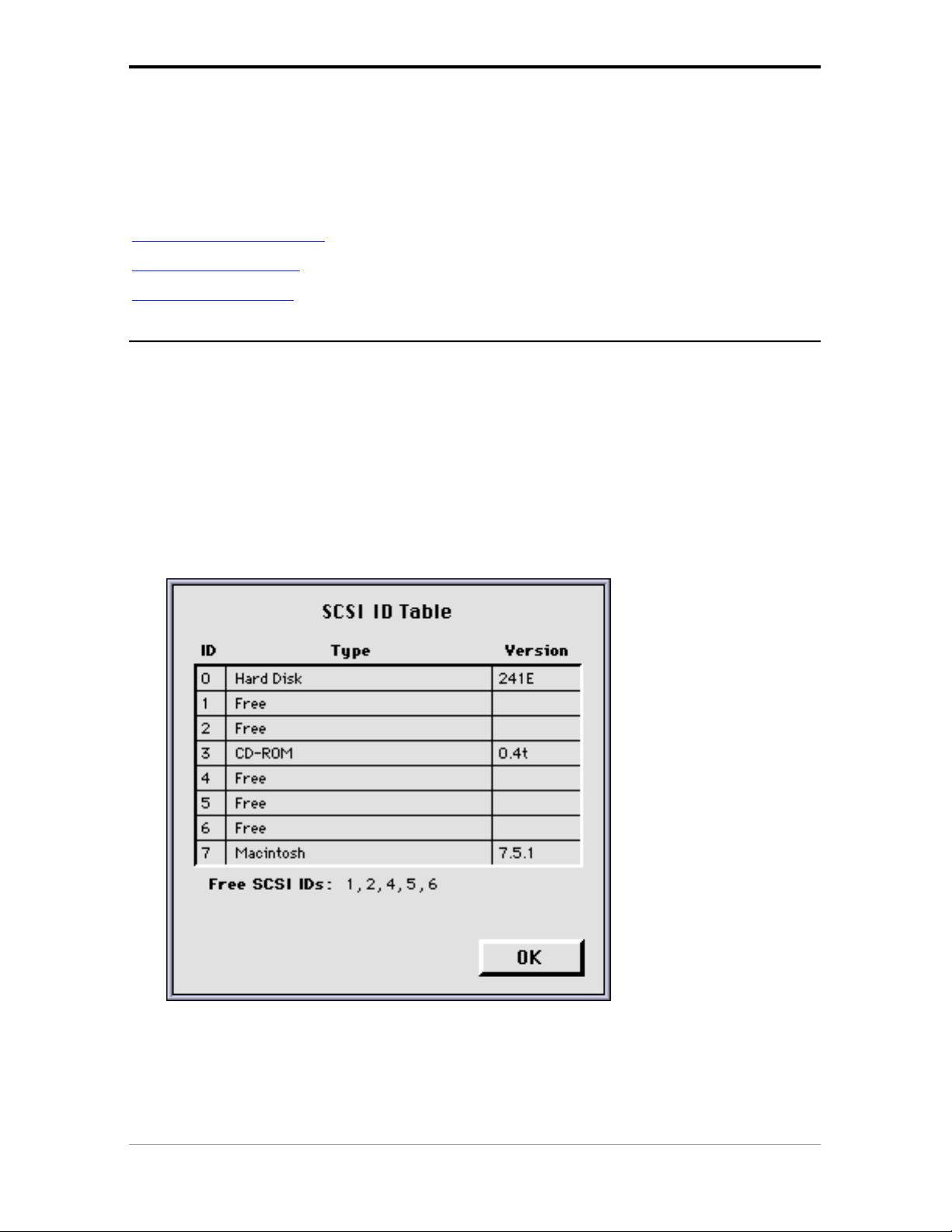
2. Open the SCSI ID Checker.
A dialog box appears with a list of the SCSI ID numbers that are free in your Macintosh
computer.
Your Macintosh always occupies ID 7, its internal hard disk usually occupies ID 0 or ID 1 and CD
ROM usually occupies ID 3. If your Macintosh is equipped with 2 SCSI-busses, the button Next
Bus allows you to switch busses.
Chapter 2 — Installing the scanner 16
Page 17

3. Check if SCSI ID number 2 is free.
Your StudioStar is preset to ID 2.
■ If SCSI ID number 2 is free, click OK to close the SCSI ID Checker.
■ If SCSI ID number 2 is already assigned, you need to set the scanner to a free SCSI ID number.
1. Make sure your scanner is switched off and is disconnected from your computer.
2. Decide on an unassigned SCSI ID number.
3. Push above or underneath the SCSI ID number until you see the number you want.
Push above the SCSI ID number to decrease the number, push underneath the SCSI ID
number to increase the number.
4. Click OK to close the SCSI ID Checker.
Chapter 2 — Installing the scanner 17
Page 18

Connecting the scanner
Before you connect the scanner to your Macintosh, make sure that your scanner as well as your
Macintosh and everything connected to it are switched off.
A terminator and a SCSI cable are supplied with your scanner. Apple Computer, Inc. recommends
using only its proprietary (Black) terminator for the Macintosh IIfx.
Caution: For safety reasons, never use extension cables for power cables.
Always make sure there are no more than two terminators in your SCSI chain, one at the beginning and one at
the end. Some SCSI devices have built-in terminators and must therefore be placed at the beginning or end of
your SCSI chain. Please check the documentation of each of your SCSI devices if you are not sure whether
the device has a built-in terminator. Your StudioStar has no built-in terminator.
If your StudioStar is the only SCSI device to be connected to your Apple Macintosh:
1. Place the terminator on the 50-pin connector of the scanner.
2. Connect the smaller 25-pin end of the SCSI cable to the connector on your Macintosh.
3. Connect the larger 50-pin end of the SCSI cable to the free side of the terminator.
4. Snap the diamond shaped wire clips into the clip brackets to secure the connection.
Chapter 2 — Installing the scanner 18
Page 19

If your StudioStar will be connected to your Apple Macintosh together with other SCSI devices:
■ If you install the scanner at the end of your SCSI chain:
1. Remove the terminator from the last device in the SCSI chain.
2. Connect the 50-pin end of the SCSI cable to the connector that has become available on this
device.
3. Place the terminator on the free 50-pin connector of the scanner.
4. Connect the 25-pin end of the SCSI cable to the free connector of the scanner.
5. Snap the diamond shaped wire clips into the clip brackets to secure the connection.
Chapter 2 — Installing the scanner 19
Page 20

■ If you install the scanner between two other devices:
1. Disconnect your SCSI cable from one of these two devices.
2. Connect the free end of this SCSI cable to the scanner.
3. Connect the 50-pin end of the SCSI cable (the one supplied with your scanner) to the other
adjacent SCSI device.
4. Connect the 25-pin end of the SCSI cable (the one supplied with your scanner) to the scanner.
5. Snap the diamond shaped wire clips into the clip brackets to secure the connection.
Chapter 2 — Installing the scanner 20
Page 21

Testing the connection
You are now ready to perform a test to check if the scanner is correctly connected to your
Macintosh.
Caution: Check if the scanner is properly unlocked.
1. Connect the power cable to the scanner.
Use the correct power cord for the voltage in your area. StudioStar automatically adjusts to any
AC electrical outlet rated from 100V to 240V.
Caution: Make sure that you are using the correct power cable for the voltage in your area.
2. Check if the SCSI cable is properly connected.
3. Switch the scanner on.
The scanner performs a self-test after which the ready indicator (the middle yellow one)
switches on. This takes about 15 seconds or less.
If a malfunction is detected during the self-test, that is, if the ready indicator remains off, refer to
Appendix C, “Troubleshooting”.
4. Switch on any other SCSI devices you may have attached, and wait for them to start up.
5. Switch on your Macintosh.
As it starts up, your Macintosh performs a series of tests to verify the correct system
configuration.
6. Open the SCSI ID checker.
See “Choosing a SCSI ID number” earlier in this chapter.
7. Verify whether the Macintosh sees the scanner at its proper SCSI address.
In case of problems, refer to Appendix C, “Troubleshooting”.
8. Close the SCSI ID checker.
9. Install the FotoLook software following the instructions on the CD-ROM leaflet.
Chapter 2 — Installing the scanner 21
Page 22

Installation for the PC
This section shows you how to set up your StudioStar with your PC. You can find information on
which SCSI interface card to use, instructions for connecting the scanner to your PC and
instructions for testing the connection.
Which SCSI interface card
Choosing a SCSI ID number
Connecting the scanner
Testing the connection
Which SCSI interface card
StudioStar requires a SCSI interface card (for example, the Adaptec card AVA 1502P™ that is
supplied with the scanner) to work with your PC, PC-AT™, 386, 486, or compatible computer.
■ If your PC does not have such a card, you have to install the SCSI interface card that is supplied
with your scanner.
1. Remove the chassis cover of your computer.
2. Locate an unused 16-bit ISA expansion slot.
3. Remove the corresponding slot cover from the back of the computer chassis. Keep the
screw that held the cover in place.
Chapter 2 — Installing the scanner 22
Page 23

4. Align the AVA-1502P SCSI card with the ISA slot, then push it into the slot.
5. Attach the bracket of the SCSI card to the computer chassis, using the screw from the
expansion slot that you removed.
6. Attach the 25-pin connector on the SCSI cable to the connector on your SCSI card.
7. Replace the computer chassis cover, following the instructions in your computer
documentation.
❖ Note: For additional information about the installation of the SCSI card, please refer to the
documentation on the AGFA scanner CD-ROM.
■ If your PC already has a SCSI interface card, you can extend your network.
The scanner software supplied with StudioStar supports ASPI-compatible SCSI interface
cards.
❖ Note: Please check the following documentation:
■ The Read Me file on the PC scanner driver software disk for up-to-date information.
■ The documentation supplied with your SCSI interface card. This will tell you how to install
the card.
■ If you are using third party software, check the documentation supplied with that software
for the SCSI interface cards supported.
Chapter 2 — Installing the scanner 23
Page 24

Choosing a SCSI ID number
Before you connect your StudioStar to your PC, you have to find out which SCSI ID numbers are
already assigned and which numbers are free. To do this, you can use the SCSI ID checker utility.
You will find this utility in the software of Windows 95 or in the software of your SCSI interface card
(SCSI Interrogator).
1. Open the SCSI ID checker utility.
A dialog box appears with a list of the SCSI ID numbers that are free in your PC.
Your PC always occupies ID 7. If your PC is equipped with 2 SCSI-busses, the button Next Bus
allows you to switch busses.
2. Check if SCSI ID number 2 is free.
Your StudioStar is preset to ID 2.
3. ■ If SCSI ID number 2 is free, close the SCSI ID checker utility.
■ If SCSI ID number 2 is already assigned, you need to set the scanner to a free SCSI ID
number.
1. Make sure your scanner is switched off and is disconnected from your computer.
2. Decide on an unassigned SCSI ID number.
Chapter 2 — Installing the scanner 24
Page 25

3. Push above or underneath the SCSI ID number until you see the number you want.
Push above the SCSI ID number to decrease the number, push underneath the SCSI ID
number to increase the number.
4. Close the SCSI ID checker utility.
Chapter 2 — Installing the scanner 25
Page 26

Connecting the scanner
Before you connect the scanner to your PC, make sure that your scanner as well as your PC and
everything connected to it are switched off.
A terminator and a SCSI cable are supplied with your scanner.
Caution: For safety reasons, never use extension cables for power cables.
Always make sure there are no more than two terminators in your SCSI chain, one at the beginning and one at
the end. Some SCSI devices have built-in terminators and must therefore be placed at the beginning or end of
your SCSI chain. Please check the documentation of each of your SCSI devices if you are not sure whether
the device has a built-in terminator. Your StudioStar has no built-in terminator.
Never try to connect the scanner to the serial or parallel port of your PC: you might seriously damage your
equipment if you do.
■ If your PC has a high density SCSI connector, you might need to buy a special cable from your
dealer.
■ If your PC has a 25-pin connector, follow the instructions of “Installation for the Apple
Macintosh: Connecting the scanner”.
■ If your PC has a 50-pin connector and your StudioStar is the only SCSI device to be connected
to your PC:
1. Set the scanner to an unused SCSI ID number between 1 and 6.
For more information, see “Choosing a SCSI ID number” earlier in this chapter.
2. Connect the larger 50-pin end of the SCSI cable to the connector at the rear of your PC.
Use the SCSI cable supplied with the scanner.
3. Place the terminator at the 50-pin connector of the scanner and snap the diamond shaped wire
clips into the clip brackets to secure the connection.
4. Connect the smaller 25-pin end of the SCSI cable to the free connector of the scanner.
Chapter 2 — Installing the scanner 26
Page 27

Chapter 2 — Installing the scanner 27
Page 28

■ If your PC has a 50-pin connector and your StudioStar will be connected to your PC together
n
with other SCSI devices:
If you install the scanner at the end of your SCSI chain:
1. Set the scanner to an unused SCSI ID number between 1 and 6.
For more information, see “Choosing a SCSI ID number” earlier in this chapter.
2. Connect the 50-pin end of the SCSI cable to the connector at the rear of your device.
3. Place the terminator on the 50-pin connector of the scanner. Snap the diamond shaped wire
clips into the clip brackets to secure the connection.
4. Connect the 25-pin end of the cable to the scanner.
Chapter 2 — Installing the scanner 28
Page 29

n
If you install the scanner between two other devices:
Caution: In this configuration you are not allowed to put the terminator on the scanner.
1. Disconnect the two devices between which you want to install the scanner.
2. Set the scanner to an unused SCSI ID number between 1 and 6.
For more information, see “Choosing a SCSI ID number” earlier in this chapter.
3. Connect the 50-pin end of the SCSI cable to the connector at the rear of the adjacent device.
4. Connect the 25-pin end of the cable to the scanner's 25-pin connector.
5. Connect the scanner to the next device in the SCSI chain.
6. Make sure that the last device in the chain is terminated.
In case of problems, refer to Appendix C, “Troubleshooting”.
Chapter 2 — Installing the scanner 29
Page 30

Testing the connection
You are now ready to perform a test to check if the scanner is correctly connected to your PC.
Caution: Check if the scanner is properly unlocked.
1. Connect the power cable to the scanner.
Make sure that you are using the correct power cable for the voltage in your area.
2. Check if the SCSI cable is properly connected.
3. Switch the scanner on.
The scanner performs a self-test after which the ready indicator (the middle yellow one)
switches on. This takes about 15 seconds or less.
If a malfunction is detected during the self-test, that is, if the ready indicator remains off, refer to
Appendix C, “Troubleshooting”.
4. Switch on any other SCSI devices you may have attached, and wait for them to start up.
5. Switch on your PC.
6. Check in 'Show SCSI' if the SCSI interface card sees the scanner at the right address.
7. Install the FotoLook software following the instructions on the CD-ROM leaflet.
Installation of the software
Install the enclosed image editing application software and the enclosed scanning software.
Chapter 2 — Installing the scanner 30
Page 31

Chapter 3 — Using the scanner
This chapter tells you how to place transparent and reflective originals on your scanner.
Placing reflective originals
Placing reflective originals in your document feeder option
Placing transparent originals
Placing reflective originals
You can place a reflective original directly on the scanner’s glass plate.
The following steps explain how to position your reflective original on your scanner.
1. Raise the document cover of the scanner.
If you have acquired and installed a transparency option or a document feeder option, you do
not have to remove it for scanning reflective originals: just raise the transparency option or the
document feeder option.
2. Place the original on the glass plate with its image side down and with its top side against the
middle of the front ruler.
Optical performance of a CCD scanner is always best near the middle of the glass plate.
3. Lower the document cover of the scanner.
The adjustable document cover makes it possible to scan from books and magazines: when
you put a thicker original on the reflective glass plate, the document cover adapts itself to its
thickness.
You are ready to scan now.
Placing reflective originals in your document feeder option
The purpose of the document feeder option is to scan up to 10 pages of text (A4 or US letter) fast
and without interruption. Software like OmniPage Limited Edition® makes it possible to convert
them into most of the commercially used text file formats.
You use your document feeder option as follows: you put a little pile of pages of text (A4 or US
letter) in your document feeder option with the text side up.
Chapter 3 — Using the scanner 31
Page 32

Placing transparent originals
Caution: Always use the template for scanning transparent originals. Make sure that the calibration slit is
not covered by the transparent original and that it is clean.
You need the transparency option to scan transparent originals. You use it as follows:
1. Install the transparency option: refer to Appendix A, “Using the transparency option”
2. Raise the transparency option.
3. Place the original that you want to scan on the glass plate with the emulsion down and with its
top side towards the calibration slit. This position guarantees the best quality. Make sure that
the calibration slit in the frame is at the front side (standing in front of the scanner) and that it is
free. To see where the calibration slit is situated, you have to use the template that is delivered
with the transparency option.
If you place more than one slide on the glass plate (for batch scanning), position them as close
to the center line as possible to optimize quality.
4. Lower the transparency option.
You are ready to scan now.
Chapter 3 — Using the scanner 32
Page 33

Appendix A — Using the transparency option
The transparency option is an optional item that allows you to scan transparencies. This appendix
describes the procedure for installing the transparency option if you have bought one for your
StudioStar.
Unpacking the transparency option
Unlocking the transparency option
Connecting the transparency option
Unpacking the transparency option
The first thing to do is to make sure you have everything you are supposed to.
1. Open the packing box and take out all the items.
2. Check each item to make sure that you have everything and that there is no visual defect.
If something is missing, contact your dealer.
3. Remove the plastic wrapping and the packing materials from the transparency option.
4. Fill out the Warranty and Registration card. You will find the product serial number on the
identity label on the rear of your transparency option.
❖ Note: Save the packing materials so that you can repack the transparency option to protect it if
you have to move it over long distances.
Appendix A — Using the transparency option 33
Page 34

Unlocking the transparency option
Unlock the transparency option before connecting it to the scanner.
1. Locate the locking screw at the base of the transparency option.
2. Turn the hand screw clockwise.
Your transparency option is unlocked.
Connecting the transparency option
1. Check if your scanner and your transparency option are properly unlocked.
2. Turn off your scanner.
3. Turn off your computer.
4. If the document feeder option is installed, disconnect it from your scanner.
5. Place the transparency option as shown in the figure.
Appendix A — Using the transparency option 34
Page 35

6. Lower the transparency option.
Appendix A — Using the transparency option 35
Page 36

7. Connect the male DB 15-pin connector of the transparency option to the female DB 15-pin
connector at the rear of the scanner.
8. Place the template that came with your transparency option on the glass plate as shown in the
figure.
Caution: Make sure that the clear opening rectangle of the template faces the front of the scanner and is not
covered by the transparent originals.
Appendix A — Using the transparency option 36
Page 37

The transparency option is ready for use.
9. Turn your scanner on.
10. Turn your computer on.
Appendix A — Using the transparency option 37
Page 38

Appendix B — Using the document feeder option
This appendix gives information on the document feeder option and describes how to install,
operate and maintain it.
About your document feeder option
Installing the document feeder option
Checkout
Before you begin
Installation
Operating the document feeder option
Paper loading
Correcting paper jams
Maintaining the document feeder option
Cleaning and replacing the guide flap
Roller cleaning
About your document feeder option
The ADF Automatic Document Feeder is a companion sheet feeder for your StudioStar. It allows
automatic scanning of up to 10 sheets. The dimension of the document can be as large as 8.5" x
14". Sheets to be scanned are fed from a stack in the ADF's input tray, guided past the scanner's
image sensor, and placed in the feeder's output tray.
The ADF mounts onto the scanner in place of a document cover, using the original document guide
holes of your scanner. The feeder is preloaded by spring plungers so that it can be lowered into
position for auto-feed or lifted off to allow use of the flatbed.
The ADF is a must for high-volume document processing with your StudioStar. It increases
operating convenience and efficiency in multi-page scanning and OCR application.
Appendix B — Using the document feeder option 38
Page 39

Installing the document feeder option
Checkout
The ADF is delivered in assembled form, ready to be mounted onto the scanner. The first thing to
do is to make sure you have everything you are supposed to.
1. Open the packing box and take out all the items.
The ADF package includes the ADF and the Warranty Card.
2. Check each item to make sure that you have everything and that there is no visual defect.
If something is missing, contact your dealer.
3. Remove the plastic wrapping and the packing materials from the document feeder option.
4. Fill out the Warranty card. You will find the product serial number on the identity label at the rear
of your document feeder option.
❖ Note: Save the packing materials so that you can repack the document feeder option to protect
it if you have to move it over long distances.
Before you begin
Follow these steps before installing the ADF:
1. Install the scanner as described in this Owner's guide.
2. Make sure that the scanner, its peripherals, and the computer are all powered off. Unplug the
scanner's power cord.
Installation
You install the document feeder option as follows:
1. Check if your scanner is properly unlocked.
2. Turn off your scanner.
3. Turn off your computer.
4. If the transparency option is installed, disconnect it from your scanner, for it uses the same
connector.
5. Pull out the two pins holding the scanner's document cover and lift off the cover.
6. Place the ADF on top of the scanner. Insert the guide pins into the holes originally used by the
scanner's document cover.
Appendix B — Using the document feeder option 39
Page 40

Appendix B — Using the document feeder option 40
Page 41

7. Connect the male DB 15-pin connector of the document feeder option to the female DB 15pin connector at the rear of the scanner. Secure the connector by tightening its retaining
screws.
8. After the ADF is securely attached, swing the paper support up to over 60 degrees. The paper
support should stay in the raised position by itself.
9. Press the locking button at the right side of the ADF.
The upper housing of the ADF popes up a little.
Appendix B — Using the document feeder option 41
Page 42

10. Raise the transportation module.
Appendix B — Using the document feeder option 42
Page 43

11. Check the transparent guide flap on the base. Make sure one part of the guide flap is securely
attached to the base.
guide flap
12. Close the ADF.
13. Turn your scanner on.
14. Turn your computer on.
Software like OmniPage Limited Edition makes it possible to convert the scanned sheets of
text into most of the commercially used text file formats.
Operating the document feeder option
When the ADF is installed and the computer and the ADF are powered on, start up the scanner
application software.
Appendix B — Using the document feeder option 43
Page 44

Paper loading
Before loading the ADF, check to see if the transparent guide flap is firmly attached in place,
and the protective film is removed as described in “Installing the document feeder option” . If it
is not, scanned documents will jam up against the base of the feeder, rather than being moved
into the output tray.
To load documents:
1. Pull the paper support up, this prevents the paper sheets not to bend down.
2. Place the documents in the input tray with the side to be scanned facing down.
3. Make sure the pages are aligned in the center with the two guide arms.
4. If the documents are less than 8.5" wide, use the sliding guide arms to hold the stack in
place.
Appendix B — Using the document feeder option 44
Page 45

Correcting paper jams
To remove jammed pages:
1. Press the ADF locking button.
The ADF transportation module is disengaged.
2. Lift the transportation module, then grasp both free corners of the jammed sheet and pull it out
slowly.
3. Lower the ADF transportation module down and snap to close it.
Appendix B — Using the document feeder option 45
Page 46

Maintaining the document feeder option
Cleaning and replacing the guide flap
The guide flap on the underside of the ADF keeps documents at the correct scanning position and
guides them into the output tray after scanning. To prevent printing ink and other contaminants from
accumulating on the flap and interfering with image quality, wipe it periodically with an ink-free cloth
or swab cotton swab moistened with industrial alcohol.
After prolonged use, the surface of the flap may become scratched. This causes lines to appear in
scanned images that can create OCR errors. Should the scratches appear, detach the flap and
replace it by a new one. For a new guide flap, please contact your dealer.
Roller cleaning
Prolonged use of the ADF may result in accumulation of ink and other contaminants on the feeder's
input roller, reducing the roller's efficiency. Check for dirt on the roller if the ADF starts to have
trouble pulling paper through properly. The input roller should be cleaned periodically using a lintfee cloth or swab moistened with ethylene chloride.
❖ Note: Do not attempt to turn the roller while cleaning it; this may damage the ADF's drive
mechanism.
Appendix B — Using the document feeder option 46
Page 47

Appendix C — Troubleshooting
This appendix explains some common problems you may come across when starting up or using
your StudioStar.
The computer screen displays scanner calibration error.
■ The calibration slit is covered by your transparent original. You did not use the template or you
used it incorrectly. This can only happen when you are in transparency mode.
The ready indicator (yellow) on the scanner operating panel fails to light up.
■ Check if you have removed the lock.
■ Check the scanning lamp in the scanner. If the lamp flickers, dims or goes off, please contact
your dealer.
■ If the temperature is low, leave the scanner on for several minutes to let it warm up. Turn the
power off and then on again. If both lights still go off, contact your dealer.
The scanner or Transparency option lamp flickers, dims, or fails to come on.
■ The scanning lamp is failing or has failed and needs to be changed. Contact your dealer.
The scanner driver software returns a “Scanner not ready” or similar message.
■ Verify the power connection to the scanner
■ Check that the power switch is turned on.
■ Check the Installation procedure, to see if you followed the instructions. Pay special attention
to the setting of the SCSI ID number.
■ Verify the terminators and the cables. If there is a problem with a cable or with the SCSI board of
the scanner, contact your dealer.
■ Disconnect all SCSI devices and connect them one by one, beginning with the scanner, to
identify the device that causes the problem.
The scanner does not start up.
■ Contact your dealer.
The scanner makes a banging noise and nothing moves under the glass plate.
■ The scanner was not properly unlocked. Immediately switch the scanner off and unlock
properly, or call your dealer.
Appendix C — Troubleshooting 47
Page 48

The ready indicator light (yellow) on the scanner’s operating panel remains
blinking or goes off after the power-up sequence. (= 15 seconds)
A malfunction has been detected by the scanner.
■ Check if you have unlocked the scanner. If this can not be the problem please contact your
dealer.
The power indicator (green) fails to light up.
■ Verify the power connection to the scanner.
■ Check if the power switch is turned on.
■ If you are sure that the scanner is powered on, contact your dealer.
The workstation does not start up. If your workstation is an Apple Macintosh a
little floppy disk with a question mark appears on your screen.
Your workstation cannot find its hard disk due to a conflict with the SCSI ID numbers of the devices
you have attached.
■ Disconnect all SCSI devices (except the start-up disk) and connect them one by one,
beginning with the scanner, to identify the device that causes the problem (switch all devices
off before breaking or making connections).
The scanner software cannot find the scanner
After opening the Scan dialog box, a message appears telling that no scanner is connected,
although the scanner is connected.
■ Check the Installation procedure, to see if you followed the instructions. Pay special attention
to the setting of the SCSI ID number.
■ Maybe you did not wait long enough for all SCSI devices to start up, before you switched your
workstation on. Therefore, try restarting your workstation. If this doesn’t help,
■ Disconnect all SCSI devices and connect them one by one, beginning with the scanner, to
identify the device that causes the problem.
The scanner reports errors during scanning (Apple Macintosh)
■ Check the presence of the SCSI terminator. If this can not be the problem, please contact your
dealer.
Appendix C — Troubleshooting 48
Page 49

Appendix D — Technical information
This appendix provides some technical information about your StudioStar, about the transparency
option and about the document feeder option.
StudioStar specifications
Transparency option specifications
Document feeder option specifications
StudioStar specifications
Scanner type: Desktop, flatbed, one pass
Maximum resolution:
- optical 600 dpi horizontal x 1200 dpi vertical
- through interpolation 2400 dpi horizontal x 2400 dpi vertical
Sample depth: 10 bits for gray, 30 bits for colour
Scanning speed:
- line-art 5 ms per line
- halftone 5 ms per line
- gray 5 ms per line
- colour 6,5 ms per line
Maximum scanning area: 211 mm x 355 mm (8,5" x 14")
Lamp: cold cathode
Warm up time: 15 seconds
Power supply:
- line voltage 100 to 240 V
- frequency 47 to 63 Hz
Dimensions:
- length:
- width:
- height: 143 mm (5.6")
- weight: 8 kg (17.6 lb)
545 mm (21.5")
386 mm (15")
Options: Transparency option
Document feeder option
Appendix D — Technical information 49
Page 50

Interface: SCSI-2 interface, 25-pin and 50-pin SCSI-
connector
Transmission speed: 2 Mb/s
Environment:
- operating temperature 10 °C to 40 °C (50 F to 104 F)
- relative humidity 20% to 85%
- surrounding space
10 cm (4") on each side, 15 cm (6") at the
rear side
Transparency option specifications
System: Moving light source
Maximum resolution: 600 dpi horizontal x 1200 dpi vertical
Scanning area: Maximum 201 mm x 252 mm (8" x 10")
Lamp: cold cathode
Power supply: from the scanner
Interface: 15-pin cable with connector to scanner
Dimensions:
- length:
- width:
- height: 57.55 mm (2")
- weight: 4.7 kg (10 lb)
Environment:
- operating temperature 10 °C to 40 °C (50 F to 104 F)
- relative humidity 20% to 85%
- surrounding space
515.54 mm (20")
328.54 mm (13")
10 cm (4") on each side, 15 cm (6") at the
rear side
Document feeder option specifications
Capacity: 10 sheets of copy bond paper (unfolded)
Paper size: 16 to 24 lb. bond paper
- minimum 140 mm x 140 mm (5.5" x 5.5")
- maximum
216 mm x 356 mm (8.5" x 14") (US legal
size)
Accuracy: Paper skew: 1 degree
Connector: 15-pin sub miniature D-shell
Appendix D — Technical information 50
Page 51

Physical:
- footprint:
298 mm x 468 mm (11.73" x 18.42")
- input tray height: 77 mm (3.03")
Dimensions:
- length: 435 mm (17")
- height: 77 mm (3")
- weight: 2.3 kg (5.0 lb.)
Power supply: from the scanner
Operating conditions:
- temperature 10 °C to 40 °C (50 F to 104 F)
- relative humidity 20 % to 80 %
❖ Note: Technical specifications are subject to change without notice.
Appendix D — Technical information 51
Page 52

Appendix E — StudioStar regulation compliance
Safety regulations
Electromagnetic interference
Safety regulations
StudioStar and its options are designed to comply with:
UL 1950-D3
CSA C22.2 No. 950 - M89 D3
VDE 805
IEC 950
GS approved
CSA c22.2 No. 950-M89
EN 60950
UL Safety Statement
Instructions for power supply cord selection:
For modules set at 115V:
Use a UL listed, Type SVT or SJT cord, three conductor, rated 10 A 125 V, not to exceed 15ft in
length.
Caution: For the reason of safety, besides the personal maintenance mentioned in this operation manual,
don’t try to remove any mechanical parts or any electronic devices. If you need service, our dealer and
service offices are available to help you.
FTZ: Bescheinigung des Herstellers/Importeurs
Hiermit wird bescheinigt dass der Image Scanner in Übereinstimmung mit den Bestimmungen der
vgf 1046/1984 funk-entstört ist.
Der Deutschen Bundespost wurde das inverkehrbringen dieses Gerätes angezeigt und
Berechtigung zur Überprüfung der Serie auf Einhaltung der Bestimmungen eingeraumt.
TÜV: Wichtige Sicherheitshinweise
1. Bitte Lesen Sie sich diese Hinweise sorgfältig durch.
2. Um eine Beschädigung des Gerätes zu vermeiden sollten Sie nur Zuberhörteile verwenden,
die vom Hersteller zugelassen sind.
3. Das Gerät ist vor Feuchtigkeit zu schützen.
Appendix E — StudioStar regulation compliance 52
Page 53

4. Bei der Aufstellung des Gerätes ist auf sicheren Stand zu achten. Ein Kippen oder Fallen
könnte Verletzungen hervorrufen. Verwenden Sie nur sichere Standorte und beachten Sie
die Aufstellhinweise des Herstellers.
5. Die Belüftungsöffnungen dienen zur Luftzirkulation die das Gerät vor Überhitzung schütz.
Sorgen Sie dafür, daß diese Öffnungen nicht abgedeckt werden.
6. Die Netzanschulßsteckdose muß aus Gründen der elektrischen Sicherheit einen
Schutzleiterkontakt haben.
7. Durch die Lüftungsöffnungen dürfen niemals Gegenstände oder Flüssigkeiten in das Gerät
gelangen. Dies könnte einen Brand bzw. elektrischen Schlag auslösen.
8. Öffnen Sie niemals das Gerät. Das Gerät darf aus Gründen der elektrischen Sicherheit nur von
authorisiertem Servicepersonal geöffnet werden.
9. Die Steck dose sollte nahe dem Gerät und leicht zugänglich sein.
Electromagnetic interference
StudioStar is designed to comply with:
VDE 0871, class B
VDE 0875, level N
FCC 20718, part 15, subpart B, class B
Federal Communications Commission Radio Frequency Interference
Statement.
Note: This equipment has been tested and found to comply with the limits for a Class B digital
device, pursuant to Part 15 of the FCC Rules. These limits are designed to provide reasonable
protection against harmful interference when the equipment is operated in a residential installation.
This equipment generates, uses, and can radiate radio frequency energy and if not installed and
used in accordance with the instruction manual may cause harmful interference to radio
communications. However, there is no guarantee that interference will not occur in a particular
installation. If this equipment does cause harmful interference to radio or television reception, which
can be determined by turning the equipment off and on, the user is encouraged to try to correct the
interference by one or more of the following measures:
■ Reorient or relocate the receiving antenna.
■ Increase the separation between the equipment and receiver.
■ Connect the equipment into an outlet on a circuit different from that to which the receiver is
connected.
■ Consult the dealer or an experienced radio TV technician for help.
Notice:
(1) The changes or modifications not expressly approved by the party responsible for compliance
could void the user’s authority to operate the equipment.
(2) Shielded interface cables and AC power cord, if any, must be used in order to comply with the
emission limits.
Appendix E — StudioStar regulation compliance 53
Page 54

Canadian department of Communications
This digital apparatus does not exceed the Class B limits for radio noise emissions from digital
apparatus set out in the Radio Interference Regulations of the Canadian Department of
Communications.
Le présent appareil numérique n’émet pas de bruits radioélectriques dépassant les limites
applicables aux appareils numériques (de la classe B) prescrites dans le Règlement sur le brouillage
radioélectrique édicté par le ministère des Communications du Canada.
Appendix E — StudioStar regulation compliance 54
 Loading...