

Page 1

DD+DIS135.02E
Machine specific tools, software tools and auxiliary equipment
Chapter 3.2
Repair and Service
List of Contents
1 System Configuration.............................................1
1.1 Configuration via Configuration Viewer ............................. 1
1.1.1 Configure Digitizer .........................................................................1
1.1.2 Configure Gateway........................................................................2
1.1.3 Configure ID-Viewer ......................................................................4
1.1.4 Configure Medical Printers ............................................................5
1.1.5 Configure Destinations ..................................................................7
1.2 Configuration via CPF-File................................................. 10
1.2.1 CPF-File created by CCM............................................................10
1.2.2 Digitizer CPF-File (also called partial CPF-File)...........................11
1.3 Configuration of mixed environments .............................. 12
1.4 Configuration Cloning ........................................................ 12
1.4.1 Cloning an ADC-QS Server .........................................................12
1.4.2 Cloning User Settings of Viewers
(for ADC QS Server and Client)...................................................13
2 License Management............................................14
2.1 Adding Licenses ................................................................. 15
3 Creation of an ADC QS Restore CD.....................16
3.1 General ................................................................................ 16
3.2 Requirements...................................................................... 16
3.3 Procedure ............................................................................ 16
3.3.1 Testing the recorded Restore CD ................................................18
3.4 Restore Toolkit Version 2.5 – Potential Errors
and Solutions ...................................................................... 19
4 Agfa DICOM bridge ...............................................20
5 ID-Viewer GUI and DICOM Modality
Worklist GUI ..........................................................20
6 RIS Link .................................................................20
7 WebAdmin.............................................................21
Edition 1, Revision 0 ADC QS 2.1.xx Chapter 3.2 / I
(Type 4406/421)
Page 2

Repair and Service
Machine specific tools, software tools and auxiliary equipment
DD+DIS135.02E
8 Setup of a Secure User (optional – only on
Customer Request) ...............................................23
8.1 Add Secure User..................................................................23
8.2 Remove Secure User...........................................................24
9 Installing ADC-QS into an Existing NT Domain..25
9.1.1 ADC-QS System Name ............................................................ 25
9.1.2 Add ADC-QS System to Domain .............................................. 25
9.1.3 Adding Domain User to Local System....................................... 26
9.1.4 Logging onto the Domain.......................................................... 28
9.1.5 Notes:....................................................................................... 28
10 Virus Scanner Software........................................29
10.1 Settings to be changed ...................................................29
10.1.1 Settings deviating from default ................................................. 29
10.2 Overview of all Settings ..................................................31
10.2.1 NetShield v4.5 for Server w/SP1 .............................................. 31
10.2.2 NetShield v4.5 for Client w/SP1................................................ 32
10.2.3 Virus Scan NT v5.1 for Client ................................................... 34
AGFA DICOM Bridge, Version 2.0b
(User Guide)
Configuration Viewer Software
(User Manual)
Supported Printers
DD+DIS138.02E
Chapter 3.2 / II ADC QS 2.1.xx Edition 1, Revision 0
(Type 4406/421)
Page 3
DD+DIS135.02E
Repair and Service
Machine specific tools, software tools and auxiliary equipment
1 System Configuration
There are three possibilities to configure ADCQS.2.1. All three possibilities
have their justification if they are applied for the purpose they are designed for:
• Configuration Viewer Æ Standard configuration tool for the ADCQS for
onsite configuration, configuration changes and enhancements
• CPF-file created by CCM ToolÆ Can be used after initial setup to save
configuration work; should not be used later on anymore for configuration
changes or enhancements
• Cloning Æ Allows to duplicate stations; this helps especially to reduce the
GUI configuration work if more than one Viewer has to be set up similarly.
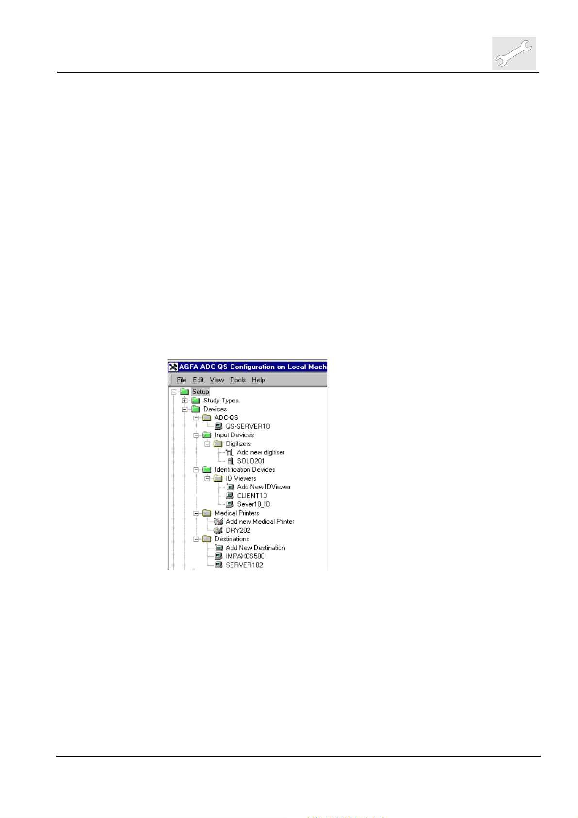
1.1 Configuration via Configuration Viewer
The Configuration Viewer is the ideal tool on ADC QS to change or modify the
configuration of the system.
It is explained in detail in the Configuration Viewer Software - User Manual,
separately added in this chapter 3.2 .
Here we mainly focus on the Device configuration.
1.1.1 Configure Digitizer
(1) To Configure Digitizer select at Configuration Viewer
<Setup>
<Devices>
<Input Devices>
<Digitizers>
(2) Double click on <Add new digitizer>
(3) Select digitizer model and click <Next>
Edition 1, Revision 0 ADC QS 2.1.xx Chapter 3.2 / 1
(Type 4406/421)
Page 4

Repair and Service
Machine specific tools, software tools and auxiliary equipment
DD+DIS135.02E
(4) Enter network information at tab Network and AE Title at tab DICOM
at tab Image the image type can be looked up.
(5) Click <Finish> to save configured digitizer
To transfer the configuration information from the ADC QS to the digitizer
at the end of the configuration session a Digitizer CPF-file (partial CPF-file)
must be created and installed on the digitizer (see further explanation
below, at 1.2.2 of this chapter).
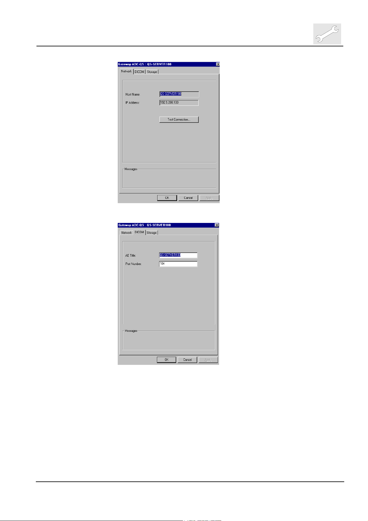
1.1.2 Configure Gateway
(1) To Configure Gateway select at Configuration Viewer
<Setup>
<Devices>
<ADC QS>
<Server Hostname>
(2) Double click on host name of the Server e.g. <QS_SERVER_10>
(3) Check host name and IP-Address at tab Network. Network settings are
taken over from “Windows NT Network Settings”. To test TCP/IP
connection you can press <Test Connection…> button.
Chapter 3.2 / 2 ADC QS 2.1.xx Edition 1, Revision 0
(Type 4406/421)
Page 5
DD+DIS135.02E
Repair and Service
Machine specific tools, software tools and auxiliary equipment
(4) Enter AE Title at tab DICOM.
At tab Storage the storage path can be looked up.
(5) Click <OK>
Edition 1, Revision 0 ADC QS 2.1.xx Chapter 3.2 / 3
(Type 4406/421)
Page 6

Repair and Service
Machine specific tools, software tools and auxiliary equipment
1.1.3 Configure ID-Viewer
(1) To Configure ID-Viewer select at Configuration Viewer
<Setup>
<Devices>
<Identification Devices>
<ID Viewers>
(2) Double click on <Add new ID Viewer>
(3) Enter host name in caps (key sensitive), IP-Address and name
DD+DIS135.02E
(4) Click <Next>
(5) Check respectively uncheck “Use Direct_ID” check box and click
<Finish>
Chapter 3.2 / 4 ADC QS 2.1.xx Edition 1, Revision 0
(Type 4406/421)
Page 7
DD+DIS135.02E
Machine specific tools, software tools and auxiliary equipment
Select only one ID-Station in a cluster for DirectID. To communicate the IDViewer to run DirectID on ADC SOLO digitizer, a Digitizer CPF-File (partial
CPF-file) has to be created and imported on the digitizer. In addition
DirectID has also to be activated in the ADC SOLO digitizer to make it
working.
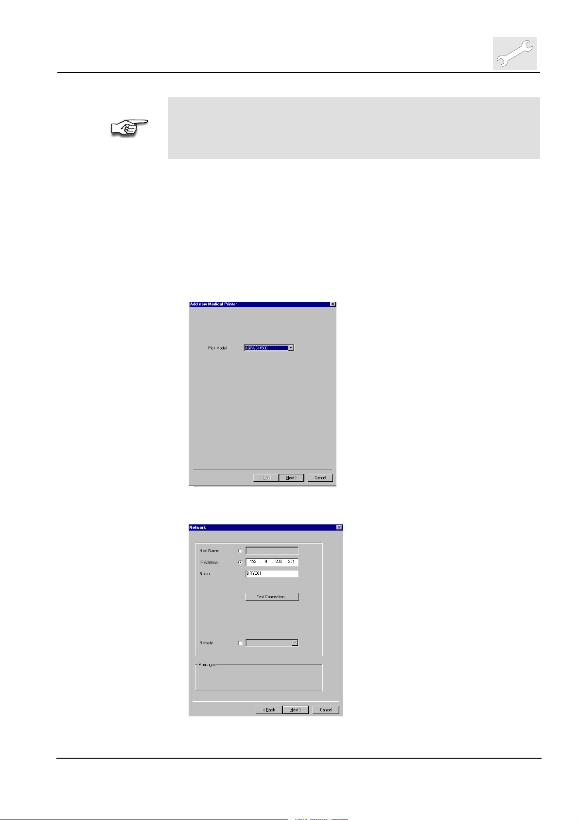
1.1.4 Configure Medical Printers
(1) To Configure Medical Printers select at Configuration Viewer
<Setup>
<Devices>
<Medical Printers>
(2) Double click on <Add new medical printer>
(3) Select printer model, click <Next>
Repair and Service
(4) Enter IP_address and name of printer, click <Next>
Edition 1, Revision 0 ADC QS 2.1.xx Chapter 3.2 / 5
(Type 4406/421)
Page 8
Repair and Service
Machine specific tools, software tools and auxiliary equipment
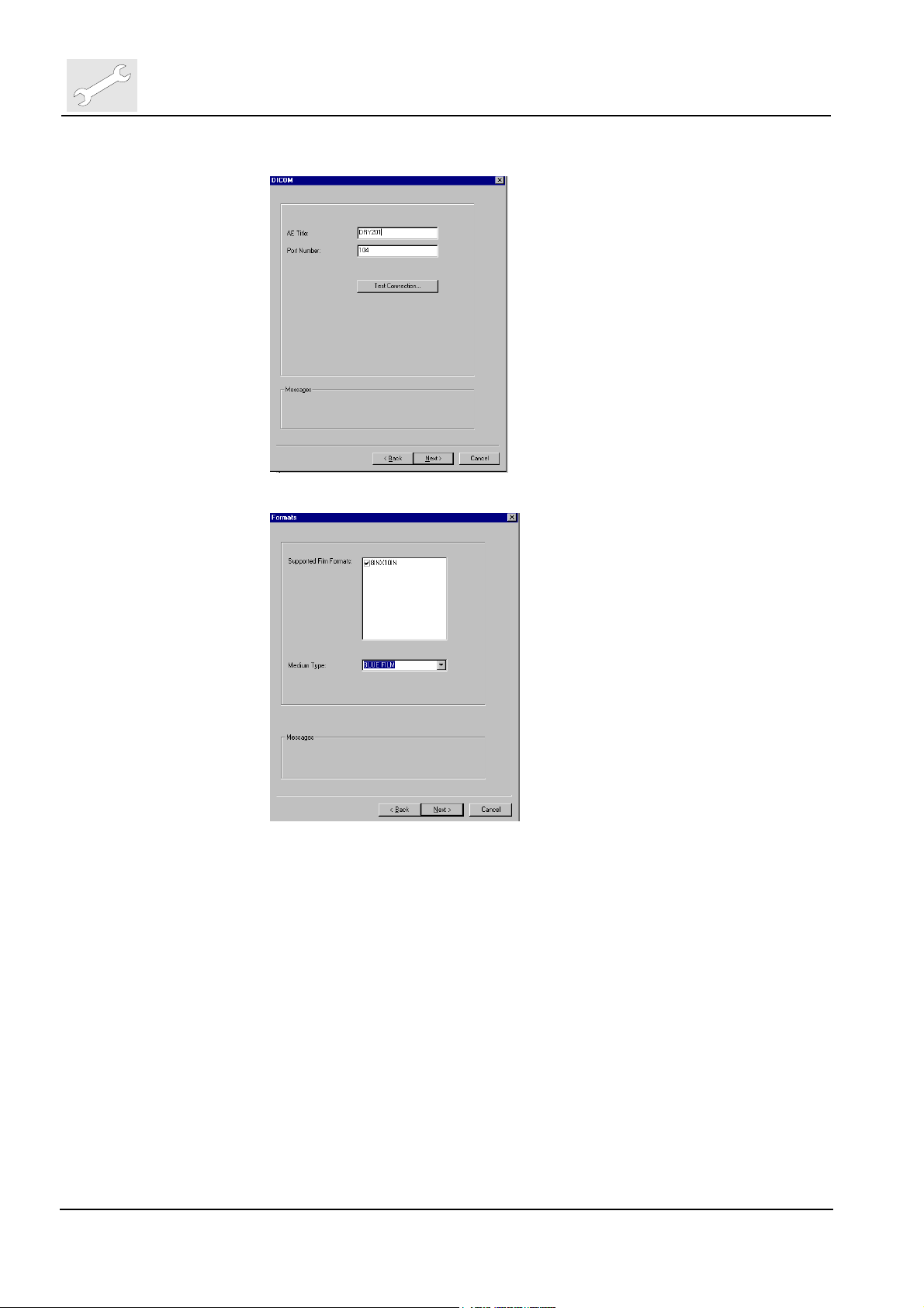
(5) Enter AE-title, click <Next>
(6) Select supported formats and medium type, click <Next>
DD+DIS135.02E
Chapter 3.2 / 6 ADC QS 2.1.xx Edition 1, Revision 0
(Type 4406/421)
Page 9
DD+DIS135.02E
Repair and Service
Machine specific tools, software tools and auxiliary equipment
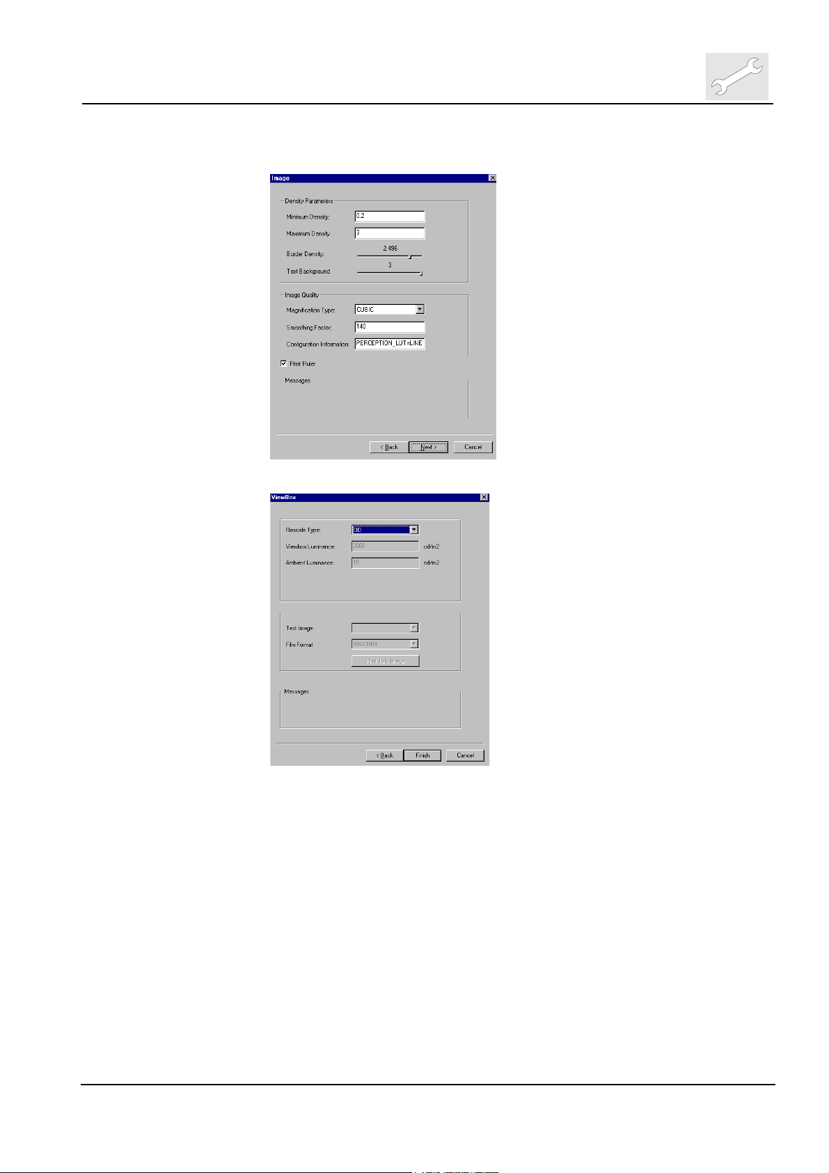
(7) Check resp. change density parameters and image quality settings, click
<Next>
(8) Select Rescale type and previously checked film formats
(9) Click <Finish> to confirm medical printer configuration.
(10) On an ADCQS Client Station the printers have to be installed just as
NT-Network Printers.
1.1.5 Configure Destinations
(1) To Configure Destination select at Configuration Viewer
<Setup>
<Devices>
<Destinations>
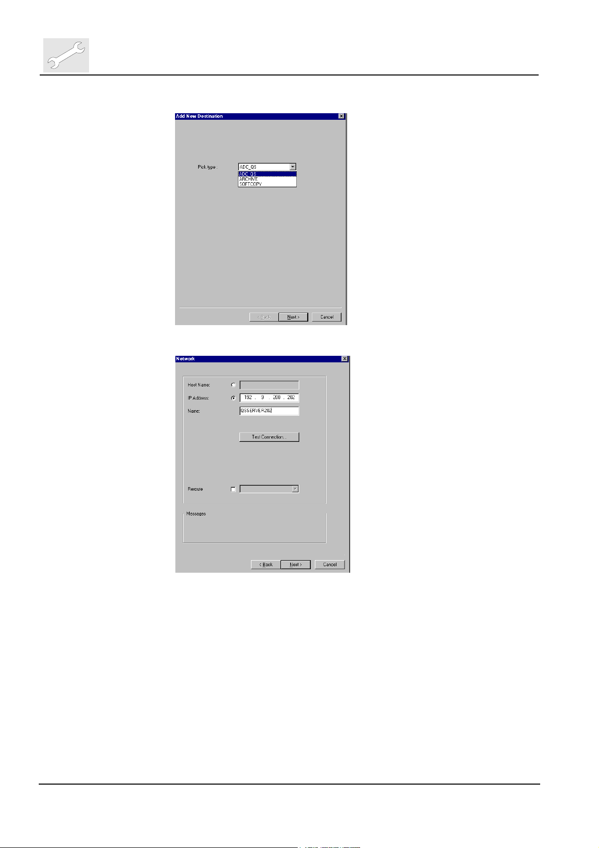
(2) Double click on <Add new destination>
Edition 1, Revision 0 ADC QS 2.1.xx Chapter 3.2 / 7
(Type 4406/421)
Page 10
Repair and Service
Machine specific tools, software tools and auxiliary equipment
(3) Select destinations type (ADC QS Server, Archive or Softcopy)
DD+DIS135.02E
(4) Enter IP_address and name of the destination
Chapter 3.2 / 8 ADC QS 2.1.xx Edition 1, Revision 0
(Type 4406/421)
Page 11

DD+DIS135.02E
Machine specific tools, software tools and auxiliary equipment
(5) Enter AE-title and select DICOM version
Repair and Service
(6) Click <Finish> for Server as new destination, for Archive and Softcopy
one dialog more will appear.
Archive:
Select Resolution and post processing
Edition 1, Revision 0 ADC QS 2.1.xx Chapter 3.2 / 9
(Type 4406/421)
Page 12
Repair and Service
Machine specific tools, software tools and auxiliary equipment
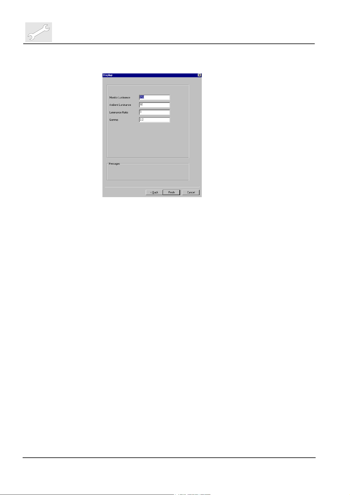
Softcopy:
Enter display settings
DD+DIS135.02E
1.2 Configuration via CPF-File
In conjunction with ADC QS we distinguish between two different CPF-files:
• The CPF-file created by means of CCM-Tool.
• The Digitizer CPF-File or also called partial CPF-File.
1.2.1 CPF-File created by CCM
This is the file which is used to configure VIPS, PRID and the CR-Digitizers.
This file can be used as a good basis to get started after initial setup of an
ADC QS Cluster. To configure ADC QS with the CCM created CPF-file
proceed as follows:
(1) Carry out Configuration work with CCM tool.
Please note that the hostname for an ADC QS Server has to be entered in
capital letters (the simplest is here to use the same term for hostname,
station name and DICOM_AE title).
(2) Save CPF-file on floppy
(3) Startup Configuration Viewer on ADC QS Server
(4) Enter floppy and Select “File-Æ Import CPF”
(5) At the end of the import you maybe asked to synchronize printers. Just
select a printer and press “Install”. Repeat this until all printers are
installed.
(6) Reset ADC QS
Chapter 3.2 / 10 ADC QS 2.1.xx Edition 1, Revision 0
(Type 4406/421)
Page 13

DD+DIS135.02E
Repair and Service
Machine specific tools, software tools and auxiliary equipment
ADC QS supports IP_address resolution via DNS (or Netbui). However
most of the other AGFA devices (digitizers, printers, etc.) do not support
this resolution method.
During importing a CPF-file the ADC QS reads the IP_addresses of that
different device in the CPF-file and tries to resolve the corresponding
hostname via DNS (or Netbui). If it is successful finding a corresponding
hostname, it will fill it in into the “Hostname” field.
If it is not successful, it will fill in the IP_address into the “Hostname” field.
The next time you export Digitizer CPF-file (partial CPF-file) you will have
the IP_address filled in for hostname and IP_address.
Therefore it is advised after importing a CPF-file created by CCM to select
Setup Æ Devices Æ Input Devices Æ Digitizer. There you select the
Network tab and change the hostname field (containing the IP_address)
into the actual hostname of the digitizer.
Please note that importing a CPF-file on the ADC QS Server deletes all
configuration information setup before. That is:
• The whole device configuration
• The whole examination configuration
• The whole image processing configuration
• The whole dose monitoring statistics
Therefore we recommend to use the CPF-file import only for the initial
startup.
1.2.2 Digitizer CPF-File (also called partial CPF-File)
The need for a Digitizer CPF-file came up together with ADC QS.2.1. The
reason why we need that file is because in a pure ADC QS environment the
Configuration Viewer is used to configure ADC QS. However the CR-Digitizers
still need a CPF-file to be configured.
ADC QS produces that file itself. It must only be used for Digitizers, as it
contains only part of the information a CCM created CPF-file contains.
To create a Digitizer CPF-File you have to perform the following steps:
(1) Carry out Configuration work with Configuration Viewer
(2) Put floppy to floppy drive of ADC QS station
(3) Select at Configuration Viewer
<File>
<Export AGFA DICOM Digitizer CPF>
(4) Click <Export CPF> to browse folder A:\ to save CPF-file on floppy
(5) Install the CPF-file from floppy in the digitizer
Edition 1, Revision 0 ADC QS 2.1.xx Chapter 3.2 / 11
(Type 4406/421)
Page 14

Repair and Service
Machine specific tools, software tools and auxiliary equipment
1.3 Configuration of mixed environments
ADC QS.2.1 can also be installed in mixed environments with PRID and VIPS.
For the initial setup the same CPF-file, created by the CCM-Tool can be used.
If this file is imported into ADC QS you will find in the Configuration Viewer
under Setup Æ Devices Æ Destination also the VIPS stations as possible
destinations. This destinations must be deleted as they are not able to receive
data from an ADC QS.
For later configuration changes it is advised to use Configuration Viewer for
ADC QS and CCM-Tool for VIPS and PRID related changes. This may require
also manual adaptation between the different configuration methods.
1.4 Configuration Cloning
Depending what is to be done two procedure to clone ADC QS devices maybe
applied. They also can be used in combination.
DD+DIS135.02E
1.4.1 Cloning an ADC-QS Server
This is normally done when configuration from one Server should be
transferred to another Server, i. e. into another cluster. Here only the
configuration data kept in the database is transferred. The procedure is as
follows:
(1) Start Configuration Viewer on Source Server*
(2) Select
<File>
<Export Configuration to xml-file>
This may take some minutes depending on the size of the configuration.
(3) Stop ADC QS application on Target Server
(4) Start Configuration Viewer on Target Server
(5) Select
<File>
<Import Configuration from xml-file>
This may take some minutes depending on the size of the configuration;
app. 5 min per 0.5Mb size of xml-file.
(6) Check Gateway configuration in Configuration Viewer and adapt if
necessary to the requirements on the Target Server
(Setup Æ Devices Æ ADCQS Æ <Server name>). Parameters to be
adapted maybe hostname, IP_address and DICOM AE_title
(7) Select
<Setup>
<Devices>
<Destinations>
and delete the Target Server from the list of possible destinations (to
avoid sending to itself)
Chapter 3.2 / 12 ADC QS 2.1.xx Edition 1, Revision 0
(Type 4406/421)
Page 15

DD+DIS135.02E
Repair and Service
Machine specific tools, software tools and auxiliary equipment
(8) Select
<Setup>
<Devices>
<Destinations>
and add the Source Server to the destination list, if it is requested to send
studies to the source ADC QS
*In the above text the Source Server is always the Server which provides the
configuration to be duplicated, while the Target Server is the one to receive
this configuration.
1.4.2 Cloning User Settings of Viewers (for ADC QS Server and Client)
The cloning of Viewers retrieves configuration information from the system
which comprises of user settings, registry entries for GUI configuration,
textbox definitions, etc. This allows to transfer GUI configuration from one
Viewer to others (either in the same or in another cluster). Thus a lot of time
can be saved as work does not have to be done double.
There is one restriction of this procedure for the time being, that only the
configuration for the “empty” user can be transferred (i.e. no login name and
password are used to login on application level).
The procedure is as follows:
(1) Each Viewer which is activated on a Source System should be at least
started once before you start the cloning, as some files and registry
settings are only created after the first start-up of a Viewer.
(2) Stop ADC QS
(3) Insert an empty floppy into the floppy drive of the Source System with the
Viewer to be cloned.
(4) Select at NT-Start Menu
<AGFA>
<ADC-QS>
<Tools>
<ExportUserSettings>
This program copies all the above mentioned information to a floppy.
(5) If you have other application users set up as the “empty” user you have to
copy the files <username>.cpx from the C:\temp\cpf directory manually to
the floppy.
(6) Insert the floppy into the floppy drive of the Target System where the
Viewer should be imported to.
(7) Select at NT-Start Menu
<AGFA>
<ADC-QS>
<Tools>
<ImportUserSettings>
The old GUI configuration information will be overwritten.
Edition 1, Revision 0 ADC QS 2.1.xx Chapter 3.2 / 13
(Type 4406/421)
Page 16
Repair and Service
Machine specific tools, software tools and auxiliary equipment
(8) If you have other application users set up as the “empty” user you have to
copy the files <username>.cpx from the floppy to the directory C:\temp\cpf
of the Target System where the Viewer is imported.
(9) After resetting the system the Viewer of the Target System has the same
GUI settings as the Viewer of the Source System.
This procedure can be used both on ADC-QS Server and Client for cloning
Viewer settings.
2 License Management
For ADCQS from a commercial point of view it is distinguished between
software options which require Server or Client license:
Software - Options
License for each
Server PC
DD+DIS135.02E
License for
each Client PC
ADC Online-Processing Software (Win)
ADC IPD-Viewer Software (Win)
ADC Black Border Software (Win)
ADC Smart Print Software (Win)
ADC Autorouting Software (Win)
ADC Pediatric Software (Win)
ADC Uro/Tomo Software (Win)
ADC Dental Software (Win)
ADC DICOM-Store (Win)
ADC Multi Format Import/Export (Win)
ADC Annotation Software (Win)
ADC QC-Viewer Software (Win)
ADC ID Software (for Win appl.)
ADC Full leg/spine Software (Win)
ADC Rislink Toolkit Software (for Win appl.)
ADC Dose-Monitoring Software (Win)
ADC Auto QC Software (Win)
X
X
X
X
X
X
X
X
X
X
X
X
X
X
X
X
X
A Server License has to be acquired once for an ADC QS cluster, while a
Client License has to acquired for each PC it should run on. Therefore the
following has to be regarded when adding a new license:
• A Server License has to be activated on each PC in the cluster. The same
license_ID can be used throughout the cluster.
• A Client License must only be activated on the PC(s) the SW-Option is
bought for. For each PC a different license_ID must be used.
Chapter 3.2 / 14 ADC QS 2.1.xx Edition 1, Revision 0
(Type 4406/421)
Page 17
DD+DIS135.02E
Machine specific tools, software tools and auxiliary equipment
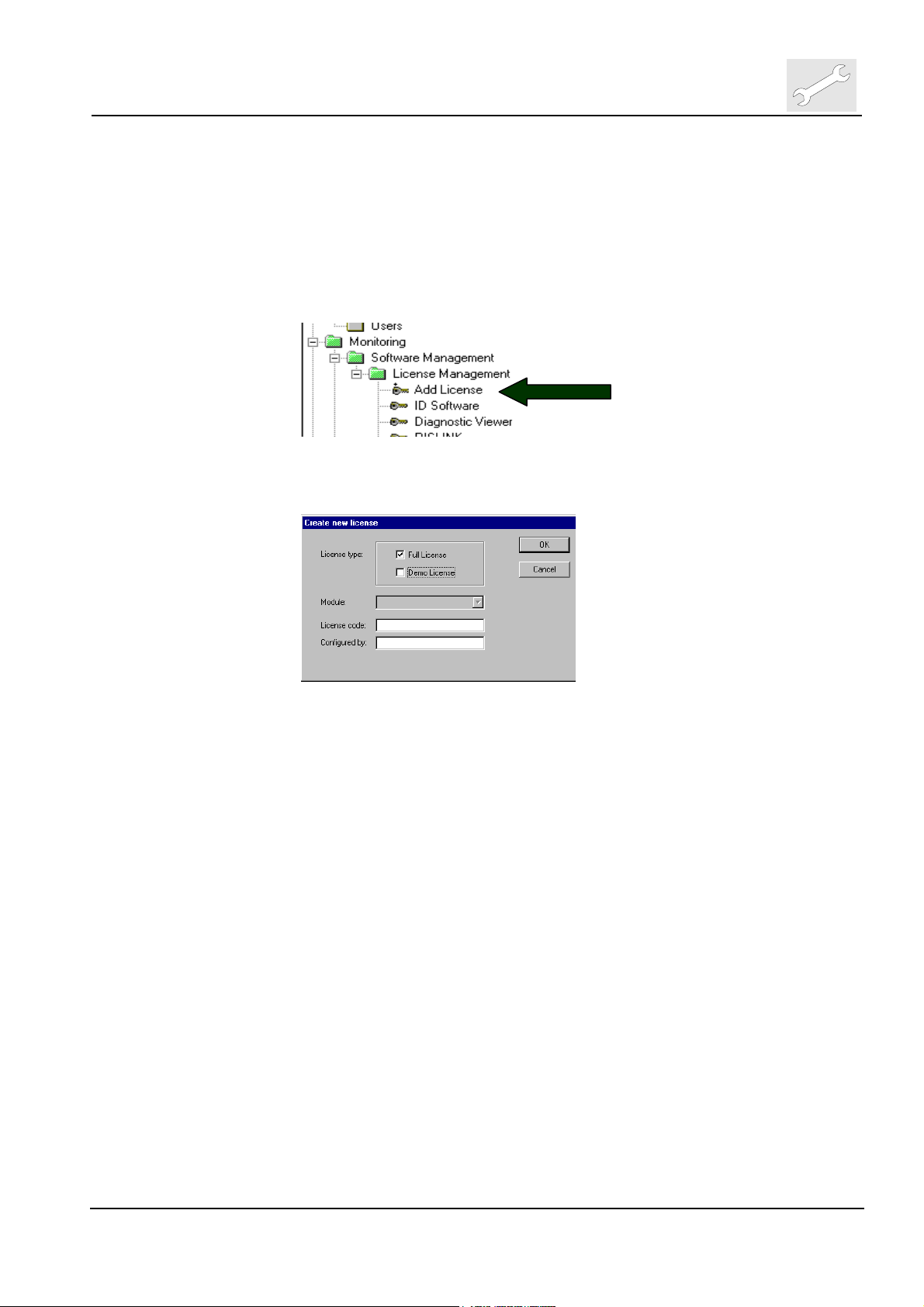
2.1 Adding Licenses
(1) To activate a licensed SW-Option select at Configuration Viewer
<Monitoring>
<Software Management>
< License Management >
(2) Double click on <Add license>
.
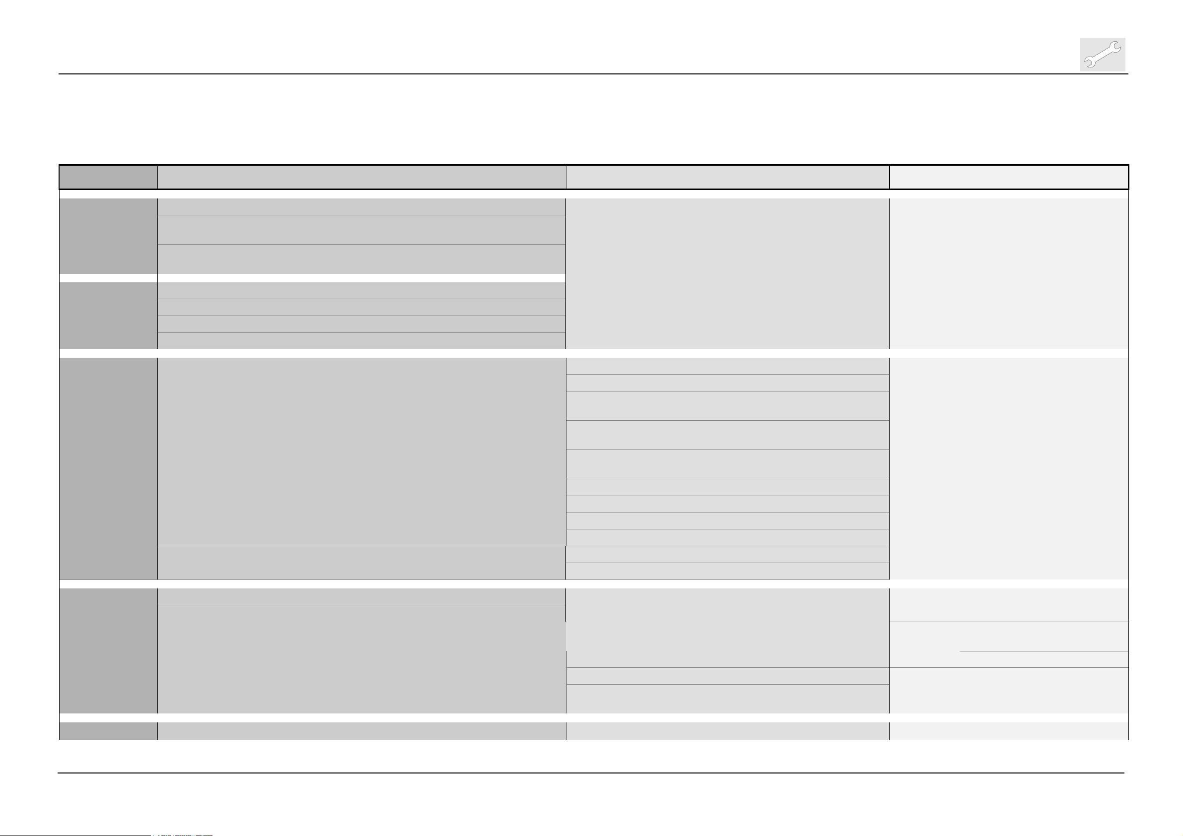
(3) The following window pops up. Select license type („Full License“ or
„Demo License “).
Repair and Service
(4) If you select “Demo License“ a list of not yet activated SW-Options
appears at “Module“. A “Demo License“ expires after 90 days (without
previous warning).
(5) If you select „Full License“ enter „License Code“ and your name. The SW-
Option is identified and activated by means of the license code.
(6) Click <OK> to finish.
Edition 1, Revision 0 ADC QS 2.1.xx Chapter 3.2 / 15
(Type 4406/421)
Page 18

Repair and Service
Machine specific tools, software tools and auxiliary equipment
3 Creation of an ADC QS Restore CD
3.1 General
The creation of a bootable Restore CD-ROM onsite makes it possible to
restore the server system at a later date back to the same identical state as it
was by creation time of the CD. Please pay attention to the following points:
• The CD must only be used on the PC where it was created!
• During the process the CD tray can open and close automatically; this
is then part of the procedure.
Together with ADC QS 2.1.xx the Restore Toolkit version 2.5 is introduced. It
provides the following new features compared with version 2.4:
• Client Restore CDs can be created as well (if CD-Writer available)
• Norton Ghost 7.5 makes it possible to directly write to the CD Writer.
This saves some time. However only high quality CD-R should be
used. Cheap ones are very error prone (esp. on Clients).
• Restore Toolkit fits on a floppy now.
• Restore CDs are date and time stamped, labeled with system type
information and which disk image is included.
• The system event logs are also included in the system disk image.
• Disk spanning is possible now (i.e. if the disk image does not fit on one
CD, it can be continued on a second one).
DD+DIS135.02E
3.2 Requirements
• ADC-QS Restore Toolkit version 2.5 or higher
• Blank or re-writeable CD (use high quality CD-Rs only)
• ADC-QS System (Server or Client) with built in CD Re-Writer
3.3 Procedure
(1) Insert the ADC QS Restore Toolkit floppy in the floppy drive.
(2) Stop ADC QS and empty the desktop Recycle bin.
Chapter 3.2 / 16 ADC QS 2.1.xx Edition 1, Revision 0
(Type 4406/421)
Page 19

DD+DIS135.02E
Repair and Service
Machine specific tools, software tools and auxiliary equipment
(3)
Re-start the system, which will boot now from floppy drive. The
following menu is shown:
Make selection according to system type:
For ADC-QS Server normally only Disk 1 needs to be restored.
For ADC-QS Client only Disk 1 exists.
(4) CD tray opens. Insert blank CD or clean re-writeable CD
(5) The following menu is shown
Enter <Y>
(6) If CD tray is not already closed, it will be closed automatically now.
(7)
Norton Ghost Software starts automatically. It reads first boot data from
floppy and starts afterwards to burn the Restore CD of the selected
Disk. No action required – takes about 12 minutes.
(8) CD tray opens automatically, when process is finished.
If the system image does not fit on a single CD, message “Insert
next media and press enter to continue…” appears. Insert
a new blank CD or clean re-writeable CD and press enter.
(9) The following window is shown:
Follow the instructions to eject the new created Restore CD and the
floppy and restart the system by pressing Ctrl+Alt+Del
Edition 1, Revision 0 ADC QS 2.1.xx Chapter 3.2 / 17
(Type 4406/421)
Page 20

Repair and Service
Machine specific tools, software tools and auxiliary equipment
(10)
Write on the new created Restore CD:
• “ADC-QS Server Restore CD”
• Date of creation
• Software version
• Creator of the CD
3.3.1 Testing the recorded Restore CD
(11) Insert the Restore CD and restart the system
(12)
The following window appears (example shows Restore CD of a client
system):
DD+DIS135.02E
Check that the image type matches your system.
Type in <q>
(For testing it is not necessary to carry out a restore procedure)
If the window does not appear, first check the boot sequence before creating
a new Restore CD.
The CD label must contain the following data:
Restore-CD for ADC-QS.2.1.xx (Server)
Hostname: <hostname>
IP-Address: <ip_address>
Created by: <Name, First Name>
Why created: <reason (e.g. upgrade)>
Creation Date: <DD:MMMM:YYYY>
Chapter 3.2 / 18 ADC QS 2.1.xx Edition 1, Revision 0
(Type 4406/421)
Page 21

DD+DIS135.02E
Repair and Service
Machine specific tools, software tools and auxiliary equipment
3.4 Restore Toolkit Version 2.5 – Potential Errors and Solutions
Most errors take place during the writing of the Ghost image, in this case an
error code is given together with a short explanation. In all cases, if an error
occurs, additional information is found in the file c:\temp\ghosterr.txt.
a) ABORT: 440, Ghost cannot run on Windows NT based systems
(NT/2K/XP).
You are attempting to use the Restore Toolkit floppy or created Restore CD
from within a Windows session.
Restart the system with the Toolkit floppy or Restore CD inserted.
b) ABORT: 52102, CD-R disc is not writeable. Insert blank media.
Ghost can only write to clean media (no multi-session possible)
Insert a new blank CD-R or an erased CD Rewritable.
c) Critical Error 0x0C Sharing Violation, Abort or Retry ?
This is a non-standard error that will normally only be seen when you are
doing some custom steps with the Ghost program. The following are known
situations:
i) The ghost image was made with a later version of Ghost (eg.
7.5) and you are trying to read it with an older version (eg.
6.01). Note: the other way around is OK (older .GHO files are
read OK by 7.5)
Use Ghost v7.5 or later.
ii) The source and destination disk are the same.
Write directly to the CD Writer.
d) ABORT:10027, Unknown image format: code 51: later Ghost version
required.
Same as c) i) above.
e) ABORT: 18190, No such file or directory (ENOENT) when opening
A:\SKIPLIST.TXT
Can not find a file referenced during the Ghost image creation process.
Leave the Restore Toolkit floppy in the drive, until everything is
complete.
f) Write protect error writing drive A (Abort, Retry, Fail?)
The write protect tab prevents the toolkit from writing some temporary files
on the floppy.
Flip the protection tab back to the write enabled position.
Edition 1, Revision 0 ADC QS 2.1.xx Chapter 3.2 / 19
(Type 4406/421)
Page 22

Repair and Service
Machine specific tools, software tools and auxiliary equipment
DD+DIS135.02E
4 Agfa DICOM bridge
See appended document AGFA DICOM Bridge Version 2.0 (User Guide)
5 ID-Viewer GUI and DICOM Modality Worklist GUI
The configuration of the ID-Viewer GUI and DICOM Modality Worklist GUI is
mainly described in the ID-Viewer User Manual.
The GUI of the ID-Viewer and the DICOM Modality Worklist can be configured
in the field only by predefined GUI templates. Screenshots of these GUI
templates can be found in chapter 11, Installation Planning. Other changes
are not foreseen in the field. If the currently provided templates should not be
accepted by the customer, inform your Global Support Center. There, a
headquarter decision will be initiated if and when a change will be provided.
6 RIS Link
The configuration of the RIS Link is described in the RIS Link Toolkit User
Manual (enclosed in the ADC QS RIS-Link Toolkit option). It gives the
information how the data provided by the RIS should look like in respect to
format, structure and DICOM mapping. The data the hospital RIS system
delivers, have to match to these definitions. Changes on ADC QS side are not
foreseen. To avoid delays during set-up it is absolutely necessary that the
customer is aware well in advance what his HIS/RIS system has to deliver.
If the customer's HIS/RIS system is not able to fulfill these requests, GSC has
to be involved right from the beginning. The goal is to have for these sites
before the actual set-up of the ADC QS starts a response from AGFA whether
these adaptation requests can be fulfilled or not.
Please note that the ADC QS RIS-Link Toolkit does not support anymore data
retrieval from RIS/HIS systems by means of a DOS executable file. Only a
Windows executable can be used. For supported connection modes refer to
ADC QS RIS-Link Toolkit user manual.
Chapter 3.2 / 20 ADC QS 2.1.xx Edition 1, Revision 0
(Type 4406/421)
Page 23
DD+DIS135.02E
Repair and Service
Machine specific tools, software tools and auxiliary equipment
7 WebAdmin
The following list gives an overview of the WebAdmin Menu Structure
1st level 2nd level Comment 3rd level Comment 4th level Comment
Show Info
Network Info
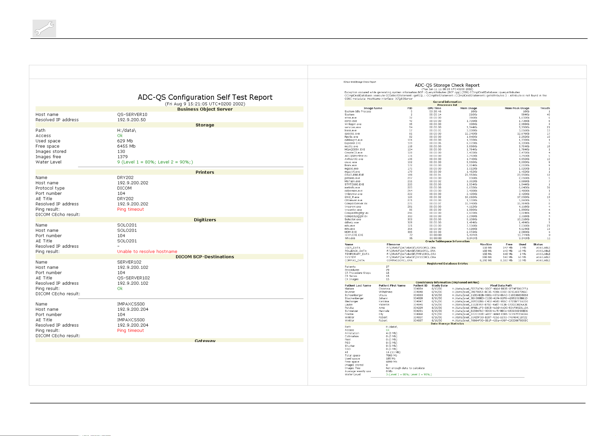
Self Test Report
Storage Check Report
Export
Event Log Files
CPF File
Compas Backup
Image File
Setup
Study settings
Devices
Specialised
Site information
Monitoring
License management
Task Manager
Quality monitoring
Documentation
Error Messages
shows network configuration info of the server
checks connection to connected devices (TCP/IP,
DICOM); see example following page.
delivers a report about storage statistics; see
example following page
view/download logfiles
view/download cpf-file
download latest Backup
view/download images/studies
shows study/exam tree
BO Server
Printers
view server settings
view, modify, add, delete ,test Printer
connections
Digitizers
view, modify, add, delete, test Digitizer
connections
Destinations
view, modify, add, delete, test Destination
connections
view, switch on/off licenses
Gateway
Printers
Digitizers
DICOM Bridge
Administration
CR Settings
view Gateway settings
synchronise printers
export partial cpf-file for Digitizer
download/view adb config files
view/edit site data screen
view exposure class list, Dicom Body part list
view Task Manager settings
Qc Tools
Dose Monitoring
BO Explorer
view Dose Monitoring Statistics
view configuration tree – do not use it for
changing !
shows QS error messages
Contrast
Spatial
view Contrast QC Phantom
results
view Spatial QC Phantom results
Edition 1, Revision 0 ADC QS 2.1.xx Chapter 3.2 / 21
(Type 4406/421)
Page 24
Repair and Service
Machine specific tools, software tools and auxiliary equipment
Example of an ADC QS Self Test Report Example of an ADC QS Storage Check Report
DD+DIS135.02E
Chapter 3.2 / 22 ADC QS 2.1.xx Edition 1, Revision 0
(Type 4406/421)
Page 25
DD+DIS135.02E
Machine specific tools, software tools and auxiliary equipment
8 Setup of a Secure User
(optional – only on Customer Request)
The “Secure User Script” allows to create a user which has very limited
access to NT-Operating System. Almost all icons are removed from the
desktop and additionally the NT-Start Menu is reduced to the absolute
minimum.
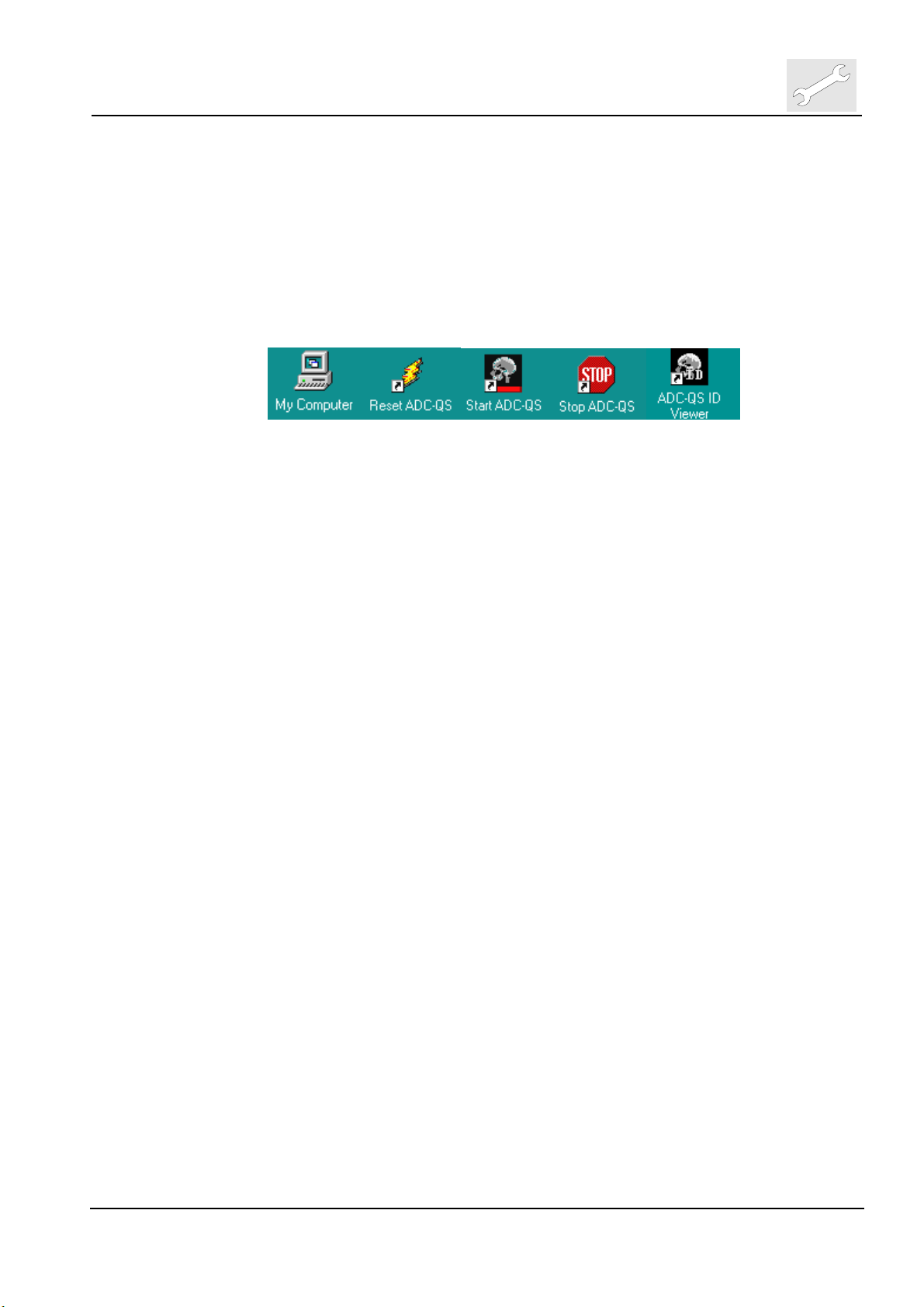
Desktop includes only the following icons:
NT-Start Menu of the Secure User is reduced to
Agfa Æ ADC QS Æ ID Viewer, Reset ADC QS, Start ADC QS, Stop ADC QS
In addition the right mouse button is deactivated on the NT-Desktop and it
prevents the user, logged in with “Secure User” account, to access the
Configuration Viewer.
However the ”Secure User” does not have any restrictions on application level.
The “Secure User” is able to delete images from the application or reject
studies. The security is only provided on NT-Operating System and
Configuration level.
The sequence of installation of the Secure User in relation to the printers is
important.
• First configure all printers on Server (with “compas” account)
• Add Secure User account on Server
• Add same Secure User account on Client. During creation of the
account the printer connections will be automatically setup as network
printers.
If you want to add a printer later on you have to perform the following steps:
• Configure printer to be added on the Server (with “compas” account)
• Remove Secure User on the Client only
• Re-install Secure User on Client again. In this way the new printer is
added to the Secure User account.
Repair and Service
8.1 Add Secure User
Only one account for a Secure User has to be created. It has to be the same
account on ADC QS Server and Client.
(1) Select
Start
AGFA
ADC-QS
Tools
Add Secure User
Edition 1, Revision 0 ADC QS 2.1.xx Chapter 3.2 / 23
(Type 4406/421)
Page 26

Repair and Service
Machine specific tools, software tools and auxiliary equipment
DD+DIS135.02E
(2) Define Secure User with a corresponding password. Confirm the
password by clicking <OK>
(3) System restarts two times. During this do not start any other application.
(4) Auto logon is switched off now. NT login window appears after every
restart.
8.2 Remove Secure User
If you want to change the complete Secure User account it is best first to
remove current Secure User and then add a new one. This has to be done
both on Server and Client.
This procedure must also be applied on the Client only, if a printer should be
added to the Secure User account (see above)
(1) Check that you are logged in as “compas"
(2) Select
Start
AGFA
ADC-QS
Tools
Remove Secure User
(3) Select Secure User, you would like to delete, from pull down menu and fill
in corresponding password. Confirm the password by clicking <OK>
(4) System restarts two times. Always login as “compas" account. If the last
Secure User has been deleted from the system, Auto Logon is activated
again.
Chapter 3.2 / 24 ADC QS 2.1.xx Edition 1, Revision 0
(Type 4406/421)
Page 27

DD+DIS135.02E
Repair and Service
Machine specific tools, software tools and auxiliary equipment
9 Installing ADC-QS into an Existing NT Domain
By default the systems delivered by AGFA are set up to operate in an
unmanaged ‘peer to peer’ network pool called ‘WORKGROUP’. This name
‘WORKGROUP’ is the same for all language versions of ADC-QS.
Further to this the ADC-QS Server and Client machines are set up with 2 local
machine accounts:
Account
Password
administrator (empty)
compas compas98
Both these accounts are members of ‘Administrator’ group on the local
machine. By default ADC-QS runs under the ‘compas’ account. The
advantage of running ADC-QS as part of ‘WORKGROUP’ is that the
administration tasks are much reduced – the downside to this is that there is
almost no security in place.
In many hospital environments ADC-QS will be used as part of a secure NT
domain. To add new ADC-QS systems to the domain will require assistance
from the local NT Domain Administrator (who has the passwords and authority
required). Follow the sequence below to add an ADC-QS Server or Client into
a domain:
9.1.1 ADC-QS System Name
Change the system name to the new name assigned by the domain
administrator – Start Menu::Settings::Control Panel::Network::Identification,
click on button ‘Change’, enter the new name, click <OK> . Click <OK> on
confirmation dialog, click <Close> on the network control panel, dialog ‘… You
must shut down and restart your computer… Restart now’, click <Yes>. The
system restarts.
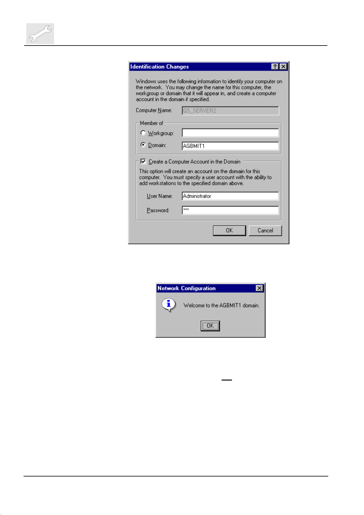
9.1.2 Add ADC-QS System to Domain
Log back in as local system Administrator (blank password ). Hold down the
shift key to defeat any auto-login. Once logged in, stop any ADC-QS autostart (Server only). From Start Menu::Settings::Control
Panel::Network::Identification, click on button ‘Change’, click on radio button
‘Domain’, enter the domain name. Select checkbox ‘Create Computer
Account in the Domain’, enter the Domain Administrator name and
password. Click <OK>.
Edition 1, Revision 0 ADC QS 2.1.xx Chapter 3.2 / 25
(Type 4406/421)
Page 28
Repair and Service
Machine specific tools, software tools and auxiliary equipment
DD+DIS135.02E
Upon success the message ‘Welcome to <Domain Name>’ will popup. Click
<OK>, then <Close>, dialog ‘… You must shut down and restart your
computer… Restart now’, click <Yes>. The system restarts.
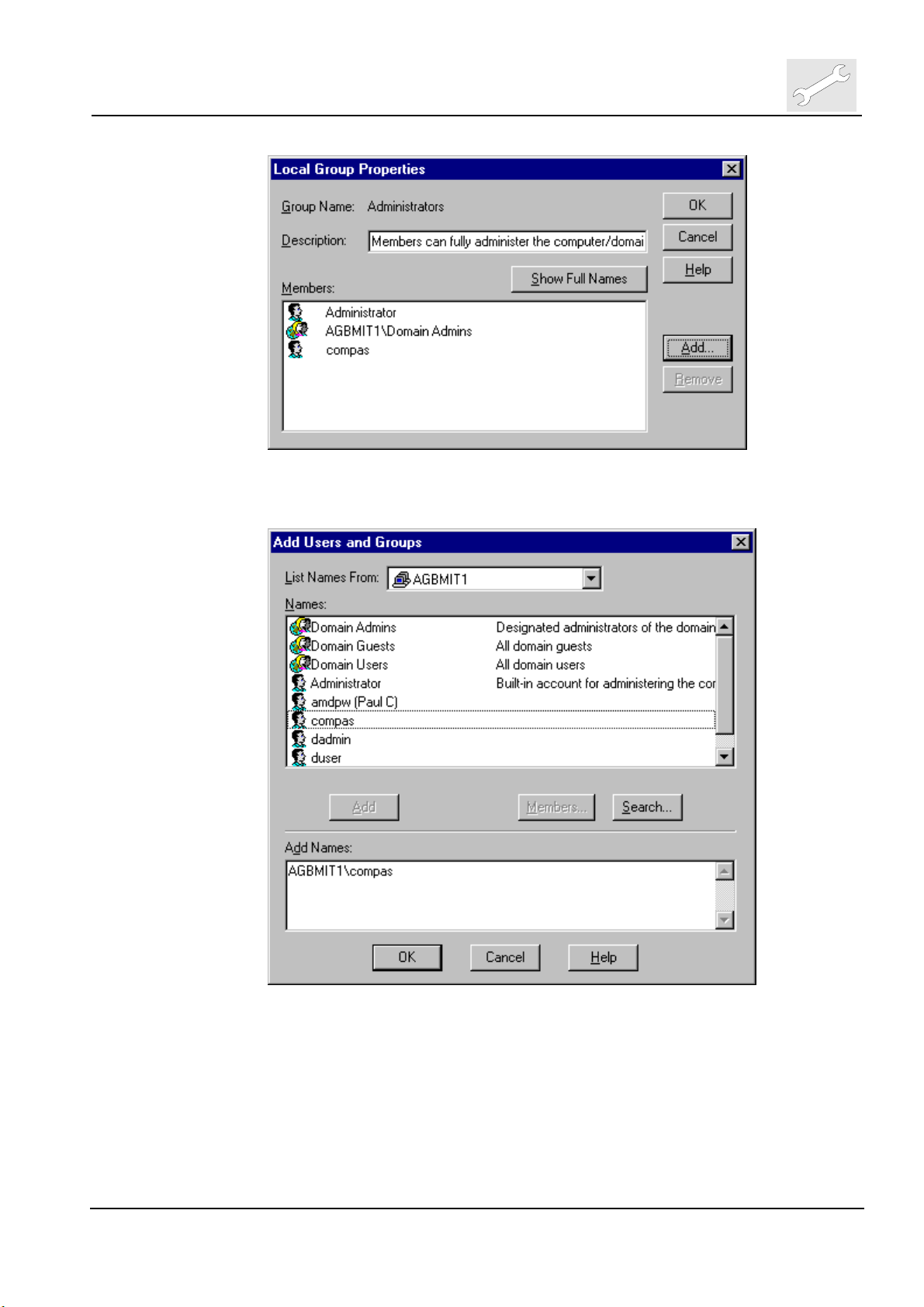
9.1.3 Adding Domain User to Local System
Log back in as local system Administrator (not
the ‘User Manager for Domains’, double click on ‘Groups->Administrators’ in
the list at the bottom half of the screen.
domain logon !). Start again
Chapter 3.2 / 26 ADC QS 2.1.xx Edition 1, Revision 0
(Type 4406/421)
Page 29
DD+DIS135.02E
Repair and Service
Machine specific tools, software tools and auxiliary equipment
Click now on ‘Add’, select compas from the Names list of the domain, click
on <Add>, the domain compas account is added to the Add Names list:
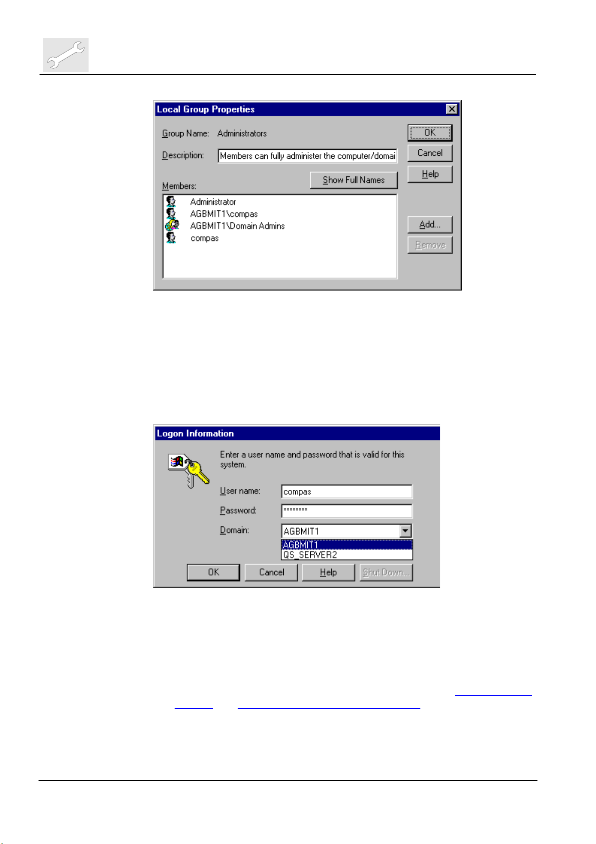
Click then on <OK> to close this dialog. The domain name\compas account
will show up in the Local Group Properties::Members list:
Edition 1, Revision 0 ADC QS 2.1.xx Chapter 3.2 / 27
(Type 4406/421)
Page 30
Repair and Service
Machine specific tools, software tools and auxiliary equipment
Click then on <OK> to close this dialog. Close the User Manager (Alt-F4, or
menu User::Exit).
DD+DIS135.02E
9.1.4 Logging onto the Domain
Log-off from the local system (‘Start Menu::Shut down::Close all programs
and log-on as different user’) ,then re-logon using the domain account as
shown below:
Once logged in, ADC-QS is now available for use.
9.1.5 Notes:
a) The auto-login and auto-shutdown feature of ADC-QS Server is still
working under domain log-in. To bypass the auto-login, hold down the
Shift key during the login phase.
b) The domain administrator will normally carry out sections Create Compas
account and Adding Domain User to Local System
you do not have to make a request for the domain administrator account
and passwords.
c) Procedures for setting up printers and other devices from the ADC-QS
Server remain the same under domain login.
Chapter 3.2 / 28 ADC QS 2.1.xx Edition 1, Revision 0
(Type 4406/421)
for you. In this way
Page 31

DD+DIS135.02E
Machine specific tools, software tools and auxiliary equipment
10 Virus Scanner Software
In the following the tested settings with McAfee virus scanners together with
ADC QS 2.1 are listed.
10.1 Settings to be changed
Internal tests were performed with the following sdat file versions for McAfee
Netshield v4.5 for Server w/Service Pack 1 (SP1), Netshield v4.5 for Client
w/SP1, and McAfeeVirus Scan NT v5.1 on ADC QS 2.1:
Server sdat4167.exe
Client sdat4167.exe
Netshield v4.5 w/SP1 Virus Scan NT v5.1
(scan engine 4.1.50 and
virus definition 4.0.4167)
sdat4184.exe
(scan engine 4.1.60 and
virus definition 4.0.4184)
(scan engine 4.1.50 and
virus definition 4.0.4167)
Repair and Service
- can not be installed on server -
sdat4184.exe
(scan engine 4.1.60 and
virus definition 4.0.4184)
Netshield v4.5 w/SP1 for Server and Netshield v4.5 w/SP1 for Client are two
separate software packages.
If a virus scanner is supposed to be installed on an ADC QS 2.1, AGFA
recommends to use the above mentioned versions of McAfee virus scanners
with the below mentioned settings.
This configuration did not show a noticeable impact on ADC QS 2.1 in our test
environment. For any other configuration or virus scan software AGFA cannot
make a statement and it may have impact on the proper operating of
ADC QS 2.1.
10.1.1 Settings deviating from default
The following settings have to be changed from default to the shown status
when installing McAfee on ADC QS 2.1:
10.1.1.1 NetShield v4.5 for Server w/SP1
Changes to settings are tested for sdat4167.exe and sdat4184.exe.
DETECTION TAB
Scan Section
Outbound files UNCHECKED
Files to Scan Section
Selected file types and for known
macro viruses in all files
Selected File Types Only CHECKED
UNCHECKED
Edition 1, Revision 0 ADC QS 2.1.xx Chapter 3.2 / 29
(Type 4406/421)
Page 32

Repair and Service
Machine specific tools, software tools and auxiliary equipment
ACTIONS TAB
REPORTS TAB
Response to User Section
Send messages to users CHECKED
Log File Section
Limit size of log to [100KB] CHECKED
10.1.1.2 NetShield v4.5 for Client w/SP1
Changes to settings are tested for sdat4167.exe.
DETECTION TAB
REPORT TAB
EXCLUSIONS TAB
Scan Section
Outbound Files UNCHECKED
Advanced Section
Enabled heuristics scanning CHECKED
Enable macro heuristics scanning CHECKED
What to Log Section
Session Settings UNCHECKED
Item
\Recycled REMOVE
DD+DIS135.02E
10.1.1.3 Virus Scan NT v5.1 for Client
Virus Scan NT v5.1 can only be installed on NT-workstation operating system.
Changes to settings are tested for sdat4184.exe.
DETECTION TAB
Scan Section
Outbound Files UNCHECKED
Advanced Section
Enabled heuristics scanning CHECKED
Enable macro heuristics scanning CHECKED
Chapter 3.2 / 30 ADC QS 2.1.xx Edition 1, Revision 0
(Type 4406/421)
Page 33

DD+DIS135.02E
Machine specific tools, software tools and auxiliary equipment
10.2 Overview of all Settings
10.2.1 NetShield v4.5 for Server w/SP1
Repair and Service
Scan Engine Version:
Virus Definition
Version:
sdat file:
DETECTION
TAB
ADVANCED
TAB
ACTIONS TAB
REPORTS
TAB
Scan Section
Inbound files CHECKED
Outbound files
Network Drives UNCHECKED
Boot Sector(s) CHECKED
Floppy during shutdown CHECKED
Files to Scan Section
All files UNCHECKED
Selected file types and for known
macro viruses in all files
Selected File Types Only CHECKED
File Types DEFAULT SETTINGS
Heuristics Section
Find unknown program viruses UNCHECKED
Find unknown micro viruses CHECKED
Compressed Files Section
Scan compressed files (e.g. PkLite) UNCHECKED
Scan files in archives (e.g. ZIP) UNCHECKED
General Section
Enable File Scan caching
Enable on-access scanning at system
startup CHECKED
When Virus is Found Section
Dropdown Selection Clean infected files
Response to User Section
Send messages to users UNCHECKED
Disconnect remote users and deny
access to network share
Log File Section
Log to file CHECKED
Log file location C:\Program Files\Network
Limit size of log to [100KB]
What to Log Section
4.1.60
4.0.4184
sdat4184.exe
UNCHECKED
UNCHECKED
CHECKED
automatically
UNCHECKED
Associates\
NetShield2000\ NetShield
ActivityLog.txt
CHECKED
Edition 1, Revision 0 ADC QS 2.1.xx Chapter 3.2 / 31
(Type 4406/421)
Page 34

Repair and Service
Machine specific tools, software tools and auxiliary equipment
Virus Detection CHECKED
Virus Cleaning CHECKED
Infected File Deletion GREYED-OUT
Infected File Move GREYED-OUT
Session Settings UNCHECKED
Sessions Summary CHECKED
Date and Time CHECKED
User Name CHECKED
EXCLUSIONS
TAB
Item none
10.2.2 NetShield v4.5 for Client w/SP1
Scan Engine Version:
Virus Definition Version:
sdat file:
4.1.50
4.0.4167
sdat4167.exe
DETECTION
TAB
ACTION TAB
ALERT TAB
Enable System Scan CHECKED
Scan Section
Inbound files CHECKED
Outbound files
Floppies on Access CHECKED
Floppy on Shutdown CHECKED
What to Scan Section
All files UNCHECKED
Program Files Only CHECKED
Extensions DEFAULT SETTINGS
Compressed Files CHECKED
Network Files UNCHECKED
General Section
System scan can be disabled
Show icon in taskbar
Advanced Section
Enabled heuristics scanning
Enabled macro heuristics scanning
When Virus is Found Section
Dropdown Selection “Prompt user for action”
Possible Actions Section
Clean file CHECKED
Delete file CHECKED
Move file CHECKED
Stop Access CHECKED
Exclude File CHECKED
Network Alert Section
DD+DIS135.02E
UNCHECKED
CHECKED
CHECKED
CHECKED
CHECKED
Chapter 3.2 / 32 ADC QS 2.1.xx Edition 1, Revision 0
(Type 4406/421)
Page 35

DD+DIS135.02E
REPORT TAB
EXCLUSIONS
TAB
EMAIL SCAN
DOWNLOAD
SCAN
INTERNET
FILTER
SECURITY
Repair and Service
Machine specific tools, software tools and auxiliary equipment
Notify Alert Manager UNCHECKED
If ‘Prompt for action’ is selected
Section
Display custom message UNCHECKED
Sound audible alert CHECKED
Log File Section
Log to file CHECKED
Limit size of log file to “100”
kilobytes
What to Log Section
Virus Detection CHECKED
Virus Cleaning CHECKED
Infected File Deletion CHECKED
Infected File Move CHECKED
Session Settings
Sessions Summary CHECKED
Date and Time CHECKED
User Name CHECKED
Item
\Recycled
Enable Scanning of Email
Attachments
Enable Internet Download Scanning UNCHECKED
Enable Java & Active X Filter UNCHECKED
Enable Password Protection UNCHECKED
UNCHECKED
UNCHECKED
CHECKED
REMOVE
Edition 1, Revision 0 ADC QS 2.1.xx Chapter 3.2 / 33
(Type 4406/421)
Page 36

Repair and Service
Machine specific tools, software tools and auxiliary equipment
10.2.3 Virus Scan NT v5.1 for Client
Scan Engine Version:
Virus Definition Version:
sdat file:
DETECTION
TAB
ACTION TAB
ALERT TAB
REPORT TAB
Enable System Scan CHECKED
Scan Section
Inbound files CHECKED
Outbound files
Floppies on Access CHECKED
Floppy on Shutdown CHECKED
What to Scan Section
All files UNCHECKED
Program Files Only CHECKED
Extensions DEFAULT SETTINGS
Compressed Files CHECKED
Network Files UNCHECKED
General Section
System scan can be disabled
Show icon in taskbar
Advanced Section
Enabled heuristics scanning
Enabled macro heuristics scanning
When Virus is Found Section
Dropdown Selection “Prompt user for action”
Possible Actions Section
Clean file CHECKED
Delete file CHECKED
Move file CHECKED
Stop Access CHECKED
Exclude File CHECKED
Network Alert Section
Notify Alert Manager UNCHECKED
If ‘Prompt for action’ is selected
Section
Display custom message UNCHECKED
Sound audible alert CHECKED
Log File Section
Log to file CHECKED
Limit size of log file to “100” kilobytes CHECKED
What to Log Section
Virus Detection CHECKED
Virus Cleaning CHECKED
Infected File Deletion CHECKED
4.1.60
4.0.4184
sdat4184.exe
DD+DIS135.02E
UNCHECKED
CHECKED
CHECKED
CHECKED
CHECKED
Chapter 3.2 / 34 ADC QS 2.1.xx Edition 1, Revision 0
(Type 4406/421)
Page 37

DD+DIS135.02E
EXCLUSIONS
TAB
EMAIL SCAN
DOWNLOAD
SCAN
INTERNET
FILTER
SECURITY
Repair and Service
Machine specific tools, software tools and auxiliary equipment
Infected File Move CHECKED
Session Settings CHECKED
Sessions Summary CHECKED
Date and Time CHECKED
User Name CHECKED
Item
\Recycled REMOVE
Enable Scanning of Email
Attachments
Enable Internet Download Scanning UNCHECKED
Enable Java & Active X Filter UNCHECKED
Enable Password Protection UNCHECKED
UNCHECKED
Edition 1, Revision 0 ADC QS 2.1.xx Chapter 3.2 / 35
(Type 4406/421)
Page 38

Agfa Healthcare - Agfa DICOM Bridge User Guide, v2.0b, Date: 16-May-2002 Page 1 of 32
A
A
GFA
H
EALTHCARE
Connectivity Documentation
AGFA DICOM Bridge
(ADB) – Version 2.0b
User Guide
16 May 2002
gfa Healthcare Document No. 000xxx, Revision 2.0b
Copyright © 1998 - 2002 Agfa Heathcare
All rights reserved.
Page 39

Page 2 of 32 Agfa Healthcare - Agfa DICOM Bridge User Guide, v2.0b, Date: 16-May-2002
Table of Contents
1. INTRODUCTION ................................................................................................................. .........................................5
1.1 G
1.2 D
1.3 R
ENERAL
EFINITIONS
EFERENCES
...................................................................................................................................................................5
/ A
BBREVIATIONS
.................................................................................................................................5
..............................................................................................................................................................5
2. ABOUT THE DICOM BRIDGE...................................................................................................................................6
2.1 G
2.2 M
2.3 O
2.4 D
ENERAL
ESSAGE PASSING
VERVIEW OF DATASET PROCESSING
ATABASE FILE
...................................................................................................................................................................6
....................................................................................................................................................8
.......................................................................................................................................................11
........................................................................................................................9
2.4.1 Database Records...........................................................................................................................................11
2.4.2 Example Database File...................................................................................................................................11
2.5 L
IMITATIONS ON USE
...............................................................................................................................................13
3. CONFIGURATION .....................................................................................................................................................14
3.1 C
3.2 D
3.3 D
3.4 D
3.5 M
3.6 P
3.7 L
3.8 M
3.9 I
3.10 R
3.11 A
3.12 U
3.13 M
3.14 R
3.15 A
ONNECTION(S
EFINITION FILE(S
ATABASE SIZE
ATASET DECODING
APPING
LACEHOLDER CHARACTER
OGGING
ATCHING ATTRIBUTES
DENTICAL ATTRIBUTES
EMOVE ATTRIBUTES
DD ATTRIBUTES
PDATE ATTRIBUTES
APPED ATTRIBUTES
EDIRECT ASSOCIATION ATTRIBUTES
TTRIBUTE VALUE KEYWORDS
).......................................................................................................................................................14
)..................................................................................................................................................14
.......................................................................................................................................................15
...............................................................................................................................................15
/ U
PDATE ORDERING
................................................................................................................................15
....................................................................................................................................15
.................................................................................................................................................................16
..........................................................................................................................................16
...........................................................................................................................................17
..............................................................................................................................................17
....................................................................................................................................................18
..............................................................................................................................................18
..............................................................................................................................................18
...............................................................................................................................20
.....................................................................................................................19
3.15.1 $DATE Keyword.............................................................................................................................................20
3.15.2 $TIME Keyword..............................................................................................................................................20
3.15.3 $INCREMENT Keyword.................................................................................................................................20
3.15.4 $MATCH_COUNT Keyword..........................................................................................................................20
3.15.5 $REMOVE_COMPONET_GROUPS Keyword..............................................................................................21
3.15.6 $CONVERT_EXTENDED_CHARS Keyword.................................................................................................21
3.15.7 $REMOVE_EXTENDED_CHARS Keyword ..................................................................................................21
3.15.8 $CHANGE_ENCODING(set) Keyword..........................................................................................................21
4. WORKING WITH THE DICOM BRIDGE..............................................................................................................22
4.1 G
4.2 W
ENERAL
INDOWS GRAPHICAL USER INTERFACE
.................................................................................................................................................................22
................................................................................................................22
4.2.1 Main menu options .........................................................................................................................................22
4.2.2 Configure Dialog............................................................................................................................................23
4.2.3 Connection Dialog..........................................................................................................................................24
4.2.4 Attribute Matching Dialog..............................................................................................................................25
4.2.5 Identical Attributes Dialog .............................................................................................................................25
4.2.6 Attribute Removal Dialog...............................................................................................................................25
4.2.7 Add Attributes Dialog.....................................................................................................................................26
4.2.8 Update Attributes Dialog................................................................................................................................26
4.2.9 Attribute Value Dialog....................................................................................................................................27
4.2.10 Map Attributes Dialog....................................................................................................................................27
4.2.11 Attribute Redirect Association Dialog............................................................................................................28
Copyright © 1998 - 2002 Agfa Medical Division.
All rights reserved.
Page 40

Agfa Healthcare - Agfa DICOM Bridge User Guide, v2.0b, Date: 16-May-2002 Page 3 of 32
4.3 W
4.4 W
ORKING WITH MULTI-BYTE AND SPECIAL CHARACTERS
ORKING WITH PRIVATE ATTRIBUTES
................................................................................................................... 29
...................................................................................... 29
5. INSTALLATION......................................................................................................................................................... 30
5.1 G
5.2 W
ENERAL
INDOWS
................................................................................................................................................................ 30
(NT) ....................................................................................................................................................... 30
5.2.1 Upgrading from a Previous Version .............................................................................................................. 30
5.2.2 Installing ADB................................................................................................................................................ 30
5.2.3 Starting the ADB NT Service.......................................................................................................................... 30
6. CONFIGURATION OF ADB ON ADC QS .............................................................................................................. 32
Copyright © 1998 - 2002 Agfa Heathcare
All rights reserved.
Page 41

Page 4 of 32 Agfa Healthcare - Agfa DICOM Bridge User Guide, v2.0b, Date: 16-May-2002
Revision History
Version Date Description
1.0 31 July 1998 Initial draft – AGFA DICOM Bridge is the new name for the
ADC Filter program.
1.1 11 September 1998 Added support for keywords $DATE, $TIME and
$INCREMENT.
1.2 23 November 1998 Added support for the DICOM Verification Service Class.
Corrected the handling of zero-length attribute values in
the database records.
1.3 10 January 1999 Various bug-fixes.
1.4 29 March 1999 Multi-threading support. Multiple input/output combinations
can share the database records. A maximum of 20
connections can be made simultaneously.
1.5 17 May 1999 Added description of Windows GUI.
1.6 8 November 1999 Updated GUI after review by users.
1.7 12 October 2000 Bug-fix to ensure that all values associated with mapped
attributes are copied to the destination attribute. In earlier
versions, only the first attribute value was copied.
1.8 20 February 2001 Updated Windows installation procedure to use
InstallShield.
Added maximum logfile size. Logfile is truncated once the
maximum size is reached (LOGFILE-SIZE).
Added adbservice.exe – to run as NT service on Windows
NT platform.
1.9 15 March 2001 Added Socket Server to allow concurrent connections to
same TCP/IP port. Socket Server spawns a new thread for
each managed connection.
Added MSVCP60.DLL to InstallShield release.
1.9a 16 May 2001 Upgrades to documentation to address SCR #s 9105,
9101, 9096, 9094, 9085, 9084, 9083, 9077, 9073
1.9b 21 May 2001 Minor changes for NT commercial version
1.9d 21 June 2001 Updated Solaris install procedure. Added Unix tool
documentation. Updated Table of Contents.
2.0a 15 May 2002 Added support for redirecting associations and support for
Asian languages. Added the keywords
$REMOVE_COMPONENT_GROUPS,
$CONVERT_EXTENDED_CHARS,
$REMOVE_EXTENDED_CHARS,
$CHANGE_ENCODING and $MATCH_COUNT.
Changed order of mapping and update. Removed the
Windows command line version. Added sections to
Chapter 2. Removed the Solaris information. General
enhancements to the document.
Copyright © 1998 - 2002 Agfa Medical Division.
All rights reserved.
Page 42

Agfa Medical Division - Agfa DICOM Bridge User Guide, v2.0b, Date: 16-May-2002 Page 5 of 32
1. Introduction
1.1 General
The AGFA DICOM Bridge is a simple device, inserted between a DICOM Storage SCU and a SCP, that can be used to
modify the attributes in the messages passed between the SCU and SCP. It can be used to provide temporary
solutions to connectivity problems.
ADB is intended to be used as a temporary connectivity tool – i.e, a tool to provide a temporary fix to DICOM
messages between two devices so that a connection can be achieved. ADB should only be used until the
cause of the connectivity prob lem has been solved (eit her in the SCU o r SCP). Great care must b e taken wh en
installing ADB to ensure that the SCU & SCP vendors and the site are aware that changes are being made to
the messages.
In the first versions of ADB, only the DICOM Image Service Classes are supported.
At the time of this writing, version 2.0 of ADB is only supported on the Windows platform . Us e the lates t 1.x ver s ion f or
Solaris. The database files created by this version can not be used with 1.x versions of ADB.
1.2 Definitions / Abbreviations
The following Definitions and Abbreviations are used throughout this document:
ADB AGFA DICOM Bridge.
ADVT AGFA DICOM Validation Tool.
ASCII A 127 character character set that has non-printable control characters, the 26 English
characters (both upper and lower case), roman numbers and some punctuation marks.
Database file File that contains the configuration information for ADB and the saved database records.
Database record The set of attributes that are saved for each Matching Dataset.
Dataset The data in a DICOM C-Store Request. This is the data that makes up a DICOM image.
DICOM Digital Imaging and Communication in Medicine.
Keyword A value used in the configuration of ADB that will change the attribute at runtime. Keywords
are started with a ‘$’.
Macro keyword A keyword that provides a value for an attribute.
Matched Record The database record that, for each of the attributes in the Matching Attributes, has attribute
values that are the same as the attribute values in the Matching Dataset.
Matching Dataset A dataset that matches all of the Matching Attributes. Only Matching Datasets will be
processed by ADB.
Operation keyword A keyword that performs an operation on an attribute value.
1.3 References
[1] ACR/NEMA Standards Publications, No PS3, 2001
DICOM Standards Part 1 - Introduction,
Part 2 - Conformance,
Part 3 - Information Object Definitions,
Part 4 - Service Class Specifications,
Part 5 - Data Structures and Encoding,
Part 6 - Data Dictionary,
Part 7 - Message Exchange,
Part 8 - Network Communication Support,
Part 9 - Point to Point Communication Support for Message Exchange,
Part 10 - Media Storage and File Format for Media Interchange,
Part 11 - Media Storage Application Profiles,
Part 12 - Media Formats and Physical Media for Media Interchange,
Part 13 - Print Management Point-to-Point Communication Support,
& various supporting Supplements.
Copyright © 1998 - 2002 Agfa Heathcare
All rights reserved.
Page 43

Page 6 of 32 Agfa Healthcare - Agfa DICOM Bridge User Guide, v2.0b, Date: 16-May-2002
2. About the DICOM Bridge
2.1 General
The AGFA DICOM Bridge program is used between a DICOM Source SCU and Destination SCP. Initially only the
DICOM Image Storage Service Classes are supported.
A
Source
SCU
localhost
DICOM
Bridge
B
Destination
SCP
The DICOM Bridge can either be installed together with the Source SCU on the host computer (see above) or on a
standalone computer (see below).
A
Source
SCU
In the standard connection between Source SCU and Destination SCP, the SCU will mak e a connection with the SCP
directly and exchange DICOM messages (s ee paths A above). When the DICO M Bridge is used, the Sourc e SCU firs t
makes a connec tion with the DICOM Bridge (as SCP) , which in turn makes a connection (as SCU) with the Destination
SCP (see paths B above).
The DICOM Bridge imm ediately passes the received message on to the SCU or SCP. Some m essages are passed
transparently (DICOM Bridge does not interpret them), other mes sages are interpr eted by the DICOM Bridge and m ay
be modified en-route.
DICOM
Bridge
B
Destination
SCP
Copyright © 1998 - 2002 Agfa Medical Division.
All rights reserved.
Page 44

Agfa Medical Division - Agfa DICOM Bridge User Guide, v2.0b, Date: 16-May-2002 Page 7 of 32
A more detailed overview diagram showing typical ADB communication is as follows:
Machine A Machine B
IP Address:
99.100.100.5
IP Address:
99.100.100.8
ADB:
Source
Software:
ADC-QS
VIPS
AE_TITLE:
QS1
Passed Unchanged
or
Modi fied E n-rout e
Listening Port:
5044
Destination
Software:
IMPAX
Archive
AE_TITLE:
WKS1
Listening Port:
58002
The diagram above shows that ADB is part of the s our ce machine and while this is typical, it is not a requir ement. ADB
can run on a third networked box. The im por tant point to rem em ber is that the CPF f ile used to define the network and
DICOM configurations must know the IP address of the box where ADB is running and the listening port ADB is
configured to use. ADB mus t then also be configured to know the IP addres s of the destination machine and the port
number that the destination software is listening on. (See section 3.1, “Connection(s)” in the Configuration chapter
below.)
For ADB, a valid CONNECTION line in the database.txt file for the above situation would be:
CONNECTION “5044:99.100.100.8:58002”
Notice that Machine A’s IP address is not used anywhere in ADB. The location of ADB as seen by Machine A’s
software (ADC-QS, VIPS) is configured in the CPF file.
From ADB v1.4 on, multiple source and destination combinations can be defined which will share the same set of
Database Records.
Copyright © 1998 - 2002 Agfa Heathcare
All rights reserved.
Page 45

Page 8 of 32 Agfa Healthcare - Agfa DICOM Bridge User Guide, v2.0b, Date: 16-May-2002
2.2 Message Passing
The message passing for the storage of a single image during an Association is as follows:
Source SCU DICOM Bridge Destination SCP
- wait for Connection/Association
- wait for Connection/Association
- connect to DICOM Bridge ->
- connect to Destination SCP ->
- send Associate Request ->
- send Associate Request ->
- handle Associate Request
<- return Associate Accept
- process Associate Accept
<- return Associate Accept
- send C-STORE-RQ Command ->
- queue C-STORE-RQ Command
- send first Image Dataset PDU ->
- decode Image Dataset PDU
- perform attribute matching and
modification
- encode new Image Dataset PDU(s)
if association redirect
- send Release Request ->
- receive Release Request
<- return Release Response
- receive Release Response
- close connection with original SCP
- original SCP waits for next
Connection/Association
- connect to redirect SCP
- create new Associate Request
- send new Associate Request to
redirect SCP ->
- redirect SCP handles Associate
Request
<- return Associate Accept
- the redirect SCP now handles
the rest of the transactions
- receive Associate Accept
- send queued C-STORE-RQ
Command ->
- receive C-STORE-RQ
- send modified Image Dataset
PDU(s) ->
- receive first Image Dataset
PDU(s)
- send remaining Image Dataset
PDU(s) ->
- send remaining Image Dataset
PDU(s) ->
- receive remaining Image
Dataset PDU(s)
- handle Image
<- return C-STORE-RSP
<- return C-STORE-RSP
- receive C-STORE-RSP
- send Release Request ->
Copyright © 1998 - 2002 Agfa Medical Division.
All rights reserved.
Page 46

Agfa Medical Division - Agfa DICOM Bridge User Guide, v2.0b, Date: 16-May-2002 Page 9 of 32
Source SCU DICOM Bridge Destination SCP
- send Release Request ->
- receive Release Request
<- return Release Response
- wait for next
Connection/Association
<- return Release Response
- wait for next Connection/Association
- receive Release Response
- make next connection to DICOM
Bridge…
NOTE: Only the first Image Dataset PDU is decoded. It is assumed that the first PDU will normally contain most
demographic data (certainly true if PDU size is about 16k B). But the demographic data must be sent in a single PDU.
Further enhancements to ADB will be required if this is not the case.
2.3 Overview of Dataset Processing
When a Datas et is received, the f irst PDU is decoded and then proc essed. T he processed datas et is re-encoded and
sent to the SCP. The remainder of the PDUs in the received dataset are then forwarded to the SCP without any
processing. This section gives an overview of how the processing is done.
The first step of the pr ocessing is to determ ine if the dataset should be pr ocessed. T his is done using the Matching
Attributes defined in the database file. If each of the attributes that are in the Matching Attributes m atch the attributes
in the dataset, then the dataset is a Matching Dataset and the dataset will be further processed. If the datas et does not
match all of the Matching Attributes , then the dataset will not be proces sed by ADB and it will be for warded to the SCP
without any modification.
The next step in processing is to c heck to see if there is a database rec or d that matches the Matching Dataset. This is
done by going through each database record and comparing the values f or each of the attributes that are lis ted in the
Matching Attributes. If the values in the Matching Dataset and the database r ecord are the same, then the databas e
record is used as the Matched Record. If there is no Matched Record, then a new database recor d is created using
the data in the Matching Dataset.
If there is a Matched Record, then the Matching Dataset is updated to set all of the attributes that are in the Identical
Attributes in the database file to the values that are stored in the Matched Record.
For all Matching Datasets, all attributes that are in the Remove Attributes in the database file are then removed from
the dataset. All attributes that are in the Add Attributes in the database file will be added to the Matching Datas et, if
the attribute in the dataset does not already have a non-zero value.
The attributes in the Mapped Attributes in the database file will be copied from the specif ied attribute in the Matching
Dataset to the specified attribute in the Matching Dataset. Then the attributes in the Update Attributes in the
database file will be updated in the Matching Dataset as specif ied, but only if the dataset already includes the attribute.
In versions of ADB prior to v2.0, the Update occur s before the Mapping. Database files that are upgraded to v2.0 or
above will maintain that ordering. New database files will be created with the ordering specified here.
The Redirect Association Attributes in the database file are c heck ed to see if the assoc iation should be redirec ted. If
each of the attributes that are in the Redirect Association Attributes match the attributes in the Matching Dataset, then
the association will be redirected as specified. If any of the attributes do not match, or if there are no Redirect
Association Attributes, then the association will not be redirected.
The modified Matching Dataset is then re-encoded and sent to the appropriate SCP.
When the association is closed, any changes to the database records are written out to the database file.
Copyright © 1998 - 2002 Agfa Heathcare
All rights reserved.
Page 47

Page 10 of 32 Agfa Healthcare - Agfa DICOM Bridge User Guide, v2.0b, Date: 16-May-2002
t
M
R
The following diagram shows the flow of the dataset processing.
SCU sends Dataset
ADB receives
Datase
no matching record found
Create New Database
Record
Compare with
Matching Attributes
Have a
atching Dataset
Compare with Database
Found a Matching
ecord
Update Identical
Attributes
Remove Remove Attributes
Add Add Attributes
does not match
Map Mapped Attributes
Remove Remove Attributes
Update Update Attributes
Check Redirect Association Attributes to
see if the association should be redirected
Send Dataset to SCP
Copyright © 1998 - 2002 Agfa Medical Division.
All rights reserved.
Page 48

Agfa Medical Division - Agfa DICOM Bridge User Guide, v2.0b, Date: 16-May-2002 Page 11 of 32
2.4 Database File
The database file stores the c onfiguration inf orm ation f or the ADB and the s tored database rec ords. T he c onfiguration
information is norm ally modified using the W indows Graphical Us er Interface (G UI) version of ADB. See s ection 4.2,
“Windows G raphical User Interface”, for inform ation on the use of the GUI to configure ADB. The def initions of the
configuration parameters are given in section 3, “Configuration”.
2.4.1 Database Records
A received dataset that matches the attr ibutes in the Matching Attributes is called a Matching Dataset. Each tim e a
Matching Dataset is received, the database records are checked to see if there is a record that has the same values for
each of the attributes in the Matching Attributes as the Matc hing Dataset has. If ther e is none, then a new database
record is created based on the Matching Dataset. The inform ation that is stor ed is used f or proc essing f uture datasets
that match this record. The record is made up of all of the attributes in the Matching, Identical and Redirect Association
Attributes and all $INCREMENT and $MATCH_COUNT attributes. The number of database records stored is
configurable and generally should be set to the maximum number of images processed in a day at the site.
2.4.2 Example Database File
The following is an example of the ASCII text based database file. (A file of 100 records will be approximately 50kB.)
DATABASE-CONTENTS
CONNECTION "1024:localhost:1030"
DEFINITION "sc-img.def"
MAXIMUM-RECORDS 100
LAST-GROUP-TO-DECODE 0x0020
MAP-BEFORE-UPDATE true
PLACEHOLDER-CHARACTER "_"
LOGGING standard
LOG-TO-FILE false
LOGFILE-SIZE 5
MATCHING-ATTRIBUTES
(0x00100010, PN) # Patient’s Name
(0x00100020, LO) # Patient ID
(0x00080020, DA) # Study Date
(0x00081030, LO) # Study Description
(0x0008103E, LO) # Series Description
(0x00080070, LO) # Manufacturer
(0x00081010, SH) # Station Name
END-MATCHING-ATTRIBUTES
IDENTICAL-ATTRIBUTES
(0x0020000D, UI) # Study Instance UID
(0x0020000E, UI) # Series Instance UID
END-IDENTICAL-ATTRIBUTES
REMOVE-ATTRIBUTES
END-REMOVE-ATTRIBUTES
ADD-ATTRIBUTES
(0x00080021, DA, "$DATE") # Series Date
END-ADD-ATTRIBUTES
UPDATE-ATTRIBUTES
(0x00080030, TM, "$TIME") # Study Time
(0x00200013, IS, "$INCREMENT") # Image Number
Copyright © 1998 - 2002 Agfa Heathcare
All rights reserved.
Page 49

Page 12 of 32 Agfa Healthcare - Agfa DICOM Bridge User Guide, v2.0b, Date: 16-May-2002
END-UPDATE-ATTRIBUTES
MAPPED-ATTRIBUTES
(0x00081030, LO) # Study Description
(0x00180015, CS) # Body Part Examined
END-MAPPED-ATTRIBUTES
REDIRECT-ASSOCIATION "::"
END-REDIRECT-ASSOCIATION
DATABASE-RECORD 1
(0x00100010, PN, "First^Patient") # Patient’s Name
(0x00100020, LO, "SC-I1") # Patient ID
(0x00080020, DA, "19970917") # Study Date
(0x00081030, LO, "Study Description") # Study Description
(0x0008103E, LO, "Series Description") # Series Description
(0x00080070, LO, "Manufacturer") # Manufacturer
(0x00081010, SH, "StationName") # Station Name
(0x0020000D, UI, "7.0") # Study Instance UID
(0x0020000E, UI, "7.0.1") # Series Instance UID
(0x00200013, IS, "2") # Image Number
END-DATABASE-RECORD
END-DATABASE-CONTENTS
ADB will test every image received ( the rec eived dataset) to s ee if it contains the attributes for Patient’s Name, Patient
ID, Study Date, Study Description, Series Description, Manuf acturer and Station Name. If it does not, no proces sing
will be done on the image and the image will be sent to the Destination SCP unchanged. The ADB database will not be
modified. If the im age does have all of the attributes, the image matched the Matching Attributes and will be further
processed and is called the Matching Dataset.
For a Matching Dataset, the ADB will then look for a recor d in the database that has the sam e Patient’s Nam e, Patient
ID, Study Date, Study Description, Series Description, Manufacturer and Station Name. If a record is found in the
database that has all of these attributes the same as the attributes in the Matching Dataset, then a Matched Recor d
has been found.
If a Matched Record is found, the r ec eived image’s Study Instance UID and Series Instanc e UID will be modified to the
database values. The Series Date will be set to today’s date and added. The Study Description will be copied into the
Body Part Examined. The Study Time will be set to the current s ystem time if it is pres ent in the received dataset. T he
Image Number in the Matched Recor d will be incremented and the new value will be set in the received datas et if it is
present there. The modified image will then be sent to the Destination SCP.
If no Matched Record is found in the database, the Patient’s Name, Patient ID, Study Date, Study Description, Series
Description, Manufacturer, Station Name, Study Instance UID and Series Instance UID will be entered into a new
database record for fu ture consultation. T he received im age’s Study Instance UID and Series Ins tance UID will not be
modified. The Series Date will be set to today’s date and added. The Study Description will be copied into the Body
Part Examined. The Study Time will be set to the current s ystem time if it is present in the rec eived datas et. T he Image
Number will be set to 1 and added to the new database record. If Image Num ber is present in the rec eived dataset, it
will be set to 1. The modified image will then be sent to the Destination SCP.
Copyright © 1998 - 2002 Agfa Medical Division.
All rights reserved.
Page 50

Agfa Medical Division - Agfa DICOM Bridge User Guide, v2.0b, Date: 16-May-2002 Page 13 of 32
2.5 Limitations on Use
• Only the first Image Dataset PDU can be modified.
• Only the Image Storage Service Classes are currently supported.
• Datasets with multiple PDVs per PDU are not supported.
• Multiple valued attributes will not be stored in the database, s o the Identical functionality will not work with multi-
valued attributes.
• ADB will truncate person names (DICOM VR PN) to 63 characters instead of the DICOM standard 64.
Copyright © 1998 - 2002 Agfa Heathcare
All rights reserved.
Page 51

Page 14 of 32 Agfa Healthcare - Agfa DICOM Bridge User Guide, v2.0b, Date: 16-May-2002
3. Configuration
This section describes each of the c onfiguration param eters us ed by ADB. They are stored in the database file, along
with the database records. Normally, the Windows GUI should be used to modify the configuration.
WARNING: It is possible to configure ADB in a way that will cause images fr om one patient to be grouped with im ages
from another patient. Care m ust be taken to insure that this does not happen. At least one of the key fields used by
the site to identify the patient must not be modified by ADB to insure that the transmitted images are always correctly
correlated to the correct patient.
The following table summarizes the attribute configuration rules:
Attribute Rule Where Dataset Value Comes From Other Information
Matching - Specifies the Matching Dataset. No process ing is done
if the Dataset does not match these rules.
Identical Matched Record Will overwrite the value
Remove - Removes the value
Add Add Attributes Rule Will not overwrite a value
Update Update Attributes Rule Attribute must be present for change
Mapped Another attribute in the Dataset Will overwrite the value
Redirect Association - If all rules match, the association will be redirected
3.1 Connection(s)
ADB connections are defined by successive CONNECTION f ields in the database f ile. Each CONNECTION is def ined
in terms of a local TCP/IP port number, remote host name (IP address) and remote TCP/IP port number.
ADB creates a thread that listens to the local TCP/IP port for a connection from the Source SCU. When a connection is
made, ADB makes a connection to the Destination SCP using the remote host name / remote TCP/IP port. A
maximum of 20 simultaneous connections can be handled by ADB.
Example:
CONNECTION “1024:remoteHost:1030” – Wait for association by listening to local
TCP/IP port number 1024 and then connecting
to the machine with remoteHost name on
TCP/IP port 1030.
NOTE: An error will occur on RUN if no connection lines are defined.
3.2 Definition File(s)
ADB makes use of the ADVT Definition Files. Each DEFINITION field in the database file identif ies a single Definition
File that will be loaded as part of the ADB start-up process.
A Definition File should be loaded for each DICOM Storage Service supported by the ADB connection.
Example:
DEFINITION “sc-img.def” - Use Secondary Capture Definition File.
Copyright © 1998 - 2002 Agfa Medical Division.
All rights reserved.
Page 52

Agfa Medical Division - Agfa DICOM Bridge User Guide, v2.0b, Date: 16-May-2002 Page 15 of 32
3.3 Database Size
The ADB database size is defined by the MAXIMUM-RECORDS field in the database file. This field defines that
maximum number of rec ords allowed in the database. ADB appends new rec ords to the end of the databas e f ile. O nce
the database has grown to the maximum number of records, ADB will remove a single record from the beginning of the
database file (i.e., the oldest) before inserting a new record at the end of the file.
NOTE: When configuring the MAXIMUM-RECORDS value – take into account the maximum number of studies that
meet the defined matching criteria. Example, if the matching is to be based on the same StudyDate, mak e sure that
the MAXIMUM-RECORDS value is at least as big as the number of studies made by the Radiology department in one
day.
ADB searches the database from the end to the beginning (i.e., in reverse order) in an attempt to find the Matched
Record.
ADB re-writes the file each time a new record is appended to the database or a record is changed.
Example:
MAXIMUM-RECORDS 256 - Maximum number of records in the database is 256.
3.4 Dataset Decoding
ADB decodes the Dataset (P-DATA-T F PDU) from group 0x0008 up to the LAST-GROUP-TO-DECODE field. This
field should be configured to the value of the last Group used in the attribute manipulation in order to optimize
performance (There is no point decoding more information than is necessary).
Example:
LAST-GROUP-TO-DECODE 0x0018 - The DICOM Dataset Attributes are ordered by increasing Tag
(Group, Element) number. This flag indicates the last Group of
Attributes that ADB needs to decode in order to be able to
perform all the data manipulation defined. In this example the
value 0x0018 means that all the Attributes from Group
0008 up to and including Group 0018 will be decoded.
3.5 Mapping / Update Ordering
In versions of ADB prior to v2.0, ADB always perform ed Updates before Mappings. In v2.0 and above, the order of
operation is configurable. For database f iles that are upgraded to v2.0, the order will be maintained as Update and
then Map (MAP-BEFORE-UPDATE set to false). For new database files the order will be Map bef ore Update (MAP-
BEFORE-UPDATE set to true). It is not expected that this value should be changed, so it has not been added to the
Windows Configuration dialogs.
Example:
MAP-BEFORE-UPDATE true - The Mapped Attributes will be done before the Update Attributes
3.6 Placeholder Character
The placeholder character is used by ADB to represent char acter s that are not par t of the printable ASCII c harac ter set
when the keyword $REMOVE_EXTENDED_CHARS is used. It will also be used in several error conditions. The
placeholder character must be a printable ASCII character.
Example:
Copyright © 1998 - 2002 Agfa Heathcare
All rights reserved.
Page 53

Page 16 of 32 Agfa Healthcare - Agfa DICOM Bridge User Guide, v2.0b, Date: 16-May-2002
PLACEHOLDER-CHARACTER “_” - When $REMOVE_EXTENDED_CHARS is used, any non-ASCII
printable character will be replaced with ‘_’.
3.7 Logging
ADB can be configured to operate at several levels of verbose output. The “verboseness” is defined by the database
file entry LOGGING which can take one of the values:
• none – no inform ation output pr oduced by ADB. Error m essages will be output. Using the m enu View / Database
will also generate log output.
• standard – ADB will display high-level messages to indicate what is happening during the message exchange
between the Source SCU and Destination SCP devices.
• debug – ADB will display detailed information on the messages exchanged between the Source SCU and
Destination SCP. Standard level verboseness is enabled here too.
In addition, ADB can direct the logging to file when the databas e file entry LOG-TO-FILE is set true (other value is
false). The maximum logfile size is defined by LOGFILE-SIZE expressed in Mb (Min: 1Mb – Max 20Mb). W hen
logging to file, the current log inform ation is logged to the f ile “adblog.tx t” in the direc tor y where ADB is installed. When
that file is about 500kb in size, it is renamed to “adblog1.txt”, and a new “adblog.txt” file will be started. Older versions
of the log file will be renamed to higher numbered files. The oldest file will have the highest num ber. When the logfile
size is exceeded, the oldest logfile will be deleted.
Example:
LOGGING standard - Standard verbose level logging.
LOG-TO-FILE true - Direct logging to file.
LOGFILE-SIZE 5 - Maximum logfile size is 5Mb.
3.8 Matching Attributes
The attribute matching is done by taking the received DICOM Dataset and check ing whether the attributes defined as
Matching Attributes are present. The matching can be defined as:
a) Attribute m ust be present in Dataset. This means that in order to m eet the matching criteria the given attr ibute
must, at least, be present with a zero-length.
b) For String based VR, wildcards can be us ed as the m atching patter n. The ‘*’ is used to m atch against a num ber of
characters. The ‘?’ is us ed to matc h against a single charac ter at s ame position in the attribute as in the matc hing
pattern. For multi-byte characters, the ‘*’ and ‘?’ are used to matc h the bytes in the characters and not the whole
characters.
c) For both String and Number based VR, exact values can be defined as the matching pattern.
At least one Matching Attribute should be defined. If it is desired to match on every Dataset received, the Study
Instance UID (0020,000D) should be set as the Matching Attribute. This is a required attribute and will be present in
each Dataset.
Note: When using the ADB GUI, after making a change to the Matching Attributes configuration, and then the
application is run, when a Dataset is received that has the attributes that are in the Matching Attributes as zero length,
ADB will fail to match on the Dataset. The workaround is to always exit and restart ADB after changing the Matching
Attributes.
ADB provides support to match the following DICOM VR attribute types:
a) String based VR – AE, AS, CS, DA, DS, DT, IS, LO, PN, SH, TM, UI
b) Number based VR – AT, FL, FD, SL, SS, UL, US
Copyright © 1998 - 2002 Agfa Medical Division.
All rights reserved.
Page 54

Agfa Medical Division - Agfa DICOM Bridge User Guide, v2.0b, Date: 16-May-2002 Page 17 of 32
Attributes with the VR values LT, OB, OW, SQ, ST, UN and UT s hould not be used as Matc hed Attributes although the
software will not prevent this.
Examples:
(0x00100010, PN) - Patient Name must be present in the Dataset for a match to occur.
(0x00100010, PN, “D*”) - Patient Name must be present and start with a ‘D’ for a match to occur.
(0x00100010, PN, “D?E”) - Patient Name must be present with a length of 3 characters; the first
character being a ‘D’ and the last a ‘E’. The middle character can be anything
for a match to occur.
(0x00100010, PN, “DOE”) - Patient Name must be present with a value ‘DOE” for a match to occur.
3.9 Identical Attributes
The first time a Dataset matches all the Matching Attributes and there is no Matched Recor d in the database, a copy is
made of all the attributes defined as being identical and these attributes are stored in the ADB database in a new
record. W hen another Dataset m atches this recor d, the set of stored Identic al Attributes is c opied into the new Dataset
(over-writing any previous values).
ADB provides support to make the following DICOM VR attribute types identical:
a) String based VR – AE, AS, CS, DA, DS, DT, IS, LO, PN, SH, TM, UI
b) Number based VR – AT, FD, FL, SL, SS, UL, US
Attributes with the VR values LT, OB, OW, SQ, ST , UN and UT should not be used as Identical Attributes although the
software will not prevent this.
Example:
(0x0020000D, UI) - Store the Study Instance UID for each unique Dataset which matches the Matching
Attributes. When any other Dataset matches the Matching Attributes of the stored
record, over-write the Study Instance UID with that stored from the first Dataset.
3.10 Remove Attributes
If the Dataset matches the Matching Attributes, then the defined Remove Attributes will be removed from the Dataset.
ADB provides support to remove the following DICOM VR attribute types:
a) String based VR – AE, AS, CS, DA, DS, DT, IS, LO, LT, PN, SH, ST, TM, UI, UN, UT
b) Number based VR – AT, FD, FL, SL, SS, UL, US
NOTE: Attributes with the VR values OB, OW and SQ should not be used as Rem ove Attributes although the s oftware
will not prevent this.
Example:
(0x00080060, CS) - Remove Modality attribute from Dataset.
Copyright © 1998 - 2002 Agfa Heathcare
All rights reserved.
Page 55

Page 18 of 32 Agfa Healthcare - Agfa DICOM Bridge User Guide, v2.0b, Date: 16-May-2002
3.11 Add Attributes
If the Dataset matches the Matc hing Attributes, and the Add Attribute does not exist or has no value in the Dataset,
then the defined Add Attributes will be added to the Dataset.
ADB provides support to add the following DICOM VR attribute types:
a) String based VR – AE, AS, CS, DA, DS, DT, IS, LO, LT, PN, SH, ST, TM, UI, UT
b) Number based VR – AT, FD, FL, SL, SS, UL, US
Attributes with the VR values OB, OW , SQ and UN should not be us ed as Add Attributes although the sof tware will not
prevent this.
Example:
(0x00081010, SH, “Station Name”) - All Datasets which matc h the Matching Attributes and do not already
have a value for Station Name will have the Station Name attribute
added – with the value “Station Name”.
NOTE: It is not appropriate to allow NULL or blank values for an add attribute. This will cause a database parse error
when ADB is started.
3.12 Update Attributes
If the Dataset matches the Matching Attributes, then the defined Update Attributes will be updated to the values
specified if, and only if, the attribute is present in the Dataset.
ADB provides support to update the following DICOM VR attribute types:
c) String based VR – AE, AS, CS, DA, DS, DT, IS, LO, LT, PN, SH, ST, TM, UI, UT
d) Number based VR – AT, FD, FL, SL, SS, UL, US
NOTE: Attributes with the VR values OB, OW , SQ and UN should not be used as Update Attributes although the
software will not prevent this.
Example:
(0x00280034, IS, “4”, “3”) - All Datasets which match the Matched Attributes will have
the Pixel Aspect Ratio changed to the value 4:3, if the Pixel
Aspect Ratio is present in the Dataset.
3.13 Mapped Attributes
If the Dataset matches the Matching Attributes, then the defined Mapped Attributes will be copied from one part of the
Dataset to another part. Any existing value will be overwritten by the mapped value. A mapping can be made from one
attribute of the same VR group as the other , i.e., String based VR can be m apped to String based VR; Num ber based
VR to Number based VR and Floating Point based VR to Floating Point based VR. Where neces sary the length of the
attribute values being mapped will be truncated to fit the new VR.
ADB provides support to map the following DICOM VR attribute values:
a) String based VR – AE, AS, CS, DA, DS, DT, IS, LO, LT, PN, SH, ST, TM, UI, UT
b) Number based VR – AT, SL, SS, UL, US
c) Floating Point based VR – FD, FL
Copyright © 1998 - 2002 Agfa Medical Division.
All rights reserved.
Page 56

Agfa Medical Division - Agfa DICOM Bridge User Guide, v2.0b, Date: 16-May-2002 Page 19 of 32
NOTE: Attributes with the VR values OB, OW, SQ and UN should not be used as Mapped Attributes although the
software will not prevent this.
NOTE: A bug in v2.0 of ADB causes Per son Name values to be truncated to 63 characters in length, instead of the
DICOM specified 64 characters.
Example:
(0x00081030, LO)
(0x00180015, CS) - All Datasets which match the Matching Attributes will have
the Study Description mapped (copied) into the Body Part
Examined. The LO value may be truncated to fit into the CS
value.
3.14 Redirect Association Attributes
If the Dataset matches the Matching Attributes, then eac h of the Redir ect Assoc iation Attributes will be check ed to s ee
if they match the attributes in the Dataset. If all of the Redir ect Association Attributes m atch the Dataset, the current
association will be closed and a new association will be opened to the specified AE Title, remote host name (IP
address) and remote T CP/IP port number . The modif ied Dataset will be sent using the new association. T here are 2
cases for matching:
a) If a value is given for the Redirect Association Attribute, that value m ust exactly match the value in the Dataset.
Wild cards can be used as for the Matching Attributes.
b) If no value is given, the value in the Dataset must match the value for the attribute in the Matched Record.
If no Redirect Association Attributes are specified, the association will never be redirected.
The association is redirected f or the c urrent Dataset only. If the next Dataset does not m atc h the Redirect Assoc iation
Attributes, and the association is still open to the redirect ed AE and IP/port, the redirected association will be closed
and a new association to the original connection will be re-established.
The value for any of the AE Title, Remote Host Name or Remote Port Number can be left blank , in which case, the
value used for the original connection will be used. For example: the value “ NEW_AE::” will cause the new association
to be opened to the called AE title “NEW_AE”, on the same host and port as the original connection.
ADB provides support to match for redirection the following DICOM VR attribute types:
c) String based VR – AE, AS, CS, DA, DS, DT, IS, LO, PN, SH, TM, UI
d) Number based VR – AT, FL, FD, SL, SS, UL, US
Attributes with the VR values LT, OB, OW , SQ , ST, UN and UT should not be used as Redirec t Assoc iation Attributes
although the software will not prevent this.
Example:
REDIRECT-ASSOCIATION “NEW_AE:new_hostname:1030”
(0x00191065, US, “$MATCH_COUNT”) - All Datasets which match the Matching Attributes and which have
the private attribute (0019,1065) equal to the number of times this
Matched Record has been matched, will be redirected to the rem ote
host named “new_hostname”, port number 1030, and will use the
Called AE Title of “NEW_AE”.
Copyright © 1998 - 2002 Agfa Heathcare
All rights reserved.
Page 57

Page 20 of 32 Agfa Healthcare - Agfa DICOM Bridge User Guide, v2.0b, Date: 16-May-2002
3.15 Attribute Value Keywords
ADB supports keywords which can be used to cause ADB to gener ate values for certain attributes on the fly and for
performing operations on values. The keywords that generate values are called macro keywords and the keywords that
perform operations are called operation keywords. The macro keywords are:
• $DATE
• $TIME
• $INCREMENT
• $MATCH_COUNT
The operation keywords are:
• $REMOVE_COMPONENT_GROUPS
• $CONVERT_EXTENDED_CHARS
• $REMOVE_EXTENDED_CHARS
• $CHANGE_ENCODING
More than one operation keyword can be specified for eac h attribute. T he operations are per for m ed in the order listed
above. Operation keywords cannot be mixed with non-k eyword values (the non-keyword value will be ignored). Only
the first value in the attribute is checked for keywords. The operation keywords are applied to all of the values in the
Dataset attribute.
Keywords are always entered as text values (in quotes – “”), even if the VR type is a numeric data type.
3.15.1 $DATE Keyword
ADB will use the current system date as the attribute value.
For Update Attributes and Add Attributes.
Only VR type DA is supported.
3.15.2 $TIME Keyword
ADB will use the current system time as the attribute value.
For Update Attributes and Add Attributes.
Only VR type TM is supported.
3.15.3 $INCREMENT Keyword
ADB will increment the attribute value stored in the corresponding Matched Record. The incremented value will be
used as the attribute value. The first value is 1. This is the sam e as $MATCH_COUNT, except the attribute that is
incremented must be in the Dataset.
For Update Attributes, Add Attributes and Redirect Association Attributes.
VR types IS, SL, SS, UL, US are supported.
3.15.4 $MATCH_COUNT Keyword
ADB will increment a special private Match Count attribute value stored in the corr esponding Matched Record. The
incremented value will be used as the attribute value. The first value is 1. This is the sam e as $INCREMENT, except
the attribute that is incremented will not be in the Dataset.
For Update Attributes, Add Attributes and Redirect Association Attributes.
Copyright © 1998 - 2002 Agfa Medical Division.
All rights reserved.
Page 58

Agfa Medical Division - Agfa DICOM Bridge User Guide, v2.0b, Date: 16-May-2002 Page 21 of 32
VR types IS, SL, SS, UL, US are supported.
3.15.5 $REMOVE_COMPONET_GROUPS Keyword
ADB will remove any DICOM component groups f rom a Person N ame in the Dataset attribute value by truncating the
value at the first equal sign in the value. This will remove the ideographic and phonetic versions of the name.
For Update Attributes.
Only VR type PN is supported.
3.15.6 $CONVERT_EXTENDED_CHARS Keyword
For the attribute value in the Dataset, ADB will remove escape sequences and convert any non-ASCII value to its
hexadecimal equivalent preceded by a ‘$’ sign. For example, the ISO Latin 1 representation of “Günther” would be
changed to “G$F6nther”. Multi-byte characters will use 4 hex digits, s o “山田” will be changed to “$3B33$4544”. T his
will increase the length of the value and may force the value to be truncated at its maximum length.
For Update Attributes.
VR types LO, LT, PN, SH, ST, UT are supported.
3.15.7 $REMOVE_EXTENDED_CHARS Keyword
For the attribute value in the Dataset, ADB will remove es cape sequences and change all non-ASCII c haracters to the
Placeholder Character. For exam ple, if the Placeholder Character is ‘+’, the ISO Latin 1 representation of “ Günther”
would be changed to “G+nther”. The m ulti- byte value “山田” will be changed to “++”. T he char ac ter length of the s tr ing
will be unaffected by this change.
For Update Attributes.
VR types LO, LT, PN, SH, ST, UT are supported.
3.15.8 $CHANGE_ENCODING(set) Keyword
ADB will change the encoding of the attribute value in the Dataset to the encoding specif ied by set. The only value
supported by set for this release is “UTF8”. For exam ple, the f ollowing Update Attribute will change the Patient’s Nam e
from the standard DICOM encoding to UTF-8 (a form of Unicode):
(0x00100010, PN, “CHANGE_ENCODING(UTF8)”)
For Update Attributes.
VR types LO, LT, PN, SH, ST, UT are supported.
Copyright © 1998 - 2002 Agfa Heathcare
All rights reserved.
Page 59

Page 22 of 32 Agfa Healthcare - Agfa DICOM Bridge User Guide, v2.0b, Date: 16-May-2002
4. Working with the DICOM Bri dge
4.1 General
This version of the AGF A DICOM Bridge program only runs under W indows NT (GUI, NT Service). The Solaris2.5
(Command-Line) is not supported.
The database files generated by the version 2.0 Graphical User Interface can not be used for prior versions of ADB. A
parse error will be generated by the older ADB on startup if they are used. (The older ADB does not understand the
new values added by this release).
4.2 Windows Graphical User Interface
ADB provides a Windows GUI to allow simple configuration and use. This is started by selecting “AGFA DICOM
Bridge” from the Windows Start / Programs menu.
If the ADB Service is running, it should be stopped bef ore running the ADB GUI. See section 5.2.3, “Starting the ADB
NT Service” for information about starting and stopping the Service.
When ADB is started a warning message can be given that states:
This warning can be generated if ADB is unable to par se the database file or if the file does not exist. If the ADB has
not been configured yet, there is no harm in continuing to run ADB. If a c onfiguration exists, then it is very likely that
continuing to run ADB will cause the loss of some or all of the configuration and saved database records. The
database.txt file (which will be in the directory that ADB is installed in) should be hand edited using a text editor, such
as Notepad, to fix the configuration problem . The ADB screen in the back ground should give some indication of the
problem that was encountered while opening the database.txt file.
4.2.1 Main menu options
The main ADB menu options are Bridge, View and Help. See below for submenu descriptions.
From the Bridge option, the user can Run, Configure, Cleanup or Exit the application.
Copyright © 1998 - 2002 Agfa Medical Division.
All rights reserved.
Page 60

Agfa Medical Division - Agfa DICOM Bridge User Guide, v2.0b, Date: 16-May-2002 Page 23 of 32
• Run – start the application running. All connection threads are cr eated to listen to the configur ed TCP/IP loc al port
numbers. [NOTE: Once the application is running, it is no longer possible to change the configuration of ADB
without first exiting and restarting ADB.]
• Configure – the database file param eter settings can be configur ed. For details see Configur ation below. [NOTE:
ABD must be fully configured before running the application.]
• Cleanup – the database can be cleaned up by deleting the current set of database records.
• Exit – quit the application.
From the View option, the user can view the Database and Status Bar.
• Database – the current database content can be viewed. This option also displays the all the database records.
• Status Bar – toggle the view of the Status Bar on and off.
From the Help option, the user can get help about the application.
• Help Topics – online help – not implemented yet.
• About ADB – displays ADB version number and copyright messages.
4.2.2 Configure Dialog
This dialog allows the user to configure all aspects of ADB. The Definition File, Maximum number of Database
Records, Last Group to Decode, Placeholder Character and Verboseness can be configured here.
When the Definition File is changed, ADB must be exited and restarted for the change to take place.
After making configuration changes, ADB should be exited and restarted before running the application.
Copyright © 1998 - 2002 Agfa Heathcare
All rights reserved.
Page 61

Page 24 of 32 Agfa Healthcare - Agfa DICOM Bridge User Guide, v2.0b, Date: 16-May-2002
Connections can be added by pressing the New button. The Connection Dialog will appear (see below).
A Connection can be modified by selecting the ADB Listen Port of the connection from the list and pres sing the Edit
button. The Connection Dialog will appear (see below).
A Connection can be deleted by selecting the ADB Listen Port of the connection from the list and pressing the Remove
button.
The Attribute manipulation can be configured by pressing the appropriate Match, Identical, Remove, Add, Update,
Map or Redirect button (see below).
The Verboseness of the output produced by ADB can be configured to:
• None – no information output produced by ADB. Error mes sages will be output. Using the m enu View / Databas e
will also generate log output.
• Standard – ADB will display high-level messages to indicate what is happening during the message exchange
between the Source SCU and Destination SCP devices.
• Debug – ADB will display detailed information on the messages exchanged between the Source SCU and
Destination SCP. Standard level verboseness is enabled here too.
4.2.3 Connection Dialog
This dialog is used to define a new connection or edit an existing connection.
The user should supply/modify the ADB Listen Port, Remote IP Address and Rem ote Listen Port and s ave the settings
by pressing the OK button.
Copyright © 1998 - 2002 Agfa Medical Division.
All rights reserved.
Page 62

Agfa Medical Division - Agfa DICOM Bridge User Guide, v2.0b, Date: 16-May-2002 Page 25 of 32
4.2.4 Attribute Matc hing Dialog
An attribute can be added to the Matching Attribute list by selecting the required attribute in the Selec tion attributes list
and pressing the !!!! (Select) button. A value can be given to the attribute being matched by selecting the attribute from
the Chosen attributes list and pressing the Edit Button. The Attribute Value Dialog will appear - see below.
An attribute can be removed from the Matching Attribute list by selecting the required attribute in the Chos en attributes
list and pressing the """" (Deselect) button.
WARNING: When the OK button is pressed to leave this dialog, any zero length Matching Attributes will not be
correctly handled by the application until it is restarted. After exiting this dialog (even if no changes are made),
ADB must be exited and restarted before running the application.
4.2.5 Identical Attribut es Dialog
An attribute can be added to the Identical Attribute list by selecting the required attribute in the Selection attributes lis t
and pressing the !!!! (Select) button.
An attribute can be removed fr om the Identical Attribute lis t by selecting the required attribute in the Chosen attributes
list and pressing the """" (Deselect) button.
4.2.6 Attribute Rem oval Dialog
An attribute can be added to the Attribute Removal list by selecting the required attribute in the Selection attributes list
and pressing the !!!! (Select) button.
Copyright © 1998 - 2002 Agfa Heathcare
All rights reserved.
Page 63

Page 26 of 32 Agfa Healthcare - Agfa DICOM Bridge User Guide, v2.0b, Date: 16-May-2002
An attribute can be removed from the Attribute Removal lis t by selecting the required attribute in the Chosen attributes
list and pressing the """" (Deselect) button.
4.2.7 Add Attributes Dialog
An attribute can be added to the Add Attribute list by selecting the required attribute in the Selection attributes list and
pressing the !!!! (Select) button. A value can be given to the attribute being added by selecting the attribute f rom the
Chosen attributes list and pressing the Edit button. The Attribute Value Dialog will appear – see below.
An attribute can be removed from the Add Attribute list by selecting the required attribute in the Chosen attr ibutes list
and pressing the """" (Deselect) button.
4.2.8 Update Attributes Dialog
An attribute can be added to the Update Attribute list by selecting the required attribute in the Selection attributes list
and pressing the !!!! (Select) button. A value can be given to the attribute being added by selecting the attribute from the
Chosen attributes list and pressing the Edit button. The Attribute Value Dialog will appear – see below.
An attribute can be removed from the Update Attribute list by selecting the required attribute in the Chosen attributes
list and pressing the """" (Deselect) button.
Copyright © 1998 - 2002 Agfa Medical Division.
All rights reserved.
Page 64

Agfa Medical Division - Agfa DICOM Bridge User Guide, v2.0b, Date: 16-May-2002 Page 27 of 32
4.2.9 Attribute Value Dialog
This dialog allows the user to define an attribute value. If any Defined Terms , Enumerated Values or Keywords are
associated with the attribute, these will be displayed as selection options f or the C urr ent value. Either selec t or enter an
attribute value and press the OK button. (Where appropriate the attribute value will be validated by ADB.)
NOTE: An attribute of type DA (date) cannot be reset to its default value (“”) once it has been edited. To reset such an
attribute, deselect and reselect the attribute.
4.2.10 Map Attributes Dialog
An attribute can be added to the Mapped Attribute list by selecting the required “mapped to” attribute in the Selection
attributes list and pressing the !!!! (Select) button. The “mapped from” dialog will appear – see below.
An attribute can be removed from the Mapped Attribute list by selecting the required attribute in the Chosen attributes
list and pressing the """" (Deselect) button.
The “mapped from” attribute should be selected from the Selection attributes list and the OK button pressed. A
mapping will then be set up between the “mapped from” attribute and the “mapped to” attribute.
Copyright © 1998 - 2002 Agfa Heathcare
All rights reserved.
Page 65

Page 28 of 32 Agfa Healthcare - Agfa DICOM Bridge User Guide, v2.0b, Date: 16-May-2002
4.2.11 Attribute Redirect Associat ion Dialog
An attribute can be added to the Redirect Association Attribute lis t by selecting the required attribute in the Selection
attributes list and pressing the !!!! (Select) button. A value can be given to the attribute being m atched by selecting the
attribute from the Chosen attributes list and pressing the Edit Button. The Attribute Value Dialog will appear - see
above.
An attribute can be removed from the Redirect Association Attribute list by selecting the required attribute in the
Chosen attributes list and pressing the """" (Deselect) button.
The Redirect Connection information can be changed by entering data in the appropriate f ields. The fields c an be left
blank if the value is to take on the value from the original association.
Copyright © 1998 - 2002 Agfa Medical Division.
All rights reserved.
Page 66

Agfa Medical Division - Agfa DICOM Bridge User Guide, v2.0b, Date: 16-May-2002 Page 29 of 32
4.3 Working with Multi-Byte and Special Characters
In order to enter multi-byte characters, esc ape codes and other non-ASCII c haracters, the value of the c haracter must
be entered in hexadecimal format. For ex ample, the value “Günther” is entered as “G\xF6nther”. T he value “山田” is
entered as “\x3B\x33\x45\x44” or as “;3ED” which is the ASCII representation of the bytes in the characters. Often, text
can be copied and pasted into ADB and ADB will convert the value to hex as needed. But when doing this ca re mus t
be taken that the data pasted in is encoded in the correct character set (the ISO 2022 character sets supported by
DICOM).
Some special values will also be converted by ADB. The special characters used are:
Character Escape Code Used by ADB
Line Feed \n
Form Feed \f
Carriage Return \r
Escape \x1B
“ (Double Quote) \”
\ (Backslash) \\
Any character that is not a
printable ASCII character
\x??, where ?? is the hex
value of the byte
Note that the individual bytes of multi-byte characters can often be repr esented by printable ASCII characters. In this
case, ADB will display them as ASCII characters instead of the hex code.
The wild card matching us ed for Matching Attributes and Redirec t Association Attributes are byte based. So a ‘?’ will
match a single byte of a multi-byte character. To match a whole character , ‘??’ must be used. T he ‘*’ will match into
the middle of a multi-byte character. The escape sequences are considered in the matching.
4.4 Working With Private Attributes
In order for ADB to work with private attributes, the attributes m ust be added to a definition file. One of the existing
definition files should be copied to a new file and then the definition file should be edited using ADVT to add the private
attributes. After this is done, configure ADB to use the new Definition File. Exit and restart ADB before continuing. The
private attributes can now be used as any other attribute.
Note: Some of the definition files have strange line termination and using a st andard editor, such as Notepad to edit
them can cause them to become corrupt. Before using a s tandard editor on a definition file always make a backup
copy. After editing the file, reopen it to m ake sure it is not corrupt. T he safest way to edit the definition files is with
ADVT, using the File / Open / Definition File menu.
Copyright © 1998 - 2002 Agfa Heathcare
All rights reserved.
Page 67

Page 30 of 32 Agfa Healthcare - Agfa DICOM Bridge User Guide, v2.0b, Date: 16-May-2002
5. Installation
5.1 General
ADB can be installed either on a Source SCU machine or separate computer. ADB should not be installed on the
Destination SCP device, unless it can be certain that only one Source SCU connection will be made at a time.
5.2 Windows(NT)
5.2.1 Upgrading from a Previous Ver sion
If upgrading from a previous version of ADB, use the following steps:
1. Stop the ADB Service if it is running. See below for details on stopping the service. Any unable to stop the service
error message can be ignored, this is a known bug.
2. The current database.txt file should be saved.
3. The previous version of ADB should be uninstalled using the control panel Add/Remove Programs.
4. Install the new version of ADB. See below.
5. Copy the saved database.txt file back to the ADB directory.
6. Run the Windows ADB GUI to upgrade the database.txt file.
7. Exit the GUI and restart it to verify the configuration is correct. Exit the GUI again.
8. Restart the ADB Service
5.2.2 Installing ADB
ADB is released as a self-ex tr ac ting .EX E f ile. The current release is “Agfa DICOM Bridge v2.0.09b” . The us er should
double-click the self -extracting .EXE file to start the InstallShield. It is advisable to chose the default options f or the
installation. This means that all software executables, definition files and database file will be installed under
<INSTALLDIR> of E:\agfa\adb. (You should modify this <INSTALLDIR> to C:\agfa\adb when no E: drive is available –
using Browse button.)
The Windows(NT) release provides two executables:
• adbgui.exe – this is the GUI version and is automatically installed under the Start -> Programs menu.
• adbservice.exe – this must be installed from the <INSTALLDIR>.
Note: The full pathname of the Definition File is no longer required to be configur ed in the database.txt file in this
version of ADB. ADB will automatically look in the directory it is run from for the Definition File.
5.2.3 Starting the ADB NT Service
In this version of ADB, the NT Servic e (adbservice.exe) is automatic ally installed when ADB is installed. It is installed
as a manual start service and needs to be set to automatic start to be used:
a) Once the database.txt file has been setup as required, the NT service can be set for automatic startup. This is
done from the Services dialog (Programs -> Settings -> Control Panel -> Services). Highlight the adbservice and
click on Startup… Then select Automatic for the Startup Type. Click OK.
Copyright © 1998 - 2002 Agfa Medical Division.
All rights reserved.
Page 68

Agfa Medical Division - Agfa DICOM Bridge User Guide, v2.0b, Date: 16-May-2002 Page 31 of 32
b) The adbservice should then be started by clicking on Start on the Services dialog.
c) The status of the adbservice can be monitored from the Event Viewer dialog (Programs -> Administrative Tools
(Common) -> Event Viewer -> Application Log. Double-click the adbservice entries to get the status.
d) To stop the adbservice, use the Services dialog and press the Stop button. There is a known bug that often
causes Window to report that it is unable to stop the service. This error message can be ignored. Exiting and reentering the Services dialog will confirm that the Service has been stopped.
e) To check the install status of the adbservice, open an MS DOS / Console Window and change to <INSTALLDIR>.
Then issue the command:
adbservice -v
Note: If any changes are made to the database.txt file, the adbservice must be stopped and re-started for the changes
to take effect.
Copyright © 1998 - 2002 Agfa Heathcare
All rights reserved.
Page 69

Page 32 of 32 Agfa Healthcare - Agfa DICOM Bridge User Guide, v2.0b, Date: 16-May-2002
The adbservice is setup to start automatically whenever the Windows platform is booted. There is no need for any user
to be logged-in to the system.
6. Configuration of ADB on ADC QS
a) Stop ADBservice via Start-Settings-Control Panel-Services (*)
b) Create a database.txt file with the PC configuration tool (GUI tool). Use the definition file adc-img.def.
c) Modify the Archive destination(s) (in the cpf file, USE CCM tool) to connect to the local host.
c.1) Configure the archive destination in the application table with the IP address of the QS
c.2) Give them the port used for communication between QS and ADB (recommendation : higher than 5000).
c.3) Modify also the AS in the devices table.
c.4) Delete all AS from the network table.
d) Import the new CPF file
e) Reboot the workstation.
(*) The ADBservice startup must be on “automatic” so that it restarts every time you reboot the system.
Copyright © 1998 - 2002 Agfa Medical Division.
All rights reserved.
Page 70

Configuration Viewer Software
User Manual
Draft - based on software 2.1.16
Page 71

ONFIGURATION VIEWER SOFTWARE
C
© Agfa-Gevaert N.V. 2002.
No parts of this document may be reproduced, copied, adapted or transmitted in any form or by any means
without the written permission of Agfa-Gevaert N.V.
Agfa-Gevaert N.V. makes no warranties or representation, expressed or implied, with respect to the accu-
racy, completeness or usefulness of the information contained in this document and specifically disclaims
warranties of suitability for any particular purpose. Agfa-Gevaert N.V.shall under no circumstances be liable
for any damage arising from the use or inability to use any information, apparatus, method or process disclosed in this document.
Agfa-Gevaert N.V. reserves the right to make changes to this document without prior notice.
Agfa-Gevaert N.V., Septestraat 27, B-2640 Mortsel, Belgium.
Windows
®
and Windows®NT are trademarks of Microsoft Corporation.
Configuration Viewer Software is a trademark of Agfa-Gevaert N.V., Belgium.
Agfa and Agfa-Rhombus are trademarks of Agfa-Gevaert AG , Germany.
2
2251A EN 20011017
Page 72

ONFIGURATION VIEWER SOFTWARE
C
Table of contents
Chapter 1: Introducing the Configuration Viewer Software........................... 5
Configuration Viewer Software features ..........................................................6
Intended use of the Configuration Viewer Software (Server/Client) ................7
Starting the Configuration Viewer Software .....................................................8
The user interface ............................................................................................9
Using the Configuration Viewer Software Help .............................................. 11
Using the context-sensitive help................................................................. 11
Using the Global Help................................................................................ 12
Using the Configuration Viewer Software tree pane ......................................13
Using the Configuration Viewer Software detail pane ...................................15
Opening the layout editor (Print Software) .....................................................16
Opening the Text Box Editor (Print Software) ................................................17
Synchronizing Medical/NT Printers ................................................................18
Agfa Dicom Bridge .........................................................................................19
Changing the server ......................................................................................20
Quitting the Configuration Viewer Software ...................................................21
Study types - Terminology .............................................................................22
Study group............................................................................................... 24
Study type.................................................................................................. 25
Substudy type............................................................................................ 26
Exposure type............................................................................................ 27
Devices - terminology ....................................................................................28
Chapter 2: Using the Setup tool...................................................................... 31
Configuring study types .................................................................................32
Configuring study groups........................................................................... 33
Configuring study types ............................................................................. 37
Configuring substudy types........................................................................ 42
Configuring exposure types ....................................................................... 50
Configuring devices .......................................................................................58
Consulting and modifying DICOM gateway properties ............................... 59
Configuring Digitizers................................................................................. 63
Configuring ID Viewers.............................................................................. 69
Configuring printers.................................................................................... 75
Configuring Destinations............................................................................ 86
Consulting and modifying site information ...................................................102
Entering administration details................................................................. 103
Consulting and modifying CR Settings..................................................... 108
Consulting and modifying system settings ............................................... 111
2251A EN 20011017
3
Page 73

ONFIGURATION VIEWER SOFTWARE
C
Configuring users .........................................................................................113
Chapter 3: Monitoring.................................................................................... 115
Monitoring ....................................................................................................116
Software management............................................................................. 117
Task Management................................................................................... 122
Accessing the quality monitoring tools ..................................................... 124
Appendix A: Glossary.................................................................................... 125
Appendix B:Index........................................................................................... 129
4
2251A EN 20011017
Page 74

Chapter
Introducing the Configuration
Viewer Software
This chapter covers the following topics:
q Configuration Viewer Software features
1
q Intended use of the Configuration Viewer Software
(Server/Client)
q Starting the Configuration Viewer Software
q The user interface
q Using the Configuration Viewer Software Help
q Using the Configuration Viewer Software tree pane
q Using the Configuration Viewer Software detail
pane
q Opening the layout editor (Print Software)
q Opening the Text Box Editor (Print Software)
q Synchronizing Medical/NT Printers
q Agfa Dicom Bridge
q Changing the server
q Quitting the Configuration Viewer Software
q Study types - Terminology
q Devices - terminology
Page 75

CONFIGURATION VIEWER SOFTWARE
Configuration Viewer Software
features
n The Configuration Viewer Software is a tool which enables you to configure
your whole ADC QS System.
It permits:
• Configuring the study groups, study types, substudy types and exposure
types you will use;
• Configuring and adding the devices that will be integrated in the ADC QS
cluster; you can easily install new hardware devices using the wizard
functions.
• Entering various information (site information, general Computed
Radiology settings);
• Performing Windows NT administrator tasks such as creating new users
and changing the system settings, tailored for your ADC QS System.
• Adding and deleting ADC QS licenses
• Consulting tasks
• Accessing the ADC QS Quality Monitoring tools such as the ADC QS Auto
QC and the ADC QS Dose Monitoring Software.
• Finetuning the image processing parameters that you use for y our
examinations.
• Linking layouts to substudy types, which enables you to reduce the film
usage.
n The Configuration Viewer Software is delivered with a standard configuration,
with a number of study groups, study types, substudy types and exposure
types.
n The graphical user interface helps you to have a clear overview over the
whole configuration of your system. A help pane guides you through every
step of the configuration process.
6
Introducing the Configuration Viewer Software
2251A EN 20011017
Page 76

CONFIGURATION VIEWER SOFTWARE
Intended use of the Configuration
Viewer Software (Server/Client)
The Configuration Viewer Software has both a Windows NT Server and a
Windows NT Client version. Both versions are aimed at different users.
Configuration Viewer Software - Server
The server version of the Configuration Viewer Software is used to perform
the initial installation and configuration of the ADC QS network, which is done
once by an Agfa service engineer.
After the installation the Windows NT Server Configuration Viewer Software
remains accessible only for the service engineer.
Configuration Viewer Software - Client
The client version of the Configuration Viewer Software can be used by the
system administrator on the site.
In a real-life situation the administrator w ill use the Configuration Viewer
Software to modify the basic configuration performed by the service engineer.
To use the Configuration Viewer Software, there are a number of practical
prerequisites:
• T he user should have a thorough knowledge of computer networking.
• If help is needed, the user should contact the IT Department of the site or
the Agfa service engineer.
Be caref ul: configuration actions performed on any ADC QS station
(whether it is a server or a client) alwa ys have an impact on the whole ADC
QS system.
2251A EN 20011017
Introducing the ConfigurationViewer Software
7
Page 77

CONFIGURATION VIEWER SOFTWARE
Starting the Configuration Viewer
Software
To start the Configuration Viewer Software:
1 Do one of the following:
• Double-click the ADC QS icon.
• Click the Start button, and then point to Agfa. Point to the ADC QS folder,
and then click Configuration.
The Login dialog box is displayed.
2 Type a valid user name and password and click OK.
TheADCQualitySystemisstarted.
8
Introducing the Configuration Viewer Software
2251A EN 20011017
Page 78

CONFIGURATION VIEWER SOFTWARE
The user interface
The Configuration Viewer Software is composed of three panes (the Help
pane, the Tree view pane and the Detail pane), a menu bar and a toolbar:
Menu bar Toolbar
Help pane Tree view pane Detail pane
2251A EN 20011017
Introducing the ConfigurationViewer Software
9
Page 79

CONFIGURATION VIEWER SOFTWARE
Explanation:
Item Explanation
The help pane
The Help paneof the Configuration Viewer Software
provides context-sensitive help. When you click a
folder in the Tree view pane, a help page containing
procedures about this folder will automatically
appear in the Help pane.
TheTreeviewpane
The detail pane
Themenubar:
The toolbar
Refer to
Help’
‘Using the Configuration Viewer Software
on page11.
In the Tree view pane, you can perform actionssuch
as moving, deleting, changing the name of study
types, devices, etc...
Refer to
tree pane’
‘Using the Configuration Viewer Software
on page13.
The detail pane displays the configuration
parameters of an item selected in the Tree view
pane.
Refer to
detail pane’
‘Using the Configuration Viewer Software
on page15.
Using the menu bar you have access to a number of
configurationactions as well as a numberof optional
tools and the help function.
The toolbar contains buttons and commands for
commonly used tasks.
10
Introducing the Configuration Viewer Software
2251A EN 20011017
Page 80

CONFIGURATION VIEWER SOFTWARE
Using the Configuratio n Viewer
Software Help
You can invoke Help on the functions of the Configuration Viewer Software.
You can choose between:
• Help on the Configuration Viewer Software (in the Help pane).
• Help on the global ADC Quality System (Global Help).
Using the context-sen sitive help
The Help pane of the Configuration Viewer Software provides contextsensitive help. When you click a folder in the Tree view pane, a help page
containing information about this folder will appear in the Help pane.
You can choose to show or hide this pane. You can also browse through the
pages using the arrows in the top frame of the help pane.
In preparation
To show/hide the help pane:
On the View menu, click Help pane.
2251A EN 20011017
Introducing the ConfigurationViewer Software
11
Page 81

CONFIGURATION VIEWER SOFTWARE
To browse through the different pages in the Help pane:
Click the left and right arrows on top of the Help pane:
In preparation
Using the Global Help
The G lobal Help groups the help files for all main ADC QS modules (IPD
Viewer Software, Configuration Viewer Software, ID Viewer Software and QC
Viewer Software) for which you have a license. The Global Help permits you
to quickly and easily locate information; it has a table of contents, an index, a
full-text search function, and a favorites function via which you can define
favorite topics.
You can open and close this Global Help at any time.
In preparation
To open the Global Help:
On the Help menu, click Global Help or Configuration Viewer help.
The Global Help System will be opened.
12
Introducing the Configuration Viewer Software
2251A EN 20011017
Page 82

CONFIGURATION VIEWER SOFTWARE
Using the Configuratio n Viewer
Software tree pane
The Tree view pane contains all setup, monitoring and service items of the
Configuration Viewer Software in a directory structure.
Using the Configuration Viewer Software Tree pane, you can perform the
following configuration functions:
To Do this
Configure study types and the underlying
study groups, study types, substudy types
and exposure types
Configure the devices in the ADC QS cluster
(gateway, ID Viewers, Digitizers, Medical
Printers, Destinations)
Modify the site information (administration,
CR Settings, System Settings)
2251A EN 20011017
Refer to
types’
Refer to
on page58.
Refer to
modifying site information’
page
Introducing the ConfigurationViewer Software
‘Configuring study
on page32.
‘Configuring devices’
‘Consulting and
102
.
on
13
Page 83

CONFIGURATION VIEWER SOFTWARE
To Do this
Configure users
Monitor quality
Manage software licenses
Manage tasks
Referto
page
Refer to
page
Refer to
‘Configuring users’
113
.
‘Monitoring’
116
.
‘Software
management’
Refer to
on page
‘Task Management’
122
on page
.
on
117
on
.
14
Introducing the Configuration Viewer Software
2251A EN 20011017
Page 84

CONFIGURATION VIEWER SOFTWARE
Using the Configuratio n Viewer
Software detail pane
The detail pane displays the configuration parameters of an item selected in
the Tree view pane.
Example: when you selectan exposure typesuch as LAT in the Tree view pane, the
details of this exposure type will appear in the Detail pane:
2251A EN 20011017
Introducing the ConfigurationViewer Software
15
Page 85

CONFIGURATION VIEWER SOFTWARE
Opening the layout editor (Print
Software)
From the Configuration Viewer Software, you can easily call up the Layout
editor (if you have a license for the Smart Print Software). This allows you to
define additional layouts independent from the actual examination.
To switch from the Configuration Viewer Software to the Layout editor:
On the Tools menu, click Layout Editor.
The main window of the Layout editor is displayed:
For more information, refer to the Print Software reference and user manual.
16
Introducing the Configuration Viewer Software
2251A EN 20011017
Page 86

CONFIGURATION VIEWER SOFTWARE
Opening the Text Box Editor (Print
Software)
From the Configuration Viewer Software, you can easily call up the Text Box
editor (if you have a license for the Smart Print Software). This allows you to
define text boxes independent from the actual examination.
To switch from the Configuration Viewer Software to the Text Box
editor:
On the Tools menu, click T ext Box Editor.
The main window of the Text Box editor is displayed:
For more information, refer to the Print Software reference and user manual.
2251A EN 20011017
Introducing the ConfigurationViewer Software
17
Page 87

CONFIGURATION VIEWER SOFTWARE
Synchronizing Medical/NT Printers
The Synchronize Medical/NT printers function allows you to synchronize the
printers w hich have been installed on the Server and the actual client on
which you are working.
To synchronize the printers:
1 On the menu bar, click Tools.
2 Click Synchronize Medical/NT Printers.
The list of printers which have been configured on the server, but are not yet
configured for the client will appear:
3 Click Install to install the printers on the client or click Cancel.
18
Introducing the Configuration Viewer Software
2251A EN 20011017
Page 88

Agfa Dicom Bridge
In preparation
CONFIGURATION VIEWER SOFTWARE
2251A EN 20011017
Introducing the ConfigurationViewer Software
19
Page 89

CONFIGURATION VIEWER SOFTWARE
Changing the server
The Change Server function allows you to change the server of the particular
client.
To change the server of a particular client:
1 On the menu bar, click Tools.
2 Click Change Server.
The ChangeServer window will appear,showing the server to which your computer
is currently connected:
3 Enter the new Server name or click the Browse button to select a name from
the list.
4 Click OK to change the server or click Cancel.
20
Introducing the Configuration Viewer Software
2251A EN 20011017
Page 90

CONFIGURATION VIEWER SOFTWARE
Quitting the Configuration Viewer
Software
To quit the Configuration Viewer Software:
On the File menu, click Exit.
The Configuration Viewer Software is closed.
2251A EN 20011017
Introducing the ConfigurationViewer Software
21
Page 91

CONFIGURATION VIEWER SOFTWARE
Study types - Termin olo gy
For a clear understanding, the terms study, study group, substudy and
exposure type are crucial, as these concepts link both the Configuration
Viewer Software and the ID Viewer Software.
Study group
Study type
Substudy type
Exposure type
Only the study groups, substudy groups and exposure types which you have
configured appear in the Identification screen of the ID Software:
Study type
Study group
22
Introducing the Configuration Viewer Software
Exposure type
Substudy type
2251A EN 20011017
Page 92

CONFIGURATION VIEWER SOFTWARE
n An examination of a patient comprises a number of images (a ‘study’). Each
study has a number of predefined characteristics and settings, depending on
the type of examination:
Study:
A study is the group of image runs making up the examination of one patient.
On this level, there is nothing to
Study Group:
A functional collection
of Study types.
configure. You can create,
rename and delete study groups.
By default, a number of study
groups are configured at
installation.
Refer to
group’
page
24
‘Study
on
.
Study type:
Acollectionof
Substudy types which
have a number of
commonparameters(a
default hold status and
common destinations).
Substudy type:
Acollectionof
Exposure types which
is by default linked to a
defined body part and
printing template.
Exposure type:
A set of parameters
(concerning image
processing, exposure
options such as view
position and cassette
orientation and
collimation) which are
by default used for a
defined type of
exposure.
In the Detail pane, you can
configure the parameters for the
individualstudy typesselected in
the tree.
Theseparameterswill beapplied
on all substudy types of the
selected study type.
You can configure the
parameters of individual
substudy types selected in the
tree.
Theseparameterswill beapplied
on all exposure types of the
selected substudy type.
You can configure the
parameters of individual
exposure types selected in the
tree.
on
25
‘Study
.
Refer to
type’
page
Refer to
‘Substudy type’
on page26.
Refer to
‘Exposure type’
on page27.
2251A EN 20011017
Introducing the ConfigurationViewer Software
23
Page 93

CONFIGURATION VIEWER SOFTWARE
Study group
A Study group is a functional collection of Study types.
Example:
You can configure a Study group per medical department (orthopedic, dental,
pediatric), or e.g. per age group (pediatric 0-1.5, pediatric 1.5-5,...).
Example screenshot:
The Study group Dental consists of two Study types (Dental and Entra oral),
which on their turn consist of a number of Substudy types (Cephalogram,
Lower jaw, etc.). For all these Substudy types, a number of Exposure types
(LAT, PA,...) are configured:
24
Introducing the Configuration Viewer Software
Study
group Agfa
Dental
2251A EN 20011017
Page 94

CONFIGURATION VIEWER SOFTWARE
Study type
A Study type is a functional collection of Substudy types which have a number
of common parameters (a default hold status and common destinations).
A number of Study types make up a
Study group.
Example screenshot:
The Study types Dental and Dental (entra oral) (which each have a number
of substudy types) make up the study group Agfa Dental:
Study type
dental
2251A EN 20011017
Study type
dental (entra
oral)
Introducing the ConfigurationViewer Software
25
Page 95

CONFIGURATION VIEWER SOFTWARE
Substudy type
A Substudy type is a collection of Exposure types which is by default linked to
a defined body part and printing template.
A number of Substudy ty pes make up a
Study type.
Example screenshot:
In the default configuration Cephalogram is one of the Substudy types of the
Study type Dental which is part of the Study group Agfa Dental:
Substudy type
cephalogram
26
Introducing the Configuration Viewer Software
2251A EN 20011017
Page 96

CONFIGURATION VIEWER SOFTWARE
Exposure type
An Exposure type is a set of parameters (concerning image processing,
exposure options such as view position and cassette orientation, and
collimation) which are by default used for a defined type of exposure.
A number of Exposure types make up a Substudy type.
Example screenshot:
PA and LAT make up the Substudy type Cephalogram of the Study type
Dental in the default configuration.
Exposure
types
2251A EN 20011017
Introducing the ConfigurationViewer Software
27
Page 97

CONFIGURATION VIEWER SOFTWARE
Devices - terminology
The Devices folder of the Configuration Viewer Software covers the
installation and configuration of all the I/O devices that make up the ADC QS
System:
• Digitizers
• ID Viewers
• Medical printers
• Destinations
For the installation of other devices, you can us e the Windows NT® Control
v
panel.
ADC QS DICOM
gateway
Digitizers
ID Viewers
Medical Printers
Destinations
You can use the Configuration ViewerSoftware to configure, add, remove the
following devices from the ADC QS Cluster:
The DICOM gateway is the Dicom input port on the server
DICOM gateway
Digitizers
of theADC QS clusterwhich enablesthe serverto ‘load’ the
images.
The Digitizer scans the exposed ADC image plate,converts
the information into digital data and automatically transfers
the image to the image processing station for further
processing and visualization.
28
Introducing the Configuration Viewer Software
FormoreinformationontheuseoftheDigitizers,refertothe
Digitizer manuals
2251A EN 20011017
Page 98

ID Viewers
CONFIGURATION VIEWER SOFTWARE
The ID Station allows you to link the patient demographic
data and examination data of an exposure to the
corresponding image.
For more information on the use of the ID Viewer, refer to the
ID Viewer Software manual.
Medical Printers
Destinations
Printer used to produce diagnostic hardcopies of
radiographic images.
A destination is a device to which the studies are routed
after they have been digitized.
In the ADC QS Cluster, three types of destinations are
possible:
• ADC QS: a destination of this type is a server of an ADC
QS network, e.g.. the server of another cluster.
• Archive: a destination of this type is a device to which
images are routed in order to store all the image
parameters.
• Softcopy destination: a softcopy destination is a
destination to which images are routed to look at them.
This destination does only receive a limited number of
parameters.
2251A EN 20011017
Introducing the ConfigurationViewer Software
29
Page 99

CONFIGURATION VIEWER SOFTWARE
30
Introducing the Configuration Viewer Software
2251A EN 20011017
Page 100

Chapter
Using the Setup tool
2
This chapter covers the following topics:
q Configuring study types
q Configuring devices
q Consulting and modifying site information
q Configuring users
 Loading...