

1 | P a g e
Installation Instructions
For
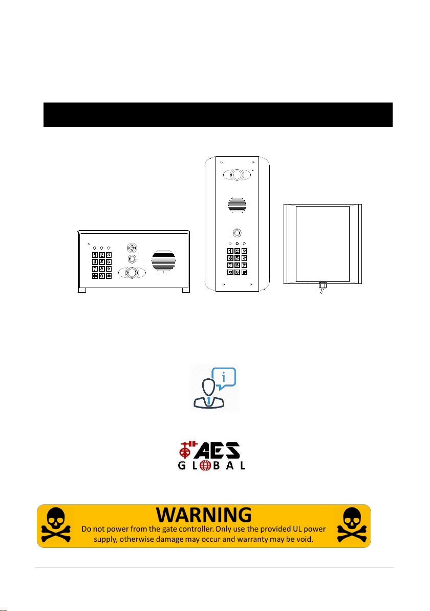
Predator-WiFi (PRO 2)
PROFESSIONAL INSTALL ONLY
Do NOT give this manual to end user!
Manual Version 1
The manufacturer cannot legally offer technical support to non-qualified gate
or door installers. End users should employ the services of a professional
install company to commission or support this product!
Tip: Site Survey BEFORE you begin. See Page 3!

2 | P a g e
Index
Section
Pages
Site Survey
3
WiFi Setup
4-8
Answering on Android
9
Answering on Apple
10
LAN setup
11
Installation
12
Power
13
Intercom Module Wiring
13
Keypad Module Wiring
14
Output Connections Example
14
Adding Additional APP Users
15
Other Settings
16
Sounds, Volume & Speech
17
Using the APP
18
Keypad Programming
19
Using the Keypad
21
Troubleshooting
21
Revision Changes
23
3 | P a g e
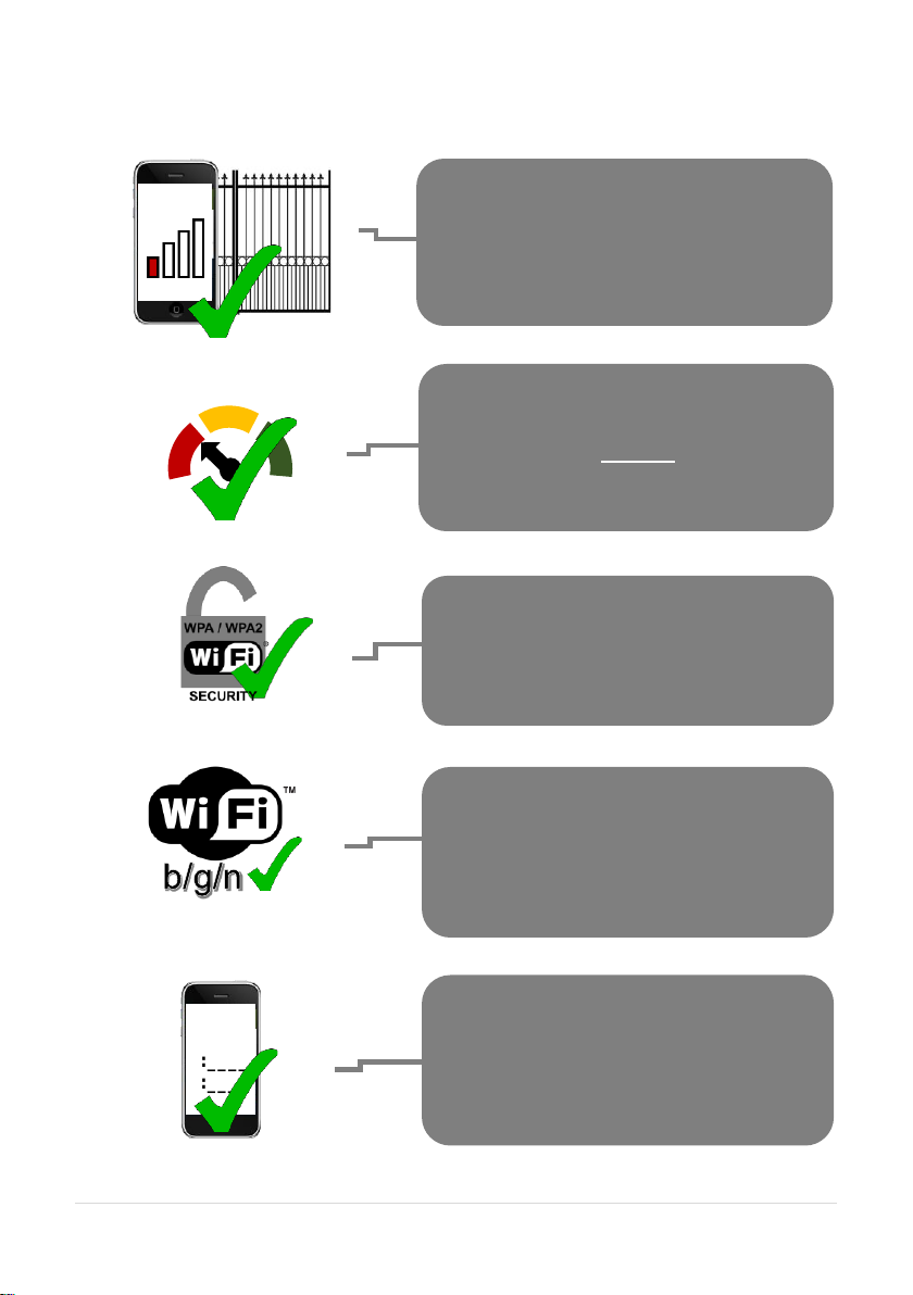
Site Survey
WiFi
Mbs
Slow Fast
YES!
I have some wifi signal at the gate with my
phone! If not, STOP. You will need some form
of wifi extender, or repeater, or LAN/CAT5
cable!
YES!
I have at least 1 Mb UPLOAD speed. If not
STOP! This system may operate intermittently
remotely or have delayed PUSH notifications.
YES!
My wifi Internet Security is WPA or WPA2 or
better.
YES!
My wifi network supports 802.11 b/g or n (2.4g
frequency networks). Note: This device cannot
run on “a” or “s” type networks (these are 5G
frequency).
SSID
1:____
2:____
3:____
YES!
The network I am trying to connect to is a
single network without duplicate SSID
networks of the same name.
4 | P a g e
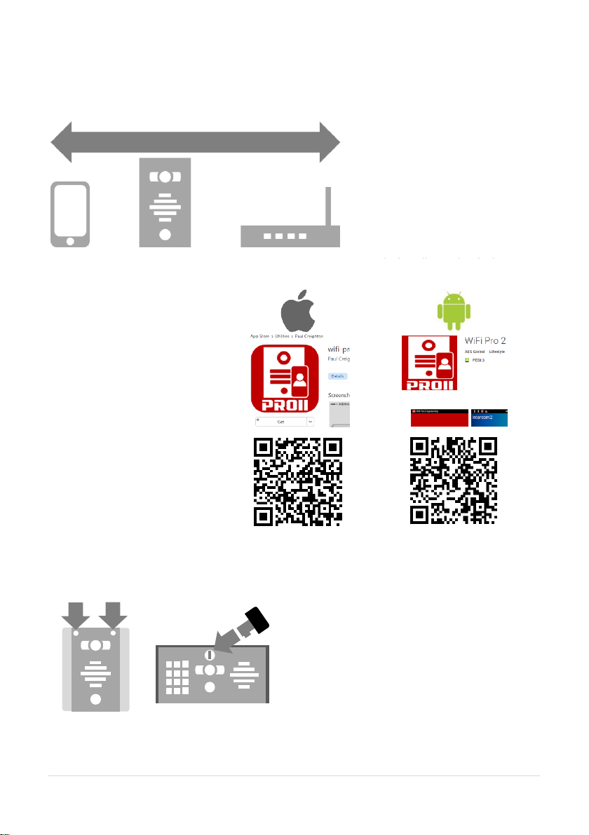
Wifi Setup
Step 1
Step 2
Step 3
Open the intercom and connect antenna.
Do not install the intercom.
Power it up beside the router so
that you can perform the
configuration with the home
owners phone beside the
intercom and router.
Note: If you skip this step and
proceed directly to installation,
technical support may request
you go back and perform this
Download and install the app
on the end-user’s phone.
Search for wifi PRO 2 and find
the icon, or scan the QR code
if the phone has a QR scan
app.
Tip: Be sure to accept ALL
permissions during install,
otherwise you will experience
problems later!
3-4 feet / 1 metre
Architectural or “Portrait” oriented models
will have security screws at the top.
Loosen only these with the security
screwdriver provided.
Pedestal style “Landscape” orientated
units will have a locking key.
Loosen top screws
Use Key on lock
Portrait wall
mount style
Landscape
Pedestal Style
5 | P a g e
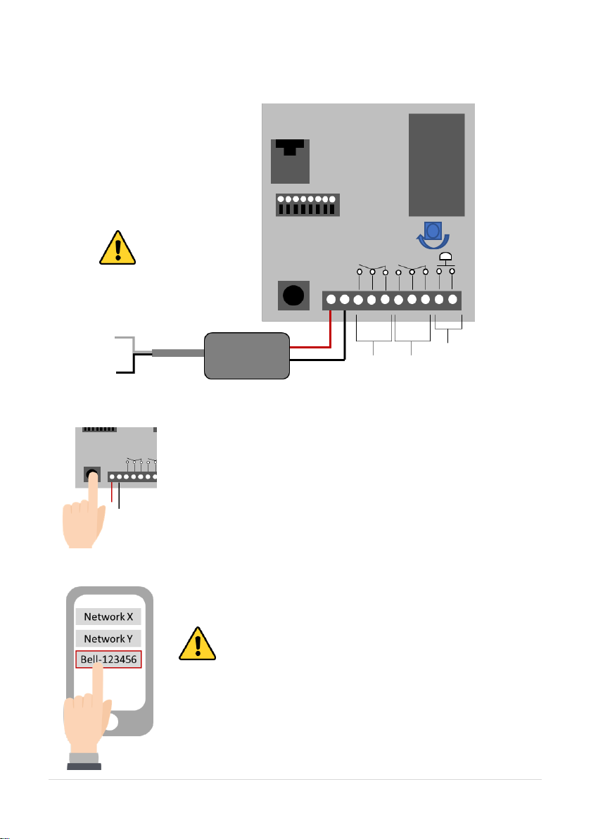
Step 4
Connect 24v DC power with the power supply provided.
Step 5
Step 6a
24v DC PSU
110-250v
mains in
WARNING
Mains electricity to be
wired by qualified
electrician only
+24v
GND
N/O
COM
N/C
Relay1
Relay2
Exit button
RJ45 Ethernet
Ethernet Terminals
CPU &
Transmitter
Code
Button
Press and HOLD the code button for more than 3 seconds. A tone
will be heard.
The intercom will now begin to transmit its own wifi network called
BELL-XXXXXX (where XXXXXX is the 6 numerical digits from the
serial ID number).
>3 seconds
With the user’s phone, search for available wifi networks and connect
to the BELL network.
TIP: Your phone needs to be within range of the intercom to detect
this network.
+ - SPK

6 | P a g e
Step 6b
Step 7a, 7b, 7c
Step 7d, 7e
Wifi passcode
Enter the default pass code 123456789 and the users phone should now
be connected directly to the intercom.
Press CONNECT on android devices and DONE on apple devices.
After pressing
SEARCH, the APP
will now search for
the intercom and
should detect it.
Intercom ID will be auto filled.
Enter “admin” for the main
user.
Enter “123456789” as the
default password and press
the TICK as shown.
7 | P a g e
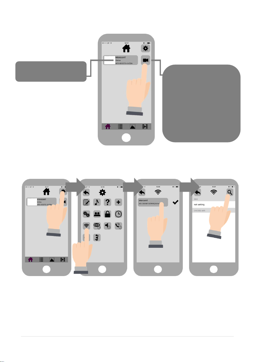
Step 8
Step 9a, 9b, 9c, 9d
Note: The intercom and phone are directly connected in a point to point link. Although we know
the intercom is fully operational, we now need to connect it to the local wifi network.
The intercom is now searching the area for wifi networks and will display all compatible networks
on the App screen.
Press the Video icon to
view live video.
Note: at close proximity,
you will experience acoustic
feedback. This is normal.
TIP: If you can view live
video, and hear acoustics,
then this proves that the
intercom hardware is
working as it should.
Should be showing
ONLINE status.
8 | P a g e
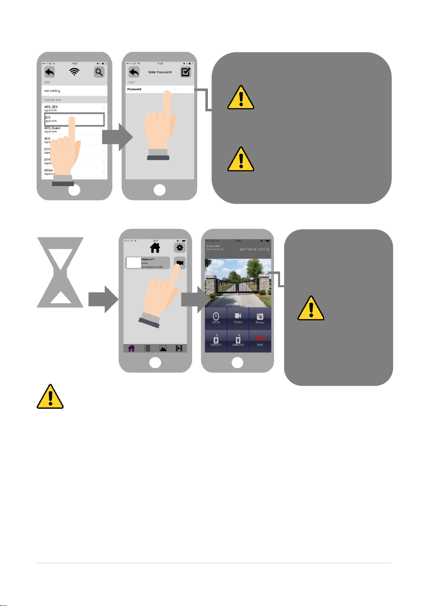
Step 9e, 9f, 9g
Step 10
Diagnostic Tips
1. Intercom is showing online status, but the video feed shows “fetching”.
A. This can be caused by poor power cable extended to the intercom, weak wifi, or too many
devices connected to the wifi network and the router is incapable of managing the workload.
2. Intercom is not showing online status.
A. This can be caused by incorrect wifi password created, or wifi dropping in and out due to weak
signal.
3. I can see video but there is no audio on the phone or there is no audio at the intercom.
A: This can be caused by the audio settings being too low on the phone, or permissions for the
app were not accepted during app install. Check microphone permissions for the app in the phone
settings.
4. The status is showing online, then connecting, then online again.
A: This is normal when a phone roams between two wifi connections, or between wifi and data.
Make sure the phone is stationary and either has good wifi or a stable data connection.
Enter the WIFI PASSCODE for the
network which you are connecting to.
WARNING: Take care not to enter a
typing mistake. The intercom will accept
any wifi password and will not know if it
is correct or not!
Wifi Signal strength must be at least
25%, or you will have problems!
Wait 60 seconds.
The intercom will now
re-boot and attempt to
connect to the wifi
network with the
password you have
entered.
60 secs..
If you can see live
video and hear audio,
the intercom has
successfully
connected to the
network.
If for some reason this
does not work, try
connecting to the wifi
network again and
double check the wifi
password is correct.

9 | P a g e
Step 11 - Press the call button.
Answering on Android
Intercom
Calling…
The intercom will send a notification message via GoogleTM PUSH
notification service through the internet to the phone. The notification
will need to be accepted, the phone unlocked, and then the APP will
launch to reveal the visitor and give the user an opportunity to either
accept or reject the call..
Swipe down your
notification banner
when called, and press
the Intercom
notification.
Your phone will now
launch the app and
you will see a
snapshot of the visitor
at which point you can
answer or decline the
call.
Press the green icon to
accept.

10 | P a g e
Answering on Apple
Note: Various versions of IOS and Android OS will have different notification acceptance
techniques. Please refer to online support for your device if needed.
Swipe the
notification left
Press “VIEW”
Swipe green
icon to answer
Phone will now
launch app
TIP: Make sure ringer switch is
ON and volume is turned up.
TIP: If you don’t get
notifications then check
settings/notifications and
select the app.
TIP: If there is no voice from the
speaker at the gate, check the
iphone microphone permissions in
Settings/privacy/microphone

11 | P a g e
LAN Setup
This intercom can also be connected to a LAN cable directly from the router or from a repeater or
point-to-point wifi bridge device. Note: Ethernet LAN signals can travel 100m/300ft on CAT5
cable. Longer distances will require a powered switch or repeater every 100m/300ft.
Step 1
Step 2a, 2b, 2c.
Option 1
Connect RJ45 Ethernet
crimped socket.
Test with laptop or LAN
tester first.
Option 2
Use provided springrelease terminals
observing colour code
shown.
Ethernet can travel
up to 100 metres
(320 feet) on
CAT5/CAT6 cable.
Longer distances
will require a switch
every 100 metres
(320 feet).
After pressing
SEARCH, the APP
will now search for
the intercom and
should detect it.

12 | P a g e
Step 2d, 2e
Now you can test the intercom as per steps 10 and 11 in “Wifi Setup” section.
Installation
Intercom ID will be auto filled.
Enter “admin” for the main
user.
Enter “123456789” as the
default password and press
the TICK as shown.
Mount the antenna as
high as possible and
away from obstructions
such as vehicles, shrubs
and trees to maximise
signal strength.
Do NOT mount antenna
at ground level.
Intercom wall/pillar
mounted
Pedestal
mounted
version
Antenna cable (do
not cut or join).
Longer length
options available.
Antenna mounted
inside gate or fence
to improve range.

13 | P a g e
Power
This intercom comes with a 24v dc power supply. The intercom requires up to 2 amps peak
demand at times, therefore power cable is of extreme importance.
It is preferred the 24v dc PSU is installed within close proximity of the intercom. However, on
occasion this may be difficult to achieve. Please adhere to the cable thickness guide below or the
device may be damaged and rendered out of warranty by the manufacturer.
Up to 2 meters (6 feet) use minimum 0.5mm / 18 gauge cable.
Up to 4 meters (12 feet) use minimum 1mm / 16 gauge cable.
Up to 8 meters (25 feet) use minimum 1.5mm / 14 gauge cable.
Intercom Module Wiring
24v dc PSU
24v dc PSU
Never use fine gauge
cable such as alarm cable
or CAT5 to power this
device. Doing so will void
the manufacturer’s
warranty!
24v DC PSU
110-250v
mains in
WARNING
Mains electricity to be
wired by qualified
electrician only
+24v
GND
N/O
COM
N/C
Relay1
Relay2
Exit button

14 | P a g e
Keypad Module Wiring
Output Connections Example
24vdc
(already
pre-wired)
Relay1
Relay2
N/C
COM
N/O
Egress
Advanced
Connections
Relay3
N/C N/O
Relay2
Full/Auto
COM
N/O
COM
N/C
COM
N/O
Intercom board
Keypad board
Electric Gates
Gate
Controller
Magnetic
Lock
N/C
Other control
device
12v DC
(Not supplied)

15 | P a g e
Adding Additional APP Users
Additional users MUST be added with individual user names. Do NOT use the same username.
ADMIN Phone
ADMIN Phone
ADMIN Phone
ADMIN Phone
Enter a NEW
username &
password
Note how
existing users
can be deleted
New Phone
New Phone
New Phone
New Phone
Be sure to enter NEW
username & password as
created by the admin
phone.

16 | P a g e
Other Settings
Edit Intercom
details
Ring tones
Check APP
version
Add an intercom (can
have up to 6
doors/gates calling one
device)
Add/edit users
Turn off config
mode (extra
security)
Wifi settings &
signal
strength
Set max monitoring
time
Change relay times (1-
9 secs)
Set time zone +
(daylight saving
adjust)
Set max talking
time.
Set max ringing
time (from intercom)
Set sound option.
Duplex, simplex1,
simplex2.
Reboot
intercom

17 | P a g e
Sound, Volumes and Speech
This intercom is capable of full duplex speech, which means two people can have a conversation
and appear to speak at the same time. Since various manufacturers of android phones, iphones
and tablets all differ in acoustic performance, and different users may require varying levels of
volume on their own handset, it may be possible to setup some devices in full duplex mode but
others may need to be set in half duplex mode (phone user will press to talk). This may also be
required if a phone is in a particularly noisy environment, or the intercom is located near a busy
main road with high levels of traffic noise.
Choose the speech option which
best suits the individual and he
device being used.
+ - SPK
Suggest 80% MAX
volume
Suggest
50% MAX
volume on
“Press and Hold” option
appears when device set to
half duplex 1 or 2.

18 | P a g e
Using the APP
Settings
View Camera &
listen
Thumbnail preview
Home
Call Log (shows
images of visitors
whom calls were
accepted or
previewed on this
device.
If you took
snapshots of a
visitor while on a
call, view them
here.
If you took video
recordings of
visitors, you can
view them here.
Press to extend
talking time
Gate/door release 1.
Momentary press to
TRIGGER.
Press and HOLD for
3 seconds to LATCH
open.
Momentary press
again to UNLATCH
Record video of
visitor to your
phone. (some
versions of phone
need codec
installed to play
this format).
Take pictures of
visitors on your
phone.
Gate/door release 2.
Momentary press to
TRIGGER.
Press and HOLD for
3 seconds to LATCH
open.
Momentary press
again to UNLATCH
End call.
Android users press BACK button to run in
“background” mode or “close app” to save
battery. (notifications will launch app again)

19 | P a g e
Keypad overview
This keypad has 3 outputs, all independent from the intercom/app relays. The diagram below
shows the LED indicators which indicate programming and relay status information.
RED when incorrect codes entered and outputs are locked out.
1 2 3
4 5 6
7 8 9
* 0 #
SLOW FLASHING - in normal standby mode.
ON in programming mode.
ON when relay 3 activated.
GREEN when output 1 activated.
RED when output 2 activated.
CLEAR when output 3 activated
FAST FLASHING – Wrong code entered / error.
TIP: After power up, as a security precaution, the keypad cannot be programmed for 60 seconds.
Once this time elapses, you may begin.
TIP: Flashing amber LED is normal standby mode!
Keypad Programming
0 0 0 0 * *
Quick start guide
1) Enter programming mode (amber LED should be ON)
1 0 2 0 0 ? ?? ? #0
2) Enter a new user code...
* *
3) Exit programming mode
4) Enter the new user code to check the relay clicks.
Full Keypad programming
Enter programming mode..
0 0 0 0 * *
Exit programming mode..
* *
Enter a new ENGINEER/INSTALLERS code…
Go into programming mode firstly then enter the following sequence…
Location
0 1 ?? ? ?
4-8 digit code Validate
#
Tip: The engineer code
must be the same length as
user codes. If using a 6 digit
engineers code, then user
codes must also be 6 digits
long etc.
The unit is now in programming mode. Amber LED on the
keypad should remain permanently on. 0000 is the default
programming passcode.
The unit should exit programming mode and the amber LED
should start flashing again.
Replace ???? with your new ENGINEERS
code.

20 | P a g e
Enter or delete new user/Homeowner codes
There are 3 groups of user codes. Group 10 for relay 1, group 20 for relay 2, and group 30 for
relay 3. The programming sequence is shown below…
Memory locations
000-999 for relay 1
001-100 for relay 2
001-100 for relay 3
1 0 2 0 0
10= relay 1 codes
(1000 available)
20= relay 2 codes
(100 available)
30= relay 3 codes
(100 available)
? ?? ? #0
2= add code
5= delete code
Pin code 4-8 digits Validate
Example: Add user 31 to have access code 5555 operating relay 2….
2 0 2 0 3 5 55 5 #1
Group 2 Add code Location 31 Pin code 5555 Validate
Programming relay output times and modes…
? ?
0
1 -
0 = start / stop toggle mode (latching)
1-99999 = seconds momentary operation
9 9 9 9 9
or
#
51=relay1
52=relay2
53=relay3
Validate
Delete a user code even if you don’t know the code…
? ? 5 ? ?? #
10=relay1
20=relay2
30=relay3
Delete code ID location to be deleted Validate
Delete an entire group of codes
? ? 0 9 99 #
10=relay1 group
20=relay2 group
30=relay3 group
Super delete code Validate
Programming super user codes…
A super user code can activate any of the 3 relays
Location
0 2 ?? ? ?
4-8 digit code Validate
#
Restoring defaults
When in programming mode, you can enter the following sequence…
9 9 99 #

21 | P a g e
When the engineers/installers code is forgotten….
1) Wire a push button (or replicate with wire link) across the Egress terminal and (-)GND.
2) Switch off power for 1 minute.
3) Switch ON power.
4) during the first 60 seconds, press the EG button once to enable the function.
5) Enter the following code..
8 0 08 * *
The keypad should now be in programming mode, ready to accept new data. Change the
installers/engineers code now as per instructions above.
Using the keypad
Using the standard codes…
Once you have exited out of programming mode, simply enter the user code.
Using super user codes
?? ? ? # 1
Activate output 1
?? ? ? # 2
Activate output 2
?? ? ? # 3
Activate output 3
Troubleshooting
It is worth remembering that when you install this intercom, you are literally only supplying 25% of
the overall system. The other 75% already exists with the customer. Namely the router, the wifi
network, and the phones or devices.
Anything can go wrong with any part of that entire system. Therefore, it is a useful exercise to
attempt to prove to the customer that the intercom hardware is working and operational before
attempting to diagnose the root cause, especially when connected wirelessly to a network.
If the intercom is connected via wifi to the network, it is very useful to press and hold the code
button on the board, then connect the phone DIRECTLY to the BELL wifi network (must be within
wifi range of intercom). Open the app, and show the customer that when the phone is connected
directly to the intercom, there is video and two way speech. The job is then to find out what part of
the installation or overall system is causing the problem since the intercom hardware has been
proven as operational.
We can say without doubt that when we do get hardware failures, the above process will not work
and you will not get video and voice to the phone in a direct connection like this.

22 | P a g e
Below are the most common causes of problems with installs, starting with the most common first.
Problem/error
Symptoms caused
Solution
Wifi too weak at gate
App showing offline status,
video image shows
“fetching, long lag on calls,
intermittently showing
online/offline, delayed push
notifications.
Increase the height of the antenna
if possible, install a wifi booster
either inside the house near the
front of the property, or a loft or
eaves mounted external wifi
booster, or install a CAT5 cable
from the intercom to the router.
Wrong power cable (too
thin) installed from 24v
adaptor to the intercom,
or power adaptor too far
from intercom.
Delayed push notifications,
video lag, voice problems,
freezing, relays not opening
the gate.
Change the power cable to
specifications shown within this
manual.
Too many devices on
home network
Lagging video or audio,
delayed notifications, status
showing intermittently
online/offline, no or
randomly operation of push
notifications.
Turn off as many other devices as
possible, reboot the router and
then try again. If the unit works, it
proves to the customer that their
router needs to be upgraded to
handle the demand.
Several wifi networks
using the same SSID
Intercom works well
sometimes and not well
other times. The wifi signal
strength on the app wifi
screen can sometimes be
strong and other times
weak.
The intercom is jumping between
networks depending on traffic and
other devices connected to the
same node. It is advisable to
change the SSID name of the wifi
network closest to the intercom to
something individual.
Incorrect wifi password
entered during setup
Offline status. Will not
connect to the network
Try process again. Check the
same wifi password works on your
phone (forget the network and reconnect using the same
password).
Additional user added
incorrectly.
Can randomly display status
“id already in use”
When an additional user was
being added, the process was
done incorrectly. Additional users
MUST be added by the admin
device first, with separate
usernames created for each. The
new usernames and passwords
must be used by the new devices
as shown in this manual to logon
to the intercom.
Commercial firewall
App shows online when
phone is in the same
network but offline when
phone on 3G/4G or on a
remote wifi network, App
works fine remotely to view
gates but push notifications
are not working at all.
This will be a job for the IT
provider for the business. A port
will need opened to allow P2P and
PUSH notification traffic to pass
through the firewall.
Recommended unassigned ports
which your network administrator
can open are 6806, 6809 and
9123, 9124.

23 | P a g e
Insufficient upload
speed
App shows online status
locally and when phone is
remote, but push
notifications may be
delayed, or video lag, or
showing “fetching” on video
screen.
This will need discussed with the
ISP / broadband provider.
Change History
Top
version
Panel
version
PCB
version
Firmware version
IOS app
version
Android
app version
1 2 1.0
4.11.12.21.20171121
1 1
Regulatory Compliance
FCC Id: 2ALPX-WIFI-IBK
Grantee: Advanced Electronic Solutions Global Ltd
This device complies with Part 15 of FCC rules. Operation is subject to the following two
conditions: (1) this device may not cause harmful interference, and (2) this device must accept
any interference received, including interference that may cause undesired operation.
Output power listed is conducted. This device must be installed to provide a separation distance
of at least 20 cm from all persons and must not be co-located or operating in conjunction with any
other antenna or transmitter. End-users and installers must be provided with antenna installation
instructions and transmitter operating conditions for satisfying RF exposure compliance. This
device has 20MHz and 40 MHz bandwidth modes.
EU-RED Declaration of Conformity
Manufacturer: Advanced Electronic Solutions Global Ltd
Address: Unit 4C, Kilcronagh Business Park, Cookstown, Co Tyrone, BT809HJ, United Kingdom
We/I declare, that the following equipment (Video intercom), part numbers:
Wifi-iBK, wifi-iB, wifi-ABK, wifi-AB, wifi-BD, wifi-BEK,
wifi-BEik, wifi-Bei, wifi-BFT-KPAD
Complies with the following essential requirements:
EN 301 489-1 V2.2.0 (2017-03) (Electro-Magnetic compliance)
EN 301-489-17 V3.2.0 (2017-03) (Electro-Magnetic compliance)
EN 62479:2010 (Maximum output power)
EN60950-1:2006+A11:2009+A1:2010+A12:2011+A2:2013 (Electrical Safety)

24 | P a g e
The manufacturer cannot legally offer technical support to non-qualified gate
or door installers. End users should employ the services of a professional
install company to commission or support this product!
 Loading...