

Page 1
P a g e | 1
..PROFESSIONAL INSTALL ONLY..
Do NOT give this manual to the end user / home owner
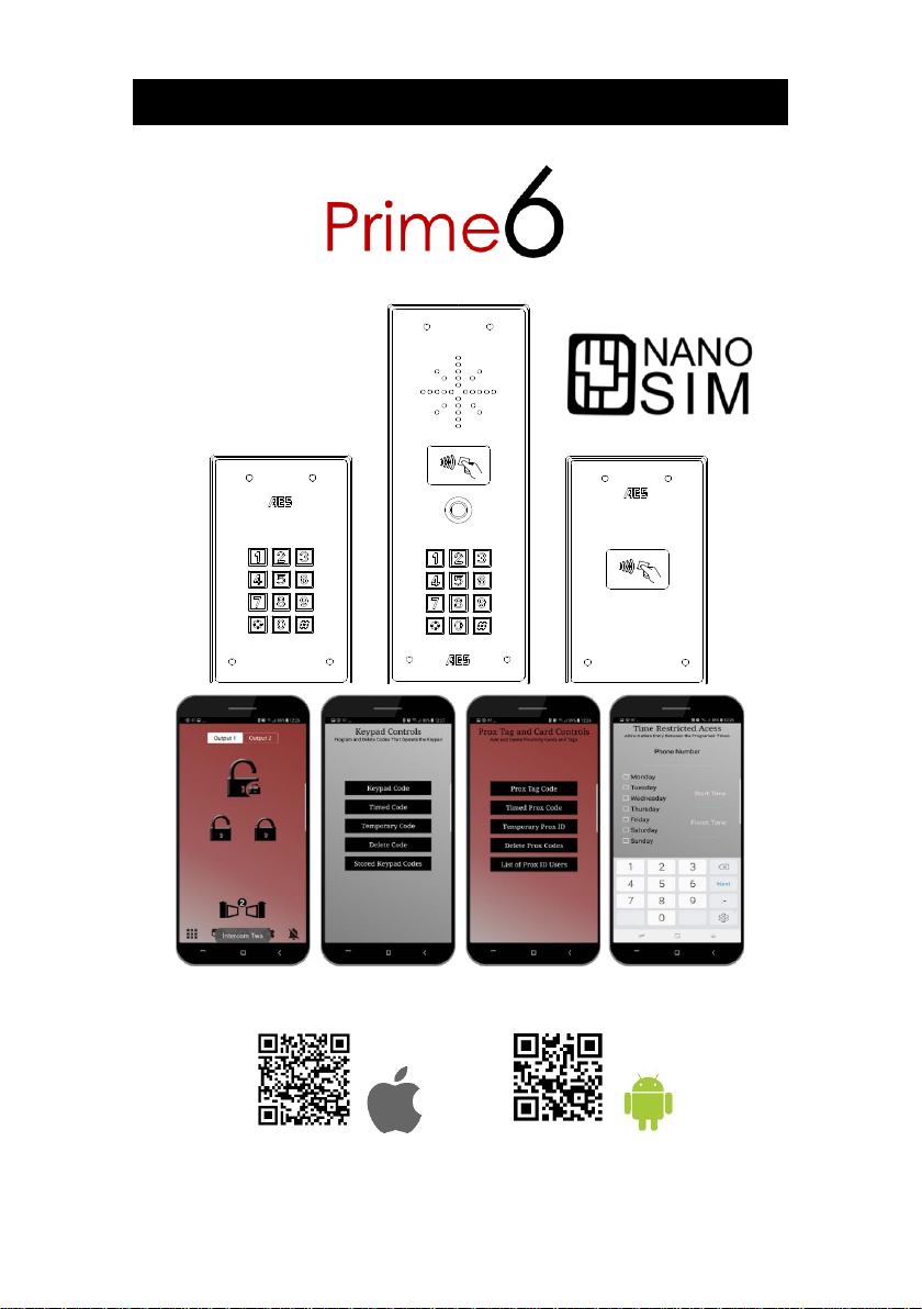
Advanced GSM Intercom System (3G)
Scan the QR code below to install the INSTALLER App
Page 2

P a g e | 2
Contents
Overview of System
…………….Pg 3
Site Survey
…………….Pg 3
SIM card
…………….Pg 3
Power
…………….Pg 3
Installation
…………….Pg 4
Architectural & Hooded panels
…………….Pg 4
Flush Panels
…………….Pg 4
Inserting the SIM card
…………….Pg 4
Connecting the antenna
…………….Pg 5
Connections on GSM controller
…………….Pg 5
Connecting of slave devices
…………….Pg 6
Powering Up
…………….Pg 6
Installing Programmers App for first time
…………….Pg 7
Programming a Brand New Install
…………….Pg 8
Programming an Existing Install
…………….Pg 8
Programming
Check Reception
…………….Pg 9
Programming Dial Out Numbers
…………….Pg 10
Program Caller ID Numbers
…………….Pg 11
Programming Additional Features
…………….Pg 12
Volumes
…………….Pg 13
Dial Times & Talking Time
…………….Pg 13
Service Calls
…………….Pg 14
Diagnostic Info
.……….Pg 14-15
Pass Codes
…………….Pg 16
Relay Times
…………….Pg 16
Notifications
…………….Pg 17
Keypad Programming
………….Pg17-19
Auto Relay Trigger Times
…………….Pg 20
Client List on iphone
…………….Pg 20
Client List on Android
…………….Pg 21
Clock Sync
…………….Pg 21
Daylight Saving
…………….Pg 22
Do Not Disturb
…………….Pg 22
After Hours / Out of Hours
……….Pg 23
Proximity card & tag programming
……….Pg 23
Complete List of Parameters
……….Pg 26
Troubleshooting
……….Pg 27
Change History
……….Pg 30
Page 3
P a g e | 3
Overview of System
Please read this entire manual before attempting to install this system.
This system should only be installed by a professional automatic gate installer or access control
specialist dealer.
It is recommended that the system be set up, configured, commissioned and tested on a
workshop bench before taken to site for installation.
Site Survey
Before installing this system, you need to be sure that there is good mobile GSM cell coverage in
the area it is to be installed. It is recommended that you conduct a site survey, and check
reception on the site for a GSM network. If reception is poor in the area, then this system is not
recommended.
SIM Card
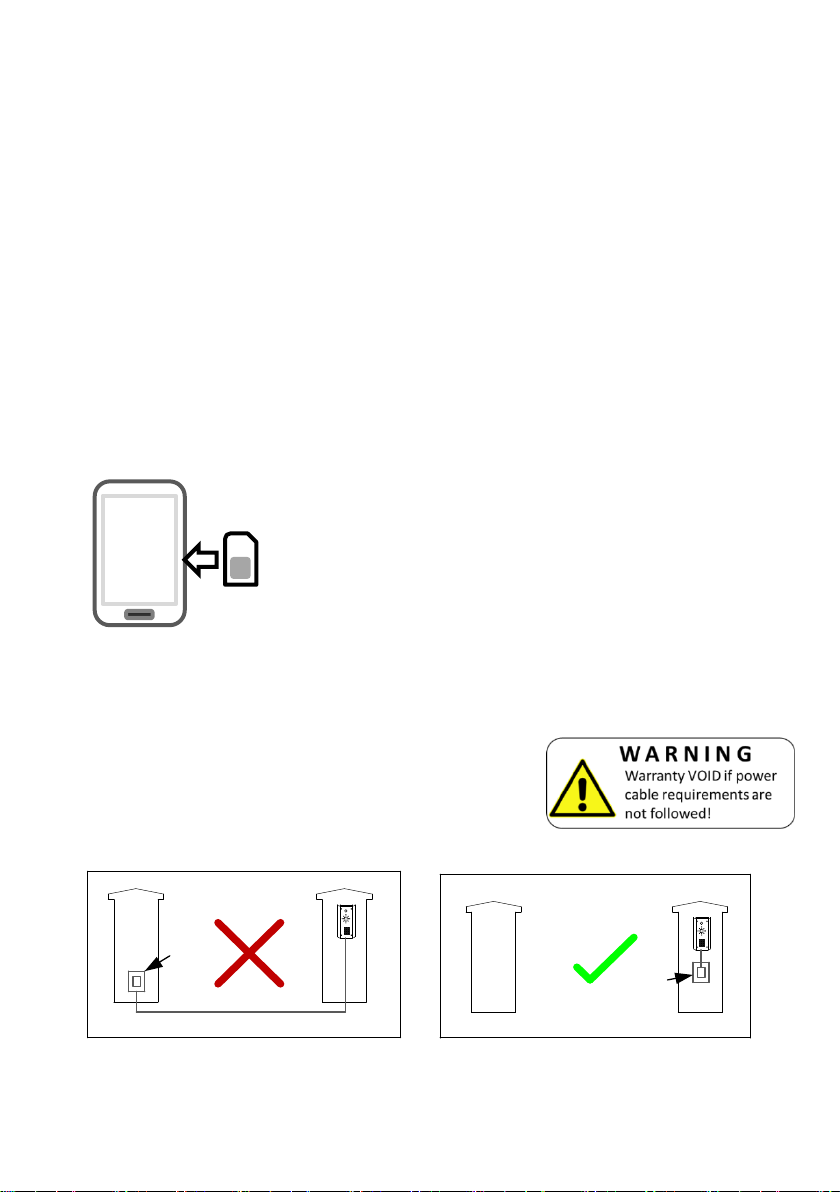
You will need a SIM card to use this system. It should be a regular voice and SMS text SIM card
and capable of running on 2G/3G/4G service. Do not use a data only SIM, as this is only for
tablets and will not work in the unit.
Power
TIP: Most technical calls received are due to installers using CAT5 or alarm cable to power
the unit. Neither are rated to carry enough power (2 amp peak). Please use following
cable…
Up to 2 metres (6 feet) – Use minimum 0.5mm2 (18 gauge)
Up to 4 metres (12 feet) – Use minimum 0.75mm2 (16 gauge)
Up to 8 metres (24 feet) – Use minimum 1mm2 (14 gauge)
Using insufficient power cable thickness will cause excessive stress on electronic components,
and therefore void the manufacturer’s warranty.
24v Power
adaptor
24v
Power
adaptor
To avoid such problems, it is recommended (and is good practice) to locate the power supply as
close to the transmitter as possible. This avoids power cable noise and interference and enhances
the lifetime of the product.
1) Ensure the SIM has calling credit, and can make and
receive calls on a mobile cell phone.
2) Check that the SIM is not locked to a phone and can be
used in other devices.
3) Check that the SIM does not have a PIN code request.
4) Disable voicemail service on the SIM.
5) You are now ready to begin programming.
Page 4
P a g e | 4
Installation
Entrance
Pillar
Speech
Unit
4-5 feet
minimum
200mm
min
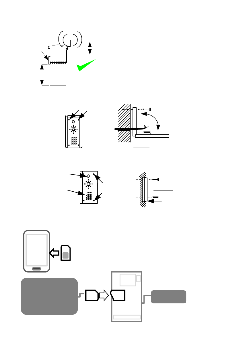
Architectural & Hooded Panels
Loosen top 2 screws only
Hinge front door
Side View
Flush Panels
Call Button
Optional keypad
module
Remove
Side View
Flush with surface
Tip: Use appropriate fixings to ensure the intercom cannot be removed from the wall.
Inserting the SIM card
Please ensure the SIM card is a 2G/3G compatible NANO SIM card.
The SIM may also be 3G and 4G capable as well, as long as both
the SIM and the network also support 2G/3G. Do not use a SIM card
for a tablet, as these only support data, and do not support voice and
SMS. You simply require a mobile phone type SIM card.
Do not remove the protective film until the system is
fully installed and working. Protective coverings are
there to protect the intercom from scratches and
marks during installation.
TIP: Antenna height is best higher than intercom for
cleaner audio and also better reception.
TIP: Avoid sharp bends on the antenna cable.
SIM
GSM Board
POWER OFF
45 chamfer IN.
Copper pads DOWN.
Page 5
P a g e | 5
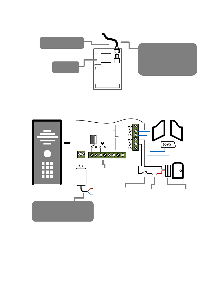
Connecting the Antenna
Connections on the GSM Controller
?
+
24v
dc
N/C
COM
N/O
N/C
COM
N/O
1
2
Antenna cable
TIPS:
Avoid bending.
Avoid excess cable inside
call station.
Do not cut.
Modem
WARNING: Connect by
qualified electrician only
Limit Switch
input
Exit
button
Relays
Auto Gates
Other
device, e.g.
exit button
Separate
power
supply
Magnetic lock
on small gate
or door
Page 6
P a g e | 6
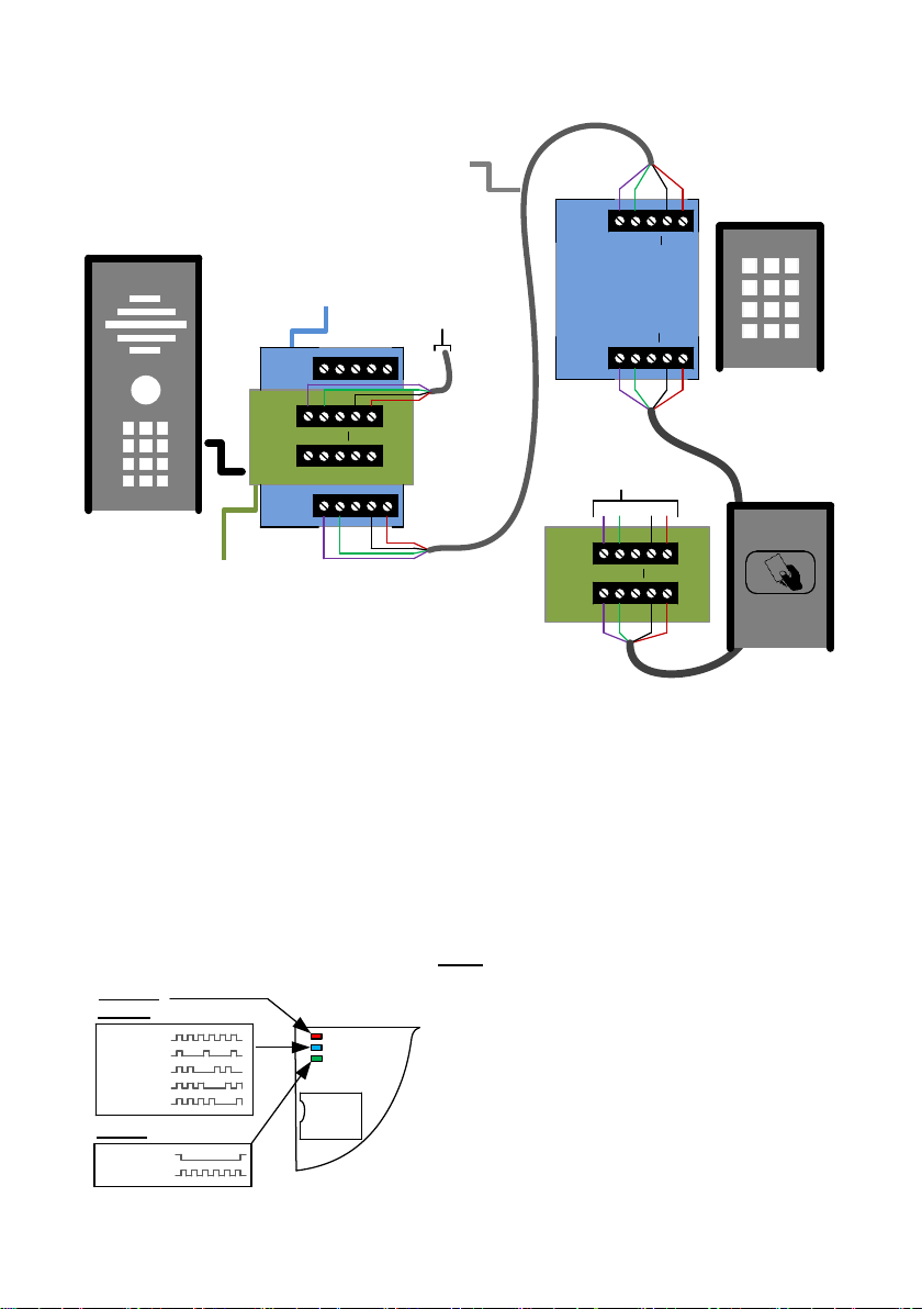
Connecting of Slave Devices
1 2 3 24v
OUT
IN
OUT
IN
OUT
IN
1 2 3 24v
OUT
IN
1 2 3 24v
1 2 3 24v
Notes:
Up to a total of 8 devices can be connected to the one SIM module.
All keypads will be programmed with the same codes as the main unit.
All Prox units will store the same Prox cards.
Powering slave devices locally for longer distances.
Powering Up
Perform a final check of wiring and ensure the antenna is connected before switching on the
power. Once the power is switched on, the power LED should illuminate.
Power LED
CPU LED
GSM LED
Searching
1 bar signal
2 bars signal
3 bars signal
4 bars signal
System booted
Booting
TIPS:
My GSM LED is still searching…
-Check the SIM card is registered and can make a
call in a phone.
-Check the SIM card is seated correctly. Power off,
clean the contacts on the SIM and the GSM unit,
and reinsert the SIM.
-Check power cable distance and thickness.
-Increase antenna height.
-Change network.
-Move antenna away from metal objects & shrubs.
-Fit a high gain antenna.
To next
device
Optional
Keypad
Optional
Prox reader
Optional Slave
Keypad
Optional Slave
Prox Reader
CAT5 (10m max)
100m if device powered separately
To next
device
Page 7
P a g e | 7
Installing the Programmer APP for the first time
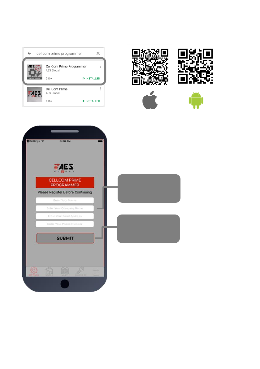
1. For android or apple devices you can download the AES programming app called “Cellcom
Prime Programmer” (or scan QR code below).
2. Open the app and allow all permissions (Android users).
Register your details
first time for support
registration.
Press Submit and
send your details via
email client.
Page 8
P a g e | 8
Programming a Brand-New Install
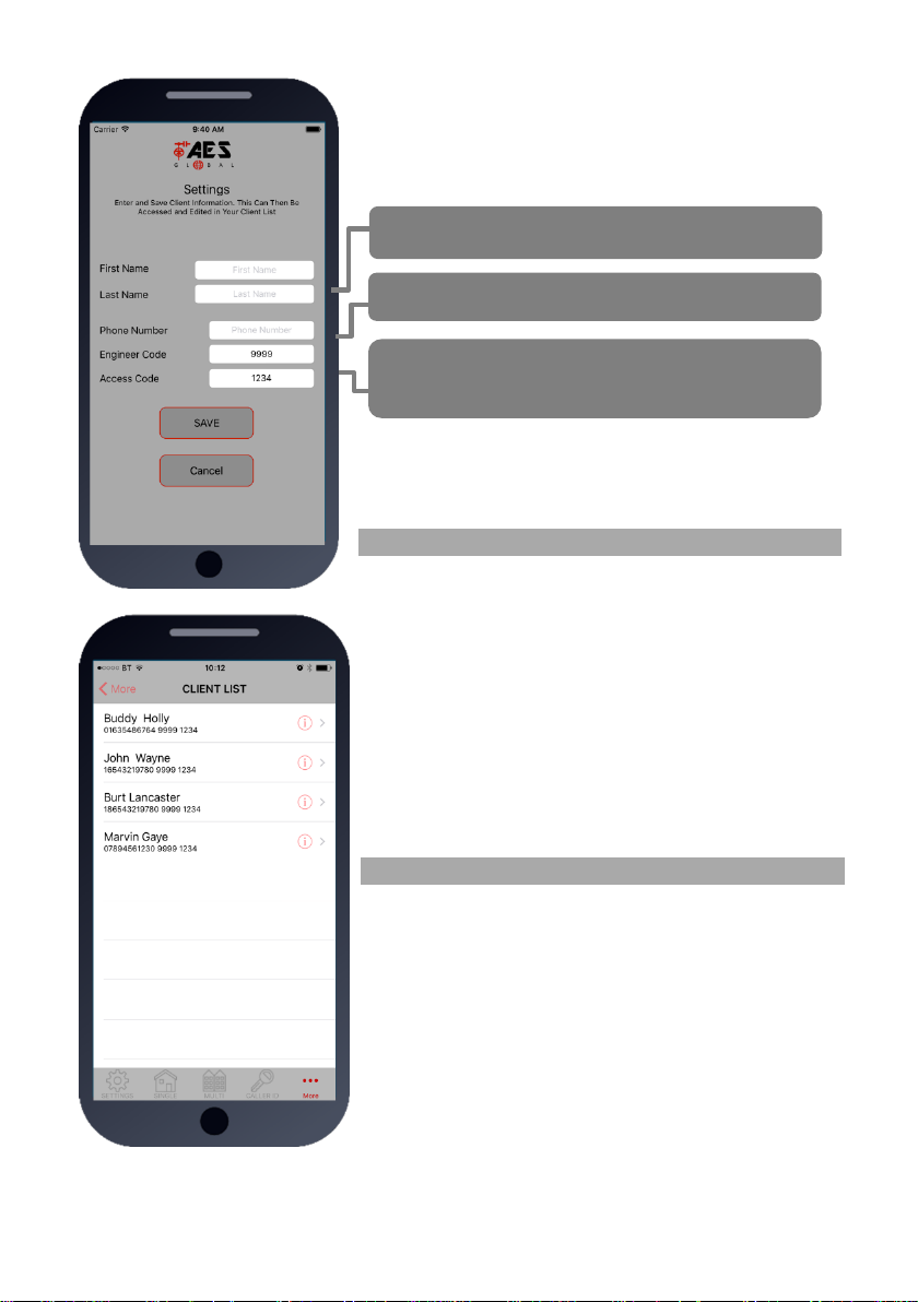
Press SETTINGS to reveal the screen shown. This screen will
store details for the client.
Now you are ready to begin programming!
Programming an EXISTING Install
1.Go to MORE>CLIENT LIST to reveal the screen shown.
2.Press and HOLD to select the desired client.
3.Iphone users press the info symbol. Android users press and
hold the client, and then press upload to begin programming.
Now you are ready to begin programming!
Enter name or site name for customer.
Enter INTERCOM SIM phone number.
Default Engineer’s and user`s pass codes. These
can be changed later.
Page 9
P a g e | 9
Programming
Now that you have either entered a new client, or selected an existing client from the client list,
you are now ready to begin programming.
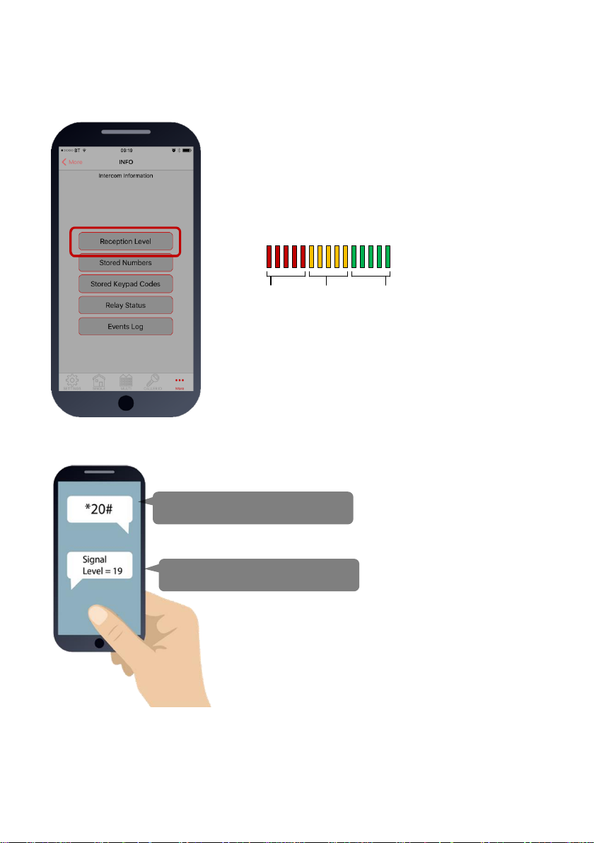
Note: SMS string= *20#
Step 1: Check Reception
Go to MORE>INFO & press the reception check button.
On Android the app will automatically send a SMS string (*20#)
to the intercom.
On iphone, users will be taken to their SMS screen to
confirm before sending the string. The intercom should then
reply with a signal level between 1 and 31.
1-12
Poor
13-20
Medium
21-31
Good
For good performance, signal level on 2G should be at least 13.
On 3G products it should be no less than 10.
TIP: If signal is lower than recommended, then take IMMEDIATE
action. Change network if possible, or use an optional high gain
antenna. Check power cable is within recommended
specification. (Poor power cable can lower reception).
SMS message sent to intercom.
SMS reply to your phone.
Page 10
P a g e | 10
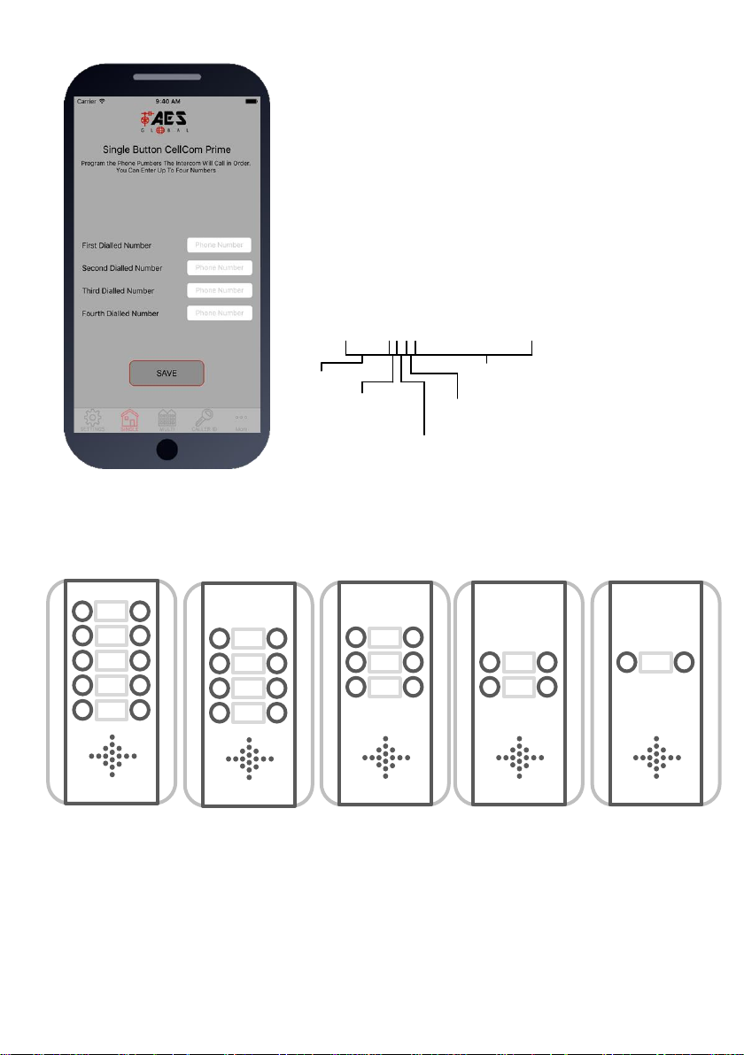
Programming dial out numbers for multi button versions
Please note the position of the buttons on the above panel options. For example, if you have a 2
button panel, you will be programming dial out numbers for buttons 3 and 8. For a 4 button panel,
the corresponding button locations are 2,3,8 and 9.
Step2: Programming Numbers for the
intercom to call on button press.
1.Press the SINGLE home icon for a 1 button system, or MULTI
for a 10 button system.
2. Simply enter cell phone numbers and/or landline phones
which the intercom is to call when the call button is pressed. (10
button model please enter button number).
3. Press SAVE. Note: iphone users will be taken to their SMS
screen to confirm the SMS string (press send).
4. The intercom should reply with an SMS to your phone
showing the SMS string and an OK status.
SMS Programming Format:
9999#111telephonenumber#
Pass code
Function code
(add number)
Data
Button number
(1-10)
Telephone number
position 1-4
E.g. 9999#111firstnumber#112secondnumber#113thirdnumber#
10
9 87 6 5 4 3
2
1
4 4 3 3 3 3 2 2 2
1
10
99 9 88
887
7
Page 11
P a g e | 11
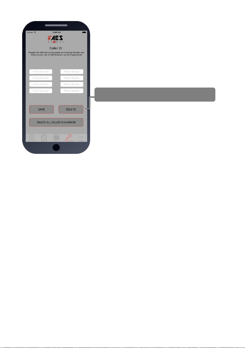
Step3: Programming Caller ID access
numbers (100 max).
1.Press the CALLER ID button.
2. Simply enter cell phone numbers of visitors whom should
have access with caller ID (up to 8 at a time).
3. Press SAVE. Note: iphone users will be taken to their SMS
screen to confirm the SMS string (press send).
4. The intercom should reply with an SMS to your phone
showing the SMS string and an OK status.
To delete, enter number above and press delete
SMS Programming Method:
Add numbers -
9999#72telephonenumber#72telephonenumber#
Delete specific number –
9999#73telephonenumber#
Delete all –
9999#73*#
Page 12
P a g e | 12
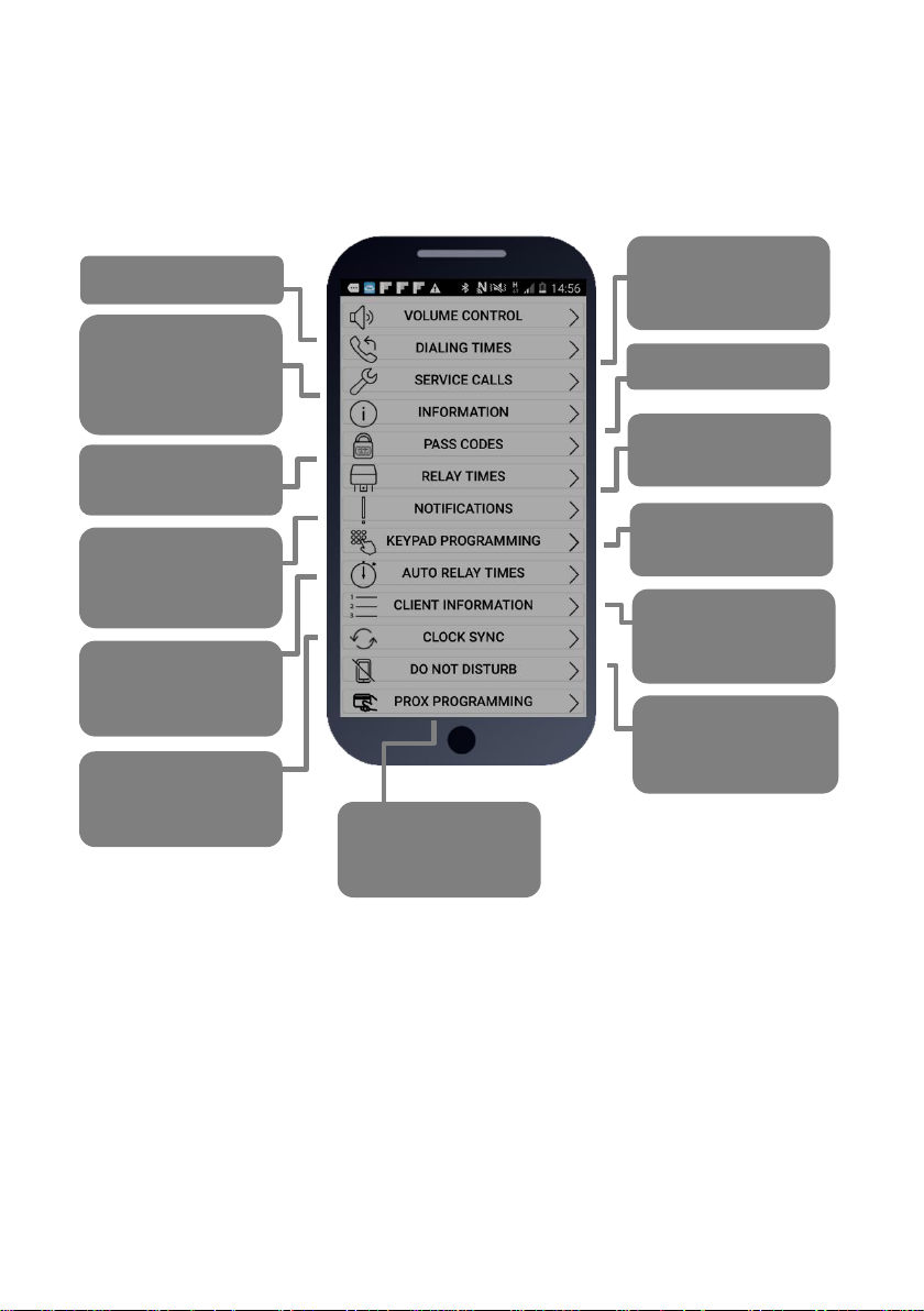
Programming Additional Features
The intercom should now be able to call users and have some basic Caller ID access. Now you
may wish to program additional features for the client, including keypad codes, dialling times (to
avoid voicemail on un-answered calls, auto-trigger times etc.
Mic & SPK Volume
Avoid voicemail
picking up unanswered calls
Service Calls
(prevent SIM being
turned off due to
inactivity)
Diagnostics
Programmer and
user pass codes
Default relay pulse
times
Turn on SMS
notifications when
gates triggered.
Program keypad
code (some models)
Time clock
automatic opening
and closing times
Adjust, add or
delete clients on
your client list
Turn on do not
disturb to disable
call button at night
Turn on Auto-clock
sync after power
failures
Program proximity
cards (model
dependant)
Page 13
P a g e | 13
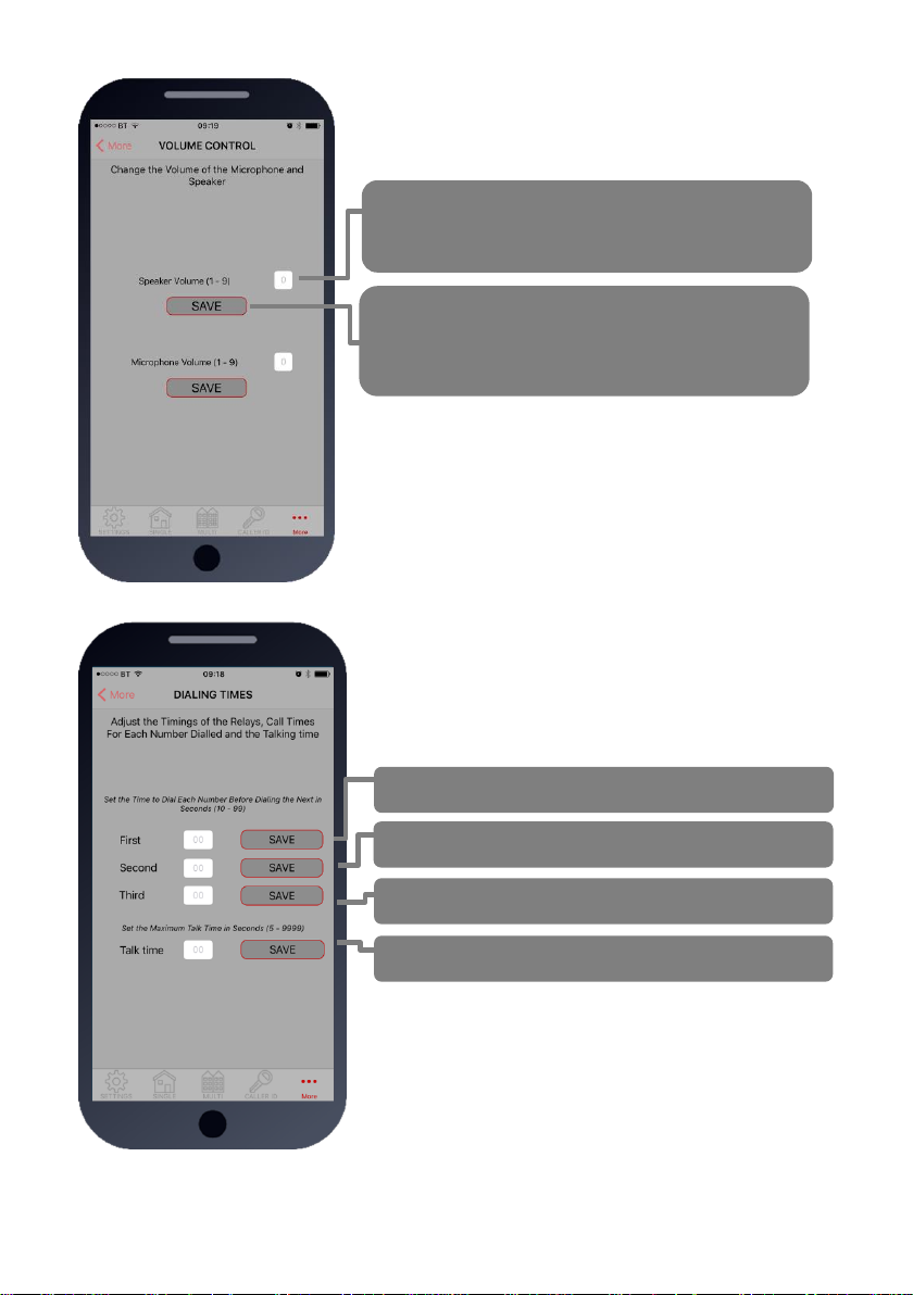
1.Volumes
Adjust speaker and microphone volumes.
Enter required level (1-9) for optimum speech.
TIP: Set as low as possible for good acoustics.
Default = 5
SMS string for Speaker Volume:
9999#3X# (X=1-9, default = 5)
SMS string for Microphone Volume:
9999#4X# (X=1-9, default = 5)
Press SAVE.
TIP: Iphone users will be taken to SMS screen to
confirm message. Android devices will
automatically send the SMS.
2. Dialling Times & Talk Time
Change ringing times on each number to avoid voicemail
picking up a call on un-answered call so the unit can roll over
to the next number.
Note: Default 20 secs (includes 5-8 sec connection time).
Dialling time for first number (default 20 secs)
Dialling time for second number (default 20 secs)
Dialling time for third number (default 20 secs)
Set MAX talking time for all numbers (default 60 secs)
SMS strings:
9999#45XX# (X=dialling time for first number)
9999#46XX# (X=dialling time for second number)
9999#47XX# (X=dialling time for third number)
9999#53XXXX# (X= talking time in seconds, 9999 max)
Page 14
P a g e | 14
4.Info
Choose SMS or CALL
3.Service Calls
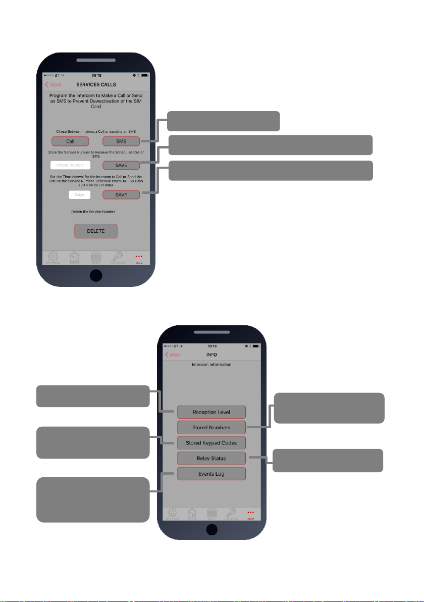
This feature is normally only used on intercoms which are
seldom used and only for SIM cards which are likely to be
de-activated by the network due to inactivity. It can be
programmed to make a chargeable outgoing call or SMS to
a number of your choice using this screen.
Enter the phone number which is to receive the call
Enter the frequency of calls (1-60 days).
TIP: This will call or SMS at the time at which the feature
was activated. So, if you set this feature up at 5pm, it will
make the service call or SMS at 5pm at the next interval.
SMS string for choosing SMS or CALL:
9999#58X# (For calls, X=2, for SMS, X=1)
SMS string for entering phone number:
9999#77XXXXXXX# (X=cell phone number) 77*# to delete.
SMS string for frequency of calls:
9999#57XX#
Check signal strength
Check stored phone
numbers
Check stored keypad
codes
Check relay status
Check who opened the
gate, when it was opened
and by what method
TIP: Iphone users will be
taken to SMS screen to
confirm message. Android
devices will auto send the
SMS.
Page 15
P a g e | 15
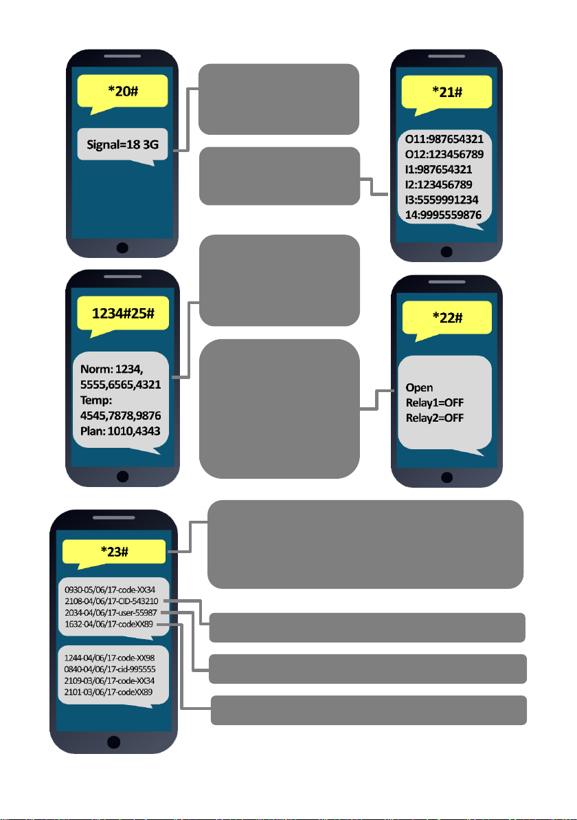
SIGNAL STRENTH
Will reply with signal range
1-31 Should be higher
than 10.
STORED NUMBERS
O=Dial out number.
I=Dial IN Caller ID number.
STORED CODES
NORM=Permanent codes.
TEMP=Temporary codes.
PLAN=Time restricted
codes.
RELAY STATUS
OPEN – Shows status of
the input terminals called
STATUS on the
intercom, can be used
with a limit switch.
Relay status shown to
check if any relay is
latched.
Last 6 digits of phone number which answered the gate
Last 6 digits of caller ID user phone number
Last 2 digits of keypad code used
ACTIVITY LOG
Use this to see who used the intercom and when. Which
pin codes were used, who used caller ID, who answered
the call.
TIP: Time and date is in international military format.
Page 16
P a g e | 16
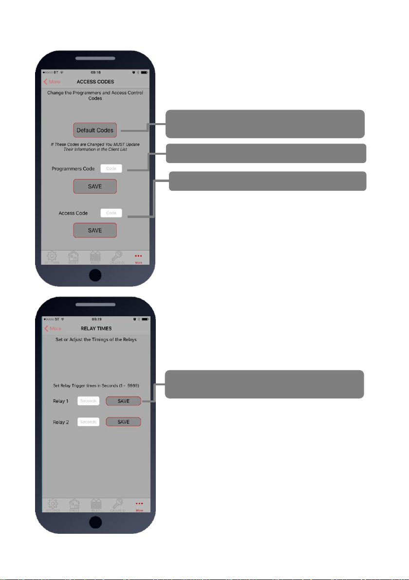
5. Pass Codes
CAUTION: Take care when changing pass codes. There are
2 levels of 4-digit code (both must be different):
1. Engineers/Programmers code (default 9999)
2. Access/user code (default 1234)
You may wish to change both from their defaults for security.
Restore the app to using default codes (does not
restore the intercom)
Enter new programmers code (default 9999)
Enter new user/access code (default 1234)
If changing default codes, then you will now need to update
the client list before you can do any further programming.
If the 1234 user access code is changed, then you will
also need to change it on the home owners app.
SMS Strings:
9999#01XXXX# (X=new programmers code)
9999#02XXXX# (X=new user access code)
6.Relay Times
Relay default trigger times are 1 second. Use this feature
to change a relay for a longer time perhaps for a magnetic
door lock or to make one relay a momentary relay and the
other a 1 hour relay for example.
SMS string for relay 1:
9999#50XXXX# (X=time in seconds, 1-9999)
SMS string for relay 2:
9999#51XXXX# (X=time in seconds, 1-9999)
Enter time in SECONDS then press SAVE to send
SMS
TIP: Iphone users will be taken to SMS screen to
confirm message. Android devices will auto send the
SMS.
Page 17
P a g e | 17
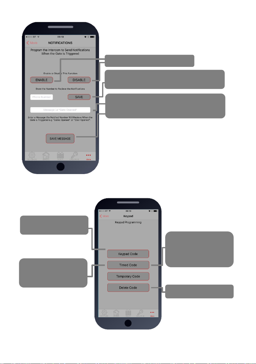
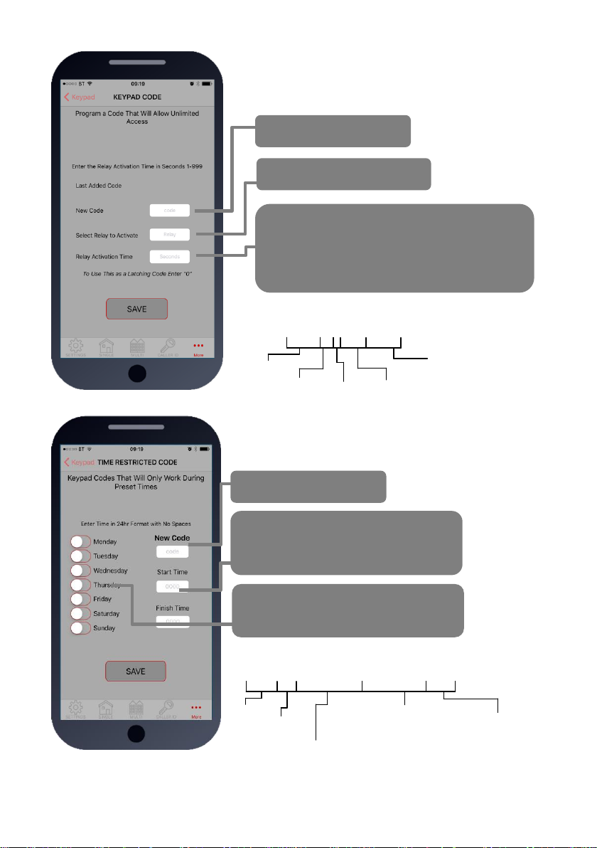
8.Keypad Programming
For Permanent 24/7
Codes
For Time Restricted
Codes (codes that work
during certain times &
days of the week
For temporary codes
(codes which auto-expire
in a pre-set time)
For deleting codes
7.Notifications
This feature is commonly used to allow one home user to
receive SMS alerts each time the INTERCOM is used to
trigger the gates and grant access.
Quick Enable / disable this feature
Enter the phone number to receive the SMS alert
and press SAVE
Enter text which you want the user to receive
when access is granted, then press SAVE
MESSAGE
SMS string for turning ON or OFF:
9999#80X# (X=2 to enable. X=1 to disable)
SMS string for entering phone number to receive notification:
9999#78XXXXXXX# (X=cell phone number) 78*# to delete.
SMS string for entering text to display:
9999#79XXXXXXX# (X is any text message you wish to
display on the phone. E.g. Gates Opened)
Page 18
P a g e | 18
Permanent Keypad Code
Stores up to 200 codes, all of which can be used to gain
access 24/7.
Time (Restricted) Code
Stores up to 20 codes which will only work during pre-set
times and days of the week. (Relay 1 only).
Enter 4 digit code
Choose Relay 1 or Relay 2
Enter activation time. (0-9999 seconds)
Use 1 second for gate trigger.
Use approx. 5 secs for magnetic locks.
Use 0 for latching or toggle code.
Use 3600 secs for 1 hour hold open on gates
SMS String for adding keypad codes:
9999#811code#time#
Pass code
Function
code
4 digit user
code
1 = Relay 1
2 = Relay 2
=SECONDS
1-9999
0 = Latching
Enter 4 digit code
Enter Start and Finish time
(Military format without any colons.
E.g. 8am = 0800. 11pm = 2300)
Select days of the week the code is to
be active.
SMS String for time restricted code:
9999#83#day,day,day#time1,time2#code#
Pass code
Function code
Enter start and end time in
24hr 4 digit format (no
colon), and separate with
comma. e.g. 0800,2300
Select days (up to 7)
3 digit format, separate
with commas.
E.g. mon,tue,wed,thu,fri
4 digit code
Page 19
P a g e | 19
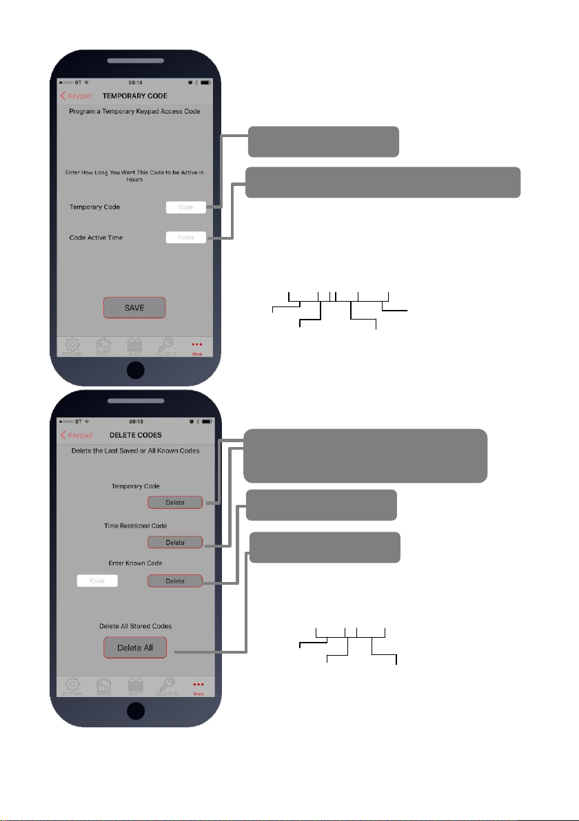
Temporary Code
Stores up to 30 codes at any time which will auto expire
after a pre-set countdown time (1-168 hours) (Relay 1
only)
Enter 4 digit code
Enter countdown time in hours (1-168 hrs)
SMS String for temporary code:
9999#82#hours#code#
Pass code
Function
code
Can be between
1-168 hours
4 digit code
Delete Codes
You can use these buttons to delete a
recently stored temp or time restricted code
(codes shown beside the delete button)
Delete any known code
Delete ALL codes
SMS String for deleting a known code:
9999#84code#
Pass code
Function
code
Code to be deleted
Deleting ALL codes: 9999#84*#
Page 20
P a g e | 20
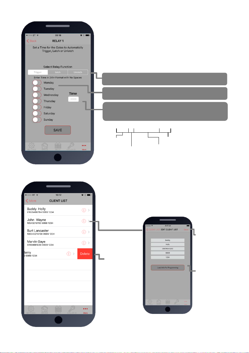
9. Auto Relay Trigger Times
Create up to 40 automatic time clock events to trigger or
latch/unlatch gates (depending on gate system setup).
For auto closing gates, send latch command at the desired
opening time, followed by a separate unlatch event to close at
the desired closing time.
For step-by-step operated gates (non auto-closing), then send
a momentary trigger command at the time required to change
the state of the gates from open to closed or closed to open.
1. Pick the type of event (momentary/latch/unlatch)
2. Choose the days
3. Enter the time in military 24hr format without colon
E.g. 8.30am = 0830. 11:10pm = 2310.
1234#1#day,day,day#time#
USER
passcode
Command:
1=trigger relay 1
2=latch relay 1
3=unlatch relay 1
4=trigger relay 2
5=latch relay 2
6=unlatch relay 2
Enter time in 24hr format (no colon)
Select days (up to 7)
3 digit format, separate with commas.
E.g. mon,tue,wed,thu,fri
10. Client list on iphone
The client list allows you to save sim phone number, customer
name and pass codes for all your installs.
On any previous install, you can load the customer and then reprogram their intercom.
Press to select Client
Press to
load details
& program
Press to
SAVE after
editing
Swipe to
delete
Page 21
P a g e | 21
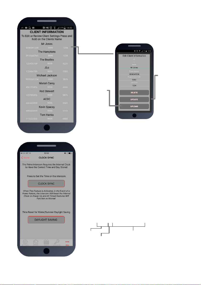
11. Clock Sync
The unit has an internal time clock counter, which reads the
time from an incoming SMS message, and uses this to
calibrate its time clock.
For power failure events, this feature allows the unit to send a
SMS to itself after a power failure.
Simply press the button and the app will send a SMS string to
the intercom storing the phone number from the SIM card
inside memory.
TIP: Use this if your area experiences regular power cuts and
your client is using timed features.
Note: Using this feature will cause the unit to be busy for 2-3
minutes after a reboot. Please be patient with programming
etc after a re-boot.
9999#86telephonenumber#
Pass code
Function code
Phone number of the SIM
card in the intercom
TIP: 9999#86*# will delete this number again
10. Client list on android
The client list allows you to save sim phone number, customer
name and pass codes for all your installs.
On any previous install, you can load the customer and then reprogram their intercom.
Press & HOLD to
select Client
Press to save
changes
Press to load
details &
begin
programming
Page 22
P a g e | 22
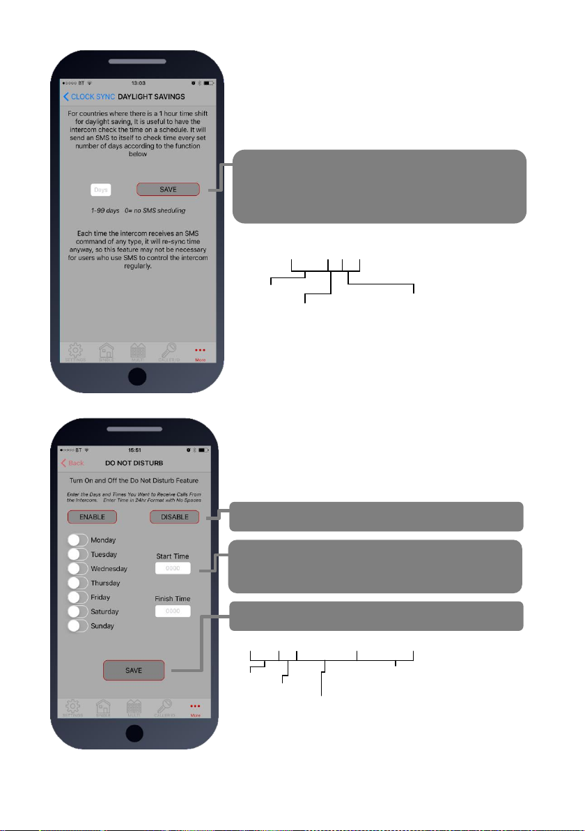
12. Do not disturb
This feature allows the push button on the intercom to be
active during pre-set times, and ignore button presses all
other times.
Use this screen to set the ACTIVE times and days for the
button.
Quick enable/disable button
Select start and finish times for the button to work
(24hr format, no spaces or colon. E.g. 8:30am = 0830
Press save to send SMS command.
9999#21#day,day,day#time1,time2#
Pass code
Function code
Enter start and end time in 24hr 4 digit
format (no colon), and separate with
comma. e.g. 0800,2300
Select days (up to 7)
3 digit format, separate with commas.
E.g. mon,tue,wed,thu,fri
To activate, enter the following code:
1234#21#ON# (change ON to OFF to disable again).
11b. Daylight Saving
For regions where there is a 1 hour time shift for daylight
saving, it can be useful to have the intercom send itself a
SMS every set number of days to re-synchronise the internal
clock. The intercom will do this anyway each time a SMS is
received.
Set the number of days between SMS message
sending (depending on carrier provider, this may be
chargeable to the customer).
9999#87??#
Pass code
Function code
1-99 days
0= no SMS sheduling
Page 23
P a g e | 23
13. Programming Proximity Cards
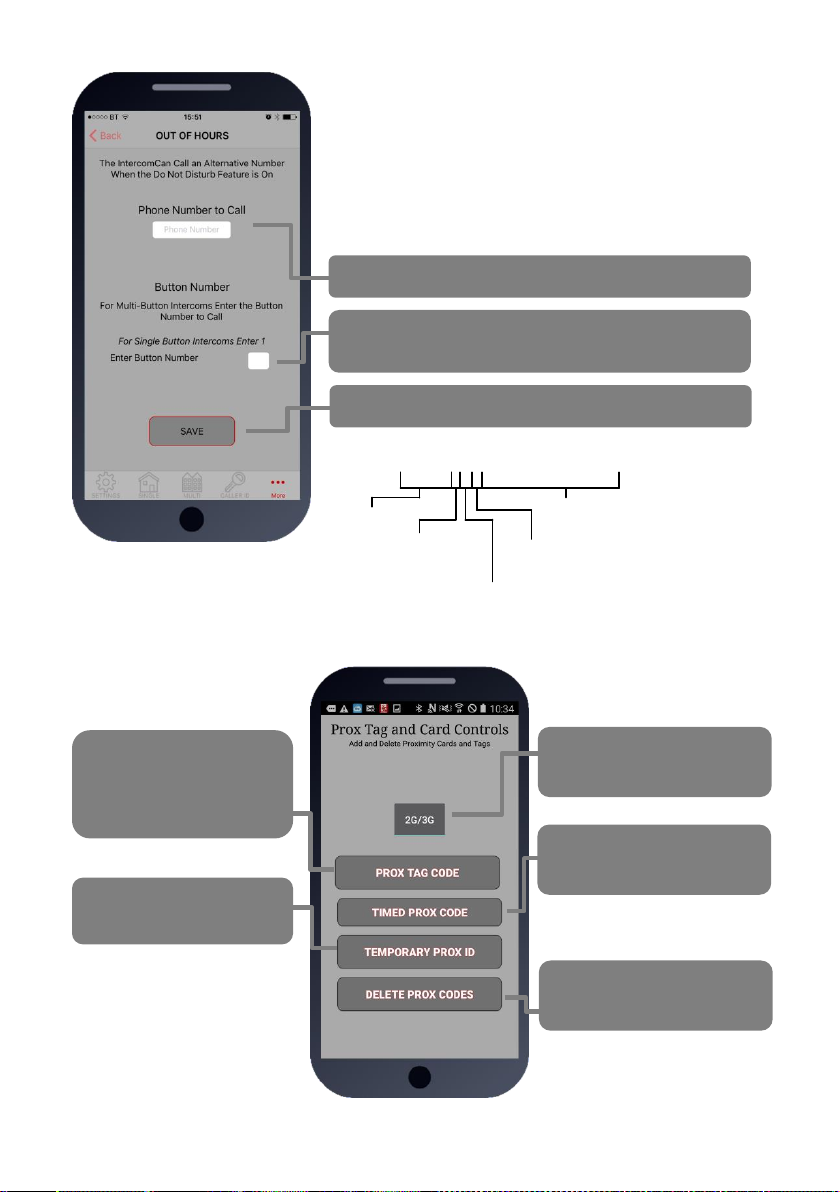
12b. After Hours / Out of Hours
If you have activated the do not disturb feature, the push
button will not call anyone after the pre-set time threshold.
However, sometimes it is useful to have the intercom call a
different number after hours. For example, in commercial
premises it can call the office phones during business hours,
and then call a security guard after hours.
1.Enter phone number to call after hours.
2. Enter button number (enter 1 for single button
system)
3. Press SAVE to confirm and send SMS
9999#211telephonenumber#
Pass code
Function code
(add number)
Data
Button number
(1-10)
Telephone number
position 1-4
Select which unit you have
(2G/3G OR 4G)
Up to 200 Prox cards or
tags (2G/3G board) or
500 cards or tags (4G
board)
Time restricted Prox cards
or tags (20)
Temporary Prox cards or
tags (30)
Delete cards or tags
Page 24
P a g e | 24
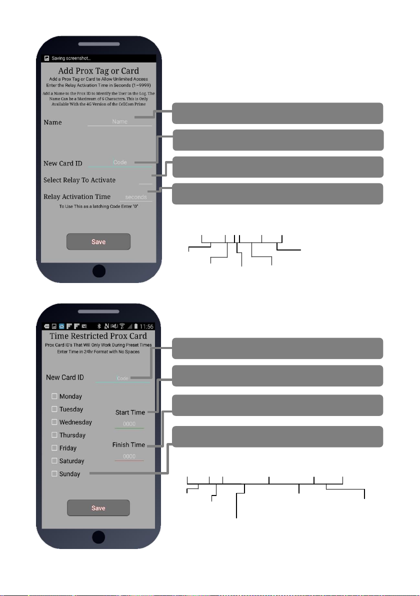
13a. Permanent Prox card/tag
Add up to 200 cards or tags for RFID access.
Note: On 4G version, you may enter a nickname for a card
which can be useful when identifying card users later. For
2G and 3G versions, ignore the name field.
Enter nickname up to 5 digits long.
Enter the 10 digit card ID number.
Select relay 1 or 2.
Enter relay activation time in seconds.
13b. Time Restricted card/tag
Add up to 20 cards or tags for time restricted access for
certain times or days of the week (relay 1 only).
1.Enter serial number of card (last 6 digits).
2.Enter start time (24hr format, no colon or spaces)
3. Enter end time (24hr format, no colon or spaces)
4. Select days of the week
SMS String for adding Prox cards/tags:
9999#611cardID#time#
Pass code
Function
code
10 digit card ID
1 = Relay 1
2 = Relay 2
=SECONDS
1-9999
0 = Latching
SMS String for time restricted card/tag:
9999#63#day,day,day#time1,time2#cardID#
Pass code
Function code
Enter start and end time in
24hr 4 digit format (no
colon), and separate with
comma. e.g. 0800,2300
Select days (up to 7)
3 digit format, separate
with commas.
E.g. mon,tue,wed,thu,fri
10 digit ID
Page 25
P a g e | 25
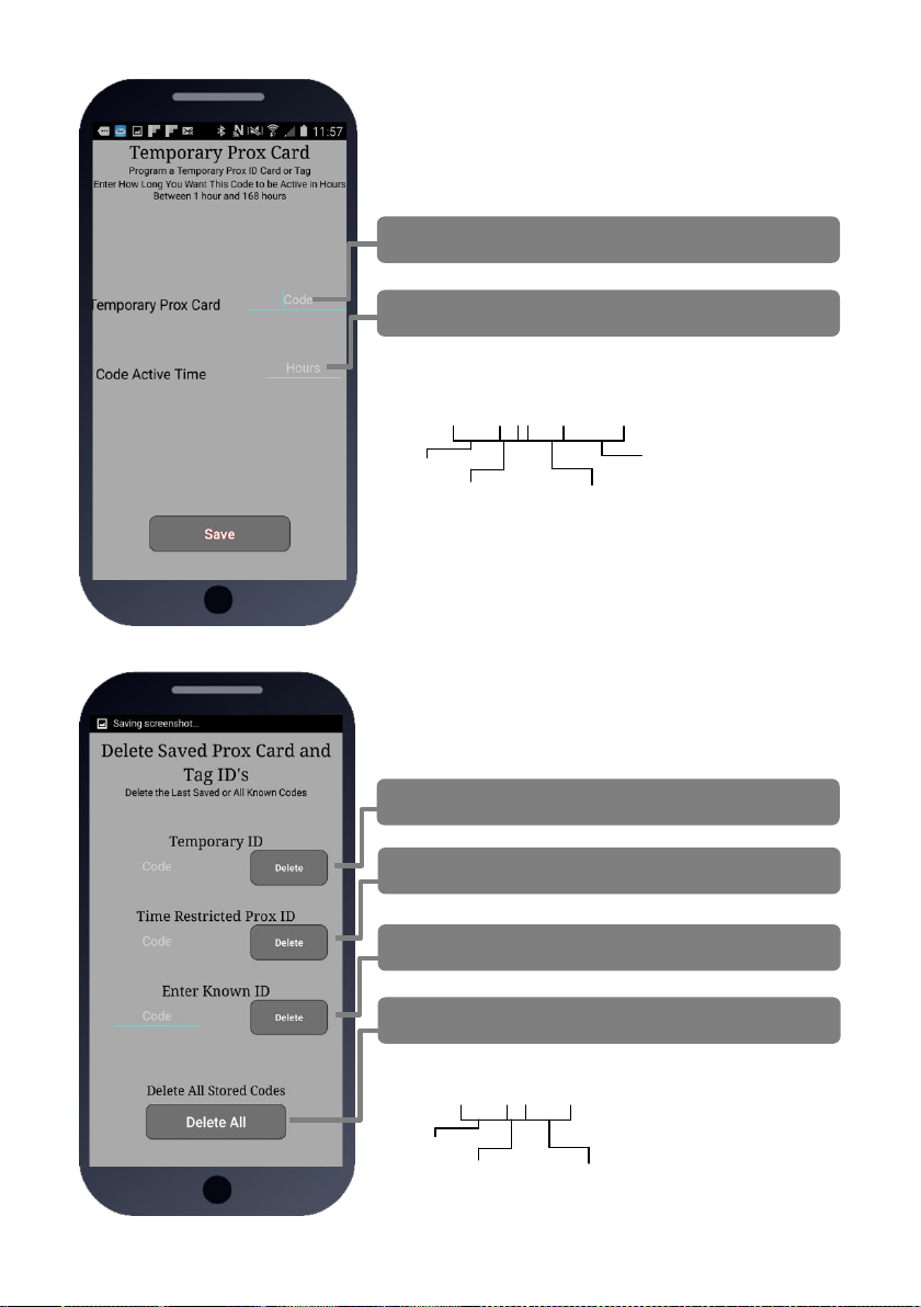
13c. Temporary card/tag
Add up to 30 cards which will only be active for a certain
time period, from 1-168 hours and then will be auto deleted
from the system.
1.Enter serial number of card.
2. Enter countdown time in hours.
13d. Deleting cards
This screen allows any known card ID to be deleted (by
serial number), and it will also show the last stored cards for
each type of card.
Delete the last stored temporary card.
Delete the last stored time restricted card.
Delete any known card ID.
Delete ALL stored cards.
SMS String for temporary card/tag:
9999#62#hours#cardID#
Pass code
Function
code
Can be between
1-168 hours
Card ID
SMS String for deleting a known code:
9999#64cardID#
Pass code
Function
code
Card ID to be deleted
Deleting ALL codes: 9999#64*#
Page 26
P a g e | 26
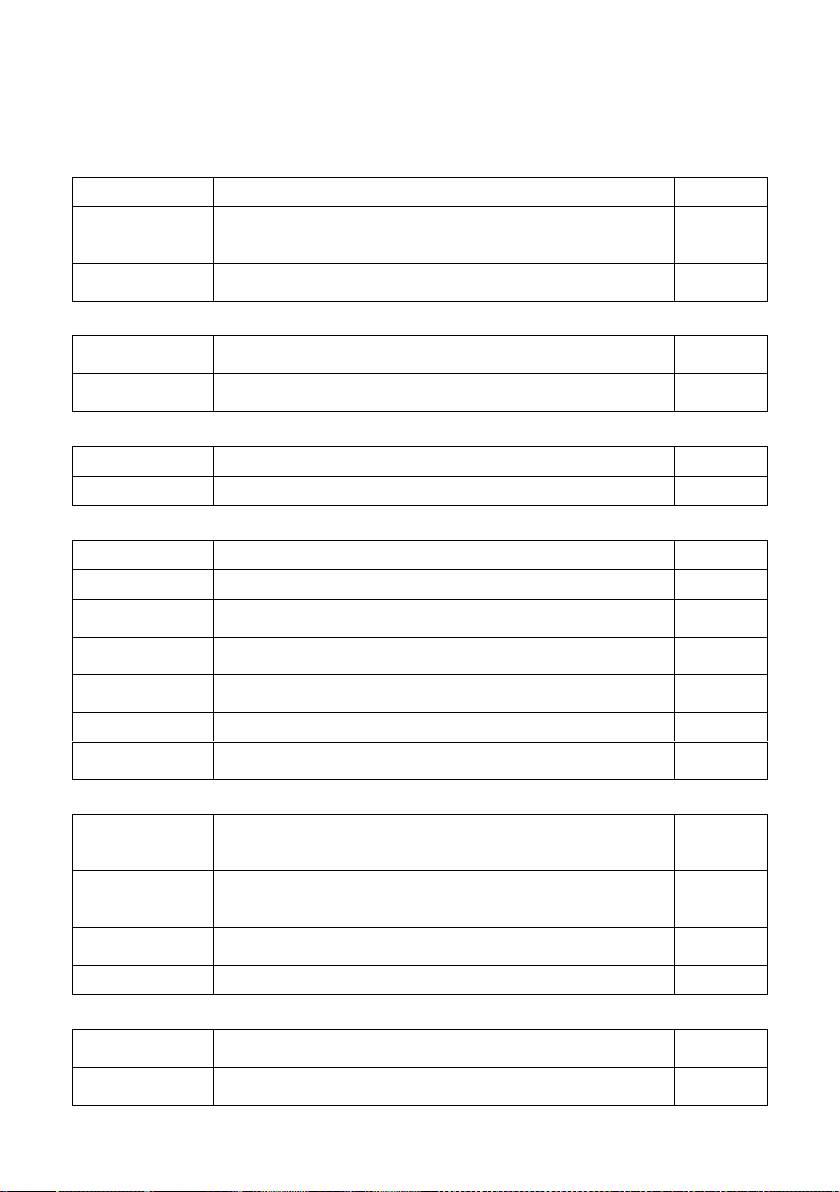
Complete list of parameters
The table below show the complete list of features.
Changing pass codes
9999#01????#
Change programming password
9999
9999#02????#
Change access control password (SMS control of relays, or
non-stored numbers can call intercom & enter code to
activate output 1).
1234
9999#03????#
Change monitoring mode password (user can call the
intercom, enter this pass code to listen in and speak)
5555
Dial out numbers
9999#1XY????#
Store dialling out numbers. (X = button number 1-9 & 0 for
button 10) (Y = number dialled 1-4) (???? = phone number)
N/A
9999#1XY*#
Delete a dial out number. (X = button number) (Y = number
position 1-4)
N/A
Volume controls
9999#3?#
Speaker volume. Where ? = 1-9. 1 = lowest, 9 = highest.
5
9999#4?#
Microphone volume. Where ? = 1-9. 1 = lowest, 9 = highest.
5
Timings
9999#50?#
Relay 1 time. ? = seconds, 1-9999
1 sec
9999#51?#
Relay 2 time. ? = seconds, 1-9999.
1 sec
9999#45??#
Calling time for first number, adjust this to avoid voicemail
picking up a call (10-99 secs)
20 secs
9999#46??#
Calling time for second number, adjust this to avoid voicemail
picking up a call (10-99 secs)
20 secs
9999#47??#
Calling time for third number, adjust this to avoid voicemail
picking up a call (10-99 secs)
20 secs
9999#53????#
Talking time. 5-9999 seconds.
60 secs
9999#55??#
Max monitoring time (for listen in mode when calling the
intercom) 00-60 mins. 00 = no limit.
10 mins
Scheduled service calls
9999#
77number#
Store a service number to receive a scheduled call or SMS
from the unit. Useful for SIM cards which are not often used
to prevent switch off by the network provider.
N/A
9999#57??#
Set the time schedule for the intercom to make a scheduled
call or SMS to the service number. 00-60 day time schedule.
00 = no call or SMS.
00
9999#58?#
Choose between making a scheduled call or scheduled SMS.
1 = SMS. 2 = call.
1
9999#77*#
Delete the stored service number
N/A
Caller ID features
9999#
72number#
Store caller ID number. Max 14 digits. Only last 6 digits
compared.
N/A
9999#
73number#
Delete caller ID number.
N/A
Page 27
P a g e | 27
9999#73*#
Delete all caller ID numbers
N/A
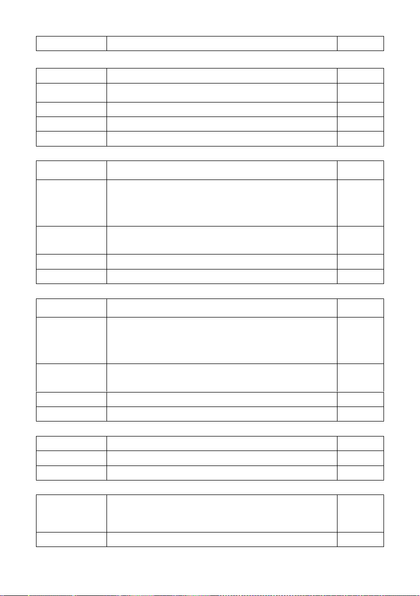
Service & diagnostic messages (no passcode required for some of these!)
*20#
Check reception level 1-31 (no passcode needed)
N/A
*21#
Check stored numbers. O = dial out number. I = dial in
number. E = end of message. (no passcode needed)
N/A
*22#
Check input status and relay status. (No passcode needed)
N/A
*23#
Sends SMS messages of the last 20 events.
N/A
1234#25#
Check stored keypad codes.
N/A
Keypad Programming
9999#
81Xcode#time#
Permanent codes - X=1 or 2 for relay 1 or 2. Code = 4-6
digits. Time = 1-9999 seconds, or 0 for latching code.
N/A
9999#
83#day,day,day
#time1,time2#
code#
Time restricted codes
Day = day of the week e.g. mon,tue,wed,thur,fri.
Time1 = start time. Time2 = end time (24 hr format, no colon.
E.g. 11:30pm = 2330. 8.30am = 0830.
Code = pin code 4-6 digits.
N/A
9999#
82#hours#
code#
Temporary codes
Hours = time to expire in hours (1-168 hours).
Code = Pin code 4-6 digit code.
N/A
9999#84code#
Delete code – Code=known code to be deleted.
N/A
9999#84*#
Delete all codes.
N/A
Prox Card/Tag Programming
9999#
61Xcode#time#
Permanent codes - X=1 or 2 for relay 1 or 2. Code = 4-6
digits. Time = 1-9999 seconds, or 0 for latching code.
N/A
9999#
63#day,day,day
#time1,time2#
code#
Time restricted codes
Day = day of the week e.g. mon,tue,wed,thur,fri.
Time1 = start time. Time2 = end time (24 hr format, no colon.
E.g. 11:30pm = 2330. 8.30am = 0830.
Code = pin code 4-6 digits.
N/A
9999#
62#hours#
code#
Temporary codes
Hours = time to expire in hours (1-168 hours).
Code = Pin code 4-6 digit code.
N/A
9999#64code#
Delete code – Code=known code to be deleted.
N/A
9999#64*#
Delete all codes.
N/A
Notifications
9999#80X#
X=1 to disable. X=2 to enable.
N/A
9999#78XXX#
X=phone number to send notifications to. (*=delete number)
N/A
9999#79text#
X=text to send to the receiving phone e.g. “gate opened”
N/A
Automatic Time Clock Trigger Times
1234#X#
day,day,day#
time#
X=1,2.3 (trigger, latch, unlatch relay 1) 4,5,6 (relay 2)
Day = days of the week (mon,tue,wed,thur,fri,sat,sun)
Time = time of day (24 hr format, no colon. E.g. 8:30am =
0830)
N/A
1234*X#
Delete ALL automatic trigger times.
N/A
Page 28
P a g e | 28
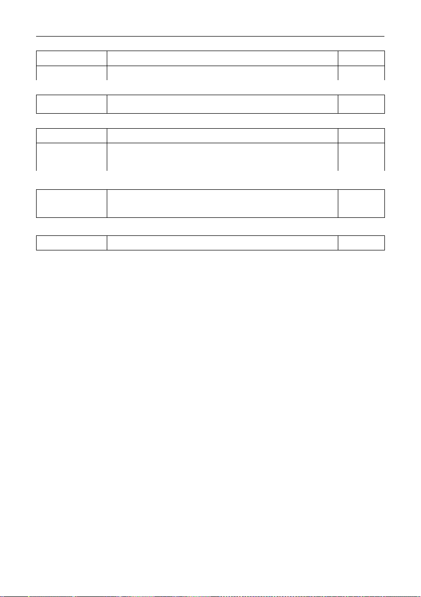
Clock Sync - Auto Time Calibration after Power Fail
9999#86XXX#
X=telephone number of SIM inside the intercom.
N/A
9999#86*#
Delete the phone number.
N/A
Summer Daylight Auto Correct
9999#87??#
?? = number of days between SMS calibration SMS should
be sent. 0 = no message sending.
N/A
Do Not Disturb (push button de-activated during set times)
1234#21#ON#
ON = activated. OFF = de-activated.
OFF
9999#
21#day,day,day
#time1,time2#
Enter all active days during which button should operate.
Enter start and end time button should operate
(24 hr format, no colon. E.G 8:30am = 0830)
N/A
Alternate Number to Call During Do Not Disturb Times.
9999#
21X????#
X = button number (1-9. Enter 1 for 1 button system. Enter 0
for button 10)
???? = Alternative phone number to call out of hours.
Restore Defaults
9999#999#
Send with passcode string to clear all programming.
N/A
Page 29

P a g e | 29
Troubleshooting
Please see faults in order of most common…
1: Not detecting network (blue light flashing 5 times in search mode, no green CPU light).
A: SIM card not detected. Power off, remove, clean sim contacts and re-insert and power on
again.
A: SIM card inserted wrong way round. Check manual for correct orientation.
A: SIM is a data sim, or has not been activated.
A: SIM has no signal in the area.
A: Antenna not connected.
A: Too many sharp bends on antenna cable.
A: Antenna mounted too low or inside metal enclosure.
A: Power cable from 24v psu is too long or too thin. Refer to manual for guidelines.
2: Not responding to SMS messages and not making outgoing calls.
A: No credit on SIM card.
A: Power cable not within spec. Refer to manual for guidelines.
3: Not triggering gates or lock when activated from phone.
A: Check relay with multi-meter.
A: Check relay 2 with multi-meter. If relay 2 works but relay 1 does not, then relay 1 may be
defective.
A: Check power cable is within specifications according to this manual.
A: Check if it works by SMS. Try latching a relay then use the status button to check if the relay is
latched. If that works, problem could be the phone being used, or low signal strength at the
intercom.
3: Poor sound or buzzing
A: Ensure there is no spare antenna cable inside the call point with the intercom. Straighten
excess cable.
A: Install the antenna further away from the intercom.
A: Check the power cable is within guidelines of this manual.
4: Home owner app not working correctly
A: Check the settings on the app has the intercom SIM number and pass codes entered correctly.
Page 30
P a g e | 30
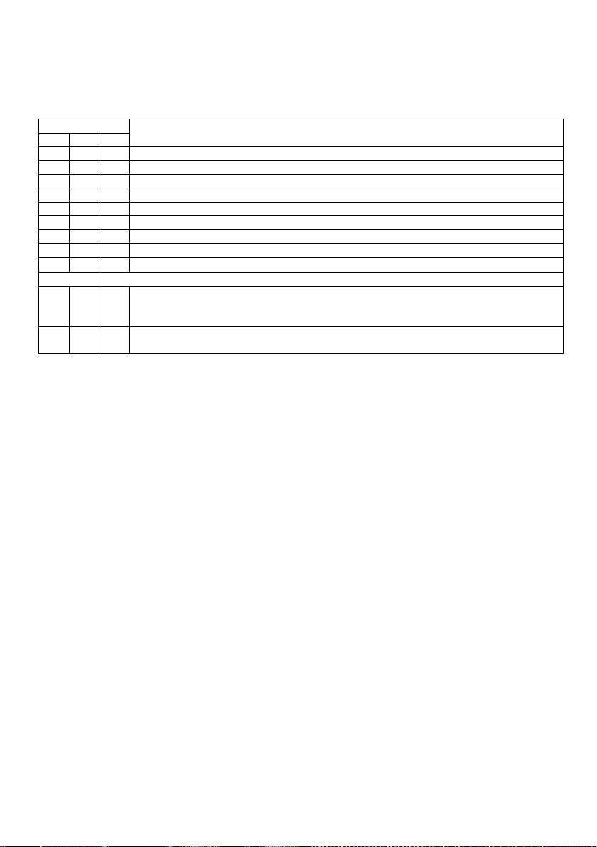
Change History
Key:
P = Panel version H = Hardware PCB version S = Software version
Version
Reason for change
P H S 1 1 1 First version.
1 2 1
Power chip upgraded to work on 24v dc (24v adaptor in kits).
1 2 2
Software feature added for call log to show last 25 caller ID calls.
1 3 2
Main capacitor, regulator & diode upgraded for 24v ac.
1 4 2
Micro Sim Holder and complete board respin
1 4 3
Caller ID fix for international + symbol. (October 2016)
1 5 4
PRIME model, new firmware plus larger flash storage. (November 2016)
1 6 4
SMA connection directly on the board, micro sim and 24v PSU (July 2017)
Prime6 begins here
1 1 1
-First version, with slave keypad connections.
-Prox option.
-Architectural panels have call button in centre.
1 2 1
-Nano SIM, larger capacitors on PCB for CAT5 power cable, surge protection
added.
Page 31

P a g e | 31
EU-RED Declaration of Conformity
Manufacturer: Advanced Electronic Solutions Global Ltd
Address: Unit 4C, Kilcronagh Business Park, Cookstown, Co Tyrone, BT809HJ, United Kingdom
We/I declare, that the following equipment (GSM Cellular Intercom System), part numbers:
Multiple Model kit part numbers: GSM-5AB, GSM-5ABK, GSM-5HB, GSM-5HBK, GSM-5IMP, GSM-5IMPK, GSM-FB, GSM-5FBK.
Complies with the following essential requirements for 2014/53/EU:
ETSI draft EN 301 489-1 V2.1.1 (2017-02) (Electromagnetic compatibility)
ETSI draft EN 301 489-52 (2016-11) (Electromagnetic compatibility, specific to cellular)
(WCDMA Band 1, Band 8, GSM 900 / 1800).
Test report number LCS170721023AE
ETSI EN 301 511 V12.5.1 (2017-03) (3.2 of directive 2014/53/EU)
ETSI TS 151 010-1 V12.8.0 (2016-05) (Digital cellular telecoms compliance)
Test report number LCS170721025AE
ETSI EN 301 908-1 V11.1.1 (2016-07) (IMT Cellular networks, 3.2 of directive 2014/53/EU)
ETSI EN 301 908-2 V11.1.1 (2016-07) (CDMA spread / UTRA FDD)
Test report number LCS170721026AE
EN 62311 :2008 (Electromagnetic safety and human exposure)
Test report number: LCS170721027AE
EN 60950-1, (A1, A11, A12, A2)
EN 62311
The notified body is: Telefication BV (CAB number 0560).
This declaration is issued under the sole responsibility of the manufacturer.
Signed by:
Paul Creighton, Managing Director. Date: 1-Feb-2018
Australia / New Zealand Approvals:
This product is not a complete product until fully installed. It is therefore considered a component part of an overall system. The
installer is responsible to check that the end installation complies with local regulatory requirements. This equipment forms part of
a “fixed installation”.
The manufacturer cannot legally offer technical support to non-qualified gate or door installers. End users should employ the
services of a professional install company to commission or support this product!
0560
Page 32

P a g e | 32
 Loading...