

Page 1

P a g e | 1
Installation & User Manual For
GSM Cellular Gate opener and GSM alarm signalling device.
Page 2

P a g e | 2
Contents
Overview of system
…………….Pg 3
Site Survey
…………….Pg 3
SIM card
…………….Pg 3
Power
…………….Pg 3
Inserting the SIM card
…………….Pg 4
Connections on the GSM Controller
…………….Pg 4
Output Connections example
…………….Pg 4
Notification Feature
…………….Pg 5
Powering Up
…………….Pg 5
Programming
…………….Pg 6
Programming as an Access Control Device
…………….Pg 6
Internal Clock Function
…………….Pg 7
Winter / Summer Daylight Saving
…………….Pg 7
Set Automatic Triggering Times
…………….Pg 7
Delete all Automatic Triggering Times
…………….Pg 8
Notification Number
…………….Pg 8
Programming as an Alarm Dialling Device
…………….Pg 8
Complete List of Parameters
…………….Pg 8
Controlling Relays when used as Alarm
…………….Pg 10
Control by SMS
…………….Pg 10
Check Door / Gate Status
…………….Pg 10
Setting up the free App
…………….Pg 10
Using the Android App
…………….Pg 12
Using the Iphone App
…………….Pg 15
Troubleshooting
…………….Pg 18
Change History
…………….Pg 19
Page 3
P a g e | 3
Overview of System
Please read this entire manual before attempting to install this system.
This system should only be installed by a professional automatic gate installer or access control
specialist dealer.
It is recommended that the system be set up, configured, commissioned and tested on a
workshop bench before taken to site for installation.
Site Survey
Before installing this system, you need to be sure that there is good mobile GSM cell coverage in
the area it is to be installed. It is recommended that you conduct a site survey, and check
reception on the site for a GSM network. If reception is poor in the area, then this system is not
recommended.
SIM Card
You will need a SIM card in order to use this system. It should be a regular voice and SMS text
SIM card. Do not use a data only SIM, as this is only for tablets and will not work in the unit.
Power
TIP: Most technical calls received are due to installers using CAT5 or alarm cable to power
the unit. Neither are rated to carry enough power (2 amp peak). Please use following
cable…
Up to 2 metres (6 feet) – Use minimum 0.5mm2 (18 gauge)
Up to 4 metres (12 feet) – Use minimum 0.75mm2 (16 gauge)
Up to 8 metres (24 feet) – Use minimum 1.0mm2 (14 gauge)
Using insufficient power cable thickness will cause excessive stress on electronic components,
and therefore void the manufacturer’s warranty.
To avoid such problems it is recommended (and is good practice) to locate the power supply as
close to the device as possible. This avoids power cable noise and interference and enhances the
lifetime of the product.
1) Ensure the SIM has calling credit, and can make and
receive calls on a mobile cell phone.
2) Check that the SIM is not locked to a phone and can be
used in other devices.
3) Check that the SIM does not have a PIN code request.
4) Disable voicemail service on the SIM.
4) You are now ready to begin programming.
Page 4
P a g e | 4
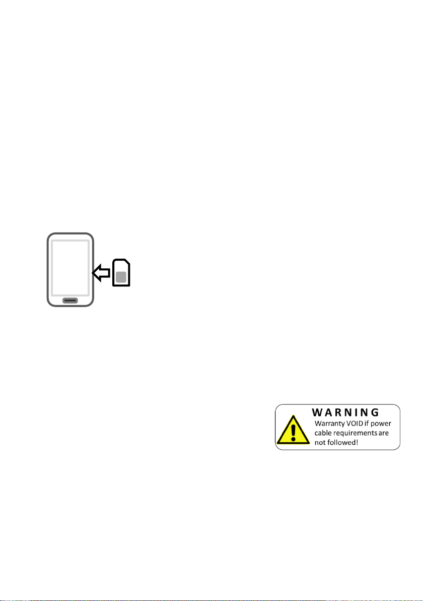
Inserting the SIM card
Note: This unit is a quadband 2G product. Ensure it is operating on a network which can provide
2G at 850/900/1800/1900 MHz.
Micro SIM
Insert this
way!
1) Ensure the power is OFF
2) Slide the micro-SIM in face down, with the chamfer facing out as shown above until it
clicks into place.
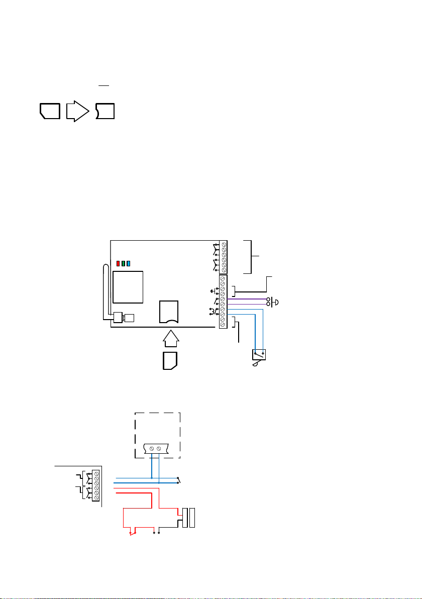
Connections on the GSM Controller
N/C
COM
N/O
GSM
modem
N/C
COM
N/O
Out 1
Out 2
eg
12-24ac/dc
Optional input
trigger for alarm
device function
Optional exit
button, triggers
output 1 for
programmed
time.
12-24v ac/dc
Optional gate
position limit switch
Relay
outputs
Signal LED
CPU
Power
Micro SIM
Insert this
way!
Output Connections Example
N/C
COM
N/O
N/C
COM
N/O
Out 1
Out 2
Start
Common
Gate motor controller
12v dc
Separate
PSU
+
+
-
-
Other exit
device, e.g.
keypad
Magnetic
Lock
Other exit
device, e.g.
keypad
This example shows relay 2 connected
to a gate motor controller for vehicle
gates, and output 1 connected to a
magnetic lock for a door or pedestrian
gate.
Please ensure the SIM card is a 2G compatible Micro SIM card. The
SIM may also be 3G and 4G capable as well, as long as both the
SIM and the network also support 2G. Do not use a SIM card for a
tablet, as these only support data, and do not support voice and
SMS. You simply require a mobile phone type SIM card.
Page 5
P a g e | 5
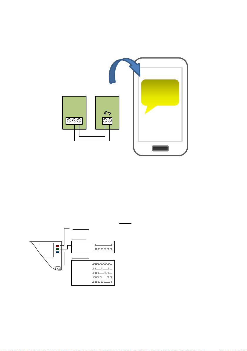
Alternative Keypad Wiring for Notification Feature
The Cell Box Switch has an additional feature which sends an SMS to a master user when the
GSM unit triggers it’s outputs. So if the user wants to know when an external device such as a
keypad is triggered, then wire a keypad output to egress input of the GSM as shown…
When the egress is triggered, the GSM unit’s output 1 will be triggered and if the 78 feature is
programmed, the unit will send an SMS.
Powering Up
Perform a final check of wiring, making sure that the power supply is no more than the absolute
maximum is no more than 26v AC and ensure the antenna is connected before switching on the
power. Once the power is switched on, the power LED should illuminate.
Power LED
CPU LED
Signal LED
Searching
1 bar signal
2 bars signal
3 bars signal
4 bars signal
System booted
Booting
GSM
modem
TIPS:
My GSM LED is still searching…
-Check the SIM card is registered and can make a
call in a phone.
-Check the SIM card is seated correctly. Power off,
clean the contacts on the SIM and the GSM unit,
and reinsert the SIM.
-Check power cable distance and thickness.
-Increase antenna height.
-Change network.
-Move antenna away from metal objects or
overhanging shrubs.
-Fit a high gain antenna.
My gates
opened!
eg
Output1
N/O
COM
N/C
Keypad GSM unit
Page 6
P a g e | 6
Programming
TIP: The GSM unit programming is by sending SMS text messages to the unit from a phone.
Check Reception
TIP: If reception levels are low, take action now! Either increase the height of the antenna to
improve reception or request a higher gain antenna from your distributor or change to another
network which may have better coverage.
Programming as a Gate / Door Access control Device
The unit is able to store up to 100 telephone numbers which can call the intercom and trigger the
relay automatically with caller ID. Programing text messages must start with a pass code string,
followed by a command, followed by data, and each command is separated in the SMS by #.
Enter the phone numbers you require to have access in SMs strings as follows…
9999#72telephonenumber#
Pass code
Function code
(add number)
Data
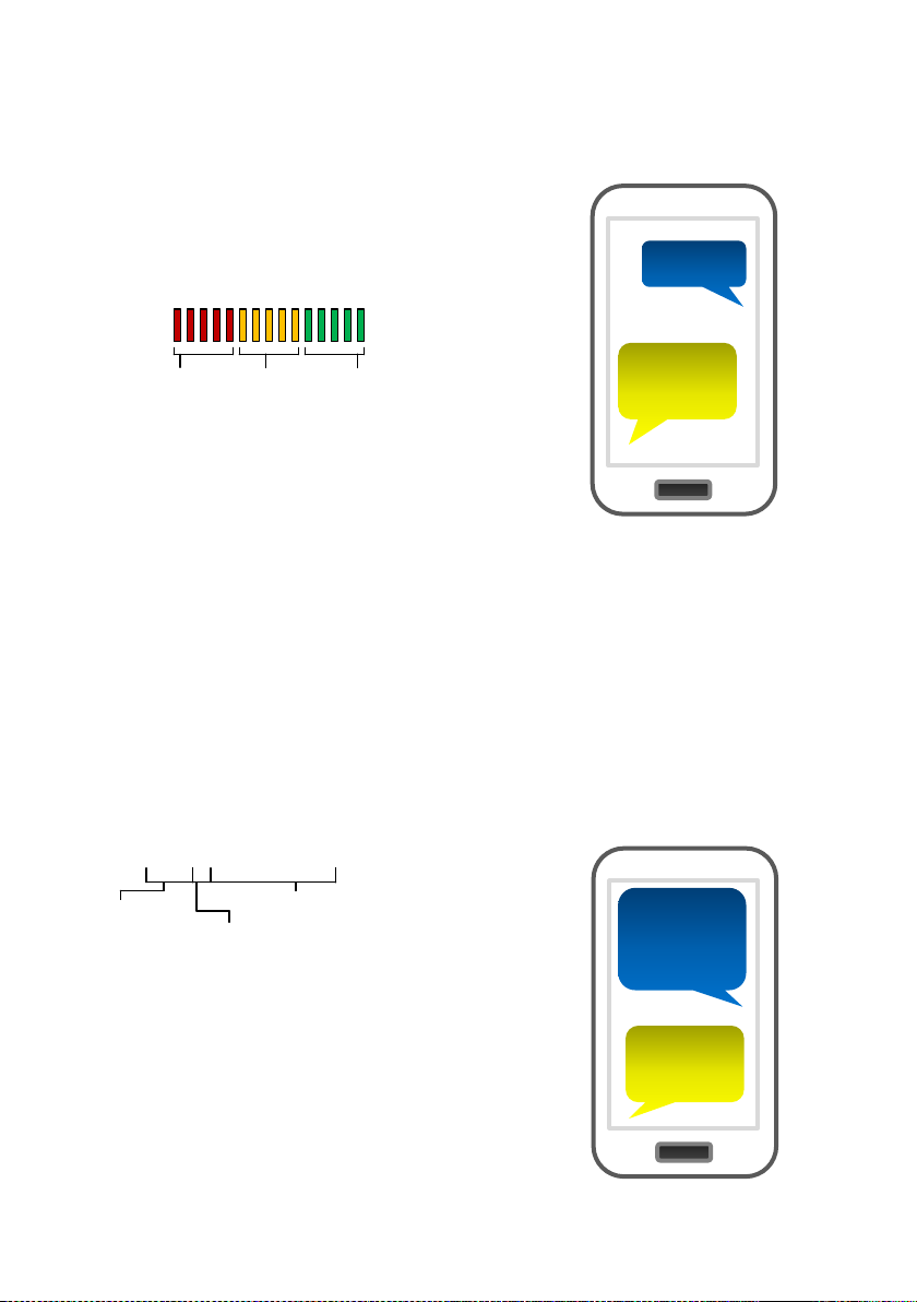
Send the SMS *20# as shown, to the SIM card
number of the intercom. The unit should reply with a
reception level between 1 and 31.
*20#
Signal
level = 19
1-12
Poor
13-20
Medium
21-31
Good
Note: Reception levels below 14 can give problems with the
relay operation
9999#7209
87654321#
72098765
4321 OK
Tip: Up to 4 telephone numbers can be sent together in the
same SMS message. Simply separate each with 72 as
shown...
9999#72telephonenumber#72telephonenumber#
72telephonenumber#72telephonenumber#
Page 7

P a g e | 7
Internal Clock (Function 86)
The PRIME model has many additional features which require the intercom to have the current
time and day stored. Each time the intercom receives a SMS, it will use the time and date from the
incoming message to re-calibrate its internal time clock. In the event of a power failure, the time
will be lost, however the intercom can send a SMS to itself after rebooting. To activate this
feature, enter the following code…
9999#86telephonenumber#
Pass code
Function code
Phone number of the SIM
card in the intercom
TIP: 9999#86*# will delete this number again
Winter/Summer Daylight Saving (Function 87)
For countries where there is a 1 hour time shift for daylight saving, It is useful to have the intercom
check the time on a schedule. It will send an SMS to itself to check time every set number of days
according to the function below..
9999#87??#
Pass code
Function code
1-99 days
0= no SMS sheduling
Set Automatic Triggering times
This feature is useful to automatically trigger electric gates at pre-set times of the day or night. For
gates not set on “auto-closing”, this can be used to have opened and closing times with
momentary triggers. For gates on “auto-closing”, this feature can be used with latching control,
again to hold gates open during certain times.
1234#1#day,day,day#time1#
USER
passcode
Command:
1=trigger relay 1
2=latch relay 1
3=unlatch relay 1
4=trigger relay 2
5=latch relay 2
6=unlatch relay 2
Enter time in 24hr format (no colon)
Select days (up to 7)
3 digit format, separate with commas.
E.g. mon,tue,wed,thu,fri
Example:
For gates on step-by-step operation, to automatically close every night at 10pm send SMS:
1234#1#sun,mon,tue,wed,thu,fri,sat#2200#
For gates on automatic closing, to hold open between 8am and 7pm, send SMS:
1234#2#sun,mon,tue,wed,thu,fri,sat#0800# and then a second SMS:
1234#3#sun,mon,tue,wed,thu,fri,sat#1900#
Note: Up to 40 events can be stored.
Note: Activating this feature will cause
the unit to be busy for 2-3 minutes after
boot up. Please be patient with the unit
while it re-configures.
Note: Each time the intercom receives an SMS
command of any type, it will re-sync time
anyway, so this feature may not be necessary
for users who use SMS to control the intercom
regularly.
Page 8

P a g e | 8
Delete ALL Automatic Triggering times
1234*#
Notification Number
This feature will send a SMS notification to a master user phone number every time the intercom
is used to grant access. It will send a SMS any time a relay is activated.
To use this feature firstly turn the function on:
9999#802# (change 2 to 1 to disable again).
Now you must store the phone number which is to receive the notification:
9999#78number#
Now you may store a customised SMS content, which will be sent to the stored number:
9999#79enter any text here#
For example, you may wish to store the following message “My Gates Triggered”, or “Gates
Opened”.
Programming as an Alarm Dialling Device
This advanced GSM unit is also able to be used as a GSM alarm device. If the input terminals are
triggered with a closing connection, the device will call up to 4 phone numbers in sequence.
9999#111telephonenumber#
Pass code
Function code
(add number)
Data
Telephone number
position 1-4
9999#111telephonenumber#112telephonenumber#113telephonenumber#114telephonenumber#
GSM unit complete list of parameters
The table below show the complete list of features in the cellular part of the intercom.
Programming messages below must begin with 9999# (assuming 9999 is still the
programming passcode)…
Changing pass codes
01????#
Change programming password
9999
02????#
Change access control password (SMS control of relays, or
non-stored numbers can call intercom & enter code to activate
output 1).
1234
Tip: Up to 4 telephone numbers can be dialled in
the event of an alarm. Simply change the number
position digit as shown…
Page 9

P a g e | 9
Dial out numbers
1XY????#
Store dialling out numbers. (X = button number 1-9 & 0 for
button 10) (Y = number dialled 1-4) (???? = phone number)
N/A
1XY*#
Delete a dial out number. (X = button number) (Y = number
position 1-4)
N/A
Timings
50?#
Relay 1 time. ? = seconds, 1-9999
1 sec
51?#
Relay 2 time. ? = seconds, 1-9999.
1 sec
45??#
Calling time for first number, adjust this to avoid voicemail
picking up a call (10-99 secs)
20 secs
46??#
Calling time for second number, adjust this to avoid voicemail
picking up a call (10-99 secs)
20 secs
47??#
Calling time for third number, adjust this to avoid voicemail
picking up a call (10-99 secs)
20 secs
Scheduled service calls
77number#
Store a service number to receive a scheduled call or SMS
from the unit. Useful for SIM cards which are not often used to
prevent switch off by the network provider.
N/A
57??#
Set the time schedule for the intercom to make a scheduled
call or SMS to the service number. 00-60 day time schedule.
00 = no call or SMS.
00
58?#
Choose between making a scheduled call or scheduled SMS.
1 = SMS. 2 = call.
1
77*#
Delete the stored service number
N/A
Notification Number
78number#
Store a master user, who will receive a SMS notification from
the intercom each time any of the output relays are triggered.
N/A
79text#
Where “text” is the content of the message to be sent. E.g.
“Gates Opened, or Door Opened”. This will be sent on closing
of any output relay.
N/A
80?#
When ? = 1, this function is disabled. Set to 2 to enable.
N/A
Caller ID features
72number#
Store caller ID number. Max 14 digits. Only last 6 digits
compared.
N/A
73number#
Delete caller ID number.
N/A
73*#
Delete all caller ID numbers
N/A
Service & diagnostic messages (no passcode required for these!)
*20#
Check reception level 1-31 (no passcode needed)
N/A
*21#
Check stored numbers. O = dial out number. I = dial in
number. E = end of message. (no passcode needed)
N/A
*22#
Check input status and relay status. (No passcode needed)
N/A
Page 10

P a g e | 10
*23#
Call log of last 20 Caller ID numbers
N/A
Restore Defaults
999#
Send with passcode string to clear all programming.
N/A
Controlling Relays when used as Alarm Dialler
If the alarm input is used to trigger the unit and call a phone, the user can answer the call and
control the relays with DTMF touch tones on their phone as follows..
Control by SMS
This device allows the user to send SMS commands to control the relays as follows…
1234#1# - Relay 1 momentary trigger.
1234#2# - Relay 1 latch ON or hold ON.
1234#3# - Relay 1 unlatch or switch OFF.
1234#4# - Relay 2 momentary trigger.
1234#5# - Relay 2 latch ON or hold ON.
1234#6# - Relay 2 unlatch or switch OFF.
Check if door or gate is open or closed
1
2
3
4
5
6
7 8 9
0 * #
Relay 1
Press 1 to momentary trigger
Press 2 to Latch or hold open
Press 3 to unlatch or close.
Send the SMS as shown, and the unit will reply showing the status
of the input limit switch (if used), and the relay..
This example shows that the input sensor is in OPEN state. Relay 1
is OFF and Relay 2 is latched ON.
TIP: If there is not a physical limit switch fitted to the door or gate,
then the status input will always show OPEN.
*22#
OPEN,
Relay 1=
OFF,
Relay 2 =
ON
Relay 2
Press 4 to momentary trigger
Press 5 to Latch or hold open
Press 6 to unlatch or close
Page 11

P a g e | 11
Setting up the Free App on Android & Iphone
Android and Iphone users can download an optional app
called CellcomPRIME. This makes the procedure of adding
and deleting keypad codes easy, as well as other control
features.
Android Setup
Apple Setup
1. Install and launch the
app. Press SETTINGS as
shown.
2. Press the PHONE
NUMBER button.
3. Enter the phone
number of the intercom
SIM card.
Note: If the default engineers code or user code have been changed from their defaults, then
please change as required in the relevant section above.
IMPORTANT: On using the app, if you receive an error message stating “Command
Failed”, go to Settings/Application Manager/Permissions, and turn on all permissions for
the app.
Now you should be ready to use the app.
Page 12

P a g e | 12
Using the App on Android
KEYPAD SETTINGS
(Not used on this device)
OPEN GATES
Press to trigger the
relay (speed dials
intercom for output 1
and sends SMS to
intercom for output 2)
UNLATCH /
UNHOLD
Press to release a
latched relay (allow
gates to close)
LATCH / HOLD
OPEN
Press to hold ON the
relay
Press to change
controls from relay 1
to relay 2 (useful for
pedestrian gates)
HOME / TIME
SETTINGS
Features such as
auto triggering, do
not disturb, activity
log.
NOTIFICATION
OPTION
Press to setup SMS
notifications when
gates are triggered.
Page 13

P a g e | 13
Automatic Triggering Times
Notification Feature
This feature is for automatic gate systems which
are not in automatic closing mode, and are in stepby-step mode. I.e. When triggered they open and
stay open until triggered again. You can use this
feature to automatically trigger gates to perhaps
open every morning at a pre-set time, or close
every night at a pre-set time.
TIP: Enter times in 24 hour format without any
colon. E.g. 10pm should be entered as 2200, select
the days and press SAVE.
Can be used to send a SMS notification to a
master user, each time someone calls the
device and access is granted.
Toggle the feature on firstly.
Then enter a phone number which will
receive the notifications.
Lastly enter a message like “Gates
Opened”
Page 14

P a g e | 14
Status Sub-Menu
Check stored
numbers – Will
send SMS reply
with O for dial
out numbers
and I for dial in
(caller ID
access
numbers).
Check signal
strength on your
intercom. Level
1-31. Must be
above 14 for
successful
operation.
Check last 20
users who
triggered gates,
including date
and time (date
is international
format
(DD/MM/YYYY)
Check the state
of both relays
(ON or OFF).
ON = latched
open state.
Check status of
gate limit switch
(if fitted).
Page 15

P a g e | 15
Using the app on Iphone
OPEN GATES
Press to trigger the
relay (speed dials
intercom for output 1
and sends SMS to
intercom for output 2)
LATCH / HOLD
OPEN
Press to hold ON the
relay
TIME SETTINGS
Features such as auto triggering, do not
disturb, activity log, set clock etc.
Press to change
controls from relay 1
to relay 2 (useful for
pedestrian gates)
UNLATCH /
UNHOLD
Press to release a
latched relay (allow
gates to close)
NOTIFICATION
OPTION
Press to setup SMS
notifications when
gates are triggered.
KEYPAD SETTINGS
(Not used on this
device)
Page 16

P a g e | 16
Automatic Triggering Times
Notification Feature
This feature is for automatic gate systems
which are not in automatic closing mode,
and are in step-by-step mode. I.e. When
triggered they open and stay open until
triggered again. You can use this feature
to automatically trigger gates to perhaps
open every morning at a pre-set time, or
close every night at a pre-set time.
TIP: Enter times in 24 hour format without
any colon. E.g. 10pm should be entered as
2200, select the days and press SAVE.
Can be used to send a SMS notification to a
master user, each time someone calls the
device and access is granted.
Toggle the feature on firstly.
Then enter a phone number which will
receive the notifications.
Lastly enter a message like “Gates
Opened”
Page 17

P a g e | 17
Status Sub-Menu
Check stored
numbers – Will
send SMS reply
with O for dial
out numbers
and I for dial in
(caller ID
access
numbers).
Check signal
strength on your
intercom. Level
1-31. Must be
above 14 for
successful
operation.
Check last 20
users who
triggered gates,
including date
and time (date
is international
format
(DD/MM/YYYY)
Check the state
of both relays
(ON or OFF).
ON = latched
open state.
Check status of
gate limit switch
(if fitted).
Page 18

P a g e | 18
Troubleshooting guide
Q. The unit will not power up. No LEDs on.
A. Check alarm or CAT5 cable has not been used to power the device. If it has, the warranty will
be void. Please remove and replace as per instructions.
Q. The unit powers up but is not showing network reception or will not respond to SMS.
A. This means the unit is not able to detect the network for some reason.
-Check the SIM card is activated and has calling credit.
-Power off the unit, remove the SIM and check it in a mobile phone to verify it can make a call.
-Check the SIM does not ask for a PIN code when put in a phone. If it does, then disable the PIN
code request.
-Check the SIM is a standard voice SIM and not a data only SIM for a tablet.
-Check the reception is strong. Poor reception is not sufficient.
- Check alarm or CAT5 cable has not been used to power the device. If it has, the warranty will be
void. Please remove and replace as per instructions.
-Power off, remove the SIM, use fine sand paper or a sharp object to lightly clean the SIM pads
and contacts on the GSM unit. Gently bend the contacts upwards so that they make better contact
with the SIM and try again.
Q. The caller ID part does not work.
A. Be sure to program the caller ID part under 72 feature. If your number is a private or number
withheld, then it will not work.
-Even if you have already programmed a number to receive a call from the device, if you also
want that number to have caller ID access, it must be programmed under the 72 feature also.
-Ensure the number is entered as you would normally dial it from another phone.
Q. The keys do not work when the device calls a phone.
A. Check if you can hear the relay clicking at the gate when the keys are pressed during a call. If it
can be heard, then the system is working, check wiring between the relay and the lock or gate
panel. If the relays do not make a clicking sound, then check this feature on a different mobile cell
phone or landline. If it works on a different phone, check the settings on the phone in question
under DTMF tones.
Failure of DTMF tones to operate correctly is also a symptom of low reception. Check steps above
on improving reception. Try pressing the buttons longer when attempting to activate the gates or
door.
Also check that the relays are not already latched with the *22# command. If they are latched,
they need unlatched before the trigger keys will work.
Q. The system was operating the gates fine, but now it will not trigger the gates.
Most of the time, this is cause by the user accidentally latching the relay. This latches the output
relay permanently on. Send the intercom the following SMS *22#. The device should reply with a
message detailing the relay status.. If it has been latched, then the message will state “the relay is
ON”. In this case refer to the user guide to read how to unlatch it again.
Q. The unit no longer calls out to phones but I can make a call to it from my phone.
A – Check there is balance on the SIM card.
A – Switch off the power, remove the SIM, put it into a phone, and check that a call can be made
from a phone. This will verify if the SIM is still working and in service.
Page 19

P a g e | 19
Change History
Key:
H = Hardware PCB version S = Software version
Reason for change
H
S
1 1 First version.
2 1 Power chip upgraded to work on 24v dc (24v adaptor in kits).
2 2 Software feature added for call log to show last 25 caller ID calls.
3 2 Main capacitor, regulator & diode upgraded for 24v dc.
4 2 24v ac power board added to allow 24v ac power input
4 6 PRIME model, new firmware, larger flash storage, Micro SIM holder, antenna
connects direct to PCBA, Red colour PCBA, all black model design.
Page 20

P a g e | 20
 Loading...