

Page 1
Part No. 40-7707 Rev. 3a 10/23/2017
AES 7707 RF Subscriber
Installation, Operation and Programming
Manual
AES Corporation
285 Newbury Street
Peabody, MA 01960 USA
Tel (978) 535-7310 • Fax (978) 535-7313
www.aes-corp.com
Copyright © 2017 AES Corp. All Rights Reserved
Page 2

AES 7707 RF Subscriber 2
Part No. 40-7707 Rev. 3a 10/23/2017
This page deliberately left blank
Page 3

AES 7707 RF Subscriber 3
Part No. 40-7707 Rev. 3a 10/23/2017
Table of Contents
1. Safety Considerations .......................................................................................................... 7
2. Technical Specifications ....................................................................................................... 8
3. Pre-Installation .................................................................................................................... 9
3.1 Equipment List ................................................................................................................9
3.2 Mounting ........................................................................................................................9
Subscriber Location ...................................................................................................9
Antenna Selection and Location ...............................................................................9
3.3 Requirements .................................................................................................................9
Environmental ...........................................................................................................9
Electrical Supply ......................................................................................................10
Wiring Specifications ...............................................................................................10
Power Options ........................................................................................................10
Battery Size .............................................................................................................10
4. Installation ......................................................................................................................... 11
4.1 7707 Installation ...........................................................................................................11
4.2 Enclosure Installation ...................................................................................................13
Water Damage Prevention......................................................................................13
Mounting the Enclosure ..........................................................................................13
Removing the 7794A IntelliPro ...............................................................................14
Removing the Zone Input Board .............................................................................14
Removing the Mainboard .......................................................................................14
5. Wiring ................................................................................................................................ 15
5.1 Primary Power Wiring ...................................................................................................15
Plug-In Transformer ................................................................................................15
Earth Ground Connection .......................................................................................15
5.2 Secondary Power Wiring ..............................................................................................16
Battery Connection .................................................................................................16
Battery Replacement ..............................................................................................16
Battery Only Restart ................................................................................................16
Battery Supervision .................................................................................................16
Low Battery Voltage Cutoff .....................................................................................17
Discharge/Recharge ................................................................................................17
6. External Antenna ............................................................................................................... 17
6.1 Antenna Selection .........................................................................................................17
6.2 Coaxial Cable and Connector Selection ........................................................................17
6.3 Antenna Location ..........................................................................................................17
6.4 Antenna Installation .....................................................................................................17
6.5 Antenna and Surge Suppressor Grounding ..................................................................18
7. System Configuration......................................................................................................... 19
7.1 Compatible Device List .................................................................................................19
Zone Input ...............................................................................................................19
Digital Dialer Interface ............................................................................................19
Compatible Device Installation and Field Wiring Connections ...............................19
7.2 System Configuration Diagram .....................................................................................20
Page 4

AES 7707 RF Subscriber 4
Part No. 40-7707 Rev. 3a 10/23/2017
7.3 System Communication Configuration .........................................................................20
7.4 Trouble Output .............................................................................................................23
8. Programming ..................................................................................................................... 23
8.1 Programming Options (UL Notice to Users) .................................................................23
8.2 Programming Interface .................................................................................................25
8.3 Logging In ......................................................................................................................25
8.4 Configuration Interface .................................................................................................25
Navigation ...............................................................................................................25
Making Configuration Changes ...............................................................................26
Saving Configuration Changes .................................................................................26
8.5 View 7707 Subscriber Software Version .......................................................................26
8.6 View 7794A IntelliPro Software Version .......................................................................26
8.7 Change Login Password ................................................................................................27
8.8 Subscriber Configuration ..............................................................................................27
Subscriber ID ...........................................................................................................27
Event Reporting Route ............................................................................................27
8.9 Radio Configuration ......................................................................................................28
8.10 Central Receiver Configuration .....................................................................................28
8.11 Advanced Configuration ...............................................................................................29
8.12 Zone Input Configuration ..............................................................................................30
8.13 Restoral .........................................................................................................................31
7794A IntelliPro Configuration................................................................................31
8.14 Status LED Indicators ....................................................................................................32
8.15 LCD Front Panel Display System Messages ...................................................................33
Display Operation ...................................................................................................33
System Status Display and 7707 Version Number ..................................................33
Unit ID and Serial Number ......................................................................................34
Link Layer and NetCon ............................................................................................34
Route Table .............................................................................................................34
Zone Input Configuration ........................................................................................35
Network Connectivity Status ..................................................................................35
Battery and AC Power Status ..................................................................................35
Ground Fault and Battery Charger Status ...............................................................35
7794A IntelliPro Software Version ..........................................................................35
8.16 Off-Normal Operation...................................................................................................36
Fault Display ............................................................................................................36
8.17 Disable On Board Buzzer ...............................................................................................36
8.18 Subscriber Status Check ................................................................................................37
General ....................................................................................................................37
Routing Table ..........................................................................................................37
Hardware ................................................................................................................37
8.19 Tools 37
Text Message ..........................................................................................................38
Alarm History ..........................................................................................................38
Page 5

AES 7707 RF Subscriber 5
Part No. 40-7707 Rev. 3a 10/23/2017
RF Traffic .................................................................................................................38
IP Traffic ..................................................................................................................38
RF Antenna Test ......................................................................................................38
Ping .........................................................................................................................38
System Activity Log .................................................................................................38
8.20 IP Configuration ............................................................................................................38
IP Address – DHCP ...................................................................................................38
IP Address – Static ...................................................................................................38
9. System Settings ................................................................................................................. 39
9.1 Product License .............................................................................................................39
9.2 Change Password ..........................................................................................................39
9.3 Add User .......................................................................................................................39
9.4 Buzzer – Onboard Subscriber .......................................................................................39
9.5 Uploading/Downloading Settings .................................................................................39
Download Current Settings .....................................................................................39
Upload Preconfigured Settings ...............................................................................39
Reset to Default Configuration ...............................................................................39
9.6 System Firmware Update .............................................................................................40
Upgrading ................................................................................................................40
Download Support Files ..........................................................................................40
Restart System ........................................................................................................40
10. Flexible Power Option ....................................................................................................... 40
11. Reporting ........................................................................................................................... 43
11.1 AES Mesh Network .......................................................................................................43
11.2 Compatible Receiver .....................................................................................................43
12. Testing ............................................................................................................................... 43
13. Maintenance ...................................................................................................................... 44
14. Troubleshooting ................................................................................................................ 44
15. Repair Information ............................................................................................................ 44
16. Battery Replacement Instructions ...................................................................................... 44
17. AES Model 7740 Annunciator Installation Instructions ...................................................... 44
17.1 Out of the Box ...............................................................................................................44
17.2 Installation Instructions ................................................................................................44
18. AES Corp. Contact Information .......................................................................................... 45
19. Warranty ........................................................................................................................... 46
List of Tables
Table 1. Battery Size Requirements ..................................................................................10
Table 2. Installation Tasks .................................................................................................11
Table 3. Limitations in Programming Features and Options ............................................23
Table 4. System Status LED Indicators ..............................................................................32
Table 5. ALM LED Blink Patterns .......................................................................................33
Table 6. Faults and Alarms with Off-Normal Operation ...................................................36
Page 6

AES 7707 RF Subscriber 6
Part No. 40-7707 Rev. 3a 10/23/2017
List of Figures
Figure 1. Enclosure Mounting – Hole Location and Sizes ..................................................14
Figure 2. Wire Separation Non-Power Limited (left) Power Limited (right) .....................15
Figure 3. Earth Ground Connection ...................................................................................16
Figure 4. Connecting the Backup Battery...........................................................................16
Figure 5. Antenna and Surge Suppressor Grounding .........................................................18
Figure 6. Field Wire Connections – 7707 Fire Subscriber Unit ...........................................22
Figure 7. 7740 Wiring Diagram ..........................................................................................45
Figure 8. 7740 Wire Inputs .................................................................................................45
Page 7

AES 7707 RF Subscriber 7
Part No. 40-7707 Rev. 3a 10/23/2017
1. Safety Considerations
Warning! Subscriber antenna or other cables that come in contact with electrical power lines may result in
DEATH or SERIOUS INJURY.
Warning! Do NOT install the subscriber unit or antenna during a lightning storm.
Equipment must be installed in accordance with National Electric Code, NFPA 70, NFPA 72, local
building codes, and any specific requirements of the Authority Having Jurisdiction (AHJ). Equipment in
Canada must be installed in accordance with CAN/ULC-S524, all other applicable sections of the Canadian
Electrical Code, and any specific requirements of the AHJ (Authority Having Jurisdiction).
Ground the antenna, the 7707 Subscriber enclosure, and any surge protector devices to help dissipate surges
away from equipment and personnel. Antenna grounding and surge protectors should not be neglected; they
are for your safety and the safety of your equipment.
Periodically test the system for proper operation. AES assumes no responsibility for the equipment’s failure
to operate. AES's sole responsibility is to repair or replace any AES device found to be defective during the
warranty period.
Exposing the Subscriber electronics to water or moisture environments, such as rain, shower, bath, pool,
sauna, etc., can cause damage and unexpected operation.
Avoid dropping or exposing the unit to physical impact that could damage the enclosure or internal
components.
Equipment used with the IP path must be installed according to NFPA 72 and must be listed to either UL
60950-1 Information Technology Equipment (ITE) – Safety, or to UL Fire.
ITE equipment requires backup/secondary power such as a building generator backup, UPS, or other power
supply with battery backup.
Page 8

AES 7707 RF Subscriber 8
Part No. 40-7707 Rev. 3a 10/23/2017
2. Technical Specifications
Source
Requirements
External Class 2 AC Transformer and
Rechargeable Backup Battery
Transformer Voltage/Frequency: 120 V AC 60 Hz
Input Current: 1.9 A max. current (40 VA min.)
Input Voltage: 16.5 V AC
12 V DC – Lead Acid Gel Cell – 10 to 12 Ah – configuration dependent. See
Table 1– Battery Size Requirements for details.
24 V DC from External Regulated
Power Supply
12 V DC Rechargeable Backup Battery
in Subscriber
UL Listed 24 V DC Regulated Power Supply with 12 V DC Rechargeable
Backup Battery in Subscriber
Input Voltage: 24 V DC
Input Current: 1.9 A Maximum
24 V DC Regulated Power Supply
from FACP AUX Power
Rechargeable Backup Battery in FACP
UL Listed FACP with Rechargeable Backup Battery
Input Voltage: 24 V DC
Input Current: 1.9 A Maximum
7707 – Standby w/o backup battery: 200 mA (1.2 A Transmitting)
7707 – Standby w/ charged backup battery: 200 mA (1.2 A Transmitting)
7707 – Standby + charging backup battery: 900 mA (1.9 A Transmitting – Maximum)
Operating Temperature: 32°F to 120°F (0°C to 49°C)
Storage Temperature: 14°F to 140°F (–10°C to 60°C)
Relative Humidity: 0 to 93% RHC, non-condensing
Dimensions: 13 in. H × 8 ½ in. W × 4 ½ in. D (33 cm × 21.5 cm × 11.4 cm)
Weight: 5.8 pounds (2.6 kilograms) without battery
13 pounds (5.9 kilograms) with 10 Ah battery
Enclosure Material: Steel with paint finish
Finish Color: Red
Alarm Signal Inputs:
7707 + 7711 Input Card (eight (8) each EOL type)
7707 + 7712 Input Card (four (4) each EOL type and four (4) each reverse polarity)
All inputs supervised with trouble and restore
Alarm Panel Phone Line Input:
7794A IntelliPro Fire Module
AC Failure (low primary AC voltage limit: 85 V AC)
Low Battery (low battery voltage limit: 11.6 V DC)
Zone Input Ground Fault (impedance to earth ground is less than 50k ohm)
Antenna Cut
Battery Charger Failure
Power Supply
Current Consumption
Environmental Specifications
Mechanical Specifications
Inputs
Reporting
Page 9

AES 7707 RF Subscriber 9
Part No. 40-7707 Rev. 3a 10/23/2017
Output Power: 2 Watts
Frequency Range: 450–470 MHz standard (Contact AES for other UHF and VHF frequencies.)
Signaling Type
1-Way RF Type 6
Trade (Nominal) Sizes:
1/2 2 ea.
3/4 2 ea.
Full (Actual) Size:
2 in. 1 ea. (rear of enclosure)
3. Pre-Installation
3.1 Equipment List
The following materials are available out of the box:
Enclosure with key lock and two keys
7707 Subscriber Main Circuit Board Assembly
7085UE or 7880 2-Watt Transceiver set to authorized frequency
7214 Case Top Flexible Tamper Resistant Antenna with cable assembly
40-7707-QSG Model 7707 Quick Start Guide
02-0029-EOL 2.2 kΩ E.O.L. Resistors (quantity is variable depending on zone input card(s) supplied)
Configuration dependent:
7711 8 Zone EOL Input Card
7712 4 Zone EOL and 4 Zone Reverse Polarity Input Card
7794A IntelliPro Fire Module
3.2 Mounting
Subscriber Location
Important! A fire alarm installation that complies with UL 864 or ULC-S559 using the 7707 Subscriber must be
located where a NetCon of 5 is present. Refer to Link Layer and NetCon on page 34 for additional details on how to
view NetCon. It is important to verify that a location is suitable before deciding on the antenna used and mounting
the subscriber enclosure. A check of the location can be done with the AES Network Connectivity Tool (NCT). The
AES NCT provides a quick means for verifying NetCon or finding suitable locations for Subscriber installation.
Antenna Selection and Location
The Case Top Flex Tamper Resistant Antenna is part of the standard package for the 7707 System and mounts on
top of the steel cabinet.
Depending on cabinet mounting, Subscriber physical location, and mesh network connectivity, a remote mount
antenna may be required.
A separately purchased remote antenna may be used with the 7707 unit in UL installations. See External Antenna
on page 17 for information on antennas available from AES. The frequency range is 450–470 MHz. Contact the
factory at (800) 237-6387 or info@aes-corp.com for other frequencies.
3.3 Requirements
Environmental
Select an installation location that meets the Environmental Specifications described in the Technical Specifications
section on page 8.
Transceiver
Conduit Knockouts
Page 10
AES 7707 RF Subscriber 10
Part No. 40-7707 Rev. 3a 10/23/2017
Exposing the subscriber to temperatures below 32°F (0°C) or above 122°F (49°C) can damage the backup Gel-Cell
battery. Exposure to extreme temperatures can cause unexpected operation of the subscriber electronics.
Exposing the subscriber electronics to water or moisture environments (rain, shower, bath, pool, sauna, etc.) can
cause damage and unexpected operation.
Electrical Supply
For power supplied to the subscriber from an outlet, connect to an outlet on a dedicated branch circuit that is not
controlled by a switch. Refer to the Power Options section.
Wiring Specifications
The plug-in transformer must be placed in Transformer Enclosure AES P/N 1640-ENCL (available separately).
The wiring from the low-voltage output of the plug-in transformer enclosure to the subscriber enclosure must be
enclosed in conduit.
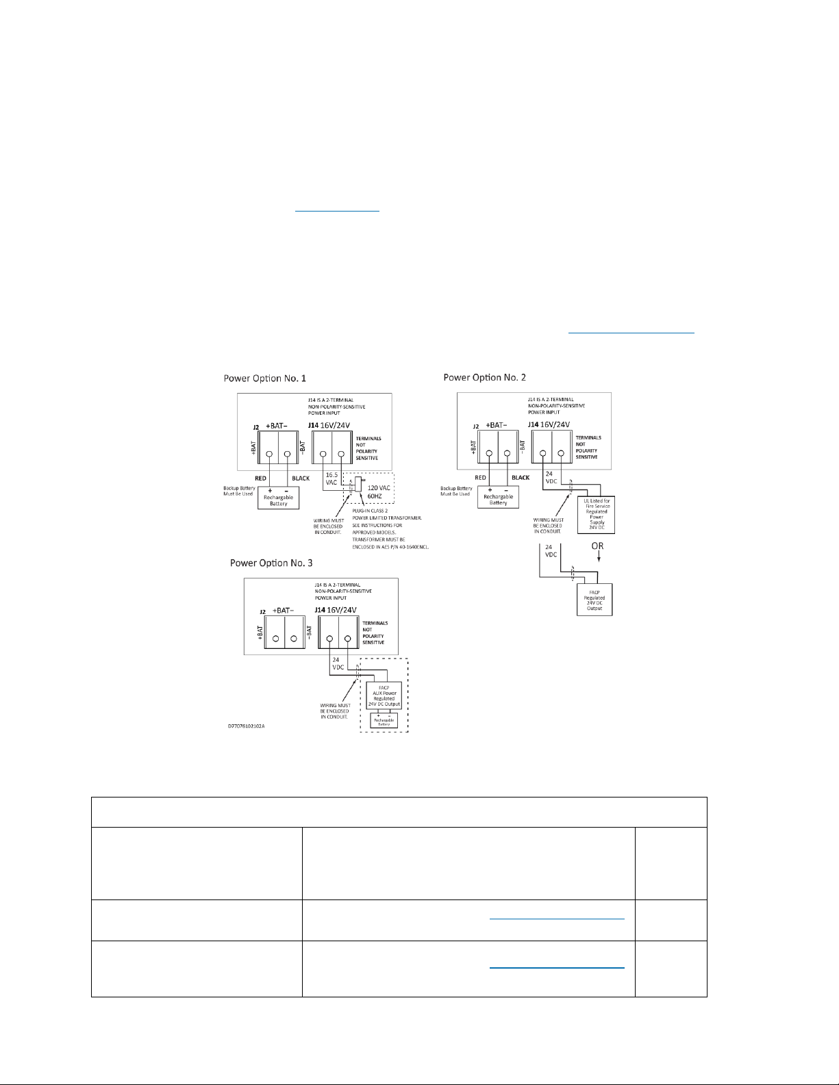
Power Options
The following diagram shows three options to supply the subscriber with power. The Flexible Power Option section
on page 40 provides instructions on how to configure the Subscriber software for the power option used.
Battery Size
Battery size requirements are listed in the following table:
Table 1. Battery Size Requirements
System Configuration
Description
Current (mA)
Battery
Size
(12 V)
7707
7711 (8 zone input card)
See Current Consumption under Technical Specifications
on page 8 and 7711 Installation and Operation Manual
10 Ah
7707
7712 (8 zone input card - 4 ea.
EOL and 4 ea. reverse polarity)
See Current Consumption under Technical Specifications
on page 8 and 7712 Installation and Operation Manual
10 Ah
Page 11
AES 7707 RF Subscriber 11
Part No. 40-7707 Rev. 3a 10/23/2017
Table 1. Battery Size Requirements
System Configuration
Description
Current (mA)
Battery
Size
(12 V)
7707
7794A (IntelliPro Fire Module)
7711 (8 zone input card)
See Current Consumption under Technical Specifications
on page 8, 7794A Installation and Operation Manual, and
7711 Installation and Operation Manual
12 Ah
7707
7794A (IntelliPro Fire Module)
7712 (8 zone input card - 4 ea.
EOL and 4 ea. reverse polarity)
See Current Consumption under Technical Specifications
on page 8, 7794A Installation and Operation Manual and
7712 Installation and Operation Manual
12 Ah
7707
7794A (IntelliPro Fire Module)
See Current Consumption under Technical Specifications
on page 8 and 7794A Installation and Operation Manual
12 Ah
4. Installation
Warning! Do NOT install the subscriber unit during a lightning storm.
4.1 7707 Installation
Table 2 lists tasks to perform when installing the AES 7707 Subscriber. Use the list to verify that installation tasks
have been identified and completed. Tasks do not have to be performed in the order listed unless specifically
identified.
Important! Verify AES mesh network connectivity for the subscriber before installing the subscriber enclosure.
Table 2. Installation Tasks
Page
Reference
Out of the Box
9
Subscriber Location/Network Connectivity
9
Antenna Selection and Location
9
Antenna Installation
17
Requirements
Environmental
9
Electrical Supply
10
Wiring Specifications
10
Battery Size
10
Enclosure Installation
Water Damage Prevention
13
Mounting the Enclosure
13
Removing the Mainboard
14
Removing the Zone Input Board
14
Page 12
AES 7707 RF Subscriber 12
Part No. 40-7707 Rev. 3a 10/23/2017
Table 2. Installation Tasks
Page
Reference
Removing the 7794A IntelliPro
14
Primary Power Wiring
Plug-In Transformer
15
Secondary Power Wiring
Battery Connection
16
Zone Input Wiring
7711 Zone Input (eight EOL resistor input)
19
7712 Zone Input (four EOL resistor and four reverse polarity inputs)
19
DACT Wiring
7794A IntelliPro
19
Configuration
Programming Options (UL Notice to Users)
23
Setup
Unit ID #
System Cipher Code (dealer code)
27
28
Timers
Check-In Time
AC Fail Report Delay
Communication Timeout
23
24
23
Zone Inputs
Set Zones (Bypass/Supervised/Fire)
Zone Restoral message
31
31
Advanced Configuration
Ground Fault Report
Secondary Alarm Delay
TTL
Subscriber IP Address
Subscriber Subnet Mask, Gateway, DNS
29
Saving Configuration Changes
26
System Operation
LCD Front Panel Display System Messages
Display Operation
33
System Status Display and 7707 Version Number
33
Unit ID and Serial Number
33
Link Layer and NetCon
33
Page 13
AES 7707 RF Subscriber 13
Part No. 40-7707 Rev. 3a 10/23/2017
Table 2. Installation Tasks
Page
Reference
Route Table
34
Zone Input Configuration Status
35
Network Connectivity Status
35
Battery and AC Power Status
35
Ground Fault and Battery Charger Status
35
Testing and Troubleshooting
Testing
43
Troubleshooting
44
4.2 Enclosure Installation
Water Damage Prevention
To prevent water damage, take the following precautions when mounting the unit:
Avoid mounting directly on exterior walls, especially masonry walls (condensation).
Avoid mounting directly on exterior walls below grade (condensation).
Important!
Protect unit from plumbing leaks.
Protect unit from splash caused by sprinkler system inspection ports.
Avoid mounting in areas with humidity-generating equipment (such as dryers or production machinery).
Important!
Route conduit to prevent moisture in the conduit from entering the subscriber.
Mounting the Enclosure
Check the Environmental Requirements on page 9 before starting. Mount in an area that is secure, as well as
accessible for service and testing. When mounting on an interior wall, use anchors and fasteners appropriate for the
wall material and total weight of subscriber and battery.
When mounting on a concrete wall, the unit must be placed to prevent moisture or water from entering the
enclosure. Use standoff material attached to the concrete surface to mount the enclosure. Two keyhole and two
circular mounting holes are available. Refer to the diagram below for location and sizes of mounting hole.
Page 14

AES 7707 RF Subscriber 14
Part No. 40-7707 Rev. 3a 10/23/2017
Figure 1. Enclosure Mounting – Hole Location and Sizes
Important! Use knockout plugs to close any unused conduit holes in the enclosure.
To remove electronic boards mounted in the enclosure, perform the following steps for boards installed.
Removing the 7794A IntelliPro
1. If the subscriber is supplied with a 7794A IntelliPro, remove the cabling. Remove the hex nuts holding the
board to the four standoffs.
2. Grasp the card and pull straight upward off the standoffs.
3. Remove the hex standoffs.
Removing the Zone Input Board
1. If the subscriber is supplied with a zone input board, remove the hex nuts holding the board to the
standoffs.
2. Grasp the board at each end by the standoff, and pull straight upward to unseat the card from the socket
connector on the Subscriber mainboard.
3. Remove the hex standoffs.
Removing the Mainboard
1. With all mounted boards removed from the top of the mainboard, remove the remaining hex nuts or
standoffs holding the mainboard to the enclosure.
2. Grasp the board on each side, and pull straight upward to lift the card off the mainboard support standoffs
attached to the enclosure.
Page 15

AES 7707 RF Subscriber 15
Part No. 40-7707 Rev. 3a 10/23/2017
5. Wiring
5.1 Primary Power Wiring
Plug-In Transformer
Warning! Turn off or disconnect all power before attempting to connect the 7707 Subscriber. Do NOT apply
power until all accessories are properly connected.
For U.S. installations, use only one of the Class 2 Direct Plug-in Transformers listed below:
Manufacturer
Model
Rating
ELK
ELK-TRG1640
16.5 V AC, 45 VA
MG Electronic Sales
MGT1640
16.5 V AC, 40 VA
AES Corp.
1640
16.5 V AC, 40 VA
For Canadian installations, use the CSA Listed Class 2 Direct Plug-in Transformer in the table below:
Manufacturer
Model
Rating
ATC-Frost Model
FPS4016
16.5 V AC, 40 VA
Important! All installations using plug-in transformers must use the AES Model 1640-ENCL Transformer
Enclosure for mechanical protection of the transformer. Wiring from the Transformer to the Subscriber must be
protected in conduit.
Refer to the wiring diagram for connection details, as well as for routing the battery, enclosure mounted antenna,
and the transceiver control cable. Leave a minimum of ¼ inch of spacing between non-power limited (battery
wiring) and power limited wiring as shown in the photo below and in the diagram below.
Figure 2. Wire Separation Non-Power Limited (left) Power Limited (right)
Earth Ground Connection
Earth ground and battery minus (-) are not separate connections in the 7707 Subscriber. Zone input terminals,
including the "G" terminals on zone input cards, are isolated from earth ground. Connect a suitable gauge wire as
specified in the applicable electrical code to the #8 ground stud as shown in the diagram below. Connect the wire to
Page 16

AES 7707 RF Subscriber 16
Part No. 40-7707 Rev. 3a 10/23/2017
a suitable earth ground, which includes building steel, buried metallic cold water pipe, driven grounding rod, and
other electrical code approved grounding systems. The electrical ground from the electrical panel is not suitable.
Use a ring terminal to connect the ground wire to the ground stud on the enclosure back box. Assemble the
connection as shown in the diagram below. Scrape paint from beneath the ring lug to ensure good metal contact.
Figure 3. Earth Ground Connection
5.2 Secondary Power Wiring
Battery Connection
Determine the correct Ah rating for the application using the Battery Size information on page 10.
Place the battery in the subscriber enclosure with the battery quick-connect terminals located to the right side of the
enclosure (refer to Figure 2, Wire Separation - Non-Power Limited and Power Limited Circuits on page 15).
The following steps and diagram below explain how to connect the backup battery.
1. Connect the BLACK wire from J2 to the negative (–) side of the battery.
2. Connect the RED wire from J2 to the positive (+) side of the battery.
Figure 4. Connecting the Backup Battery
Battery Replacement
The battery should be replaced every 3 years or when testing indicates replacement is required. Replace with the
same size and type installed. See Battery Replacement Instructions on page 44 for details.
Battery Only Restart
The 7707 Subscriber without AC power (for test or diagnostic purposes) will power up and self-test with only the
battery connected.
Battery Supervision
When AC power is present, the battery is tested at approximately 30-second intervals.
When the battery voltage is below 11.6 V DC for two consecutive test intervals (approximately 60 seconds total
time), a low-battery trouble message is transmitted.
When AC power is present and a low battery reaches a charge voltage above 12 V DC, a restoral message is
transmitted.
Page 17

AES 7707 RF Subscriber 17
Part No. 40-7707 Rev. 3a 10/23/2017
Replacing a low-charge battery with a fully charged battery may result in the subscriber not immediately detecting
the charged battery. Due to the test cycle time, up to 60 seconds can pass before the fully charged battery is
recognized.
Low Battery Voltage Cutoff
To prevent deep battery discharge damage, the 7707 subscriber disconnects the battery when voltage is less than
10 V DC.
Discharge/Recharge
The 7707 Subscriber float charges the battery using a 40 VA transformer. The battery voltage level conditions are:
Low Battery (Trouble message): Below 11.2 V DC
Subscriber Battery Disconnect: Below 10 V DC
Battery Reconnect (Restoral message): Above 12 V DC
6. External Antenna
6.1 Antenna Selection
A remotely mounted external antenna may be required for optimal performance on the mesh network, depending on
installation location requirements or conditions. Contact AES Corporation for additional antennas that may be used
with the 7707 Fire Subscriber unit.
6.2 Coaxial Cable and Connector Selection
Use 50-ohm impedance coaxial cable only. RG-8, 9913, LMR-400, and LMR-600 are acceptable coaxial
cables. RG-58 may be used for installations where cable is not more than 25 feet long.
Always use the shortest possible length of coaxial cable. Long lengths of coaxial cable result in greater
transmitted signal loss.
Always use the most direct routing in any coaxial cable installation. Unnecessary and tight bends add to
transmitted signal loss.
Use the proper coaxial connectors and crimp tool for the cable selected. Incorrect or poorly installed
connectors can cause transmitted signal power loss.
6.3 Antenna Location
When selecting an antenna location, keep the following in mind:
The supplied tamper-resistant and flexible 2.5-dB antenna mounts on top of the enclosure.
Remotely located antennas should be mounted as high as possible, either on top of or inside the building
structure. Rooftops and attic spaces are preferable.
The antenna needs to be high enough to overcome nearby obstructions to the RF signal path.
A remote antenna should be mounted in a location near the transceiver to minimize coaxial cable signal
loss. Do not use cable longer than needed to reach the antenna.
Avoid installing the antenna in close proximity to metal surfaces. Nearby metal may degrade radio
communications through signal reflections or antenna detuning.
Remember that pipes, conduit, wiring, ductwork, and other metal commonly installed within building walls
can affect antenna performance.
─ Take into account foil-backed insulation and wallpaper.
─ Metal objects can also be located in adjacent rooms or above ceilings.
─ Metallic framing and supports are commonly used in buildings. Do not mount the antenna directly
over, or close to, metal studding, beams, or other supports that can interfere with the RF signal.
6.4 Antenna Installation
Warning! Do NOT install Subscriber or antenna during a lightning storm.
The following installation guidelines must be followed when installing the antenna:
The remotely mounted antenna must be properly grounded to help reduce surge damage from lightning.
Grounding must be done in accordance with local building codes and in accordance with other
requirements from the Authority Having Jurisdiction (AHJ).
Mount the remote antenna vertically.
Do not coil or bunch coaxial cable.
Install the remote antenna in accordance with National Electric Code and local electric code.
Page 18

AES 7707 RF Subscriber 18
Part No. 40-7707 Rev. 3a 10/23/2017
6.5 Antenna and Surge Suppressor Grounding
A protective surge suppressor (AES Model 7230) must be installed in line with any type of remotely installed
antenna outside a building as shown in the diagram below. The surge suppressor and remote antenna must be earthgrounded. For U.S. installation, check National Electrical Code (NEC), state, or local electrical code requirements.
For Canadian installations, check Canadian Electrical Code, province, or local electrical code requirements.
Figure 5. Antenna and Surge Suppressor Grounding
Page 19

AES 7707 RF Subscriber 19
Part No. 40-7707 Rev. 3a 10/23/2017
7. System Configuration
7.1 Compatible Device List
Zone Input
7711 8 zone conventional EOL input
7712 8 zone (four EOL input and four reverse polarity input)
The 7707 will accept a single zone input card mounted in the Mainboard socket or stacked zone input cards using
the 7707 Mainboard Socket and Zone Input Card Socket. The table below shows input card and whether a Zone
Input Card Socket is present on the card.
7707 Mainboard Socket
*Zone Input Card Socket Present
7711
No
7712
No
Digital Dialer Interface
A single 7794A IntelliPro
Compatible Device Installation and Field Wiring Connections
7711 8 zone conventional EOL input: Refer to 7711 Install Manual AES, Part No. 40-7711
7712 8 zone input (four EOL input and four reverse polarity input): Refer to 7712 Install Manual
AES, Part No. 40-7712
7740 Remote Annunciator: Refer to page 44 of this document AES Model 7740 Annunciator
Installation Instructions.
IMPORTANT! : When no 7740 Remote Annunciator is installed, set DIPSW1 to “ON”. The ON side switch
position is shown in the photo below.
1.
Page 20

AES 7707 RF Subscriber 20
Part No. 40-7707 Rev. 3a 10/23/2017
7.2 System Configuration Diagram
7.3 System Communication Configuration
Sole Path (Single Reporting) utilizes either the AES mesh radio network or a TCP/IP broadband connection to
deliver messages from the subscriber to the central monitoring station.
Single Reporting with Backup utilizes either the AES mesh radio network, or a TCP/IP broadband connection, to
deliver messages from the subscriber to the central monitoring station. The Backup Reporting path works when the
Primary Reporting path is down.
Page 21

AES 7707 RF Subscriber 21
Part No. 40-7707 Rev. 3a 10/23/2017
Dual Reporting utilizes both the AES mesh radio network and the TCP/IP broadband connection. Messages from
the subscriber to the central monitoring station are launched on both paths together.
Page 22

AES 7707 RF Subscriber 22
Part No. 40-7707 Rev. 3a 10/23/2017
Figure 6. Field Wire Connections – 7707 Fire Subscriber Unit
Page 23

AES 7707 RF Subscriber 23
Part No. 40-7707 Rev. 3a 10/23/2017
7.4 Trouble Output
J4 – Trouble Relay Contacts – 24 V DC 1A Max. Resistive Load Unsupervised
Annunciator – AES Model 7740 Remote Annunciator – 21 V DC 25 mA Typ. (50 mA max.) Supervised.
Refer to the Compatible Device Installation and Field Wiring Connections section on page 19 for
instructions on installing and connecting field wiring on the Model 7740.
8. Programming
8.1 Programming Options (UL Notice to Users)
NOTICE TO USERS, INSTALLERS, AUTHORITIES HAVING JURISDICTION, AND
OTHER INVOLVED PARTIES
This product incorporates field-programmable software. In order for the product to comply with the requirements in the
Standard for Control Units and Accessories for Fire Alarm Systems, UL 864, certain programming features or options must be
limited to specific values or not used at all as indicated below.
Table 3. Limitations in Programming Features and Options
Topic
Feature or Option
Permitted
in UL
864/ULC
S559
Possible
Settings
Setting(s)
Permitted in UL
864/ULC S559
Comment
Radio
Secondary Alarm Delay
Y
1‒330 seconds
1‒10 seconds
Check-in Time
Y
0‒24 hours
0‒24 hours
Communication Timeout
Y
1‒300 seconds
1‒60 seconds
Repeating
Y
Y or N Y
Zone
Configuration
Zone Programming
Y
Supervised,
Fire,
or Bypass
Zone in use: Fire
Zone not in use:
Bypass
Supervised not to be
used in fire
applications.
Fire Zones
Y
Y or N
Y
Only if 7712
or 7711 is
used
Consecutive AT
Events
Y
Y or N
Y
Y for verbose zone
input alarm and
trouble message
reporting. Refer to
Pg. 31 for details.
Restoral Y
Y or N
Y
Power from 16.5 V AC and
Backup Battery
Y
16.5 V AC and
Backup Battery
Y
Plug in Class 2
transformer with
rechargeable backup
battery in Subscriber
Power
Options
24 V DC Regulated Power
Supply with Backup
Battery
Y
24 V DC and
Battery
Y
UL Listed for Fire Service
Regulated Power Supply
24 V DC or FACP 24 V DC
output. Rechargeable
backup battery in
Subscriber.
Page 24

AES 7707 RF Subscriber 24
Part No. 40-7707 Rev. 3a 10/23/2017
Table 3. Limitations in Programming Features and Options
Topic
Feature or Option
Permitted
in UL
864/ULC
S559
Possible
Settings
Setting(s)
Permitted in UL
864/ULC S559
Comment
24 V DC Regulated Power
Supply
Y
24 VDC only
Y
FACP AUX Power
24 V DC Regulated
output.
Rechargeable
backup battery in
FACP.
12 V DC Regulated Power
Supply
N
N/A
N/A
12 V DC Regulated
Power Supply not
allowed.
AC Fail/DC Fail Report
Delay
Y
0‒60, or R
(0‒60 minutes,
or random
time between
0‒60 min.)
0-60 (minutes)
R (random time
from 0‒60
minutes)
System
Locally Announce AC
Fault/DC Fault
Y
Y or N
Y
Suppress AC Fault/DC
Fault
N
Y or N
N
Suppress Charger Fault
N
Y or N
N
Suppress Battery Fault
N
Y or N
N
Suppress Ground Fault
Reporting
N
Y or N
N
Inet Check-In
Y
1 minute to
24 hours
6 hours
maximum
Important! UL and NFPA standards do not allow remote programming of an installed Model 7707 subscriber
unless an authorized person is present at the unit to enable temporary remote programming capability. Note: When
any zone is configured as Fire, remote programming can be performed only up to 10 minutes after the subscriber is
reset or powered up.
Page 25

AES 7707 RF Subscriber 25
Part No. 40-7707 Rev. 3a 10/23/2017
8.2 Programming Interface
Important! Eliminate false alarms by notifying the central station operator ahead of time before the Subscriber is
powered on. A false alarm/report and dispatch of services to the previous Subscriber location may occur if this is not
done.
The Model 7707 is programmed using a graphical interface through a smartphone, a laptop/tablet, or other web
browser capable device.
The Subscriber is connected to a LAN through the J10 Ethernet connector. The default network protocol is DHCP.
The IP address obtained is shown on the LCD display during Subscriber power-up. An example display is shown
below. The actual IP address will depend on the network a Subscriber is connected to.
Note: If DHCP is not available, the IP address is set to 169.254.100.1.
8.3 Logging In
Connecting to the 7707 configuration page requires a login. Enter the IP address of the subscriber in the web
browser. Then enter your username (in the Username box) and password at the login screen. The default User Name
and Password is admin (lower case):
The following screen appears after a successful login:
8.4 Configuration Interface
Navigation
Individual pages are listed in a tab bar:
To go to a page, select a tab by clicking on it. For example, the Tools page is accessed by pointing and clicking on
Tools. Each page displays a set of controls as shown below:
LAN: 10.0.3.111
Page 26

AES 7707 RF Subscriber 26
Part No. 40-7707 Rev. 3a 10/23/2017
Use the control to expand the control window. In this example, expanding Alarm History allows view of
messages similar to the example below:
Use the control to collapse the window.
The Log Out control ends the configuration session and returns to the Login screen.
Making Configuration Changes
Configuration settings are made and changed using either the dropdown or slider switch controls in the window.
The dropdown provides a list to select from:
The slider switch provides one of two values to select:
Saving Configuration Changes
Saving configuration changes requires the following steps:
1. When you are finished making changes, select and click the Save Changes button. The Saved new
settings! acknowledgement appears:
2.
2. You may finish and save your changes immediately, or you can make additional changes and then save all
changes at once afterward.
3. If done making changes, click the Update tab shown in the browser (highlighted in red in the figure
below):
4. The Status window is displayed after changes are saved as shown below:
8.5 View 7707 Subscriber Software Version
The 7707 software version is visible in the System tab window under System Firmware Upgrade.
1. Select the System tab, as shown highlighted in the following figure:
2. The version number is displayed in the System Firmware Update section.
8.6 View 7794A IntelliPro Software Version
Page 27

AES 7707 RF Subscriber 27
Part No. 40-7707 Rev. 3a 10/23/2017
The 7794A IntelliPro software version (when installed) is visible in the Status tab window under Hardware.
8.7 Change Login Password
1. Select the System tab as shown highlighted in red below:
2. Place the cursor in the Current Password text box, then type the current password.
3. In the New Password text box, type the new password. Type the new password again into the Confirm box
and click Change Password.
8.8 Subscriber Configuration
Subscriber ID
Subscriber ID and is set in the Configuration tab.
1. Select the Configuration tab shown highlighted in the following figure:
Note: Remote programming of ID and Cipher Code is not possible. The ID number entered must be unique from
any other ID number in the system.
2. Change the Sub ID by entering a 4 character hex (0-9 and A-F) identification number. Valid values are
0001 to FFFF.
Important! See Programming Options (UL Notice to Users) which starts on page 23 for software settings
permitted for the following parameters.
Event Reporting Route
1. From the main menu, click the Configuration tab.
2. In the Event Reporting panel click the Reporting Route dropdown and select the path for the subscriber
to communicate. Refer to Section 7.3 System Communication Configuration for diagrams showing each
Reporting Route selection.
Complete the configuration using the links shown below for the Event Reporting path selected for the Subscriber:
Radio Only: Radio Configuration (refer also to the AES Mesh Radio Network diagram on page 20)
Page 28

AES 7707 RF Subscriber 28
Part No. 40-7707 Rev. 3a 10/23/2017
Radio and Internet: Radio Configuration, Central Receiver Configuration and Subscriber IP Address under
Advanced Configuration (refer also to the Dual Reporting diagram on page 21).
Radio and Internet Backup: Radio Configuration, Central Receiver Configuration and Subscriber IP
Address under Advanced Configuration. Refer also to the Single Reporting with Backup diagram on
page 20.
Internet and Radio Backup: Radio Configuration, Central Receiver Configuration and Subscriber IP
Address under Advanced Configuration. Refer also to the Single Reporting with AES Radio Network
Backup diagram on page 20.
Internet Only: Central Receiver Configuration, and Subscriber IP Address under Advanced Configuration.
Refer also to the Internet diagram on page 20.
8.9 Radio Configuration
The Radio Configuration panel contains subscriber cipher code (dealer code), Check-In, Communication Timeout
and Repeating settings.
To set Radio Configuration:
1. Click the Configuration tab.
2. Scroll to the Radio Configuration panel.
Cipher: Enter the four-character hex (0‒9 and A‒F) cipher code (dealer code) assigned by the system
administrator. Valid values are 0000 to FFFF.
Note: The code must match the AES 7170 IP-Link cipher code for the network that the Subscriber is to
join. The Subscriber will not join the mesh network if the cipher code is incorrect.
Important! See Programming Options (UL Notice to Users) which starts on page 23 for software settings
permitted for the following parameters.
Check-In Time: Enter check-in hours and minutes. The default is 23:45 (23 hours 45 minutes).
Note: Using short check-in times generates more traffic on the network.
Communication Timeout: Communication Timeout is the time the Subscriber waits for an ACK as a
reply to a transmitted packet or when the Subscriber is at NetCon 7 and is waiting to join the mesh network.
The range is 1‒300 seconds. The default and maximum time allowed for this option is 60 seconds.
Repeating: Set Repeating to Enabled/Disabled by clicking on the Repeating switch.
Important! UL-864 compliant Fire Alarm installations require Repeating to be set to Yes. See the
Programming Options (UL Notice to Users) which starts on page 23 for software settings permitted for the
following parameter.
8.10 Central Receiver Configuration
The Central Receiver panel contains Internet connection settings to the MultiNet receiver.
Note: Central Receiver Configuration must be set when using IP Reporting.
Page 29

AES 7707 RF Subscriber 29
Part No. 40-7707 Rev. 3a 10/23/2017
To set Central Receiver Configuration:
1. Click the Configuration tab.
2. Scroll to the Central Receiver panel.
IP Group ID: Enter the assigned ID as found in Business Unit Settings.
Primary Receiver IP: Enter the Primary Receiver IP address.
Primary Receiver Port: Enter the Primary Receiver Port number.
Secondary Receiver IP: Enter the Secondary Receiver IP address.
Secondary Receiver Port: Enter the Secondary Receiver Port number.
Important! See Programming Options (UL Notice to Users) which starts on page 23 for software
settings permitted for the following parameter. (Inet Check-In)
Inet Check-In: Enter the check-in time interval for the subscriber.
MCT Timeout: Enter the MCT (Multiple Communications Technology) Timeout. The MCT
Timeout sets the amount of time the subscriber tries to send messages though one communication
technology before giving up and switching to the other technology.
8.11 Advanced Configuration
From the Advanced Configurations menu, you can configure the ground fault reporting, Secondary Alarm Delay,
TTL (Time to Live) and the subscriber IP address. To configure these settings:
1. Select the Configuration tab.
2. Scroll to the Advanced Configuration panel.
Suppress Ground Fault Report
Important! UL-864 compliant Fire Alarm installations require Suppress Ground Fault Reporting
to be set to No. See the Programming Options (UL Notice to Users) which starts on page 23 for
software settings permitted for the following parameter.
Set Suppress Ground Fault Report to Yes/No by clicking the Suppress Ground Fault Report
switch.
Secondary Alarm Delay
Enter the number of seconds allowed between data transmissions from the Subscriber. The range is 1‒
330 seconds. The default and maximum time allowed for this setting is 10 seconds.
Note: The first message is sent immediately without delay. Messages that follow are delayed.
TTL (Time-To-Live) Configuration
Time-to-Live settings are for managing the performance of the AES mesh network. TTL is the length
of time a packet message transmission for a specific setting is retried by a Subscriber in the AES mesh
network. The Subscriber will stop attempting to transmit the packet when the TTL limit has expired.
To set Time-to-Live:
1. Scroll to the Configuration tab.
2. Select the Advanced Configuration panel and configure the setting:
Page 30

AES 7707 RF Subscriber 30
Part No. 40-7707 Rev. 3a 10/23/2017
Message Type
TTL
CHECK-IN
10 minutes
STATUS
10 minutes
ALARM
3:00 hours
TROUBLE
3:00 hours
RESTORAL
3:00 hours
INTELLITAP
10 minutes
SPECIAL
10 minutes
Subscriber IP Address Information
To set Subscriber IP Address
1. Scroll to the Configuration tab.
2. Select the Advanced Configuration panel and configure the settings:
Subscriber IP Address type: Select STATIC or DHCP
If STATIC address is selected, enter the following information:
IP Address – The IP address of the subscriber
Subnet Mask
Gateway
DNS Server 1 (Optional)
DNS Server 2 (Optional)
8.12 Zone Input Configuration
Zone input cards and Model 7794A IntelliPro are configured under the Accessories tab in the browser.
You can verify that a zone input card for 7794A IntelliPro is installed by selecting the Status tab and checking the
Hardware panel. In this example, a single 8 zone input card is installed in the first zone bank (Zone Bank 0) and
nothing installed in the second zone bank:
To configure zone input cards for the 7794A IntelliPro:
1. Select the Accessories tab shown in red below:
A Bank Zone panel will appear when the Model 7707 has a zone input card installed.
If a 7794A IntelliPro is installed, the IntelliPro panel will appear as shown below:
Page 31

AES 7707 RF Subscriber 31
Part No. 40-7707 Rev. 3a 10/23/2017
A Model 7711 8 Zone Input Card menu appears as shown below:
The 7711 Zone Input Card for use with Fire Alarm Control Panels (FACP) can be programmed for:
Fire – The EOL 2.2k ohm resistor circuit reports trouble for open circuit and alarm for short circuit.
Bypassed – Zone input is ignored.
Zone Input Condition
Zone Programming
Fire
Bypass
2.2k ohm EOL resistor circuit
Normal
Input Ignored
Open circuit
Trouble
Input Ignored
Short/closed circuit
Alarm
Input Ignored
2. Set the Fire Zones switch to Yes to set the input type as fire.
3. Set Consecutive AT Events (Consecutive Alarm/Trouble Events) to Yes for verbose reporting of alarm
and trouble messages. When Consecutive AT Events is enabled and an event occurs, an alarm or trouble
message will be sent regardless of the number events. One example is the sequence of messages “alarm –
trouble – alarm – trouble …” Set to No for non-verbose reporting. When disabled, an alarm and a trouble
will be sent once only, even when a zone might be continually changing state multiple times.
4. Select the zone behavior (either Bypassed or Fire) for each zone using the dropdown box.
Important! Wiring of any FACP relay output to any 7707 zone input must use an EOL resistor supervised
zone programmed as Fire (F). Zone inputs Z1 through Z8 on the Model 7711 meet this requirement.
Note: Set all unused zones to Bypassed. Do NOT install EOL resistors on Bypassed zones.
8.13 Restoral
Restoral messages are sent for the zone when the Restoral switch is set to Yes. When finished with Configuration,
save the configuration by clicking Save Changes.
7794A IntelliPro Configuration
Note: You will need a copy of the 7794A IntelliPro Fire Installation Manual (AES P/N 40-7794A) for IntelliPro
configuration settings.
Page 32

AES 7707 RF Subscriber 32
Part No. 40-7707 Rev. 3a 10/23/2017
The IntelliPro panel will appear if a Model 7794A IntelliPro is installed in the Subscriber. The configuration menu
will appear as shown below:
Refer to the 7794A IntelliPro Fire Installation Manual (AES P/N 40-7794A) for instructions on configuring the
settings.
When done with changes, click the Save Changes button.
8.14 Status LED Indicators
The five LED indicators on the main circuit board of the Model 7707 show system status. The LEDs are located
near the top edge of circuit board below the J7/APM connector and near the RESET button as shown below:
Table 4. System Status LED Indicators
LED
Color
Function
ALM
Red
Status/troubleshooting indicator, “blink” (see ALM LED Blink Patterns table below)
WA
Yellow
Steady On = Waiting for acknowledgment of last transmission
Steady Blinking = Not on Network
Off = Normal
TX
Yellow
On = Radio transmit
RX
Green
On = Radio transceiver receiving RF signal
NOTE: If RX is on steady for longer than 20 seconds, an interfering RF signal exists. Any RF
signals that are on the same frequency as the subscriber and which are strong enough to break
the squelch will also cause the RX light to remain on.
Trbl
Red
Blinking Continuously = Trouble Condition. Refer to Table 6 for trouble details.
Page 33

AES 7707 RF Subscriber 33
Part No. 40-7707 Rev. 3a 10/23/2017
ALM LED Blink Pattern Chart
The chart below shows blink patterns utilized by the ALM LED, as well as possible meanings:
Table 5. ALM LED Blink Patterns
Blink Type
Pattern
Possible Meaning(s)
Steady blink
•••
Normal operation
Short-short blink
•••
Low battery
Short-long
•••
Zone input in alarm or
trouble/off normal
Short-short-long
•••
Low battery and zone in
alarm/trouble
Short-short-pause-short
•••
AC Fault
Short-short-pause-short-short
•••
AC Fault and low battery
Steady/no blink
Self-test failure (excluding low
battery and AC)
Symbols as follows: "" = short blink, " " = long blink
The period between patterns is about 1 second (the chart shows each pattern repeating three times).
8.15 LCD Front Panel Display System Messages
Display Operation
The 7707 subscriber uses a combination LCD display and a MENU pushbutton switch to navigate through the
system message screens.
Note: Pressing and releasing the MENU button allows you to advance in a loop through the display screens until
returning the System Status display screen.
System Status Display and 7707 Version Number
When the Model 7707 is operating normally, the Normal System Status screen is shown in the LCD. The model
number, software version number, and status message are displayed as shown below:
Press the MENU button on the front of the enclosure once to advance to the Unit ID and Serial Number status
display.
Note: Pressing and releasing the MENU button allows you to advance in a loop through the display screens until
7707 VER:X.XXXX
STATUS: NORMAL
Page 34

AES 7707 RF Subscriber 34
Part No. 40-7707 Rev. 3a 10/23/2017
returning the System Status display screen.
Unit ID and Serial Number
Note: The Subscriber ID can be viewed but cannot be set through the System Messages display. Use the
configuration web page to change the Subscriber ID.
Link Layer and NetCon
Press the MENU button once to advance to the Local Status Check screen, where Subscriber Link Layer and
NetCon values are displayed.
Press the MENU button once to advance to the Routing Table Display screen:
A total of four display screens are available to show the routing table. Up to eight peers, subscribers, or IP
Links may be listed in the table. Each screen displays two subscribers. The total number of display screens
will vary depending on the total number of peers listed (a number from 1 to 8). Press the MENU button
once to advance to the next routing table screen.
Routing Table ID#: A routing table lists up to eight other subscribers ID#'s or IP Links in a table. The
purpose of the list is to select a peer for passing off data packets. The table is sorted with the best quality
Subscriber placed at preference location 1. Quality is a measure of the neighbor Subscriber's ability to pass
data packets.
L: Link Layer as reported by last transmission from the peer ID# shown.
N: NetCon (NETwork CONnectivity) – An internal rating used in the automatic positioning of this
unit in the network. A NetCon value of 5 is required for a subscriber that is compliant with UL-864,
10th Edition.
Q: Signal Quality – The first digit is either an 8 or a 0 (zero). The second digit is a measure of how
old the data is (a 3 is assigned to the newest data; a 1 is assigned to older data). Routing preference is
given to strong, recently heard subscribers (03) versus weaker subscribers heard a long time ago (81).
Route Table
ID: B10B
Serial No: B07
LINK LAYER: 1
NETCON: 5
1.AA1A L:00 N:0 Q:03
2.A21A L:01 N:5 Q:03
Page 35

AES 7707 RF Subscriber 35
Part No. 40-7707 Rev. 3a 10/23/2017
Press the MENU button to view the next status message. Additional routing table screens may appear
depending on the number of routes available.
Zone Input Configuration
The status of each zone input for a 7711 zone input card is shown. Values are F for Fire, S for Supervised,
or B for Bypass.
Press the MENU button to view the next status message.
Network Connectivity Status
The IP address and IP connection (DHCP or Static Address) are shown:
When no IP network is available, the No LAN IP message appears as shown below:
Press the MENU button to view the next status message.
Battery and AC Power Status
Press the MENU button to view the next status message.
Ground Fault and Battery Charger Status
Press the MENU button to view the next message.
7794A IntelliPro Software Version
If a 7794A IntelliPro is installed in the Subscriber, the software version will appear as shown below, where
X.XXX is the version number:
When no 7794A is present, the display will show None as shown below:
ZONE:1-F 2-F 3-F 4-F
ZONE:5-F 6-F 7-F 8-F
LAN: 10.0.3.111
LAN: No LAN IP
BATTERY OK
AC POWER OK
GROUND OK
CHARGER OK
Panel Interface:
7794A Ver X.XXX
Panel Interface:
None
Page 36

AES 7707 RF Subscriber 36
Part No. 40-7707 Rev. 3a 10/23/2017
Press the MENU button to return to the home screen, which is the System Status Display.
8.16 Off-Normal Operation
Faults and alarms that cause off-normal operation are shown with fault messages in the LCD display. See table
below for more information.
Table 6. Faults and Alarms with Off-Normal Operation
Off-Normal Condition
Fault Message
Problem
AC POWER FAIL
AC power to Subscriber disconnected or below minimum voltage
DC POWER FAIL
DC power to Subscriber disconnected or below minimum voltage
CHARGER
Battery charger failure
NETCON
Subscriber NetCon value below minimum required
GROUND FAIL
Resistance to earth ground below limit on zone input
AP IFACE FAIL
7794A IntelliPro card failure
RF COMM FAIL
Failure to communicate with another unit on mesh network
ANNUNC FAIL
7740 Remote Annunciator failure
BATTERY FAIL
Backup battery voltage below minimum
Alarm/Trouble Messages
ZONE 2 ALARM
Example of Alarm condition; Zone 2 input
ZONE 7 TRBL
Example of Trouble condition; Zone 7 input
Fault Display
Faults are shown on the LCD display on the enclosure. The following behavior occurs depending on whether single
or multiple fault conditions exist.
Single fault – A single fault condition is shown on the display, and the Subscriber buzzer sounds as shown
below:
When the single fault condition clears, the cleared fault message no longer displays and the buzzer stops
sounding.
Buzzer Silence – Press the MENU button and hold down for at least 5 seconds. The status display will show
the following, and the buzzer will be silenced.
Multiple faults – Multiple faults are shown in the LCD display one fault at a time for approximately 2
seconds each. Faults appear in sequential order, and the Subscriber buzzer sounds as shown below:
Buzzer Silence – Press the MENU button and hold down for at least 5 seconds.
8.17 Disable On Board Buzzer
The front panel buzzer can be disabled through the configuration interface if a remote annunciator is used. To
disable the onboard buzzer in the Subscriber:
1. Select the System tab.
2. Under the Buzzer panel, set the On Board Buzzer switch from Enabled to Disabled to silence the buzzer.
7707 VER:X.XXXX
Status: AC FAIL
7707 VER:X.XXXX
Status: SILENCED
Page 37

AES 7707 RF Subscriber 37
Part No. 40-7707 Rev. 3a 10/23/2017
3. Click the Save Change button.
4. Click Update.
8.18 Subscriber Status Check
General
Information about the Model 7707 Subscriber is shown in the Status panel. The Subscriber model, firmware
version, and status can be viewed by selecting the Status tab as shown in red below:
The Subscriber model number and software version are displayed:
The Status page shows any faults, as well as the unit (subscriber) RF ID, Link Layer, and NetCon values:
Faults are displayed below the status panel.
Routing Table
The Subscriber routing table is displayed in the Routes panel as shown below. Up to eight routes may be included:
Hardware
Information about the Subscriber type, serial number, zone input configuration, alarm panel type, and IP addresses
are shown in the Hardware panel.
Model type – The Model 7707, a Fire Subscriber, displays as type FIRE.
Serial Number – A unique serial number is assigned to each Model 7707 Subscriber at the factory.
Zone Bank details – A zone bank can have a zone input card connected, or it may be empty depending on
how the Model 7707 is configured. When no zone input card is present, the zone bank displays None.
Panel Interface – 7794A IntelliPro
Wired MAC/Wired IPv4 – The Media Access Control (MAC) address (which is the physical address) is a
unique network identifier assigned to the Model 7707 Subscriber.
WiFi IPv4 – The address of a USB WiFi adapter (optional, supplied by others) used for wireless
connection to the Subscriber during configuration is shown.
8.19 Tools
The Tools tab provides access to the following:
Text Messages
Alarm History
RF Traffic
IP Traffic
RF Antenna Test
Page 38

AES 7707 RF Subscriber 38
Part No. 40-7707 Rev. 3a 10/23/2017
Ping
System Activity Log
To access these features, select the Tools tab as shown in red below:
Text Message
A text message can be sent from the 7707 Subscriber to the central monitoring station. Messages from the central
station can also be received.
In the Text Messages panel, use the message line at the bottom of the panel to enter the message. Messages have a
200-character limit. Click the Send button to transmit the message.
Alarm History
Messages sent from the Model 7707 Subscriber, or the alarm panel connected to the Model 7707 Subscriber, are
displayed in the Alarm History user interface panel.
RF Traffic
Receive and transmit traffic to/from the Subscriber can be viewed using the RF Traffic panel. Traffic from other
subscribers can also be viewed.
IP Traffic
Messages that are sent to and from the Subscriber, and which are used for debugging purposes, are displayed in the
IP Traffic panel.
RF Antenna Test
The RF Antenna Test turns the transceiver transmitter on for approximately 5 seconds and allows use of RF test
equipment, such as a SWR meter or power meter. This function allows you to check transceiver RF power output,
coaxial cable connections, antenna tuning, and other parameters.
Ping
The ping utility checks network connectivity of the Subscriber. Enter a network address on the form line and click
Submit to verify the connection.
System Activity Log
The System Activity Log shows 7707 subscriber information used diagnostic purposes.
8.20 IP Configuration
The IP address of the Subscriber is set in the Configuration tab under the Advanced Conf. Fixed (static) or
automatically assigned (DHCP) addresses may be used. DHCP addressing is the default setting.
Select the IP Configuration tab.
IP Address – DHCP
The Subscriber is set to Dynamic Host Configuration Protocol (DHCP) by default. An address is automatically
obtained when the Subscriber is connected to a network, or if already connected, when the Subscriber is powered on.
IP Address – Static
When Static is selected, the form expands to show:
Page 39

AES 7707 RF Subscriber 39
Part No. 40-7707 Rev. 3a 10/23/2017
IP Address
Subnet Mask
Gateway
DNS Server 1
DNS Server 2 (Optional)
Obtain information for these settings from the network administrator or other individual who manages network
services.
9. System Settings
The System tab provides access to system setting features.
9.1 Product License
Subscriber product license information is displayed in this panel.
9.2 Change Password
Change Password allows the logged in user to set another password for the login account. If the user is logged in
with a default account password, a warning about changing the password appears in red letters.
The Login User line displays the current user logged into the Subscriber.
To change the password:
1. Enter the existing password into the “Current Password” field.
2. Enter a new password into the “New Password” field.
3. Re-enter the new password again into the “Confirm” field.
9.3 Add User
Add User allows you to add additional users to the system.
To add a user:
1. Enter the user name into the “Username” field.
2. Enter the password into the “Password” field.
3. Re-enter the password again into the “Confirm” field.
4. When through, click the Add User button.
9.4 Buzzer – Onboard Subscriber
The buzzer control enables or silences the onboard Subscriber buzzer. The onboard buzzer can be silenced when a
remote annunciator is used. The default setting is Enabled.
1. To disable, click the Enable control so that it changes to Disabled.
2. When through, click the Save Change button.
9.5 Uploading/Downloading Settings
Download Current Settings
Setting information can be downloaded from the Subscriber. Click the Download button.
Upload Preconfigured Settings
To upload Subscriber settings to the Model 7707, click the Choose File button, select the file, and click the Upload
button.
Reset to Default Configuration
Subscriber and IntelliPro settings can be set to factory defaults.
1. Set the Subscriber Config and/or IntelliPro Config switch to Yes.
2. Click the Reset Configuration button.
Note: Reset with Subscriber Config does not change the existing Subscriber ID and cipher code programmed into
the unit.
Page 40

AES 7707 RF Subscriber 40
Part No. 40-7707 Rev. 3a 10/23/2017
9.6 System Firmware Update
Upgrading
To upgrade the Subscriber software, clicking the Choose File button, select the upgrade file, and click the Update
button.
Download Support Files
To download system information files, select the file type from the Select file type dropdown box, then click the
Download button.
Restart System
Clicking the Restart button causes the Subscriber to halt communication and any system software that may be
running. The system software restarts and the Subscriber resumes communication. Note: Remote programming is
enabled for 10 minutes after a Restart/Reset.
10. Flexible Power Option
Subscriber power can be provided by several different types of power sources. This control configures the type of
power source and the features associated with the power source. From the Configuration tab, select the Flexible
Power Option panel.
For power source details, see Power Options on page 10. See also Programming Options (UL Notice to Users)
which starts on page 23.
Power From: 16.5 V AC Adapter and Battery
Refer to the diagram shown in the Power Options section on page 10 for supply and connection
requirements.
Important! When using this selection, 16.5 V AC is the primary power source and the battery is
the secondary power source.
AC Report Delay: AC Report Delay is active when Suppress AC Fault is set to NO. The report
delay is the time that must pass before the Model 7707 Subscriber will send an AC failure or AC
restoral message. This feature helps prevent mesh network congestion in an area where many
Subscribers have an AC power outage at the same time. Messages can be set to transmit in a staggered
fashion using the Random time setting.
Note: Primary (16.5 V AC) power failure fault reporting must be enabled for compliance with UL 864
standard in fire installations.
The combined AC Fail detection time delay of 100 minutes plus the random AC Report Delay between 0‒
60 minutes results in time that does not exceed 160 minutes. This is within the UL-864 requirement of
reporting AC power failure within 180 minutes (3 hours) of loss.
Primary (16.5 V AC) power must be lost for 100 minutes in order to be reported as a failure. Primary (16.5
V AC) power must be restored for at least 100 minutes to be reported as a restore. Once either is detected,
a message is created by the Subscriber to send to the central station. An AC Report Delay is selected based
on both this parameter and the setting of Suppress AC Fault Reporting.
Page 41

AES 7707 RF Subscriber 41
Part No. 40-7707 Rev. 3a 10/23/2017
Available settings:
─ Random Delay ─ A random time ranging from 0‒60 minutes after 100 minutes of primary (16.5 V
AC) power loss. Enter R into the box to select this option.
─ Fixed delay ─ A specific time ranging from 1‒60 minutes after 100 minutes of primary (16.5 V
AC) power loss.
─ No Delay ─ Immediate transmission after 100 minutes of primary (16.5 V AC) power loss.
Locally Announce AC Fault
Important! UL-864 compliant fire alarm installations require that Locally Announce AC Fault be set to
Yes. See the Programming Options (UL Notice to Users) on page 23 for software settings permitted for the
following parameter.
Set Locally Announce AC Fault to Yes/No by clicking the Locally Announce AC Fault switch.
Suppress AC Fault Reporting
Important! UL-864 compliant fire alarm installations require that Suppress AC Fault Reporting be set to
No. See the Programming Options (UL Notice to Users) on page 23 for software settings permitted for the
following parameter.
Set AC Fault Reporting to Yes/No by clicking the AC Fault Reporting switch.
Suppress Battery Fault Reporting
Important! UL-864 compliant fire alarm installations require that Suppress Battery Fault Reporting be
set to No. See the Programming Options (UL Notice to Users) which starts on page 23 for software settings
permitted for the following parameter.
Suppress Charger Fault Report
Important! UL-864 compliant fire alarm installations require that Suppress Charger Fault Reporting
be set to No. See the Programming Options (UL Notice to Users) which starts on page 23 for software
settings permitted for the following parameter.
Set Suppress Charger Fault Report to Yes/No by clicking the Suppress Charger Fault Report
switch.
Power From: 24 V DC and Battery
Refer to the diagram shown in the Power Options section on page 10 for supply and connection
requirements.
Important! When using this selection, 24 V DC is the primary power source and the
battery is the secondary power source.
Page 42

AES 7707 RF Subscriber 42
Part No. 40-7707 Rev. 3a 10/23/2017
DC Report Delay: DC Report Delay is active when Suppress DC Power Fault is set to No. The
report delay is the time that must pass before the Model 7707 Subscriber will send a primary power
failure or primary restoral message. This feature helps prevent mesh network congestion in an area
where many subscribers have a power outage at the same time. Messages can be set to transmit in a
staggered fashion using the Random time setting.
Note: Primary power (24 V DC) failure fault reporting must be enabled for compliance with UL-864
standard in fire installations.
The combined DC fail detection time delay of 100 minutes plus the random DC Report Delay between 0‒
60 minutes results in time that does not exceed 160 minutes. This is within the UL-864 requirement of
reporting DC power failure within 180 minutes (3 hours) of loss.
Primary (24 V DC) power must be lost for 100 minutes in order to be reported as a failure. Primary (24 V
DC) power must be restored for at least 100 minutes to be reported as a restore. Once either is detected, a
message is created by the Subscriber to send to the central station. A DC Report Delay is selected based on
this parameter and the setting of Suppress DC Fault reporting. Available settings:
─ Random Delay ─ A random time ranging from 0‒60 minutes after 100 minutes of primary (24 V
DC) power loss. Enter R in the box to select this option.
─ Fixed Delay ─ A specific time ranging from 1‒60 minutes after 100 minutes of primary (24 V DC)
power loss.
─ No Delay ─ Immediate transmission after 100 minutes of primary (24 V DC) power loss.
Locally Announce DC Fault
Important! UL-864 compliant Fire Alarm installations require Locally Announce DC Fault to be set to
Yes. See the Programming Options (UL Notice to Users) on page 23 for software settings permitted for the
following parameter.
Set Locally Announce DC Fault to Yes/No by clicking the Locally Announce DC Fault switch.
Suppress DC Power Fault
Important! UL-864 compliant Fire Alarm installations require Suppress DC Power Fault to be set to
No. See the Programming Options (UL Notice to Users) which starts on page 23 for software settings
permitted for the following parameter.
Set Suppress DC Power Fault to Yes/No by clicking the Suppress DC Power Fault switch.
Suppress Battery Fault Reporting
Important! UL-864 compliant Fire Alarm installations require Suppress Battery Fault Reporting to be
set to No. See the Programming Options (UL Notice to Users) which on page 23 for software settings
permitted for the following parameter.
Suppress Charger Fault Reporting
Important! UL-864 compliant Fire Alarm installations require Suppress Charger Fault Reporting to be
set to No. See the Programming Options (UL Notice to Users) which starts on page 23 for software settings
permitted for the following parameter.
Set Suppress DC Power Fault to Yes/No by clicking the Suppress Charger Fault Reporting switch.
Power From: 24 V DC Only
Refer to the diagram shown in the Power Options section on page 10 for supply and connection
requirements.
Note: Selecting the 24 V DC only option causes Suppress Battery Fault and Suppress Charger Fault to
Page 43

AES 7707 RF Subscriber 43
Part No. 40-7707 Rev. 3a 10/23/2017
be grayed out in the interface. The two options cannot be changed.
Suppress DC Power Fault
Important! UL-864 compliant Fire Alarm installations require Suppress DC Power Fault to be set to
No. See the Programming Options (UL Notice to Users) which starts on page 23 for software settings
permitted for the following parameter.
Set Suppress DC Power Fault to Yes/No by clicking the Suppress DC Power Fault switch.
Power From: 12 V DC Only
Important! 12 V DC Only setting is not allowed for UL-864 compliant fire alarm installations.
Note: Selecting the 12 V DC only option causes Suppress Battery Fault and Suppress
Charger Fault to be grayed out in the interface. The two options cannot be changed.
11. Reporting
11.1 AES Mesh Network
The 7707 Subscriber can eliminate the need for POTS telephone lines by communicating with the 7705i MultiNet
using the AES mesh radio network.
11.2 Compatible Receiver
The 7707 Subscriber is compatible with the AES Corp. Model 7705i MultiNet Receiver.
12. Testing
Some of the tests to be performed at the installation site require a response from a person at the central station:
Trigger alarm conditions: Confirm that the proper message is received at the Central Station.
Cause fault conditions: Confirm that the proper message is received at the Central Station.
If any 7794A IntelliPro is installed, activate the alarm panel connected to the 7794A and confirm
that the 7794A handles alarm panel messages.
Page 44

AES 7707 RF Subscriber 44
Part No. 40-7707 Rev. 3a 10/23/2017
13. Maintenance
Once installed and normal operation is confirmed, minimal maintenance is required. Monitoring the automatic
check-in test messages will confirm proper RF operation. Batteries should be periodically tested to be certain they
have sufficient capacity to operate the system.
14. Troubleshooting
The most common causes of an RF failure or trouble are due to:
Antenna type
Antenna location
Coaxial cable
Coaxial connectors
Transceiver malfunction
Antennas close to metal or conductive material that block or reflect the transmitted signal are the most common
problems.
Try different locations for the antenna or use a remotely mounted long-range RF antenna. Try replacing the
transmission components, including the coaxial cable, coaxial connectors, or antenna.
Note: No user serviceable components are located on the circuit boards. Defective circuit board units must be
returned to AES. For information on returning units, see the AES Service Procedure under Warranty on page 46.
15. Repair Information
Other than the backup battery, no user serviceable parts are located in the 7707 Subscriber.
16. Battery Replacement Instructions
1. Remove the positive battery lead (red) from the battery.
2. Remove the negative battery lead (black) from the battery.
3. Verify that the POWER LED indicator is NOT illuminated.
4. Remove the battery from the enclosure.
5. Discard the battery in accordance with local disposal codes.
6. Install the new battery into the enclosure.
Note: Observe ¼ in. minimum separation between non-power limited wiring and power limited
wiring.
7. Connect the negative battery lead (black) to the battery.
8. Connect the positive battery lead (red) to the battery.
9. Perform Subscriber power-up and self-test procedure.
17. AES Model 7740 Annunciator Installation Instructions
17.1 Out of the Box
One Rocker Switch Annunciator with standard ring back
One Faceplate (red)
One Gang Back Box (red)
Assembly hardware is included. Wall mounting hardware is not included.
17.2 Installation Instructions
Utilize a standard single-gang mounting box. One gang space is required for each module to be installed. A
standard cover plate is required to cover the assembly.
1. Label the legend sheet for the AES Model 7740.
2. Mount the box securely into the wall.
Page 45

AES 7707 RF Subscriber 45
Part No. 40-7707 Rev. 3a 10/23/2017
3. Connect conduit and/or pull wiring as required.
4. Remove the faceplate from the frame.
Note: Notice the routing of the Silence switch cable if applicable. In most cases, this cable need not be
disconnected. Use the slack cable to allow the faceplate to be moved out of the way.
5. Terminate wires and connect the AES Model 7740 Local Annunciator, as shown in the following diagram.
The 7740 is powered and supervised by the AES Model 7707 Subscriber.
Figure 7. 7740 Wiring Diagram
6. Attach the frame to the box using frame screws.
7. Reinsert the faceplate into the frame.
8. Single-gang installation only.
9. Review and confirm field wiring and setup.
10. Damage and/or malfunction can result from improper wiring and/or setup.
11. Place the cover over the faceplate and secure with cover screws.
12. Power up the system and test for proper operation of all zones and functions.
Figure 8. 7740 Wire Inputs
18. AES Corp. Contact Information
AES Corporation
285 Newbury Street
Peabody, Massachusetts 01960 USA
Website: http://www.aes-corp.com
AES corporate Phone: (800) 237-6387 (800) AES-NETS
USA (978) 535-7310
Fax: USA (978) 535-7313
Email: Check Website for latest email addresses
Page 46

AES 7707 RF Subscriber 46
Part No. 40-7707 Rev. 3a 10/23/2017
19. Warranty
LIMITED PRODUCT WARRANTY
AES warrants to the original purchaser that the AES Subscriber Unit will be free from defects in
material and workmanship under normal use and service for three (3) years from the date of
original purchaser's purchase. Except as required by law, this Limited Warranty is made only to the
original purchaser and may not be transferred to any third party.
This Limited Product Warranty is made in lieu of any other warranties, expressed or implied, it
being understood that all other warranties, expressed or implied, inclusive of merchantability or
fitness for a particular purpose, are hereby expressly excluded.
AES assumes no liability for any personal injury, property damage, consequential damages, or any
other loss or damage due, among other things, to this product's failure to operate or provide
adequate warning. AES's sole responsibility is to repair or replace, at AES's sole option, the AES
product that is judged defected by AES during the limited warranty period under the terms of its
Limited Warranty.
TECHNOLOGY LICENSE
Certain AES Products include software, protocols and other proprietary and confidential technology and
trade secrets of AES which are incorporated in or provided with AES Products solely for use in conjunction
with and in order to operate AES Products (“Licensed Technology”). AES grants the original purchaser a
non-exclusive license to use such Licensed Technology solely in connection with the use and operation of
AES Products and for no other purpose or use whatsoever. No title or ownership in or to any such Licensed
Technology is conveyed by the sale or delivery of any AES Products; all such rights are retained by AES.
AES SERVICE PROCEDURE: Contact AES by Phone (978) 535-7310, Fax (978) 535-7313 or Email
service@aes-corp.com, to receive a Return Material Authorization Number. Have the AES part number and
serial number ready. Repack equipment in original or equivalent packaging. Inside the box, please include
a contact name, telephone number, address and a brief description of the reason for return.
Ship items freight-prepaid to:
Repair Services, RMA#__________
AES Corporation,
285 Newbury Street
Peabody, MA 01960 USA
(Contact AES for Return Material Authorization number.)
 Loading...