

Page 1
Aerosoft Robin DR400 140 1.00
Page 1
Page 2

Aerosoft Robin DR400 140 1.00
CONTEN T S
INT RO DUCTION ............................................................................................................................................................................................. 3
SYSTEM RE QUIREME NT S ............................................................................................................................................................................ 3
CRE DI T S .......................................................................................................................................................................................................... 3
COP YR I G H T S .................................................................................................................................................................................................. 4
CON TA C T S U P P ORT ..................................................................................................................................................................................... 4
THE MANUALS ................................................................................................................................................................................................... 4
FLYIN G THE ROBIN ....................................................................................................................................................................................... 4
THE RO BIN DR40 0 I N F SX .......................................................................................................................................................................... 6
THE AIR CR AFT ............................................................................................................................................................................................... 7
GENE RA L .................................................................................................................................................................................................... 7
FLAPS .......................................................................................................................................................................................................... 7
ELEVA TO R .................................................................................................................................................................................................. 7
RUD DE R ...................................................................................................................................................................................................... 7
GEAR ........................................................................................................................................................................................................... 7
BR AK E S ....................................................................................................................................................................................................... 7
ENGI NE / OI L ............................................................................................................................................................................................ 7
ELECTRI CI T Y .............................................................................................................................................................................................. 7
FUEL ............................................................................................................................................................................................................ 8
MAX IM U M SPEEDS .................................................................................................................................................................................. 8
MAX IM U M WEIGHTS .............................................................................................................................................................................. 8
ALLO WE D MANOEUVR ES ....................................................................................................................................................................... 8
MAX IM U M CROS S W I N D ....................................................................................................................................................................... 8
STALL SP E E D S ........................................................................................................................................................................................... 8
EMERG ENCY PROC ED U RES ........................................................................................................................................................................ 9
ENGI NE FIRE IN F LI G H T ......................................................................................................................................................................... 9
ENGI NE FIRE ON GR O U N D .................................................................................................................................................................... 9
GENE RA T OR FAIL UR E ............................................................................................................................................................................. 9
ICING .......................................................................................................................................................................................................... 9
EMERG ENCY LAND IN G ........................................................................................................................................................................... 9
IN CA S E OF INVOLU NT A R Y S P I N ......................................................................................................................................................... 9
NOR MAL FLIGHT P RO C E D U R E S .............................................................................................................................................................. 10
FLIG HT P REPARATION .......................................................................................................................................................................... 10
BE FO R E FLIGHT CHECKS ...................................................................................................................................................................... 12
BE FO R E ENGINE S TA R T ........................................................................................................................................................................ 12
ENGI NE START ........................................................................................................................................................................................ 12
TAXI ........................................................................................................................................................................................................... 12
BE FO R E START ........................................................................................................................................................................................ 12
START ....................................................................................................................................................................................................... 13
START I N CROSSWIN D .......................................................................................................................................................................... 13
CLIM B ....................................................................................................................................................................................................... 13
CRU IS E ...................................................................................................................................................................................................... 13
DESCE NT .................................................................................................................................................................................................. 13
LAND ING .................................................................................................................................................................................................. 14
ABO RT E D LANDING ............................................................................................................................................................................... 14
LAND ING IN CROS SW IND .................................................................................................................................................................... 14
AFTER LA NDING ..................................................................................................................................................................................... 14
PERFO RMANCE CHART S ........................................................................................................................................................................... 14
PANEL S L A Y OUT .......................................................................................................................................................................................... 19
AVION IC S ...................................................................................................................................................................................................... 20
MOV MA P 754 GPS U NI T ...................................................................................................................................................................... 20
MAP M ODE ......................................................................................................................................................................................... 20
DIR EC T T O MODE ............................................................................................................................................................................. 21
CURS OR MODE .................................................................................................................................................................................. 21
NEAR ES T S T A T I ON............................................................................................................................................................................ 22
HSI P AG E ............................................................................................................................................................................................. 22
S3DD A I R MAP GPS ............................................................................................................................................................................... 24
MAP M ODE ......................................................................................................................................................................................... 24
DIR EC T T O .......................................................................................................................................................................................... 26
CURS OR MODE .................................................................................................................................................................................. 27
NEAR ES T S T A T I ON............................................................................................................................................................................ 27
HSI P AG E ............................................................................................................................................................................................. 28
HSI S AM P L E S ..................................................................................................................................................................................... 28
BE ND I X /KING KX125 COM MU NI C A T I ON T RANSCEIVER.............................................................................................................. 29
BE CK E R T RANSPOND ER ....................................................................................................................................................................... 29
Page 2
Page 3

Aerosoft Robin DR400 140 1.00
INTRODU C T I O N
The Robin DR400 is an aircraft that will be familiar to many pilots as it is one of the most used trainers.
Conceived in the early 70’s by Pierre Robin and Jean Délémontez. It flew for the first time in 1972 and at least
1300 were build. In any sense of the word it is a successful aircraft.
The wooden structure and the characteristic ’cranked wing’ make it seem an older aircraft then is actually was
actually rather modern and highly efficient. It’s light and the fabric covered wings and fuselage have low drag
compared to a metal aircraft with hundreds of rivets. It’s also easy to fly at any speed so flight schools loved it.
It can pull gliders, carry 4 persons and has proven to be very reliable.
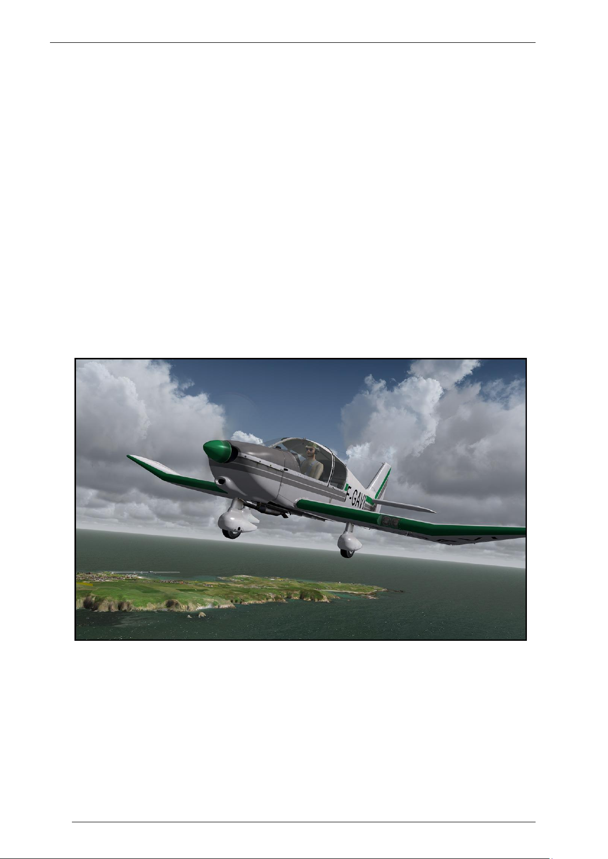
In FSX and Prepar3D it is an ideal aircraft for beginners as you can cruise around without much hassle. But
experts will like the very advanced flight characteristics that are truly highly accurate. In some of the models
they are so accurate that even they idiosyncrasy of an older aircraft are included. For example the D-EVEM
model that is flown by the main developer has a rather serious tendency to turn left. On most models this is
countered by a trim tab but it was not on this model till very recent. So this is one model that is not easy to fly
without rudder pedals. Some other models in this product are better balanced and easier to fly. But it shows
how detailed the actual aircrafts are modelled.
SY S T E M R EQUIREMENTS
Windows XP, Vista, 7, 8 (fully updated)
Microsoft Flight Simulator FSX (with SP2 or Acceleration Pack) or Prepar3D
Dual Core CPU
2 GB RAM internal memory
512 MB graphic card
Adobe Acrobat® Reader 8 minimal to read and print the manual (
(1) Available for free, download at: http://www.adobe.com/prodindex/acrobat/readstep.html
1
)
CREDI TS
Concept: Joachim Schweigler (specific - 3d - design)
Models/Textures: Joachim Schweigler (specific - 3d - design)
XML/ gauges: Finn Jacobsen (Aerosoft), Joachim Schweigler (specific - 3d - design)
Flight mechanics: John Cagle
Flight mechanics proving: Joachim Schweigler (specific - 3d - design)
Project Management: Joachim Schweigler (specific - 3d - design), Mathijs Kok (Aerosoft),
Manual, documentation: Mathijs Kok (Aerosoft)
Sounds: Joachim Schweigler (specific - 3d - design)
Installer: Andreas Mügge (Aerosoft)
Testing: Several good folks who will all be getting a free copy
Page 3
Page 4

Aerosoft Robin DR400 140 1.00
COPY R I G H T S
The manual, documentation, video images, software, and all the related materials are copyrighted and cannot
be copied, photocopied, translated or reduced to any electronic medium or machine legible form, neither
completely nor in part, without the previous written consent of AEROSOFT. THE SOFTWARE IS FURNISHED «AS
IS» AND IT DOES NOT COME FURNISHED WITH ANY GUARANTEE IMPLICIT OR EXPRESS. THE AUTHOR DECLINES
EVERY RESPONSIBILITY FOR CONTINGENT MALFUNCTIONS, DECELERATION, AND ANY DRAWBACK THAT
SHOULD ARISE, USING THIS SOFTWARE.
Copyright © 2013 AEROSOFT. All rights reserved. All trademarks and brand names are trademarks or
registered trademarks of the respective owners.
Copyrights are serious stuff. If you find any pirated copies of this software please notify us at
info@aerosoft.com. We will make sure reports of copyrights violation are rewarded.
Aerosoft GmbH
Lindberghring 12
D-33142 Büren, Germany
www.aerosoft.com
www.aerosoft-shop.com
CONTACT S U P PORT
Support for this product is offered by Aerosoft. We prefer to have a support forum for the simple reason that it
is fast and efficient because customers help customers when we are sleeping.
http://forum.aerosoft.com/index.php/forum
If you prefer email support use this: https://aerosoft.zendesk.com/anonymous_requests/new, do not forget to
add screenshots if they are needed to explain the issue.
We feel strongly about support. Buying one of our products gives you the right to waste our time with
questions you feel might be silly. They are not.
THE M A N U A L S
This English manual you are now reading should be considered the main manual. But for German users we
have a complete actual manual of the D-EVEM as a separate file as well!
FLY I N G T H E R O BI N
The Robin DR400 is an easy aircraft to fly. It’s one of those aircraft that people start to love after getting
acquainted with the few faults it has. It’s stable, reliable and predictable. Predictable even in its ‘problems’, for
example it has a tendency (some even a strong tendency) to want to go left. You sure learn to use the rudder
in this aircraft! The engine is more than powerful enough for the 1000 Kg even though some are 35 years old.
As the fuselage is made of wood it does not have rivets to cause drag and the whole aircraft is very smooth.
The shape of the wing with the characteristic bend halfway helps you to stay out of problems. . In FSX this is an
ideal aircraft for people who want to learn to fly better and to take some trips to scout the virtual landscape
But it is also an ideal trainer as it needs the pilot to fly it all the time, when you look around at the scenery (you
have wonderful visibility in the Robin) it tends to wonder off, no matter how much you trim, it will always find
one direction it wants to go for some reason. So while it may not be the ideal aircraft for long distance travel it
will get you to where you want to do without trying to kill you the way some aircraft seem to want to do. Keep
your energy up, stay ahead of the aircraft and you’ll be fine.
Page 4
Page 5
Aerosoft Robin DR400 140 1.00
There is one thing you should not do however and that’s slip while pulling the nose up. The fuselage will block
airflow over the most effective part of the wing and things can get exciting rather fast.
As said flying the Robin is not hard, here is a highly condensed version of the normal procedures:
Take off from asphalt: flaps in, full throttle, rotate around 100, take of at 120, climb at 150
(or with an even easier method: flaps in, full throttle, rotate at 130, climb at 150)
Take off from grass or short take off: flaps 1, full throttle, pull to unload the nose wheel, lift off,
accelerate, climb with 130
Cruise flight: RPM as needed (max 75% power), lean mixture!
Landing: flaps full, aproach speed 130-140, after touch down ’plant’ the nose wheel down (to unlock
it).
Some peculiarities:
RPM indicator in the D-EVEM shows red line @ 2500. This was the actual situation when the sim
model was released. It is due to noise reduction in the Netherlands (where it was registrated as PHSRW) and has nothing to do with the engines limits
Fuel gauge reads 0 when fuel tank is 100% full. Something weird on some Robins. When fuel level
sinks, the gauge begins to work.
Page 5
Page 6
Aerosoft Robin DR400 140 1.00
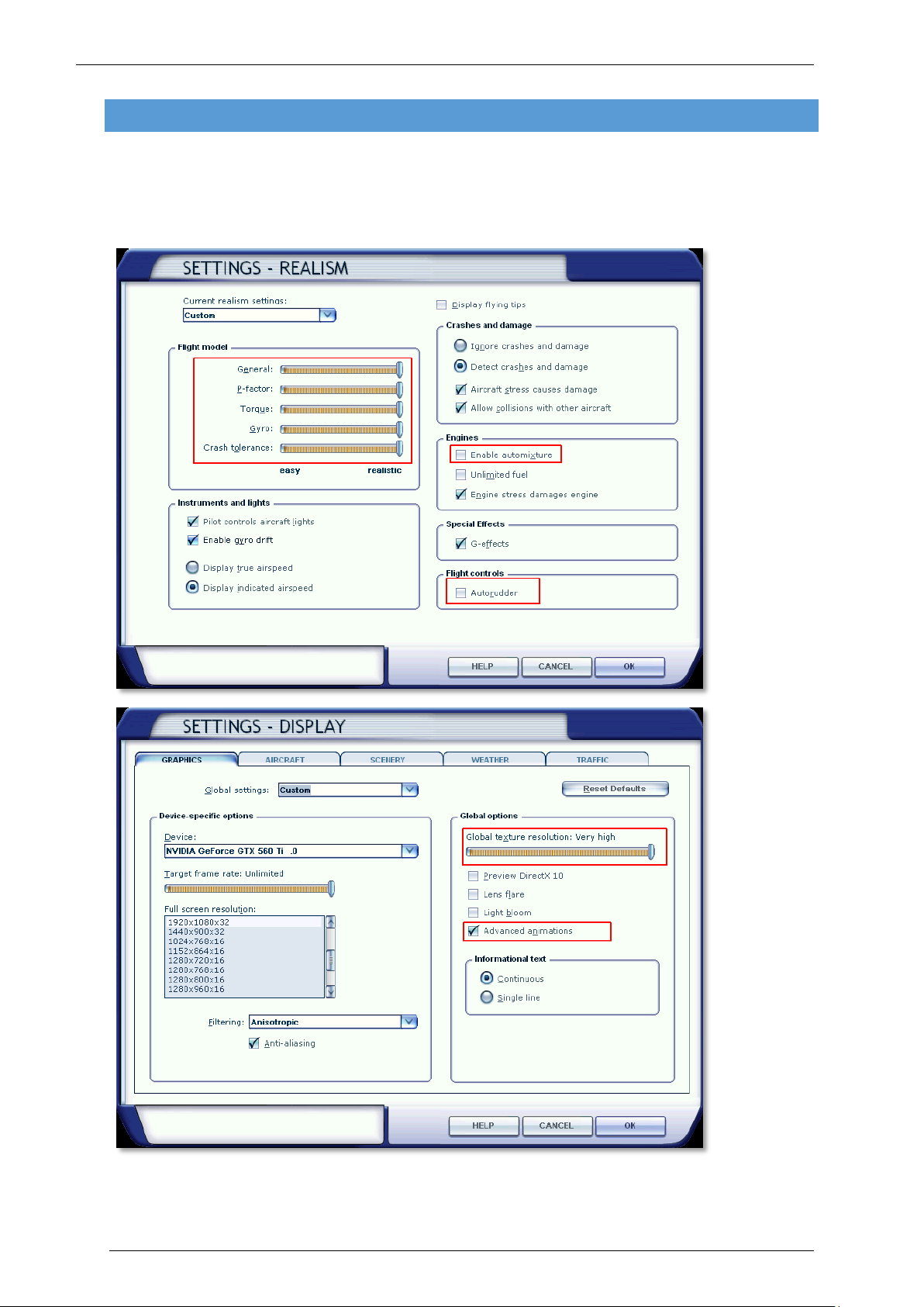
THE R O B I N D R 4 0 0 IN FSX
There are three different Robin DR400 included in this package (different cockpit layouts) and seven different
liveries. You will find them all under Aircraft manufacturer Avions Pierre Robin.
There are a few settings that are very important for this project, they are shown in red in the images below:
Page 6
Page 7

Aerosoft Robin DR400 140 1.00
THE A I R C R A F T
GENE R AL
Wingspan (m) 8,72
Length (m) 6.96
Height (m) 2.23
FLAP S
The flaps (0.669 m2) are controlled with a lever between the two front seats and can be set in three (locked)
stages;
0°
15° (intended for short take offs)
60° (intended for landing)
ELEVA T O R
The balanced elevator (2.88 m2) is controlled by cables and includes Anti-Balance-Trim-Tabs that can be used
as trim surfaces by means of a control wheel between the two front seats.
RUDDER
The conventional rudder (0.63 m2) is controlled via pedals and cable
GEAR
The fixed three wheel gear consists of three identical wheels and uses an oleo pneumatic suspension with long
travel. The Robin can be flown with the wheel covers removed but this dramatically increases drag. The nose
wheel is steerable using the rudder pedals but locked in central position in flight.
BRAK E S
The two main wheels use independent brake circuits for controlling via rudder pedals (last 10% of travel). The
hand/parking-brake brakes both main gear wheels.
ENG I NE / OIL
Engine: Lycoming 4 cylinder air cooled boxer engine (type 0-320-D)
Max RPM: 2700
Compression: 8.5/1
Highest Cylinder Head Temp: 260°
Highest Cylinder Temp: 160°
Rotation: Clockwise
Ignition Order: 1-3-2-4
Oil Pressure Idle: 1,75 bar
Oil Pressure Normal: 4,2 <> 6,3 bar
Max Oil Temp: 118°
ELECT R I CITY
An engine driven generator provides 12 volts for the aircraft systems and charges the 12 volt battery.
Page 7
Page 8

Aerosoft Robin DR400 140 1.00
Bank Angle
0°
30°
60°
Flaps in
99
106
140
Flaps setting 1
93
99
131
Flaps setting 2
87
93
123
FUE L
Fuel Pressure Maximal: 0,560 bar
Fuel Pressure Optimal: 0,210 bar
Fuel Pressure Minimal: 0,035 bar
Tank: 110 L (last 10 L only usable in level flight)
Fuel is fed from the aft tank with an electrical fuel pump to an engine driven fuel pump to provide correct fuel
pressure during all flight conditions.
MAXI M U M SPEEDS
Vne (Maximum Speed): 308 km/h
Vno (Max Speed in rough air): 260 km/h
Vc (Maximum Manoeuvre Speed): 215 km/h
Vfe (Maximum Speed Flaps): 170 km/h
MAXI M U M W EIGHTS
Take off: 1000 kg
Landing: 1000 kg
Luggage Compartment: 40 kg
ALLOW E D M A NOEUVRES
These manoeuvres were allowed when the aircraft were younger but these days only stalls are possible. In FSX
you can take a little risk! As long as the aft seats are not used and the entry and exit speeds are within
maximum allowed limits you should be fine.
Steep turns
Lazy Eights
Chandelles
Stalls
Spins are not allowed!
MAXI M U M C ROSS WIND
Maximum demonstrated cross wind 40 km/h (25 mph/22kts)
STA L L S P EEDS
IAS in km/h
Page 8
Page 9

Aerosoft Robin DR400 140 1.00
EME R G E N C Y P R O C E DURES
ENG I NE FIRE IN FLIGHT
Close fuel selector
Use remaining fuel (full throttle)
Ignition off
Before landing Master off and Generator off
Note that stall warning will not function
ENG I NE FIRE ON GROUND
Do not open engine cover
Use fire extinguisher through exhaust and air inlet
GENE R ATOR FAILURE
When the Ampere indicator shows discharging (The engine will continue to work):
Check generator circuit breaker
Reduce use of anything that uses electricity
ICI N G
When RPM drops unexpectedly:
Carburettor heat to full
Full throttle
Seek for non-icing conditions (descend into warmer air)
Expect RPM to drop by 150 RPM and an increase of fuel use.
EMERG E N CY LANDING
Check safety belts
Close fuel selector to reduce fire risk
IN C A S E OF INVOLUNTARY SPIN
Elevator and Aileron to neutral
Rudder opposite spin direction
Flaps in
Page 9
Page 10
NORM A L F L I G H T PROCEDURES
FLIG H T PREPARATION
1. Before flight check that all weight and balance are within allowed limits.
Aerosoft Robin DR400 140 1.00
Page 10
Page 11
Aerosoft Robin DR400 140 1.00
Page 11
Page 12

BEFO R E FLIGHT CHECKS
1. Master switch on
2. Check fuel quantity
3. Master off
4. Ignition off
5. Fuel selector on
6. Mixture full lean (pulled)
BEFO R E ENGINE START
1. Adjust seat and seatbelt
2. Cabin closed and locked
3. Check rudder travel
4. Parking brakes on
5. Master switch on
6. Trim neutral
7. Mixture full rich (pushed)
8. Carburettor heat off (pushed)
9. Fuel selector open
10. Flaps extend
Aerosoft Robin DR400 140 1.00
ENG I NE START
1. Electrical pump on
2. Generator on
3. Ignition to both
4. Start engine
5. Ignition to both
6. Keep RPM as low as possible but increase till engines runs smooth
TAX I
1. Lock brakes and open throttle to see if the nose moves up and down
2. Release parking brakes
3. Avoid riding the brakes and sudden turns
4. Normal RPM for taxi 1200 RPM
5. Avoid overheating the engine
BEFO R E START
1. When needed (winter) warm up engine at 1200 RPM
2. Do not use full power
3. Check magneto’s at 1800 RPM, maximum 125 RPM between sides.
4. Switch ignition momentarily off at 1000 RPM to check functionality
5. Check instruments and radio
Page 12
Page 13

STA R T
1. Carburettor heat off
2. Mixture full rich (pushed)
3. Slow increase throttle to full
4. Check RPM (2200) and abort when RPM too low
5. Keep pressure on nose wheel to allow directional control
6. Lift off at 100 km/h
7. Increase speed
8. Climb at 120 km/h
STA R T IN CROSSWIND
1. Use rudder to compensate for wind
2. Use higher speed for lift off
3. Avoid ground contact after lift off
4. Steer into wind to counter drift
CLIM B
Obstacle avoidance: climb at 130 km/h with first stage flaps
Aerosoft Robin DR400 140 1.00
1. Flaps in
2. Full throttle
3. Maintain 150 km/h
4. Set trim
5. Electrical pump off
Avoid extended maximum climb angle to avoid overheating
CRUI S E
1. Use throttle to set engine output
2. Set trim
3. Decrease mixture till engine sound rough then increase to smooth
4. Set mixture after each altitude or RPM change
DESC E N T
1. Carburettor heat on
2. Decrease engine RPM
3. Decrease airspeed
4. Electrical pump on
5. Mixture full rich
6. Under 170 km/h use flaps when needed
7. Set trim
When in a long descent use short bursts of throttle to avoid the engine cooling down too much.
Page 13
Page 14

LAND I NG
1. Approach speed: Vi = 1,3 x stall speed (example 115 km/h at 1000 kg)
2. Carburettor heat full
3. Mixture full rich
4. In strong winds control speed carefully
ABO R T E D L ANDING
1. Full throttle
2. Carburettor heat off
3. Flaps to start setting as soon as possible
LAND I NG IN CROSSWIND
1. Lower upwind wing
2. Level wings just before landing
3. Use pedals to control direction
AFT E R L ANDING
Retract flaps during taxi
Extend flap on parking to avoid damage
Set parking brake
1200 RPM
Check both magnetos
Mixture to full lean to stop engine
Master switch off
Fuel selector off
Aerosoft Robin DR400 140 1.00
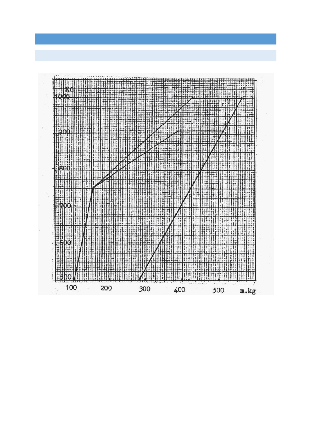
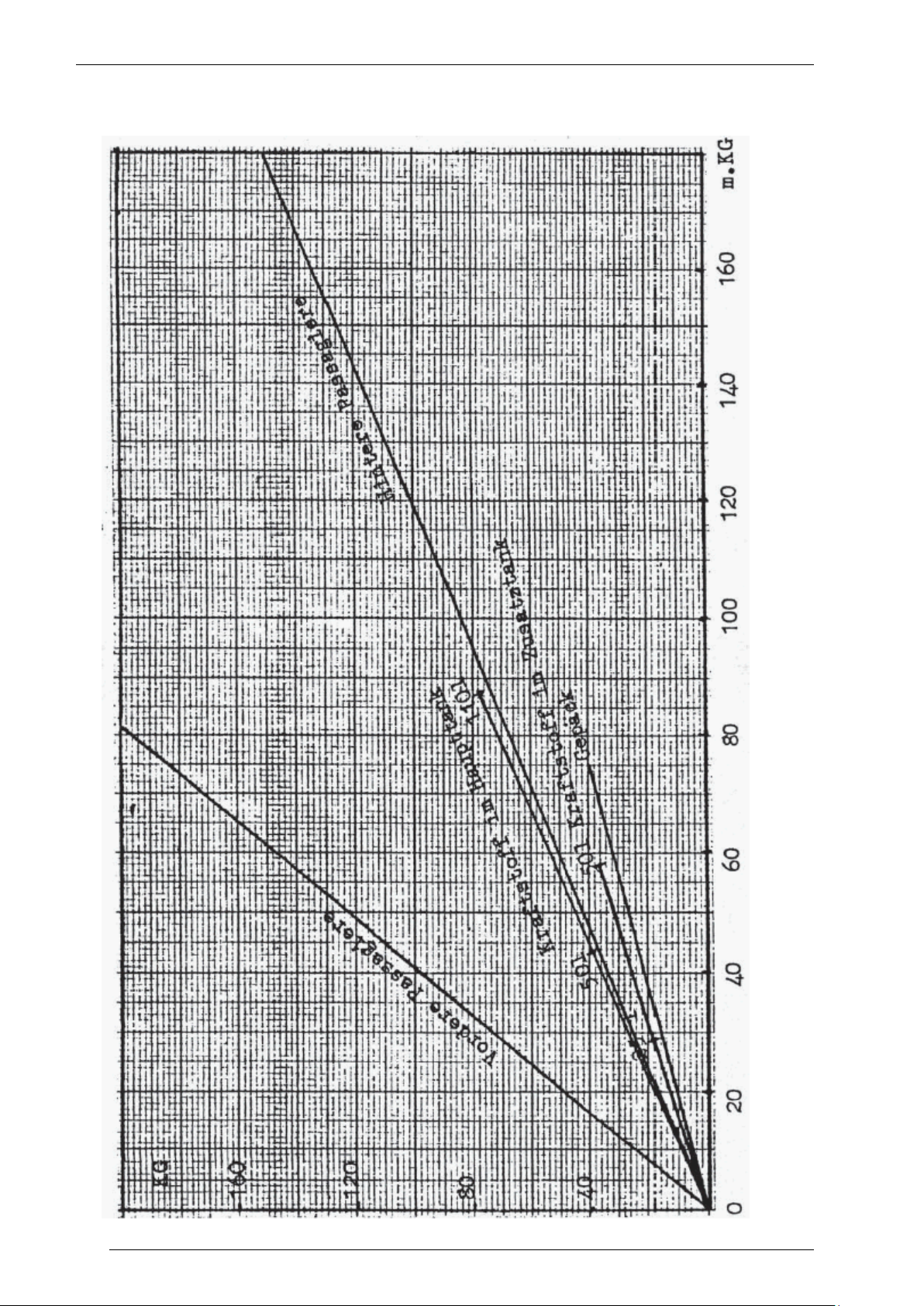
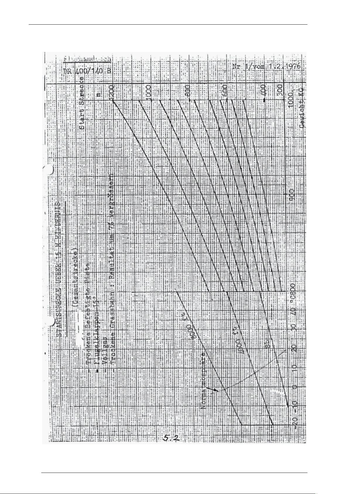
PERF O R M A N C E C HARTS
The following pages include the performance charts as they are provided for the German Robin DR400 we
used as the base for the simulated aircraft. The charts are in German but should be usable if you do not read
that language. Or as the developer told me, “it’s not like the real aircraft cares a lot about these charts.”
Do not get too focussed on performance charts, the DR400 will tell you what it can do, just fly it and listen to
what it tells you.
Page 14
Page 15
Aerosoft Robin DR400 140 1.00
Page 15
Page 16

Aerosoft Robin DR400 140 1.00
Page 16
Page 17

Aerosoft Robin DR400 140 1.00
Page 17
Page 18

Aerosoft Robin DR400 140 1.00
Page 18
Page 19

Aerosoft Robin DR400 140 1.00
1
Throttle
20
Ignition
2
Airspeed indicator
21
Starter
3
Artificial Horizon
22
Battery switch
4
Altimeter
23
Generator switch
5
ADF gauge
24
Mixture control
6
Turn and bank indicator
25
Heating control
7
Gyro
26
Heating for/aft
8
Vertical Speed Indicator
27
Defroster
9
VOR gauge
28
Carburettor heat
10
Suction Indicator
29
Fuel pump
11
GPS
30
Nav / Beacon Light
12
Com-Nav
31
Panel Light
13
Transponder
32
Trim indication
14
RPM indicator
33
Parking brake
15
Cylinder Head Temp
34
Fuel selector
16
Fuel Quantity
35
Stabilizer trim
17
Oil Temperature
36
Checklist / State select
18
Ampere indicator
37
Flaps lever
19
Landing Lights
PANELS L A Y O UT
Although all three panels differ slightly the same element can be found in all the cockpits.
When clicked the checklist will move to your left hand. When you right click
on the opened checklist it will flip and you can use the left mouse button to
select a ready to fly configuration or a cold and dark configuration. A right
mouse click will flip the page again.
Note that two of the models have an ADF receiver where the model shown above has the GPS device.
Page 19
Page 20
Aerosoft Robin DR400 140 1.00
AVI O N I C S
MOVM A P 7 54 GPS UNIT
Several of the cockpits are equipped with a GPS that is modelled on well-known GPS devices. The GPS
instrument has its own internal battery so it can be used when the Master switch is still off. It’s charged by the
Primary DC electrical bus when the Battery master switch is on. To turn the GPS on, press the button with the
red logo and the start-up screen will be displayed.
CAUTION: The framerate of the sim is affected by the amount of details shown!
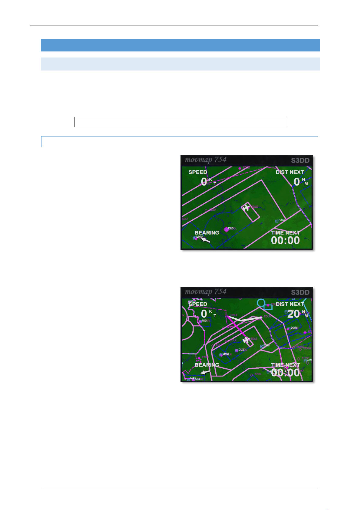
MAP M O D E
After initialization the GPS will be in Map Mode
showing an aircraft symbol in the centre of a map.
North is always up. In the four corners of the
display, current ground speed, distance to next
waypoint, estimated time to next waypoint and a
pointer depicting relative bearing to the next
waypoint are shown. If the pointer points up, the
aircraft is heading straight towards the next
waypoint. Use the IN / OUT buttons to zoom the
map in or out. The GPS can show Airports, VOR’s,
NDB’s, Intersections and Airspace boundaries. To
toggle the display of these items press the MENU
button and use the UP / DOWN cursor key (the
large button) to highlight the Class (Airport, VORs, NDBs, Intersection or Airspace). Use the LEFT / RIGHT cursor
key to toggle the display of these items. Use the QUIT button to return to the MAP page.
Standard FSX flight plans can be loaded via the
normal FSX dialog and will be automatically
displayed on the MAP page.
Page 20
Page 21

DIRE C T T O MODE
Using the GOTO button will allow the input of a
DIRECT TO location. Use the UP / DOWN cursor keys
to change the character on the blinking field. Use
the LEFT / RIGHT cursor key to move to the next or
previous field. Enter an ICAO identifier for airport,
VOR or NDB.
NOTE: Intersections are not supported in the GOTO mode.
Once an identifier is recognized, it will show facility
name and nearby city – if possible. Press ENTER and
the GPS will return to the Map mode with the flight
plan leg from the current aircraft position to the
selected identifier. As everywhere using the QUIT
button will halt the action and return to the MAP
screen.
Aerosoft Robin DR400 140 1.00
CUR S O R MODE
Another option to make a DIRECT-TO flight plan, is with the help of the “Cursor Mode”. When the GPS is in
map mode, pressing either the UP / DOWN / LEFT or RIGHT cursor key, will put the GPS into “Cursor mode”. A
small cursor (blinking circle) will appear instead of the aircraft symbol. Using the cursor keys the circle can be
moved on the map and the map will centre on the cursor position. A line will be drawn from the current
aircraft position to the cursor.
Press ENTER to select the cursor position as a
Direct-To flight plan. If the ENTER button is not
pressed within a few seconds or by pressing QUIT,
cursor mode will be suspended and the GPS will
return to Map mode. By using the cursor mode any
global position can be selected as a waypoint. This
is the easiest way to make a very simple flight plan,
certainly if the desired waypoint isn´t too far away.
In cursor mode finer adjustments can be made by
zooming in on the map first.
Page 21
Page 22

Aerosoft Robin DR400 140 1.00
NE A R E ST STATION
Using the NRST button will open the NEAREST
STATION list and the LEFT / RIGHT cursor keys will
change between Airports, VORs, NDBs and
Intersections. Use the UP / DOWN cursor keys to
highlight an identifier and press ENTER to select it
as DIRECT-TO, or press QUIT to cancel the selection.
HSI P AGE
Pressing the ENTER key while being in Map mode
will bring up the HSI page. The HSI page shows:
Compass rose, showing ground track,
which is the true track over ground, taking
crosswinds and sideslip into account. It
does NOT show magnetic nor true heading,
like a normal gyro based HSI.
Course Needle, showing the active flight
plan leg bearing.
Course deviation indicator bar (middle part
of the Course needle), showing the cross
track error. Each dot represents 1 nautical
mile.
TO/FROM flag showing the position
relative from the active flight plan leg.
Right part of the screen shows Ground speed, Distance to next waypoint, Ground track (same as
Compass rose) and next waypoint bearing.
If the Ground track value and the Bearing value are equal, this indicates that the aircraft is heading straight
towards the next waypoint, but not necessarily following the flight plan leg.
Page 22
Page 23

HSI SAMPLES:
On track direct towards the active waypoint, TO / FROM flag shows TO:
Aerosoft Robin DR400 140 1.00
Correct heading but about 2 miles left of the flight plan leg:
Still 2 miles left of the flight plan leg, but on an intercept heading of 40°:
Page 23
Page 24

Aerosoft Robin DR400 140 1.00
Flight plan leg behind the aircraft, note the TO/FROM flag has changed to FROM:
Still behind the flight plan leg, but heading towards the waypoint. The Flag still shows from. Use “bearing” in
this case to get to the waypoint, keeping the ground track equal or the same.
S3DD AI R M AP GPS
Some models come with a small GPS device that is modeled after the popular Garmin GPS III. This instrument
has its own internal battery so it can be used when the Master switch is still off. It’s charged by the main
electrical bus when the Master switch is on.
To turn the GPS on, press the button with the red logo. The start-up screen appears
Note, the backlight can be turned on with right click on the red button.
MAP M O D E
After initialization the GPS will be in Map Mode:
On the left 2/3 part of the display a map is
drawn, showing the current position with an
aircraft symbol. North is always up. On the right
1/3 part of the display, current ground speed,
distance to next waypoint, estimated time to
next waypoint and a pointer depicting relative
bearing to the next waypoint is shown. If the
pointer points up, the aircraft is heading straight
towards the next waypoint. Use the IN / OUT
buttons to zoom the map in or out.
Page 24
Page 25

Aerosoft Robin DR400 140 1.00
The GPS can show Airports, VOR’s, NDB’s,
Intersections and Airspace boundaries. To toggle
the display of these items press the MENU
button. The Setup page will now be shown:
Use the UP / DOWN cursor key (the large button)
to highlight the Class (Airport, VORs, NDBs,
Intersection or Airspace). Use the Left / Right
cursor key to toggle the display of these items.
Use the QUIT button to return to the MAP page.
Note: the framerate of the simulator is affected by the amount of information shown!
Standard FSX flight plans can be loaded via the
FSX dialog and will be displayed on the MAP
page.
Page 25
Page 26

DIRE C T T O
Using the GOTO button will allow the input of a
DIRECT TO location.
Use the UP / DOWN cursor keys to change the
character on the blinking field. Use the LEFT /
RIGHT cursor key to move to the next or
previous field. Enter an ICAO identifier for
airport, VOR or NDB.
Aerosoft Robin DR400 140 1.00
Note: Intersections are not supported in the GOTO mode.
Once an identifier is recognized, it will show
facility name and nearby city - if possible. Press
ENTER and the GPS will return to the Map page
with the flight plan leg from the current aircraft
position to the selected identifier. As everywhere
using the QUIT button will halt the action and
return to the MAP screen.
Page 26
Page 27

Aerosoft Robin DR400 140 1.00
CUR S O R M OD E
Another option to make a DIRECT-TO flight plan,
is with the help of the “Cursor Mode”. When the
GPS is in map mode, pressing either the UP /
DOWN / LEFT or RIGHT cursor key, will put the
GPS into “Cursor mode”. A small cursor (blinking
circle) will appear instead of the aircraft symbol.
Using the cursor keys the circle can be moved on
the map and the map will center on the cursor
position. A line will be drawn from current aircraft
position to the cursor.
Press ENTER to select the cursor position as a
Direct-To flight plan. If the ENTER button is not
pressed within a few seconds or by pressing QUIT, cursor mode will be suspended and the GPS will return to
Map mode. By using the cursor mode any global position can be selected as a waypoint. This is the easiest way
to make a flight plan, certainly if the desired waypoint isn´t too far away.
TIP: In cursor mode finer adjustments can be made by zooming in on the map first.
NE A R E ST STATION
Using the NRST button will open the NEAREST
STATION list:
The LEFT / RIGHT cursor keys will change
between Airports, VORs, NDBs and Intersections:
Use the UP / DOWN cursor keys to highlight an
identifier and press ENTER to select it as DIRECTTO, or press QUIT to cancel the selection.
Page 27
Page 28

Aerosoft Robin DR400 140 1.00
HSI P AGE
Pressing the ENTER key while being in Map mode
will bring up the HSI page.
The HSI page shows:
Compass rose, showing ground track,
which is the true track over ground,
taking crosswinds and sideslip into
account. It does NOT show magnetic nor
true heading, like a normal gyro based
HSI.
Course Needle, showing the active flight
plan leg bearing.
Course deviation indicator bar (middle
part of the Course needle), showing the cross track error. Each dot represents 1 nautical mile.
TO/FROM flag showing the position relative from the active flight plan leg.
Right part of the screen shows Ground speed, Distance to next waypoint, Ground track (same as
Compass rose) and next waypoint bearing.
If the Ground track value and the Bearing value are equal, this indicates that the aircraft is heading straight
towards the next waypoint, but not necessarily following the flight plan leg.
HSI S A M P L ES
On track direct towards the active waypoint, TO / FROM flag shows TO.
Correct heading but 3 miles left of the flight plan leg:
Still 3 miles left of the flight plan leg, but on an intercept heading of 40°
(Note Ground track and Bearing readings):
Flight plan leg behind the aircraft, note the TO/FROM flag has changed to FROM:
Page 28
Page 29

Aerosoft Robin DR400 140 1.00
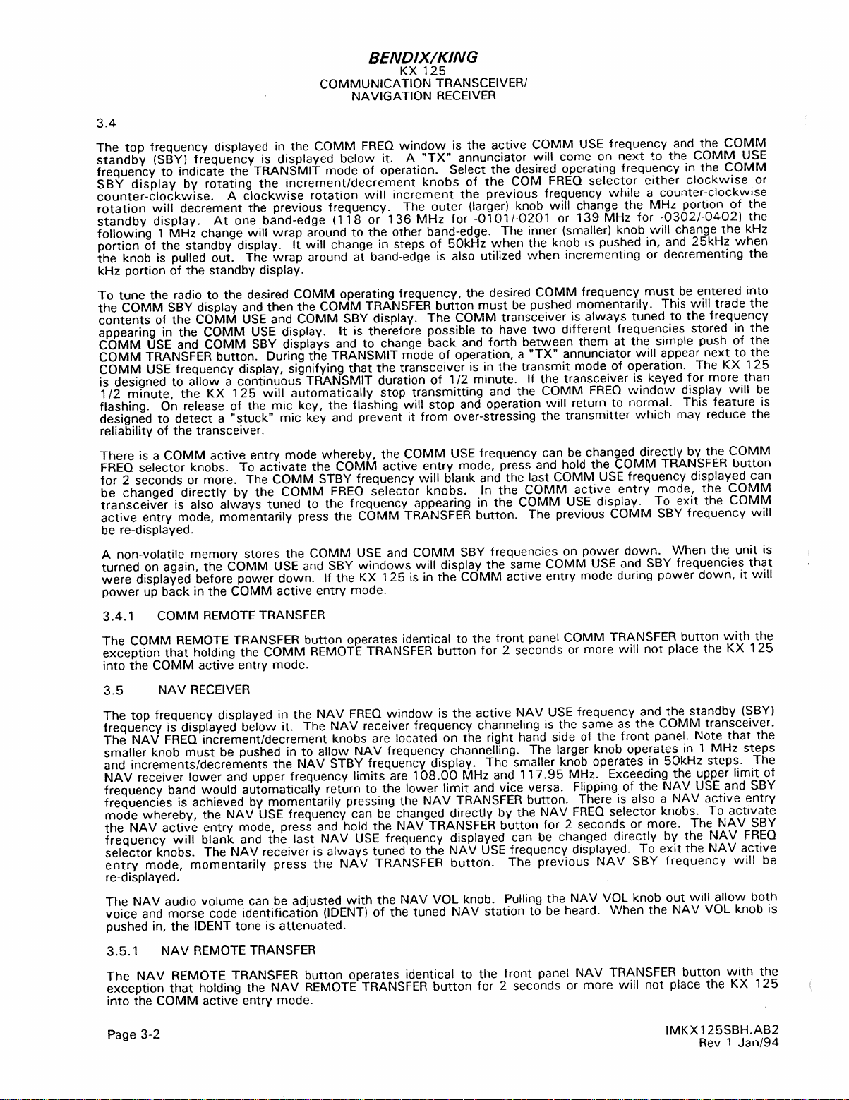
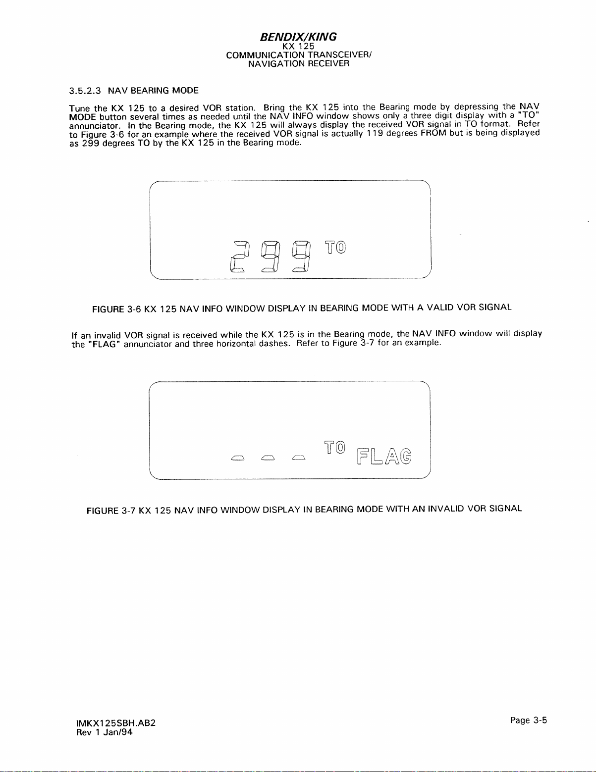
BEND I X / K ING KX125 COMMUNICATION T R A NSC EI V E R
The KX125 is a useful but slightly antiquated communication and navigation radio. As this instrument is
carefully simulated we include the actual manual as an appendix to this manual.
BECK E R T RANSPONDER
The Becker BXP 6401 transponder is a Mode S transponder which enables ATC to locate, identify and track the
aircraft by responding to ATC radar interrogations. In Mode S it will conduct altitude reporting, used by other
aircrafts TCAS systems for collision warnings. Remember to turn the Transponder to STDBY after landing when
leaving the runway.
To set the transponder push the right rotary button to select the first digit, then turn. Press it again to select
the second digit etc. Press [VFR] to directly select 7000.
Page 29
Page 30

Page 31
Page 32

Page 33

Page 34
Page 35

 Loading...