

Page 1
Add-on for Microsoft
Flight Simulator
And FS2004!
With realtime Vatsim
and IVAO Traffi c!
Manual
Page 2

FSMap
Concept, Development and Programming
Thomas Molitor
Documentation
Martin Georg and Thomas Molitor
Additional Control Programming
Dirk Bunar (Tribe Technology)
ICAO VFR Maps
Deutsche Flugsicherung GmbH (DFS)
Skyguide und swisstopo
Global Maps
NASA‘s Earth Observatory
Copyright: © 2008 / Aerosoft GmbH
Airport Paderborn/Lippstadt
D-33142 Bueren, Germany
Tel: +49 (0) 29 55 / 76 03-10
Fax: +49 (0) 29 55 / 76 03-33
E-Mail: info@aerosoft.de
Internet: www.aerosoft.de
www.aerosoft.com
All trademarks and brand names are trademarks or
registered trademarks of their respective owners.
All rights reserved.
Aerosoft GmbH 2008
2 3
Page 3

FSMap
Add-on for
Microsoft Flight Simulator X
Manual
Page 4

FSMap
Content
Introduction ......................................................................6
FSMap Basics .....................................................................7
The external „FSMap Application“ .................................... 7
The FSMap gauge ...............................................................8
FSMap charts ....................................................................... 8
Installation .......................................................................9
Installing and configuring SimConnect ........................... 14
Installing and using WideFS ............................................17
Overview - FSMap application ......................................19
FSMap Menu Structure.....................................................23
Quickstart guide .............................................................26
Manage Maps..................................................................27
Add new maps .................................................................. 28
Import Map ....................................................................... 34
Export maps ......................................................................35
Aerosoft GmbH 2008
4 5
Page 5

Manage Gauge ................................................................36
Adding or updating the FSMap gauge file ..................... 37
Remove FSMap gauge from Flight Simulator................. 38
Add a hotspot to a panel .................................................38
Adding and removing the FSMap instrument to/from a
panel .................................................................................. 39
Define the FSMap instrument hotkey ............................. 40
Edit the FSMap instrument properties ............................ 41
The FSMap application as a moving map .....................43
Connect FSMap to MS Flight Simulator .......................... 43
Loading a flight plan ........................................................44
Map display configuration ............................................... 44
The FSMap Instrument/Gauge .......................................49
The FSMap instrument menu system .............................. 51
The FSMap instrument as a moving map ....................... 55
The FSMap instrument as a TCAS display ....................... 58
Credits .............................................................................62
Chart resources ...............................................................63
Map legend ICAO-Charts................................................65
FSMap Keyboard- Reference ..........................................69
Page 6

FSMap
Introduction
During the past couple of years, electronic navigation aids started to
revolutionize aviation. Digitized charts, together with high-resolution
displays and the ability to define your own position precisely via GPS,
are the technological fundament, to have aeronautical information
present even in general aviation aircraft.
Now FSMap brings a realistic simulation of one of the leading devices
in this area to flight simulation. With FSMap you will get high-resolution
digitized VFR charts for Germany, Austria, Switzerland and the Benelux
countries. More charts can be added easily by using the integrated
chart editor and configurator. A sophisticated layering system ensures
that you will always see the appropriate chart for the current flight
phase and mode. But FSMap not only displays charts, it also supplies
the virtual pilot with a wealth of information about his flight route,
flight status, AI- and multiplayer traffic, and environmental conditions.
And while you are taxiing on the ground, FSMap can even display
taxiways and parking positions straight out of flight simulator data.
By using the supplied panel editor, the FSMap gauge may be added
to any instrument panel with a few mouse clicks. Besides the supplied
gauge, you may also use FSMap as an external application outside
Flight Simulator. By using FSUIPC (for FS2004) or SimConnect (for FSX),
users may even utilize a second PC in their home network to run the
FSMap application.
And now we wish you pleasant hours of flying with FSMap. Keep the
blue side up!
The FSMap development team
Aerosoft GmbH 2008
6 7
Page 7

FSMap Basics
FSMap consists of two major parts: The external application, called
„FSMap Application“, and the „FSMap Gauge“, which is to be used
from withing MS Flight Simulator. Some functions of both overlap,
while others don´t.
The external „FSMap Application“
One of the core functions of the external applications is to configure
and manage your installed set of charts. You will find routines to
select, calibrate, and define their use. For further information about
chart management, refer to chapter „Chart Management“ later in this
manual. Furthermore, the FSMap Application is used to add the FSMap
Gauge to instrument panels, add and remove hotspots (hidden click
zones) and toggle icons. For this purpose a comfortable panel editor is
included in the application. Customers who are familiar with our „FS
Flight Keeper“ program may be already used to our panel editor.
Besides its use as a chart and panel editor and configurator, the FSMap
application also functions as a full-featured moving map. To connect
to MS Flight Simulator, the FSMap application uses either FSUIPC (for
Flight Simulator 2004) or SimConnect (for Flight Simulator X). FSMap
Application may be run on a separate PC in a local network, thus
freeing your Flightsim PC from running FSMap and therefore conserving
valuable performance resources.
A few functions in the external FSMap application (such as displaying
online ATC presence) are not available in the gauge variant. Also,
updating the navigation database requires the use of the external
application.
Page 8

FSMap
The FSMap gauge
The FSMap gauge has to be integrated into flight simulator instrument
panels directly. From there it can be opened by clicking on a hotspot,
or using a key combination. Depending on your preferences, the FSMap
gauge may be opened as an own panel sub window, or integrated into
an existing panel view.
The FSMap gauge has some unique features, which are not available
in the external application. Among these are the ability to display
airport layouts, including taxiways and parking positions. Also, you
may configure the FSMap gauge thread to run on a specified core in a
multi-core CPU system.
FSMap charts
FSMap supports charts in several different graphics formats. You may
use JPG, PNG, TIFF, BMP and GIF files with all possible colour depths.
The maximum graphics size allowed by the FSMap application is 8.000
x 8.000 pixel, the gauge supports graphics with a maximum of 5.000 x
5.000 pixels. We highly recommend, however, to keep your chart files
smaller, or spread them across several individual files. Smaller files will
be loaded much faster, and they also reduce the amount of memory
used to display them. For the same reason it is recommended to keep
the color depth at 8 bit. For aeronautical charts, this is a sufficient
quality, and furthermore it also cuts down memory usage.
A map graphic needs to be calibrated before it can be used with FSMap.
For this, FSMap needs to know the type of map projection used (either
„None“ or „Lambert Conic“) and at last two reference points on the
chart, defined by their coordinates. All charts supplied with FSMap are
calibrated already, and may be used without any further preconfiguration.
Other precalibrated charts may be available from download sources in
the internet, check our links section at the end of this manual.
Aerosoft GmbH 2008
8 9
Page 9
Installation
The installation routine will start automatically after the CD has been
inserted into the CD/DVD drive. You need to have „Autorun“ activated
on your computer for this. Check your Windows documentation for
further reference regarding „Autorun“.
FSMap may be installed on the computer running MS Flight Simulator ,
or on any other computer in your local network. To establish
communication with Flight Simulator X over a local network, FSMap
uses „SimConnect“, which is included with MS Flight Simulator.
Connection with FS2004 is done using „FSUIPC“ and „WideFS“ by
Pete Dowson. Both programs need to be bought separately, and are
not part of FSMap. You may get them via http://www.simmarket.com .
When the installer is started, you are greeted with the following dialog
window:
To continue, click on „Next“.
Page 10
FSMap
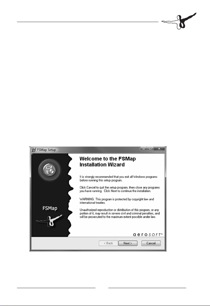
You are now requested to confirm the software license agreement:
Please note that you will need administrator rights to install FSMap.
Please consult your windows documentation about how to get
administrator rights on your computer. The FSMap installation routine
explicitly reminds you of this fact:
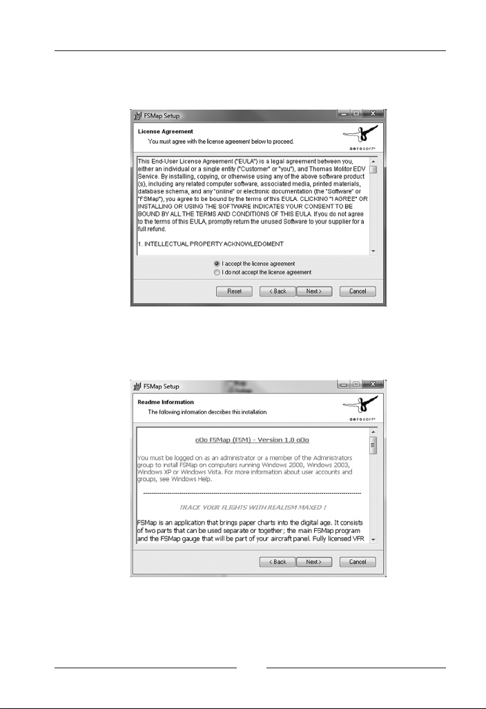
You are now prompted to enter your name and company name. While
the name field is mandatory, the company field may be left blank.
When installing FSMap on Vista, please always install the program for
all users.
Aerosoft GmbH 2008
10 11
Page 11
Otherwise you may run into troubles with Vista´s user account control
(UAC):
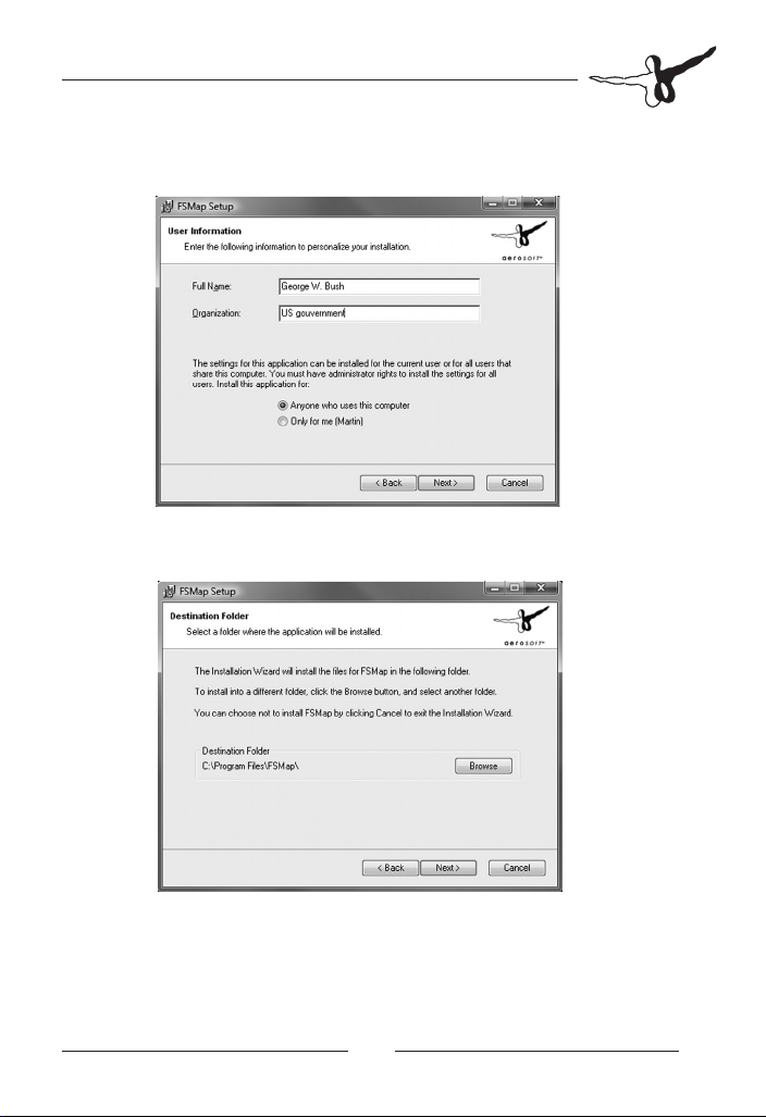
The next dialog presents you with the proposed installation path. We
recommend you to keep this path.
Page 12
FSMap
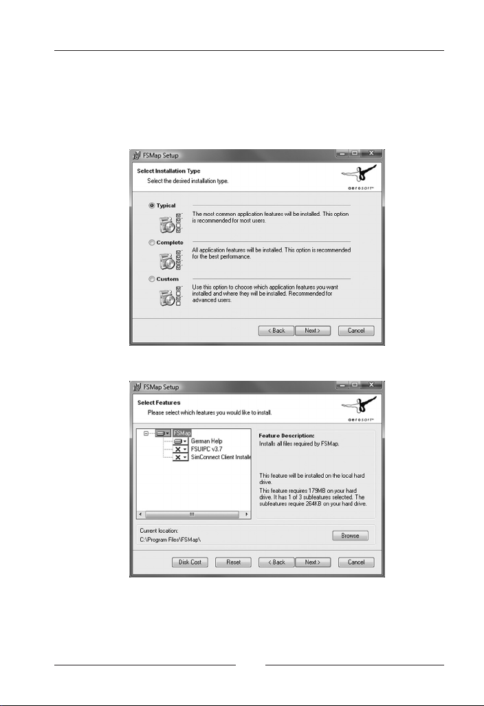
This screen configures how FSMap is installed. You may either choose
to install all files, a typical file set only, or to define by yourself which
parts you want to install. If you want to do the latter, select „Custom“.
We highly recommend to fully install FSMap:
In case you have selected a custom installation, you will now be
prompted with the following dialog:
The installation of “SimConnect“ is only needed if you install FSMap
on a separate computer in your local network, and when you want
to connect to FSX. For connections to FS2004, you will need to install
FSUIPC. Also, you may redefine your installation path, if needed, here.
Aerosoft GmbH 2008
12 13
Page 13
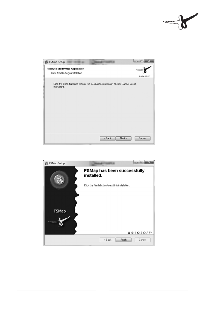
To finish your selection, click on „Next“. If you want to start over again
with the installation process, click on „Back“. When all settings are
correct, click on „continue“ again:
The installer now copies files onto your harddisk. This may take a few
minutes.
The following screen tells you that FSMap has been installed successfully.
To finish the installation, click on „Finish“.
Page 14

FSMap
Installing and configuring
SimConnect
FSMap may be installed and used on a second PC in a local network
(called “network PC” from now”). It will then access FSX on your
flightsim PC (called “FSX PC” from now) using Microsoft’s data interface
“SimConnect”. This chapter will describe the necessary steps to install
and configure SimConnect.
Before installing SimConnect, check that all necessary prerequisites are met:
FSX service pack 1 or newer is installed.•
Both computers (network PC and FSX PC) are configured •
correctly to use the TCP/IP network protocol.
Both PCs should use a fixed IP address.•
Your firewall software needs to be configured to allow data on •
the networking port you will specify to pass through.
FS Map is completely installed and up to date on the network PC.•
FSX may be upgraded with service pack 2 or Acceleration. These •
packages are not necessarily required. We recommend you to
install service pack 2 anyway, as it will correct some other bugs
introduced by Microsoft.
First step is to install the SimConnect client software on the network
PC. The version of the client you need to install varies with the Flight
Simulator revision you’re using. For your convenience we have included
all SimConnect variants in the folder \SimConnect inside the FSMap
main program folder (usually located at C:\Program Files\FSMap). The
sub-folder names will translate as followed: RTM = original release
version, SP1 = Service Pack 1, SP2 = Service Pack 2 or Acceleration.
Launch the respective .msi file on the network PC by double-clicking
on it. The installation will happen automatically.
Next step is to copy and modify a file called SimConnect.XML. A template
for this file is included in C:\Program Files\FSMap\SimConnect. The file
needs to be copied to the following folder on the FSX PC:
Aerosoft GmbH 2008
14 15
Page 15

Windows XP: C:\Documents and Settings\<Your Windows User-
name>\AppData\Microsoft\FSX
Windows Vista: C:\Documents and Settings\<Your Windows
Username>\AppData\Roaming\Microsoft\FSX
SimConnect.XML is a normal text file, which may be edited using any
text editor available (such as Windows Notepad). For each networking
protocol this file includes a section <SimConnect.comm> „Global“
and <SimConnect.comm> „Local“. It will be determined by the entry
<Scope>global</Scope> or <Scope>local</Scope>.
In most cases, you will use the IPv4 protocol, therefore we need to
modify the appropriate sections. The section “global” uses several
parameters, which need to be defined as followed:
Protocol: IPv4 (example: <Protocol>IPv4</Protocol>)
Address: Enter the fixed IP address of your FSX PC here (example:
<Address>192.168.1.100</Address>)
Port: We recommend you to use port 500 (example: <Port>500</Port>)
A complete global section for the IPv4 protocol may read as followed:
<SimConnect.Comm>
<Disabled>False</Disabled>
<Protocol>IPv4</Protocol>
<Scope>global</Scope>
<Address>192.168.1.100</Address>
<MaxClients>64</MaxClients>
<Port>4096</Port>
<MaxRecvSize>500</MaxRecvSize>
<DisableNagle>False</DisableNagle>
</SimConnect.Comm>
Page 16

FSMap
The section “local” should look like this:
<SimConnect.Comm>
<Disabled>True</Disabled>
<Protocol>IPv4</Protocol>
<Scope>local</Scope>
<MaxClients>64</MaxClients>
<Address>127.0.0.1</Address>
<Port>500</Port>
</SimConnect.Comm>
In a final step the file SimConnect.CFG needs to be copied from the
network PC from the folder C:\Program Files\FSMap\SimConnect into
the main program directory of FSMap on the network PC. In addition,
you need to modify the file according to the setting your made in the
SimConnect.XML file earlier.
The file SimConnect.CFG contains multiple sections, with each section
title covered by braces. For our purposes, we just need to modify
the section titled [SimConnect], other sections may be deleted. The
parameters should look like this:
[SimConnect]
Protocol=IPv4
Address=192.168.1.100
Port=500
MaxReceiveSize=4096
DisableNagle=0
Copying the SimConnect.CFG file finishes the configuration of
SimConnect. You may now launch the FSMap application on the
network PC and connect it to a running FSX on your FSX PC.
Aerosoft GmbH 2008
16 17
Page 17

Installing and using WideFS
The product “WideFS” is made up of two primary elements: A flight
simulator module called “WideServer”, and an external application
called “WideClient”. You will receive both components together in
one ZIP-Archive from the Author, or via download from several flight
simulation file archives on the Internet. Before WideFS may be used,
it has to be registered using the serial number provided with the
purchase. This is done from a dialog window of FSUIPC. In order to
use WideFS you need to own a registered version of FSUIPC. Both
products are available for a combined purchase at a reduced price.
WideFS uses the TCP/IP protocol for communication. Please ensure
that both computers (network PC and FSX PC) are configured correctly
to use the TCP/IP network protocol. For details consult your Windows
documentation.
WideFS installation for FS2004
From the WideFS ZIP archive, copy the two files named WIDESERVER.
DLL and WIDESERVER.INI to your MODULES directory, located directly
below the main FS2004 directory. Thereafter, create a folder named
“WideClient” on your network PC in the “Program Files” folder. Copy
the two files named WIDECLIENT.EXE and WIDECLIENT.INI from the
WideFS ZIP archive to this new folder.
WideFS installation for FSX
You can also use WideFS to establish a network connection between
your FSX-PC and your network PC. But as SimConnect is the new
standard interface of FSX we recommend to use SimConnect (read the
chapter „Installing and configuring SimConnect“).
If you still want to use WideFS with FSX please follow the next steps:
WideServer is integrated into FSUIPC version 4, and need to be
activated through FSUIPC. Register WideFS first (see above), then
restart FSX. Thereafter, create a folder named “WideClient” on your
Page 18

FSMap
network PC in the “Program Files” folder. Copy the two files named
WIDECLIENT.EXE and WIDECLIENT.INI from the WideFS ZIP archive to
this new folder.
Using WideFS
To connect FSMap to your flight simulator through WideFS, first launch
Flight Simulator itself, then start the WIDECLIENT.EXE application on
the network PC. Thereafter, launch FSMap. Usually there is no further
configuration work necessary.
WideFS may be configured to work with a wide variety of different
networking configurations and options. For details about how to set
these options please consult the WideFS documentation contained in
the WideFS ZIP file.
Aerosoft GmbH 2008
18 19
Page 19
Overview -
FSMap application
The external FSMap application is a
looks as follows:
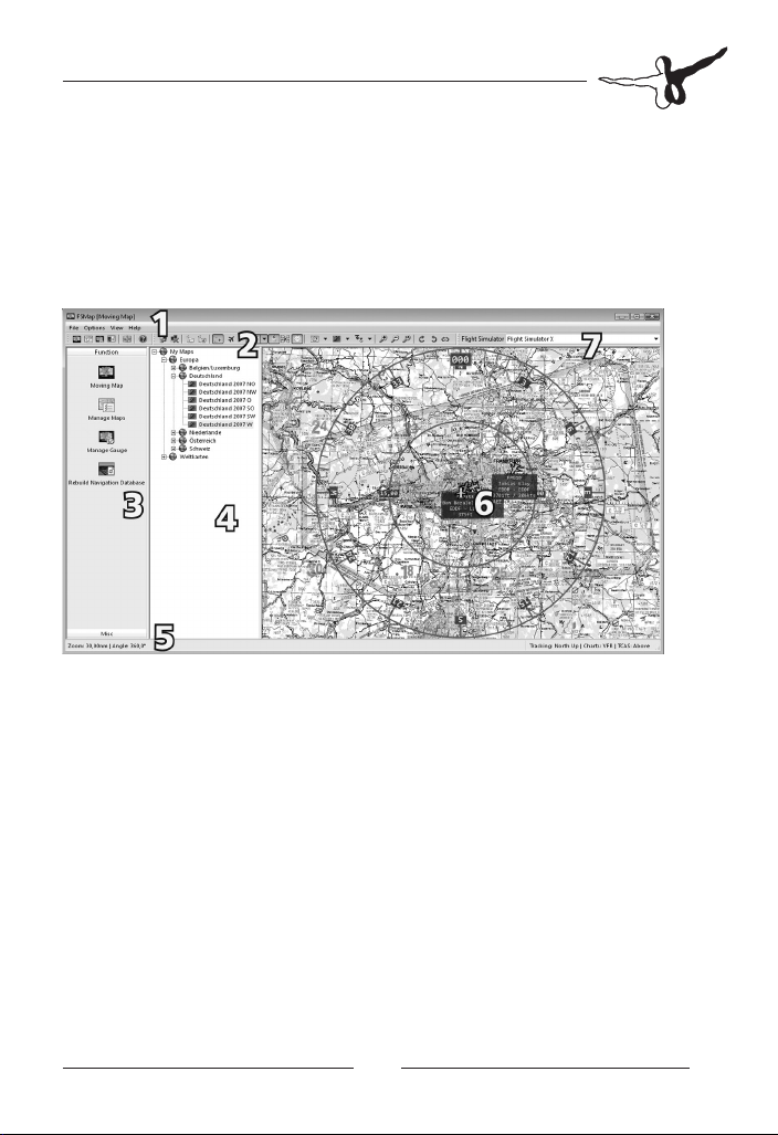
Menu bar1.
Icon bar 2.
Depending on which function is selected via the side bar, the
icon bar will look slightly different.
Side bar 3.
The side bar contains icons for the main functions of FSMap.
Currently, it is divided into 2 sections. Section „Function“
consists of FSMap´s core functions. „Misc“ has some links for
various support functions.
Entry bar 4.
The entry bar will contain menu trees for your installed charts,
or the aircraft and panels installed in your flight simulator.
What is displayed depends on the function chosen via the side
bar.
standard windows program
. It
Page 20

FSMap
Status bar 5.
The status bar will show current program parameters.
Display area 6.
The display area is the part of the program where the moving
map is displayed. In mode „Manage Maps“ it also shows the
currently active map. In mode „Manage Gauge“ you will see
the currently selected instrument panel.
Simulator selection 7.
This drop-down menu defines the currently selected flight
simulator version.
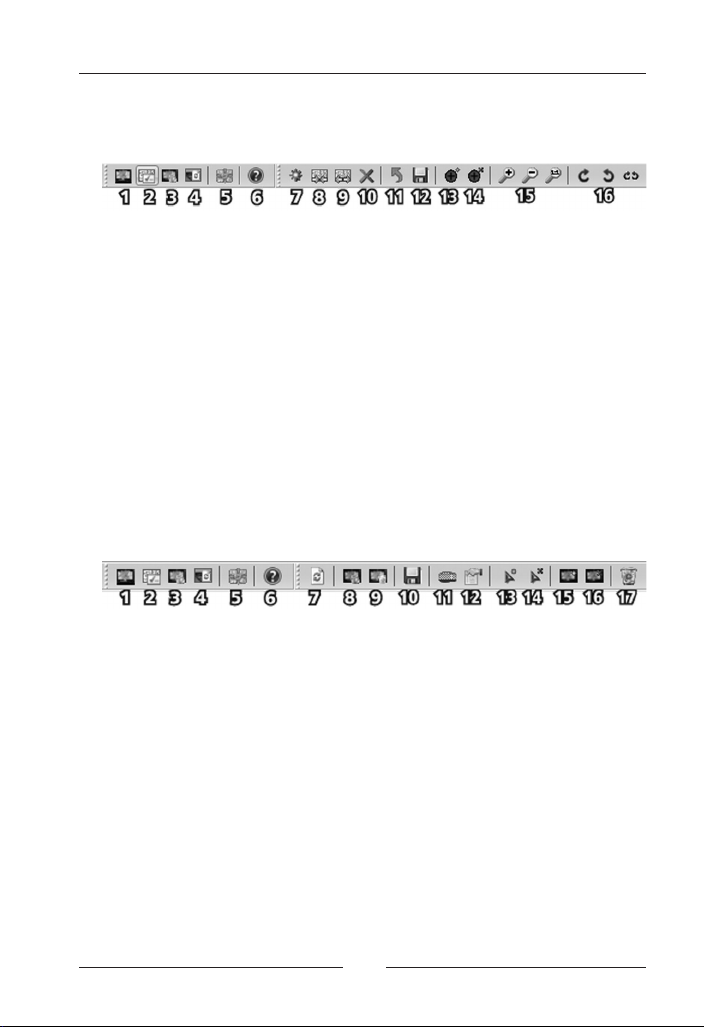
The Icon bars
Depending on which function is selected via the side bar, the icon bar
will look slightly different:
Function „Moving Map“ (F3)1.
Function „Manage Maps“ (F4)2.
Function „Manage Gauge“3.
Rebuild navigation database4.
Toggle full-screen display (F11)5.
Help (F1)6.
The icon bar „Moving Map“
Connect to Flight Simulator (F5)7.
Disconnect from Flight Simualtor (F6)8.
Load Flight Plan (CTRL-O)9.
Unload Flight Plan10.
Toggle Flight Plan display (CTRL-F)11.
Aerosoft GmbH 2008
20 21
Page 21

Toggle AI-Traffic display (CTRL-T) 12.
This icon contains a drop-down menu with the following
options:
•ShowGroundTrafc(CTRL-SHIFT+G)
•ShowAirborneTrafc(CTRL-SHIFT+A)
Toggle Online Traffic display (CTRL-SHIFT+V) 13.
This icon contains a drop-down menu with the following options:
•ShowGroundTrafc(CTRL-SHIFT+G)
•ShowAirborneTrafc(CTRL-SHIFT+A)
•ShowController(CTRL-SHIFT+C)
•ShowFIRBoundaries(CTRL-SHIFT+F)
•ShowactiveZones(CTRL-SHIFT+O)
Toggle Aircraft Label display (CTRL-L)14.
Toggle Aircraft Status display (CTRL-S)15.
Toggle Compass Rose display (CTRL-K)16.
Tracking Mode (SHIFT-F8 / F8)17.
Chart Type (SHIFT-F9 / F9) 18.
This icon contains a drop-down menu with the following options:
•All
•IFR
•VFR
TCAS Mode (SHIFT-F10 / F10) 19.
This icon contains a drop-down menu with the following options:
•Above
•Normal
•Below
•Unrestricted
•Off
Zoom in or out (Plus / Minus), or reset Zoom (CTRL-SHIFT+Z)20.
Rotate Right or Left (Right / Left), or Reset Rotation (CTRL-R)21.
Page 22
FSMap
The icon bar „Manage Maps“
7. Add Map (CTRL-N)
8. Import Map(s) (CTRL-I)
9. Export Regions/Maps (CTRL-E)
10. Delete Region/Map (DELETE)
11. Undo changes (CTRL-U)
12. Save changes (CTRL-S)
13. Add Calibration Point
14. Delete Calibration Point
15. Zoom in or out (Plus / Minus), or Reset Zoom (CTRL-SHIFT+Z)
16. Rotate Right or Left (Right / Left), or Reset Rotation (CTRL-R)
The icon bar „Manage Gauge“
7. Refresh Aircraft list (F5)
8. Install/Update FSMap Gauge
9. Uninstall FSMap Gauge
10. Save all Aircraft Modifications (CTRL-S)
11. Edit the Gauge Hotkey (CTRL-K)
12. Edit Properties (ENTER)
13. Adds a Hot to the selected Panel
14. Removes the selected Hot (DELETE)
16. Adds the FSMap to the selected panel
16. Removes the selected FSMap
17. Remove any FSMap and Hots installed on the selected panel
Aerosoft GmbH 2008
22 23
Page 23

FSMap Menu Structure
If you run FSMap the first time the registration window will appear.
Please enter your name, email adress and license key. You can find the
license key on the CD cover. Please keep this license key on safe place.
You will need it every time you want to reinstall FSMap.
The FSMap application has four major pull-down menus. The first one,
“File”, has entries to call the major functions of the program (“Moving
Map”, “Manage Maps”, “Manage Gauge” and “Rebuild Navigation
Database”). You may also define what language the application
should use here (English or German). Please note that the application
will restart when the language is changed. The entry “Recent Maps”
allows you to access maps you used be fore quickly. For this, key
combinations from ALT-1 to ALT-0 are also provided.
Page 24

FSMap
The menu “Option” is used to define basic parameters for the
application. There´s an entry for an option to create backup files, and
to check modified panels for the most obvious configuration errors.
The option “safe mode” should be used when the FSMap application
has crashed upon loading a panel. Some aircraft addons have been
developed for use inside Flight SImulator only, and may therefore act
strange when the panel is called outside the simulator. In this mode,
some panel graphics may not display correctly, therefore this mode
should be deactivated when editing the specific panel has been
completed. “Use alternate Map Drawing Method” forces the application
to use a map drawing method which is more memory-consuming, but
less CPU-intensive, at the expense of a reduction in display quality.
“Assigned CPU/Core” allows you to explicitly assign a CPU core to be
used by the program.
Other options will allow you to define the online network to be used
(VATSIM or IVAO), the maps display quality and the maps refresh rate.
These entries are self-explanatory.
The “View” menu configures the main program look. You may turn
the side bar, the entry list and the status bar on or off from here.
Aerosoft GmbH 2008
24 25
Page 25

The “Help” menu contains various entries which are in some way
related to the program support. The online help is accessible from here
(the whole manual is available in the online help system), and there are
links to the products’ home page and the support discussion forum.
“Contact Support” will call your eMail software and prepare an eMail
to the support team, where you can ask for further assistance. To report
a program bug, choose the “Bug Report” option, and provide the
necessary details via the dialog window (see screenshot on previous page).
Finally, “Registration” is where your program licence data has to be
entered. You may try out FSMap for a limited time by obtaining a trial
license. After you bought
the program, just copy the whole data (name, email and key), and
paste it anywhere inside the entry fields. The software will automatically
recognize the data, and fill out the form in the correct way. Alternatively
you may of course enter your registration data manually.
Page 26

FSMap
Quickstart guide
This quickstart guide should help you to get started with the program
instantly. Please note that this guide doesn’t replace a mandatory
reading of the full documentation.
Launch FSMap via the FSMap program icon in the Windows 1.
Start Menu.
Choose the correct Flight Simulator version from the drop-2.
down menu right to the icon bar.
Update the navigation database by clicking on the icon 3.
“ Rebuild Navigation Database” in the icon bar.
Add the FSMap gauge to a panel by using the Manage Gauge 4.
function. Add hots at your convenience to launch the gauge
from the panel. You may now close the FSMap application.
Start MS Flight Simulator, and select an aircraft to which FSMap 5.
was installed in step 3.
Start from an airport which is covered by the maps currently 6.
installed.
From your instrument panel, launch the FSMap gauge by either 7.
clicking on an installed hot, or by typing the FSMap hotkey.
After a few seconds, you will see the initialization screen.
Click on „FN“ until „MAP“ is displayed in the lower display 8.
area. Then click on the button below the map label. You will
now see a chart of your area. Your own position is represented
by an aircraft symbol, centred in the middle of the screen.
Aerosoft GmbH 2008
26 27
Page 27

Manage Maps
In order to use maps within FSMap, you first need to integrate and
calibrate them using the FSMap application. By calibrating the map
you are telling FSMap the geographical boundaries of your map. In
order to be calibrated correctly, at least two reference points need to
be defined using their exact geographical coordinates. To assist you in
this process, the Flight Simulator database of navigation aids may be
used as a reference.
FSMap accepts graphic files within the following limitations:
Size 8.000*8.000 pixel for the external FSMap application•
Size 5.000 x 5.000 pixel for the FSMap gauge•
Graphics formats JPG, PNG, TIFF, BMP or GIF•
All colour depths•
We highly recommend you to stay away from using the maximum
values. Smaller charts will be loaded and displayed much quicker. As
Flight Simulator (including all components) has to be run within a
single 2GB memory space, large charts may eat up and block huge
amounts of memory, and may slow down Flight Simulator significantly.
The following hints will help you to conserve memory:
Use maps with 8 bit colour depth instead of 32 bit files•
Use smaller chart files. A resolution of 2.500 x 2.500 pixel is •
sufficient in most cases.
You should seriously think about expanding your main memory to
2GB. The minimum necessary amount of main memory is 1GB.
Page 28

FSMap
Add new maps
Start the „Manage Maps“ function within the external FSMap 1.
application by clicking on the icon in the icon bar, or press F4.
Click on „Add Map“ in the icon bar, or press CTRL-N. You may 2.
also right-click at the position you want the map to be added
in the chart menu tree in the entry bar. Select „Add Map“
from the pop-up menu there. In this case the field „region“ is
already filled for you (see below).
Pick the map file from the selection window. The map will be 3.
displayed, and in the lower right area you will see a couple of
entry fields. Fill them as followed:
a. Name: You may freely choose a name for the map.
b. Region: This entry defines where inside the chart tree your
new chart will be placed. The backlash „\“ character will
be used as a hierarchy separator. As an example, „Europa\
Dänemark\VFR“ will create a new map entry with the
respective hierarchy levels (see screenshot on page 22):
c. Priority: The priority value will be defined automatically,
and does not need to be corrected manually. Priorities
Aerosoft GmbH 2008
28 29
Page 29

start with 0 at the lowest, and do not have an upper limit.
Automatic priority assignment take the geographical size
of the respective maps into account. Maps with smaller size
will receive higher priority values than maps with larger size
in the same area.
d. Altitude: There are two field which allow you to define
a lower and upper altitude limit for the map. Enter the
respective values here. As an example, this option may be
used to restrict the usage of a High-Level Enroute IFR chart
to the upper airspace above FL245 only.
e. Path: The full path to the map graphics. If you click on the
selection button to the right of the field, a selector window
will open which allows you to pick up the file.
f. Chart Type: You may choose between IFR, VFR, general
and airport charts. Airport charts are restricted to a small
area around an airport. General charts are always used. For
charts marked as IFR or VFR, the flight plan type from a
loaded flight defines which charts will be displayed.
Page 30

FSMap
g. Projection: You need to define which kind of map
projection your chart uses. Possible selections are „None“
or „Lambert Conical“. Usually, the projection used is stated
on the respective charts, mostly near the legend.
The next steps will differ slightly, depending on the projection method
used by the respective map:
For maps with projection type „None“:
Start with the calibration process by adding a calibration point. For
a successful calibration you will need at least two calibration points.
They should be located at map edges, as far away from each other as
possible. You need to know the exact geographical coordinates for
these points. We recommend you to use navigation aids like VORs,
NDBs or intersections. Those navigation aids are usually listed in the
national AIP (Aeronautical Information Publication), and often they are
also listed on the map itself.
To define a calibration point, right-click onto the map display where
you want the point to be placed, or select „Add Calibration Point“
from the popup-menu. A red crosshair will help you in correct placement.
By keeping the left mouse key pressed, the whole map may be moved.
Turning your mouse wheel will zoom the map in or out. For this the
cursor changes into a hand symbol. The currently selected calibration
point is displayed in green colour, other calibration points are marked red.
Aerosoft GmbH 2008
30 31
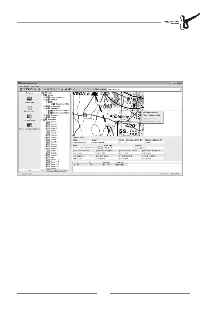
Page 31

The selected calibration point will now be added to a table of points,
just below the data entry area. You will see him with his relative position
(in pixels) inside your map. The fields for the geographical coordinates
are still empty. You may now enter these directly, or indicate the position
to be a navaid. In our case, our calibration point is located at the position
of the TNO (Trano) VOR in Denmark.
In case you don´t know the exact coordinates of your calibration point,
you may use the Flight Simulator navigation database as a reference.
If you enter the code for the navaid in either the latitude or longitude
field, FSMap will retrieve the correct coordinates, and use them. Please
note that these coordinates may differ from the exact position on the
chart, as the database may contain errors. In case you´ve selected a
code which exists in the database more than once, a selection dialog
will appear to allow you to select the right navigation aid.
As soon as a second calibration point is added, four more entry field
become active. They will define the borders of your map area. You
don’t need to fill the coordinates manually. Instead, two simple mouse
clicks will do the job. Zoom into the upper left corner, right-click
with your mouse, and select „Set Top/Left Corner“ from the popup
menu. In the same way, select the lower right border by choosing „Set
Bottom/Right Corner“ at the appropriate map position.
Page 32

FSMap
You may add more than two calibration points before defining the
map borders. However, 2-3 points should be sufficient to ensure a
precise map calibration.
To finish the map calibration process, click onto the disc symbol in the
icon bar, or press CTRL-S to save your changes.
For charts using the „Lambert Conical“ projection:
For charts using the „Lambert Conical“ projection method, a map
centre and two standard parallel longitudes must be indicated. These
standard parallel longitudes are usually depicted on a map right
together with the projection method itself (see sample scan below).
Unfortunately, the map centre coordinates are often missing. As a first
approach, select the middle of the whole map you are using as the
map centre, even if your file will only depict a fraction of the whole map.
Next, start adding calibrations points. For a successful calibration you
will need at least two calibration points. They should be located at
map edges, as far away from each other as possible. You need to
know the exact geographical coordinates for these points. We recommend
you to use navigation aids like VORs, NDBs or intersections. Those
navigation aids are usually listed in the national AIP (Aeronautical
Information Publication), and often they are also listed on the map itself.
To define a calibration point, right-click onto the map display where
you want the point to be placed, or select „Add Calibration Point“
from the popup-menu. A red crosshair will help you in correct placement.
By keeping the left mouse key pressed, the whole map may be moved.
Turing your mouse wheel will zoom the map in or out. For this the
cursor changes into a hand symbol. The currently selected calibration
point is displayed in green colour, other calibration points are marked red.
Aerosoft GmbH 2008
32 33
Page 33
The selected calibration point will now be added to a table of points,
just below the data entry area. You will see him with his relative position
(in pixels) inside your map. The fields for the geographical coordinates
are still empty. You may now enter these directly, or indicate the position
to be a navaid. In our case, our calibration point is located at the position
of the SS (Sturup) NDB in Sweden, near Malmoe.
In case you don’t know the exact coordinates of your calibration point,
you may use the Flight Simulator navigation database as a reference.
If you enter the code for the navaid in either the latitude or longitude
field, FSMap will retrieve the correct coordinates, and use them. Please
note that these coordinates may differ from the exact position on the
chart, as the database may contain errors. In case you’ve selected a
code which exists in the database more than once, a selection dialog
will appear to allow you to select the right navigation aid.
Now define the upper left and lower right corners. Zoom into the
upper left corner, right-click with your mouse, and select „Set Top/Left
Corner“ from the popup menu. In the same way, select the lower right
border by choosing „Set Bottom/Right Corner“ at the appropriate
map position.
Page 34

FSMap
The next screen shot above shows the navaid selection dialog mentioned:
To finish the map calibration you need to set at least 2 calibration
points, define the projection data (map centre, 2 parallel longitudes)
and identify the map edges. To save your map data, click on the disc
icon in the icon bar, or press CTRL-S to save.
Import Map
FSMap allows to import maps which are already calibrated. Those
maps may origin from other FSMap users, or from users of other „GIS
Software“. The frees you from having to do the calibration by yourself.
Supported file types are FS MovingMap INI-files, JGW-, TFW- or GFWfiles. We would like to take the opportunity to recommend a full set
of US sectional charts for VFR use, which have been precalibrated. You
may obtain them from the AVSIM file library. Check our links section at
the end of this manual for details.
To import a map, click on the corresponding icon in the icon bar, press
CTRL-I, or right-click at the appropriate place in the „My Maps“ tree. A
file selection dialog window will open, allowing you to select the correct
file to import. Please note that a small drop-down menu in the lower
right corner allows you to specify the exact file type you are looking for.
Aerosoft GmbH 2008
34 35
Page 35

When the file has been imported, you will be asked wether you want
to save the map in your personal map space. We recommend you
to confirm this. Your personal map space is a separate folder, which
will keep imported maps separated from those we deliver together
with FSMap. Your personal map space is located at C:\Documents
and Settings\<YOUR WINDOWS USERNAME>\My Files\FSMap\1.0\
Maps (Windows XP and Windows Vista). When the import process
is complete, you can change parameters like priority, chart name or
others.
FS Map allows you to export full map hierarchy tree branches. In such
cases the export will result in a couple of graphics files, and a single
calibration file. By importing such a calibration file you may import a
couple of files at once.
Charts need to be activated after they have been imported. To set
them active, place a checkmark in the chart tree just left of the new
chart entry. To finish the import process, and to save your changes,
click on the disc symbol in the icon bar, or press CTRL-S.
Export maps
You may export maps to make them available to other users. When
exporting maps, FSMap will always create at least two files: The graphics
file (the map itself), and a file with the calibration data. Those files are
exported using the .fsm file extension. To export maps, first select the
map from the „My Maps“ tree, then either click on the appropriate
icon in the icon bar, press CTRL-E, or right-click on the map entry you
want to export in the „My Maps“ hierarchy tree. By using the right-click
method you may export a full tree brach containing several individual
maps. A file save dialog window will open, prompting you for the
correct export location. Select the correct folder, and click on „Save“.
FSMap will now save the graphics and the .fsm file there.
FS Map allows you to export full map hierarchy tree branches. In such
cases the export will result in a couple of graphics files, and a single
calibration file. By importing such a calibration file you may import a
couple of files at once.
Page 36

FSMap
Manage Gauge
This function allows you to integrate the FSMap gauge into instrument
panels in MS Flight Simulator. The FSMap gauge may be used as part
of an existing panel view (i.e. filling a spot inside the panel), or it may
be opened as an independent panel window. Furthermore, you can
add a hotspot (a hidden click area to open the instrument) to your
panel windows.
When selecting the function „Manage Gauge“, FSMap will automatically
recognize all aircraft installed in the selected Flight Simulator version,
and arrange them in a sorted tree in the entry bar. The tree is sorted by
manufacturers, aircraft model, and variant. When you select a certain
variant, all panel views are listed below it with their respective names.
Clicking on a panel view will open the panel in the display area of the
FSMap application. The screenshot above shows the B737-400 main
panel view. Usually, all gauges used by the panel will also be shown.
Please note that there might be some panels where gauges may not
display correctly. This is due to some technical limitations, and gauge
manufacturers protecting their gauges. The panel window bitmap
itself however, should always be displayed, allowing you to add the
gauge and/or the hotspot without troubles.
Aerosoft GmbH 2008
36 37
Page 37

The FSMap gauge may be installed as an independent panel view (i.e.
as a panel window), or as a part of an existing panel window. Usually
you may want to use it as an independent panel window. In this case
you can open and hide it just as required. When opened, it may be
also moved around the screen, or resized. In this case, the panel window
may overlap some parts of the regular panel.
Some panels are offering specific spots to add instruments like a GPS
or a moving map device like FSMap. In such cases you may want
to place the FSMap gauge directly into that area. This is the most
realistic-looking variant. If the FSMap instrument is too small for your
taste, you may additionally create a separate FSMap panel window. In
these cases, the FSMap instrument which has been placed inside your
panel, acts like a hotspot. Clicking on it will open or close the larger
separate panel window.
All these installation or deinstallation actions related to the FSMap gauge
are done by clicking on the appropriate icon in the FSMap icon bar.
Adding or updating the FSMap
gauge file
Before adding the FSMap instrument to a panel you need to install
the FSMapDevice.gau file in MS Flight Simulator. To install the file, first
check that you have selected the correct flight simulator version via
the drop-down menu, then click on the icon labelled „Install/Update
FSMap Gauge“ in the icon bar. This symbol is greyed out when the
.gau file is already installed and up to date. The icon may become
active when the file is installed, but a newer version is available from
your program folder. Usually the FSMap application will detect such
cases and prompt you to update the FSMap gauge file to the latest
version.
Page 38

FSMap
Remove FSMap gauge from Flight
Simulator
To remove the FSMap gauge from Flight Simulator, click on the appropriate
icon in the icon bar. The FSMap application will ask you if you want to
remove all panel modifications from all aircraft as well. You may answer
“no” here to remove the gauge file only. Please note that some panels
may not work correctly after doing this. In this case you should remove
such panel modifications manually.
Add a hotspot to a panel
To add a hotspot for FSMap to a panel, first select the aircraft and
paintjob from the aircraft tree in the entry bar. Click on the panel view
where you want the hotspot to be added, and place the hotspot by
either clicking on the appropriate icon in the icon bar, or by selecting
“add hotspot” from the options menu accessible with a right-click.
Your new hotspot will appear in the upper left corner. The hotspot
has “grip handles” allowing you to resize and move the object with
your mouse as required. You may also use the keyboard instead of the
mouse: The hotspot can be moved using the arrow keys, SHIFT-arrows
will change the hotspot’s size. When keeping the CTRL-Key depressed,
all keyboard actions will happen accelerated. The currently selected
hotspot may be deleted by pressing the DELETE key. There is an appropriate icon in the icon bar available as well.
A hotspot doesn’t necessarily need to be visible. FSMap allows you to
place an invisible hotspot as well. To make a hotspot invisible, select
the hotspot, then right-click on it and choose “Edit Properties” from
the pop-up menu. A dialog window will appear. To turn the hotspot
invisible, sign the checkbox labled “Invisible hotspot”.
Aerosoft GmbH 2008
38 39
Page 39

Adding and removing the FSMap
instrument to/from a panel
To add a hotspot for FSMap to a panel, first select the aircraft and
paintjob from the aircraft tree in the entry bar. Click on the panel view
where you want the hotspot to be added, then click on the appropriate
icon in the icon bar. FSMap will ask you to if you want to install the
instrument in a separate panel window. If you choose “yes”, the
FSMap instrument will be added in a new panel window.
If you answer “No”, the FSMap instrument will be placed on the
panel view you selected earlier. Grip handles will appear on each side,
allowing you to resize the instrument, or move it around on the panel
window. Place the instrument at the appropriate place, and ensure
that no other gauges are covered.
You may also use the keyboard instead of the mouse: The hotspot can
be moved using the arrow keys, SHIFT-arrows will change the hotspot’s
size. When keeping the CTRL-Key depressed, all keyboard actions will
happen accelerated. The currently selected hotspot may be deleted by
pressing the DELETE key. There is an appropriate icon in the icon bar
available as well.
Page 40

FSMap
Define the FSMap instrument hotkey
FSMap allows you to assign a global hotkey for opening the FSMap
instrument in Flight Simulator. To define the hotkey, klick on the
appropriate icon in the icon bar, or press the CTRL-K key combination.
A dialog window will appear, asking you to enter the key combination.
If you keyed in the wrong combination, the backspace key will delete
your previous entry. Please note that any combination using the ALT
key will have the ALT key automatically converted into CTRL-SHIFT.
The FSMap hotkey definition is global, i.e. all instances in all panels are
sharing the same hotkey.
Aerosoft GmbH 2008
40 41
Page 41

Edit the FSMap instrument properties
When the FSMap instrument is selected in a panel window, you may
define some advanced parameters for the instrument. To do this, rightclick on the instrument, and select “Edit Properties” from the pop-up
menu. The parameters will be added to the FSMap gauge entries in
the relevant PANEL.CFG file.
The following parameters can be defined:
Window identifier: Assigns a numerical identification number to the
FSMap instrument. This number is assigned by the FSMap application
by default, and doesn’t need to be changed manually. The default
value is 14472.
Configuration name: Allows you to assign a specific name for this
instrument. All settings made in the FSMap instrument are saved to a
single configuration file. Setting an individual name here allows you to
save settings specifically for this particular instrument only.
Window position on startup: Defines where the instrument will
appear on the screen when called the first time.
Page 42

FSMap
Window with/height: The with and height of the FSMap instrument,
measured in pixels. Default values are 375 (with) and 281 (height). We
recommend you keep the aspect ratio to assure an optimum display
quality.
Panel light mode: Allows you to choose from two different methods
of instrument night lighting.
Visible on startup: Allows you to define wether or not the panel
window should be visible when loading the aircraft.
Aerosoft GmbH 2008
42 43
Page 43

The FSMap application
as a moving map
Connect FSMap to MS Flight Simulator
The FSMap application can be used as a moving map as soon as it
is connected to MS Flight Simulator. To establish a connection with
Flight Simulator 2004, the FSUIPC data interface is used (registered
FSUIPC versions only), while connections with FSX will be made using
Microsoft’s new interface called “SimConnect”. Please note that in
order to establish a connection from a networked PC via SimConnect,
the SimConnect client has to be installed first. For connections to
FS2004 via FSUIPC from a networked PC, the software “WideFS” is
needed, which needs to be purchased separately. For details about
installing SimConnect, please refer to the chapter “Installation” earlier
in this manual.
A connection to MS Flight Simulator will be established by clicking on
the correct icon in the icon bar, or by pressing the F5 key. The connection
should be terminated before closing MS Flight Simulator. Terminating
the connection is achieved by clicking on the appropriate icon in the
icon bar, or by pressing the F6 key.
As soon as the connection has been established, a map may be selected
from the map tree in the entry bar. The map will then be loaded and
displayed in the display area, centered on the middle of the map.
When a map has been loaded, it may be zoomed in or out using the
mouse wheel. You may also move the map around by moving the
mouse with the left mouse key pressed. Moving the mouse with the
left mouse key pressed, and additionally the SHIFT key pressed, will
rotate the map. Map navigation may be also done using the the
appropriate icons from the icon bar.
Page 44

FSMap
Loading a flight plan
A flight plan may be loaded and displayed on the map. Supported
flight plan formats include Microsoft’s own flight planner format
(FS2004/FSX) using files with the extension .PLN, flight plans created
by PMDG addons (PMDG B737NG and B747) using the extension.
RTE, and flight plans using the “PIC 767” format (compatible products
are B767 PIC and Level-D Sim B767), also using the .RTE extension.
To load a flight plan, click on the appropriate icon in the icon bar, or
press the CTRL-O key combination. After loading the flightplan, it will
be drawn on the map with a blue line. In case you´re not connected
to Flight Simulator, the most appropriate VFR chart is also loaded.
Waypoints along the route are displayed with an asterisk, and labeled
with their waypoint name.
Loading a flight plan in addition triggers the map usage filter. With
PMDG or PIC flight plans, the map filter will be set to “IFR”, causing
only maps marked as IFR maps to be used. When using an FS2004/
FSX flight plan, the flight mode selected when creating the flightplan
determines the map filter. Maps marked as “All” or airport maps are
always used. When no flight plan is used, the map filter will work
according to the selection in the map filter option in the icon bar.
Map display configuration
The map display may be adjusted to the users’ needs:
Full screen mode: You may toggle between the normal windows
map view, and a full-screen map view. To toggle, just right-click into
the display area. Another right-click will restore the windowed view.
Compass rose: A 360° compass rose may be displayed, which is
originally centered in the middle of the map. To display the compass
rose, click on the appropriate icon in the icon bar, or press CTRL-M.
The same action will hide the compass rose.
Aerosoft GmbH 2008
44 45
Page 45

Aircraft Status: Aircraft status data may be displayed in all four map
corners in semi-transparent overlay boxes. The upper left box will
show current wind speed and direction, the upper left box will display
temperature and dewpoint at the present location. The lower right
corner has info about the current elevation, the elevation above sea
level, and the current course (true and magnetic). Finally, the lower left
box shows the map zoom factor, your ground speed and the climb- or
sink rate (vertical speed in feet per minute).
The aircraft status display may be selected via the appropriate symbol
from the icon bar, or via the CTRL-S key combination. The symbol has
a drop-down menu with the following options in it:
Tracking Mode: This option determines how the map should act
when tracking the aircraft’s flight path. “Manual” means that the map
may be freely moved, resized and rotated. In “Track Up 360” tracking
mode, the map will always rotate to follow the aircraft’s current
track, i.e. the current track will always point upwards. In “Track Up
Arc” mode the map behaves in the same way, however, the aircraft
position will move from the map centre to the lower middle. When the
compass rose is displayed in “Track Up Arc” mode, it will be drawn as
a 120° arc only. The display mode resembles the ARC mode which is
popular with many EHSI displays (see screen below).
Page 46

FSMap
Finally, tracking mode “North Up” means that the map is fixed in a
north-up display position. The aircraft’s position displayed in the map
centre, and the aircraft symbol does change its orientation according
to the current aircraft’s track.
By clicking just on the “Tracking Mode” icon in the icon bar, you will
be cycling through the different tracking modes. A message reporting
the current mode will appear in the middle of the map display.
AI-Traffic: Your map display can be configured to show the AI traffic
which is currently active. To activate AI-Traffic display, click on the
appropriate icon in the icon bar, or press CTRL-T. A drop-down menu
integrated into the icon will allow you to choose, which traffic will be
displayed exactly. You may separately toggle traffic on the ground or in
the air, and cycling through the options by clicking on the icon.
Aircraft on the ground will be displayed using a grey symbol, traffic
in the air is depicted with a green symbol. Above the symbol you will
see the aircraft’s current altitude in reference to your own altitude. The
aircraft label displayed below the symbol contains the radio callsign,
departure- and destination airport, altitude and airspeed. The label
may be toggled separately using the appropriate icon from the icon
bar, or by pressing CTRL-L. The following screenshot shows FSMap
with AI traffic enabled. Additionally, the compass rose and the aircraft
status displays were enabled. Also, a flightplan from Frankfurt to
Aerosoft GmbH 2008
46 47
Page 47

Bruxelles was loaded and shown.
Online-Traffic: By clicking on the appropriate icon in the icon bar, you
may activate the display of traffic from the online networks VATSIM
or IVAO. The network used depends on your selection made via the
“options” pull down menu. Alternatively, the key combination CTRlSHIFT-V may be used to display online traffic. Online traffic will be
displayed in the same way like AI-Traffic. In addition, the drop-down
menu from the icon bar contains options to display online ATC presence,
active control zones, and FIR borders. All active ATC positions will be
depicted with a grey tower symbol. To better represent ATC staffing,
active center controllers will have their FIR area or control sector
shaded grey. Approach and tower controllers are represented with
coloured circles around their position. Tower controllers are identifiable
by yellow ones, approach controllers by green circles.
Page 48

FSMap
The following sample screenshot shows traffic from the IVAO network:
When online traffic is displayed, the aircraft label looks slightly different.
It will now show the callsign, the name of the participant and his
home airport, instead of the radio callsign seen with AI-Traffic.
TCAS-System: FSMap comes with a completely integrated TCAS
( Traffic Collision and Avoidance System), which will warn the user of
close encounters in the air (AI-Traffic only). The TCAS system can be
configured by using the icon and the integrated drop-down menu in
the icon bar, or by using the F10/SHIFT-F10 key combinations. By toggling
the options the systems cycled through modes “Above”, “Normal”,
“Below”, “Unrestricted” or “Off”. With these modes activated, traffic
display will be restricted as followed:
Above: 9000ft above / 2700ft below•
Normal: 2700ft above / 2700ft below•
Below: 2700ft above / 9000ft below•
Unrestricted: No altitude restrictions apply•
Off: No TCAS warnings are generated, all traffic is displayed•
When other traffic closes in below 6nm horizontally and +/- 1200ft, the
aircraft symbol starts flashing. This is called a TCAS warning. Should other
traffic come close below 25 seconds to a potential collision, and below
+/- 700ft in altitude, an audible alert will also be played (TCAS alert). The
warnings will end when the other traffic gets out of the respective ranges.
Aerosoft GmbH 2008
48 49
Page 49

The FSMap
Instrument/Gauge
This chapter describes the functionality of the FSMap instrument. The
FSMap instrument is working in English language only. The following
screen shot illustrates its main controls:
FN key: 1. Toggles the main menu levels, or returns to it from a
sub-menu.
Smart (Function) Keys (SFK): 2. Will access the blue menu
selections, or the green menu options.
Rotary knob and push button: 3. The rotary knob complements
the action of the SFKs in some menus where arrows will appear
indicating the direction to turn the knob. A round push button
symbol “o” in a menu option indicates that pressing the knob
will have the same effect. Pressing the knob is achieved by
right-click with the mouse on it.
Page 50

FSMap
Menu/ENT Key: 4. Pressing the Menu/ENT key will show a menu
of options to modify the display of the current function. Pressing
the Menu/ENT key again will hide the menu. If no action is
taken, the menu will automatically extinguish in 20 seconds.
Menu Item Keys (MIKs): 5. When a menu is activated by the
Menu/ENT key, the MIKs will scroll through all choices when
pressed. Some options support multiple choices, such as in
Map mode.
Power Rocker Switch: 6. The power rocker switch turns the
instrument on or off, and controls the display brightness. Pressing
the “+” switch with a left click turns it on, further presses on
“+” or “-” will control the brightness. Right-clicking on either
“+” or “-” will switch the instrument off. Please note that the
gauge may not be switched off from the startup screen. Select
any other screen first before turning off the instrument.
When installed in a separate panel window, the instrument can be
displayed by either clicking on any installed hotspot, by pressing a
defined hotkey, or by selecting the instrument from the “Views” menu
in Flight Simulator. In case you´ve integrated the instrument into an
existing panel view, you may operate it directly there. In this case the
instrument may be zoomed by clicking into its display area. Klicking
into the upper right corner of the zoomed FSMap window will alwas
close the FSMap panel window.
Aerosoft GmbH 2008
50 51
Page 51

The FSMap instrument menu system
When pressing the FN function key, a list of main functions, such als
“MAP”, “TRAF”, “MSG” etc. is displayed. Each time you press the FN
key you will step through the list of menu items. After you press one
of the function “smart” keys (SFKs) at the bottom of the display, the
function keys change to provide options to control the display related
to the current menu option, now in green. Change the function keys
back to the menu list by pressing the FN key.
Menu list 1
MSG: Displays the message log. An amber MSG flag will flash until
the message is reviewed. The MSG flag will remain in view as long as
the message log contains messages. New messages will be highlighted
in boldface. Use the “UP/DOWN” SFKs to move to additional messages,
if more than one page of messages exist. Press “Clear” to remove the
stored messages.
MAP: Displays the moving map. The SFK keys will present the functions
“In” and “Out” to zoom the map display, “Pan” to pan around the
map, and “Info” to display information about nearby airports and
navaids. The pan mode will be covered later in the chapter in greater
detail.
IFR: Will load the IFR map with the highest priority related to the
current aircraft position.
VFR: Will load the VFR map with the highest priority related to the
current aircraft position.
Page 52

FSMap
Menu list 2
TRAF: Activates the traffic display mode. Your own aircraft position
will appear in the middle of the screen, represented by a small
triangle. Two range rings will represent the current display range, and
the halfway distance. The display range may be adjusted using the
“In” and “Out” SFKs, or by turning the rotary knob. You may also
adjust the range by using the mouse wheel when the mouse cursor is
overhead the rotary knob or the appropriate SFKs. The SFK “Vert” will
cycle through the different vertical TCAS display modes:
Above: 9000ft above / 2700ft below•
Normal: 2700ft above / 2700ft below•
Below: 2700ft above / 9000ft below•
Unrestricted: No altitude restrictions apply•
The selected vertical mode is indicated in the lower right corner of the
display.
PLN: Displays the flight plan information page. The middle upper area
will display the next active waypoint. The main area is divided into a
left and right area. On the left side, all waypoints in your current flight
plan are listed. On the right side, details about the currently active
waypoint are shown. The SFKs 1 and 2 will step through the individual
waypoints. When the selected waypoint is a navaid, further information
about it is displayed on the right half of the screen. When selecting an
airport, several pages of information are available, including frequency,
runway information, and a graphic showing the airport layout.
Flight plans need to be loaded via the Flight Simulator’s Flight Planner
feature.
SYS: Displays the FSMap system configuration menu.
The system configuration menu contains core settings for the FSMap
instrument. All settings are saved to a single configuration file. In case
you assigned a configuration name to the FSMap instrument (check
page 37 for details), your settings apply to this specific instrument only.
The system configuration menu offers the following options:
Aerosoft GmbH 2008
52 53
Page 53

Menu level „Nav“
Distance Units: Nautical miles (nm) or kilometer (km)
Altitude Units: Feet (Feet/ft) or meter
Speed Units: Knots (kt), kilometers per hour (km/h) or miles per hour
Baro Units: Millibar (european) or In.Hg. (american)
Temperature Units: Celsius or Fahrenheit
TCAS Altitude (ft): The trigger altitude for TCAS warnings. Choose
from 500ft to 2500ft. Default value is 1200ft.
TCAS Range (nm): The trigger range for TCAS warnings. Choose
from 5.0nm to 12nm. Default value is 6.0nm.
Ground Traffic Altitude (ft): The trigger altitude to display ground
traffic. Choose from 0ft - 5000ft. Default value is 1000ft.
Ground Traffic Range (nm): The trigger range to display ground
traffic. Choose from 0nm - 14nm. Default value is 10nm.
Aircraft Symbol: Defines the symbol for your own aircraft in map
mode. You may choose between “Jet” and “Prop” aircraft with one or
two engines.
Initial Enroute Zoom (nm): The initial map zoom when the map
display changes from ground to enroute charts.
Initial Ground Zoom (nm): The initial map zoom factor after gauge
startup, when the aircraft is on the ground.
Transition Speed (kts): The speed where the FMap instrument switches from ground charts to enroute charts. The value should ideally
match your takeoff speed.
SmartZoom Minimum Scale (nm): Smallest zoom factor for which
the SmartZoom function is working. Choose from 0.2nm to 1500nm,
with the maximum being the value for „SmartZoom Maximum Scale“
(see below).
Page 54

FSMap
SmartZoom Maximum Scale (nm): Largest zoom factor for which
the SmartZoom function is working. Choose from 0.1nm to 500nm,
with the minimum being the value for „SmartZoom Minimum Scale“
(see above).
Menu level „Perf“
Quality Mode: Defines the display quality for the digitized charts.
Valid options are “Performance”, “Quality” and “High Quality”.
Transparent information boxes are available in “High Quality” mode
only. Please note that high quality levels may degenerate system
performance.
Assigned CPU/Core: Allows you to assign the operation of the
FSMap instrument specifically to a certain core in a multi-core system.
We recommend you to assign core 2 in a dual-core system to FSMap.
In a quad-core system, choose core 3 or 4. You should try this option
even if your PC has a hyperthreading CPU (Pentium 4) only.
Refresh Rate: Defines the screen refresh rate in steps of 56ms each.
Traffic Refresh Rate: Defines the refresh rate for traffic data in steps
of 56ms each.
Menu level „Test“
Allows you to choose from a set of coloured test screens to test the
quality of the FSMap display.
Aerosoft GmbH 2008
54 55
Page 55

The FSMap instrument as a moving map
The moving map mode is activated by pressing the SFK assigned to the
“Map” function. To specifically load the most appropriate IFR of VFR
map, press the accompanying SFKs from the menu level.
The screenshot above shows the FSMap instrument in Map Mode.
A flightplan from Frankfurt (EDDF) to Bruxelles (EBBR) is loaded and
displayed. In addition, traffic is displayed, and the map options menu
is opened. After the map is loaded, you may zoom in and out using
the SFKs labeled “In” and “Out”. Note that these options feature an
arrow sign, indicating that this option may be also invoked with the
rotary knob. SFKs features the pan option (also available by pushing
the rotary knob), which will cause 4 arrows to appear on the right
hand side of the displays. In pan mode, the map my be moved below
your aircraft symbol in 4 directions, indicated by the arrows. A green
line will be drawn from the current map center back to the own
aircraft’s position. Zooming is also available while in pan mode. Pan
mode is cancelled by pressing the FN key once.
Page 56

FSMap
Options Menu page 1
Flightplan: The currently loaded flightplan will be drawn on the map.
Tracking Mode: In “Track Up 360” tracking mode, the map will
always rotate to follow the aircraft’s current track, i.e. the current track
will always point upwards. In “Track Up Arc” mode the map behaves
in the same way, however, the aircraft position will move from the
map centre to the lower middle. When the compass rose is displayed
in “Track Up Arc” mode, it will be drawn as a 120° arc only. The
display mode resembles the ARC mode which is popular with many
EHSI displays. Finally, tracking mode “North Up” means that the map
is fixed in a north-up display position. The aircraft’s position displayed
in the map centre, and the aircraft symbol does change it´s orientation
according to the current aircraft’s track.
Nav-Data: This option corresponds with the setting “Aircraft Status”
in the external FSMap application. You may cycle through “No Data,
“Nav Data”, “Full Nav Data” and Weather Data”. When “No Data”
is selected, the screen is clear of any information. “Nav Data” shows
the next waypoint in the upper left, the course to that waypoint in
the upper right, the distance in the lower right, and the map zoom
factor in the lower left corner. In “Full Nav Data” mode, the displays
are amended to read out the current ground speed (lower right), and
altitude and barometric pressure (lower left). When working with the
“Weather data” mode, the upper left display box has the wind speed
and -direction instead of the next waypoint. The upper left info box
displays the current temperature as TAT and OAT.
Traffic: Activates or deactivates AT-Traffic overlay display. The amount
of AI traffic being displayed depends on the chosen TCAS mode (see
TCAS configuration earlier in this chapter). Please keep in mind that
displaying AI traffic may significantly slow down the performance of
the FSMap instrument in Flight Simulator.
Compass Rose: Activates or deactivates the display of the compass
rose in either full (360°) or Arc (120°) mode.
Aerosoft GmbH 2008
56 57
Page 57

TCAS: Configures the vertical TCAS mode. The modes are defined as
followed:
Above: 9000ft above / 2700ft below•
Normal: 2700ft above / 2700ft below•
Below: 2700ft above / 9000ft below•
Unrestricted: No altitude restrictions apply•
TCAS Audio: Toggles audible TCAS alerts
Label: Toggles the display of waypoint names in map mode, when a
flight plan is loaded and displayed.
APT Details: When zooming into a high zoom level, the map reverts
to display a detailed airport map with runways, taxiways and parking
positions. Taxiways are labeled with their correct identifiers.
Smart Zoom: When “Smart Zoom” is activated, the FSMap instrument
will automatically adjust the maps zoom factor to keep the next
waypoint in the flight plan in view. The minimum zoom factor is 2nm.
“Smart Zoom” is indicated by an “A” letter to the left to the zoom
factor display in map mode.
Page 58

FSMap
The FSMap instrument as a TCAS
display
Your own aircraft position will appear in the middle of the screen,
represented by a small triangle. Two range rings will represent the
current display range, and the halfway distance. The display range may
be adjusted using the “In” and “Out” SFKs, or by turning the rotary
knob. You may also adjust the range by using the mouse wheel when
the mouse cursor is overhead the rotary knob or the appropriate SFKs.
The SFK “Vert” will cycle through the different vertical TCAS display
modes:
Above: 9000ft above / 2700ft below•
Normal: 2700ft above / 2700ft below•
Below: 2700ft above / 9000ft below•
Unrestricted: No altitude restrictions apply•
The selected vertical mode is indicated in the lower right corner of the
display. Please note that the vertical mode may also be defined via the
TCAS display option menu (see below).
Aerosoft GmbH 2008
58 59
Page 59

For the TCAS display, the Menu/ENT opens an own configuration
menu with the following options:
Alert: Allows you to choose how the system should inform about
traffic warning and alerts. When “None” is selected, traffic warnings
are listed in the message window only. In “Prompt” mode the system
will reconfigure the system menu bar at the bottom of the screen,
allowing you to access the traffic mode with one button/click only. In
“Pop-Up” mode a small TCAS display will appear as an overlay in the
upper left corner of the screen. “Pop-Up” or “Prompt” will not work
in Map Mode when traffic display is activated.
Switches between altitude readouts relative to own altitude, or
Alt:
absolute data.
TCAS: Configures the vertical TCAS mode. The modes are defined as
follows:
Above: 9000ft above / 2700ft below•
Normal: 2700ft above / 2700ft below•
Below: 2700ft above / 9000ft below•
Unrestricted: No altitude restrictions apply •
This function is identical with the “VERT” option available on the traffic
display via a smart function key (SFK).
Standby-Mode: Toggles the TCAS standby mode. In Standby mode
no warnings or alerts are issued. The display works as a traffic radar only.
Audio: Activates or deactivated audible traffic warnings and alerts.
When other traffic closes in below 6nm horizontally and +/- 1200ft, a
warning is issued, and the aircraft symbol changes to a turquoise-filled
rhombus. This is called a TCAS warning. Should other traffic come
close below 25 seconds to a potential collision, and below +/- 700ft in
altitude, an audible alert will also be played (TCAS alert). The warnings
will end when the other traffic gets out of the respective ranges.
Please note that the trigger values for the TCAS warning may be adjusted
via the system configuration menu.
Page 60

FSMap
The screenshot on the next page shows the instrument in TCAS mode,
with the options menu activated. Please note the TCAS warning
generated by the aircraft 1800ft above and 100ft below the own
position in the middle of the screen. The aircraft’s rhombus is filled,
and a white box in the upper left corner displays “Traffic alert”,
indicating that this is a traffic warning:
The next screen shows the TCAS system in TCAS Alert state: The intruder
aircraft symbol has changed into an amber point, and the “Traffic
Alert” (now coloured yellow) flag will flash for 10 seconds.
Aerosoft GmbH 2008
60 61
Page 61

The picture below displays the FSMap instrument in Map Mode, with
a traffic alert displayed in Pop-Up mode. Note the overlayed TCAS
display in the upper left corner, with the yellow flashing “Traffic Alert”
flag just below:
Please note that the “Pop-Up” and “Prompt” alert modes will be active
only when the traffic display in the map options menu is turned off.
Page 62

FSMap
Credits
Concept, Development and Programming
Thomas Molitor
Documentation
Martin Georg and Thomas Molitor
Additional Control Programming
Dirk Bunar (Tribe Technology)
ICAO VFR Maps
Deutsche Flugsicherung GmbH (DFS)
Skyguide und swisstopo
Global Maps
NASA‘s Earth Observatory
Special Thanks to
my wife Katja, my daugther Emily, and my cats Noel and •
Sylvester for their endless patience during the development
time. MANY THANKS!!!
Dirk Bunar and Axel Reddehase (Tribe Technologies)•
Mathijs Kok and Winfried Diekmann for their business support•
The whole Beta Test Team !!!•
Aerosoft for their interest in this product•
and the Flight Simulator community for many creative ideas, and their
marvelous support.
Aerosoft GmbH 2008
62 63
Page 63

Chart resources
VFR charts for USA (precalibrated):
http://www.avsim.com
A free-of-charge registration for the “File Library” is necessary. When
searching for files, use the “extended search” option and enter “Matt
Fox” for the author, and “Sectional Chart” for the description.
Terminal- and Enroute-Chart for Europe (IFR):
http://ead.eurocontrol.int
Free-of-charge registration is required. We recommend to choose the
simple HTML menu option. Charts are available from the “PAMS light
(AIP) submenu.
Many countries in Europe do charge users for accessing aeronautical
charts. Please visit the respective website of the national authorities
for details. In some cases listed below, you may get charts from these
pages for free. Please consult the individual website documentation
about how to access charts.
Charts for Bosnia-Herzegowina:
http://www.bhdca.gov.ba/ais.htm
Charts are accessible via 4 grey-marked weblinks in the upper area of
the page.
VFR-Charts for Denmark:
http://www.slv.dk/Dokumenter/dscgi/ds.py/View/Collection-29
Charts for Norway:
http://www.ippc.no/norway_aip/current/main.html
Charts for Finland:
https://ais.fi/ais/eaip/en/index.htm
Page 64

FSMap
Charts for France:
http://www.sia.aviation-civile.gouv.fr/html/frameset_aip_uk.htm
Charts for the Czech Republic:
http://lis.rlp.cz/ais_data/www_main_control/frm_en_aip.htm
Charts for Slowenia:
http://www.sloveniacontrol.si/acrobat/aip/eaip/Operations/history-en-
GB.html
Charts for the United Kingdom:
http://www.ais.org.uk/aes/login.jsp
(Free-of-charts registration necessary)
Charts for Australia:
http://www.airservicesaustralia.com/publications/aip.asp
Charts for New Zealand:
http://aip.net.nz/
Charts for Nort-West Africa:
http://www.ais-asecna.org/en/index.htm
Aerosoft GmbH 2008
64 65
Page 65

Map legend ICAO-Charts
Page 66

FSMap
Aerosoft GmbH 2008
66 67
Page 67

Page 68

FSMap
Aerosoft GmbH 2008
68 69
Page 69

FSMap Keyboard Reference
General functions
F1 Online Help
CTRL-F1 Help Index
CTRL-ALT-F1 Help Search
F3 Moving Map
F4 Manage Maps
F11 Toggle Full-Screen Display
ALT-1 - ALT-0 Open recent Maps
Funktion Area „Moving Map“
F5 Connect to Flight Simulator
F6 Disconnect from Flight Simulator
F8/SHIFT-F8 Tracking Mode
F9/SHIFT-F9 Chart Type
F10/SHIFT-F10 TCAS Mode
CTRL-O Load Flight Plan
CTRL-F Toggle Flight Plan display
CTRL-T Toggle AI-Traffic display
CTRL-SHIFT-V Toggle Online Traffic display
CTRL-L Toggle Aircraft Label display
CTRL-S Toggle Aircraft Status display
CTRL-M Toggle Compass Rose display
Plus Zoom In
Minus Zoom Out
CTRL-SHIFT-Z Zoom Reset
Page 70

FSMap
Right Rotate Right
Left Rotate Left
CTRL-R Reset Rotation
Funktion Area „Manage Maps“
CTRL-N Add Map
CTRL-I Import Map(s)
CTRL-E Export Region(s)/Map(s)
ENTF Delete Region/Map
CTRL-U Undo changes
CTRL-S Save changes
Plus Zoom In
Minus Zoom Out
CTRL-SHIFT-Z Zoom Reset
Right Rotate Right
Left Rotate Left
CTRL-R Reset Rotation
Funktion Area „Manage Gauge“
F5 Refresh Aircraft list
CTRL-S Save all Aircraft Modifications
CTRL-K Edit the Gauge Hotkey
EINGABE Edit Properties
ENTF Remove the selected Hotspot
ENTF Remove the selected FSMap Instrument
Aerosoft GmbH 2008
70 71
Page 71

Page 72

Add-ons
for Microsoft FSX
www.aerosoft.com
Aerosoft GmbH • Germany
E-Mail: info@aerosoft.de
PMDG 747-400 X
€ 59.99
Piper PA-31T Cheyenne X
€ 39.99
Piper PA-31T Cheyenne X
Four versions of the classic Turboprop!
Jump into the excellent Piper Cheyenne, now with a
fully functional weather radar for FSX. The models have
been reworked from scratch and have been equipped
to suit all FSX features. This includes texturing, 3D
model materials and camera positions. Choose between
pilot or co-pilot seat or even take a seat in the cabin. All
variants of this model have been rebuilt to suit the real
life aircraft.
PMDG 747-400 X
Queen of the Skies!
The PMDG 747-400 is the answer for Jumbo-Jet enthusiasts who demand exceptional functionality and visual
appeal! Stunning photorealistic cockpit and exterior
models combined with an accurate systems functionality.
The completely new models of the PMDG 747-400
Queen of the Skies have been exclusively designed for
FSX implementing new features such as specular
lighting and bump-mapping.
 Loading...