

Page 1
Add-on for Microsoft
Flight Simulator
and FS2004!
9
Manual
Page 2

FlightSim Commander 9
Developed by: Sascha Felix und Volker Heine
Manual: Sascha Felix, Volker Heine, Günter Zehnel
Installation: Andreas Mügge
Copyright: © 2010 / Aerosoft GmbH
Flughafen Paderborn/Lippstadt
D-33142 Büren, Germany
Tel: +49 (0) 29 55 / 76 03-10
Fax: +49 (0) 29 55 / 76 03-33
E-Mail: info@aerosoft.de
Internet: www.aerosoft.de
www.aerosoft.com
Aerosoft GmbH 2010
2 3
Page 3
FlightSim
Commander 9
Manual
Add-on for
Microsoft Flight Simulator X
and Flight Simulator 2004
Page 4

FlightSim Commander 9
Content
Introduction ...............................................................8
Hardware and software requirements .................................. 10
Installation ............................................................................... 11
Getting started ........................................................12
Database Manager .................................................................. 13
Updating airport files ............................................................ 15
Map Window ............................................................21
Navigating around the map ................................................... 23
Mouse position ..................................................................... 23
Moving around the map ....................................................... 23
Compass .............................................................................. 23
Rubber band selection .......................................................... 24
Information label .................................................................. 24
Aircraft (always) on Map ....................................................... 25
Always on Top ...................................................................... 26
Zoom ................................................................................... 26
Buttons ..................................................................................... 28
Display buttons ..................................................................... 28
Function buttons .................................................................. 29
Intersections and airspaces..................................................... 30
Intersections and fixes .......................................................... 30
Airspaces .............................................................................. 30
AI traffic and TCAS .................................................................. 31
Tools ......................................................................................... 32
Select parking & taxiways ..................................................... 32
Runway approach path ........................................................ 33
Measuring distance and course ............................................. 34
Finding a map object ............................................................ 34
Transferring frequencies to Flight Simulator .......................... 35
Airport Information ................................................................ 36
Aerosoft GmbH 2010
4 5
Page 5

Flight planning ......................................................... 37
Basic techniques ...................................................................... 38
A simple flight plan: selecting
departure and arrival airports ................................................ 38
Adding waypoints to a flight plan ......................................... 40
Selecting waypoints manually ............................................... 42
AFIL (air filed) and ZZZZ flight plans ...................................... 44
SIDs, STARs and transitions .................................................... 47
Inserting SIDs, STARs, and transitions .................................... 47
A further comment on SIDs and STARs ................................. 50
Custom waypoints .................................................................. 51
Selecting custom waypoints .................................................. 51
Custom waypoints with precise location ............................... 52
Editing the flight plan table ................................................... 55
Deleting an old flight plan and creating a new one ............... 57
Printing flight plans .............................................................. 57
Advanced techniques .............................................................. 58
A sample flight plan from EDDH to ESSA .............................. 58
A mixed airway and VOR-to-VOR flight plan ......................... 60
A word of caution ................................................................ 61
Alternate airports .................................................................... 62
Creating a flight plan from an airway route ......................... 63
A closer look at the flight plan table ..................................... 65
Saving and loading flight plans ............................................. 69
Route segments ....................................................................... 71
User Waypoints ....................................................................... 74
Adding user waypoints ......................................................... 75
Deleting user waypoints ....................................................... 76
Editing user waypoints .......................................................... 76
User objects..............................................................77
Logbook .................................................................... 78
Aircraft Window .......................................................79
Editing aircraft parameters ..................................................... 79
Adding new aircraft ................................................................ 80
Page 6

FlightSim Commander 9
Deleting existing aircraft ........................................................ 80
Aircraft parameters ................................................................. 80
Fuel Window ............................................................. 81
Approach Window ...................................................82
GPS and moving map ..............................................84
GPS Window ............................................................................ 84
The General Page ................................................................. 85
The Waypoint Page ............................................................... 85
Weather Page ....................................................................... 86
The Arrival Page .............................................88
The ILS Page ......................................................................... 89
The Runway Page ................................................................. 89
Switching waypoints manually ..................... 90
Operating modes .................................................................... 91
AutoHeading mode .............................................................. 91
GoTo mode .......................................................................... 91
Transmitting frequencies to Flight Simulator .......................... 91
Moving Map ............................................................................ 91
Distance arc .......................................................................... 92
Great Circle navigation ...........................................94
Holding Window ......................................................95
Blackbox and flight analysis ...................................98
Track and altitude .................................................................... 98
Flight recording and analysis ................................................. 99
Saving flight recordings for GoogleEarth© ......................... 100
VFR flights ..............................................................102
Checking control zones ......................................................... 102
Violating control zones ......................................................... 103
Sunrise and sunset ................................................................ 104
Aerosoft GmbH 2010
6 7
Page 7

NATracks and PACOTs ............................................105
Weather ..................................................................108
IVAO and VATSIM flights .......................................109
Fellow pilots‘ aircraft ............................................................ 112
A note on VATSIM and IVAO airspaces ................................ 112
Information on pilots and controllers .................................. 114
Connecting to the IVAO Teamspeak Server ......................... 117
Online friends ........................................................................ 118
Options Window ....................................................119
Colors ..................................................................................... 119
Color Themes ..................................................................... 120
Display ................................................................................... 121
Flight ...................................................................................... 122
Flight Plan .............................................................................. 124
Online ..................................................................................... 126
Hotkeys .................................................................................. 127
Downloads ............................................................................. 128
Appendix ................................................................129
Loading databases for FS2004 or FSX .................................. 129
Directly connecting to Flight Simulator ............................... 130
Multiplayer mode and online flights ................................... 131
Appendix Network ................................................132
Establishing a network connection with Peter Dowson’s
WideFS (WideServer+WideClient) ........................................ 132
Step 1: Setting up the server ............................................... 133
Step 2: Setting up the client ............................................... 136
Checking the result in FlightSim Commander...................... 138
Non-standard locations of scenery files .............................. 139
Page 8

FlightSim Commander 9
Introduction
Welcome to FlightSim Commander 9, a flight planner, navigator, and
scenery viewer for both Microsoft Flight Simulator 2004 and Flight
Simulator X.
FlightSim Commander allows you to:
create flight plans automatically, manually, or both for any section of
your route
• create flight plans along low altitude and high altitude airways
• create a database of your own custom waypoints
• insert Standard Instrument Departures (SIDs) and Standard
Arrival Routes (STARs), and transitions
• create and reload route segments for departure, arrival, and
enroute
• display, update and choose for flight planning North Atlantic
Tracks (NATracks) as well as Pacific Organized Tracks (PACOTs)
• look at airport layouts including runways, taxiways, and aprons
• show a Jeppesen-style vertical and horizontal approach chart
for runways of your destination airport
• display available missed approaches at your destination airport
• calculate fuel consumption and alternate airport
• look at a map displaying VORs, NDBs, ILS‘es, airports, runways,
MSA (minimum safe altitude), 12 types of airspaces as well as
coastlines and national boundaries
• use a GPS display for easy navigation
• automatically transmit ILS frequencies to Flight Simulator
• set an autopilot for following the filed route or to go directly to
a chosen geographic location
• choose fly-by or fly-over for passing waypoints
Aerosoft GmbH 2010
8 9
Page 9

• track your flight on a real-time Moving Map display
• record flight data and inspect them afterwards
• display a recorded flight in GoogleEarth©
• define and fly holding patterns
• display both airborne and ground AI traffic
• get TCAS warnings for approaching AI aircraft
• keep a logbook in which major flight data on aircraft, fuel, and
route are automatically saved
• make a world-wide search to easily find any navaid, waypoint,
airport, or airway
• check violations of control zones during VFR flights
• display a flight analysis including altitude and control zone
violation
• display active controllers and control areas for VATSIM and
IVAO online pilots
• display weather from thousands of world-wide weather
stations including sunrise and sunset times
This document offers an exhaustive description of all features and
functions of FlightSim Commander. Beginners and first-time users may
also want to check the Tutorial which specifies the major features of
the program by way of a sample flight and can be downloaded from
FlightSim Commander‘s website (www.fscommander.com).
Page 10

FlightSim Commander 9
Hardware and software requirements
FlightSim Commander can be installed on any computer on which
Microsoft Flight Simulator 2004 or Flight Simulator X runs successfully.
We recommend at least a Pentium 2.0 GHz processor with 512MB
memory.
The computer should have Windows XP (SP3), VISTA, Windows 7, or
higher installed. You cannot run FlightSim Commander on Windows
98. Make sure that the font size on your system is set to normal:
control panel -> display -> appearance -> font size = normal and
control panel -> display -> settings -> advanced -> general -> dpi
settings = normal size (96dpi).
If you have the shareware version of FlightSim Commander, you also
need a version of Peter Dowson‘s latest fsuipc.dll for connecting to FS
2004 and fsuipc4 for connection with FSX. For details check Peter‘s
homepage at www.schiratti.com. If you own the boxed version
distributed by Aerosoft, fsuipc is included.
Users who have chosen a 12-hour format for Date and Time will
notice that the Sunset/Sunrise feature does not work properly at the
dateline region.
This feature must be set to a 24-hour format. Proceed as follows:
1. Control Panel
2. Region and Language
3. Formats
4. Button Additional settings..
5. Time
6. Under Time formats make sure that for Short time and Long
time the letters indicating hours are in capital letters, i.e.
HH:mm and HH:mm:ss. See also What the notations mean on
the same page.
Aerosoft GmbH 2010
10 11
Page 11

Installation
You have to be logged in with administrator rights before you start the
installation. Insert the CD into your CD drive. The installation programm will start automatically. Follow the instructions on the screen.
After the program has been successfully installed, you can start
clicking on appropriate icon.
Important: Before you run FlightSim Commander for the first time,
you MUST run the Database Manager (FSCDbManager.exe) to create
the necessary databases from your version of Flight Simulator. Please
read the section on the Database Manager for further details.
Important: We strongly recommend NOT to install FlightSim Commander
under C:\Program Files, because this may lead to a number of very
unpleasant problems, especially under Vista and Windows 7. If your
computer has more than one drive, we recommend to install FlightSim
Commander on a drive other than C:\
Important: You should bear in mind that FlightSim Commander is a
stand-alone program which will run at the same time as Flight
Simulator when the two are connected. Therefore you need Windows‘
multitasking capability for simultaneously running more than one
program. As a consequence, you cannot run Flight Simulator in
full-screen mode (Alt-Enter) on a single monitor if you want Flight
Simulator and FlightSim Commander to be connected to each other.
Important: If you employ a two-computer system with Flight Simulator
running on one computer and FlightSim Commander on the other,
you must use Peter Dowson’s WideFS module (see Peter’s homepage
at www.schiratti.com for details). You must furthermore make sure
that your network is set up properly. That is, your FlightSim Commander
computer must have access to the Flight Simulator computer, in
particular to the drive and directory where Flight Simulator is installed
and also to the drive and directory where Flight Simulator saves its
flight plans (standardly embedded under c:\..\my documents\Flight
Simulator Files). Note furthermore that FlightSim Commander must be
able to both read and write on those drives and directories. Please also
read the chapter on updating the databases on a two-computer
system in the chapter on the Database Manager. If you are not too
familiar with the operation of networks, you might want to check the
chapter Appendix Network at the end of this document.
Page 12
FlightSim Commander 9
Getting started
Run the Database Manager (FSCDBManager.exe) first to create the
necessary databases. For details, you should check the section on the
Database Manager and read it carefully.
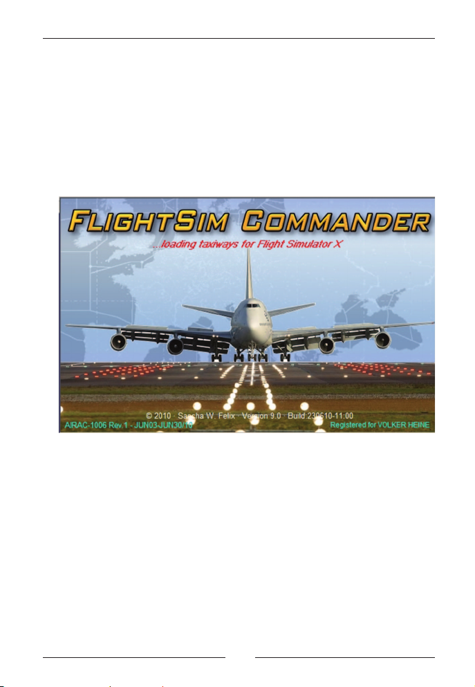
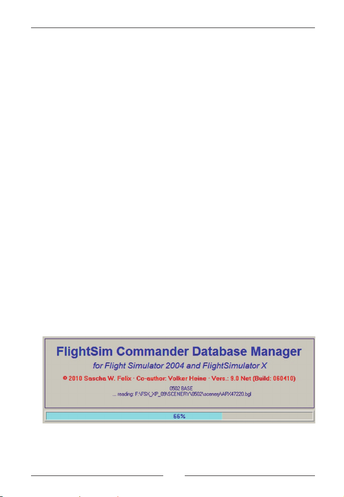
When you start FlightSim Commander afterwards, the following
introductory window will appear:
At the bottom of the picture you will find the version and build number
next to the copyright notice. The above screenshot comes from version
9.0. The currently loaded AIRAC cycle is dated FEB12-MAR 2009.
Notice that the data FlightSim Commander is using are stored in
databases which will be automatically loaded when the program is
started. The database currently being loaded is indicated in red letters
at the top of the window.
Once all databases have been loaded, the picture will disappear and a
new window will prompt you to select an airport at which you will fly.
Important: If you are using FlightSim Commander for both FS 2004
and FSX alternatively, the corresponding databases will be loaded
depending on the option set in the Options Window.
Aerosoft GmbH 2010
12 13
Page 13
If Flight Simulator is already running at the time you start FlightSim
Commander, you can also make a direct connection so that the map in
FlightSim Commander will show the airport or area where your aircraft
is located (for details see Directly connecting to Flight Simulator)
Database Manager
The Database Manager is a separate program which allows you to
create and update the databases used by FlightSim Commander.
You must run the Database Manager (FSCDbManager.exe),
before you use FlightSim Commander for the first time.
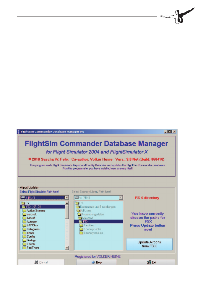
When you open the Database Manager the main window will look like
in the following screenshot:
Page 14
FlightSim Commander 9
Note that FlightSim Commander uses data which are partly extracted
directly from Flight Simulator files and partly from real-world databases. The data read from Flight Simulator directly are airports,
runways, ILS‘es, markers, taxiways, parking positions, and aprons.
All other data are provided by Navigraph (http://www2.navigraph.com/
www/fmsdata.asp) and concern VORs, NDBs, intersections, GPS fixes,
airways, SIDs and STARs, Transitions, airspaces and minimum safe
altitudes. Note that Navigraph provides monthly updates for these
databases. The collection of currently valid data is called AIRAC Cycle
followed by a date. The AIRAC cycle which you use appears at the
right bottom corner of the introduction screen when the program is
started.
After installation all databases from Navigraph are already present in
the \Database directory, but the databases created from Flight
Simulator directly (namely airport.fsc, taxi.fsc, poly.fsc as well as
regions.fsc, country.fsc, state.fsc, and city.fsc) are still missing, since
they depend on your specific configuration of Flight Simulator.
Therefore you have to run the Database Manager first to create these
files.
In principle, you will run the Database Manager only once to create
the necessary databases; however, if you have made any modifications
to your airports with programs such as AFCAD, or if you have installed
new airport sceneries, you should update the relevant FlightSim
Commander file and run the Database Manager again.
Aerosoft GmbH 2010
14 15
Page 15

Updating airport files
Since FlightSim Commander can be used with both Flight Simulator
2004 and Flight Simulator X, first of all you have to decide for which
version of Flight Simulator database files are to be updated.
Note that if you use both FS 2004 and FSX, you have to run the
Database Manager twice, once for each version. You cannot update
for both versions simultaneously. The order in which you update the
two versions of Flight Simulator is irrelevant.
Running the Database Manager will produce a log file which provides
a detailed record and analysis of all major data transfers and events
that happen during the installation process. If something goes wrong
with the Database Manager and you need help, please send us this log
file (FSCDBM_FS09.log and/or FSCDBM_FS10.log respectively).
In order to create the necessary database files FlightSim Commander
needs exactly two types of information:
7. drive and directory where your Flight Simulator is installed
8. drive and directory of your Scenery Library file (scenery.cfg)
For each of these two paths there is a separate drive/directory selection
box in the Database Manager labeled Select Flight Simulator Path here
and Select Scenery Library Path here respectively. In most cases all you
need to do is to select the Flight Simulator path. Everything else occurs
automatically.
Note, however, that Flight Simulator 2004 and Flight Simulator X
behave somewhat differently with respect to the structure of the
Scenery Library. Therefore in the following sections we will discuss the
various configurations separately.
Updating airports for FS 2004 on
a single computer
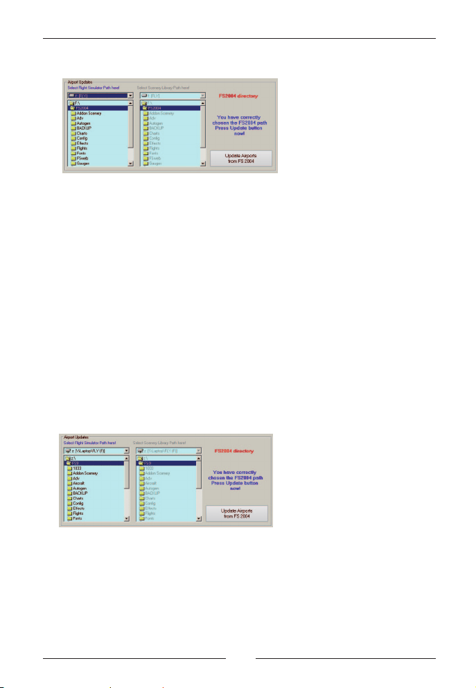
If you wish to update airports for FS 2004, all you need to do is to
select the drive and directory where FS 2004 is installed in the left
selection box.
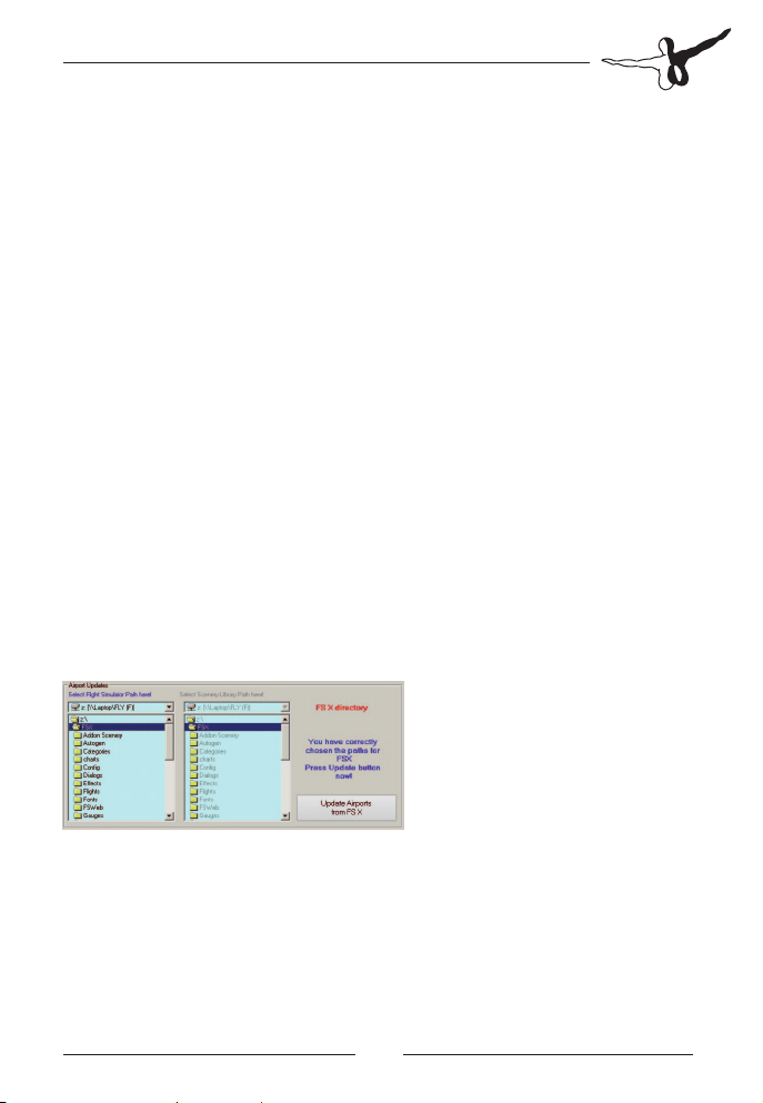
Page 16
FlightSim Commander 9
In the screenshot above FS 2004 is located on drive F:\ in the directory
FS2004. Notice that the Scenery Library selection boxes on the right
are automatically set to the same path and are grayed out, simply
because you don‘t have to select anything in those boxes.
At the same time the button shows Update Airports from FS2004 and
can now be pressed to begin the updating process.
Updating airports for FS 2004 in a network
If you run FlightSim Commander and Flight Simulator on two different
computers set up in a network and connected with Peter Dowson‘s
WideFS package, updating airports for FS 2004 is just as easy.
Simply select the network drive and directory where FS 2004 is
installed in the left selection boxes. Everything else will be exactly as in
a one-computer setup.
This screenshot is almost identical to the one in the preceding section
except that the FS 2004 folder is discernibly on a network drive.
VERY IMPORTANT: Please remember that the FlightSim Commander
computer must have access to the proper Flight Simulator drive and
Aerosoft GmbH 2010
16 17
Page 17
directory on the computer where Flight Simulator is installed. In other
words, your network must be properly set up and the necessary drives
and directories must be correctly mounted.
If you are not very much familiar with networks and their internal
structure, please read the Appendix at the end of this document.
Updating airports for FSX on a single computer
Updating airports for Flight Simulator X is a bit more complex for
reasons which unfortunately you need to understand.
In previous versions of Flight Simulator (including Flight Simulator
2004) the Scenery Library file scenery.cfg is located in the same
directory in which Flight Simulator itself is installed.
For reasons that even defy reasonable speculation this is no longer the
case for FSX. Instead, Microsoft has decided to place the Scenery
Library file deep down into the Windows System drive which in most
cases will be the C:\ drive. By default the Scenery Library file is placed
in C:\Documents and Settings\All Users\Application Data\Microsoft\
Fsx\.
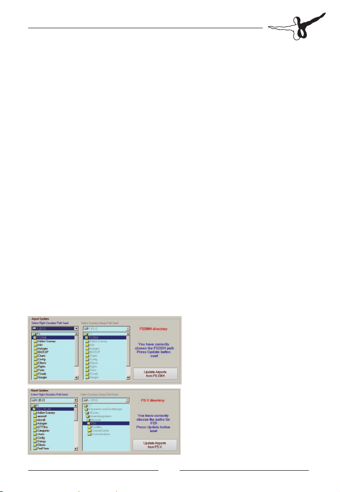
You will first select the Flight Simulator X path in the left selection box.
At this point the Database Manager will automatically set the Scenery
Library path in the right selection box.
Page 18
FlightSim Commander 9
In the screenshot above you see in the left selection box that FSX has
been installed in F:\FSX\. The right selection box has been automatically set to the Scenery Library path. There is nothing else you need to
do; just press the Update button to launch the updating process.
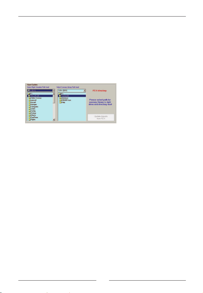
If for some reason the default Scenery Library path does not exist (a
few such cases have been reported), the two selection boxes will look
like this:
As before the left selection box shows the path for FSX. The right
selection box has been enabled and you are prompted to select path
for scenery library in right drive and directory box. At the same time
the Update button is still disabled because the Database Manager
doesn‘t know yet where to find your Scenery Library file scenery.cfg.
Now you need to search manually for the correct Scenery Library path
in the right selection box until the Update button becomes enabled.
Actually this latter case should almost never occur. However, some
users have reported that in their system the folder Microsoft in the
default Scenery Library path had a slightly different name, usually the
word Microsoft followed by a series of numbers and/or letters. The
possibility of selecting the Scenery Library path manually is thus a kind
of last resort measure.
Aerosoft GmbH 2010
18 19
Page 19
Updating airports for FSX in a network
Updating airports for Flight Simulator X in a network is appallingly
complex, again for some whimsical decisions made by Microsoft.
As described in the preceding section the Scenery Library file for FSX is
not only deeply embedded in the C:\ drive; what is still worse, it is
inside a partially hidden folder tree (Application Data) with extremely
limited access rights. In plain language this means that there is
absolutely no way of accessing the Scenery Library file from outside,
i.e. from another computer in a network.
In order to maintain the possibility of using FlightSim Commander in a
network with FSX, we decided on the following work-around.
The file scenery.cfg must be copied from the Scenery Library folder
C:\….Microsoft\FSX\ into the directory in which FSX has been installed.
Since we do not want to overwrite anything in the FSX folder, we copy
the file scenery.cfg (the one in the Scenery Library folder) renamed as
scenerycfg.fsc into the FSX folder.
In other words, if the Database Manager‘s left selection box is set to a
FSX folder in a network, it searches this folder for the presence of the
file scenerycfg.fsc. If that file is present, the button for the updating
process is enabled as in the screenshot below.
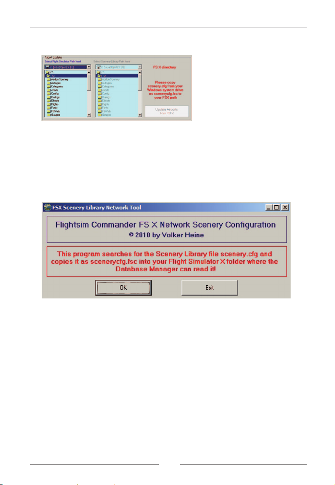
If the file scenerycfg.fsc is not found in the FSX folder, the following
configuration will appear prompting you to copy the file as described
above.
Page 20
FlightSim Commander 9
If you are familiar with copying files, you can copy the file manually as
described above. However, we have added a little Scenery Library
Network Tool (FSCFSXCFG.exe) which performs the copying process
for you.
Note that this program MUST be placed in your FSX folder and must
be started from there.
Simply press the OK button. You will be instructed when the copying
process has been successfully completed.
VERY IMPORTANT: Please remember that the FlightSim Commander
computer must have access to the proper Flight Simulator drive and
directory on the computer where Flight Simulator is installed. In other
words, your network must be properly set up and the necessary drives
and directories must be correctly mounted.
If you are not very much familiar with networks and their internal
structure, please read the Appendix at the end of this document.
Aerosoft GmbH 2010
20 21
Page 21
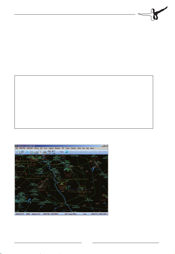
Map Window
The Map Window displays flight-relevant information on a geographic
map. Before you reach the Map Window, you will have to select an
airport which will then be located in the center of the map. If you have
made a flight plan, the departure airport will appear in the center.
The map displays:
VORs airports routes
NDBs taxiways coastlines
ILS'es aprons state boundaries
intersections gates & parking positions major rivers & lakes
GPS fixes markers airspaces
jet airways control zones minimum safe altitudes
victor airways AI traffic
The colors of the displayed objects can be changed and set up in the
Options Window.
Clock | Chart | Magnetic Var | Latitude/Longitude | Aircraft | FuelMouse Position
Page 22

FlightSim Commander 9
Clock: by clicking on this label you can toggle
between UTC and local time.
Chart: if you click on this label with the left mouse
button, you zoom in, with the right mouse
button you zoom out.
Latitude/Longitude: by clicking on this label you can toggle
between standard and decimal notation.
Flugzeug: clicking with the left mouse button on this
label opens the Aircraft Window; a right
mouse click toggles the Aircraft on Map
option (see also Navigating around the map).
Mausposition: this label has three functions: standardly the
latitude/longitude position of the mouse is
displayed. Clicking on it once changes the
display to inbound course and distance,
clicking again changes the display to outbound
course and distance. The two latter displays
relate to the position of your own aircraft or
to the center of the map depending on whether
or not you are connected to Flight Simulator.
Taxiways and airport ramps are also displayed, but are only visible if
the chart size is zoomed to 10NM or less. Taxiway designators appear
when you zoom down to 2 miles or less.
If you zoom in to 10NM or less taxiway identifiers and runway
identifiers are displayed next to the respective runway thresholds.
You can print the map by choosing Map -> Print Map on the menu bar.
Aerosoft GmbH 2010
22 23
Page 23

Navigating around the map
Mouse position
The rightmost label of the status bar shows the mouse position on the
map in terms of latitude and longitude. If you click on that label the
display changes to distance and course relative to the center of the
map or, if you are connected to Flight Simulator, to the position of
your own aircraft. This way you can quickly measure distances and
headings by simply moving the mouse.
Moving around the map
You can move around the map by clicking with the mouse on any
geographic point which will then become the center of the map.
Alternatively, you can either choose Go to airport from the Window
menu or press the button Go to airport, if you wish to move to the
location of a specific airport.
Compass
When you press the button with the compass rose, a compass will
appear on the map. If you are connected with Flight Simulator, the
compass will also indicate the heading of your aircraft.
Page 24
FlightSim Commander 9
Rubber band selection
To zoom in on a particular area of the map, you can use the rubber
band function. While you hold the left mouse button pressed, use the
mouse to draw a rectangle around an area of your choice. As you release
the mouse button again, the map will zoom in on the area selected.
Information label
If you wish to obtain more detailed information on a particular navaid,
airport, intersection, etc. move the mouse to the corresponding
position and let it stay there for a second. A label will open displaying
information on the object selected. If more than one object is located
at a particular position, all objects will be named.
Airspaces have a fat dot in one of their corners. To identify a particular
airspace and to obtain detailed information on it, hold the mouse
pointer over this dot.
Aerosoft GmbH 2010
24 25
Page 25
Information labels can also be opened on AI aircraft. Move the mouse
to the root of the small aircraft symbol indicating the aircraft’s
heading. The label then displays the airport, city, and country of the
aircraft’s departure and arrival.
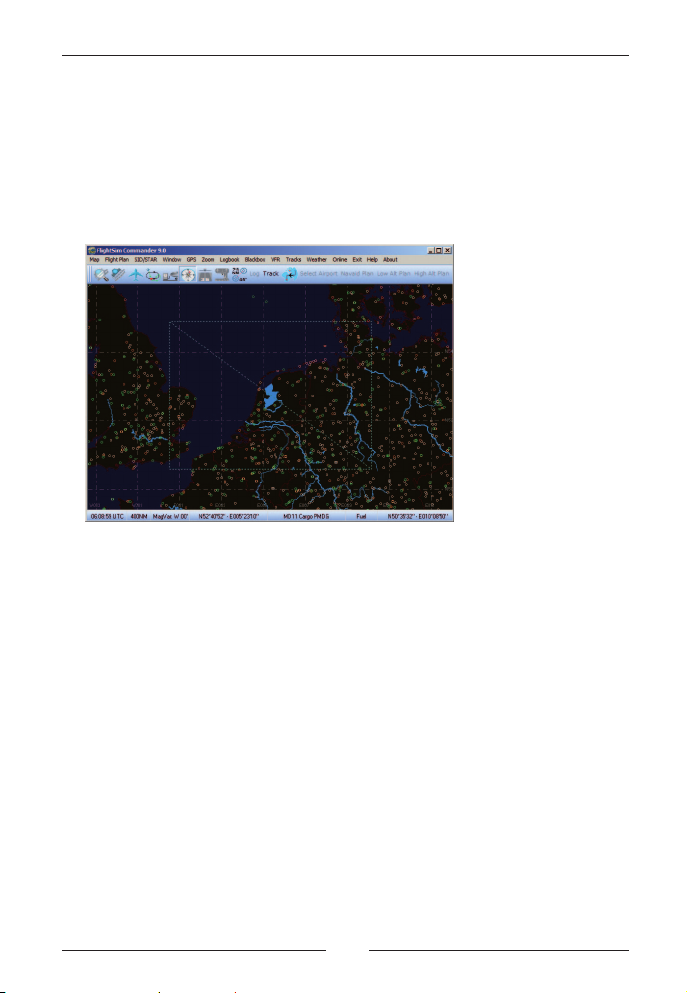
Aircraft (always) on Map
When you are connected to Flight Simulator, the little aircraft symbol
will move along the map following your geographic positions. By
default the map display will switch to a new position as soon as the
aircraft approaches any of the borders of the map. Therefore, the
aircraft symbol will always be visible somewhere on the map.
As a consequence, you cannot have a part of the world displayed on the
map that is very far away from your current geographic position; e.g. you‘re
flying somewhere in Italy, but you want to see something in Sweden.
If you de-select the Aircraft on Map menu item, you can move to any
part of the world via mouse clicks irrespective of where your aircraft is
currently located.
Alternatively, you can also right-click the aircraft status label to toggle
this option.
Page 26

FlightSim Commander 9
Always on Top
When you are running FlightSim Commander connected with Flight
Simulator, you are running, in fact, two programs at a time. Standardly,
only the program that has focus will be visible on the screen, while the
other is hidden behind the window with focus.
As a consequence, as Flight Simulator receives focus, the FlightSim
Commander window will no longer be visible, because it hides behind
the Flight Simulator window and can be called back only by pressing
its representation on the task bar.
If you want to have the FlightSim Commander window always visible,
i.e. on top of the Flight Simulator window, choose Map -> Always on
top from the menu bar. You will probably use this option, if you are
running both programs on the same computer and on one and the
same monitor.
Important: You should also uncheck the option pause on task switch
in Flight Simulator’s Option window which by default is checked. If this
option is on, Flight Simulator will pause each and every time the focus
is on FlightSim Commander. Obviously, this can be very annoying.
Zoom
You can zoom and unzoom the map by pressing Page↓ and Page↑ or +
and - on your keyboard. For larger steps choose a value from the
Zoom menu. As a further possibility you can left-click or right-click on
the Chart status label.
Aerosoft GmbH 2010
26 27
Page 27
Zooming and unzooming by pressing Page↓ and Page↑ or + and - is a
general convention in FlightSim Commander and applies to all other
graphic displays of the program as well.
Alternatively, you can press the buttons with the magnifying glasses on
the button bar on the left-hand side of the map. Using these buttons
is preferable when you are connected to Flight Simulator because the
focus is immediately returned to FS (for details see section GPS and
Moving Map).
The Autozoom option in the Zoom Menu will automatically zoom
down to 3 miles when you are on the ground and back to 50 miles
when you are airborne. This may be helpful after departure and
landing when you are busy controlling the aircraft. Autozoom is
automatically canceled when you zoom in or out manually.
Page 28
FlightSim Commander 9
Buttons
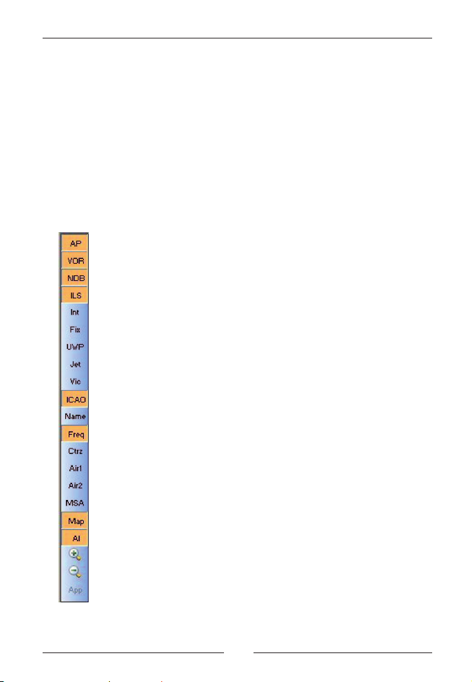
Display buttons
If you move the mouse to the left side of the map you see a series of
buttons which allow you to toggle the display of the map. The buttons
will disappear as soon as you move the mouse to any other area.
Green letters on the buttons indicate that the option is on, red letters
that the option is off.
toggles the display of Airports
toggles the display of VORs
toggles the display of NDBs
toggles the display of ILS'es
toggles the display of intersections
toggles the display of GPS fixes
toggles the display of user waypoints
toggles the display of high altitude (jet) airways
toggles the display of low altitude (victor) airways
toggles the display of ICAO codes
toggles the display of names
toggles the display of frequencies
toggles the display of control zones
toggles the display of CTA airspaces
toggles the display of FIR airspaces
toggles the display of minimum safe altitudes
toggles the display of the coastline map
toggles the display of AI aircraft
zooms the map
unzooms the map
shows the approach path for each runway
Aerosoft GmbH 2010
28 29
Page 29
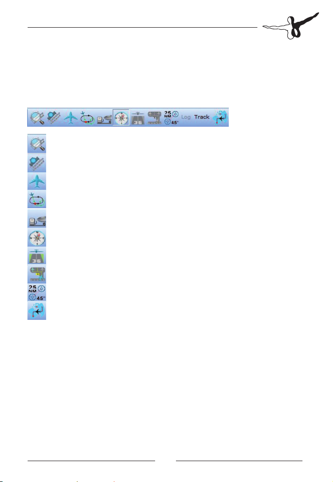
Function buttons
Above the map and below the menu bar you find a series of graphic
buttons which allow you to either open a window or make a flight
plan selection
opens the Airport Information Window
go to a specific airport
opens the Aircraft Window
opens the Holding Window
opens the Fuel Window
displays the Compass
opens the Approach Window
selects parking position and taxiways
activates the measuring tool for distance and course
opens the Flight Plan Panel
The remaining buttons with worded labels are largely self-explanatory
and will be dealt with in detail in the section on flight planning
techniques.
Page 30

FlightSim Commander 9
Intersections and airspaces
Intersections and fixes
Intersections can be displayed selectively. If the button Int is on, all
intersections will be shown. If the button Int is off and the button Vic
is on, then victor airways and only the intersections on these airways
are shown. Similarly, if the button Int is off and the button Jet on, then
jet airways and only the intersections on these airways are visible.
If a flight plan involves GPS fixes, these will also be displayed irrespective
of whether or not the button Fix is on.
Note that we make a terminological distinction between intersections
and GPS fixes. Intersections are waypoints on an airway, while GPS
fixes are merely geographic locations defined in terms of latitude and
longitude without having anything to do with airways.
Airspaces
FlightSim Commander can display 12 different types of airspaces
which can be toggled on and off by choosing the corresponding entry
in Map -> Airspaces. The display of control zones can also be toggled
by pressing the button Ctrz in the vertical button bar. Likewise the
buttons Air1 and Air2 toggle CTA and FIR airspaces respectively.
The airspaces that can be displayed are:
• Advisory Area (ADA)
• Air Defense Identification Zone (ADIZ)
• Air Route Traffic Control Center (ARTCC)
• Area Control Center (ACC)
• Buffer Zone (BZ)
• Control Area (CTA)
• Control Zone (CTLZ)
• Flight Information Region (FIR)
• Ocean Control Area (OCA)
Aerosoft GmbH 2010
30 31
Page 31

• Radar Area
• Terminal Control Area (TCA)
• UpperFlight Information Region (UIR)
AI traffic and TCAS
FlightSim Commander can display both airborne and ground AI traffic
while you are connected to Flight Simulator. If you zoom down to 5
NM or less both ground and airborne traffic will be displayed, otherwise
only airborne traffic will show.
AI aircraft are represented as little aircraft symbols indicating the
aircraft‘s course and an accompanying label. What this label displays
can be set in the GPS -> AIInfo menu. For airborne traffic tail number,
flight level, ground speed, and/or departure and arrival airport can be
shown. For ground traffic the label may show tail number and/or
destination airport.
Important: Whether the field ATC ID displays the aircraft‘s tail
number or flight number must be set in the FSUIPC Menu of Flight
Simulator and cannot be controlled inside FlightSim Commander.
While you run Flight Simulator choose Modules -> FSUIPC from the
menu bar. Choose the Technical card. At the bottom right corner you
find Set TCAS id string from; make a selection. Also, make sure that
the value for Limit TCAS range is set to 0.
AI aircraft may appear in four different colors which are by default:
green: aircraft is tuned to the same frequency as you
yellow: aircraft is not tuned to the same frequency as you
orange: with respect to your own position the aircraft is closer than
15 NM at a flight level difference of less than 1500 ft
(airborne traffic only)
red: aircraft is less than 3NM from you and flying towards you
(airborne traffic only).
The colors can be changed in the Options Window.
Page 32

FlightSim Commander 9
If an airborne AI aircraft approaches your aircraft within less than 3
NM a TCAS warning label appears on the map accompanied by an
acoustic beep. The beep can be turned on and off by choosing GPS ->
TCAS Sound.
Tools
Select parking & taxiways
FlightSim Commander offers you the possibility of highlighting
selected parking positions and taxiways in order to facilitate airport
taxiing.
Choose Windows -> Select Parking & Taxiways or press the button
with the parking aircraft. In the opening window choose the departure
or destination airport at your discretion.
You can select a parking position in the left-hand list box. This position
will be highlighted on the map with the color chosen in the Options
Window. Only one parking position can be selected at a time.
In the right-hand list box taxiways are selected for highlighting. This
feature may be useful if you are instructed by ATC to use certain
Aerosoft GmbH 2010
32 33
Page 33

taxiways to reach your gate or the runway. Multiple selection of
taxiways is possible.
This feature is only available if you are connected to Flight Simulator.
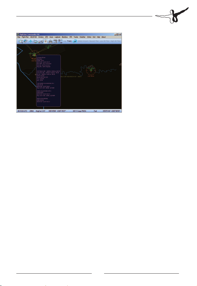
Runway approach path
The button App allows you to display an approach path from the last
waypoint to each of the runways of the destination airport. The
picture below shows the path from VOR Cola to Rwy 24 of Cologne
Airport (EDDK).
If a missed approach for that runway is available, it will also be
displayed.
For each runway press App again. Obviously, this option is only
available after you have filed a flight plan.
Page 34

FlightSim Commander 9
Note that pressing the App button standardly toggles through all
runways. However, if your flight plan contains a transition, only the
approach that corresponds to that transition will be displayed.
Measuring distance and course
If you click on the button to the left of the two buttons Log and Track,
you will notice that the button stays pressed and thereby activates the
measuring mode.
In this mode you can measure distance and course between two
arbitrary points. Use the mouse and the left mouse button to draw a
line between any two points. A label becomes visible indicating
distance and course between the points selected.
Finding a map object
Do you know where airport UKLN or VOR TOE are located? Or would
you like to know where high altitude airway Y20 is running? FlightSim
Commander allows you to easily find any object on the map. Choose
Map -> Find Object on the menu bar. Select the type of object with
the option buttons on the right hand side of the window. Then type in
the code and press Enter (or Find). All objects with this code will then
appear in the list box. Select the object you wish to find from the list
where latitude and longitude values facilitate identification of the
proper object. The lower list shows more detailed information, if you
click on an entry in the upper list.
If you have checked Close window after selection, the window will
Aerosoft GmbH 2010
34 35
Page 35

automatically close and the object searched for will appear in red on
the map. Otherwise you need to press the button Close. To undo the
selection on the map, press Esc on your keyboard. Note that only
those objects can be selected which also appear on the map; the
option buttons for the other objects are grayed out.
If Show item on map directly after selection is checked, then the map
display will jump to the selected item immediately after selection.
The two buttons Inbounds and Aircraft are special-purpose options for
IVAO and VATSIM controllers. If you choose Inbounds and type in an
airport ICAO code, all inbound flights for that airport will be listed.
Similarly if you choose Aircraft and type in (part of) a call sign, then all
aircraft whose call signs contain the string will be listed.
Transferring frequencies to Flight Simulator
This feature is obviously only available, when you are connected to
Flight Simulator.
You can transfer the frequency of any VOR, NDB, or ILS displayed on
the map to the corresponding instruments in Flight Simulator by
clicking on the navaid with shift-left mouse button.
In the case of VORs and NDBs you should click near the center of the
graphic symbol, for ILS click near the spot where the ILS hits the runway.
VOR and ILS frequencies will be sent to Nav1, NDB frequencies to ADF1.
Notice that the Frq button on the button bar must be on so that
frequencies can be seen in the label.
This feature does not work for PMDG and other FMC-equipped aircraft.
Page 36

FlightSim Commander 9
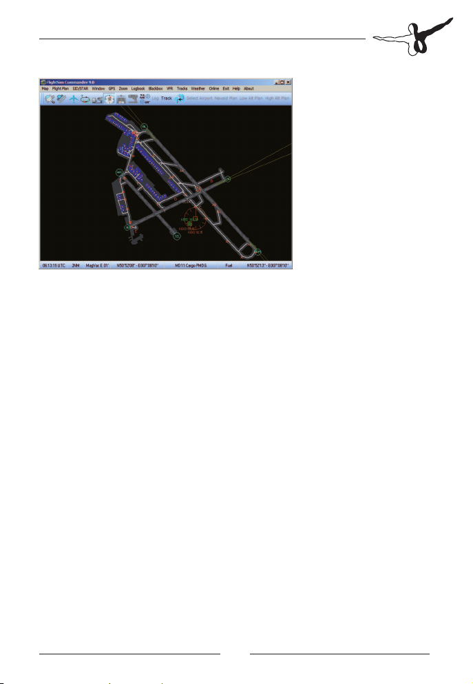
Airport Information
The Airport Information Window allows you to take a quick look at
the layout of airports and their associated runways.
You reach the Airport Information Window by clicking on
the button with the airport layout icon or by choosing
Window -> Airport Information on the menu bar.
As usual, you can zoom and unzoom this display by pressing Page-↓
and Page-↑ or + and - on your keyboard.
Aerosoft GmbH 2010
36 37
Page 37

Flight planning
FlightSim Commander offers a very sophisticated and complex flight
planning system in which you can combine various types of automatic
and manual planning supplemented by SIDs, STARs, transitions,
individual waypoints, etc. We will first present basic flight planning
methods and then proceed to discuss more advanced techniques.
Flight plans are created and displayed on the flight plan panel which
opens when you press the button to the left of Select Airport. You can
use this button at any time to show or hide the flight plan panel.
The flight plan panel is a separate, undockable window. Press the
button with the key symbols at the right-hand side to undock and
re-dock the window. When the window is undocked, you can expand
its height with the mouse. This may be useful for longer flight plans, if
you want to see all waypoints at the same time.
Whenever you want to discard an old flight plan and create a new one
choose Flight Plan -> New from the menu bar. If you have already filed
a flight plan, but for some reasons find the route inappropriate, you
can choose Flight Plan -> Delete Enroute Waypoints. This will set the
stage for a new flight plan, except that the departure and arrival
airports are kept so that you do not have to re-enter them.
Page 38

FlightSim Commander 9
Basic techniques
Any flight plan involves the following obligatory specifications:
• a departure airport
• a destination airport
• a route; i.e. how you want to get from the departure to the
destination airport
Since the route trivially depends on the departure and destination
airports, the first step in creating any flight plan will be to select these
two airports.
A simple flight plan: selecting
departure and arrival airports
There are two ways of selecting the departure and arrival airports.
First, you can choose the airports from the airport list:
1. press the button Select Airport in the button bar
2. click on the option button Departure
3. select the airport from the list
4. click on the option button Destination
5. select the airport from the list
Alternatively, you can select the airports directly on the map. Note that
the first airport selected will be interpreted as being the
departure, the second as being the arrival airport. Furthermore
you can only select airports and waypoints from the map, if the flight
plan panel is visible.
1. click with the right mouse button on the departure airport on
the map. A popup menu opens with the ICAO code of the
airport.
2. click with the right mouse button on the arrival airport on the
map. A popup menu opens with the ICAO code of the airport
Aerosoft GmbH 2010
38 39
Page 39

Above the airport name you see a little circle; this indicates the ARP
(airport reference point) where you should click with the right mouse
button.
After you have made these selections, the two airports will appear in
the flight plan table. In addition, the runways and parking position of
the departure airport are listed in the box on the right-hand side of the
table.
Once you have selected the two airports, the flight plan panel will look
something like this:
The next step is optional for reasons explained below. Click on the
button with the list symbol at the right-hand side of the flight plan
panel. The Waypoint Window opens. The list shows all runway and
parking position of Frankfurt airport. Choose any position you like. We
decided to select Gate V 92. To close the window, press the button
with the list symbol again.
Page 40

FlightSim Commander 9
Important: The selection of a departure position (runway or parking)
has no effect whatsoever within FlightSim Commander. However,
Flight Simulator requires a departure position in its flight plan format.
Therefore, if you intend to save a flight plan to be loaded again in
Flight Simulator, you should use a proper departure position which
determines where your aircraft is to be positioned. In all other cases
you may ignore this step.
What we have achieved so far is the simplest flight plan possible. The
flight starts at EDDF Gate V 92 and goes directly to EDDL without any
intervening waypoints. You can save this flight and load it again in
Flight Simulator if you like.
Note that a flight plan is always created for the aircraft currently
selected. The values for speed and flight level which appear at the
bottom of the flight planning panel depend on the aircraft you have
selected.
If you wish to use some other aircraft, go to the Aircraft Window and
make the proper selection. You open the Aircraft Window by pressing
the button with the aircraft symbol.
Adding waypoints to a flight plan
In most cases you probably don‘t want to go directly from airport to
airport, but rather choose a route of intermediate waypoints. The most
convenient way is to let FlightSim Commander automatically find an
appropriate route for you. There are three types of routes you can choose:
• navaid route (leads you from VOR/NDB/intersection
to VOR/NDB/intersection)
Aerosoft GmbH 2010
40 41
Page 41

• low altitude route (leads you along low altitude (victor)
airways)
• high altitude route (leads you along high altitude (jet)
airways)
After you have selected your departure and arrival airports you simply
click on any of the three buttons Navaid Plan - Low Alt Plan - High Alt
Plan which are located on the button bar above the map. FlightSim
Commander will subsequently calculate a complete route leading from
your departure to your arrival airports.
Navaid plan with VOR waypoints
Navaid plan with NDB waypoints
The two pictures above show a navaid-to-navaid route from EDDF
(Frankfurt/Main, Germany) to EDDL (Düsseldorf, Germany). Note that
the routes differ with respect to the types of navaids that appear as
waypoints. In the first plan all waypoints are VORs while in the second
they are NDBs.
Which type of navaids FlightSim Commander considers depends on
which are visible on the map and visibility is toggled by the display
buttons (see also Buttons) on the left side of the map. If you want only
Page 42

FlightSim Commander 9
VORs in your flight plan, then the VOR button should be on, while the
NDB button and intersection button should be off. Similarly, if you
want only NDBs, only the NDB button should be on. If more than one
of the three buttons is on, then FlightSim Commander will consider all
visible navaids (those with the button on) giving priority to VORs over
NDBs over intersections.
The following flight plan shows a low altitude route from EDDF to
EDDS. Note that after the waypoint the name of the airway as well as
altitude restrictions appear in parentheses.
Low altitude flight plan with intersection waypoints
Of course, you can press the three buttons one after the other to see
which flight plan you like best.
Selecting waypoints manually
In the preceding sections we had FlightSim Commander select the
waypoints of a route. While this is the most convenient way of
generating a flight plan, you can also select waypoints one after the
other manually.
As in the case of airports there are two ways of adding a waypoint to
the flight plan: selecting it from a list or on the map.
• On the map you can click with the right mouse button on the
waypoint (VOR, NDB, Intersection, GPS fix, or user waypoint) to
be selected. This waypoint will subsequently appear in the
flight plan table with all the relevant information.
Aerosoft GmbH 2010
42 43
Page 43

• You can type the code of the waypoint to be selected into the
waypoint text box and press Enter on your keyboard. All
waypoints with this code will appear in the waypoint list.
Choose the appropriate waypoint by clicking on it.
To select a waypoint from a list, click on the button with the table
symbol on the right-hand side of the flight plan panel. Choose the
Waypoint tab of the window. Type <WLD> into the text box.
The list box now displays all waypoints whose first three letters begin
with <WLD>. The latitude/longitude values are for easier identification.
Note that WLD is fivefold ambiguous. There are three waypoints (VOR,
NDB, intersection) at N31° - E014° and two waypoints (VOR and
intersection) at N48° - E011°. Since we are filing a flight plan for a
route inside Germany, only the latter two are relevant. We decide to
choose the VOR and thus click on the second line of the list. The
resulting flight plan looks like this:
If you want to select the VOR WLD directly on the map, you click with
the right mouse button on the center of the VOR symbol. A popup
menu appears showing that at this location there are both a VOR and
intersection WLD. We choose the VOR.
Page 44

FlightSim Commander 9
Note that as a basic technique you must enter the waypoints in
the correct order, i.e. in the order from departure to arrival. If you
have mistakenly selected a wrong waypoint, you can delete it again.
How you delete a waypoint will be discussed later.
Of course, FlightSim Commander also allows you to insert a waypoint
or sets of waypoints in any arbitrary order, but we will discuss these
more advanced techniques of flight planning in a later section.
AFIL (air filed) and ZZZZ flight plans
Standardly flight plans lead from a specific departure airport to a
specific destination airport. Apart from these standard flight plans
there are also the so-called AFIL- and ZZZZ- flight plans.
An AFIL flight plan is filed while you are airborne and leads from your
current position to the destination airport. A ZZZZ flight plan is created
prior to the actual flight with departure and destination being not only
an airport, but also a geographical position.
AFIL and ZZZZ flight plans can be combined with each other; for
example, if a VFR pilot decides to continue his flight under IFR (e.g.
due to specific weather conditions) and therefore has to file a flight
plan. In this case he will file an AFIL flight plan which will lead from his
current position to either a destination airport or to some other
Aerosoft GmbH 2010
44 45
Page 45

geographical position (ZZZZ).
To file an AFIL flight plan, proceed as follows:
3. Open the flight plan panel (if this is still closed)
4. Press the button Select Airport
5. Enter AFIL into the ICAO text box and press Enter or press the
button Search by ICAO code. The airport list shows from
current location.
6. Press the button Select.
7. Enter the destination airport as usual
8. Select waypoints as usual
The following screenshot shows an AFIL flight plan which leads from
the current position to the airport St. Hubert (EBSH) passing NDB SLV.
AFIL to EBSH
To create a ZZZZ flight plan proceed as follows:
9. Open the flight plan panel (if this is still closed)
10. The geographical position is selected on the map by clicking
with the right mouse button on some point of the map.
Page 46

FlightSim Commander 9
If a geographical position is selected for a new, as yet empty flight
plan, then this mouse click will be interpreted as departure. A popup
menu opens with only one entry <ZZZZ Plan>. If some departure has
already been chosen, then the mouse click will be interpreted as
destination. There are thus three possibilities for a ZZZZ flight plan.
11. from a geographical position to a destination airport
12. from a departure airport to a geographical position
13. from a geographical position to some other geographical
position
The following screenshots illustrate these three possibilities
ZZZZ to EDDK
Aerosoft GmbH 2010
46 47
Page 47

EDDK to ZZZZ
ZZZZ to ZZZZ
SIDs, STARs and transitions
Inserting SIDs, STARs, and transitions
In many cases you might want to use Standard Instrument Departures
(SIDs) and/or Standard Arrival Routes (STARs) for your flight plan. This
is extremely simple.
Choose SID/STAR -> SID -> Select from the menu bar to open a SID.
For a STAR choose analogously SID/STAR -> STAR -> Select. For a
transition choose SID/STAR -> Transition -> Select. If no SID, STAR or
Page 48

FlightSim Commander 9
transition for a given airport is available the corresponding menu entry
will be deactivated and thus be gray.
The following window opens in which you can select any number of
SIDs/STARs/transitions from the list box.
The SIDs/STARs/transitions selected will immediately be displayed on
the map so that you can easily decide which one will be the most
appropriate one for your flight.
For example, the following screenshot displays all SIDs for runway 33
of Hamburg airport (EDDH):
To undo the display of SIDs/STARs/transitions uncheck the menu item
SID/STAR -> SID -> Display or SID/STAR -> STAR -> Display or SID/STAR
-> transition -> Display.
Aerosoft GmbH 2010
48 49
Page 49

If only a single item in the list box has been selected, the button Add
to plan becomes active. Pressing this button will insert the waypoints
of the SID/STAR/transition into your flight plan.
After you have selected a SID, a sample flight plan from Frankfurt
(EDDF) to Stuttgart (EDDS) may look like this:
You can tell by the symbols in the left column of the table that RID and
ANEKI are not ordinary enroute waypoints, but rather belong to a SID.
The background color for the SID, STAR, and transition symbols is
bluish while it is green for enroute waypoints. More specifically, the
following symbols occur in the flight plan table (from left to right):
Enroute: VOR, NDB, intersection, GPS fix,
user waypointt
SID/STAR/Trans VOR, NDB, intersection, GPS fix,
user waypoint
Note that you can choose SIDs and/or STARs at any time during the
flight planning process. That is, you can insert a SID and/or a STAR
either before or after the remaining route has been generated.
However, we recommend that you select the SID and/or STAR before
deciding on the remaining flight plan, because the result will be
different for an airport with or without a SID (STAR or transition
analogously).
If no SID has been selected, then the route will be created starting
with the airport reference point as point of departure; however, if a
SID has been selected, then the last waypoint of the SID will be the
point of departure for the enroute route. Consequently, if you select
the SID or STAR after generating the route, we suggest that you press
the relevant flight plan button again in order to get a reasonable
result.
Page 50

FlightSim Commander 9
The following screenshot shows the flight plan and route after a
transition has been added:
A further comment on SIDs and STARs
There are a number of common misunderstandings about SIDs and
STARs which are quite frequent among flight simmers and which need
to be clarified.
Some users have asked in the past whether or not it is possible in
FlightSim Commander to define your own SIDs and STARs or whether
the user can modify a given SID or STAR according to his needs or
likings.
The answer is a very strict no! SIDs and STARs are specific route
segments which have been defined and published by official aviation
authorities and thus they exist only in exactly the way they have been
published. If you modify a SID by adding or deleting waypoints, then
this is no longer a SID. It may be a reasonable departure route, but not
a SID because you‘re not the relevant aviation authority. Similarly, you
simply cannot define your own SID or STAR for precisely the same
reason. You can define a departure or arrival route, but not a SID or
STAR. Any ideas about modifying or defining SIDs and/or STARs are
„as unreal as it gets“.
Aerosoft GmbH 2010
50 51
Page 51

This has a number of consequences for the flight planning process.
While you can delete any enroute waypoint, you cannot delete a
waypoint inside a SID or STAR. You can delete the entire SID or STAR
by choosing SID/STAR -> SID -> Delete or STAR -> Delete from the
menu bar, but not individual waypoints. Similarly, you cannot insert a
waypoint into a SID or STAR. SIDs and STARs are unitary entities which
can only be manipulated as a whole. The same holds for transitions
analogously.
However, if your departure or arrival airport does not have a SID or
STAR listed in the database, you can nevertheless define (and save for
later use) your own departure and/or arrival route. How this is done is
explained in details in the section on route segments.
Custom waypoints
Selecting custom waypoints
Standardly, your flight plan will be made up of „official“ waypoints
such as VORs, NDBs, intersections and GPS fixes.
VORs and NDBs are radio stations which emit a certain frequency.
Intersections and GPS fixes have no frequency, but are simply geographic
points with a name defined in terms of latitude and longitude. In our
terminology intersections are waypoints which are located on an
airway, while GPS fixes are geographic points which have nothing to
do with airways and are usually located near airports for GPS-controlled
departures and landings.
Apart from these „official“ waypoints, you can also create within your
flight plan custom waypoints which again are defined in terms of
latitude and longitude and which will automatically be assigned a
name consisting of „Fix“ plus a number indicating their position within
the route; e.g. Fix01, Fix02, Fix03, etc. Note that these custom
waypoints exist only in your flight plan.
Page 52

FlightSim Commander 9
Do not confuse these custom waypoints with the user waypoints
which are permanently stored in a separate database and which are
treated in much the same way as any other waypoint.
To create a custom waypoint, move the mouse to the desired geographic
location and then click with the right mouse button. A popup menu
appears with the entry <Virtual Waypoint here>. If you click on the
menu, the waypoint will then appear in the flight plan table as in the
picture below:
Of course, you can insert any number of custom waypoints, as
illustrated in the screenshot below. Note that all virtual waypoint are
called Fix with a number afterwards which refers to its position within
the flight plan.
Custom waypoints with precise location
If you work with official charts such as Jeppesen’s Airway Manual or
country-specific AIPs you might need to add a custom waypoint to
your flight plan which has a very precise location frequently defined in
terms of radial and heading with respect to some other waypoint.
Aerosoft GmbH 2010
52 53
Page 53

Let’s look at such a case by way of example. The AIP Germany has a
departure route for runway 14L of EDDK (Cologne/Bonn) which reads like
this:
On track 139° to 5 DME KBO or 1500, whichever is later, LT, on
R278 COL to COL
In plain language this instruction says the following: after takeoff from
14L fly runway heading which is 139° until you reach a point which is
5 NM away from VOR KBO (Köln/Bonn) and is located on radial 278 of
VOR COL (Cola). When you reach exactly this point, turn left and fly to
VOR Cola.
In terms of flight planning the first official waypoint after EDDK is VOR
COL (Cola). But between EDDK and COL there is this virtual waypoint
up to which you fly runway heading and at which you turn left toward
COL. One way to fly the exact route would be to simply set your Nav1
and Nav2 properly and turn left when your instruments indicate that
you have reached that point.
But you could also insert a custom waypoint which is precisely located
as defined in the AIP instructions.
This is how you proceed.
First you file a flight plan from EDDK to your destination (e.g. EDDH)
with an initial waypoint COL. At this point your flight plan table will
look like this:
Now you want to insert a custom waypoint between EDDK and COL.
First, you highlight the first row of the table (EDDK) by clicking on it.
This indicates that the custom waypoint will be inserted directly after
Page 54

FlightSim Commander 9
EDDK (see also the general insertion rule in the following section A
sample flight from EDDH to ESSA).
Now you must find the exact location with the mouse. Note that
below the waypoint box a line appears with information on distance,
heading, and radial of your current mouse position.
EET: 00:33 DTG: 211 TAS: 480 FL: 370 SID: 5,4NM/HDG: 131°/RDL: 339°
Move the mouse until the value for heading is 139 and the value for
radial is 278. At exactly this location you are 5NM away from EDDK
with a heading of 139° and on radial 278 of VOR Cola.
If now you click with the right mouse button on this location, a
custom waypoint will be inserted which corresponds exactly to the AIP
instructions. Note that distance and heading refer to the previous
waypoint (here: EDDK), while radial refers to the next waypoint (COL).
On the map you get something like the following picture:
Aerosoft GmbH 2010
54 55
Page 55

Editing the flight plan table
There are essentially three options to edit the waypoints of a flight
plan. These are illustrated in the following screenshot:
You select a waypoint by clicking with the left mouse button on the
corresponding row. In the above screenshot the intersection OSN has
been selected. When you now click with the right mouse button on
the same row, a popup menu with three options opens.
Obviously you want to be able to delete a waypoint. You would
choose the top menu entry to delete intersection OSN.
The second entry reads <Insert waypoint BEFORE Int OSN>. What does
this mean?
As a general rule a new waypoint will always be inserted after the
waypoint in the selected table row. If you wish to insert the new
waypoint before the one in the selected table row, then you choose
this option.
Why this option? In the majority of cases it does not make much of a
difference whether you insert a new waypoint before or after the one
selected in the table, since both procedures are logically equivalent.
However, there are some cases in which the default insertion-after rule
is difficult to handle. Suppose you are planning a long distance flight
from EDDF (Frankfurt/Germany) to KORD (Chicago O’Hare/USA). We
assume that you have already selected the two airports. Suppose
furthermore that you want to select the first waypoint after departure
(say TAU, northwest of the airport) and the last waypoint before arrival
(e.g. OBK, north of Chicago) manually.
There is no problem selecting TAU with the default insertion rule. But
selecting OBK is cumbersome. By the default rule you would have to
first select TAU in the table for OBK to be inserted after it. But
Page 56

FlightSim Commander 9
selecting TAU in the flight plan table moves this waypoint to the center
of the map and there is no way of seeing the area around Chicago
unless you zoom out to about 4000 NM in which case selecting the
new waypoint is virtually impossible.
Actually what you want is to select KORD in the flight plan table so
that this airport will be in the center of the map. Subsequently, you
want to select the desired waypoint as usual. But this is tantamount to
inserting OBK before TAU so that in this specific case you would press
the Alt key when selecting KORD in the table.
Furthermore, most FMCs use the insertion-before rule so that users
with a strong FMC background might want to prefer the same
procedure in FlightSim Commander.
Note also that the insertion-before option applies only to the next
waypoint to be selected. After you have selected the next waypoint,
the program switches back to the insertion-after rule.
The final option allows you to delete all waypoints between the
departure airport and the selected waypoint. Suppose you have left
your departure airport heading for the first waypoint when ATC
instructs you to go directly to OSN; i.e to skip all waypoints before
OSN. Without this option you would have to individually delete all
waypoints before OSN. If you have a flight plan with several dozen
waypoints, this would consume a long time during which you can‘t
focus on your job as a pilot. To comply with ATC‘s instruction quickly,
you use this third option.
Note that not all options are available for all waypoints. In the
following screenshot the destination airport EDDH has been selected.
First of all, you cannot delete an airport. Secondly, it does not make
sense to delete all waypoints between departure and destination. If
this is what you want you might, in fact, choose the menu Flight plan
-> Delete Enroute Waypoint
Aerosoft GmbH 2010
56 57
Page 57

The following screenshot shows that you cannot delete an individual
waypoint of a SID, but only the entire SID. Therefore popup menu
looks slightly different, when you select a waypoint of a SID (or STAR
or transition). See also the section on SIDs, STARs, and transitions.
Deleting an old flight plan and creating a new one
If you want to delete the current flight plan in order to create a new
one, choose Flight Plan -> New on the menu bar. This option empties
all tables, labels and boxes and makes FlightSim Commander ready for
a new flight plan.
If you have already filed a flight plan, but for some reasons find the
route inappropriate, you can choose Flight Plan -> Delete Enroute
Waypoints. This will set the stage for a new flight plan, except that the
departure and arrival airports are kept so that you do not have to
re-enter them.
Printing flight plans
You can print any flight plan previously filed. Choose the menu Flight
Plan -> Print Plan.
Note that the printed version of a flight plan is much more detailed
than what you see in the flight plan table on the screen.
The printed flight plan consists of three different parts which can be
chosen selectively:
• General Flight Information
this part contains information on fuel, departures and arrival
routes, frequencies, etc.
Page 58

FlightSim Commander 9
• Waypoint List
this list shows all the waypoints in much the same way as in
the flight plan table on the screen.
• Control Zone Information
this information is primarily for VFR pilots as it lists all control
zones which the filed route may potentially cross.
Advanced techniques
With the basic techniques discussed in the preceding sections we have
always created a unitary route, i.e. the set of waypoints leading from
the departure to the arrival airport were either generated by FlightSim
Commander itself or were manually added to the flight plan one after
the other.
But we can also freely combine these methods which we will now
describe by way of examples.
A sample flight plan from EDDH to ESSA
Suppose you are planning a flight from EDDH (Hamburg, Germany) to
ESSA (Stockholm, Sweden) and you want the route to be low altitude.
If you press the button Low Alt Plan after having selected departure
and arrival, the resulting flight plan will look like this:
After leaving Hamburg the first waypoint is the intersection LUB
located northeast of Hamburg and where you enter airway P605.
But this is actually not what you want. For noise abatement reasons
you don‘t want to go directly to LUB and enter the airway system
there; rather you want to first go to VOR LBE (Elbe) which is located
west of Hamburg and that is where you want to enter an airway.
Aerosoft GmbH 2010
58 59
Page 59

Let‘s make things even more complicated. FlightSim Commander has
generated intersection ELTOK on airway Y36 to be your last waypoint
before Stockholm. But ELTOK is located northwest of Stockholm; a more
convenient waypoint to leave the airway system would be VOR ARS.
So, basically, what you want is this: FlightSim Commander should
automatically generate a low altitude route, but the first waypoint
must be LBE and the last waypoint must be ARS.
To achieve this result, this is how you proceed:
First you select the two airports as usual and subsequently choose the
two waypoints LBE and ARS manually. At this point, your flight plan
looks like this:
We now want FlightSim Commander to automatically generate a low
altitude plan for the route between LBE and ARS. This is why we
highlighted the second row in the table where waypoint LBE is
entered. This way we tell FlightSim Commander to insert the low
altitude route between LBE and ARS.
Important Rule
Any waypoint or set of waypoints will be inserted after the
waypoint highlighted in the flight plan table. If no row is highlighted, the insertion will take place after the last waypoint in the flight
plan table. SIDs and STARs form indivisible units with the departure
and arrival airport respectively, i.e. nothing can be inserted
between an airport and a SID and a STAR and an airport.
You can also choose to insert the new waypoint before the
waypoint highlighted. How you do this has been explained in the
preceding section on Editing the flight plan table.
Page 60

FlightSim Commander 9
After we have pressed the Low Alt Plan button, our flight plan will be
like in the following picture:
Note that the above screenshot shows the undocked mode of the flight
plan panel. To undock the flight plan panel click on the button with the
key symbol on the right-hand side of the window. You can now expand
the height of the window in order to see all waypoint simultaneously. To
re-dock the window, press the button with the key symbol again.
A mixed airway and VOR-to-VOR flight plan
Let us expand on the possibility of combining various ways of inserting
waypoints.
Again we choose a flight plan from EDDH to ESSA starting with LBE as
the first waypoint and ARS as the last waypoint. The automatically
generated route leads us from Hamburg to the north of Denmark,
from there we cross the Kattegat and fly into Sweden somewhere
along the coast until we reach Stockholm.
Suppose we want a different route, namely one that leads us from
VOR LBE to the Swedish island of Gotland located in the Baltic Sea
Aerosoft GmbH 2010
60 61
Page 61

between the Swedish mainland and Latvia. More specifically, there is
the VOR VSB at Visby airport so that we want to fly from LBE to VSB
on a low altitude airway, but from VSB to ARS on a VOR-to-VOR route.
As in the previous case we need to select the VORs manually so that at
one point our flight plan will look like this:
Now we highlight the second row with VOR LBE to indicate that the
next insertion is to take place between LBE and VSB. Subsequently, we
press the button Low Alt Plan. FlightSim Commander will now
generate a low altitude route between LBE and VSB.
Next we highlight the row with VOR VSB and then press the button
Navaid Plan. Now FlightSim Commander will add a navaid-to-navaid
route between VSB and ARS.
It is, of course, easy to imagine even more complex cases of flight
planning, especially for long distance flights. You might want to
choose high altitude airways for the main section of your flight, but
low altitude routes for the initial and final section. Similarly, you can
have VOR-to-VOR or NDB-to-NDB sections and many more.
A word of caution
There is a minor problem with the type of flight plan we discussed in
the preceding two sections. A mixed flight plan consisting of e.g. a
low altitude route followed by a navaid-to-navaid route is conceptually
not provided for in Flight Simulator.
Flight Simulator knows four types of routings:
• Direct - GPS
• Low altitude airways
• High altitude airways
• VOR-to-VOR
Page 62

FlightSim Commander 9
When you open the flight planning section in Flight Simulator you will
find an option button for each of these four types and the type you
select will be stored in the flight plan once you save it.
However, a routing along low altitude airways means low altitude
airways all the way from departure to destination. Mixed routings
simply escape the conceptual framework of Flight Simulator.
So, what are we going to tell Flight Simulator when we have filed a
flight plan with mixed routings. As a general rule, all flight plans with
mixed routings are classified as VOR-to-VOR flights. While Flight
Simulator does need the information on the routing type, this is only
used for switching on the correct option button. So the routing
classification is basically a fairly innocent matter.
Nevertheless, many of the flight plans generated in FlightSim Commander and subsequently loaded into Flight Simulator will be VOR-toVOR, even though they may have large sections of airway routes.
Alternate airports
In addition to selecting a departure and destination airport you can
also choose an alternate airport.
Note that an alternate can only be selected in the Select Airport
Window which appears after you press the Select Airport button. You
cannot choose an alternate directly from the map.
After you choose the alternate airport, the flight plan table may look
like this:
Aerosoft GmbH 2010
62 63
Page 63

EDDF is the alternate airport in case you cannot land in Cologne-Bonn
for some reason.
If you wish to replace the destination airport EDDK by the alternate
airport EDDF, you click with the mouse on the row with EDDF Alternate. You will be prompted to confirm that the alternate should
replace the original destination. If you confirm, the flight plan will
subsequently change to:
Creating a flight plan from an airway route
Logically, a flight plan is nothing but a sequence of waypoints leading
from one airport to another. However, for flight plans involving waypoints
located on an airway (intersections in our terminology) it is customary
to use an abbreviated notation in which the airway name is given
instead of all the waypoints located on it. A typical example might
look like this:
EDDH AMLUH M852 POVEL Z16 GALMA T703 LEKMI T105
VAMAS EDDM
This route leads from Hamburg (EDDH) to Munich (EDDM). From
EDDH we fly to intersection AMLUH where we enter airway M852. We
Page 64

FlightSim Commander 9
stay on this airway until we reach intersection POVEL where we enter
airway Z16. Again, we reach intersection GALMA on this airway
changing then to airway T703. At LEKMI we enter airway T105 which
we leave at VAMAS to begin our approach to Munich airport. The logical structure of such a route notation is thus:
AIRPORT WAYPOINT AIRWAY WAYPOINT AIRWAY…….WAYPOINT
AIRPORT
Open the Flight Plan Panel as usual (press the button with the aircraft
and continent icon) and enter a text string into the text box as shown
below:
Instead of typing in the string yourself, you can also copy and paste it
from some other source, e.g. the program Routefinder.
You now press the button OK located at the right margin of the text
box. Note that this button is enabled as soon as the string is longer
than 8 characters. Otherwise it is disabled.
Part of the result may look like in the screenshot below. Note that the
flight plan table is essentially identical to flight plans created automatically
or manually as described above:
Aerosoft GmbH 2010
64 65
Page 65

Important: note that the route string must have the ICAO codes of
the departure and destination airports as first and last segments. Other
strings will be rejected.
Important: note also that the airways in the string are not specified
for high or low altitude airways. FlightSim Commander checks both
possibilities, but gives priority to high altitude airways in case an
airway name can refer to both a high and low altitude airway.
A word of caution: there is a certain risk in using route string from
written publications or programs such as RouteFinder. You will obtain
the desired result if and only if the FlightSim Commander database is
absolutely identical with the one on which the source is based on. If
the databases are different, it might happen that FlightSim Commander
produces a result which is not the one you expect. In many cases you
don‘t have access to the underlying database of the source, but
trivially FlightSim Commander can only work with the data it has.
A closer look at the flight plan table
Let us look at a sample flight plan in more detail. The picture below
shows (part of) a flight plan from EDDK (Cologne-Bonn) to EDDH
(Hamburg).
The EET (estimated time enroute) is 36 min, the distance is 222NM.
The aircraft (we have chosen an MD11) will fly at flight level 230 at a
cruising speed of 480 knots. There are no SIDs or STARs in the flight
plan.
Page 66

FlightSim Commander 9
Each line of the flight plan table indicates the waypoint‘s code and
name, its frequency (if any - ATIS for airports), the course leading to
that waypoint (true track/magnetic heading) and the estimated time of
over (ETO). For airway routes the name of the airway as well as the
minimal and maximal altitude appear after the waypoint name in
parentheses; e.g. intersection PADBA is on airway R15 and the
permissible altitudes range from FL50 to FL240.
For some users especially those working with an FMC it has turned out
to be desirable that the latitude and longitude values of waypoints be
displayed. This can be done by choosing the menu item Flight Plan ->
Show Coordinates. The flight plan table will then look like this
Two aspects of the flight plan table are noteworthy. First, when you
create a flight plan, the departure time will always be set to midnight,
i.e. 00:00 hours. Therefore the estimated arrival time at intersection
OSN (Osnabruck) will be 14 min after midnight. As we will explain
below, these values will be changed once you connect to Flight
Simulator and start flying.
Flight plan specialists may be surprised at the frequencies listed in the
table. For example, the third waypoint OSN on airway R15 is identified
by the triangle symbol as an intersection. But intersections are merely
abstract virtual waypoints defined in terms of latitude and longitude
and they definitely don‘t have a frequency. So where does the
frequency of 114.300 come from?
The answer is fairly simple. Apart from the intersection OSN there is
also a VOR OSN located at exactly the same geographic position and
this VOR has the frequency of 114.300. In fact, it happens quite
frequently that an intersection and a VOR both with the same code
Aerosoft GmbH 2010
66 67
Page 67

and name share an identical geographic position.
Of course, you might wonder why the flight plan doesn‘t list the VOR
OSN instead of the intersection. In this case we strictly follow the
definition of the Airac Cycle. AIRAC defines an airway as a sequence of
abstract waypoints specified in terms of latitude and longitude. So by
definition a VOR (or NDB) is never a waypoint of an airway. However, if
there is a VOR with identical Code and identical geographic coordinates,
the flight plan table will list its frequency for reasons of convenience.
Especially when you are planning long distance flights with partly
manual waypoints you have to go to different locations on the map
depending on which route section you are planning. Clicking on a
waypoint in the flight plan table will move the map display to
that waypoint.
Note that in most cases airways have flight level restrictions which
need to be observed. For example, trying to make a high altitude route
for a Cessna does not make sense because a Cessna cannot reach the
flight level required for many jet airways. If you are attempting to
generate a flight plan which would lead to flight level violations for
the aircraft chosen, the following message will appear:
This message is simply a warning; i.e. FlightSim Commander does not
literally prevent you from creating an illegal flight plan. But at least you
should know that you are filing a flight plan that might cost your pilot
license.
Once you have taken off from the departure airport, the flight plan
table will change its appearance and will look like the picture below:
Page 68

FlightSim Commander 9
First, your exact takeoff time and the estimated arrival time at your
destination are displayed above the table. In the above example the
aircraft left Cologne-Bonn at 10:03 hrs (ATD) and is expected to arrive
in Hamburg at 10:36 hrs (ETA). The ETA value is continually updated.
Note that all the time values in the flight plan table are based on your
current Flight Simulator time (the one you set up in the Time and
Season window). Note furthermore that this time may be different
from, and independent of the system time of your computer.
Since the exact takeoff time is known, the ETO values in the table have
been recalculated. Thus you are expected to pass BAMSU at 10:05 hrs,
PADBA at 10:07 hrs, etc.
The four rightmost columns are filled as you pass the individual
waypoints. The actual time over (ATO) at BAMSU was 10:07, so we
were roughly two minutes behind schedule. We passed PADBA at
10:10, three minute later than expected.
The average ground speed (GS) between Cologne-Bonn and BAMSU
was 386 kt and PADBA was passed at an altitude of 15171 ft. At this
point the aircraft had consumed 7 % of its fuel, so that the remaining
fuel amounts to 31364 kg.
Note also that the arrival time at the destination airport is updated at
each waypoint depending on whether or not you are on schedule.
Aerosoft GmbH 2010
68 69
Page 69

Saving and loading flight plans
You can save and load a flight plan by choosing Flight Plan -> Save As
or Flight Plan -> Open respectively. Note that flight plans can be saved
in different formats and accordingly have to be placed in different
directories.
Any flight plan you save will always be saved in FlightSim Commander‘s own flight plan format. Therefore you cannot uncheck the check
box in the top left column. These flight plans will always be saved in
the directory FSC\Flightplan\FSC and it is only these flight plans that
can reloaded into FlightSim Commander. You cannot load (= import)
any other format into FlightSim Commander for the simple reason that
FlightSim Commander requires information that these other formats
do not provide.
All other formats can be checked or unchecked. Note also that all
flight plans
If you intend to load a flight plan into Flight Simulator, you check the
check box <Flight Simulator ..>. In the above screenshot it reads <
Flight Simulator X>, but if you are using FS 2004 and load the FS 2004
database the same check box will read <Flight Simulator 2004>
Some flight plan formats such as Flight Simulator or aircraft such as
PMDG or Level D have variable directories; i.e. those directories
depend on where you have installed Flight Simulator. Other formats
are free in the sense that you can save them anywhere on your
computer you like.
Page 70

FlightSim Commander 9
Important:
We strongly suggest that before you save any flight plans you go
to the Options Window and there on the Flight Plan tab and set
the paths where you want the different formats to be saved. In
particular, you should specify the path where your Flight Simulator
is installed and also the path for Flight Simulator‘s own flight plans.
The list box on the left-hand side displays all flight plans in FlightSim
Commander format currently available. The list box is inactive when
you save a flight plan, but active when you load a flight plan.
Note that the option of saving a flight plan in XML format allows you
to create custom printouts. The XML file contains all flight plan
parameters that are being used inside the program so that it is the
richest and most complete flight plan file. FlightSim Commander
comes with a very simple style sheet that can be used; however, you
can create your own style sheet and thus obtain a printed flight plan
that corresponds exactly to your needs. Flight plans in XML format are
also saved in FSC\Flightplan\FSC.
If you check the GoogleEarth© box, you will be asked whether or not
you want to look at your flight plan in GoogleEarth©.
Aerosoft GmbH 2010
70 71
Page 71

A saved flight plan may look like this in GoogleEarth©:
Route segments
Instead of saving a complete flight plan, you can also save different
types of route segments. A route segment is any sequence of waypoints
inside a full-fledged flight plan. Of course, you can also reload these
segments and insert them into an existing flight plan. FlightSim
Commander is shipped with a collection of several hundred route
segments.
There are basically three types of segments:
• departure segments
• arrival segments
• enroute segments
A departure segments is any sequence of waypoints immediately
following the departure airport, while an arrival segment is any
sequence of waypoints immediately preceding the arrival airport. In
contrast, an enroute segment is any sequence of waypoints leading
from anywhere to anywhere without any relation to airports. These
three types are also saved in different directories, namely \departures,
\arrivals\, and \enroute\.
Page 72

FlightSim Commander 9
Saving a segment is basically a trivial matter. Choose the menu item
Flight Plan -> Save Route Segment.
In the opening window you select the waypoints for the segment to
be saved in the top two list boxes. The left-hand box lists all waypoints
of your flight plan. The right-hand box contains the waypoints of the
segment to be saved. A click on any item in the left-hand box will
„move“ the waypoint into the right-hand box. To delete a waypoint in
the right-hand box, mark it and then press Del on your keyboard.
Enter a description of the segment in the text box below the two list
boxes.
IIn the lower part of the window you specify the segment type, i.e.
departure, arrival, or enroute. If you choose departure or arrival, then
the ICAO code of your departure or arrival airport will appear in the
airport text box and its runways will be listed in the runway box. That
is, for departure and arrival segments you can specify a runway that is
valid for that segment. Choose Any, if a segment is not specified for a
particular runway.
Finally, you need to specify a file name for the route segment if and
only if it is an enroute segment. For departure and arrival segments the
file name is automatically determined. We suggest that you choose a
somewhat meaningful name, but, of course, you are free to follow any
convention.
Aerosoft GmbH 2010
72 73
Page 73

Loading a segment into an existing flight plan is just as easy. Choose
Flight Plan -> Open Route Segment. Again you need to specify first, if
you want to load a departure, arrival or enroute segment. Departure
segments are inserted immediately after the departure airport with the
first waypoint following the airport. Arrival segments are inserted
before the arrival airport with the last waypoint immediately preceding
the airport. For enroute segments you have to specify the insertion
point AFTER which the insertion is to take place. Make the selection in
the upper left-hand list box.
The list box in the lower part of the window will list all route segments
available for your current selection. If e.g. you have selected departure,
then all route segments for your current departure airport will be
listed. If you have also specified a runway, then only segments for that
runway will be listed. For enroute segments selecting a segment in the
bottom file list box, will make the waypoints of that segment appear
in the upper right hand box. For departure and arrival segments a
graphic display of the route segment will appear.
Note that departure and arrival segments are useful for those airports
which do not have SIDs and/or STARs in the Navigraph database. If
you have the proper documentation, you can define segments which
imitate SIDs and STARs. However, segments are not indivisible units as
are SIDs and STARs; that is, you are free to insert additional waypoints
into a segment or delete waypoints from a segment
Page 74

FlightSim Commander 9
User Waypoints
FlightSim Commander allows you to define customized waypoints
which will be stored in a separate database and consequently are
reloaded every time you start the program.
Note that these user waypoints are conceptually different from the
temporary custom waypoints which you may insert into a flight plan
by way of clicking on some geographic location with the right mouse
button. Customized waypoints added to a specific flight plan are
temporary in the sense that they exist only inside that flight plan and
thus you can only see them when this flight plan is being displayed on
the map. In contrast, user waypoints are permanent and are thus
treated on a par with other types of waypoints, such as VORs, NDBs,
intersections etc.
Consequently, there is a special display button labeled Uwp on the
button bar with which you can toggle them on and off. Furthermore,
user waypoints can be inserted into a flight plan in the same way as
e.g. navaids; i.e. by clicking on them with the right mouse button or
by searching and selecting them in the list box on the flight plan panel.
We suspect that user waypoints will be more important to VFR pilots
than for IFR flights. Thus they may typically be visual reporting points,
specific landmarks or other locations which you will frequently use for
your flights. With a few exceptions to which we will return there are
no restrictions on the selection of user waypoints. Any geographic
location can be made a user waypoint; thus if you would like to add
your own home or grandma’s seaside cottage to the database, you are
free to do so.
FlightSim Commander ships with a small database of a little less than
1000 visual reporting points in Europe. If you wish to make any
changes to the waypoint database, you choose Window -> User
Waypoints from the menu bar. Subsequently, the following window
will open:
Aerosoft GmbH 2010
74 75
Page 75

As you can see from the buttons at the bottom of the window you
can add or delete waypoints or you can edit them by changing their
code, name, latitude or longitude.
Adding user waypoints
Each user waypoint needs to be specified for four parameters:
• ICAO code
• Name
• Latitude
• Longitude
Strictly speaking, the code you must assign to your customized
waypoint will in many cases not be a real ICAO code. ICAO codes can
only be assigned by aviation authorities and certainly there is no real
ICAO code for, say, grandma’s seaside cottage. But in FlightSim
Commander the code of a user waypoint is treated in exactly the same
manner as ICAO codes of VORs, NDBs, and the like. That is why we
decided to also call it “ICAO” code.
In order to add a waypoint to the database, you need to enter its
code, name, latitude, and longitude into the corresponding text boxes.
For latitude and longitude you may use two different formats: either
seconds or decimal minutes. If you prefer to use the notation with
decimal minutes, you enter the corresponding decimal value into the
seconds text box preceded by a dot.
Page 76

FlightSim Commander 9
Instead of entering latitude and longitude directly, you can also use an
indirect method of setting the corresponding values. If (and only if)
you are connected to Flight Simulator, you can press the button
labeled Transfer current position of Flight Simulator aircraft to here.
This will automatically enter the current geographic coordinates of
your aircraft in Flight Simulator into the text boxes. Furthermore you
can click with the right mouse button on any location on the map.
This will transfer the coordinates of that location into the text boxes.
Press the Add button to add the waypoint to the database.
Deleting user waypoints
The list box on the left-hand side of the window lists all user waypoints
in the database. If you wish to delete a waypoint from the database,
you simply click on the corresponding entry in the list. The values of
that waypoint again appear in the corresponding text boxes.
Press the Delete button and – after a confirmation window – the
waypoint will be permanently deleted from the database.
Editing user waypoints
To edit a waypoint, you first select it in the list box. Then you change
any of the four parameters in the corresponding text boxes.
As in the case of adding a waypoint, you can also transfer the
coordinates of your current position in Flight Simulator by pressing the
button Transfer current position of Flight Simulator aircraft to here. Or
you click with the right mouse button on the map to transfer that
position into the text boxes. Subsequently, you press the Edit button to
transfer the changes to the database.
Aerosoft GmbH 2010
76 77
Page 77

User objects
This feature has been implemented as a response to a few user requests.
The geographic map is obviously not complete in terms of rivers, lakes,
etc. Especially for VFR pilots it may happen that this little lake, river, or
road that you use as a landmark for flying is missing on the map.
You have the possibility of defining your own lakes, rivers etc. and
store them in a database that will be read when the program starts.
The method of defining your own map objects is admittedly fairly
rudimentary (basically you have to specify latitude and longitude) and
we are not sure that we will expand or refine this method in future
versions. But for the time being it may be useful for individual cases.
Open the file UserObj.txt with a text editor. There is a detailed description
on how to define your own map objects followed by some examples.
Page 78

FlightSim Commander 9
Logbook
FlightSim Commander keeps an automatic logbook for all flight-plancontrolled flights. You don‘t have to make any entries into the
logbook; rather the relevant data are recorded while you are flying.
The only thing you need to do is tell FlightSim Commander to save the
data in the logbook (logbook.fsc in the \User subdirectory). You do this
by either choosing the menu item Logbook -> Autolog or by pressing
the button with Log in the center of the button bar above the map.
The Log will be red when the Autolog function is on.
Note that data recording automatically begins at takeoff and ends at
landing. So you can activate the Autolog function at any time between
takeoff and landing.
If you wish to inspect your logbook, choose the menu item Logbook
-> Show Logbook. The following window will open:
The Logbook Window consists of a table listing the recorded flights
with date, departure, destination, takeoff time, and landing time.
Clicking on any flight in the table will provide additional information in
the four boxes on the right side.
In the above example we have a flight from EDFH (Frankfurt-Hahn,
Germany) to ENBR (Bergen, Norway). Most of the information is
self-explanatory. The box in the top right side lists the waypoints we
have passed; that is we passed ELNAT at 18:50 and NORTA at 18:56.
Note that the entries in the logbook are independent of the flight plan;
that is, the logbook shows what actually happened and not what was
planned to happen. So if your flight plan lists a waypoint which, however,
you decided to skip, then that waypoint will not appear in the logbook.
Aerosoft GmbH 2010
78 79
Page 79

Aircraft Window
FlightSim Commander allows you to specify the aircraft you want to
use for your flight. This information is stored in a database called
aircraft.fsc located in the /User subdirectory.
You reach the Aircraft Window by choosing Window ->
Aircraft or by pressing the button with the aircraft symbol.
You will see the aircraft currently stored in the database in the combo
box under <Name>. Each aircraft has associated with it a set of
parameters such as climb speed, cruise speed, weights and the like.
If you wish to select the currently displayed aircraft for your flight(s),
you press the button Select.
The aircraft you select will determine the calculation of various aspects
of your flight plan, such as fuel consumption, flight level, turn width, etc.
You can manipulate the database by either editing current entries,
adding new aircraft or deleting existing aircraft.
Editing aircraft parameters
To add a new aircraft press the button Add. The text boxes will display
some default values which you can subsequently edit. Since these
values are used for fuel calculations, it is absolutely crucial that you
Page 80

FlightSim Commander 9
enter the correct values. In case you are unsure what the correct values
are for a given aircraft, we suggest that you choose the values of a
similar aircraft. In case you get unreasonable fuel information, this is
presumably because the values of the aircraft are incorrect.
Adding new aircraft
To add a new aircraft press the button Add. The text boxes will display
some default values which you can subsequently edit. Since these
values are used for fuel calculations, it is absolutely crucial that you
enter the correct values. In case you are unsure what the correct values
are for a given aircraft, we suggest that you choose the values of a
similar aircraft. In case you get unreasonable fuel information, this is
presumably because the values of the aircraft are incorrect.
Deleting existing aircraft
To delete the currently displayed aircraft, press the button Delete. A
small message box appears which asks you to confirm your intention
to delete that particular aircraft. If you press OK, the aircraft will be
permanently deleted from the database of FlightSim Commander. Of
course, this deletion does nothing to your aircraft installed in Flight
Simulator
Aircraft parameters
The parameters in the Aircraft Window are for the most part selfexplanatory. If you add new aircraft, you will find some of these
parameters specified in the corresponding aircraft.cfg. Other parameters will be indicated in the accompanying documentation. However,
in the worst case you will have to find out the correct values by
test-flying the aircraft.
Aerosoft GmbH 2010
80 81
Page 81

Fuel Window
The Fuel Window informs you about fuel consumption and alternate
airport location.
You reach the Fuel Window by choosing Window -> Fuel.
Alternatively, you may press the button with the fuel pump
icon.
Note that for obvious reasons the Fuel Window is only accessible after
you have filed a flight plan.
The top section displays (estimated) fuel consumption for the various
phases of your flight under both VFR and IFR conditions. The difference is that if you fly under IFR condition you need contingency fuel,
holding fuel, and fuel for the alternate airport in addition to the trip
fuel:
Below the fuel values you also find the number of fuel stops necessary,
if any.
You leave the Fuel Window by pressing the button Close.
Page 82

FlightSim Commander 9
Approach Window
The Approach Window allows you to inspect approaches of your
destination airport, provided official approaches are available. The
Approach Window is only accessible after you have made a flight plan.
To open the Approach Window, press the button with the
landing aircraft symbol.
The Approach Window has two graphic and three textual parts. In
addition, two list boxes at the bottom allow you to select a runway
and an approach for that runway. If no official approach is available
for a given runway, a standard approach route will be displayed.
The top graphic display shows the horizontal route of the transition,
approach, and missed approach (if available), while the bottom display
shows the vertical route beginning at the final approach fix.
The three labels at the right-hand side provide textual information on
the transition, final approach, and missed approach respectively. In
particular, these include altitude and speed restrictions as well as
course and holding information.
Aerosoft GmbH 2010
82 83
Page 83

Note that while transitions are part of your flight plan, approaches and
missed approaches are NOT. You might want to use the Approach
Window during the final phase of your flight for your reference.
The buttons at the top of the window are largely self-explanatory.
They allow you to toggle on and off specific waypoint types in the top
display and to zoom and unzoom the display.
Page 84

FlightSim Commander 9
GPS and moving map
FlightSim Commander provides a GPS and Moving Map feature which
allows you to track your flight in real time. You activate GPS from the
Map Window by choosing from the menu bar GPS -> Connect to FS.
Before you activate GPS, make sure that Flight Simulator is running.
We also suggest that you uncheck the box Pause on task switch in
Flight Simulator’s menu Options -> Settings -> General, if you are
running Flight Simulator and FlightSim Commander on the same
computer.
As soon as the connection is established, a little GPS Window will
appear which places itself onto the top left corner of the Flight
Simulator window. This GPS Window can be dragged and dropped to
any location. Secondly, a little aircraft symbol will appear in the center
of the Map Window indicating your aircraft’s current position.
GPS Window
The GPS Window displays real-time information on the current
position and status of your aircraft and flight and retrieves this
information directly from Flight Simulator. The GPS Window has six
alternative pages which can be accessed by the six buttons on the
right-hand side. The button of the page currently displayed has bluish
letters.
The GPS Window can optionally be made invisible by choosing the
menu item GPS -> GPS Window. To make it visible again, choose this
menu item again.
Aerosoft GmbH 2010
84 85
Page 85

The General Page
This is the default page which appears when the GPS Window opens
without a flight plan having been filed. At the bottom line it displays
the aircraft‘s position in latitude and longitude. Furthermore the
altitude (in feet), AGL (in feet), true airspeed and ground speed (both
in knots) are indicated. Similarly, heading and track are shown in the
third line,true track and wind correction angle are displayed in line 4
and magnetic variation are displayed in line 5
The Waypoint Page
The Waypoint Page displays information relating to waypoints and
flight plan routes. Consequently, this page is only available if a flight
plan has been filed.
The two top lines show the code and name of the next waypoint as
well as its frequency (if any). Line three and four indicate heading and
bearing, estimated time enroute (ETE) and distance respectively. Finally,
we find altitude, AGL, true airspeed and ground speed. If your
indicated airspeed (IAS) exceeds 250 kt at an altitude below 10000ft,
the line with true airspeed and ground speed will appear in red as a
general warning.
Page 86

FlightSim Commander 9
The track error indicator shows both graphically and digitally how
much your aircraft deviates from the track of the filed route. If the
moving red needle is exactly in the middle of the display, then you are
right on track. In the screenshot above the needle is slightly to the left
of the center. Therefore you have to steer left in order to return to the
exact track. The two numbers to the left and to the right of the
graphic display indicate the track angle error (TKE) and cross track
error (XTD) respectively. The TKE is the angle by which your bearing
differs from the course line between two waypoints; whereas the XTD
is the distance between your current location and the correct course
line. The maximum deviation that is indicated is 30°.
The Waypoint Page (in conjunction with Autoheading) also provides a
so-called Fly-Over feature. Standardly, the aircraft will initiate its turn
prior to actually reaching the waypoint in order to reach the route
after the waypoint at its best angle. If, however, you want to have the
aircraft fly over the waypoint, i.e. start the turn no earlier than after
having passed the waypoint, you press the right mouse button on WP.
Subsequently, both the WP button‘s lettering and the name of the
waypoint will turn yellow. After the waypoint has been passed, the
fly-over variable is set back. You can cancel the Fly-Over also by
clicking with the right mouse button on WP. The same effects holds
when you press either of the two arrow keys or the GoTo button.
Weather Page
This page provides a weather report for both surface and ambient
weather. Ambient is in relation to your aircraft, while surface refers to
the ground.
Aerosoft GmbH 2010
86 87
Page 87

Weather information is given in a format approximating very closely
the METAR code. This acronym stands for Meteorological Aviation
Routine Weather Report, a standardized weather report format used
world-wide for aviation purposes.
The first line of the weather page shows wind and visibility. Wind
direction is followed by wind speed i.e. 23005KT is to be interpreted
as winds from 230 degrees at
5 knots. Separated by spaces and following European standards
visibility is indicated in meters. That is, 4800 means 4800 meters or 4.8
km. Visibility above 10km is not specified; instead a general four-digit
„9999“ appears.
Precipitation follows the visibility value (not in the screenshot) with the
following abbreviations:
T = thunderstorm
RA = eain
SN = snow
SH = shower; e.g. SHRA for rain shower
+ = heavy
Thus TSHRA+ has to be read as thunderstorm with heavy rain
showers.
The second line indicates the cloud structure with the following
abbreviations:
SKC = sky clear
FEW = few: 1/8 to 2/8 of coverage
SCT = scattered: 3/8 to 4/8 of coverage
BKN = broken: 5/8 bis 7/8 coverage
OVC = overcast: 8/8 coverage
BHN010M in the above screenshot thus means „broken at 1000ft“.
The final M stands for measured ceiling. This refers to the lowest layer
that is at least broken. There may, of course, be more than one cloud
layer.
Page 88

FlightSim Commander 9
In case visibility is more than 10km, no clouds below 5000ft and no
thunderstorm and/or precipitation the second line will show CAVOK
which stands for clouds and visibility OK.
The third line shows temperature (=25) and dew point (=25) and QNH
(1013) in that order.
The ambient weather report follows the same format.
The Weather Page has four subpages labeled 1/4 though 4/4. You
move to the subpages by clicking on the page indicator. Subpages 2/4,
3/4, and 4/4 show lower wind, middle wind, and upper wind respectively.
The Arrival Page
The Arrival Page provides information on the destination airport and is
therefore only available if a flight plan has been filed. In the screenshot
the flight leads to EDDH Hamburg/Germany. The elevation of the
airport is 52ft, ATIS frequency is 123.125, and there are 36 parking
positions available. At the time of the screenshot the distance to
Hamburg was 180 miles and the estimated time enroute 00:23.
If you click on the word <State> at the right-hand bottom corner, a list
of the five nearest airports will appear.
Aerosoft GmbH 2010
88 89
Page 89

The ILS Page
The ILS page is actually a supplement to the arrival page. It shows all
ILS runways of the destination airport with their frequencies. In our
sample screenshot the arrival airport is EDDH Hamburg which has four
ILS runways: 15, 23, 05, and 33.
The 1/1 next to the name indicates that this is page 1 of a total of one
page. If there is more than one page, you click on the page indicator
to go through all the pages.
For each ILS runway both the frequency and the exact heading are indicated.
The symbol ”=“ on the right side may be clicked on in order to transmit
the corresponding frequency directly to Nav1 of Flight Simulator. This
feature does not work for PMDG and other FMC-equipped aircraft.
The Runway Page
The Runway page provides a crosshair landing aid for runways which
do not have an ILS and actually consists of two different displays.
Page 90

FlightSim Commander 9
When you press the button Rwy, a list of available runways at your
destination airport will appear. The general structure of the page is
similar to that of the ILS page. The screenshot shows four runways of
EDDH. As the 1/2 indicates, there are more runways at EDDH. You
reach the remaining runways by clicking on 1/2.
Select a runway of your choice by clicking on the = at the right margin
of the line. Subsequently the selected runway will then be marked as
<Sel>. At the same time a line Show Crosshair will appear.
If you click on the = next to this line, the page will switch to the
crosshair display. Note that the crosshair does not become active until
approximately 25nm before the runway threshold. As you approach
the runway, the necessary descent rate will also be displayed next to
the runway identifier.
Switching waypoints manually
By default the GPS will switch to the next waypoint if the aircraft‘s
distance from that waypoint is less than 1.5NM. The two buttons with
the arrows at the bottom left which are only enabled on the Waypoint
Page may be used to manually switch to the previous or to the next
waypoint. This option may be necessary if you wish to skip a waypoint
or if Flight Simulator‘s ATC takes you off the flight plan route too early
(which it standardly does).
Aerosoft GmbH 2010
90 91
Page 91

Operating modes
AutoHeading mode
Pressing the button AutoHdg will engage Flight Simulator‘s autopilot
and FlightSim Commander will then send appropriate data to make
the aircraft follow the flight plan route. Note that the AutoHeading
Mode does not control the aircraft directly, but only uses Flight
Simulator‘s autopilot to control heading.
If an aircraft such as the PMDG Boeing does not use Flight Simulator’s
internal autopilot, but rather employs its own system, the AutoHeading
Mode will not work.
GoTo mode
The GoTo mode is a specific version of the AutoHeading Mode. If you
click with the right mouse button on any map location and subsequently press the GoTo button, the aircraft will be navigated directly to
the location chosen.
Transmitting frequencies to Flight Simulator
Pressing the button Frq will send the frequency of the current waypoint to Flight Simulator. In the case of airports it is the ATIS frequency
that is transmitted to Comm1 in Flight Simulator. This feature does not
work for PMDG and other FMC-equipped aircraft.
Moving Map
As soon as you connect to Flight Simulator, the Map Window turns
into a Moving Map. The current position of your aircraft is indicated by
a little aircraft symbol showing your heading. In addition, a label
attached to the symbol displays your current flight level and ground
speed.
Page 92

FlightSim Commander 9
You can also have the AI traffic displayed by pressing the button
labeled AI on the button bar on the left-hand side of the Map. For
details on the display of AI traffic see the corresponding section.
You can also have the path of the aircraft displayed by choosing
Blackbox -> Show Track. To delete the displayed path and to reset the
tracing function, choose Blackbox -> Reset/Save.
The default Moving Map feature is actually a „moving aircraft“ feature
in that the aircraft rather than the map is moving. If you prefer to have
the map move rather than the aircraft you can set this option in the
Options Window on the Display card.
Distance arc
Every time the aircraft climbs or descends to an altitude set in the
autopilot, a red distance arc will appear to indicate where and when the
aircraft will have reached the desired altitude. You can suppress the
distance arc by choosing the appropriate option in the Options Window.
By default the distance arc feature does not work for aircraft such as
PMDG or Level-D which are FMC-equipped, because these aircraft do
not permit access to values of their own autopilot. However, if you set
the target altitude in the flight plan panel yourself, the distance arc
feature will operate also with those aircraft.
This is how you proceed:
The flight plan panel has a black label <FL> (flight level) after which
the flight level chosen appears in red numbers. Two spin buttons after
the label can be used to change these values which determine the
general flight level for your flight.
Once you are connected to Flight Simulator and airborne, the red color
of the flight level values changes to blue. If you set the target altitude
with the spin buttons, then the distance arc will also appear in the
case of FMC-equipped aircraft.
Aerosoft GmbH 2010
92 93
Page 93

Once you have landed, the original function of the spin buttons as
well as the general flight level value will be restored.
Page 94

FlightSim Commander 9
Great Circle navigation
A great circle is a circular arc connecting two points A and B at the
shortest distance following the earth‘s surface. It is constructed by
slicing the earth in half with an imaginary plane going through the
points A and B.
All long-distance routes typically follow great circle navigation. For
example, the North Atlantic route connecting Europe with the West
Coast of the US is a great circle route passing through Iceland and the
southern part of Greenland and then going south again through the
northern part of Canada.
The opposite of a Great Circle route is a Rhumbline route which can
be constructed by drawing a straight line between A and B on a map.
From a practical (though not mathematical) perspective Great Circle
and Rhumbline navigation are virtually identical for distances of less
than 600 NM.
The most important property of Great Circle navigation is a constantly
changing true course which is simply the result of flying along an arc.
In contrast, Rhumbline navigation would follow an unvarying true
course between A and B.
FlightSim Commander always uses great circle navigation by default.
That is, all routes will automatically follow the shortest path. Since
below approximately 600 NM there is virtually no difference between
Great Circle and Rhumbline navigation, it is only for long-distance
flights that the question of which type of navigation to use arises.
If for some reason you wish to use Rhumbline navigation, you can
change the default setting in the Options Window. Simply uncheck
Great Circle.
Important: If you choose to uncheck the option for Great Circle
navigation, we strongly advise to reset this option to Great Circle
again, after you have finished your flight. If you fail to do so, you
might later get bizarre flight plans for long distance flights.
Aerosoft GmbH 2010
94 95
Page 95

Holding Window
FlightSim Commander allows you to create and define holding
patterns and procedures which you may either add to an existing flight
plan or simply place upon the map for manual flying.
You open the Holding Window by choosing Window ->
Holding or by pressing the button with the holding symbol.
Holdings can be created, saved, and reloaded for later use. Creating a
procedure or holding pattern involves a series of steps which all need
to be carried out in the Holding Window.
First, you need to set the reference point of the holding itself. Each
holding has four reference points labeled 1 through 4 in the graphic
display in the left upper quarter of the window. The number of the
reference point currently chosen is given in red. Click on the reference
point of your choice.
Secondly, you need to determine the size of the holding. Obviously,
the size of the holding depends on the aircraft that is supposed to fly
the holding. Consequently, it has to be larger for larger aircraft and
smaller for smaller aircraft. The basic size parameter is the aircraft‘s
speed. When you open the Holding Window, the value for speed is
Page 96

FlightSim Commander 9
the approach speed of the aircraft currently chosen. If you want to fly
the holding with different speed, change the speed value by means of
the spin buttons.
The next parameter is the time that you need for flying the entire
pattern. By default, the value is four minutes, one minute for each leg
and turn. If you want to fly the pattern more leisurely, increase this
value by means of the spin button. The total distance covered by the
pattern is indicated in the next line. Obviously, this value is calculated,
so you cannot change it directly.
Next, you need to determine the heading of the pattern, i.e. its
horizontal position. The heading can be any value between 0° and
359°.
After you have made these decisions, you need to set the geographic
location of the holding:
The geographic position of a pattern is always set with reference to
some VOR, NDB, intersection, or GPS fix. Therefore, you have to first
select a reference waypoint from the list box in the lower part of the
window. Press the button VOR, NDB, INT or Fix depending on your
choice. Note that these buttons may be disabled, if you have filed a
flight plan; instead the button Route is pressed. In this case the box
lists all the waypoints of your flight plan and you will determine for
which waypoint you define a holding. It is important to bear in mind
that if you wish to add a holding pattern to your flight plan, the
reference point can only be a waypoint of your flight plan.
Next, you will have to determine the position of the holding with
respect to the reference waypoint. There are two parameters - distance
and radial:
The distance parameter obviously modifies the distance between the
reference waypoint and the reference point of the pattern in terms of
nautical miles. Note, however, that the distance selected is not
displayed to scale in the picture box. In this representation the distance
is always displayed in the same length.
Finally, you will choose on which radial of the navaid the reference
point of the holding will be positioned.
Aerosoft GmbH 2010
96 97
Page 97

You add the holding to the map by pressing the button Place on map.
You can save the holding, record your flight, and later look at how
well you have done. See also the section Blackbox. If you want to look
at your flight at some later time, you will also need to reload the
holding previously saved.
Page 98

FlightSim Commander 9
Blackbox and flight
analysis
While in GPS mode FlightSim Commander automatically records the
following flight variables and stores them in memory:
latitude heading AGL
TAS UTC longitude
altitude pitch bank
There are basically two ways to look at these recorded data. While you
are actually flying, you can simultaneously display the flown track of
the aircraft as well as the altitude. The complete set of parameters can
be saved in a file for later analysis.
Track and altitude
To show the past track of the aircraft choose Blackbox -> Show Track
or press the button labeled Track in the center of the button bar. For
the display of the flown altitude choose Blackbox -> Show Altitude.
The track is depicted as a sequence of dots where each dot represents
a latitude and longitude value. The perpendicular line at each dot
represents the relative altitude of the aircraft at that position.
Display of the relative altitude is primarily intended for analyzing how
smoothly you have flown an approach so that ideally the perpendicular
lines should become shorter as you approach the runway.
Aerosoft GmbH 2010
98 99
Page 99

In most cases you probably won’t want to see the relative altitude for
the entire flight, but rather only for the approach and possibly for the
takeoff phase. Therefore there is an upper limit beyond which the
relative altitude will no longer be displayed. By default this limit is
10000ft. But you can change this value in the Option Window.
If you wish to erase the currently recorded data in order to start a new
recording choose Blackbox -> Reset/Save.
Flight recording and analysis
For a more thorough post-flight analysis you have the option of saving
the recorded data in a file. Choose Blackbox -> Reset/Save at the end
of the flight. The recorded data will be written to your hard disk and
simultaneously the corresponding memory space will be emptied.
Choose Blackbox -> Flight Analysis to look at the parameters of a
saved flight. Select a file from the list box.
The path of your flight is plotted on the map in much the same way as
in the screenshot on the preceding page. Again, you can choose Blackbox -> Show Altitude to have the relative altitude of the aircraft at
each position displayed. Initially the aircraft symbol is located on the
first “dot” (= position) and can then be moved (back and forth) by
means of the up-and-down arrows on your keyboard.
Page 100

FlightSim Commander 9
The big red dot represents the position of the aircraft and is synchronized
with the aircraft symbol displayed on the main map.
Note that you can also use the Control Zone Violation feature of the
program for such recorded flights.
Saving flight recordings for GoogleEarth©
When you decide to save a flight recording, you have the option of
also saving it in a format which can be read and processed by GoogleEarth©.
Check <Save also as GoogleEarth© file>. The file has the extension *.
kml and will be saved in the \User\Blackbox\ directory together with
files in FlightSim Commander‘s own format.
The following two screenshots show flights recorded in FlightSim
Commander as they appear in GoogleEarth©.
Aerosoft GmbH 2010
100 101
 Loading...