

Page 1

AIRBUS A320/A321
Volume 4
Systems Guide
Version 01-03-001
revision n°
Issue date
Release
Description
001
Oct 30, 2104
1.00
completion
RECORD OF REVISIONS
Page 2

Aerosoft
Airbus A320/A321
SYSTEMS
Systems guide
Vol
4
04-03-2
28 October 2014
CONTEN T S
INTRODUCTION ........................................................................................................................................................... 5
AIRCRAFT GENERAL ..................................................................................................................................................... 5
AIR CONDITIONING & PNEUMATICS ........................................................................................................................... 5
PRESSURIZATION ..................................................................................................................................................... 7
VENTILATION ........................................................................................................................................................... 8
APU .............................................................................................................................................................................. 8
GENERAL.................................................................................................................................................................. 8
SYSTEM COMPONENTS ........................................................................................................................................... 8
AIR BLEED SYSTEM .................................................................................................................................................. 8
CONTROLS AND DISPLAYS ....................................................................................................................................... 8
AUTOFLIGHT ................................................................................................................................................................ 9
OVERVIEW ............................................................................................................................................................... 9
PILOT INTERFACES ................................................................................................................................................... 9
FLIGHT CONTROL UNIT ....................................................................................................................................... 9
MULTIFUNCTION CONTROL AND DISPLAY UNIT ............................................................................................... 10
SIDESTICK CONTROLLER .................................................................................................................................... 10
THRUST LEVERS ................................................................................................................................................. 11
FLIGHT PHASES ...................................................................................................................................................... 11
PERFORMANCE...................................................................................................................................................... 11
AUTOPILOTS .......................................................................................................................................................... 12
ENGAGEMENT ................................................................................................................................................... 12
DISENGAGEMENT ............................................................................................................................................. 12
AUTOPILOT & SPEED BRAKES ........................................................................................................................... 12
AUTOTHRUST ........................................................................................................................................................ 12
AUTOTHRUST ARMING STATUS ........................................................................................................................ 13
AUTOTHRUST ACTIVE STATUS .......................................................................................................................... 13
AUTOTHRUST DEACTIVATION ........................................................................................................................... 13
AUTOTHRUST MODES ....................................................................................................................................... 13
AUTOTHRUST/FLIGHT DIRECTOR/AUTOPILOT.................................................................................................. 13
ALPHA FLOOR .................................................................................................................................................... 14
FLIGHT AUGMENTATION COMPUTERS ................................................................................................................. 14
FLIGHT ENVELOPE ............................................................................................................................................. 14
WINDSHEAR ...................................................................................................................................................... 14
LOW ENERGY WARNING ................................................................................................................................... 14
FLIGHT GUIDANCE ................................................................................................................................................. 14
LATERAL GUIDANCE MODES ................................................................................................................................. 15
SELECTED HEADING (OR TRACK) MODE ........................................................................................................... 15
MANAGED NAVIGATION MODE........................................................................................................................ 15
LOCALIZER LATERAL MODE ............................................................................................................................... 15
VERTICAL MODES .................................................................................................................................................. 16
CLIMB ................................................................................................................................................................ 16
OPEN CLIMB ...................................................................................................................................................... 17
DESCENT ................................................................................................................................................................ 17
OPEN DESCENT ................................................................................................................................................. 19
ALTITUDE ACQUIRE ........................................................................................................................................... 19
ALTITUDE HOLD ................................................................................................................................................ 19
VERTICAL SPEED – FLIGHT PATH ANGLE ........................................................................................................... 20
COMMON MODES ................................................................................................................................................. 21
TAKE OFF: SRS ................................................................................................................................................... 21
TAKE OFF: RUNWAY .......................................................................................................................................... 21
APPROACH: ILS APPROACH ............................................................................................................................... 22
APPROACH: NON ILS APPROACH ...................................................................................................................... 23
GO AROUND...................................................................................................................................................... 24
MANAGES MODE VERSUS SELECTED MODE ......................................................................................................... 25
MANAGED SPEED .............................................................................................................................................. 25
Page 3

Aerosoft
Airbus A320/A321
SYSTEMS
Systems guide
Vol
4
04-03-3
28 October 2014
SELECTED SPEED ............................................................................................................................................... 25
MANAGED LATERAL GUIDANCE ........................................................................................................................ 26
SELECTED LATERAL GUIDANCE HEADING OR TRACK ........................................................................................ 26
MANAGED CLIMB.............................................................................................................................................. 27
OPEN CLIMB ...................................................................................................................................................... 27
SELECTED CLIMB ............................................................................................................................................... 28
MANAGED DESCENT ......................................................................................................................................... 28
OPEN DESCENT ................................................................................................................................................. 29
SELECTED DESCENT ........................................................................................................................................... 29
VERTICAL GUIDANCE LEVEL OFF ....................................................................................................................... 30
COMMUNICATIONS ................................................................................................................................................... 31
COMMUNICATION RADIOS ................................................................................................................................... 31
AUDIO MANAGEMENT SYSTEM ............................................................................................................................ 32
DOORS AND WINDOWS ............................................................................................................................................. 32
ELECTRICAL ................................................................................................................................................................ 33
GENERAL ........................................................................................................................................................... 33
AC GENERATION ............................................................................................................................................... 33
AC BUSES ........................................................................................................................................................... 33
DC GENERATION ............................................................................................................................................... 33
PRIORITY LOGIC................................................................................................................................................. 34
GROUND POWER .............................................................................................................................................. 34
ECAM ELEC SYSTEM DISPLAYS .......................................................................................................................... 34
ELEC OVERHEAD PANEL .................................................................................................................................... 35
EQUIPMENT ............................................................................................................................................................... 36
FLIGHT CONTROLS ..................................................................................................................................................... 36
GENERAL................................................................................................................................................................ 36
COCKPIT CONTROLS .............................................................................................................................................. 36
COMPUTERS .......................................................................................................................................................... 36
PITCH CONTROL .................................................................................................................................................... 37
ROLL CONTROL ...................................................................................................................................................... 37
YAW CONTROL ...................................................................................................................................................... 37
FLARE MODE ......................................................................................................................................................... 37
SPEED BRAKES AND GROUND SPOILER CONTROL ................................................................................................ 37
OVERHEAD PANEL CONTROLS ............................................................................................................................... 37
ECAM F/CTL & WHEEL PAGE ................................................................................................................................. 38
PROTECTIONS ........................................................................................................................................................ 38
FLAPS AND SLATS .................................................................................................................................................. 39
FLIGHT INSTRUMENTS ............................................................................................................................................... 40
ELECTRONIC FLIGHT INSTRUMENT SYSTEM .......................................................................................................... 40
EFIS CONTROL PANEL ........................................................................................................................................ 41
ELECTRONIC CENTRALIZED AIRCRAFT MONITOR .................................................................................................. 41
ECAM CONTROL PANEL .................................................................................................................................... 42
STANDBY COMPASS .............................................................................................................................................. 42
STANDBY HORIZON ............................................................................................................................................... 42
DDRMI ................................................................................................................................................................... 42
CLOCK .................................................................................................................................................................... 42
VOR/DME RECEIVERS ............................................................................................................................................ 43
FLIGHT MODE ANNUNCIATOR .............................................................................................................................. 43
AUTO THRUST OPERATIONS ANNUNCIATIONS ................................................................................................ 43
AP/FD VERTICAL MODE ANNUNCIATIONS ........................................................................................................ 44
AP/FD A/THR ENGAGEMENT ANNUNCIATIONS ............................................................................................... 44
APROACH CAPABILITIES ANNUNCIATIONS ....................................................................................................... 45
APPROACH CAPABILITIES ANNUNCIATIONS ..................................................................................................... 45
FUEL ........................................................................................................................................................................... 47
GENERAL ........................................................................................................................................................... 47
TANKS................................................................................................................................................................ 47
ENGINE FEED ..................................................................................................................................................... 47
Page 4

Aerosoft
Airbus A320/A321
SYSTEMS
Systems guide
Vol
4
04-03-4
28 October 2014
FUEL FEED SEQUENCE ....................................................................................................................................... 47
CENTRE FUEL TANK TRANSFER ......................................................................................................................... 48
OVERHEAD PANEL ............................................................................................................................................. 48
ECAM FUEL SYSTEM DISPLAY ............................................................................................................................ 49
HYDRAULIC SYSTEM ................................................................................................................................................... 50
GENERAL................................................................................................................................................................ 50
ECAM HYD PAGE ................................................................................................................................................... 50
HYD OVERHEAD PANEL ......................................................................................................................................... 50
ICE AND RAIN PROTECTION ....................................................................................................................................... 51
WING ANTI-ICE PROTECTION SYSTEM .................................................................................................................. 51
PROBE / WINDOW ANTI-ICE PROTECTION SYSTEM .............................................................................................. 51
ENGINE ANTI-ICE PROTECTION SYSTEM................................................................................................................ 52
RAIN REMOVAL ..................................................................................................................................................... 52
LANDING GEAR AND BRAKES ..................................................................................................................................... 52
GENERAL................................................................................................................................................................ 52
NOSEWHEEL STEERING ......................................................................................................................................... 53
MAIN WHEEL BRAKES............................................................................................................................................ 53
ANTI-SKID .............................................................................................................................................................. 53
AUTOBRAKES ......................................................................................................................................................... 53
BRAKE-FAN ............................................................................................................................................................ 53
LANDING GEAR LEVER AND INDICATOR PANEL .................................................................................................... 53
ECAM WHEEL PAGE ............................................................................................................................................... 53
ACCU-PRESS/BRAKE GAUGE .................................................................................................................................. 54
PARKING BRAKE .................................................................................................................................................... 54
LIGHTING ................................................................................................................................................................... 54
COCKPIT LIGHTING ................................................................................................................................................ 54
EXTERNAL LIGHTS .................................................................................................................................................. 54
MASTER CAUTION, MASTER WARNING & AUTOLAND WARNING ............................................................................ 55
NAVIGATION .............................................................................................................................................................. 55
ADIRS ..................................................................................................................................................................... 55
RADIO NAVIGATION .............................................................................................................................................. 55
NAVIGATION RADIOS ........................................................................................................................................ 56
GPWS ..................................................................................................................................................................... 56
RUNWAY AWARENESS AND ADVISORY SYSTEM ................................................................................................... 56
RADIO ALTIMETER / TCAS ..................................................................................................................................... 57
POWER PLANT ........................................................................................................................................................... 58
FADEC .................................................................................................................................................................... 58
THRUST CONTROL SYSTEM ................................................................................................................................... 58
THRUST LEVERS ..................................................................................................................................................... 58
MANUAL MODE..................................................................................................................................................... 59
RADIO NAVIGATION................................................................................................................................................... 59
NAVAID SELECTION ON MCDU PAGES .................................................................................................................. 59
AUTOTUNE VOR .................................................................................................................................................... 59
AUTOTUNE ADF/DME ........................................................................................................................................... 59
AUTOTUNE ILS ....................................................................................................................................................... 59
SEATBELT/NO SMOKING ............................................................................................................................................ 60
WEATHER RADAR ...................................................................................................................................................... 60
AUTO MULTISCAN MODE ...................................................................................................................................... 60
MAN MULTISCAN MODE ....................................................................................................................................... 60
CONTROLS ............................................................................................................................................................. 63
WEATHER RADAR DISPLAY .................................................................................................................................... 63
OPERATION ........................................................................................................................................................... 63
GLOSSARY .................................................................................................................................................................. 65
Page 5
Aerosoft
Airbus A320/A321
SYSTEMS
Systems guide
Vol
4
04-03-5
28 October 2014
INTRODU C TION
It is very easy to find actual manuals for the A320 range of aircraft on the internet. For obvious reasons we cannot
include them but even a quick source will lead you to a treasure-trove of information. Start your search with
‘A320 FCOM’ to find complete operation manuals. Almost all you find in there is applicable to this product.
AIRCRAFT G ENERAL
The Airbus A320 family includes the A318, A319, A320, and A321, all medium range, subsonic narrow body civil
aviation aircraft. Powered by two high-powered by-pass turbofan engines they seat up to 220 passengers.
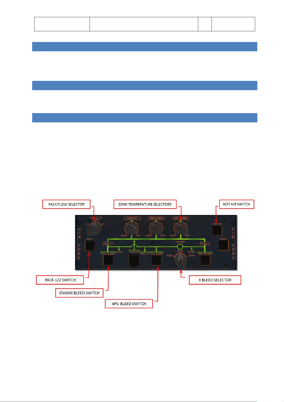
AIR CON D IT I ONING & PNEUMATICS
The air conditioning system is fully automatic and provides continuous renewal of conditioned air in three zones:
COCKPIT, FWD CABIN and AFT CABIN. Temperatures in these three zones can be regulated independently. The air
is supplied via the pneumatic systems using:
two pack flow control valves
two packs
the mixing unit that combines air from the packs and the cabin
The cold air from the PACKs is mixed with the hot bleed air (taken from the engines or APU) by a mixing unit that
is controlled by the zone regulator.
All control is done via the AIR COND panel on the overhead panel.
Zone temperature control selectors
o COLD = 18 °C
o CENTER = 24 °C
o HOT = 30° C
HOT AIR pb switch
o ON: hot air pressure is regulated
Page 6
Aerosoft
Airbus A320/A321
SYSTEMS
Systems guide
Vol
4
04-03-6
28 October 2014
o OFF: valve closes + trim air valve closes and cabin temperature will drop to external
temperature
o FAULT: (plus ECAM caution) when duct temperature is above 80°C, resets when temperature is
below 70°C
PACK pb switch
o ON: pack flow control is automatically controlled (note the pack flow valve is closed during
certain conditions like engine start etc.)
o OFF: pack flow control valves close
o FAULT: (plus ECAM caution) when valve position does not match the selected position
PACK FLOW
o LO: to be used with little or no passengers
o NORM: to be used with (near to) maximum amount of passengers
o HI: to be used to clear smoke or contaminants or in extreme temperatures (only available if
both engines are running)
ENG x BLEED pb
o ON
o OFF
o FAULT
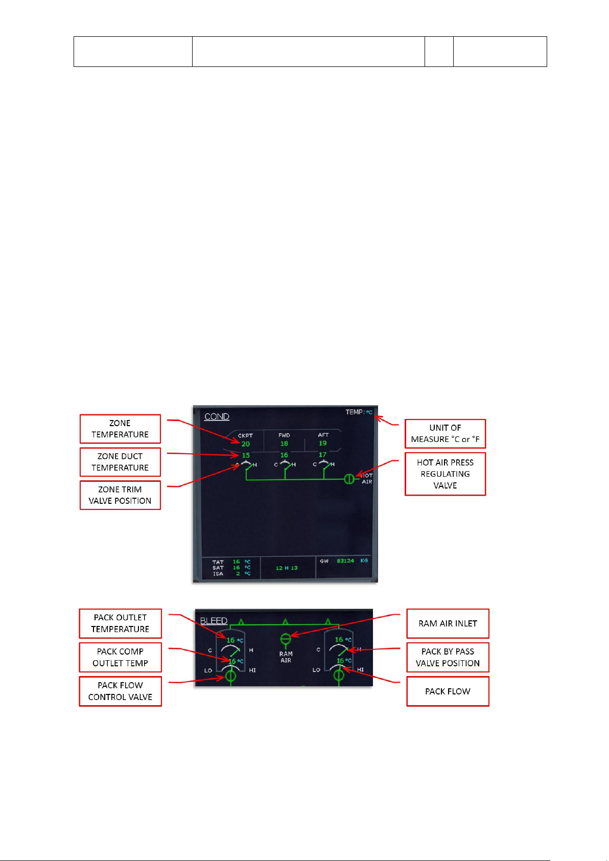
Feedback on the air conditioning system is given on the ECAM COND page and on the ECAM BLEED page.
Page 7
Aerosoft
Airbus A320/A321
SYSTEMS
Systems guide
Vol
4
04-03-7
28 October 2014
PRESS U R IZATION
Under normal operation conditions the complete pressurization is fully automatic. The system consists of:
two Cabin Pressure Controllers
outflow valve
control panel
two safety valves
In automatic operation pressurization is divided in 6 different modes
Ground: before take-off and 1 minute after landing the outflow valve is fully open to equalize pressure
with outside pressure.
Take-off: just before take-off the system prepresurizes the cabin to avoid a sudden pressure increase
Climb: cabin altitude is decreased to cruise level using input from vertical speed and other sensors
Cruise: cabin pressure is maintained
Descent: cabin altitude is increased to cruise level using input from vertical speed and other sensors
Abort: in case of an aborted take-off the system will prevent the triggered climb mode from starting to
decrease the pressure.
Page 8

Aerosoft
Airbus A320/A321
SYSTEMS
Systems guide
Vol
4
04-03-8
28 October 2014
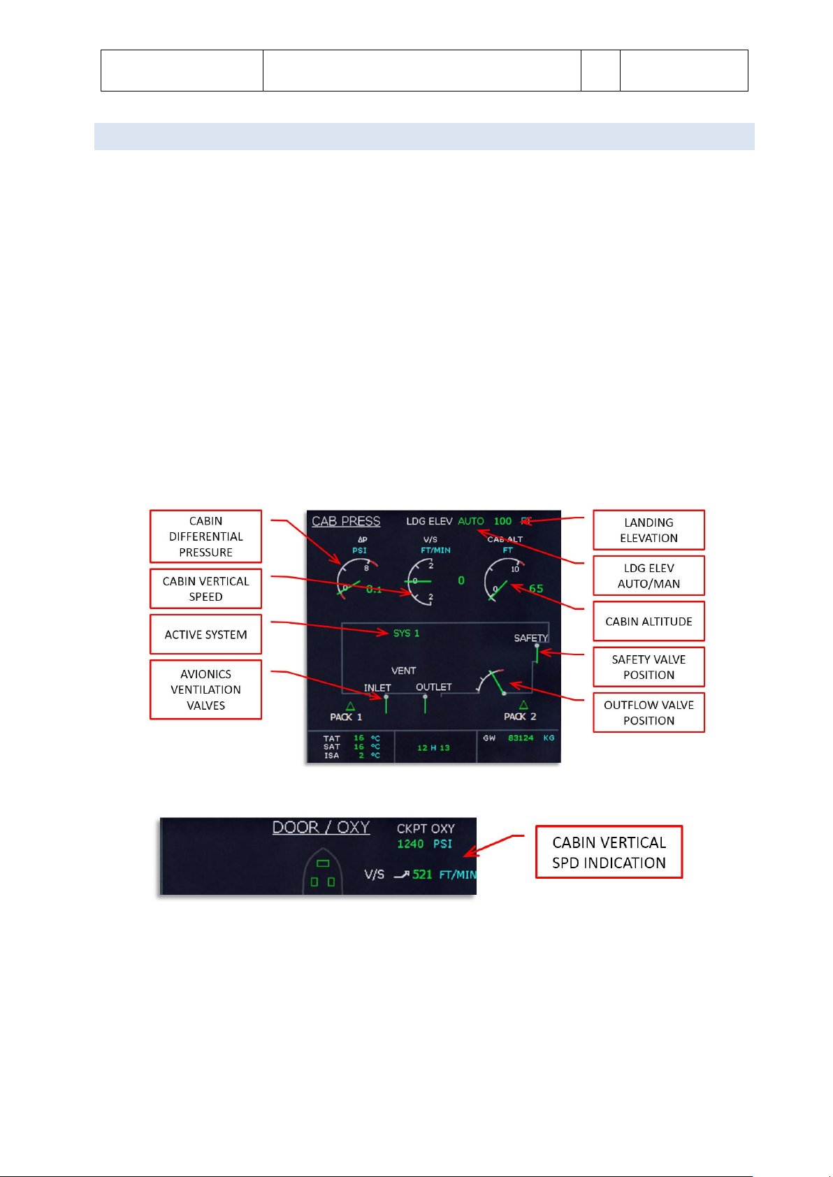
VEN T ILATION
The ventilation of avionics is controlled by the Avionics Equipment Ventilation Controller (AEVC). It provides
cooling of the avionics compartments using two fans, a heat exchanger that uses the outside skin of the aircraft to
cool the air and an inlet and outlet valve. Only the automated mode is simulated and you can see the ventilation
valve position on the CAB PRESS ECAM page. Battery, galley and toilet ventilation is provided by fans that draws
air from the cabin and vents it overboard via a vent in the aircraft skin.
Do note that the AEVC is very loud and other sounds from the aircraft systems that are heard on other aircraft
types are not heard on the Airbus A320 series.
APU
GENE R AL
The Auxiliary Power Unit provides:
Bleed air for engine starting
Bleed air for air conditioning
Electrical power for all the buses
The APU can be used on the ground and in flight with the following limitations:
100% generator load up to 25,000 feet
Full pneumatic and hydraulic pressure up to 20,000 feet
Can be started using the battery up to 25,000 feet.
SYS T E M COMPONENTS
The APU consists of a gas turbine engine with an APU computer that manages the system. The air intake uses a
electrically operated inlet flap and the exhaust vents in the tail cone. The electrical starter will start the engine
when the inlet flap is fully opened. The fuel is taken from the left wing tank using a separate fuel pump.
AIR B L EED SYSTEM
Bleed air from the APU is selectable from the overhead panel and has priority over main engine bleed air as long
as the APU BLEED pb is ON. The bleed air can start engines and provide the air condition system.
CONT R O L S AND DISPLAYS
The APU ECAM page displays the parameters of the APU. For the gas turbine engine N (in %) and EGT (in °C) are
available. The APU generator shows load (in %), voltage (in V) and frequency (in HZ) plus the connection to the
bus (arrow when connected, nothing when not connected). Bleed air shows pressure (in PSI) plus the position of
the valve (open or closed). All system messages are shown in green while within correct parameters, or amber
when outside correct parameters.
The APU MASTER SW pb on the overhead APU panel is pressed (ON will show) to power up the APU computer,
the fuel pump is activated and the air inlet is opened. When ON is shown the APU is ready to start.
The APU START pb starts the APU. When pressed it will show ON and the APU computer will command and
control the startup. Aircraft batteries must be selected ON, even when the engine generators are online. When
Page 9
Aerosoft
Airbus A320/A321
SYSTEMS
Systems guide
Vol
4
04-03-9
28 October 2014
FACs
FMGCs
FMS
FLIGHT MANAGEMENT
FLIGHT GUIDANCE
FLIGHT AUGMENTATION
the APU is running and bleed air and electrical power are available a green AVAIL will show and the ON will not be
shown. Note the APU needs a 3 minute cool down period after it has shut down.
On the ELEC panel the APU GEN pb will be dark when the APU generator is ON, and when pressed it will show OFF
as the APU generator is taken of line. When there is any problem an amber FAULT will show and the ECAM will
show more information.
On the AIR COND panel the APU BLEED pb will show ON when APU N speed is sufficient. When pushed the pb
will be dark and the bleed air valve will close. When there is any problem an amber FAULT will show and the
ECAM will show more information.
AUTOF L I G H T
OVE R V IEW
The following components are used by the pilot to interact with the autoflight system:
Flight Control Unit (FCU)
Multifunction Control and Display Units (MCDUs)
Sidesticks
Thrust levers
Primary Flight Display (PFD)
Navigation Display (ND)
The autoflight system is part of the Flight Management System (FMS). The FMS (including autopilots and
autothrust system) is made up by two Flight Management Guidance Computers (FMGCs) and two Flight
Augmentation Computers (FACs).
Flight Management provides navigation, performance optimization and display management.
Flight Guidance provides autopilot commands (sent to the flight control computers), flight director
commands (sent to the PFD) and thrust commands (sent to the autothrust systems).
Flight Augmentation provides flight envelope calculations, turn coordination and yaw damping.
PILOT I NTERFACES
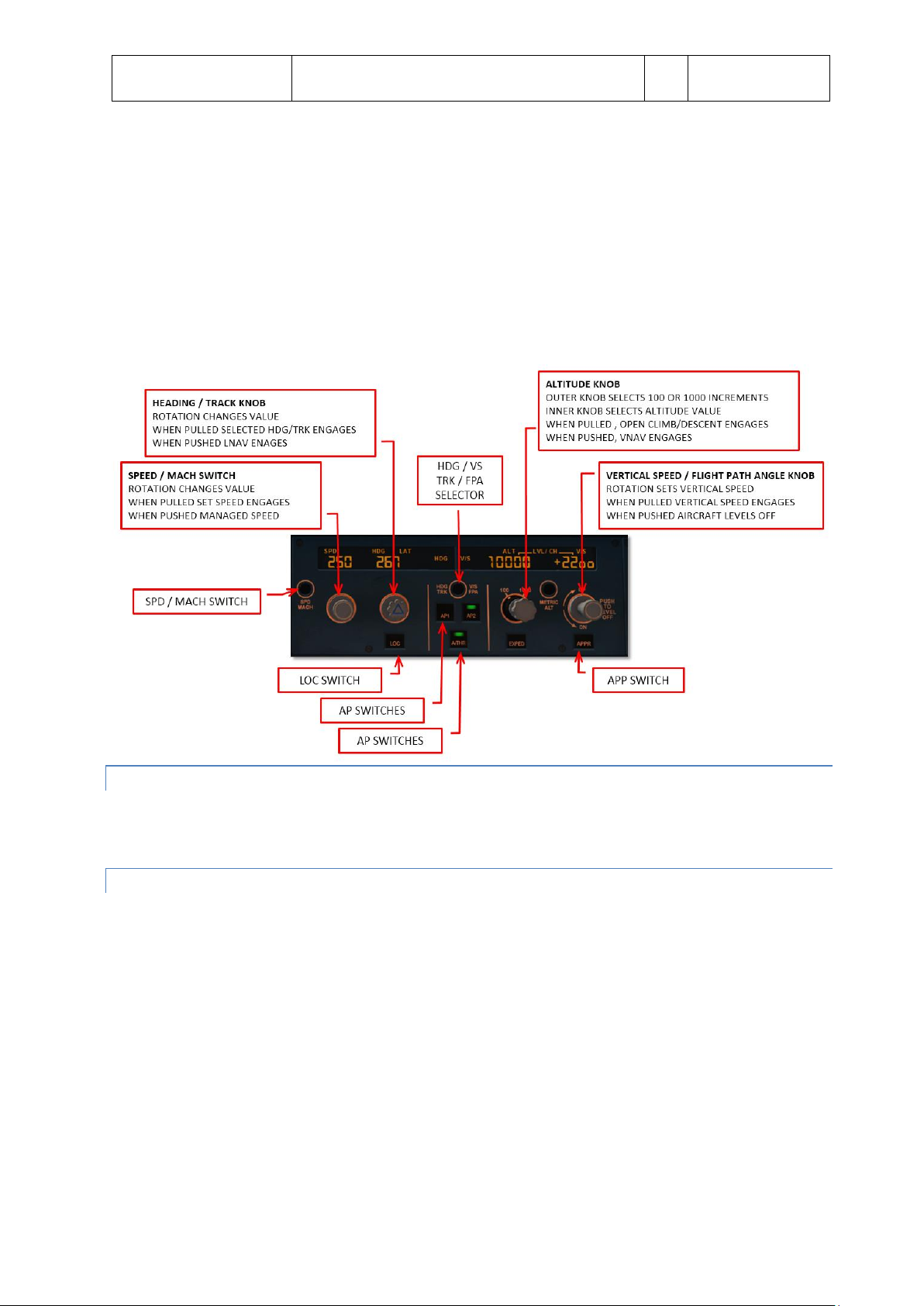
FLIG H T CONTROL UNIT
The FCU is located in the center of the glareshield and four knobs provide control for:
Airspeed
Heading (or track) or navigation modes
Climb or descent modes and/or
Vertical speed (or flight path angle)
Page 10
Aerosoft
Airbus A320/A321
SYSTEMS
Systems guide
Vol
4
04-03-10
28 October 2014
There are two modes possible for airspeed, heading and vertical speed. Switching between modes is done by
pulling (right click) the knob.
Selected Functions
o In selected mode the pilot controls speed and lateral/vertical navigation. After pulling the knob
the pilot can rotate the knob to set the desired value. When the knob is pushed (left click) the
current value for that function is inserted.
Managed Functions
o In managed mode the displays are dashed (note the FCU altitude windows is never dashed) and
the control of speed and lateral/vertical navigation is managed by the FMS.
MULTIF U NCTION CONTROL AND DISPLAY UN I T
The MCDUs is the primary interface between pilot and FMS (and in our simulation it is also used to access some
simulation functions.
SID E S T ICK CONTROLLER
The sidestick controllers are used to fly the aircraft manually. Any strong input with these will deactivate the
autopilot.
Page 11
Aerosoft
Airbus A320/A321
SYSTEMS
Systems guide
Vol
4
04-03-11
28 October 2014
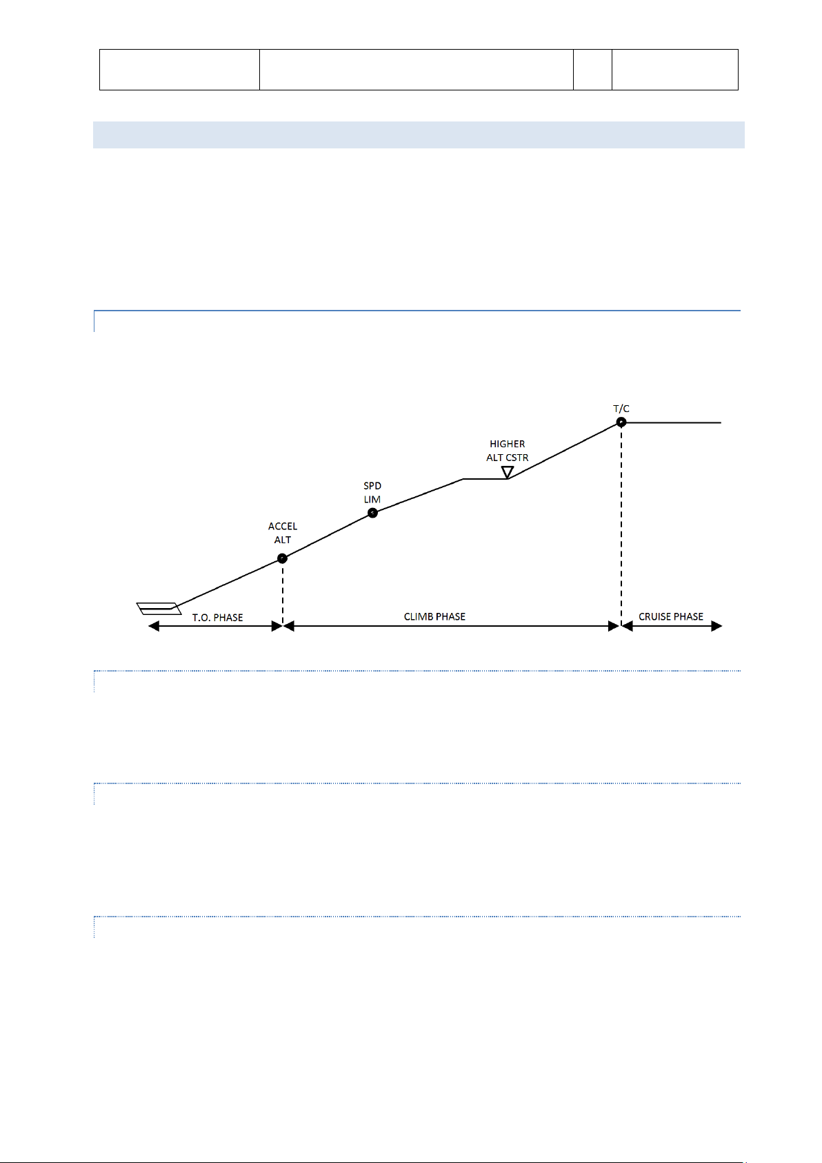
Flight Phase
Optimum Speed Profile
Switching conditions to next phase
Preflight
-
SRS take off mode engaged +
N1 > 85% or Ground Speed > 90 kts
Take Off
V2 followed by V2 +10
At ACC ALT (or manually)
Climb
ECON CLB SPD/MACH
At reaching Cruise Flight Level
Cruise
ECON CRZ MACH
At reaching ToD
Descent
ECON DES MACH/SPD
Overflying Decel waypoint with NAV (or LOC/LOC*) engaged
Manually activating APPR phase
Approach
VAPP (GS Min)
To Go Around: thrust levers to TOGA
To Done: automatic 30 seconds after landing
To Climb: inserting new CRZ FL
Go Around
VAPP or Current Speed
To Approach: manually select APPR phase
To Climb: manually select CLMB phase
Done
At depressing INIT or PERF to Preflight
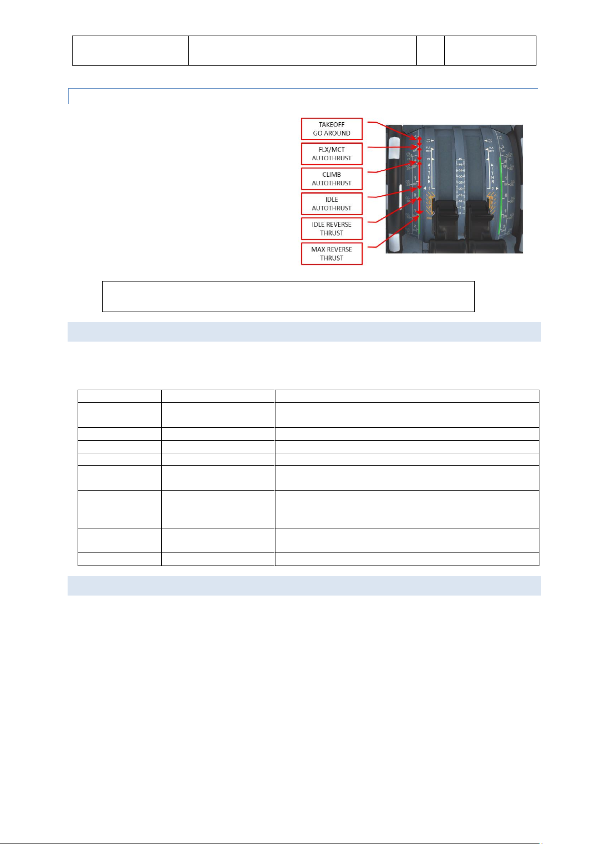
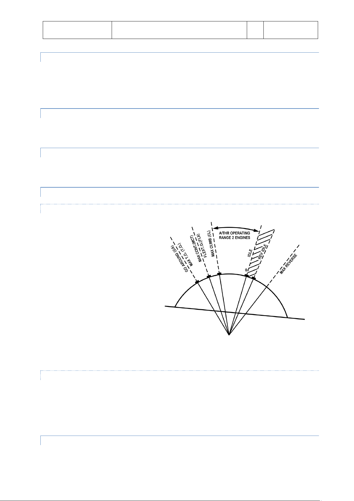
THR U S T LEVERS
The thrust levers are used to manually control thrust
or to select the desired autothrust mode. With both
engines operating the autothrust range is between
the idle and the FLX/MCT detents. With autothrust
active the position of the thrust lever determines the
maximum thrust level.
Normally the thrust levers are positioned in the climb (CL) detent at the thrust reduction
altitude after takeoff and left there until the landing flare.
FLIG H T PHASES
The FMGC divides the complete flight into phases that normally will automatically switch to the next phase when
certain conditions are met.
PERFO R M A NCE
The FMGC will minimize the flight cost through speed optimization. Depending on the Cost Index setting it will
compute optimal targets for the following items:
Take off, approach and go around speed are calculated as a function of the TOW and performance
model. Note that V1, V2 and Vr have to be manually entered (in our aircraft these speeds are calculated
but can be overwritten.
CLB and DES speeds are computed as a function of the GW, Cost Index, environment (temperature,
wind) and Cruise level. The speeds are NOT recalculated when the mode is active.
Cruise Mach is computed as the optimal speed and is updated continuously update to the current
weather condition and F-PLN modifications.
Optimum Flight Level is calculated assuming a 5 minute minimum cruise flight. It is continuously update
in flight.
Page 12

Aerosoft
Airbus A320/A321
SYSTEMS
Systems guide
Vol
4
04-03-12
28 October 2014
AUT O P I L O TS
ENG A GEMENT
The autopilot (two identical systems) are engaged by the AP1 and AP2 pb on the FCU. When engaged a green bar
will show on the pb and the appropriate FMA annunciation is displayed. When a flight director is on when the
autopilot is engaged, the autopilot engages in appropriate mode (OP CLMB and NAV) otherwise it will engage in
the default guidance modes (HDG and V/S or TRK-FPA).
Either autopilot can be engaged seconds after takeoff.
DISE N GAGEMENT
Disengage the autopilot by depressing the AP1 or AP1 button.
The autopilot is automatically disengaged by moving the side stick (or rudder pedals) a certain amount.
This will trigger a master warning.
The autopilot is automatically disengaged when the throttles are set above FLX/MCT on ground.
The autopilot is automatically disengaged when a normal law is exceeded or pitch or bank angle are
excessive.
The autopilot is automatically disengaged during a non-precision approach when the aircraft reaches
MDA minus 50 feet .
AUT O P I L O T & SPEED BRAKES
With the autopilot engaged the speed brakes are limited to ½ deflection. When autopilot is engaged with speed
brakes extended beyond ½ they will retract to ½. Note this will cause a sudden pitch up.
AUT O T HRUST
The autothrust system reduces workload for the pilot, provides additional comfort for the passengers and
reduces fuel use. Two main modes are included:
Fixed Thrust Modes
o Uses constant thrust; airspeed is controlled with pitch. Normally used for level changes when no
specific vertical speed is required.
Variable Thrust Modes
o In variable thrust mode the airspeed remains constant by changing the amount of thrust.
Normally used for level flight or when a certain airspeed is required during level change.
Page 13
Aerosoft
Airbus A320/A321
SYSTEMS
Systems guide
Vol
4
04-03-13
28 October 2014
AUT O T HRUST ARMING STATUS
When autothrust is OFF the thrust is controlled manually and corresponds to the position of the trust levers.
When autothrust is ARMED and the thrust levers are moved into the A/THR active the autothrust status changes
to ACTIVE. The status is shown on the FMA (blue indicates armed mode and white indicates active mode).
Autothrust is automatically armed during takeoff when thrust levers are in the TOGA or FLX detent.
AUT O T HRUST ACTIVE STATUS
The autothrust system controls thrust only in active status. Both fixed (MCT, CLB, IDLE, THR) and variable thrust
(SPEED, MACH) modes are available in active status.
AUT O T HRUST DEACTIVATION
The autothrust system can be disabled by depressing the FCU A/THR pb or by retarding the throttles to the idle
detent. A single chime and a short amber master caution illumination alerts the pilot.
AUT O T HRUST MODES
FIXED THRUST MODES
TOGO: Provides fixed maximum
thrust and is only available when
autothrust status is armed.
FLX: Flex thrust is used for reduced
thrust takeoffs. Thrust is
calculated using the assumed
temperature as set in the MCDU.
MCT: Provides Maximum
Continuous Thrust at the current
ambient conditions.
CLB: Provides fixed thrust equal to
the climb thrust rating at current
ambient conditions.
IDLE: Provides fixed idle thrust.
Only available in active autothrust status. Note the thrust levers can be anywhere in the autothrust
range!
THR: When the thrust is not TOGA, FLX, MCT or CLB the fixed thrust is called THR.
VARIABLE THRUST MODE S
SPEED: The autothrust system will provide variable thrust to maintain a set speed or a managed speed in
level flight or when the aircraft follows a programmed flight path. Only available when autothrust is
active.
MACH: Identical to speed mode but not available at low altitudes. The speed mode is automatically
switched to Mach mode (and vice versa) at a preset altitude.
AUT O T HRUST/FLIGHT DIRECTOR/AUTOPILOT
The vertical guidance modes use pitch to maintain a target speed or a specific vertical path. If vertical guidance
modes are used to control a target speed, autothrust uses a fixed thrust mode. If vertical guidance modes are
Page 14

Aerosoft
Airbus A320/A321
SYSTEMS
Systems guide
Vol
4
04-03-14
28 October 2014
used to control a specific vertical path, autothrust uses variable thrust to maintain target speed. When manually
flown in fixed autothrust mode the flight director’s pitch command bar indicates the pitch needed to fly the
desired speed.
ALPHA FLOOR
The alpha floor protection assists the pilot in recovering from dangerous low speed and high angle of attack by
automatically setting TOGA thrust when:
Excessive angle of attack (alpha)
Excessive high nose up attitude
Windshear is detected
When the alpha floor conditions are no longer detected the autothrust system will stay in TOGA lock until the
pilot disables auto throttle. It is recommended the pilot moves the throttle to the TOGA detent before depressing
the FCU A/THR pb to avoid a power surge. After that the pilot can pull the throttle to the CL indent and engage
the autothrust.
FLIG H T AUGMENTATION COMPUTERS
The FACs handle:
Yaw damping and turn coordination
Rudder trim
Flight envelope and maneuvering speed computations
Alpha floor protection
Windshear detection
Low energy detection
FLIG H T ENVELOPE
Many different speeds are calculated by the FACs are used by the autoflight system. These speeds include the
minimum safe speed, maximum speed and never exceed speed. They also calculate the alpha floor speed. Most
of these speeds are shown on the PFD airspeed indicator.
WIN D S HEAR
The FACs will try to detect windshear and will warn the pilot of this dangerous condition. Windshear detection is
only active below 1300 feet AGL in configuration 1 or greater. When detected the flight director will show an
optimal pitch attitude and the aural warning “WINDSHEAR” will be heard.
LOW EN E R GY WARNING
Between 2000 and 100 feet AGL the FACs will detect a low energy state (based on airspeed, descent angle and
angle of attack) and will warn the pilot with an aural “SPEED SPEED SPEED” warning. Normally this warning will
precede an alpha floor condition.
FLIG H T GUIDANCE
Page 15

Aerosoft
Airbus A320/A321
SYSTEMS
Systems guide
Vol
4
04-03-15
28 October 2014
Flight guidance is provided for speed control, lateral navigation and (limited in this project) vertical navigation.
There are two types:
Selected Guidance: In this mode the aircraft will fly on autopilot using the settings on the FCU. You
switch from managed mode to selected mode by pulling (right mouse click) the SPD, HDG and ALT knobs.
Managed Guidance: In this mode the airspeed is calculated by the FMS and differs per flight phase. The
FMS also provides managed lateral and vertical flight plan guidance following the flight plan that has
been inserted in the MCDU. The FCU will show dashes in managed guidance. You switch from selected
guidance to managed mode by pushing (left mouse click) the SPD, HDG or ALT knobs.
Please note the FCU altitude window will never be dashed.
When the autopilot is engaged or the flight director is activated the Flight Mode Annunciator (FMA) (at the
top of the PFD) will also display the activated settings.
LATE R A L GUIDANCE MODES
The lateral guidance modes keep the aircraft course to its destination.
SEL E C T E D HEADING (OR TRACK) MODE
The heading (or track) mode will guide the aircraft on a heading (HDG) or track (TRK) and is the default lateral
mode. The pilot activates it by pulling (right mouse click) the HDG button on the FCU. A digital display of the
heading (track) will be shown on the FCU and HDG will be displayed on the FMA. Note this mode cannot be
activated when LAND mode is activated.
If the knob is turned to the desired HDG (TRK) and pulled the aircraft will make the shortest turn to the
selected HDG (TRK)
If the HDG knob is pulled but not turned the current HDG (TRK) is selected.
If the HDG knob is pulled first and turned the aircraft will turn in the direction of the turn.
If the HDG knob is turned but not pulled the selected value is cleared after a period that depends on the
flight mode.
MANA GED NAVIGATION MODE
When a flight plan is available and activated the managed nav mode will guide the aircraft along the path stored
in the FMS. It is activated by the pilot by pushing (left mouse click) the FCU HDG knob. The display will show
dashes and the FMA will display NAV.
LOCAL I Z ER LATERAL MODE
When the FCU LOC pb is pushed the loc lateral guidance mode is armed and the FGS will only use the localizer
signal for lateral guidance. In the FMA LOC will be displayed and the LOC pb will illuminate. It can be used to
intercept and track a localizer while maintaining a selected altitude. Note that a ILS frequency must be tuned and
TAKEOFF and GO-AROUND mode are not selected. To disarm press the LOC pb again.
Page 16
Aerosoft
Airbus A320/A321
SYSTEMS
Systems guide
Vol
4
04-03-16
28 October 2014
VER T I C AL M ODES
The vertical guidance modes will make the aircraft change altitude. To leave a FCU selected altitude a dual action
sequence is needed:
Turn the ALT selector to set the new altitude
Pull the ALT selector to select OPEN CLB/DES mode or
Push the ALT selector to engage CLB/DES mode or
Select a target V/S and pull the V/S selector knob to engage V/S mode
CLIM B
CLB mode manages the vertical guidance towards the FCU selected altitude taking altitude and speed constraints
into account.
ARMING CONDITIONS
On ground or when TAKE OFF or GA modea are engaged as long as no other vertical modes are selected.
In flight when lateral NAV mode is engaged, FCU selected altitude is higher than aircraft altitude or when
aircraft meets a ALT CSTR
DISARMING CONDITIONS
Engagement of any other vertical mode
FCU selected mode lower then aircraft altitude
Switching to DES or APP phase
Loss of vertical flight path validity or loss of ANV mode
ENGAGEMENT CONDITION S
Aircraft more than 5 seconds in flight
FCU selected altitude above current altitude
Not in descent or approach mode
NAV mode engaged
Not in G/S mode
CLB mode is automatically selected when
Page 17

Aerosoft
Airbus A320/A321
SYSTEMS
Systems guide
Vol
4
04-03-17
28 October 2014
o ACC ALT is reached
o ALT CSTR is reached with CLB mode armed
CLB mode can be manually selected by pushing the ALT selector knob.
DISENGAGEMENT CONDIT IONS
NAV mode lost or disengaged
Selecting another vertical mode
Setting a lower altitude in FCU than current altitude
GUIDANCE
In standard CLB mode the engine stay at max climb thrust, the speed will be the one calculated by the FMGS and
pitch will vary to keep that speed.
OPEN C L I M B
ENGAGEMENT CONDITION S
The aircraft must be in flight more than 5 seconds
LAND mode is not engaged
FCU selected altitude is higher than current altitude
OPEN CLIMB is engaged by:
Pulling the ALT selector knob
Acceleration altitude reached with armed CLM mode and NAV not engaged
When an overspeed condition is detected (the aircraft will pitch up to loose speed)
DISENGAGEMENT CONDIT IONS
Selecting any other vertical mode
Selecting a lower altitude then the current altitude
GUIDANCE
In OPEN CLB the target Speed / Mach is kept by varying the pitch, thrust is managed by the A / THR or manually,
speed target can be selected or managed. All ALT CSTR are ignored in OPEN CLB.
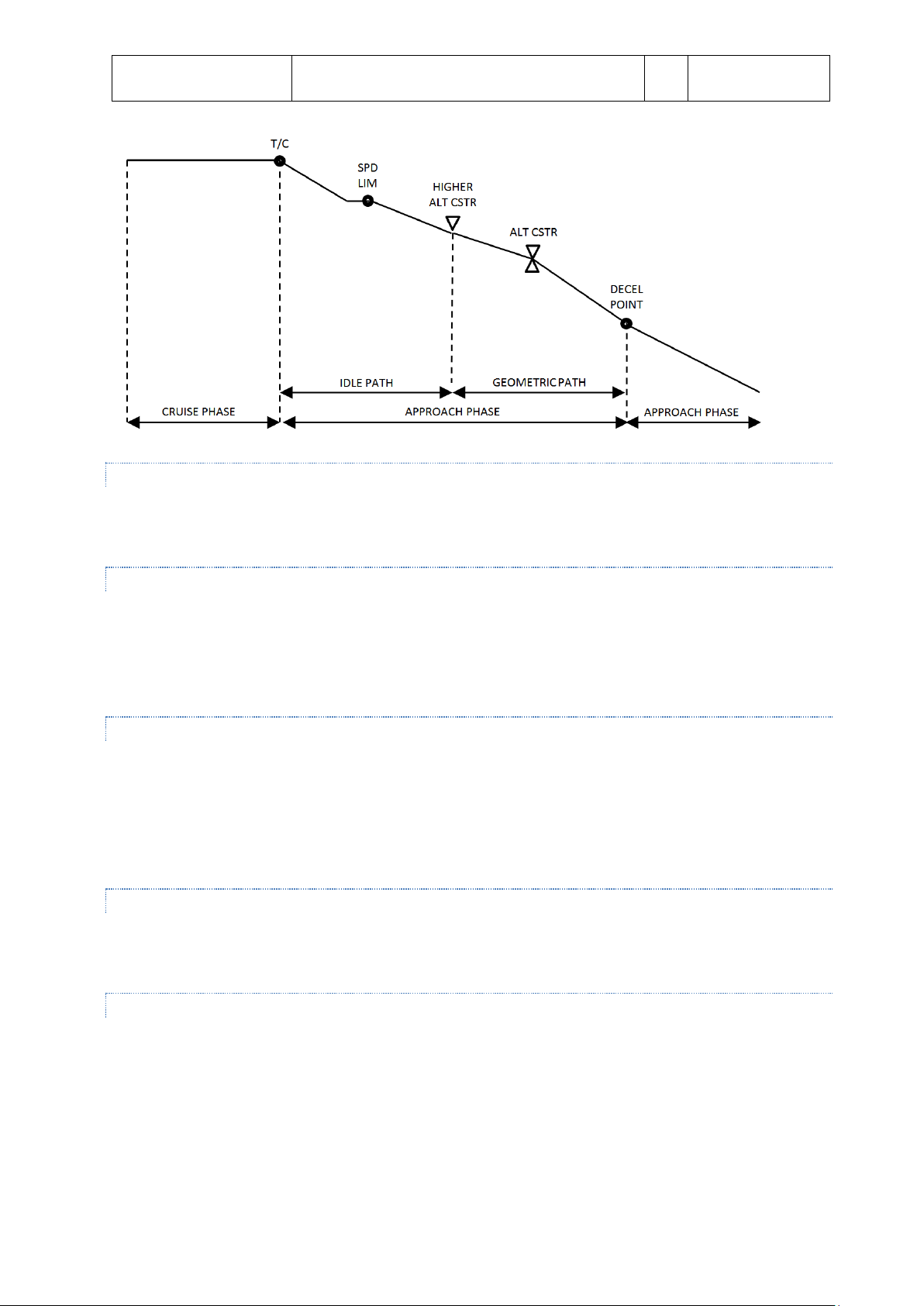
DESC E N T
DES mode provides vertical guidance following a computed descent profile between Top of Descent to the
Deceleration point. It uses the data in the F-PLN and the available WIND data. It is divided into three sections:
Repressurization segment (ignored in our simulation)
Idle Path segment where the engines are at idle and AP / FD controls SPD
Geometric path when the AP / FD controls vertical path and the A /THR controls the SPD
Page 18
Aerosoft
Airbus A320/A321
SYSTEMS
Systems guide
Vol
4
04-03-18
28 October 2014
ARMING CONDITIONS
FCU selected altitude is below current altitude
TAKE OFF, GO AROUND or LAND mode is not engaged
DISARMING CONDITIONS
Selecting any other vertical mode
FCU selected altitude is above current altitude
Loss of NAV, LOC or vertical path validity
Selecting GO AROUND mode
ENGAGEMENT CONDITION S
FCU selected level is below current altitude
NAV, LOC* or LOC is active
TAKE OFF, GO AROUND, LAND, FINAL not active
DES mode is engaged automatically when an altitude constraint is met with DES mode armed.
DES mode is manually engaged by pushing the ALT selector knob
DISENGAGEMENT CONDIT IONS
Engagement of any other vertical mode
Selecting a FCU altitude above current altitude
GUIDANCE
In DES mode the aircraft is guided along the DES PATH. The SPD target can be selected or managed (with the
speed to vary around the calculated optimal nominal descent speed. SPD CSTR is taken into account in the speed
profile.
If the aircraft is above the DES PATH it will pitch down until the upper limit of the MANAGED SPD RANGE is
reached. That speed will be kept and the aircraft will differentiate from the DES PATH. Extending ½ speed brakes
will allow the aircraft to get back on the calculated path.
If the aircraft is below the DES PATH the aircraft will maintain the target speed until the DES PATH is reached.
Page 19
Aerosoft
Airbus A320/A321
SYSTEMS
Systems guide
Vol
4
04-03-19
28 October 2014
OPEN D E S CENT
In selected descend mode the autothrust system will be set to idle and the set speed will be kept using pitch. This
mode is not useful for final approaches.
ENGAGEMENT CONDITION S
The aircraft must be in flight more than 5 seconds
LAND mode is not engaged
FCU selected altitude is lower than current altitude
OPEN DESCENT is engaged by pulling the ALT selector knob
DISENGAGEMENT CONDIT IONS
Selecting any other vertical mode
Selecting a higher altitude then the current altitude
GUIDANCE
In OPEN DES the target Speed / Mach is maintained by pitch controls and thrust is maintained by the A / THR or
manually by the pilot. Speed target can be selected or managed.
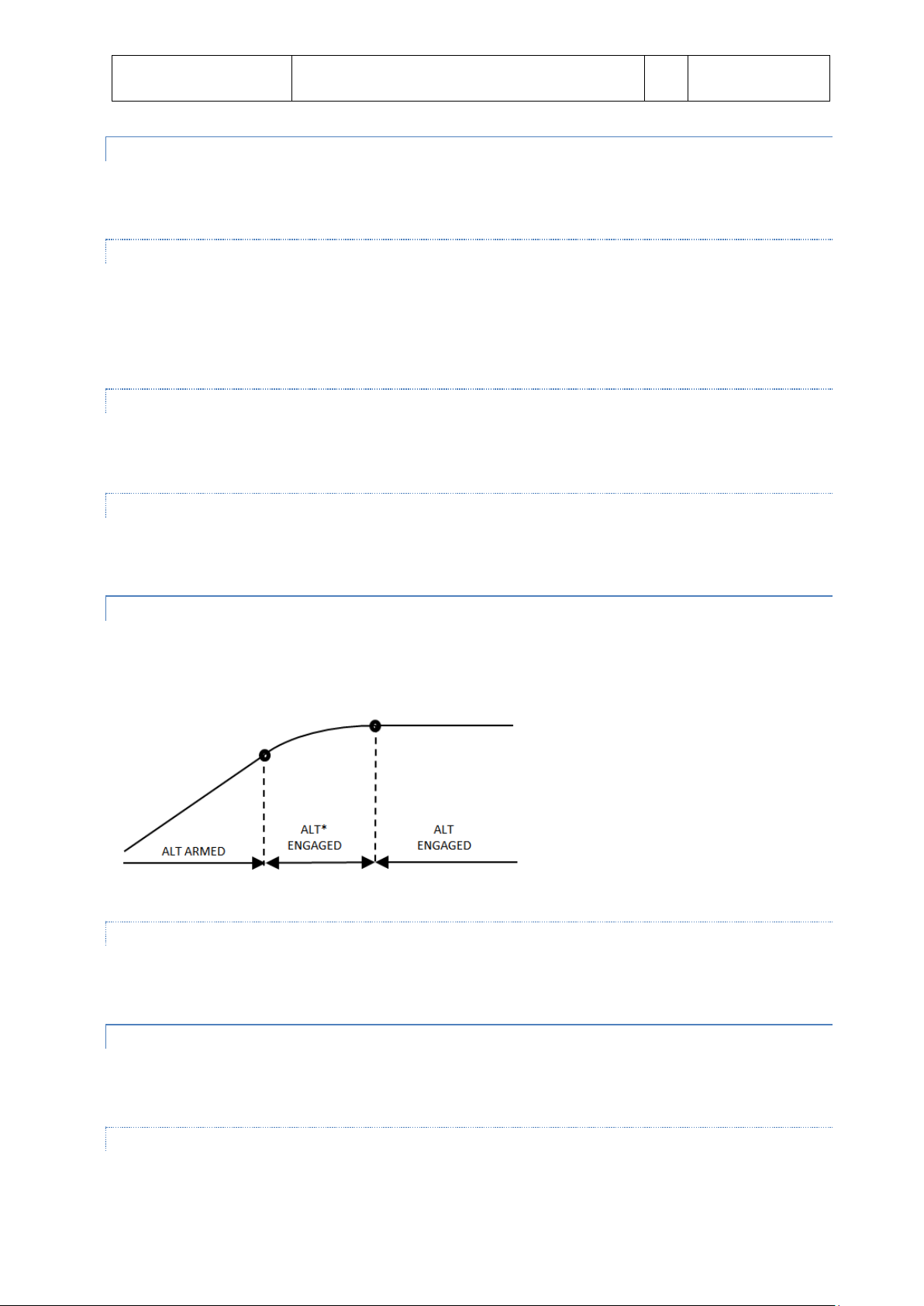
ALTI T U D E ACQUIRE
ALT* will guide the aircraft to the FCU selected altitude, ALT CST* guides the aircraft to an altitude constraint.
Once the set altitude is reached the ALTITUDE HOLD (ALT or ALT CST) mode will engage.
GUIDANCE
In the ALT* and ALT CST* mode the vertical speed is managed to reduce vertical speed to ensure a smooth
capture of the set FCU altitude.
ALTI T U D E HOLD
ALT mode will keep the aircraft at a set altitude. The altitude can be a FCU set altitude (with ALT engaged) or an
altitude constraint.
ARMING CONDITIONS
ALT mode is automatically armed when the aircraft climbs or descents to a target altitude.
Page 20

Aerosoft
Airbus A320/A321
SYSTEMS
Systems guide
Vol
4
04-03-20
28 October 2014
ENGAGEMENT CONDITION S
ALT or ALT CST is automatically engaged when the aircraft is 20 feet from the target altitude.
DISENGAGEMENT CONDIT IONS
ALT or ALT CST is disengaged when any other vertical mode is selected.
GUIDANCE
The level kept is the level memorized at engagement of the mode.
VER T I C AL SPEED – FLIGHT PATH ANG L E
V/S–FPA is a selected mode, it captures and keeps the vertical speed or the flight path displayed in the V/S – FPA
FCU window.
ENGAGEMENT CONDITION S
V/S-FPA is automatically selected:
5 seconds after liftoff with no other vertical mode selected
Loss of G/S, G/S*, FINAL, LOC. LOC*, NAV (with DES engaged)
Automatic reversions
V/S-FPA is manually selected by:
V/S-FPA selection knob pulled
V/S-FPA selection knob pushed (will engage an immediate level off and set VS=0)
AP engagement with no other vertical mode set
Selection of an different altitude (at least 250 ft from current altitude) in ALT*
Selection of an higher altitude in DES or OP DES
Selection of an lower altitude in CLB or OP CLB
DISENGAGEMENT CONDIT IONS
Engagement of other vertical mode
o Manually by pulling altitude selection knob or performing a go around
o Automatically by reaching FCU altitude or G/S* engagement
GUIDANCE
FMGS pitch mode will guide the aircraft to the target V/S (FPA). A/THR mode is SPD or MACH.
V/S-FPA guidance has priority over speed guidance and when reaching the limit of the flight envelope will change
to OPEN mode.
Page 21

Aerosoft
Airbus A320/A321
SYSTEMS
Systems guide
Vol
4
04-03-21
28 October 2014
COMMON MODE
VERTICAL
LATERAL
TAKE OFF
Mode: Pitch Take off
FMA: SRS
Mode: Runway LOC or Runway Track
FMA: RWY or RWY TRK
ILS APPROACH
Mode: G/S* or G/S
FMA: LAND or FLARE or ROLL OUT
Mode: LOC* or LOC
FMA: LAND or FLARE or ROLL OUT
NON ILS APPROACH
Mode: Final Descent
FMA: FINAL
Mode: Nav
FMA: APP NAV
GO AROUND
Mode: Pitch Go Around
FMA: SRS
Mode: Go Around track
FMA: GA TRACK
COMMON M O D ES
COMMON modes are combinations of vertical and lateral modes.
TAK E O FF : SRS
This mode is available during take off and the first 5 seconds of flight. In SRS mode the aircraft will follow pitch
guidance at speeds defines by the speed reference guidance law.
ENGAGEMENT CONDITION S
V
is inserted in MCDU
2
Slats are extended
DISENGAGEMENT CONDIT IONS
Manually by engaging any other vertical mode
Automatically at acceleration altitude
GUIDANCE
The aircraft will keep V
An attitude protection will prevent a too high nose up during take off
Flight path angle of minimum climb rate of 120 ft/min
+ 10 knots
2
TAK E O FF: RUNWAY
The RUNWAY mode will provide lateral guidance during take off and immediately thereafter using the LOC signal
(when it is available. The RUNWAY TRK mode will provide lateral guidance on an extended runway center line.
ENGAGEMENT CONDITION S
SRS engagement conditions
LOC signal received
Aircraft heading within 20 degrees of runway heading
Page 22

Aerosoft
Airbus A320/A321
SYSTEMS
Systems guide
Vol
4
04-03-22
28 October 2014
DISENGAGEMENT CONDIT ION
Loss of LOC signal
Any other lateral mode selected
GUIDANCE
The RWY mode will guide the aircraft as close as possible to the center runway line and on an extended runway
line in flight in the RWY TRK mode.
APPRO A C H: ILS APPROACH
ARMING CONDITIONS
Aircraft over 400 ft AGL
ILS approach is selected
ILS and RA are available
GA or FINAL mode not selected
DISARMING CONDITIONS
Depressing the APPR pb (both LOC and G/S mode will disarm)
Depressing the LOC pb (only G/S will disarm)
Go AROUND mode selected
Disengaging AP
ENGAGEMENT CONDITION S
Radio Altimeter active
LOC* and G/S* mode engage
DISENGAGEMENT CONDIT IONS
Depressing the APPR pb (both LOC and G/S mode will disarm)
Depressing the LOC pb (only G/S will disarm)
Pull action on the V/S/FPA button
Pull action on the HDG/TRK button
Go AROUND mode selected
Page 23

Aerosoft
Airbus A320/A321
SYSTEMS
Systems guide
Vol
4
04-03-23
28 October 2014
LAND MODE
LAND mode engages automatically when the LOC and G/S modes are engaged and aircraft is below 400 AGL.
FLARE MODE
At 40 ft RA the FLARE mode automatically engages. At 30 ft AGL the aircraft will align with the runway, will pitch
up and when A/THR is active the trust reduction (RETARD) will activate.
ROLL OUT MODE
When load is detected on the main gear the ROLL OUT mode will automatically be activated and centerline
guidance is provided.
SPEED CONTROL
A/THR will provide speed control during and ILS approach when speed can be managed or selected.
APPRO A C H: NON ILS APPROACH
ARMING CONDITIONS
Aircraft over 400 ft AGL
NON ILS approach is selected
GA or FINAL mode not selected
DISARMING CONDITIONS
Depressing the APPR pb (both LOC and G/S mode will disarm)
Depressing the LOC pbn (only G/S will disarm)
Go AROUND mode selected
Disengaging AP
ENGAGEMENT CONDITION S
Radio Altimeter active
APP phase is active
APP NAV mode engaged
FINAL is armed
DISENGAGEMENT CONDIT IONS
Page 24

Aerosoft
Airbus A320/A321
SYSTEMS
Systems guide
Vol
4
04-03-24
28 October 2014
Depressing the APPR pb
Depressing the LOC pb
Automatically at MDA (MDH)
Go AROUND mode selected
GUIDANCE
The aircraft is guide down to MDA/MDH where AP is automatically disconnected.
GO AR O U ND
This mode is a combination of the SRS vertical and the GA TRK lateral mode.
ENGAGEMENT CONDITION S
Thrust levers in TOGA detent will engage SRS/GA TRK as long as slats/flaps lever is in position 1 and the aircraft is
in flight.
DISENGAGEMENT CONDIT IONS
Manually engaging another mode
Automatically at GA ACC ALT
GUIDANCE
SRS is similar to SRS take off. Speed will be kept on speed on engagement or V
the aircraft along the track the aircraft was at engagement.
if that is higher. GA TRK guides
APP
Page 25

Aerosoft
Airbus A320/A321
SYSTEMS
Systems guide
Vol
4
04-03-25
28 October 2014
MANA GES MODE VERSUS SELECTED MODE
In Managed modes the Flight Management Guidance Computer sends information to the Autopilot systems so
that it follows the programmed route. This route can include headings, altitudes and even speeds. The pilot
selects this mode by pushing (left click) the appropriate selector knob on the Flight Control Unit (FCU).
In Selected modes the pilot inserts the information and the aircraft will follow his manual input. The pilot selects
this mode by pulling (right click) the appropriate selector knob on the Flight Control Unit and turning it the
required setting.
MANA GED SPEED
On PFD the Target Airspeed shows in magenta
On the FCU the Speed/Mach will show dashes and a white dot
On the MCDU (PERF page) Managed mode is displayed with the target value
SEL E C T E D SPEED
On PFD the Target Airspeed shows in blue
On the FCU the Speed/Mach will display the Target Airspeed
Page 26

Aerosoft
Airbus A320/A321
SYSTEMS
Systems guide
Vol
4
04-03-26
28 October 2014
MANA GED LATERAL GUIDANCE
On the PFD the FMA will display NAV
On the FCU the Heading/Track window will show dashes and a white dot
On the PFD/ND the actual (not selected) heading and actual track is displayed
On the ND the flight plan track is displayed as a continuous green line
SEL E C T E D L ATERAL GUIDANCE HEAD I NG O R T R A CK
On the PFD the FMA will display HDG (or TRK)
On the PFD/ND the selected heading or Track Index (blue)
On the ND the flight plan track is displayed as a dashed green line and the actual track by a continuous
green line
On the FCU the Heading/Track window will show the Target Heading (Track)
(NOTE: In HDG, if in a climb or descent, VNAV will change to OP CLB or OP DES. To reselect NAV and managed
CLB/DES, push HDG FCU knob in [left click], then push in [left click] the FCU ALT knob)
Page 27

Aerosoft
Airbus A320/A321
SYSTEMS
Systems guide
Vol
4
04-03-27
28 October 2014
MANA GED CLIMB
On the PFD the FMA will display a green CLB, with a blue ALT beneath it
On the FCU the altitude will show the dialed value with a white dot to the right of it
On the MCDU (PERF page) will be displayed as the CLB page
OPEN C L IMB
To activate OP CLB, pull (right click) the FCU ALT knob after dialing in a higher altitude. In OP CLB, the
FMGS will disregard any altitude constraints and climb straight to the altitude in the FCU.
On the PFD the FMA will show OP CLB
On the FCU the selected altitude will show without a white dot next to it
Page 28

Aerosoft
Airbus A320/A321
SYSTEMS
Systems guide
Vol
4
04-03-28
28 October 2014
SEL E CTED C L I M B
For selected V/S climb, pull (right click) the FCU V/S knob.
On the PFD the FMA will show in green VS and in blue the selected vertical speed, with a blue ALT
beneath it.
On the FCU you will read the selected V/S with a + sign to the left of it, and the dialed altitude without a
white dot to the right of it.
MANA GED DESCENT
On the PFD the FMA will display a green DES, with a blue ALT beneath it
On the FCU the altitude will show the dialed value with a white dot to the right of it
On the MCDU (PERF page) will be displayed as the DES page
Page 29

Aerosoft
Airbus A320/A321
SYSTEMS
Systems guide
Vol
4
04-03-29
28 October 2014
OPEN D E S CENT
To activate OP DES pull (right click) the FCU ALT knob after dialing in a lower altitude. OP DES acts similar
to OP CLB, in that it will descend in an idle descent to the altitude dialed in the FCU disregarding any
altitude constraints.
On the PFD the FMA will show OP DES
On the FCU the selected altitude will show without a white dot next to it
SEL E C T E D D E SCENT
For selected V/S descent, pull (right click) the FCU V/S knob.
On the PFD the FMA will show in green VS and in blue the selected vertical speed with a – sign in
between, and a blue ALT beneath it
On the FCU you will show the selected V/S with a – sign to the left of it, and the dialed altitude without a
white dot to the right of it
Page 30

Aerosoft
Airbus A320/A321
SYSTEMS
Systems guide
Vol
4
04-03-30
28 October 2014
VER T I C AL GUIDANCE LEVEL OFF
To immediately level off, push (left click) the FCU V/S knob.
On the PFD the FMA will show in green VS and in blue 0, with a blue ALT beneath it.
On the FCU you will read the selected V/S of 00oo, and the dialed altitude will remain at the altitude
dialed previously, without a white dot to the right of it
Page 31

Aerosoft
Airbus A320/A321
SYSTEMS
Systems guide
Vol
4
04-03-31
28 October 2014
COMM UNICATIONS
Unfortunately FSX is not very strong with radios and we really wanted to stick to the default commands of FSX
because a lot of people have hardware for these parts. So we went for practicality more than for getting the
simulation exactly as the real aircraft. It’s a small price to pay for compatibility and usability.
COMMUN ICATION RADIOS
Communication radios (VHF) are set using the Radio Management Panel on the pedestal while Navigation radios
are set on the MCDU system. The backup Radio navigation option on the RMP is not implemented. The
communication radios VHF1 and VHF2 (FSX calls that COMS 1 and COMS 2) are set on the Radio Management
Panel on the center console. VHF1 is set on the Captain side (left), VHF2 is set on the First Officer side (right).
1. ON / OFF sw: Toggles power to the panel
2. NAV key: Not implemented
3. STBY NAV keys: Not implemented
4. ROTATING KNOB: Outer wheel sets most significant digits, inner wheel sets least significant digits. When
a frequency has a COURSE attached to it the inner wheel sets the COURSE
5. TRANSFER KEY: When pressed the ACTIVE and STBY frequencies are interchanged.
6. STBY / CRS window: Shows STBY frequency or COURSE
7. ACTVIVE window: Shows the active frequency of the selected radio system
8. BFO key: Not implemented
Page 32

Aerosoft
Airbus A320/A321
SYSTEMS
Systems guide
Vol
4
04-03-32
28 October 2014
AUD I O M ANAGEMENT SYSTEM
The Audio Management System determines which sources you
will hear. With the button depressed the source is not heard,
with the button depressed and lit the corresponding source is
heard. Please note that FSX does not have a separate ILS receiver
and that is always linked to VOR 1.
DOO R S A N D WINDOWS
The external doors and cargo hatches can be opened using a simulated page in
the right MCD under the ACFT DOORS page. When the aircraft is stopped,
engines are off and the parking brakes (or chocks) are set, you can open the
doors via this menu. The door identifier will blink when the door is being
opened or closed. This menu is not available when the aircraft is not
stationary, with engines off and on parking brakes (or with wheel chocks
activated).
All external doors in the Airbus A32x are
conventional in design and operation and all door
operation can be monitored on the ECAM DOORS
page. The ECAM DOOR/OXY page will appear
automatically:
as the default ECAM system display page
with the engines shut down
when any door is not closed and an engine
is running.
It may also be selected by depressing the DOOR pb
on the ECAM panel.
During taxying it is allowed to open the
cockpit windows.
The cargo doors should never be open
with the right engine running. The
cockpit door should stay locked in flight
and a small video camera (with a display
mounted above the door) allows the
crew to see who is behind the door.
Page 33

Aerosoft
Airbus A320/A321
SYSTEMS
Systems guide
Vol
4
04-03-33
28 October 2014
The windshields consist of multi layered glass and are
electrically heated to prevent icing. Two of the windows
have sliding mechanisms. To open the windows left
mouse click on the handle. The window will be opened
by a rattle mechanism. To close the window, right mouse
click on the handle. Make sure the red ring underneath
the release button is shown to indicate the window is
locked. The status of the windows is also shown in the
ECAM DOORS page.
ELEC T R ICAL
GENE R AL
In normal operation the generation and distribution of electrical power is fully automated and does not need any
interaction. Even when there are failures the systems will almost always be able to correct or activate alternate
systems when needed. As with all overhead panels a dark panel with all lights off indicates systems without fault
and in automatic mode.
AC G E NERATION
AC power is distributed via the two AS buses. Each engine generator supplies one of the two buses but a tie
connection allows one of the generators to provide both buses. The APU generator can be used as the sole source
for all systems, excluding the galleys. Note that at high altitude the APU generator load capacity is decreased.
When available, Ground Power is able to provide all buses with electricity. The two batteries are connected to
the buses via a static converter. An automated bus tie system interconnects all systems.
AC B U SES
There are 5 buses for AC power:
1. AC1 Bus
2. AC2 Bus
3. AC ESS Bus
4. AC ESS SHED Bus
5. AC Ground/Flight (the latter is ignored)
DC GE N E RATION
The DC system powers the DC components, and is needed to start the APU when no EXT PWR is available. The DC
electrical system is the first backup for the AC system and will power essential components when all AC
generators are offline. In normal operation three transformer rectifiers (TRs) convert AC to DC and AC1 is the first
source for DC power.
Two NICAD batteries connect to their own hot battery bus that is always active. The batteries are charged using
the DC BAT bus and disconnected from all buses when they are not needed and fully charged. The batteries use
proprietary code so they will not lose power as fast as standard FSX batteries. Depending on your use you should
be able to run the systems on battery for up to half an hour. Of course it is advised to either connect external
power of power up the APU to avoid your aircraft going cold and dead unexpected.
Page 34

Aerosoft
Airbus A320/A321
SYSTEMS
Systems guide
Vol
4
04-03-34
28 October 2014
PRIO R I T Y LOGIC
The priority logic determines which source is used. When that source is lost the system will automatically switch
to the next available source.
1. Engine Generators
2. External Power
3. APU Generator
4. Ram Air Turbine (not simulated)
5. Batteries
For example, if the aircraft is run from APU generator and EXT PWR comes online the system will automatically
switch to EXT POWER but when engine generators come online they will be used.
GROU N D P OWER
Using the GROUND SERVICES menu on the right MCDU it
is possible to display a Ground Power Unit and to actually
let it supply the electrical power.
EXT. POWER GPU: will activate ground power
and will show a Ground Power Unit
EXT. POWER: will activate ground power but will
not show the Ground Power Unit (use this one in
combination with AES)
ECAM E L E C SYSTEM DISPLAYS
The ECAM ELEC pages show the configuration of the electrical system and the relevant values of all systems.
The battery indications (BAT 1 & BAT 2) normally appear white but will show in amber if voltage drops
below 25 volt. Voltage and Amperage is shown. Connection lines or arrows between the battery and the
DC BUS icon show if the batteries are connected, discharging or charging.
The TR indications (TR 1 & TR 2) display in green when the values are within normal limits and in amber
when these are exceeded. Output voltage (V) and amperage (A) are shown.
Page 35

Aerosoft
Airbus A320/A321
SYSTEMS
Systems guide
Vol
4
04-03-35
28 October 2014
The generator indications (GEN 1 & GEN 2) show the load (%), voltage (V) and frequency (HZ) normally in
green, for any abnormal value the same is shown in amber. Connection lines will show if the generator is
online.
The External Power indication will show voltage (V) and frequency (HZ) and connecting lines but only
when external power is available.
ELEC O V E RHEAD PANEL
All the normal operations for the electrical system are done via pushbuttons on the overhead ELEC panel.
The battery voltage for both batteries is shown in the two small LCDs. These displays will always be on
when the battery is installed.
The BAT pbs (BAT 1 & BAT 2) are off when in AUTO mode. The batteries will automatically connect when
the APU is started without EXT PWR, when voltage drops below 26.5 (to charge) or when the aircraft is
on ground and no other electrical sources are available. They will show FAULT when the batteries are
disconnected because of a fault. When the pb is clicked OFF will show and the battery will be
disconnected.
The IDG pb (IDG 1 & IDG 2) will disconnect the generator from the engine, only ground maintenance can
reset this. The switch is protected by a switch guard.
The EXT PWR pb will be off when no external power is available. It will show AVAIL when power is
available. When pushed ON will show and the external power will be connected to the aircraft buses. It is
recommended to deselect EXT PWR before the ground crew disconnects.
The ACC ESS pb makes it possible to select a different source for the aircraft essential bus. When pushed
ALTN will show and AC2 will be selected instead of AC1.Commercial and Galley are not simulated. They
connect the cabin systems (galleys, toilets, entertainment system etc) to the buses.
The GEN pbs (GEN 1 & GEN 2) are dark in AUTO mode. FAULT will show when the generator is
inoperative or the engine is not running. When pushed OFF will show and the generator will be
disconnected from the AC bus.
Page 36

Aerosoft
Airbus A320/A321
SYSTEMS
Systems guide
Vol
4
04-03-36
28 October 2014
The APU GEN pb is normally in the ON position (lights off) and the generator will be available when the
APU is running. When there is a problem FAULT will show. When pushed OFF will show and the APU
generator will be taken offline.
The BUS TIE pb is normally in the AUTO position (lights off) and will activate when needed. When pushed
OFF will show and the buses will NOT interconnect.
EQU I P MENT
Most functions and systems are controlled by push-button switches with integrated (light) indications that follow
the ‘light out’ principle:
No light: system functioning normal
Green: normal operation
Blue: normal operation of temporary used system
White: abnormal operation / test
Red: failure, needs immediate action
Amber: failure, needs attention
During normal operation only green lights can be illuminated permanently, blue lights are possible if not
permanently lit.
Button positions:
PRESSED IN: on, automatic, normal, open
RELEASED OUT: off, manual, alternate, shut down
A push button that shows two dots is only partially used.
FLI G HT CON T R O L S
GENE R AL
The Sidesticks are used to control pitch and roll. The input from the pilot is interpreted by the flight computers
and these move the flight controls. The flight computers however will ignore any input that would cause
excessive maneuvers or would put the aircraft outside the safe flight envelope.
The flight control surfaces are electrically controlled and hydraulically activated.
COCK P I T CONTROLS
Two side stick controllers for pitch and roll (these are not mechanically connected)
Two pairs of pedals (interconnected) that mechanically control the rudder
A speed brake control lever
Two hand wheels to mechanically control Trimmable Horizontal Stabilizer (THS)
A switch to control rudder trim
A tiller that is used to steer the aircraft at low speed on the ground (note this is animated but cannot be
used to steer.)
Note there is no aileron trim control.
COMPUT E R S
Page 37

Aerosoft
Airbus A320/A321
SYSTEMS
Systems guide
Vol
4
04-03-37
28 October 2014
There seven flight control computers that process the pilot inputs:
2 ELAC’s (Elevator Aileron Computer)
3 SEC’s (Spoiler Elevator Computer)
2 FAC’s (Flight Augmentation Computer)
PITCH C ONTROL
The two elevators and THS control pitch. The pitch is normally controlled by ELAC 2 and uses the green and yellow
hydraulic systems. The THS uses three electrical motors. Mechanical control using the THS always overrides the
electrical controls, but has limited elevator travel.
ROLL C O N TROL
One aileron and four spoilers on each wing control roll. Roll control is normally controlled by ELAC 1, using the
blue and green hydraulic systems. Spoiler control uses SEC 3, using the green, yellow of blue hydraulic systems.
YAW C O NTROL
In flight yaw control is fully automatic and the yaw orders are computed by the ELACs and handled by the FACs.
One rudder surface is used. Mechanical control is always possible and overrides the electrical controls. The single
rudder surface is moved by 3 hydraulic jacks using the green hydraulic system with a yellow hydraulic backup.
Rudder deflection is limited as a function of speed.
Yaw trim is achieved by two electric motors. In automatic flight the FACs and FMCG controls the rudder. In
manual mode the RUD TRIM rotary control on the pedestal can be used. The reset button will center the rudder.
Rudder trim and reset is NOT active when A/P is used.
FLAR E M O D E
When passing 50 feet on landing the flight mode changes to flare mode and the attitude is maintained. At 30 feet
the aircraft will start a pitch down maneuver to 2° nose down and gentle positive pilot action is required.
SPEE D B R AKES AND GROUND SPOILER CONT R OL
Spoiler 2, 3 and 4 are used as speed brakes and controlled by the speed brake lever. Speed brakes cannot be used
in flaps configuration 3 and FULL or when angle of attack protection is active.
Ground spoilers are armed when the speed brakes control lever is pulled in to armed position. It uses spoiler 1 to
5. They will extend automatically:
At landing when both main wheels touch down and throttle is at forward idle
At take off when reverse is selected on at least one engine and speed is over 75 knots.
OVE R H EAD PANEL CONTROLS
There are two FLT CTL panels on the overhead panel. When the corresponding system is ON and without fault the
pb will be dark. When clicked OFF will show and the corresponding computer will be deactivated. When clicked
again the computer will reset and restart. The two panels are mixed so each crew member will be able to control
at least one ELAC, SEC and FAC.
Page 38

Aerosoft
Airbus A320/A321
SYSTEMS
Systems guide
Vol
4
04-03-38
28 October 2014
ECAM F / C TL & WHEEL PAGE
The ECAM F/CTL page provides full feedback on all control surfaces. Please note the spoiler/speed brakes
indication is also shown on the ECAM WHEEL page.
PROTEC T I ONS
The normal law provides complete flight envelope protection:
Load Factor limitation
o +2.5 g <-> -1.0 g flaps retracted
o +2.0 <-> 0.0 g flaps extended
Pitch Attitude protection
o 30° nose up in configuration 0 to 3
o 25° nose up in configuration full
o 15° nose down
Bank Angle protection
o 33° bank angle
o When the sidestick is kept full right or left the aircraft will bank to 67°, when sidestick is
released it bank angle will go back to 30°
High Angle of Attack protection
o When angle of attack exceeds α protection the High Angle of Attach Protection kicks in. It will
allow AoA to go to α max but not beyond. This protects against stall and windshear. A/P will
disconnect in this mode.
High speed protection
o When the speed exceeds safe limits the engines will throttle down and when needed, speed
brakes will be deployed.
Page 39

Aerosoft
Airbus A320/A321
SYSTEMS
Systems guide
Vol
4
04-03-39
28 October 2014
Position
SLATS
FLAPS
ECAM
0 0 0 CRUISE
HOLD
1
18
0 1 10
1 + F
TAKE OFF
2
22
14 2
APPR
3
22
21
3
LDG
FULL
27
25
FULL
FLAP S AND SLATS
Lift augmentation is achieved on each wing using:
Two double-slotted flap surfaces
Five slat surfaces
They are hydraulically moved and electrically
signaled and operated using the FLAPS lever that
has 5 positions. The upper ECAM always shows
the flaps/slats position both in a small diagram
and in position (with animation when the
flaps/slats are moving).
If configuration 0 is not selected after takeoff, the
flaps will automatically retract at 210 Kts.
Page 40

Aerosoft
Airbus A320/A321
SYSTEMS
Systems guide
Vol
4
04-03-40
28 October 2014
FLI G HT INST R U MENTS
The flight instruments consist of the Electronic Instrument System (EIS) and several additional instruments. The
EIS has six identical displays and is made up of two subsystem, the Electronics Flight Instrument System (EFIS) and
the Centralized Aircraft Monitor System (ECAM).
ELECT R O NIC FLIGHT INSTRUMENT SYSTEM
The EFIS has two displays on each side of the cockpit, Primary Flight Display (PFD) and Navigation Display (ND).
The PFD consists of:
Aircraft attitude
Flight director command bars
Aircraft heading and/or track
Aircraft altitude both in MSL and AGL
Aircraft vertical velocity and Vertical path indications
Traffic Alert and Collision Avoidance System (TCAS)
Indicated airspeed
Flight Mode Annunciations (FMA)
ILS information
The ND consists of:
Range markers
Flight Plan
Navigation Aids
TCAS information
Position
Heading
Speed
Page 41

Aerosoft
Airbus A320/A321
SYSTEMS
Systems guide
Vol
4
04-03-41
28 October 2014
The colors on the EFIS show the importance of the information shown:
RED: Failure requiring immediate action
AMBER: Failure requiring action
GREEN: Shows FMCG and NDB navigation information, flight director and engaged flight guidance modes
WHITE: Used for titles, scales and VOR information
BLUE: Used for armed flight modes, VOR, CDI and tuned navaids
MAGENTA: Used for ILS navaids information.
EFI S CO NTROL PANEL
The EFIS control panel is used to display or hide elements on the PFD and ND.
ELECT R O NIC CENTRALIZED AIRCRAFT M O N ITOR
The ECAMs informs the pilot about aircraft systems and fault monitoring. The
upper display shows engine and warning information while the lower display
displays the System Display (SD) pages.
The colours on the ECAM show the relative importance of the information
shown:
RED: Failure requiring immediate action
AMBER: Failure requiring action
GREEN: For normal long time operation
WHITE: Used for titles and remarks
BLUE: Used for information about limitations
MAGENTA: For additional information
Page 42

Aerosoft
Airbus A320/A321
SYSTEMS
Systems guide
Vol
4
04-03-42
28 October 2014
When neither caution nor warnings are present the page shown is controlled by flight phase.
On the ground and engines off -> Doors page
On the ground and engines on -> Wheels page
Take-off run and until reaching 1500 ft AGL -> Engines page
Above 1500 AGL -> Cruise page
If a caution or warning is triggered the ECAM will show the page for the affected system and CLR button will be lit.
Pressing CLR will show to next affected systems page (if any) otherwise it will return to the page relevant for the
flight phase. Pressing RCL will recall any existing warnings and cautions and again show the page for the affected
systems.
ECAM C O NTROL PANEL
T.O. CONFIG: when pressed the aircraft will simulate a take-off power application to trigger warnings or
cautions that might prevent a take-off.
EMER CANC: not simulated
System pages: when pressed the selected page is shown on the lower ECAM
o ENG: enginesBLEED: bleed air systems
o PRESS: cabin pressure systems
o ELEC: electrical systems
o HYD: hydraulic systems
o FUEL: fuel systems
o APU: auxiliary power unit
o COND: air conditioning systems
o DOOR: door and cargo hatches
o WHEEL: gear and brake systems
o F/CTL: flight controls.
ALL: when pressed all the system pages are shown at short intervals
CLR: when lit it can be pressed to remove ECAM caution or warnings
STS: when pressed the STATUS page is shown on the lower ECAM
RCL: when pressed the warnings and cautions statuses that have been suppressed by other warnings or
cautions (or new flight phase) are recalled,
STA N D BY COMPASS
The standby compass is displayed when the access panel is pushed upwards shortly. It can be stored by pushing it
upwards. The standby compass should not be used for normal operation.
STA N D BY HORIZON
The standby horizon is a backup for the IRU and EFIS system and shows attitude, altitude, speed and barometric
pressure. The standby horizon should not be used for normal operation.
DDRMI
The digital distance and radio magnetic indicator provides a backup for the flight displays but is also useful in
normal operation.
CLOCK
Page 43

Aerosoft
Airbus A320/A321
SYSTEMS
Systems guide
Vol
4
04-03-43
28 October 2014
AUTO THRUST
OPERATIONS
--
AP/FD
VERTICAL MODES
--
AP/FD
LATERAL MODES
--
APPROACH
CAPABILITIES
DH/MDA
AP, FD.
ENGAGEMENT
STATUS
MAN TOGA
A/THR is armed, at least one thrust lever is in TOGA detent
MAN FLEX XX
A/THR is armed; at least one thrust lever is in MCT/FLX detent, with FLX TO temp set at
XX°. The other thrust lever is at, or below, the MCT/FLX detent
MAN MCT
A/THR is armed; at least one thrust lever is in the MCT/FLX detent, the other is at, or
below, this detent
MAN THR
A/THR is armed and the most advanced thrust lever is above CL detent (2 engines
operative, or one above MCT/FLX (engine-out) and not in a detent
THR MCT
A/THR is active in thrust mode and the most advanced thrust lever is in the MCT/FLX
detent (engine-out).
THR CLB
A/THR is active in thrust mode
THR IDLE
A/THR is active in thrust mode and commands idle thrust
THR LVR
A/THR is active in thrust mode with both thrust levers below CL detent
SPEED or
MACH
A/THR active in SPEED or MACH mode
FLOOR
A/THR active and commands TOGA thrust, in alpha FLOOR condition
TOGA LK
A/THR active and TOGA thrust locked (not in alpha FLOOR condition)
The clock provides time related information
CHR: chronometer, start and stop with the CHR button, reset with the RST button
UTC: shows UTC time
ET: shows flight time (triggered by flight mode START)
VOR / D M E RECE I V ERS
There are two VOR/DME receivers and the information is supplied on the Digital Distance Radio Magnetic
Indicator (DDRMI) and the Navigation Display (ND).
FLIG H T MODE ANNUNCIATOR
The Flight Mode Annunciator is shown at the top of the Pilot Flight Display and it perhaps the most important
display of the whole cockpit. It shows in detail in what mode the systems are operation and what the pilot can
expect to happen. Understanding what is shown here means understanding what the aircraft is doing. If a pilot
enters the cockpit after a sanitary break it is the first thing he will check. There are five columns with 3 lines each.
AUT O T HRUST OPERATIONS ANNUNCIAT I O N S
Page 44

Aerosoft
Airbus A320/A321
SYSTEMS
Systems guide
Vol
4
04-03-44
28 October 2014
Flashing White
Set the thrust levers in CL detent
Flashing White
Set the thrust levers in MCT/FLEX DETENT
LVR ASYM
Only one thrust lever is in CL or MCT/FLX detent
SRS
Takeoff or go around mode engaged
CLB
Climb mode engaged, FMGS target above, ALT CSTR used
OP CLB
Open Climb mode engaged FCU target above, ALT CSTR disregarded
ALT *
Altitude Capture engaged, FCU selected altitude
ALT CSTR *
Altitude Capture engaged, ALT CSTR set altitude
ALT
Altitude Hold mode engaged, FCU selected altitude
ALT CSTR
Altitude Hold mode engaged, CSTR set altitude
ALT CRZ
Altitude Hold mode engaged, CRS FL is held
DES
Descent mode engaged, FMGS target below, ALT CSTR used
OP DES
Descent mode engaged, FMGS target below
G/S *
Glide Slope Capture mode engaged
G/S
Glide Slope mode engaged
V/S
Vertical Speed Mode engaged, ALT RSTR disregarded
FPA
Flight Path Mode engaged, ALT RSTR disregarded
CLB
Climb mode armed
ALT
Altitude mode armed, FCU target
ALT
Altitude mode armed, ALT CSTR target
DES
Descent mode armed
G/S
Glide slope mode armed
ALT G/S
ALT and G/S mode armed
ALT G/S
ALT CSTRT and G/S mode armed
ALT FINAL
ALT CSTR and FINAL mode armed
AP/FD V E R TICAL MODE ANNUNCIAT IONS
AP/FD A / T HR ENGAGEMENT ANNUNCIA T ION S
Page 45

Aerosoft
Airbus A320/A321
SYSTEMS
Systems guide
Vol
4
04-03-45
28 October 2014
RWY
RWY mode engaged
HDG
HDG mode engaged
NAV
NAV mode engaged
LOC *
LOC capture mode engaged
LOC
LOC track mode engaged
APP NAV
NAV mode engaged for non ILS approach
NAV
NAV mode armed
LOC
LOC mode armed
APP NAV
NAV mode armed for non ILS approach
LAND
LAND mode engaged below 400 feet RA
FLARE
FLARE mode engaged
ROLL OUT
ROLL OUT mode engaged
FINAL APP
APP NAV and FINAL APP mode engaged during RNAV approach
CAT 1
CAT 1 capability available
CAT 2
CAT 3 capability available
CAT 3
CAT 3 capability available
SINGLE
CAT 3 capability available with FAIL PASSIVE condition
DUAL
CAT 3 capability available with FAIL OPERATIONAL condition
MDA xxxx
Minimum descent altitude inserted
DH xxxx
Decision height inserted
NO DH
No Decision height inserted
AP 1+2
Autopilot 1 and 2 engaged (LOC/GS, Roll-out or Go-around mode armed or engaged
AP 1
Autopilot 1 engaged
APRO A C H CAPABILITIES ANNUNCIAT IONS
APPRO A C H CAPABILITIES ANN U N C I ATIONS
Page 46

Aerosoft
Airbus A320/A321
SYSTEMS
Systems guide
Vol
4
04-03-46
28 October 2014
AP 2
Autopilot 2 engaged
XFDY
1FD2 indicates FD is activated on both PFD
-FD- indicates FD is not activated on both PFD
A/THR
A/THR is activated by:
- Setting thrust levers between CL and IDLE, assuming previously armed
- Setting thrust levers between MCT and IDLE, assuming previously armed
- Depressing A/TRH pb on FCU with thrust levers in active range
- With ALPAH FLOOR active
A/THR
A/THR is armed
- On ground by setting thrust levers at FLX or TOGA detent
In flight by pushing A/THR pb with thrust levers out of active range or by engaging GA
Page 47

Aerosoft
Airbus A320/A321
SYSTEMS
Systems guide
Vol
4
04-03-47
28 October 2014
USABLE FUEL
WING TANKS
CENTRE TANK
TOTAL
VOLUME
2 X 7750 LITERS
2 X 2047 US GALLONS
8800 LITERS
2166 US GALLONS
23700 LITERS
6260 US GALLONS
WEIGHT
2 X 6048 KG
2 X 13,140 LB
6437 KG
14,190 LB
18605 KG
41,010 LB
FUE L
GENE R AL
The fuel system has the follow functions
Store fuel in the tanks
Supply the engines (and APU) with fuel
Transfers fuel between tanks
And, not simulated, cool the integrated drive generator and control the refueling operations.
Note there is no fuel dumping possible on A320/321
TAN K S
Two wing tanks and one center tank store the fuel, with a vent surge tank in each wing tip.
ENG I NE FEED
The main fuel pumps feed fuel from the wing tanks to the engines using two fuel pumps in each wing tank.
MAIN COMPONENTS
Tank pumps, two in each wing tank, normally both activated.
Cross feed valve, allows the left and right systems to be connected and to feed both engines from one
wing tank, normally closed.
Engine low pressure valves, when closed (by using the engine master switch or the ENG FIRE PUSH
button) they cut the fuel flow to the engine, normally open.
Suction valves, when open they allow the engines to be gravity-fed from the wing tanks. Normally the
fuel pump action will close these valves.
FUE L F E ED SEQUENCE
During engine start (and for 2 minutes after engine start) engines are fueled from the wing tanks.
When slats are extended engines are fueled from the wing tanks.
When wing tanks are full engines are fueled from the wing tanks (to allow fuel expansion) until an ‘under
level’ sensor is triggered. While engines are fueled from the wing tanks, fuel is transferred from the
center tank to the wing tanks. When the inner wing tank reaches 750 kg of fuel, the outer wing tank fuel
content will be transferred to the inner tanks.
Page 48

Aerosoft
Airbus A320/A321
SYSTEMS
Systems guide
Vol
4
04-03-48
28 October 2014
CENT R E FUEL TANK TRANSFER
The Fuel Level Sensing Control Unit (FLSCU) controls the transfer of fuel from the centre tank to the wing tanks.
When 500 KG of fuel has been used (from a wing tank) the FLSCU will start the transfer of fuel from the centre
tank to the wing tank. When the FLSCU senses the wing tank is full the transfer is stopped. This system ensures
that the wing tanks are always as full as possible and that the wing tanks fuel levels are always as equal as
possible.
NOTE: to avoid an incorrect fuel load, always fill the wing tanks complete before adding
fuel to the center tank. If you see the MODE SEL button light up with a amber FAULT the
most obvious cause is that the center contains too much fuel and the wing tanks too little.
OVE R H EAD PANEL
TK PUMPS (push button switch), pump the fuel from the wing tanks to the engines.
ON Pump is energized
OFF Pump is deactivated
FAULT When the delivery pressure drops FAULT will be lit in amber, suppressed when OFF setting is
selected
CTR TK XFR (push button switch), pump the fuel from the center tank to the wing tanks
ON XFR valve is open when MODE selector is in MANual mode
OFF XFR valve is closed
FAULT Lit in amber in case of wing tank overflow
MODE SEL (push button switch),
AUTO Center tank XFR is automatic, open when wing tanks are not full, closed when centre tank is
empty
MAN Center tank XFR is manually controlled with CTR TK XFRpush button switches
FAULT Lit in amber when:
Page 49

Aerosoft
Airbus A320/A321
SYSTEMS
Systems guide
Vol
4
04-03-49
28 October 2014
o Centre tank has more than 250 KG (550 LB) of fuel and the right or left wing tanks less than
5000 KG (11000LB). The fault indicates a problem with the fuel transfer or an incorrect fuel
loading
o The MODE selector has been set to MANual
X FEED (push button switch)
OFF Valve closed, no light
ON Valve opens, white ON illuminated
OPEN Green OPEN illuminated
ECAM F UEL SYSTEM DISPLAY
The ECAM FUEL page is opened by depressing the ECAM FUEL button. This page is automatically opened if any of
the fuel systems is abnormal.
Page 50

Aerosoft
Airbus A320/A321
SYSTEMS
Systems guide
Vol
4
04-03-50
28 October 2014
HYDR A U L I C SYSTEM
GENE R AL
There are three separate and fully independent hydraulic systems, Green, Blue and Yellow, each with its own
pump(s), reservoir and accumulator. In normal operation the system is fully automated and does not need any
interaction.
The Green system can be pressurized by an engine-driven pump and can use the Yellow system via the
connection Power Transfer Unit (PTU).
The Yellow system can be can be pressurized by an engine-driven pump and can use the Green system
via the connecting PTU. Additionally an electric and a hand pump (not simulated) can be used.
The Blue system is powered by an electric pump or the Ram Air Turbine (not simulated) and is mainly
intended as a backup emergency system.
The Power Transfer Unit is used to transfer pressure between the Green and Yellow systems when
differential pressure exceeds a set limit.
ECAM H YD PAGE
All pumps are indicated by triangles on the ECAM. When the pump is off it is a white open triangle, when the
pump is ON and pressure is normal a green triangle is shown. An amber triangle means the pump is on but
pressure too low.
HYD O V E RHEAD PANEL
The Hydraulic panel on the overhead panel allows the crew to interact with the system in case of failures. As with
all overhead panels a completely dark panel indicates is in AUTO mode and there are no problems.
The ENG PUMP pb (ENG 1 PUMP & ENG 2 PUMP) are dark in AUTO mode (ON and pressure within
limits). When there is a problem FAULT will show. When pushed OFF will show and the pump will be
offline and the system depressurize.
The Blue Electric Pump pb (ELEC PUMP) is always active when one of the AC buses has power. When
pushed (after lifting the switch guard) OFF will show and the system will depressurize. When the pump
is on but pressure too low FAULT will show. The ECAM will show more details on that.
Page 51

Aerosoft
Airbus A320/A321
SYSTEMS
Systems guide
Vol
4
04-03-51
28 October 2014
The Yellow Electric Pump pb (ELEC PUMP) is dark by default, indicating it is not active. When pushed ON
will show and the pump will energize. FAULT will show if there are problems, check the ECAM for more
details. Note the Yellow system will pressurize the flight controls (via the PTU) when the main engines
are off!
The Power Transfer Unit (PTU) is default dark and in AUTO mode. When differential pressure is detected
it will pressurize the low pressure system. When clicked OFF will show and the Green and Yellow systems
will not be connected. FAULT will show if there is a problem, the ECAM will display the problems.
ICE AND R AIN PROTECTION
Using the ice and rain protection systems allow the unrestricted use of the aircraft in severe icing conditions and
heavy rain fall. Electrical heating is provide for flight compartment windows, probes, pitot tubes, static ports and
waste water drains (though the latter is not simulated). Hot bleed air heating is provided for the engines nacelle
leading edges and outboard leading edge of each wing.
Rain protection comes in the form of wipers on the front windshields and an optional rain repellent system.
WIN G ANTI-ICE PROTECTION SYS T E M
To prevent ice buildup on the outboard wing slats, hot engine bleed air is sent into ducts on the wing leading
edge. The WING pb on the ANTI ICE overhead panel controls the system and this is displayed by the wing anti-ice
valve symbols on the ECAM BLEED system display.
PROBE / W I NDOW ANTI-ICE PROTECTIO N SY STE M
The probe heat computers provide automated protection
using electrical heating coils against icing on the front
windows, pitot tubes, static ports, TAT probe and AoA
probes. It can be manually controlled (overriding the
automated systems) using the PROBE/WINDOW HEAT pb.
When the pb is not illuminated the system is running in
automated mode.
Page 52

Aerosoft
Airbus A320/A321
SYSTEMS
Systems guide
Vol
4
04-03-52
28 October 2014
ENG I NE ANTI-ICE PROTECTION SYST E M
To prevent ice buildup on the engine nacelle leading edges, hot engine bleed air is used. It is manually controlled
by the PROBE/WINDOW HEAT pb. When engine anti-ice is selected engine idle speed will increase and continuous
ignition is automatically selected.
RAI N REMOVAL
Both front windshields have individual windshield wipers
controlled by three position switches on the overhead
panel. Activating them on a dry windshield might cause
damage to the windshield. Using the wipers at airspeed
over 240 knots might result is not advised.
LANDING G E A R AND BRAKES
GENE R AL
The landing gear consists of a steerable nose gear with two wheels and two main landing gears with two wheels.
The nose gear retracts forward and does not have any brakes. The main gear retracts inboard and is equipped
with carbon disk brakes. An auto brake system and anti-skid systems are available to assist the crew in halting the
aircraft under less favorable conditions. An interlock system prevents gear retraction when the aircraft is on the
ground. In case of total hydraulic failure the gear can be extended with a manual crank handle. On retraction the
main gear is automatically braked using the normal brakes. The nose gear is braked with a friction band on
retraction.
Page 53

Aerosoft
Airbus A320/A321
SYSTEMS
Systems guide
Vol
4
04-03-53
28 October 2014
NO S E W HEEL STEERING
The nosewheel can be steered using the rudder pedals and the steering handwheels (not simulated). Nosewheel
steering is available when:
The A/SKID & N/W STRG controls are activated
At least one engine is running
Aircraft speed is under 130 knots
Aircraft is on ground
Green hydraulic pressure is available
MAIN W HEEL BRAKES
The brakes are operated by the brake pedals or the autobrake system via the Green hydraulic system.
Temperature sensors in each main wheel display the temperature on the ECAM WHEELS page. Takeoff is not
allowed before the brakes are below 300°C.
ANT I - S K ID
The anti-skid system operates when wheel skid is detected and will provide maximum brake efficiency. The
system is always active, when running from an alternate source it might not be available.
AUT O B R AKES
The autobrake system has three settings. LOW, MED or MAX selected by pbs. ON will show on the selected
setting. When the aircraft is close to the selected rate a green DECEL will show. Pressing the illuminated pb
deactivates the system. Green hydraulic pressure has to be available and the A/SKID & NW STRG needs to be
active. The brakes are activated by spoiler extension.
BRAK E - FA N
The brake fans provide additional cooling when the brakes are overheating (amber temperature displayed).
Activate them during taxi.
LAND I NG GEAR LEVER AND INDICATOR P A NEL
The landing gear lever controls extension and retraction. The three indicator lights will be off when the gear is up
and show red UNLK when the gear is in transit. Three green triangles will show the gear is down and locked. Next
to the gear lever is a red arrow that will light when the gear is not extended and the aircraft is in landing
configuration. When the two-position Gear Lever is moved and speed is below 260 knots
Landing gear doors open,
Gear will move to the new position
All doors close
ECAM W HEEL PAGE
The ECAM WHEEL page shows indications for landing gear, brakes and anti-skid system. It is show automatic on
the ground with engine running before takeoff and in flight when gear is commanded, in case of any abnormal
indications.
Page 54

Aerosoft
Airbus A320/A321
SYSTEMS
Systems guide
Vol
4
04-03-54
28 October 2014
ACC U - P R ESS/BRAKE GAUGE
The ACCU PRESS gauge shows the Yellow accumulator pressure (top indication) and the Yellow hydraulic pressure
applied to the brakes (two lower indications). When brakes are applied the pressure increase will be shown here.
PARK I NG BRAKE
The parking brake is commanded with the PARK BRK handle. Verify the parking brake is on by checking the ACCUPRESS gauge. Normally the aircraft is not parked with the parking brakes applied, but with chocks to keep it in
place. However during icing conditions, refueling or with high winds parking brakes are used.
LIGHTIN G
COCK P I T L I G HTING
Compared to many other airliners the cockpit lighting is very simple and controlled by panels on the front console
and overhead panel.
INSTRUMENTS and PANEL LIGHTS: ON / OFF (all instruments and panels are integrally lit)
ANNUNCIATOR LT TEST BRT / TEST.
Switch to TEST to test the functionality of all annunciator lights. Switch back to BRT for standard
operation. DIM setting is ignored.
EXTER N AL LIGHTS
The external lights are controlled by switches on the overhead panel. Please note that some of the lights (most
noticeably landing lights) are not created using the standard FSX lights and do not react to the standard FSX light
commands.
1. BEACON: ON / OFF
2. NAVIGATION: ON / OFF
3. RWY TURN: ON / OFF
4. LANDING: ON (extended and
on)/OFF (extended and off) /
RETRACT
5. NOSE: T.O. (both lights on) /
TAXI (taxi light on) / OFF
6. STROBE: ON / AUTO (off when
gear on ground) / OFF
Page 55

Aerosoft
Airbus A320/A321
SYSTEMS
Systems guide
Vol
4
04-03-55
28 October 2014
MA S T E R CAUTION, MASTER WARNING & AUT OLAN D WA R N I NG
The MASTER WARN pb and MASTER CAUT pb alert the pilot to a problem in one of the systems or an unsafe
condition. The MASTER WARN pb is accompanied by a continuous chime while the MASTER CAUT pb only sounds
a single chime. When pushed the caution and warning system is reset.
NAVI G ATI O N
The navigation system has the following main components
Navigation receivers
Radar altimeter, transponders
Two ADIRS
Two FMGCs
Pilot interaction with these system uses:
Multifunction Control and Display Units (MCDUs),
Flight Control Unit (FCU)
Transponder control panels
ADIRS control panel
Radio Management Panels (RMPs)
ADIR S
The Air Data Inertial Reference
System supplies data such as baro
altitude, speed, angle of attack,
temperature, attitude, track,
heading, acceleration and aircraft
position. The Inertial Reference
System uses three separate units to
determine its position, and these
have to be aligned before the
aircraft is moved.
The ON BAT light will be
illuminated when one or more IRS is supplied only by the aircraft battery; it will also light up for a short
while at the beginning of alignment.
The IR pb sw will display OFF when the system is not connected to the other systems and FAULT when
the when IRS alignment is lost.
The three rotary mode selectors will switch between OFF, NAV (normal mode or operation) and ATT (not
simulated).
The ADR pb sw can be pushed to disconnect one or more of the systems (OFF) and will display FAULT
when the ECAM systems detected a fault in the Air Data Reference data.
Note: There are differences in setup of ADIRS systems between Airbus models and even airlines, this also means
there are slight differences in how the ADIRS is being used.
RAD I O NAVIGATION
Page 56

Aerosoft
Airbus A320/A321
SYSTEMS
Systems guide
Vol
4
04-03-56
28 October 2014
NA V IG ATION RADIOS
The navigation radios are set in the MCDU on the RADIO NAV page. You enter this page by pressing the RADNAV
key. Tuning to a station is as simple as entering the frequency (like 117.50) or the name (like SPA) on the
scratchpad and then clicking the button next to the radio you want to tune. If there is more than one station with
the same name or frequency the nearest is always selected.
GPWS
The Ground Proximity Warning System (GPWS) generates audio and visual warnings when the aircraft is in a
dangerous condition;
Mode 1: Excessive rate of descent
Mode 2: Excessive ground closure rate
Mode 3: Altitude loss after takeoff
Mode 4: Unsafe terrain clearance
Mode 5: Excessive deviation from glide path
Note that some airports have approaches that will trigger the GPWS warnings. Be prepared for this.
RUNW A Y AWARENESS AND AD VIS O R Y S YSTEM
The Runway Awareness and Advisory System (RAAS) is designed to provide to crews information about the
aircraft's position relative to an airport's runway while operating at an airport. RAAS is a software upgrade to the
later-model Enhanced Ground Proximity Warning Systems. It is designed to prevent runway incursion incidents.
The RAAS is automatically triggered and does not have any user interface. See Vol1 for more information.
Approaching Runway (on ground)
Approaching Runway (in air)
On Runway
Runway End
Taxiway Take-off
Insufficient Runway Length
Page 57

Aerosoft
Airbus A320/A321
SYSTEMS
Systems guide
Vol
4
04-03-57
28 October 2014
Extended Holding on Runway
Approaching Short Runway (in air)
Taxiway Landing
Flaps Setting (Take-off and Landing)
Landing Distance Remaining
Distance Remaining (Rejected Take-off)
Excessive Approach Speed
Excessive Approach Angle
Unstable Approach
Altimeter settings (above and below Transition)
RAD I O ALTIMETER / TCAS
Two radio altimeters (one for each side of the cockpit provide the altitude above the ground and trigger the
automatic call out in the final stages of the landing. The Traffic Collision and Avoidance System (TCAS) will warn of
traffic that could cause danger to the aircraft. Transponder codes are set with the number keys.
TCAS / XPDR Selector:
OFF: System deactivated
STBY: TCAS and Transponder are in warm-up mode
ALT EPTG OFF: Test mode
XPDR: Transponder is ON, TCAS in warm-up mode
TA ONLY: ATC/TCAS system is ON, advisories OFF
TA/RA: ATC/TCAS system is ON, advisories ON
Above and Below Switch:
Mode “N”: >= - 2700 ft and <= +2700 ft
Mode “ABV: >= - 2700 ft and <= +7000 ft
Mode “BLW”: >= - 7000 ft and <= +2700 ft
Page 58

Aerosoft
Airbus A320/A321
SYSTEMS
Systems guide
Vol
4
04-03-58
28 October 2014
POW E R PLANT
The Airbus A320 and A321 are powered by two CFM56 or IAE V2500 turbofan engines. Though these engines
have slightly different characteristics, these differences are hard to notice for the crew as they are controlled by
FADEC systems. The type rating of an Airbus pilot does not even mention the engine type.
FAD E C
The Full Authority Digital Engine Control system (also called the Electronic Control Unit ECU) performs these
functions:
Gas Generation Control (fuel flow, acceleration, idle settings)
Engine Limit Protection (overspeed and EGT monitoring)
Power Management (thrust rating)
Automatic Starting Sequence
Thrust Reverser Control
Fuel Recirculation Control
ECU Cooling
Detection, Isolation and Recording of failures.
THR U S T CONTROL SYSTEM
Thrust Control is managed by the FADEC on each engine. Thrust selection is done by means of the thrust levers
when in manual mode or by the FMGS when in automatic mode. Thrust rating limit (maximum amount of power)
is provided by the thrust lever position.
THR U S T LEVERS
In automatic mode the trust levers should
be seen as mode selectors and in many
flights the throttles are not touched in the
complete flight (from shortly after take-off
to shortly before landing) and stay in CLIMB
mode the whole flight.
The thrust levers can only be moved
manually between 5 detents (stops) over 4
operating segments. Auto throttle is on only
active in the range between idle and climb
(including bit detents). Thrust Rating limit is
computed from the thrust lever position,
when between detents the FADEC will
select the rating limit of the higher detent.
Page 59

Aerosoft
Airbus A320/A321
SYSTEMS
Systems guide
Vol
4
04-03-59
28 October 2014
MANU AL MODE
The engines are in manual mode when the thrust levers are outside the operating range and the ATS is not
activated. In manual mode the pilot operates the engines by moving the thrust levers between idle and T.O./G.A.
The FADEC will calculate the optimal N1 rating for each position.
When on ground and the thrust levers are in the FLEX detent the FADEC will select a thrust rating based on flex
T.O temperature (set in MCDU) greater than the current TAT. If no flex temperature is set MCT thrust will be
used. MAX TO power is always available by pushing the levers full forward.
AUOMATIC MODE
In autothrust mode (A/THR activated) the thrust is calculated by the FMGC but limited to the mode setting of the
thrust levers. When an alpha-floor condition is detected the FMCG will automatically select alpha-floor mode and
full power is available.
The FMA will flash white LVR CLB to remind the pilot to select climb mode above the thrust reduction altitude.
RADIO N A V I G ATION
Radio Navaids are used to display positional information and by the aircraft computer to calculate it’s position.
Tuning can be done automatically by the FMGC or manually using the MCDU RADNAV or PROG pages. When the
FMGC fails the Radio Management Panel can be used. Manual tuning always has priority.
NA V A I D SELECTION ON MCDU PAGES
The navaids that are tuned by the FMGC can be seen on three MCDU pages:
RADIO NAV page
Tuning can here be done by entering the frequency or name.
The nearest navaid that matches will be used.
PROG page
SELECTED NAVAIDS page
AUT O T U NE VOR
The following priority rules are used for VOR tuning:
Approach navaid
Radio position computation
Navaid specifically for the active leg
AUT O T U NE ADF/DME
The following priority rules are used for DME and ADF tuning:
ADF in F-PLN and/or fix in the approach is a TO waypoint
Radio position computation
AUT O T U NE ILS
Page 60

Aerosoft
Airbus A320/A321
SYSTEMS
Systems guide
Vol
4
04-03-60
28 October 2014
An ILS is autotuned when the departure runway has a ILS (during PREFLIGHT AND TAKE OFF mode) and when the
F-PLN approach mode has an ILS in all other modes.
SE A T B E L T / N O SMOKING
The no smoking signs should be left ON during all operational flights. The seatbelt sign behavior is semiautomated when in AUTO and the seatbelts sign will be lit when the aircraft is below 10,000 feet. Any time the
indication for the passengers changes a chime is played in the cabin.
WE A T H E R RADAR
The Collins WXR (weather radar) detects precipitations by means of a high frequency radar. The radar beam
reflects of rain drops or hail and is received by the system. The radar returns are then displayed in a calibrated
gain color system. When the radar beam hits the ground (or other solid objects) it is also returned. The Collins
WXR is able to eliminate ground clutter to provide a clearer image. However the Ground Mapping option does
allow the user to scan the ground and pick up coastlines and other important ground features.
The fully automated multiscan mode sets the gain and tilt automatic to the ideal settings for each stage of the
flight, reducing pilot workload. Multiscan operates the weather radar as a highly experienced would do manual.
The pilot is advised to keep in mind that at the cold top of
clouds the water is mostly in ice crystals and super cooled
water. These so not reflect the radar very effectively.
Scanning a cloud from top to bottom using the manual scan
will reflect that as reflections will increase near the bottom
of the cloud where all the precipitation is in the form of
liquid water and the density of droplets highest.
As radar beams travel in a straight line the curvature of the
earth is important. Low clouds can be invisible at a distance
because they are hidden by the curvature of the surface
even though they are in range. In multiscan mode the radar
is able to skim the radar horizon (tilting the beam so it
remains just above the horizon). Keep in mind that over a
distance of 320 NM the curvature of the earth causes the
earth’s surface to move down approximately 65,000 feet. So
if the aircraft is at 25,000 feet the earth’s surface is about
90,000 feet below the aircraft 320 NM in front of the
aircraft. The antenna is stabilized up a 45 degree bank,
meaning the radar sweep will be level with the horizon up to 45 degrees. It is also stabilized for pitch.
AUT O M U L T ISCAN MODE
In auto mode (MULTISCAN switch set to AUTO) the tilt is automatically controlled. Two beams (upper and lower)
are merged together to become one picture representing weather in the possible vertical flight path of aircraft.
Also in MULTISCAN AUTO mode the GCS (ground clutter suspension) is usually in AUTO mode and so the ground
clutter will be suppressed. Only when GCS switch is set to spring loaded OFF-Position the ground clutter would be
visible but GCS is also only available in MULTISCAN AUTO mode, not in MAN mode!
MAN M U L T ISCAN MODE
Page 61

Aerosoft
Airbus A320/A321
SYSTEMS
Systems guide
Vol
4
04-03-61
28 October 2014
In manual mode (MULTISCAN switch to MAN) the radar beam is controlled via the TILT rotary knob. The flight
crew uses the following three features to operate the Collins WXR2100 Weather Radar in the Airbus A318/319
family (if MULTISCAN MAN is selected):
Gain control, which adjusts the sensitivity of the receiver (and should usually be set to AUTO).
Antenna tilt, that controls the angle between the center of the beam and the horizon
Range control of the ND, that has an essential influence on the optimum tilt setting
Page 62

Aerosoft
Airbus A320/A321
SYSTEMS
Systems guide
Vol
4
04-03-62
28 October 2014
Flight
Phase
Recommendations
Remarks
Taxi
Set ND to 10 NM range –
Tilt down, then up: Check appearance / disappearance of ground returns
Radar check
must be
performed
away from
people
Takeoff
Scan up to 15° UP for weather return, if significant weather is suspected- Select
tilt at +4° UP for takeoff
Scan along
the departure
path
Climb
Select negative tilt, maintain ground returns on top of ND as the aircraft climbs
(suggestions):
Flight Level
ND-Range
10
20
40
80
160
TILT SETTING
5.000
-0.9°DN
-0.1°DN
10.000
-2.7°DN
-0.8°DN
-0.5°DN
-0.4°DN
15.000
-4.5°DN
-1.4°DN
-1.0°DN
-0.9°DN
20.000
-6.3°DN
-2.8°DN
-1.6°DN
-1.5°DN
25.000
-8.8°DN
-4.3°DN
-2.4°DN
-2.1°DN
30.000
-10.8°DN
-5.4°DN
-2.8°DN
-2.4°DN
Change TILT
according to
altitude and
ND range
Cruise
Select negative tilt and maintain ground returns on top of ND. As a rule of thumb
use the following suggestions:
Flight Level
ND-Range
20
40
80
160
320
TILT-Setting
31.000
-12.1°DN
-5.8°DN
-3.1°DN
-2.5°DN
-2.5°DN
No ground
returns
beyond line of
sight:
FL370 => 240
NM
FL250 => 200
NM
Descent
Adjust tilt to maintain ground returns on top of ND. As a rule of thumb:
Flight Level
ND-Range
10
20
40
80
160
TILT SETTING
30.000
~ +3.0 °UP
25.000
~ +2.5 °UP
20.000
~ +2.0 °UP
15.000
~ +3.0 °UP
10.000
~ +2.0 °UP
5.000
~ +1.0 °UP
3.000
~ +0.5 °UP
Approach
Select tilt: +4° UP
To avoid
ground
returns
The recommended TILT settings for the various FLIGHT PHASES based on ALTITUDE and ND-RANGE according to
AIRBUS documentation (Flight Operations Briefing Notes) are:
Page 63

Aerosoft
Airbus A320/A321
SYSTEMS
Systems guide
Vol
4
04-03-63
28 October 2014
CONT R O L S
The following features are modeled respectively can be operated in the Aerosoft A318/319 Airbus:
GAIN (-15<>+15): Sets the sensitivity of the receiver.
MULTISCAN (MAN and AUTO): Multiscan mode is in Auto, off in Man.
GCS (OFF and AUTO): Ground Clutter Suppression.
TILT ( -15° <> +15°): Controls the pitch of the radar transmitter.
Range control: Range control is set by the standard Navigation Display Range setting.
Whereas the range control is handled on the EFIS for the other settings the WXR panel is used. To get the
maximum range / display it is necessary to have set FSX SETTINGS / WEATHER / CLOUD DRAW DISTANCE to the
maximum (if a weather tool is used apply the same settings to it).
WEAT H E R RADAR DISPLAY
The weather radar display is depicted on the ND in any mode except PLAN. The selected ND range scale will
control the weather radar range.
The radar returns will appear in black, green, yellow, red or magenta depending on the precipitation intensity.
The antenna tilt angle will be displayed in the lower right-hand corner of the ND and is the angle between the
horizon and the radar beam axis. When MULTISCAN manual calibration mode is selected, MAN and the setting
appear in blue whereas in AUTO mode the setting appears in green.
If the TERR ON ND is selected on, the ND displays the surrounding terrain from the stored database, and the
weather radar display will be suppressed.
OPERA T I ON
In standard operation the weather radar is kept in automatic multiscan mode and will always use the most
suitable tilt angle for the current flight stage. These optimized settings are a good reference for manual mode.
Page 64

Aerosoft
Airbus A320/A321
SYSTEMS
Systems guide
Vol
4
04-03-64
28 October 2014
Creating a mental image of the weather using the weather radar is a complex task where experience is very
important. Areas to avoid are large areas with strong rain or smaller areas with tight color bands meaning there is
only a small area where the rain increases in density.
Keep in mind that strong fronts hide whatever is behind them. Use the manual tilt and gain to look below the
weather in front until ground clutter starts to appear. If the region directly behind the weather remains dark and
ground clutter appears on either side it indicates a possible radar shadow.
A quick way to test operation of the weather radar on a clear day is to tilt it down and increase gain with Ground
Clutter Suppression set to off. If you do not see ground returns the system is malfunctioning.
Page 65

Aerosoft
Airbus A320/A321
SYSTEMS
Systems guide
Vol
4
04-03-65
28 October 2014
GLOS SARY
ABV Above (TCAS)
ADF Automatic Direction Finder
A/C Aircraft
AGL Above Ground Level
A.FLOOR Alpha Floor
AMP Audio Management Panel
ANN Annunciator
A/THR Autothrust
AC Air Conditioning
ADIRS Air Data Inertial Reference System
AIRAC Aeronautical Information Circular
ALT Altitude
AP Autopilot
APPR Approach (Key on FCU)
APU Auxiliary Power Unit
ATC Air Traffic Control
BLOCK Fuel Weight (kg)
BLW Below (TCAS)
BRG Bearing
CFM Engine Manufacturer GE + SNECMA
CL or CLB Climb
CLR CLEAR (Key on MCDU Keyboard)
CO RTE Company Route
CRZ FL Cruise Flight Level
DES Descent
DH Decision Height
DIR Direct
DME Distance Measuring Equipment
ECAM Electronic Centralized Aircraft Monitoring
EFIS Electronic Flight Instrument System
EFOB Estimated Fuel On Board
ELAC Elevator and Aileron Computer
ENG Engine
ETD Estimated Time of Departure
E/WD Engine/Warning Display
EXPED Expedite (FCU Key)
EXT PWR External Power
EXT LT External Lights
FAC Flight Augmentation Computer
FADEC Full Authority Digital Engine Control
FCU Flight Control Unit
FD Flight Director
FDR Flight Data Recorder
FF Fuel Flow
FL Flight Level
FLEX Flexible
FLX/MCT Flexible/Maximum Continuous Thrust
FMA Flight Mode Annunciator
FMGC Flight Management and Guidance Computer
FO First Officer
FOB Fuel On Board
FPA Flight Path Angle
F-PLAN Flight Plan (MCDU Page)
FQ Fuel Quantity
Page 66

Aerosoft
Airbus A320/A321
SYSTEMS
Systems guide
Vol
4
04-03-66
28 October 2014
GPU Ground Power Unit
GPWS Ground Proximity Warning System
GS Glide Slope
GW Gross Weight
HDG Heading
hPa Air Pressure Unit of Measurement (hector Pascal)
IAE Int. Aero Engines = Engine Manufacturer RR, P&E, MTU + JAEC
ILS Instrument Landing System
In Hg Air Pressure Unit of Measurement (Inch Mercury)
INIT Initiation (MCDU Page)
KG Kilogram
IRS Inertial Reference System
L/G Landing Gear
LK Lock
LOC ILS Localizer
LSK Line Select Key
MCDU Multifunction Control and Display Unit
MDA Minimum Descent Altitude
MKR Marker
N/W Nose Wheel
ND Navigation Display
NDB (ADF) Nondirectional Beacon (Automatic Direction Finder)
NM Nautical Miles
PB Push Button
PERF Performance (MCDU Page)
PFD Primary Flight Display
PPU Power Push Unit
PROG Progress (MCDU Page)
QNH Barometric Pressure Reported By A Station
PSI Pounds Per Square Inch
PTU Power Transfer Unit
RAD/NV Radio/Navigation (MCDU Page)
RAAS Runway Awareness and Advisory System
RMP Radio Management Panel
RTO Rejected Takeoff
RWY Runway
SD System Display
SEC Spoiler and Elevator Computer
SID Standard Instrument Departure
SRS Speed Reference System
STAR Standard Terminal Arrival Route
STDBY Standby (TCAS)
SW Switch
TA Traffic Advisory (TCAS)
TA/RA Traffic Advisory & Resolution Advisory
TAS True Airspeed
T/C Top of Climb
TCAS Traffic Alert and Collision Avoidance System
T/D Top of Descent
TERR Terrain Proximity Alert (GPWS)
THR Thrust
THR RED Thrust Reduction
THRT TCAS Threat
THS Trimmable Horizontal Stabilizer
TOGA Takeoff Go-Around
TOW Takeoff Weight
TRANS Transition
Page 67

Aerosoft
Airbus A320/A321
SYSTEMS
Systems guide
Vol
4
04-03-67
28 October 2014
TRK Track
UTC Universal Coordinated Time
V1 Speed at which takeoff cannot be aborted
V2 Minimum Takeoff Safety Speed
V/S Vertical Speed
Vfe Maximum Flap Extended Speed
VHF Very High Frequency
Vls Minimum Safe Speed
Vmax Maximum Operating Speed In Current Condition
Vmo/Mmo Maximum Operating Limit Speed
VOR Very High Frequency Omnirange Station
Vr Rotation Speed
XFR Transfer
ZFW Zero Fuel Weight
ZFWCG Zero Fuel Weight Centre of Gravity
 Loading...