

AEROFLEX UT28F256 DATA SHEET
1
查询5962F9689103QXA供应商查询5962F9689103QXA供应商
Standard Products
UT28F256 Radiation-Hardened 32K x 8 PROM
Data Sheet
December 2002
FEATURES
q Programmable, read-only, asynchronous, radiation-
hardened, 32K x 8 memory
- Supported by industry standard programmer
q 45ns and 40ns maximum address access time (-55 oC to
+125 oC)
q TTL compatible input and TTL/CMOS compatible output
levels
q Three-state data bus
q Low operating and standby current
- Operating: 125mA maximum @25MHz
• Derating: 3mA/MHz
- Standby: 2mA maximum (post-rad)
q Radiation-hardened process and design; total dose
irradiation testing to MIL-STD-883, Method 1019
- Total dose: 1E6 rad(Si)
- LETTH(0.25) ~ 100 MeV-cm2/mg
- SEL Immune >128 MeV-cm2/mg
- Saturated Cross Section cm2 per bit, 1.0E-11
- 1.2E-8 errors/device-day, Adams 90% geosynchronous
heavy ion
- Memory cell LET threshold: >128 MeV-cm2/mg
q QML Q & V compliant part
- AC and DC testing at factory
q Packaging options:
- 28-lead 50-mil center flatpack (0.490 x 0.74)
- 28-lead 100-mil center DIP (0.600 x 1.4) - contact factory
q VDD: 5.0 volts + 10%
q Standard Microcircuit Drawing 5962-96891
PRODUCT DESCRIPTION
The UT28F256 amorphous silicon anti-fuse PROM is a high
performance, asynchronous, radiation-hardened,
32K x 8 programmable memory device. The UT28F256 PROM
features fully asychronous operation requiring no external clocks
or timing strobes. An advanced radiation-hardened twin-well
CMOS process technology is used to implement the UT28F256.
The combination of radiation-hardness, fast access time, and low
power consumption make the UT28F256 ideal for high speed
systems designed for operation in radiation environments.
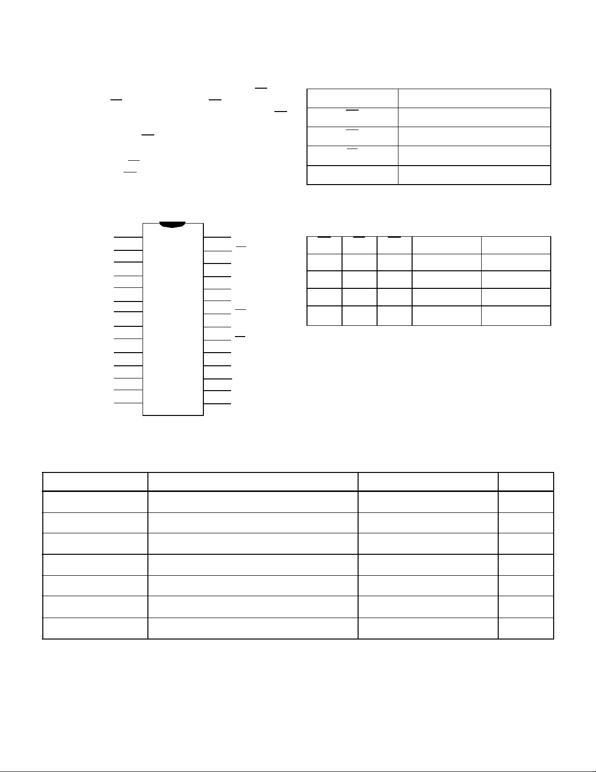
A(14:0)
CE
PE
OE
DECODER
CONTROL
LOGIC
Figure 1. PROM Block Diagram
MEMORY
ARRAY
SENSE AMPLIFIER
DQ(7:0)
PROGRAMMING
DEVICE OPERATION
PIN NAMES
The UT28F256 has three control inputs: Chip Enable (CE),
Program Enable (PE), and Output Enable (OE); fifteen address
inputs, A(14:0); and eight bidirectional data lines, DQ(7:0). CE
is the device enable input that controls chip selection, active, and
standby modes. Asserting CE causes IDD to rise to its active value
and decodes the fifteen address inputs to select one of 32,768
words in the memory. PE controls program and read operations.
During a read cycle, OE must be asserted to enable the outputs.
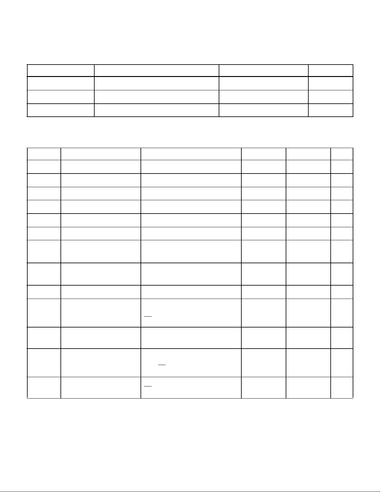
PIN CONFIGURATION
A14
A12
A7
A6
A5
A4
A3
A2
A1
A0
DQ0
DQ1
DQ2
V
SS
1
2
3
4
5
6
7
8
9
10
11
12
13
14
28
27
26
25
24
23
22
21
20
19
18
17
16
15
V
DD
PE
A13
A8
A9
A11
OE
A10
CE
DQ7
DQ6
DQ5
DQ4
DQ3
A(14:0) Address
CE Chip Enable
OE Output Enable
PE Program Enable
DQ(7:0) Data Input/Data Output
Table 1. Device Operation Truth Table
OE PE CE I/O MODE MODE
X 1 1 Three-state Standby
0 1 0 Data Out Read
1 0 0 Data In Program
1 1 0 Three-state
Notes:
1. “X” is defined as a “don’t care” condition.
2. Device active; outputs disabled.
1
Read
2
ABSOLUTE MAXIMUM RATINGS
1
(Referenced to VSS)
SYMBOL PARAMETER LIMITS UNITS
V
DD
V
I/O
T
STG
P
D
T
J
Θ
JC Thermal resistance, junction-to-case
I
I
Notes:
1. Stresses outside the listed absolute maximum ratings may cause permanent damage to the device. This is a stress rating only, and functional operation of the
device at these or any other conditions beyond limits indicated in the operational sections of this specification is not recommended. Exposure to
absolute maximum rating conditions for extended periods may affect device reliability.
2. Test per MIL-STD-883, Method 1012, infinite heat sink.
DC supply voltage -0.3 to 7.0 V
Voltage on any pin -0.5 to (V
+ 0.5) V
DD
Storage temperature -65 to +150 °C
Maximum power dissipation 1.5 W
Maximum junction temperature +175 °C
2
DC input current
3.3 °C/W
±10
mA
2
RECOMMENDED OPERATING CONDITIONS
SYMBOL PARAMETER LIMITS UNITS
V
DD
T
C
V
IN
Positive supply voltage 4.5 to 5.5 V
Case temperature range -55 to +125 °C
DC input voltage 0 to V
DD
V
DC ELECTRICAL CHARACTERISTICS (Pre/Post-Radiation)*
(V
= 5.0V ±10%; -55 °C < TC < +125 °C)
DD
SYMBOL PARAMETER CONDITION MINIMUM MAXIMUM UNIT
V
V
V
V
C
V
V
OH1
OH2
IN
IH
IL
OL1
OL2
High-level input voltage (TTL) 2.4 V
Low-level input voltage (TTL) 0.8 V
Low-level output voltage IOL = 4.0mA, V
Low-level output voltage IOL = 200µA, VDD = 4.5V (CMOS) V
= 4.5V (TTL) 0.4 V
DD
+ 0.10 V
SS
High-level output voltage IOH = -200µA, VDD = 4.5V (CMOS) VDD -0.1 V
High-level output voltage IOH = -2.0mA, VDD = 4.5V (TTL) 2.4 V
1
Input capacitance ƒ = 1MHz, VDD = 5.0V
V
= 0V
IN
15 pF
1, 4
C
IO
I
IN
I
OZ
Bidirectional I/O capacitance ƒ = 1MHz, VDD = 5.0V
V
= 0V
OUT
Input leakage current VIN = 0V to V
Three-state output leakage
current
VO = 0V to VDD
VDD = 5.5V
DD
-10 10 µA
OE = 5.5V
2,3
I
OS
I
(OP)
DD1
I
(SB)
DD2
post-rad
Notes:
* Post-radiation performance guaranteed at 25°C per MIL-STD-883 Method 1019 at 1E6 rad(Si).
1. Measured only for initial qualification, and after process or design changes that could affect input/output capacitance.
2. Supplied as a design limit but not guaranteed or tested.
3. Not more than one output may be shorted at a time for maximum duration of one second.
4. Functional test.
5. Derates at 3.0mA/MHz.
Short-circuit output current VDD = 5.5V, VO = V
VDD = 5.5V, VO = 0V
5
Supply current operating
@25.0MHz (40ns product)
@22.2MHz (45ns product)
TTL inputs levels (I
0.2V
VDD, PE = 5.5V
Supply current standby CMOS input levels VIL = VSS +0.25V
CE = V
- 0.25 V
DD
DD
= 0), V
OUT
= VDD - 0.25V
IH
IL
-90
=
15 pF
-5 5 µA
90 mA
mA
125
117
mA
mA
2 mA
3
READ CYCLE
A combination of PE greater than VIH(min), and CE less than
VIL(max) defines a read cycle. Read access time is measured
from the latter of device enable, output enable, or valid address
to valid data output.
An address access read is initiated by a change in address inputs
while the chip is enabled with OE asserted and PE deasserted.
Valid data appears on data output, DQ(7:0), after the specified
t
is satisfied. Outputs remain active throughout the entire
AVQV
cycle. As long as device enable and output enable are active, the
address inputs may change at a rate equal to the minimum read
cycle time.
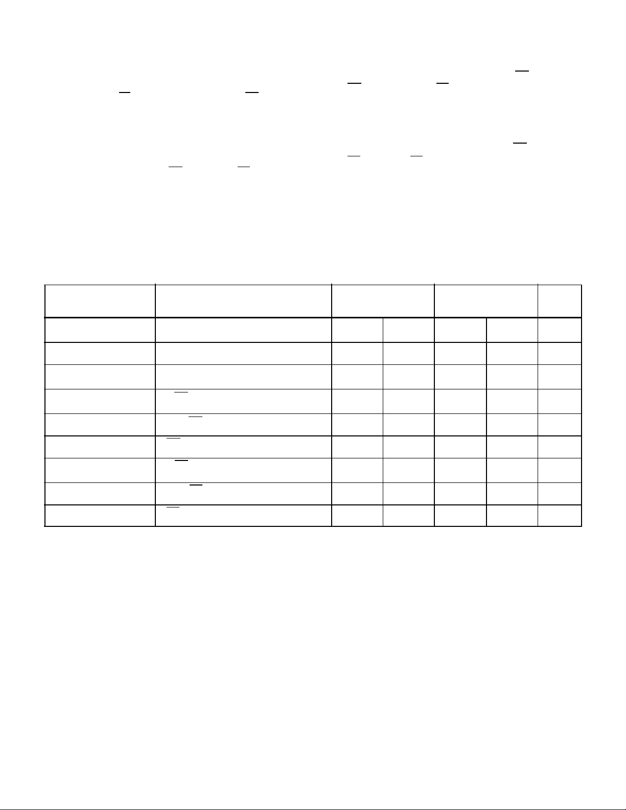
AC CHARACTERISTICS READ CYCLE (Post-Radiation)*
(V
= 5.0V ±10%; -55 °C < TC < +125 °C)
DD
SYMBOL PARAMETER 28F256-45
The chip enable-controlled access is initiated by CE going active
while OE remains asserted, PE remains deasserted, and the
addresses remain stable for the entire cycle. After the specified
t
is satisfied, the eight-bit word addressed by A(14:0)
ELQV
appears at the data outputs DQ(7:0).
Output enable-controlled access is initiated by OE going active
while CE is asserted, PE is deasserted, and the addresses are
stable. Read access time is t
GLQV
unless t
AVQV
or t
ELQV
have
not been satisfied.
MIN MAX
28F256-40
MIN MAX
UNIT
1
t
AVAV
t
AVQV
2
t
AXQX
2
t
GLQX
t
GLQV
t
GHQZ
t
ELQX2
t
ELQV
t
EHQZ
Notes:
* Post-radiation performance guaranteed at 25°C per MIL-STD-883 Method 1019 at 1E6 rads(Si).
1. Functional test.
2. Three-state is defined as a 400mV change from steady-state output voltage.
OE-controlled output enable time 0 0 ns
OE-controlled output three-state time 15 15 ns
CE-controlled output enable time 0 0 ns
CE-controlled output three-state time 15 15 ns
Read cycle time 45 40 ns
Read access time 45 40 ns
Output hold time 0 0 ns
OE-controlled access time 15 15 ns
CE-controlled access time 45 40 ns
4
 Loading...